Embed Size (px)
Citation preview
23 October 2007 07-449r0 SAS-2 Mini SAS 8i connectors and cable assemblies
1
To: T10 Technical CommitteeFrom: Rob Elliott, HP ([email protected])Date: 23 October 2007Subject: 07-449r0 SAS-2 Mini SAS 8i connectors and cable assemblies
Revision historyRevision 0 (23 October 2007) First revision
Related documentssas2r12 - Serial Attached SCSI - 2(SAS-2) revision 12SFF-8086 Specification for Mini Multilane Series: Common Elements - revision 2.2SFF-8087 Specification for Mini Multilane Series: Unshielded - revision 2.1SFF-8087 Specification for Mini Multilane Series: shielded - revision 2.8SFF-8485 Specification for Serial GPIO - revision 0.7
Overview
SFF-8086/8087/8088 define four variations of the connector: 26, 36, 50, and 68 pins.
SAS-2 currently defines signal assignments for use with these connectors:
a) 26-pin SFF-8088: Mini SAS 4xb) 36-pin SFF-8087: Mini SAS 4i (with sidebands)
This proposal adds support for:
c) 68-pin SFF-8087: Mini SAS 8i (with sidebands)
A Mini SAS 8x connector is not proposed at this time, although it would map to the 50-pin SFF-8088 connector.
Cable assemblies are proposed for:
a) Mini SAS 8i to Mini SAS 8ib) Mini SAS 8i to two Mini SAS 4i (i.e., a Y-cable)
Other variations are possible (e.g., Mini SAS 8i to four SAS Drive receptacles, or Mini SAS 8i to two SAS 4i) but not documented. Implementers of other variations should be able to figure out the signal routing based on the documented variations.
Changes to SFF-8485 are also described. There are two SGPIO busses to facilitate usage of the Y-cable.
Suggested changes to SAS-2
07-449r0 SAS-2 Mini SAS 8i connectors and cable assemblies 23 October 2007
2
5.2.3 Connectors
5.2.3.1 Connectors overview
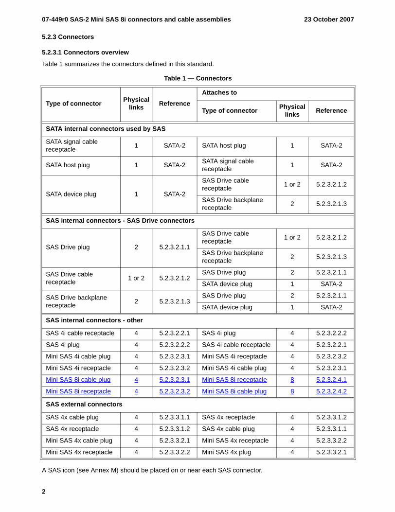
Table 1 summarizes the connectors defined in this standard.
A SAS icon (see Annex M) should be placed on or near each SAS connector.
Table 1 — Connectors
Type of connector Physical links Reference
Attaches to
Type of connector Physical links Reference
SATA internal connectors used by SAS
SATA signal cable receptacle 1 SATA-2 SATA host plug 1 SATA-2
SATA host plug 1 SATA-2 SATA signal cable receptacle 1 SATA-2
SATA device plug 1 SATA-2
SAS Drive cable receptacle 1 or 2 5.2.3.2.1.2
SAS Drive backplane receptacle 2 5.2.3.2.1.3
SAS internal connectors - SAS Drive connectors
SAS Drive plug 2 5.2.3.2.1.1
SAS Drive cable receptacle 1 or 2 5.2.3.2.1.2
SAS Drive backplane receptacle 2 5.2.3.2.1.3
SAS Drive cable receptacle 1 or 2 5.2.3.2.1.2
SAS Drive plug 2 5.2.3.2.1.1
SATA device plug 1 SATA-2
SAS Drive backplane receptacle 2 5.2.3.2.1.3
SAS Drive plug 2 5.2.3.2.1.1
SATA device plug 1 SATA-2
SAS internal connectors - other
SAS 4i cable receptacle 4 5.2.3.2.2.1 SAS 4i plug 4 5.2.3.2.2.2
SAS 4i plug 4 5.2.3.2.2.2 SAS 4i cable receptacle 4 5.2.3.2.2.1
Mini SAS 4i cable plug 4 5.2.3.2.3.1 Mini SAS 4i receptacle 4 5.2.3.2.3.2
Mini SAS 4i receptacle 4 5.2.3.2.3.2 Mini SAS 4i cable plug 4 5.2.3.2.3.1
Mini SAS 8i cable plug 4 5.2.3.2.3.1 Mini SAS 8i receptacle 8 5.2.3.2.4.1
Mini SAS 8i receptacle 4 5.2.3.2.3.2 Mini SAS 8i cable plug 8 5.2.3.2.4.2
SAS external connectors
SAS 4x cable plug 4 5.2.3.3.1.1 SAS 4x receptacle 4 5.2.3.3.1.2
SAS 4x receptacle 4 5.2.3.3.1.2 SAS 4x cable plug 4 5.2.3.3.1.1
Mini SAS 4x cable plug 4 5.2.3.3.2.1 Mini SAS 4x receptacle 4 5.2.3.3.2.2
Mini SAS 4x receptacle 4 5.2.3.3.2.2 Mini SAS 4x plug 4 5.2.3.3.2.1
23 October 2007 07-449r0 SAS-2 Mini SAS 8i connectors and cable assemblies
3
5.2.3.2 SAS internal connectors
5.2.3.2.3 Mini SAS 4i connectors
5.2.3.2.3.1 Mini SAS 4i cable plug connector
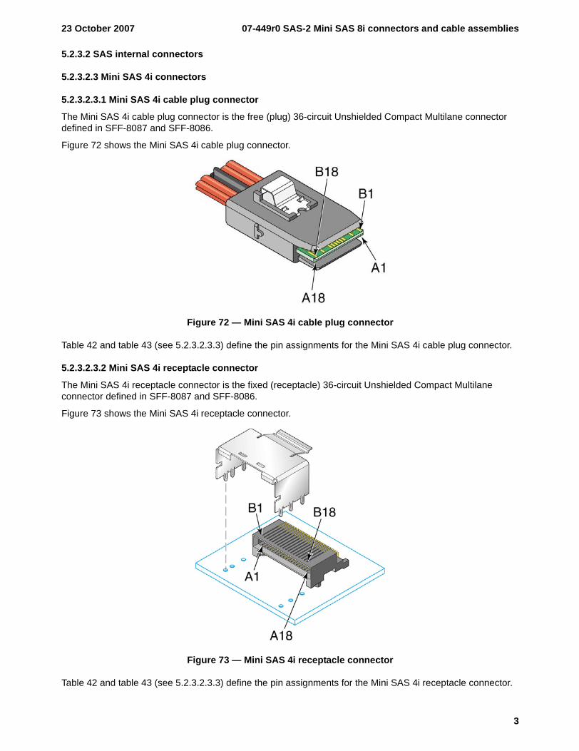
The Mini SAS 4i cable plug connector is the free (plug) 36-circuit Unshielded Compact Multilane connector defined in SFF-8087 and SFF-8086.
Figure 72 shows the Mini SAS 4i cable plug connector.
Figure 72 — Mini SAS 4i cable plug connector
Table 42 and table 43 (see 5.2.3.2.3.3) define the pin assignments for the Mini SAS 4i cable plug connector.
5.2.3.2.3.2 Mini SAS 4i receptacle connector
The Mini SAS 4i receptacle connector is the fixed (receptacle) 36-circuit Unshielded Compact Multilane connector defined in SFF-8087 and SFF-8086.
Figure 73 shows the Mini SAS 4i receptacle connector.
Figure 73 — Mini SAS 4i receptacle connector
Table 42 and table 43 (see 5.2.3.2.3.3) define the pin assignments for the Mini SAS 4i receptacle connector.
07-449r0 SAS-2 Mini SAS 8i connectors and cable assemblies 23 October 2007
4
5.2.3.2.3.3 Mini SAS 4i connector pin assignments
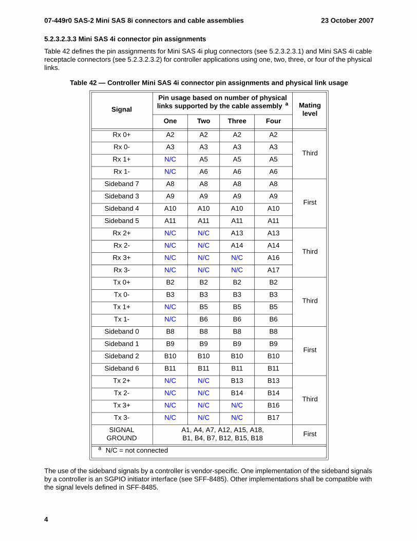
Table 42 defines the pin assignments for Mini SAS 4i plug connectors (see 5.2.3.2.3.1) and Mini SAS 4i cable receptacle connectors (see 5.2.3.2.3.2) for controller applications using one, two, three, or four of the physical links.
The use of the sideband signals by a controller is vendor-specific. One implementation of the sideband signals by a controller is an SGPIO initiator interface (see SFF-8485). Other implementations shall be compatible with the signal levels defined in SFF-8485.
Table 42 — Controller Mini SAS 4i connector pin assignments and physical link usage
SignalPin usage based on number of physical links supported by the cable assembly a Mating
levelOne Two Three Four
Rx 0+ A2 A2 A2 A2
ThirdRx 0- A3 A3 A3 A3
Rx 1+ N/C A5 A5 A5
Rx 1- N/C A6 A6 A6
Sideband 7 A8 A8 A8 A8
FirstSideband 3 A9 A9 A9 A9
Sideband 4 A10 A10 A10 A10
Sideband 5 A11 A11 A11 A11
Rx 2+ N/C N/C A13 A13
ThirdRx 2- N/C N/C A14 A14
Rx 3+ N/C N/C N/C A16
Rx 3- N/C N/C N/C A17
Tx 0+ B2 B2 B2 B2
ThirdTx 0- B3 B3 B3 B3
Tx 1+ N/C B5 B5 B5
Tx 1- N/C B6 B6 B6
Sideband 0 B8 B8 B8 B8
FirstSideband 1 B9 B9 B9 B9
Sideband 2 B10 B10 B10 B10
Sideband 6 B11 B11 B11 B11
Tx 2+ N/C N/C B13 B13
ThirdTx 2- N/C N/C B14 B14
Tx 3+ N/C N/C N/C B16
Tx 3- N/C N/C N/C B17
SIGNAL GROUND
A1, A4, A7, A12, A15, A18,B1, B4, B7, B12, B15, B18 First
a N/C = not connected
23 October 2007 07-449r0 SAS-2 Mini SAS 8i connectors and cable assemblies
5
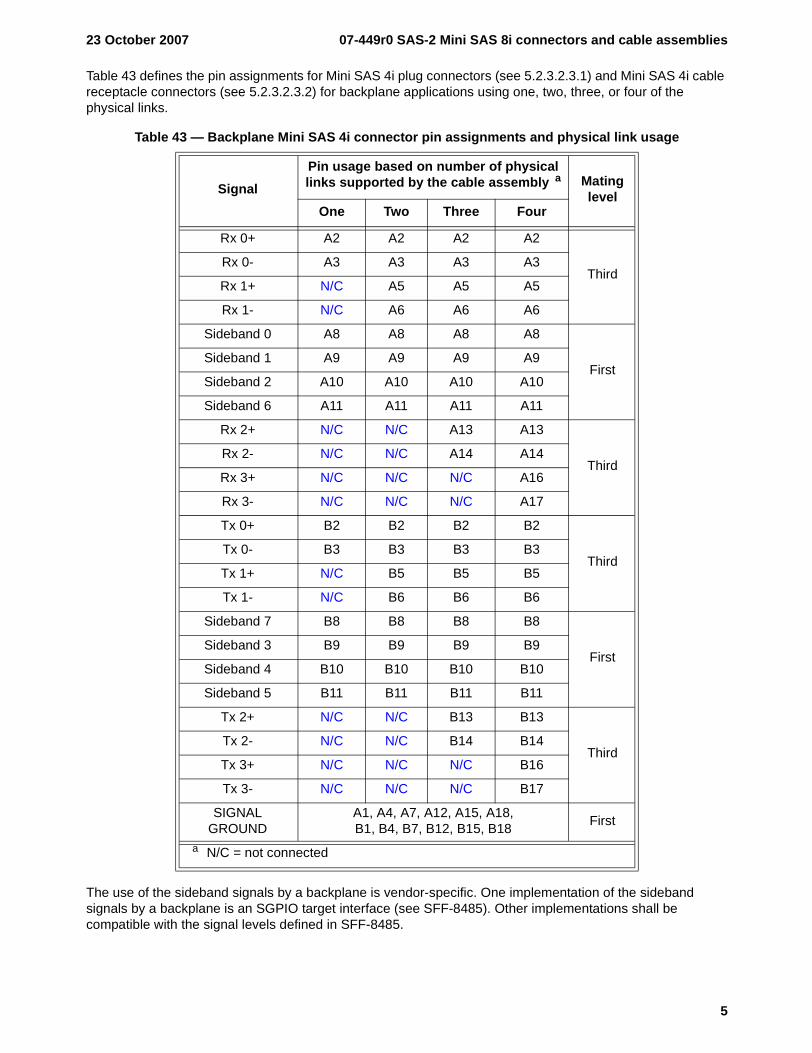
Table 43 defines the pin assignments for Mini SAS 4i plug connectors (see 5.2.3.2.3.1) and Mini SAS 4i cable receptacle connectors (see 5.2.3.2.3.2) for backplane applications using one, two, three, or four of the physical links.
The use of the sideband signals by a backplane is vendor-specific. One implementation of the sideband signals by a backplane is an SGPIO target interface (see SFF-8485). Other implementations shall be compatible with the signal levels defined in SFF-8485.
Table 43 — Backplane Mini SAS 4i connector pin assignments and physical link usage
SignalPin usage based on number of physical links supported by the cable assembly a Mating
levelOne Two Three Four
Rx 0+ A2 A2 A2 A2
ThirdRx 0- A3 A3 A3 A3
Rx 1+ N/C A5 A5 A5
Rx 1- N/C A6 A6 A6
Sideband 0 A8 A8 A8 A8
FirstSideband 1 A9 A9 A9 A9
Sideband 2 A10 A10 A10 A10
Sideband 6 A11 A11 A11 A11
Rx 2+ N/C N/C A13 A13
ThirdRx 2- N/C N/C A14 A14
Rx 3+ N/C N/C N/C A16
Rx 3- N/C N/C N/C A17
Tx 0+ B2 B2 B2 B2
ThirdTx 0- B3 B3 B3 B3
Tx 1+ N/C B5 B5 B5
Tx 1- N/C B6 B6 B6
Sideband 7 B8 B8 B8 B8
FirstSideband 3 B9 B9 B9 B9
Sideband 4 B10 B10 B10 B10
Sideband 5 B11 B11 B11 B11
Tx 2+ N/C N/C B13 B13
ThirdTx 2- N/C N/C B14 B14
Tx 3+ N/C N/C N/C B16
Tx 3- N/C N/C N/C B17
SIGNAL GROUND
A1, A4, A7, A12, A15, A18,B1, B4, B7, B12, B15, B18 First
a N/C = not connected
07-449r0 SAS-2 Mini SAS 8i connectors and cable assemblies 23 October 2007
6
5.2.3.2.4 Mini SAS 8i connectors [all new]
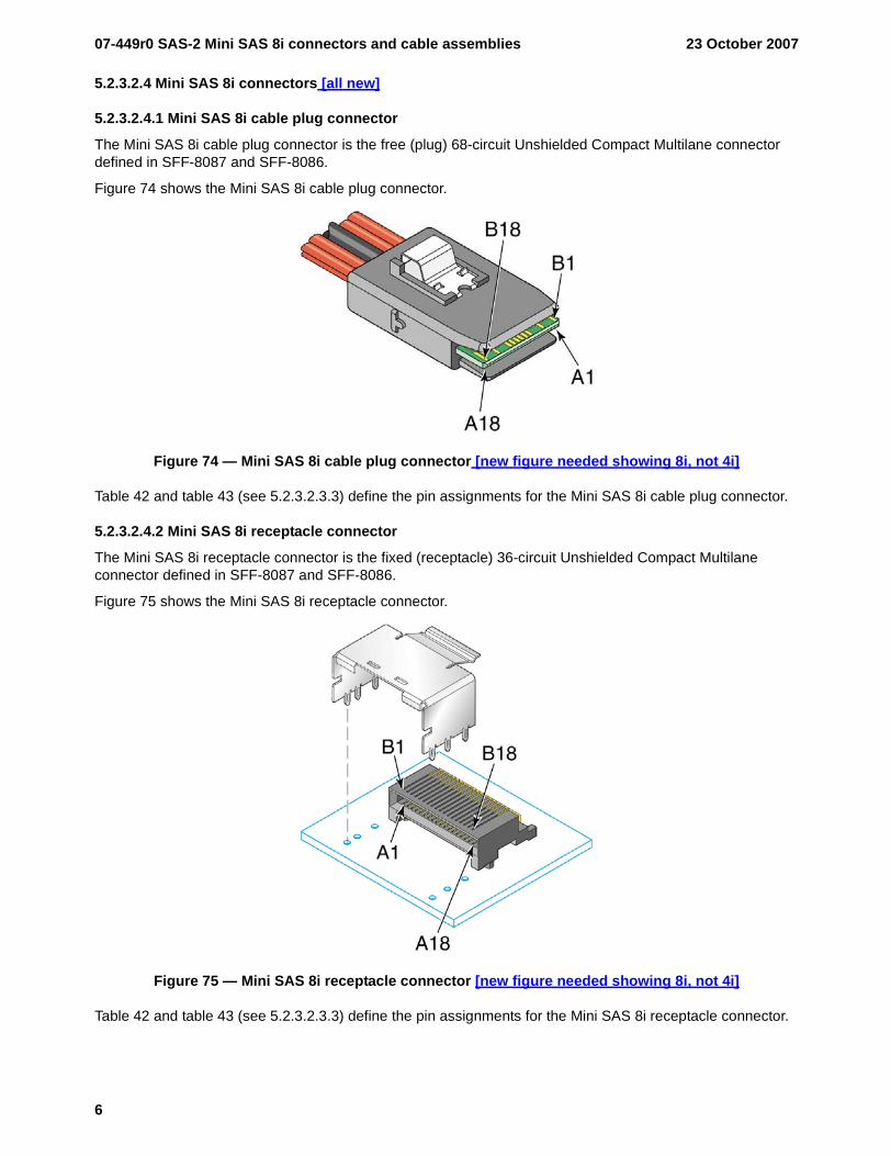
5.2.3.2.4.1 Mini SAS 8i cable plug connector
The Mini SAS 8i cable plug connector is the free (plug) 68-circuit Unshielded Compact Multilane connector defined in SFF-8087 and SFF-8086.
Figure 74 shows the Mini SAS 8i cable plug connector.
Figure 74 — Mini SAS 8i cable plug connector [new figure needed showing 8i, not 4i]
Table 42 and table 43 (see 5.2.3.2.3.3) define the pin assignments for the Mini SAS 8i cable plug connector.
5.2.3.2.4.2 Mini SAS 8i receptacle connector
The Mini SAS 8i receptacle connector is the fixed (receptacle) 36-circuit Unshielded Compact Multilane connector defined in SFF-8087 and SFF-8086.
Figure 75 shows the Mini SAS 8i receptacle connector.
Figure 75 — Mini SAS 8i receptacle connector [new figure needed showing 8i, not 4i]
Table 42 and table 43 (see 5.2.3.2.3.3) define the pin assignments for the Mini SAS 8i receptacle connector.
23 October 2007 07-449r0 SAS-2 Mini SAS 8i connectors and cable assemblies
7
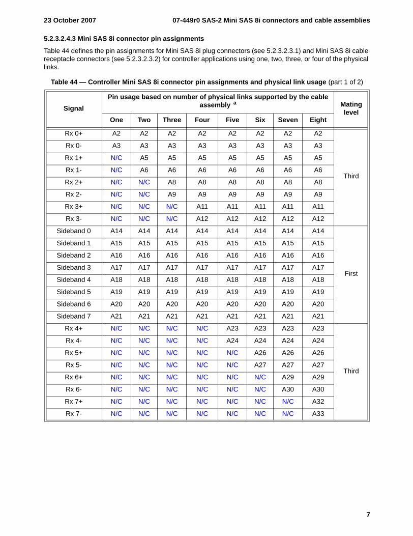
5.2.3.2.4.3 Mini SAS 8i connector pin assignments
Table 44 defines the pin assignments for Mini SAS 8i plug connectors (see 5.2.3.2.3.1) and Mini SAS 8i cable receptacle connectors (see 5.2.3.2.3.2) for controller applications using one, two, three, or four of the physical links.
Table 44 — Controller Mini SAS 8i connector pin assignments and physical link usage (part 1 of 2)
SignalPin usage based on number of physical links supported by the cable
assembly a Mating level
One Two Three Four Five Six Seven Eight
Rx 0+ A2 A2 A2 A2 A2 A2 A2 A2
Third
Rx 0- A3 A3 A3 A3 A3 A3 A3 A3
Rx 1+ N/C A5 A5 A5 A5 A5 A5 A5
Rx 1- N/C A6 A6 A6 A6 A6 A6 A6
Rx 2+ N/C N/C A8 A8 A8 A8 A8 A8
Rx 2- N/C N/C A9 A9 A9 A9 A9 A9
Rx 3+ N/C N/C N/C A11 A11 A11 A11 A11
Rx 3- N/C N/C N/C A12 A12 A12 A12 A12
Sideband 0 A14 A14 A14 A14 A14 A14 A14 A14
First
Sideband 1 A15 A15 A15 A15 A15 A15 A15 A15
Sideband 2 A16 A16 A16 A16 A16 A16 A16 A16
Sideband 3 A17 A17 A17 A17 A17 A17 A17 A17
Sideband 4 A18 A18 A18 A18 A18 A18 A18 A18
Sideband 5 A19 A19 A19 A19 A19 A19 A19 A19
Sideband 6 A20 A20 A20 A20 A20 A20 A20 A20
Sideband 7 A21 A21 A21 A21 A21 A21 A21 A21
Rx 4+ N/C N/C N/C N/C A23 A23 A23 A23
Third
Rx 4- N/C N/C N/C N/C A24 A24 A24 A24
Rx 5+ N/C N/C N/C N/C N/C A26 A26 A26
Rx 5- N/C N/C N/C N/C N/C A27 A27 A27
Rx 6+ N/C N/C N/C N/C N/C N/C A29 A29
Rx 6- N/C N/C N/C N/C N/C N/C A30 A30
Rx 7+ N/C N/C N/C N/C N/C N/C N/C A32
Rx 7- N/C N/C N/C N/C N/C N/C N/C A33
07-449r0 SAS-2 Mini SAS 8i connectors and cable assemblies 23 October 2007
8
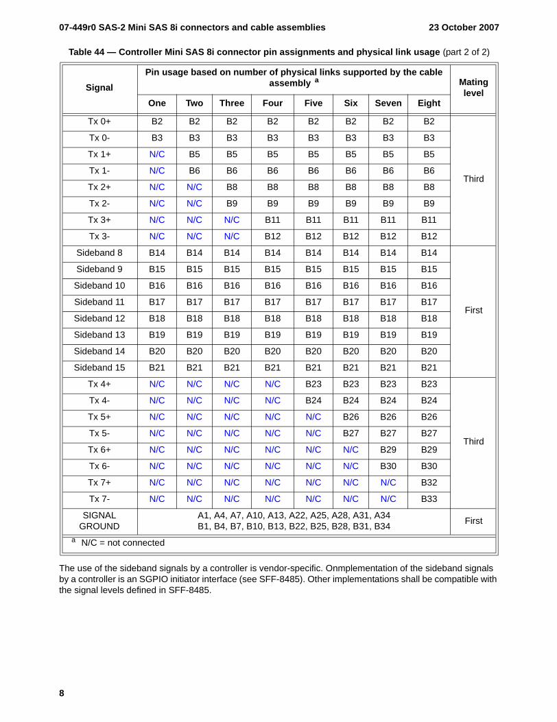
The use of the sideband signals by a controller is vendor-specific. Onmplementation of the sideband signals by a controller is an SGPIO initiator interface (see SFF-8485). Other implementations shall be compatible with the signal levels defined in SFF-8485.
Tx 0+ B2 B2 B2 B2 B2 B2 B2 B2
Third
Tx 0- B3 B3 B3 B3 B3 B3 B3 B3
Tx 1+ N/C B5 B5 B5 B5 B5 B5 B5
Tx 1- N/C B6 B6 B6 B6 B6 B6 B6
Tx 2+ N/C N/C B8 B8 B8 B8 B8 B8
Tx 2- N/C N/C B9 B9 B9 B9 B9 B9
Tx 3+ N/C N/C N/C B11 B11 B11 B11 B11
Tx 3- N/C N/C N/C B12 B12 B12 B12 B12
Sideband 8 B14 B14 B14 B14 B14 B14 B14 B14
First
Sideband 9 B15 B15 B15 B15 B15 B15 B15 B15
Sideband 10 B16 B16 B16 B16 B16 B16 B16 B16
Sideband 11 B17 B17 B17 B17 B17 B17 B17 B17
Sideband 12 B18 B18 B18 B18 B18 B18 B18 B18
Sideband 13 B19 B19 B19 B19 B19 B19 B19 B19
Sideband 14 B20 B20 B20 B20 B20 B20 B20 B20
Sideband 15 B21 B21 B21 B21 B21 B21 B21 B21
Tx 4+ N/C N/C N/C N/C B23 B23 B23 B23
Third
Tx 4- N/C N/C N/C N/C B24 B24 B24 B24
Tx 5+ N/C N/C N/C N/C N/C B26 B26 B26
Tx 5- N/C N/C N/C N/C N/C B27 B27 B27
Tx 6+ N/C N/C N/C N/C N/C N/C B29 B29
Tx 6- N/C N/C N/C N/C N/C N/C B30 B30
Tx 7+ N/C N/C N/C N/C N/C N/C N/C B32
Tx 7- N/C N/C N/C N/C N/C N/C N/C B33
SIGNAL GROUND
A1, A4, A7, A10, A13, A22, A25, A28, A31, A34B1, B4, B7, B10, B13, B22, B25, B28, B31, B34 First
a N/C = not connected
Table 44 — Controller Mini SAS 8i connector pin assignments and physical link usage (part 2 of 2)
SignalPin usage based on number of physical links supported by the cable
assembly a Mating level
One Two Three Four Five Six Seven Eight
23 October 2007 07-449r0 SAS-2 Mini SAS 8i connectors and cable assemblies
9
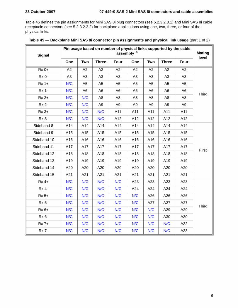
Table 45 defines the pin assignments for Mini SAS 8i plug connectors (see 5.2.3.2.3.1) and Mini SAS 8i cable receptacle connectors (see 5.2.3.2.3.2) for backplane applications using one, two, three, or four of the physical links.
Table 45 — Backplane Mini SAS 8i connector pin assignments and physical link usage (part 1 of 2)
SignalPin usage based on number of physical links supported by the cable
assembly a Mating level
One Two Three Four One Two Three Four
Rx 0+ A2 A2 A2 A2 A2 A2 A2 A2
Third
Rx 0- A3 A3 A3 A3 A3 A3 A3 A3
Rx 1+ N/C A5 A5 A5 A5 A5 A5 A5
Rx 1- N/C A6 A6 A6 A6 A6 A6 A6
Rx 2+ N/C N/C A8 A8 A8 A8 A8 A8
Rx 2- N/C N/C A9 A9 A9 A9 A9 A9
Rx 3+ N/C N/C N/C A11 A11 A11 A11 A11
Rx 3- N/C N/C N/C A12 A12 A12 A12 A12
Sideband 8 A14 A14 A14 A14 A14 A14 A14 A14
First
Sideband 9 A15 A15 A15 A15 A15 A15 A15 A15
Sideband 10 A16 A16 A16 A16 A16 A16 A16 A16
Sideband 11 A17 A17 A17 A17 A17 A17 A17 A17
Sideband 12 A18 A18 A18 A18 A18 A18 A18 A18
Sideband 13 A19 A19 A19 A19 A19 A19 A19 A19
Sideband 14 A20 A20 A20 A20 A20 A20 A20 A20
Sideband 15 A21 A21 A21 A21 A21 A21 A21 A21
Rx 4+ N/C N/C N/C N/C A23 A23 A23 A23
Third
Rx 4- N/C N/C N/C N/C A24 A24 A24 A24
Rx 5+ N/C N/C N/C N/C N/C A26 A26 A26
Rx 5- N/C N/C N/C N/C N/C A27 A27 A27
Rx 6+ N/C N/C N/C N/C N/C N/C A29 A29
Rx 6- N/C N/C N/C N/C N/C N/C A30 A30
Rx 7+ N/C N/C N/C N/C N/C N/C N/C A32
Rx 7- N/C N/C N/C N/C N/C N/C N/C A33
07-449r0 SAS-2 Mini SAS 8i connectors and cable assemblies 23 October 2007
10
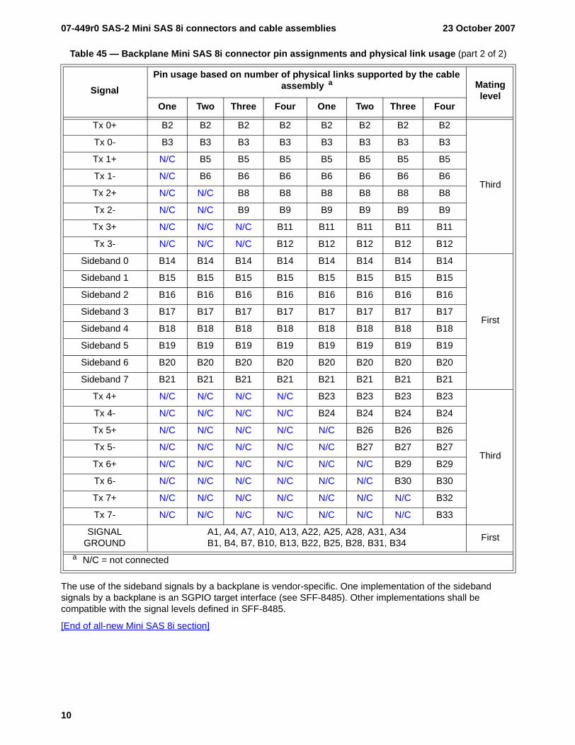
The use of the sideband signals by a backplane is vendor-specific. One implementation of the sideband signals by a backplane is an SGPIO target interface (see SFF-8485). Other implementations shall be compatible with the signal levels defined in SFF-8485.
[End of all-new Mini SAS 8i section]
Tx 0+ B2 B2 B2 B2 B2 B2 B2 B2
Third
Tx 0- B3 B3 B3 B3 B3 B3 B3 B3
Tx 1+ N/C B5 B5 B5 B5 B5 B5 B5
Tx 1- N/C B6 B6 B6 B6 B6 B6 B6
Tx 2+ N/C N/C B8 B8 B8 B8 B8 B8
Tx 2- N/C N/C B9 B9 B9 B9 B9 B9
Tx 3+ N/C N/C N/C B11 B11 B11 B11 B11
Tx 3- N/C N/C N/C B12 B12 B12 B12 B12
Sideband 0 B14 B14 B14 B14 B14 B14 B14 B14
First
Sideband 1 B15 B15 B15 B15 B15 B15 B15 B15
Sideband 2 B16 B16 B16 B16 B16 B16 B16 B16
Sideband 3 B17 B17 B17 B17 B17 B17 B17 B17
Sideband 4 B18 B18 B18 B18 B18 B18 B18 B18
Sideband 5 B19 B19 B19 B19 B19 B19 B19 B19
Sideband 6 B20 B20 B20 B20 B20 B20 B20 B20
Sideband 7 B21 B21 B21 B21 B21 B21 B21 B21
Tx 4+ N/C N/C N/C N/C B23 B23 B23 B23
Third
Tx 4- N/C N/C N/C N/C B24 B24 B24 B24
Tx 5+ N/C N/C N/C N/C N/C B26 B26 B26
Tx 5- N/C N/C N/C N/C N/C B27 B27 B27
Tx 6+ N/C N/C N/C N/C N/C N/C B29 B29
Tx 6- N/C N/C N/C N/C N/C N/C B30 B30
Tx 7+ N/C N/C N/C N/C N/C N/C N/C B32
Tx 7- N/C N/C N/C N/C N/C N/C N/C B33
SIGNAL GROUND
A1, A4, A7, A10, A13, A22, A25, A28, A31, A34B1, B4, B7, B10, B13, B22, B25, B28, B31, B34 First
a N/C = not connected
Table 45 — Backplane Mini SAS 8i connector pin assignments and physical link usage (part 2 of 2)
SignalPin usage based on number of physical links supported by the cable
assembly a Mating level
One Two Three Four One Two Three Four
23 October 2007 07-449r0 SAS-2 Mini SAS 8i connectors and cable assemblies
11
5.2.4 Cable assemblies
5.2.4.1 SAS internal cable assemblies
5.2.4.1.1 SAS internal symmetric cable assemblies
5.2.4.1.1.1 SAS internal symmetric cable assemblies overview
There are several types of SAS internal symmetric cable assemblies:
a) SAS 4i cable receptacle connectors (see 5.2.3.2.2.1) on each end (see 5.2.4.1.1.2);b) Mini SAS 4i cable plug connectors (see 5.2.3.2.3.1) on each end (see 5.2.4.1.1.3); andc) Mini SAS 8i cable plug connectors (see 5.2.3.2.4.1) on each end (see 5.2.4.1.1.4);d) a SAS 4i cable receptacle connector on one end and a Mini SAS 4i cable plug connector on the other
end, with vendor-specific sidebands (see 5.2.4.1.1.5);e) a SAS 4i cable receptacle connector on the controller end and a Mini SAS 4i cable plug connector on
the backplane end, with sidebands supporting SGPIO (see 5.2.4.1.1.6); andf) a Mini SAS 4i cable receptacle connector on the controller end and a SAS 4i cable plug connector on
the backplane end, with sidebands supporting SGPIO (see 5.2.4.1.1.7).
In a SAS internal symmetric cable assembly, the Tx signals on one end shall be connected to Rx signals on the other end (e.g., a Tx + of one connector shall connect to an Rx + of the other connector. SAS internal symmetric cable assemblies should be labeled to indicate how many physical links are included (e.g., 1X, 2X, 3X, and 4X on each connector's housing).
07-449r0 SAS-2 Mini SAS 8i connectors and cable assemblies 23 October 2007
12
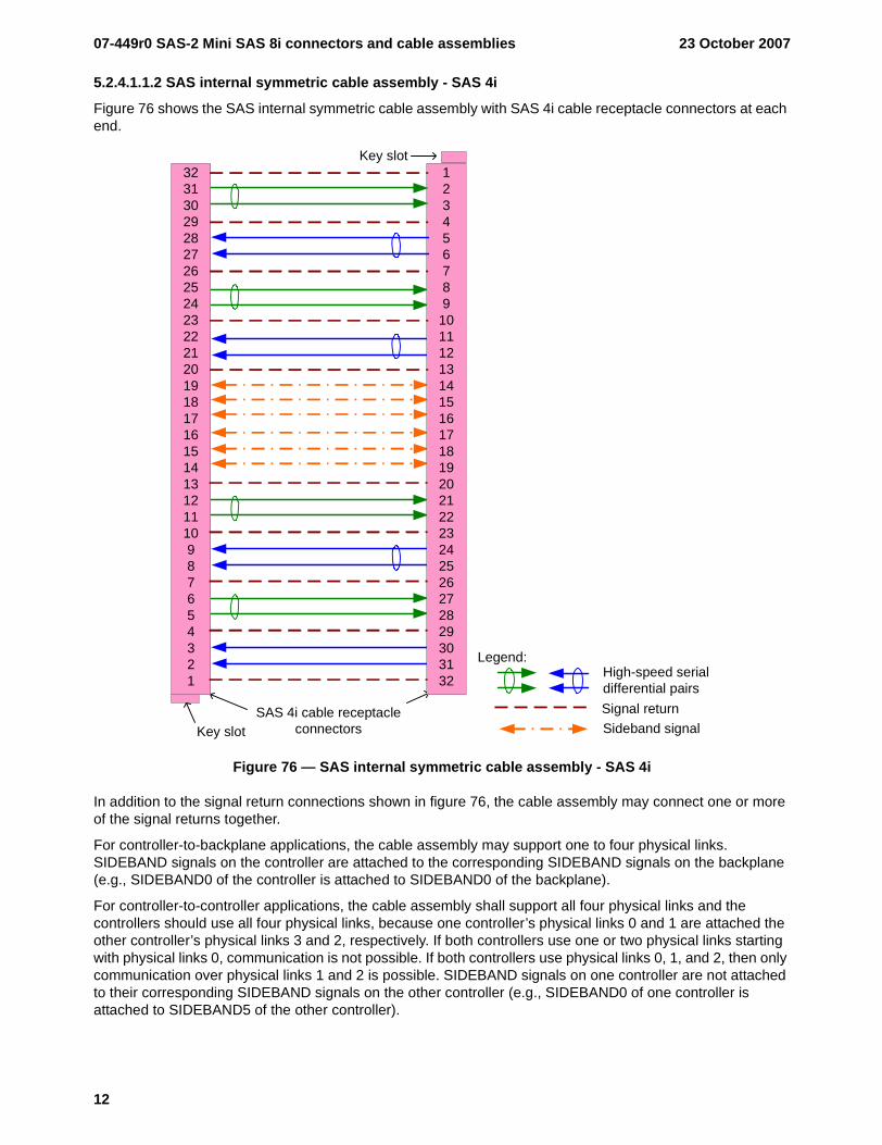
5.2.4.1.1.2 SAS internal symmetric cable assembly - SAS 4i
Figure 76 shows the SAS internal symmetric cable assembly with SAS 4i cable receptacle connectors at each end.
Figure 76 — SAS internal symmetric cable assembly - SAS 4i
In addition to the signal return connections shown in figure 76, the cable assembly may connect one or more of the signal returns together.
For controller-to-backplane applications, the cable assembly may support one to four physical links. SIDEBAND signals on the controller are attached to the corresponding SIDEBAND signals on the backplane (e.g., SIDEBAND0 of the controller is attached to SIDEBAND0 of the backplane).
For controller-to-controller applications, the cable assembly shall support all four physical links and the controllers should use all four physical links, because one controller’s physical links 0 and 1 are attached the other controller’s physical links 3 and 2, respectively. If both controllers use one or two physical links starting with physical links 0, communication is not possible. If both controllers use physical links 0, 1, and 2, then only communication over physical links 1 and 2 is possible. SIDEBAND signals on one controller are not attached to their corresponding SIDEBAND signals on the other controller (e.g., SIDEBAND0 of one controller is attached to SIDEBAND5 of the other controller).
Key slotSAS 4i cable receptacle
connectors
Key slot123456789
1011121314151617181920212223242526272829303132
3231302928272625242322212019181716151413121110987654321
Sideband signal
High-speed serial differential pairs
Legend:
Signal return
23 October 2007 07-449r0 SAS-2 Mini SAS 8i connectors and cable assemblies
13
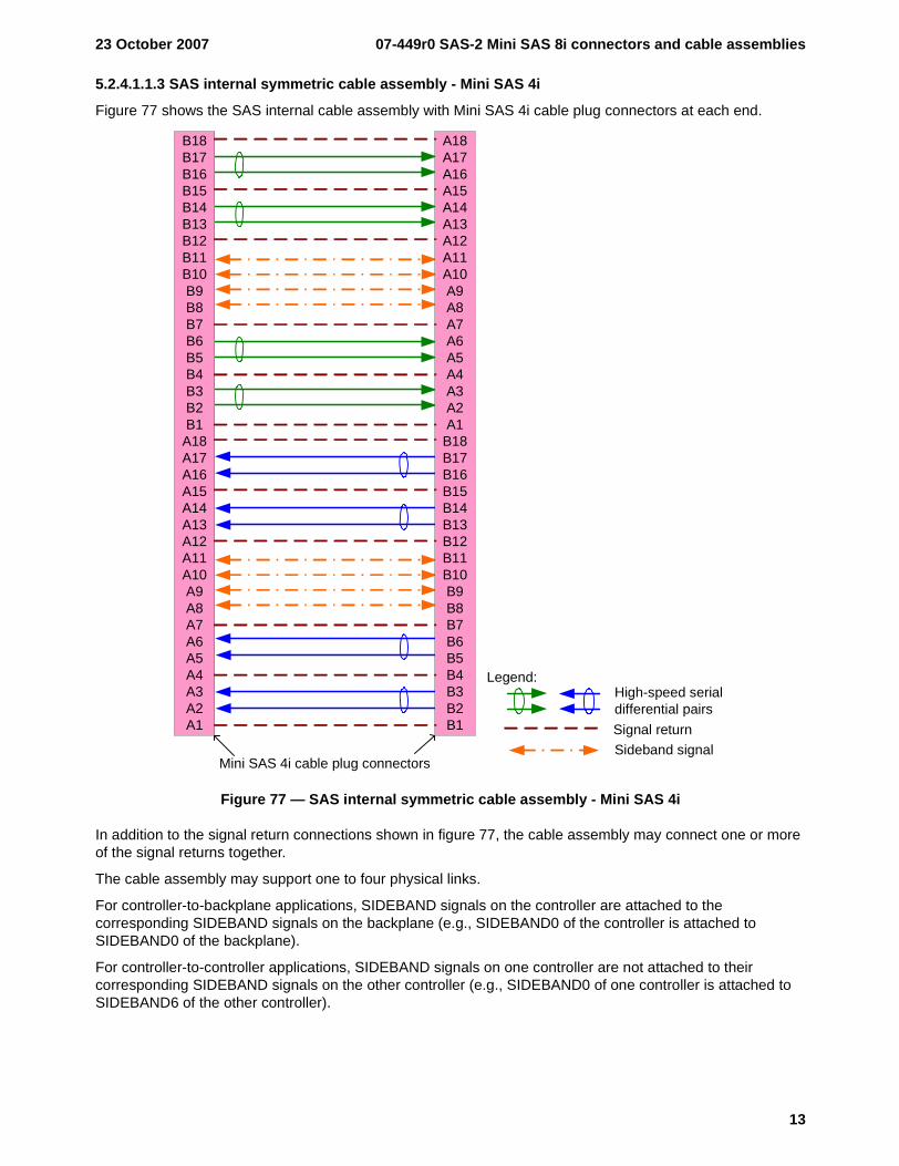
5.2.4.1.1.3 SAS internal symmetric cable assembly - Mini SAS 4i
Figure 77 shows the SAS internal cable assembly with Mini SAS 4i cable plug connectors at each end.
Figure 77 — SAS internal symmetric cable assembly - Mini SAS 4i
In addition to the signal return connections shown in figure 77, the cable assembly may connect one or more of the signal returns together.
The cable assembly may support one to four physical links.
For controller-to-backplane applications, SIDEBAND signals on the controller are attached to the corresponding SIDEBAND signals on the backplane (e.g., SIDEBAND0 of the controller is attached to SIDEBAND0 of the backplane).
For controller-to-controller applications, SIDEBAND signals on one controller are not attached to their corresponding SIDEBAND signals on the other controller (e.g., SIDEBAND0 of one controller is attached to SIDEBAND6 of the other controller).
Mini SAS 4i cable plug connectors
A18A17A16A15A14A13A12A11A10A9A8A7A6A5A4A3A2A1
B18B17B16B15B14B13B12B11B10B9B8B7B6B5B4B3B2B1
B18B17B16B15B14B13B12B11B10B9B8B7B6B5B4B3B2B1
A18A17A16A15A14A13A12A11A10A9A8A7A6A5A4A3A2A1
Sideband signal
High-speed serial differential pairs
Legend:
Signal return
07-449r0 SAS-2 Mini SAS 8i connectors and cable assemblies 23 October 2007
14
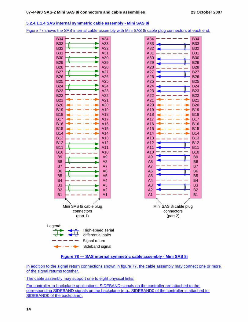
5.2.4.1.1.4 SAS internal symmetric cable assembly - Mini SAS 8i
Figure 77 shows the SAS internal cable assembly with Mini SAS 8i cable plug connectors at each end.
Figure 78 — SAS internal symmetric cable assembly - Mini SAS 8i
In addition to the signal return connections shown in figure 77, the cable assembly may connect one or more of the signal returns together.
The cable assembly may support one to eight physical links.
For controller-to-backplane applications, SIDEBAND signals on the controller are attached to the corresponding SIDEBAND signals on the backplane (e.g., SIDEBAND0 of the controller is attached to SIDEBAND0 of the backplane).
Mini SAS 8i cable plug connectors
(part 1)
A34A33A32A31A30A29A28A27A26A25A24A23A22A21A20A19A18A17A16A15A14A13A12A11A10A9A8A7A6A5A4A3A2A1
B34B33B32B31B30B29B28B27B26B25B24B23B22B21B20B19B18B17B16B15B14B13B12B11B10B9B8B7B6B5B4B3B2B1
Sideband signal
High-speed serial differential pairs
Legend:
Signal return
B34B33B32B31B30B29B28B27B26B25B24B23B22B21B20B19B18B17B16B15B14B13B12B11B10B9B8B7B6B5B4B3B2B1
A34A33A32A31A30A29A28A27A26A25A24A23A22A21A20A19A18A17A16A15A14A13A12A11A10A9A8A7A6A5A4A3A2A1
Mini SAS 8i cable plug connectors
(part 2)
23 October 2007 07-449r0 SAS-2 Mini SAS 8i connectors and cable assemblies
15
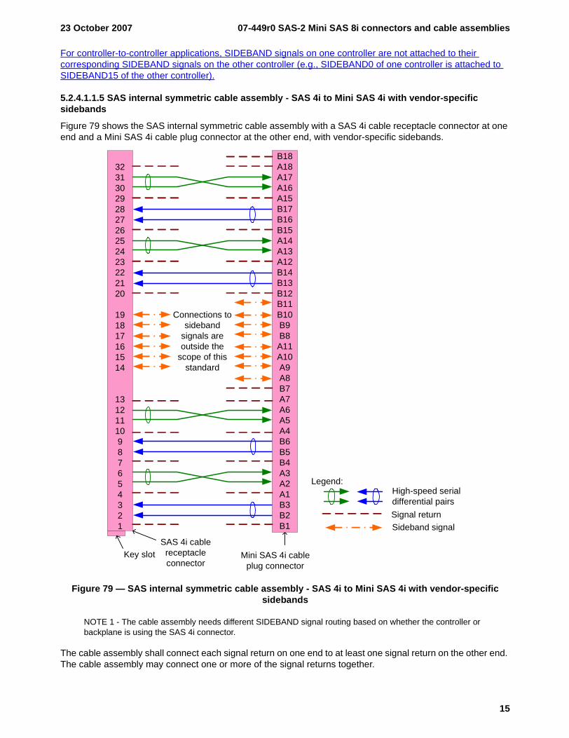
For controller-to-controller applications, SIDEBAND signals on one controller are not attached to their corresponding SIDEBAND signals on the other controller (e.g., SIDEBAND0 of one controller is attached to SIDEBAND15 of the other controller).
5.2.4.1.1.5 SAS internal symmetric cable assembly - SAS 4i to Mini SAS 4i with vendor-specific sidebands
Figure 79 shows the SAS internal symmetric cable assembly with a SAS 4i cable receptacle connector at one end and a Mini SAS 4i cable plug connector at the other end, with vendor-specific sidebands.
Figure 79 — SAS internal symmetric cable assembly - SAS 4i to Mini SAS 4i with vendor-specific sidebands
NOTE 1 - The cable assembly needs different SIDEBAND signal routing based on whether the controller or backplane is using the SAS 4i connector.
The cable assembly shall connect each signal return on one end to at least one signal return on the other end. The cable assembly may connect one or more of the signal returns together.
Key slotSAS 4i cable receptacle connector
32313029282726252423222120
191817161514
13121110987654321
Mini SAS 4i cable plug connector
B18A18A17A16A15B17B16B15A14A13A12B14B13B12B11B10B9B8A11A10A9A8B7A7A6A5A4B6B5B4A3A2A1B3B2B1 Sideband signal
High-speed serial differential pairs
Legend:
Signal return
Connections to sideband
signals are outside the
scope of this standard

07-449r0 SAS-2 Mini SAS 8i connectors and cable assemblies 23 October 2007
16
For controller-to-backplane applications with the SAS 4i cable receptacle connector on the controller end, the cable assembly may support one to four physical links.
For controller-to-controller applications, the cable assembly may support one to four physical links.
For controller-to-backplane applications with the Mini SAS 4i cable receptacle connector on the controller end, the cable assembly shall support all four physical links and the controller should use all four physical links, because the controller’s physical links 0, 1, 2, and 3 are attached to the backplane’s physical links 3, 2, 1, and 0, respectively. If both controllers use one or two physical links starting with physical links 0, communication is not possible. If both controllers use physical links 0, 1, and 2, then only communication over physical links 1 and 2 is possible.
23 October 2007 07-449r0 SAS-2 Mini SAS 8i connectors and cable assemblies
17
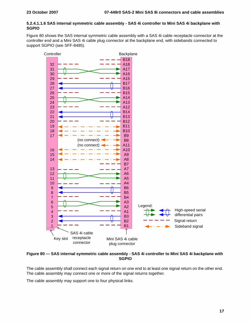
5.2.4.1.1.6 SAS internal symmetric cable assembly - SAS 4i controller to Mini SAS 4i backplane with SGPIO
Figure 80 shows the SAS internal symmetric cable assembly with a SAS 4i cable receptacle connector at the controller end and a Mini SAS 4i cable plug connector at the backplane end, with sidebands connected to support SGPIO (see SFF-8485).
Figure 80 — SAS internal symmetric cable assembly - SAS 4i controller to Mini SAS 4i backplane with SGPIO
The cable assembly shall connect each signal return on one end to at least one signal return on the other end. The cable assembly may connect one or more of the signal returns together.
The cable assembly may support one to four physical links.
Controller Backplane
Key slotSAS 4i cable
receptacle connector
32313029282726252423222120191817
161514
13121110987654321
Mini SAS 4i cable plug connector
B18A18A17A16A15B17B16B15A14A13A12B14B13B12B11B10B9B8
A11A10A9A8B7A7A6A5A4B6B5B4A3A2A1B3B2B1 Sideband signal
High-speed serial differential pairs
Legend:
Signal return
(no connect)(no connect)
07-449r0 SAS-2 Mini SAS 8i connectors and cable assemblies 23 October 2007
18
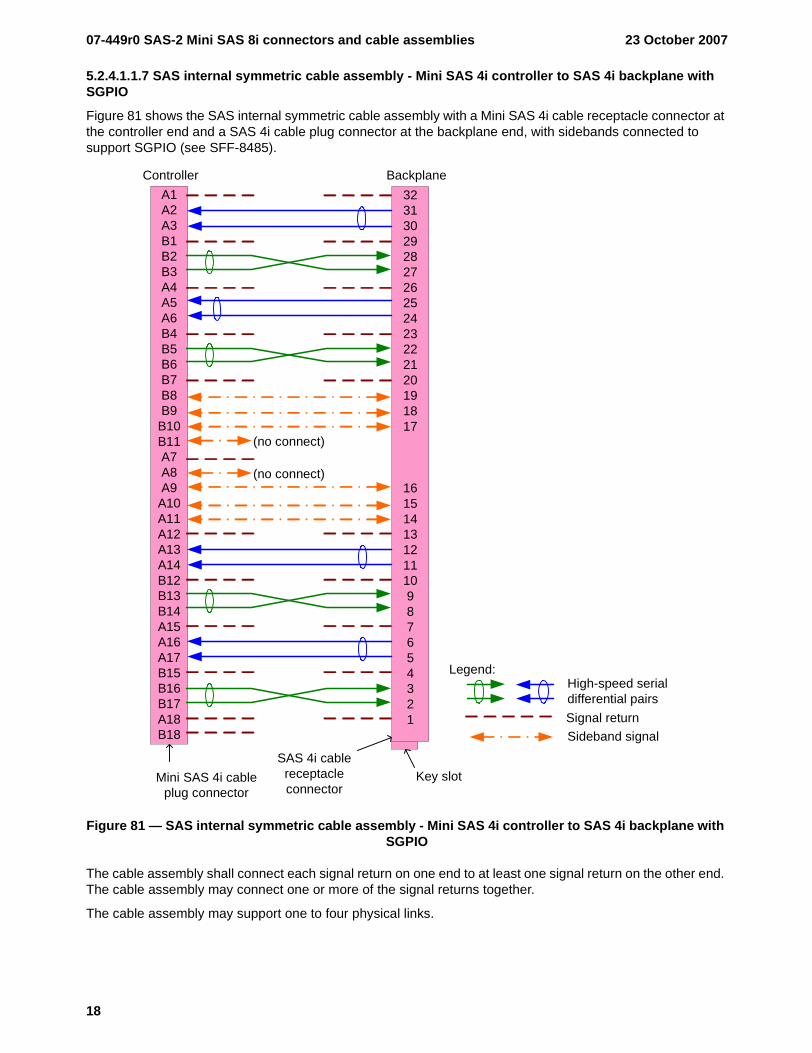
5.2.4.1.1.7 SAS internal symmetric cable assembly - Mini SAS 4i controller to SAS 4i backplane with SGPIO
Figure 81 shows the SAS internal symmetric cable assembly with a Mini SAS 4i cable receptacle connector at the controller end and a SAS 4i cable plug connector at the backplane end, with sidebands connected to support SGPIO (see SFF-8485).
Figure 81 — SAS internal symmetric cable assembly - Mini SAS 4i controller to SAS 4i backplane with SGPIO
The cable assembly shall connect each signal return on one end to at least one signal return on the other end. The cable assembly may connect one or more of the signal returns together.
The cable assembly may support one to four physical links.
Key slotSAS 4i cable
receptacle connector
32313029282726252423222120191817
16151413121110987654321
Mini SAS 4i cable plug connector
A1A2A3B1B2B3A4A5A6B4B5B6B7B8B9B10B11A7A8A9A10A11A12A13A14B12B13B14A15A16A17B15B16B17A18B18 Sideband signal
High-speed serial differential pairs
Legend:
Signal return
(no connect)
(no connect)
Controller Backplane
23 October 2007 07-449r0 SAS-2 Mini SAS 8i connectors and cable assemblies
19
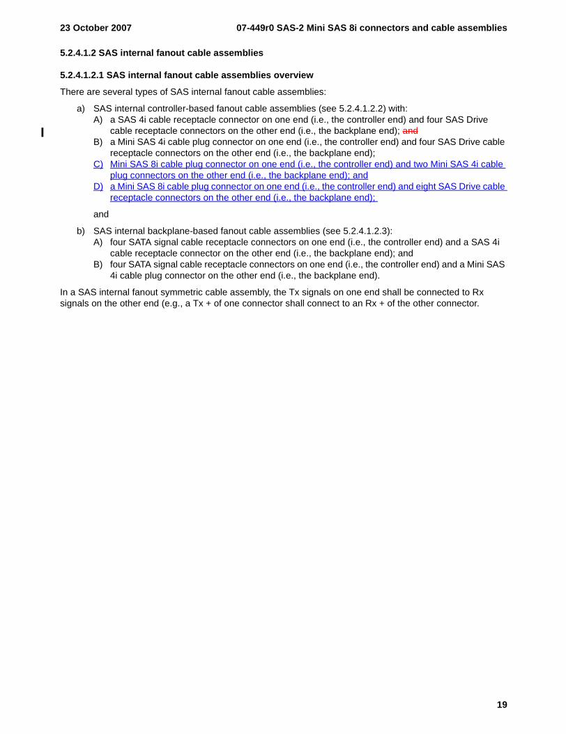
5.2.4.1.2 SAS internal fanout cable assemblies
5.2.4.1.2.1 SAS internal fanout cable assemblies overview
There are several types of SAS internal fanout cable assemblies:
a) SAS internal controller-based fanout cable assemblies (see 5.2.4.1.2.2) with:A) a SAS 4i cable receptacle connector on one end (i.e., the controller end) and four SAS Drive
cable receptacle connectors on the other end (i.e., the backplane end); andB) a Mini SAS 4i cable plug connector on one end (i.e., the controller end) and four SAS Drive cable
receptacle connectors on the other end (i.e., the backplane end);C) Mini SAS 8i cable plug connector on one end (i.e., the controller end) and two Mini SAS 4i cable
plug connectors on the other end (i.e., the backplane end); andD) a Mini SAS 8i cable plug connector on one end (i.e., the controller end) and eight SAS Drive cable
receptacle connectors on the other end (i.e., the backplane end);
and
b) SAS internal backplane-based fanout cable assemblies (see 5.2.4.1.2.3):A) four SATA signal cable receptacle connectors on one end (i.e., the controller end) and a SAS 4i
cable receptacle connector on the other end (i.e., the backplane end); andB) four SATA signal cable receptacle connectors on one end (i.e., the controller end) and a Mini SAS
4i cable plug connector on the other end (i.e., the backplane end).
In a SAS internal fanout symmetric cable assembly, the Tx signals on one end shall be connected to Rx signals on the other end (e.g., a Tx + of one connector shall connect to an Rx + of the other connector.
07-449r0 SAS-2 Mini SAS 8i connectors and cable assemblies 23 October 2007
20
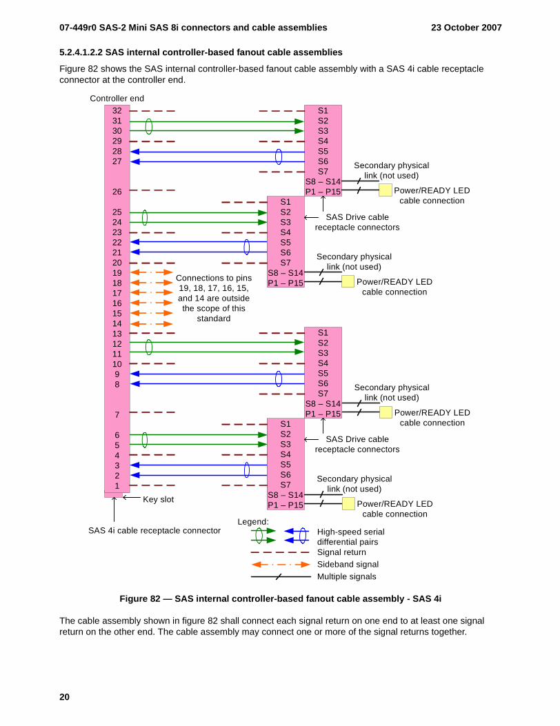
5.2.4.1.2.2 SAS internal controller-based fanout cable assemblies
Figure 82 shows the SAS internal controller-based fanout cable assembly with a SAS 4i cable receptacle connector at the controller end.
Figure 82 — SAS internal controller-based fanout cable assembly - SAS 4i
The cable assembly shown in figure 82 shall connect each signal return on one end to at least one signal return on the other end. The cable assembly may connect one or more of the signal returns together.
Key slot
SAS 4i cable receptacle connector
S1S2S3S4S5S6S7
S8 – S14P1 – P15
323130292827
26
2524232221201918171615141312111098
7
654321
Controller end
S1S2S3S4S5S6S7
S8 – S14P1 – P15
S1S2S3S4S5S6S7
S8 – S14P1 – P15
S1S2S3S4S5S6S7
S8 – S14P1 – P15
SAS Drive cable receptacle connectors
SAS Drive cable receptacle connectors
Power/READY LED cable connection
Secondary physical link (not used)
Power/READY LED cable connection
Secondary physical link (not used)
Power/READY LED cable connection
Secondary physical link (not used)
Power/READY LED cable connection
Secondary physical link (not used)
High-speed serial differential pairsSignal returnSideband signal
Legend:
Multiple signals
Connections to pins 19, 18, 17, 16, 15, and 14 are outside the scope of this
standard
23 October 2007 07-449r0 SAS-2 Mini SAS 8i connectors and cable assemblies
21
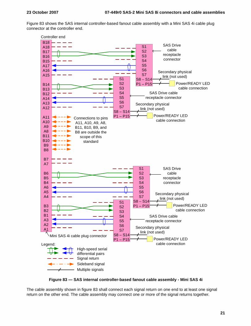
Figure 83 shows the SAS internal controller-based fanout cable assembly with a Mini SAS 4i cable plug connector at the controller end.
Figure 83 — SAS internal controller-based fanout cable assembly - Mini SAS 4i
The cable assembly shown in figure 83 shall connect each signal return on one end to at least one signal return on the other end. The cable assembly may connect one or more of the signal returns together.
Mini SAS 4i cable plug connector
S1S2S3S4S5S6S7
S8 – S14P1 – P15
B18A18B17B16B15A17A16A15
B14B13B12A14A13A12
A11A10A9A8
B11B10B9B8
B7A7
B6B5B4A6A5A4
B3B2B1A3A2A1
Controller end
S1S2S3S4S5S6S7
S8 – S14P1 – P15
S1S2S3S4S5S6S7
S8 – S14P1 – P15
S1S2S3S4S5S6S7
S8 – S14P1 – P15
Power/READY LED cable connection
Secondary physical link (not used)
Power/READY LED cable connection
Secondary physical link (not used)
Power/READY LED cable connection
Secondary physical link (not used)
Power/READY LED cable connection
Secondary physical link (not used)
SAS Drive cable
receptacle connector
SAS Drive cable receptacle connector
SAS Drive cable receptacle connector
SAS Drive cable
receptacle connector
High-speed serial differential pairsSignal returnSideband signal
Legend:
Multiple signals
Connections to pins A11, A10, A9, A8, B11, B10, B9, and B8 are outside the
scope of this standard
07-449r0 SAS-2 Mini SAS 8i connectors and cable assemblies 23 October 2007
22
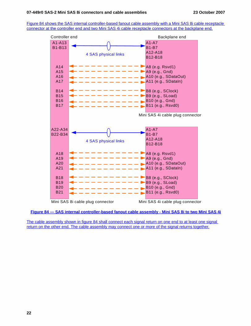
Figure 84 shows the SAS internal controller-based fanout cable assembly with a Mini SAS 8i cable receptacle connector at the controller end and two Mini SAS 4i cable receptacle connectors at the backplane end.
Figure 84 — SAS internal controller-based fanout cable assembly - Mini SAS 8i to two Mini SAS 4i
The cable assembly shown in figure 84 shall connect each signal return on one end to at least one signal return on the other end. The cable assembly may connect one or more of the signal returns together.
Mini SAS 8i cable plug connector
A1-A13B1-B13
A14A15A16A17
B14B15B16B17
A22-A34B22-B34
A18A19A20A21
B18B19B20B21
Controller endA1-A7B1-B7A12-A18B12-B18
A8 (e.g. Rsvd1)A9 (e.g., Gnd)A10 (e.g., SDataOut)A11 (e.g., SDataIn)
B8 (e.g., SClock)B9 (e.g., SLoad)B10 (e.g., Gnd)B11 (e.g., Rsvd0)
Backplane end
A1-A7B1-B7A12-A18B12-B18
A8 (e.g. Rsvd1)A9 (e.g., Gnd)A10 (e.g., SDataOut)A11 (e.g., SDataIn)
B8 (e.g., SClock)B9 (e.g., SLoad)B10 (e.g., Gnd)B11 (e.g., Rsvd0)
4 SAS physical links
4 SAS physical links
Mini SAS 4i cable plug connector
Mini SAS 4i cable plug connector
23 October 2007 07-449r0 SAS-2 Mini SAS 8i connectors and cable assemblies
23
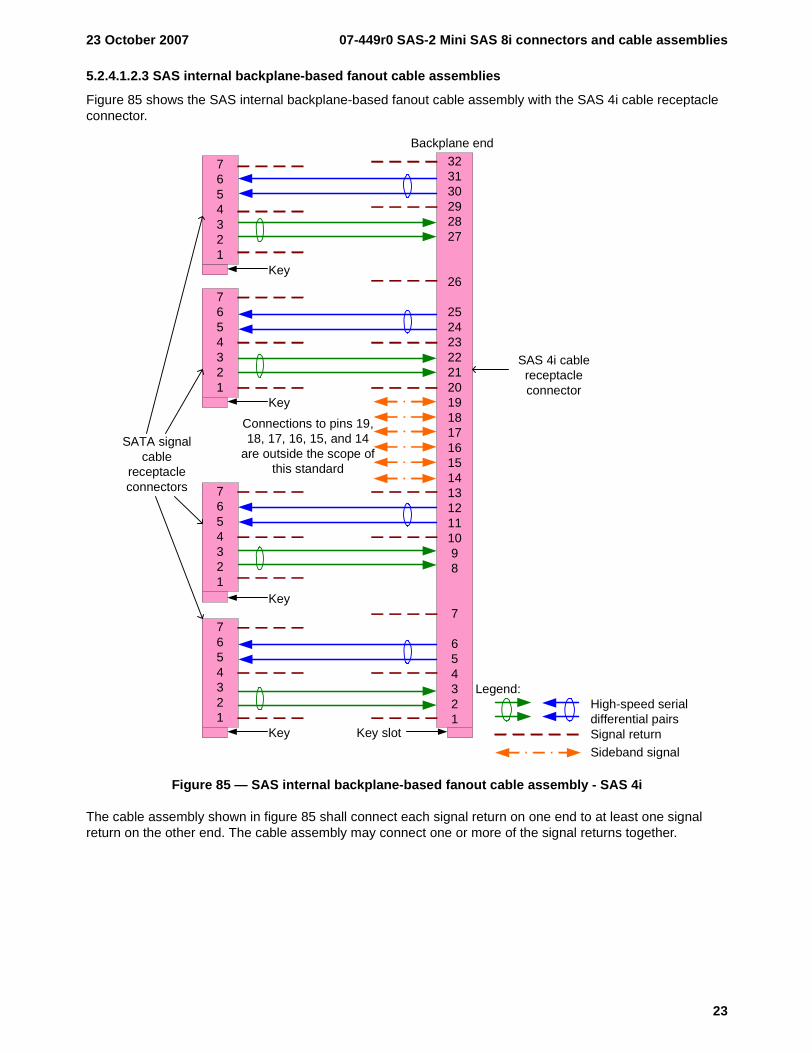
5.2.4.1.2.3 SAS internal backplane-based fanout cable assemblies
Figure 85 shows the SAS internal backplane-based fanout cable assembly with the SAS 4i cable receptacle connector.
Figure 85 — SAS internal backplane-based fanout cable assembly - SAS 4i
The cable assembly shown in figure 85 shall connect each signal return on one end to at least one signal return on the other end. The cable assembly may connect one or more of the signal returns together.
SAS 4i cable receptacle connector
7654321
323130292827
26
2524232221201918171615141312111098
7
654321
Backplane end
SATA signal cable
receptacle connectors 7
654321
7654321
7654321
Key
Key
Key
Key Key slot
High-speed serial differential pairsSignal returnSideband signal
Legend:
Connections to pins 19, 18, 17, 16, 15, and 14
are outside the scope of this standard
07-449r0 SAS-2 Mini SAS 8i connectors and cable assemblies 23 October 2007
24
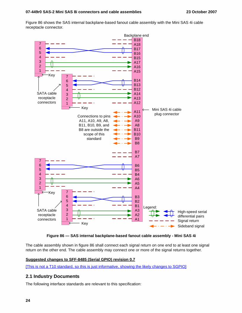
Figure 86 shows the SAS internal backplane-based fanout cable assembly with the Mini SAS 4i cable receptacle connector.
Figure 86 — SAS internal backplane-based fanout cable assembly - Mini SAS 4i
The cable assembly shown in figure 86 shall connect each signal return on one end to at least one signal return on the other end. The cable assembly may connect one or more of the signal returns together.
Suggested changes to SFF-8485 (Serial GPIO) revision 0.7
[This is not a T10 standard, so this is just informative, showing the likely changes to SGPIO]
2.1 Industry DocumentsThe following interface standards are relevant to this specification:
7654321
Backplane end
7654321
7654321
7654321
Key
Key
Key
Key
B18A18B17B16B15A17A16A15
B14B13B12A14A13A12
A11A10A9A8
B11B10B9B8
B7A7
B6B5B4A6A5A4
B3B2B1A3A2A1
Mini SAS 4i cable plug connector
SATA cable receptacle connectors
SATA cable receptacle connectors
High-speed serial differential pairsSignal returnSideband signal
Legend:
Connections to pins A11, A10, A9, A8, B11, B10, B9, and B8 are outside the
scope of this standard
23 October 2007 07-449r0 SAS-2 Mini SAS 8i connectors and cable assemblies
25
EIA/JEDEC JESD8-B Interface Standard for Nominal 3 V/3.3 V Supply Digital Integrated Circuits (LVTTL). See http://www.jedec.org.
ISO/IEC 14776-150 Serial Attached SCSI (SAS) standard (ANSI INCITS 376-2003). See http://www.iso.int, http://www.ansi.org, or http://www.incits.org (developed by T10 at http://www.t10.org).
ISO/IEC 14776-151 Serial Attached SCSI 1.1 (SAS-1.1) standard (ANSI INCITS 417-2006). See http://www.iso.int, http://www.ansi.org, or http://www.incits.org (developed by T10 at http://www.t10.org).
ISO/IEC 14776-152 Serial Attached SCSI 2 (SAS-2) standard. Under development. See http://www.iso.int, http://www.ansi.org, or http://www.incits.org (developed by T10 at http://www.t10.org).
PCI Express ExpressModule Electromechanical Specification (PCI-EM) Revision 1.0. See http://www.pcisig.com.
Serial ATA (SATA) Revision 2.5. See http://www.sata-io.org.
9.1 Applications overviewSGPIO may be used in several applications:
a) Serial Attached SCSI SAS 4i, or Mini SAS 4i connector, or Mini SAS 8i connector (see SAS-1.1SAS-2, SFF-8484, SFF-8086, and SFF-8087);
b) Serial Attached SCSI backplanes (see SAS-1.1SAS-2);c) Serial ATA internal 4 Lane connector (see SATA); andd) PCI Express Server IO Module (see SIOM).
NOTE 2 - SGPIO may or may not have been endorsed for such usage by the corresponding standards bodies/consortiums.
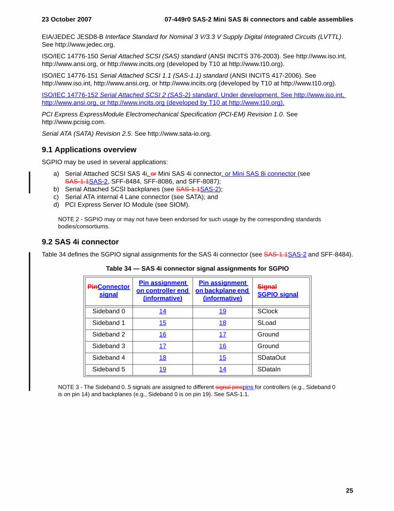
9.2 SAS 4i connectorTable 34 defines the SGPIO signal assignments for the SAS 4i connector (see SAS-1.1SAS-2 and SFF-8484).
NOTE 3 - The Sideband 0..5 signals are assigned to different signal pinspins for controllers (e.g., Sideband 0 is on pin 14) and backplanes (e.g., Sideband 0 is on pin 19). See SAS-1.1.
Table 34 — SAS 4i connector signal assignments for SGPIO
PinConnector signal
Pin assignment on controller end
(informative)
Pin assignment on backplane end
(informative)
SignalSGPIO signal
Sideband 0 14 19 SClock
Sideband 1 15 18 SLoad
Sideband 2 16 17 Ground
Sideband 3 17 16 Ground
Sideband 4 18 15 SDataOut
Sideband 5 19 14 SDataIn
07-449r0 SAS-2 Mini SAS 8i connectors and cable assemblies 23 October 2007
26
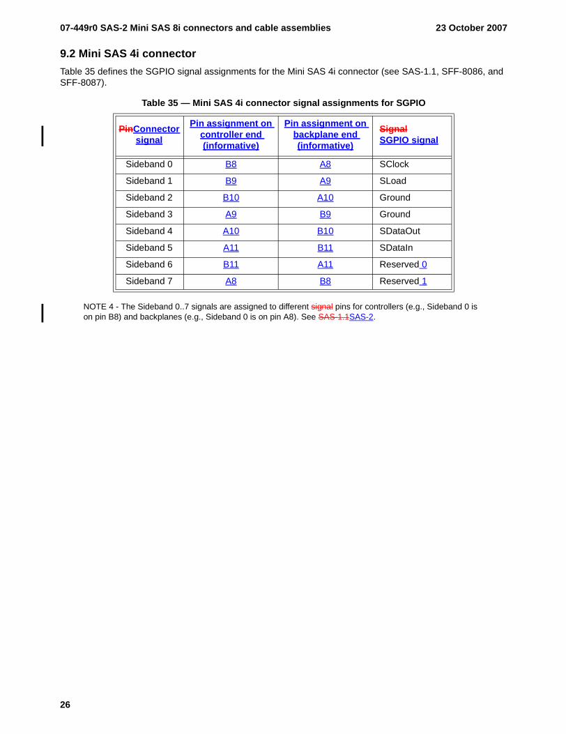
9.2 Mini SAS 4i connectorTable 35 defines the SGPIO signal assignments for the Mini SAS 4i connector (see SAS-1.1, SFF-8086, and SFF-8087).
NOTE 4 - The Sideband 0..7 signals are assigned to different signal pins for controllers (e.g., Sideband 0 is on pin B8) and backplanes (e.g., Sideband 0 is on pin A8). See SAS-1.1SAS-2.
Table 35 — Mini SAS 4i connector signal assignments for SGPIO
PinConnector signal
Pin assignment on controller end (informative)
Pin assignment on backplane end (informative)
SignalSGPIO signal
Sideband 0 B8 A8 SClock
Sideband 1 B9 A9 SLoad
Sideband 2 B10 A10 Ground
Sideband 3 A9 B9 Ground
Sideband 4 A10 B10 SDataOut
Sideband 5 A11 B11 SDataIn
Sideband 6 B11 A11 Reserved 0
Sideband 7 A8 B8 Reserved 1
23 October 2007 07-449r0 SAS-2 Mini SAS 8i connectors and cable assemblies
27
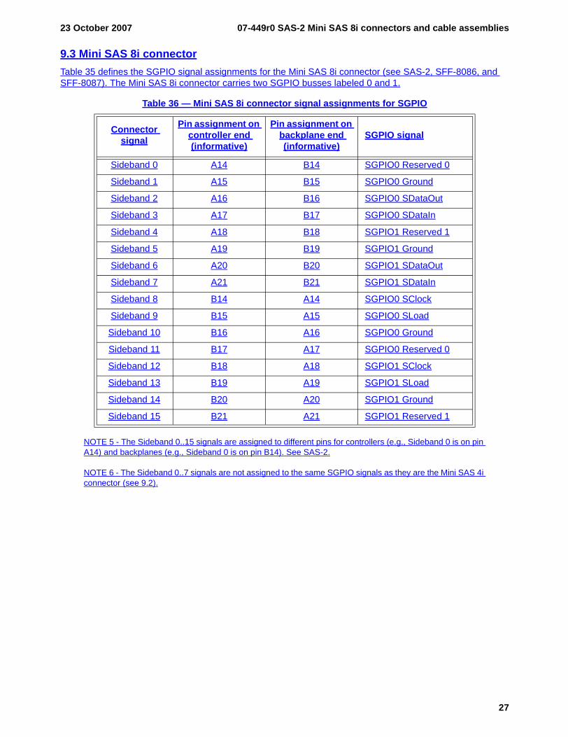
9.3 Mini SAS 8i connectorTable 35 defines the SGPIO signal assignments for the Mini SAS 8i connector (see SAS-2, SFF-8086, and SFF-8087). The Mini SAS 8i connector carries two SGPIO busses labeled 0 and 1.
NOTE 5 - The Sideband 0..15 signals are assigned to different pins for controllers (e.g., Sideband 0 is on pin A14) and backplanes (e.g., Sideband 0 is on pin B14). See SAS-2.
NOTE 6 - The Sideband 0..7 signals are not assigned to the same SGPIO signals as they are the Mini SAS 4i connector (see 9.2).
Table 36 — Mini SAS 8i connector signal assignments for SGPIO
Connector signal
Pin assignment on controller end (informative)
Pin assignment on backplane end (informative)
SGPIO signal
Sideband 0 A14 B14 SGPIO0 Reserved 0
Sideband 1 A15 B15 SGPIO0 Ground
Sideband 2 A16 B16 SGPIO0 SDataOut
Sideband 3 A17 B17 SGPIO0 SDataIn
Sideband 4 A18 B18 SGPIO1 Reserved 1
Sideband 5 A19 B19 SGPIO1 Ground
Sideband 6 A20 B20 SGPIO1 SDataOut
Sideband 7 A21 B21 SGPIO1 SDataIn
Sideband 8 B14 A14 SGPIO0 SClock
Sideband 9 B15 A15 SGPIO0 SLoad
Sideband 10 B16 A16 SGPIO0 Ground
Sideband 11 B17 A17 SGPIO0 Reserved 0
Sideband 12 B18 A18 SGPIO1 SClock
Sideband 13 B19 A19 SGPIO1 SLoad
Sideband 14 B20 A20 SGPIO1 Ground
Sideband 15 B21 A21 SGPIO1 Reserved 1
07-449r0 SAS-2 Mini SAS 8i connectors and cable assemblies 23 October 2007
28
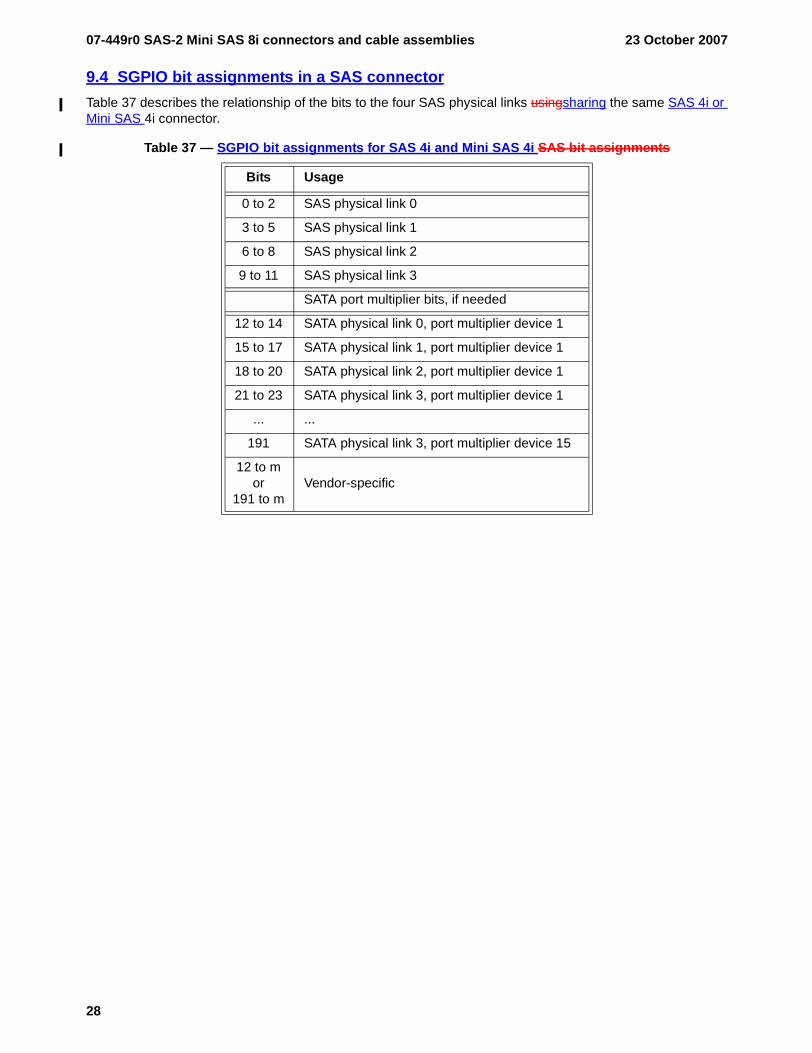
9.4 SGPIO bit assignments in a SAS connectorTable 37 describes the relationship of the bits to the four SAS physical links usingsharing the same SAS 4i or Mini SAS 4i connector.
Table 37 — SGPIO bit assignments for SAS 4i and Mini SAS 4i SAS bit assignments
Bits Usage
0 to 2 SAS physical link 0
3 to 5 SAS physical link 1
6 to 8 SAS physical link 2
9 to 11 SAS physical link 3
SATA port multiplier bits, if needed
12 to 14 SATA physical link 0, port multiplier device 1
15 to 17 SATA physical link 1, port multiplier device 1
18 to 20 SATA physical link 2, port multiplier device 1
21 to 23 SATA physical link 3, port multiplier device 1
... ...
191 SATA physical link 3, port multiplier device 15
12 to mor
191 to mVendor-specific
23 October 2007 07-449r0 SAS-2 Mini SAS 8i connectors and cable assemblies
29
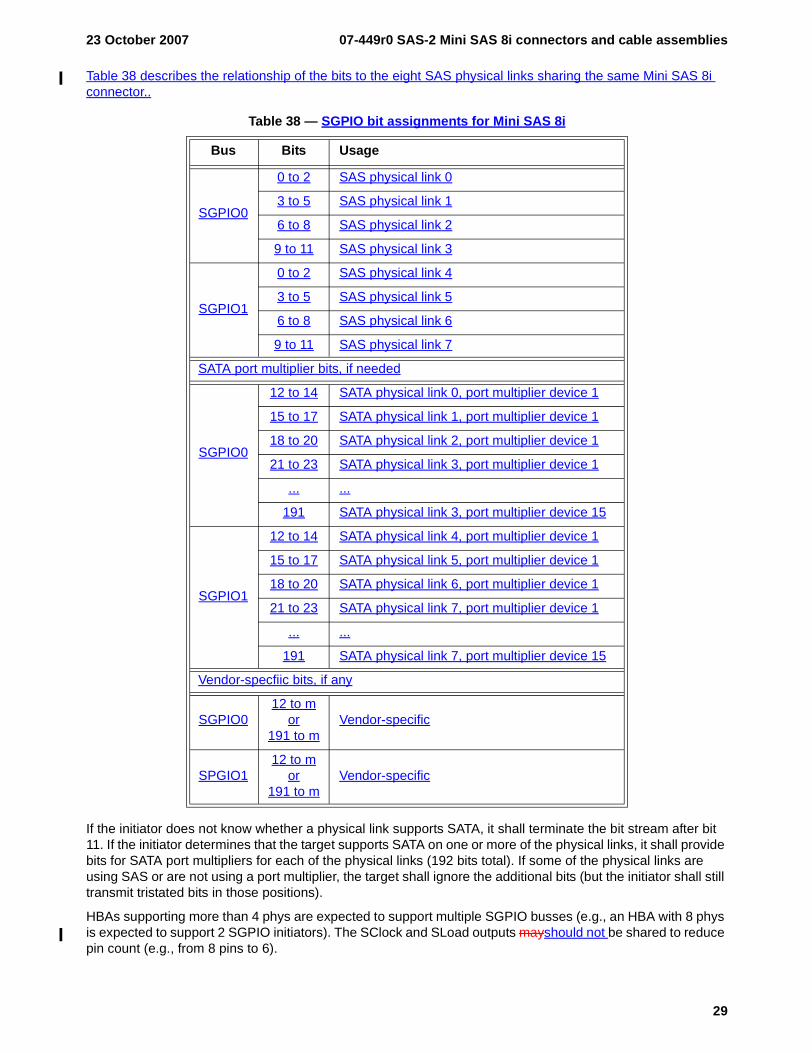
Table 38 describes the relationship of the bits to the eight SAS physical links sharing the same Mini SAS 8i connector..
If the initiator does not know whether a physical link supports SATA, it shall terminate the bit stream after bit 11. If the initiator determines that the target supports SATA on one or more of the physical links, it shall provide bits for SATA port multipliers for each of the physical links (192 bits total). If some of the physical links are using SAS or are not using a port multiplier, the target shall ignore the additional bits (but the initiator shall still transmit tristated bits in those positions).
HBAs supporting more than 4 phys are expected to support multiple SGPIO busses (e.g., an HBA with 8 phys is expected to support 2 SGPIO initiators). The SClock and SLoad outputs mayshould not be shared to reduce pin count (e.g., from 8 pins to 6).
Table 38 — SGPIO bit assignments for Mini SAS 8i
Bus Bits Usage
SGPIO0
0 to 2 SAS physical link 0
3 to 5 SAS physical link 1
6 to 8 SAS physical link 2
9 to 11 SAS physical link 3
SGPIO1
0 to 2 SAS physical link 4
3 to 5 SAS physical link 5
6 to 8 SAS physical link 6
9 to 11 SAS physical link 7
SATA port multiplier bits, if needed
SGPIO0
12 to 14 SATA physical link 0, port multiplier device 1
15 to 17 SATA physical link 1, port multiplier device 1
18 to 20 SATA physical link 2, port multiplier device 1
21 to 23 SATA physical link 3, port multiplier device 1
... ...
191 SATA physical link 3, port multiplier device 15
SGPIO1
12 to 14 SATA physical link 4, port multiplier device 1
15 to 17 SATA physical link 5, port multiplier device 1
18 to 20 SATA physical link 6, port multiplier device 1
21 to 23 SATA physical link 7, port multiplier device 1
... ...
191 SATA physical link 7, port multiplier device 15
Vendor-specfiic bits, if any
SGPIO012 to m
or191 to m
Vendor-specific
SPGIO112 to m
or191 to m
Vendor-specific