Embed Size (px)
Citation preview
PERFORMANCE OF CATHODIC PREVENTION SYSTEM OF SYDNEY OPERA HOUSE UNDERBROADWALK AFTER 10 YEARS OF OPERATION
Atef Cheaitani Savcor ART Pty Ltd
Level 13, 132 Arthur St North Sydney NSW 2060 Australia
Pietro Pedeferri
Politecnico Di Milano Piazza L. Da Vinci 32
Milano 20133 Italy
Bruno Bazzoni Cescor
Via Maniago 12 Milano 20134 Italy
Philip Karajayli
Savcor ART Pty Ltd Level 13, 132 Arthur St
North Sydney NSW 2060 Australia
Ray Dick Sydney Opera House
Bennelong Point Sydney NSW 2000 Australia
ABSTRACT
Cathodic prevention (CPrev) of reinforced concrete structures is used to improve the corrosion resistance of reinforcement for marine structures that are expected to suffer from chloride-induced corrosion during their service life. As a part of a major rehabilitation programme to the Sydney Opera House during 1995-1996, a CPrev system was installed to the reinforced concrete pre-cast elements of the Western Underbroadwalk of the Sydney Opera House. This paper will assess the cathodic prevention system performance after nearly 10 years of operation and will make a comparison between the designed and operating cathodic prevention current density of the system. Keywords: Concrete, corrosion, cathodic, prevention, anode
1

INTRODUCTION Cathodic Prevention (CPrev) is a proven electrochemical technique used in steel reinforced concrete structures to prevent the onset of corrosion caused by environmental chloride contamination. CPrev is used to improve the durability and service life of the structure and reduce maintenance costs in the long-term. It may be used with other compatible advances in concrete technology such as high performance concrete mixes, to further increase the durability of the structure in severe environments. As a part of a major rehabilitation programme to the Sydney Opera House Under Broadwalk in 1995-96, new reinforced concrete pre-cast sections were installed to replace sections that had deteriorated due to chloride-induced corrosion of the reinforcement. As part of these construction works a CPrev system was installed to these new precast elements, as they were at a very high risk of chloride contamination. Sections of the precast elements are in the dry atmospheric zone while other sections are subject to saltwater splashing at high tide each day and immersion at very high tides. The CPrev system was installed to 18 pre-cast A-Frames, 17 mid span ties and 17 pre-cast walkway sections of various lengths. The precast elements contain prestressing steel, and the avoidance of overprotection was a major consideration in the design and control of the system. The CPrev system was installed in conjunction with a Cathodic Protection (CP) system to previously existing concrete elements that were retained in the underbroadwalk. The cathodic protection system shall not be discussed in this paper. However, a water immersed anode system installed to protect the immersed sections of existing piles has an effect on the precast elements at high tide, and this effect will be considered when discussing results. Current standards on cathodic protection in concrete provide guidelines for expected operating current densities for cathodic prevention systems of 0.2 to 2mA/m2. One of the purposes of this paper is to assess the applicability of this guideline.
CATHODIC PREVENTION BACKGROUND
In the presence of chlorides, for example on bridge decks where de-icing salts are spread, or in splash zones of marine structures, additional preventive corrosion measures must be used to guarantee service life of even a few decades. Cathodic prevention is one of these measures. Such a system was applied for the first time in Italy in 1989 as “a method of preventive maintenance of new structures that are expected to become affected by chloride contamination in the future” and to emphasize that the “aims, operating conditions, throwing power, and effects (particularly those regarding hydrogen embrittlement) of CPrev, as well as many of the engineering and economic aspects of the design, construction, monitoring and maintenance of CPrev are different from those of normal cathodic protection”, so the name of cathodic prevention was proposed2,3. This technique is based on the principle that the critical chloride threshold increases as the potential of steel decreases. The decrease of reinforced steel potential is obtained through the application of a direct current, which flows through the concrete from an anode applied on the concrete surface to the reinforcement. To understand how cathodic prevention works it is important to consider the corrosion and protection conditions, which are shown in Figure 1. If environmental conditions belong to region (A), pitting
2

corrosion is possible. In order to gain protection the potential must be brought to region (B) when pitting has not started and to region (C) to stop even active pits.
Figure 1: Evolution path of cathodic prevention4 In the same Figure 1 the typical evolution path (���) in terms of potential and chloride content of cathodic prevention is shown. The lowering of potential of new passive steel allows passivity to be maintained even when chloride content becomes higher than the critical content for non-polarized structures. Such polarization leads to conditions of imperfect passivity where pitting corrosion, although it cannot initiate, can propagate. It should therefore be emphasized that cathodic prevention has to be applied before corrosion initiates and must be maintained throughout the entire service life of the structure.
DESIGN CONCEPT Materials Mesh ribbon anode LIDA®(1) Grid was used as the anode material throughout. The specifications of the mesh ribbon anode grid are as follows: • Width: 20 mm • Thickness: 0.5 mm • Current output: 5.5 mA/m This patented CPrev system involves the use of mesh ribbon anode grid attached onto the reinforcing cage with specially designed insulating cementitious material prior to pouring. The anode grid assembly for the precast elements is made of an array of parallel mesh ribbon anode grids supported by the composite cementitious spacer above which the anode elements are secured by means of plastic fixings. The assembly is positioned on the reinforcing steel and fixed by plastic ties. A titanium bus bar is welded to each anode strip to connect them together. The main characteristics of this assembly is that by varying the degree of expansion, the width and the spacing between the parallel strips, the (1) LIDA is a trademark of Oronzio De Nora SA Switzerland.
3

current output of the anode assembly can be easily varied to match the variations of the steel density of the concrete structure1. A current density of 10 mA/m2 was adopted for the design, with a maximum anode spacing of 250 mm. Electrical Zoning When selecting electrical zones, the following considerations were taken into account: 1) The different environmental conditions of the elements to be protected such as tidal and
atmospheric zones. 2) Size of power supply units. 3) Geometry of the structure, The system was divided into three zones as shown in Table 1 and Figure 2:
Table 1: Electrical Zoning Description
Zone Element Environment 6 A-Frame and Tie Beam Atmospheric 7 A-Frame Base Tidal/Splash 8 Walkway Tidal/Splash
The structure was divided into four sections, A, B, C and D. Within each section a substation is installed (total of 4 substations) with a separate DC power supply for each zone of the system1.
Figure 2: Electrical Zoning of System Monitoring The system contained a total of 35 embedded reference electrodes. The type of electrodes used was Silver/Silver Chloride (Ag/AgCl) and mixed metal oxide activated titanium electrodes suitable for long-term use in concrete. As a part of incorporating the new A-frames, tie beams and walkways to the existing structure, prestressing bars were used in the construction of the new reinforced concrete precast elements.
Zone 6 Zone 6
Zone 7
Zone 8
4

As a result of the tidal variation, these elements were subject to combined CPrev current from the embedded grid anode system and from the water anode system installed nearby to protect the piles supporting the western underbroadwalk. In order to avoid the potential overprotection conditions, a special shielding detail was adopted for the prestressing bars. In addition to the application of the shielding detail, some of the reference electrodes were placed in selected locations near the prestressing bars particularly for overprotection monitoring purposes. Protection Criteria Australian Standard AS2832.55 provides the following protection criteria for cathodic protection of steel in concrete structures. No instant off steel/concrete potential shall be more negative than –1100 mV for plain reinforcing steel or more negative than –900 mV for prestressing steel with respect to Ag/AgCl/0.5M KCl. Adjustment shall be based on meeting one of the following criteria: (a) A potential decay criterion. A potential decay over a maximum of 24 h of at least 100 mV from
instant off. (b) Extended potential decay criterion. A potential decay over a maximum of 72h of at least 100 mV
from the instant off potential subject to a continuing decay and the use of reference electrodes (not potential decay sensors) for the measurement extended beyond 24 h.
(c) Absolute potential criterion. An instant off potential more negative than –720 mV with respect to
Ag/AgCl/0.5M KCl. (d) Absolute passive criterion. A fully depolarised potential, or a potential which is continuing to
depolarise over a maximum of 72 h after the cathodic protection system has been switched off, which is consistently less negative than –150 mV with respect to Ag/AgCl/0.5M KCl.
Both criteria (c) and (d) assess the system based on absolute values of the measured reading. These criteria need to be used with caution, especially with systems of this age, as the potential of the reference electrode is likely to shift with time. Calibration of references is required to obtain an accurate absolute value, which is very difficult for references in concrete. Criteria that do not rely on absolute value criterion, such as the 100 mV shift, are more reliable when using references of this age, and shall be used for the purposes of this paper.
INSTALLATION The total concrete area of cathodic prevention application is 742 m2. A brief description of the installation carried out in 1995-96 is provided below. Reinforcing bars were welded together within each element to ensure that electrical continuity exists between them. An assembly of grid anode/cementitious spacers was delivered to site and fixed to the reinforcement cage using plastic ties. Conductor bars were spot welded to strip anodes and anode and steel connections were established for each precast element. Reference electrodes were fixed to the steel cages by means of plastic ties. Continuity testing of steel bars and short circuit testing between rebar and anode was carried out prior, during and after concrete application. Each precast element was subject to steam curing for 12 hours and then delivered to site. As a part of the testing procedure of precast elements, fixed current was
5

applied to the steel/anode circuit for each precast element. Change of steel potential with respect to embedded reference electrodes or external reference electrodes on the concrete surface were measured. For each type of precast element (walkway, A Frame and mid span tie), extensive potential mapping was undertaken in order to check current distribution and for design verification purposes. A total of 18 A Frames, 17 walkways and 17 mid span ties were cast and delivered to site for installation over a period of approximately 6 months. These new elements replaced the old elements, which were cut out and removed from site due to excessive deterioration problems. All cables from the precast elements were terminated to the 4 substations located along the western underbroadwalk1. System commissioning in 1996 verified all components of the system were operating satisfactorily.
MONITORING DATA The system was monitored at 6-monthly intervals since 1996. The results collected during each monitoring session includes: • “As Found” Current and Voltage measurements • Steel reinforcement potentials to each reference electrode with the system switched on (CP On) • Steel reinforcement potentials to each reference electrode free of voltage gradient error (CP
Instant Off). This measurement is taken 0.1-1s after the system is switched off, which allows measurement of the actual potential immediately prior to depolarisation of the steel.
• Steel reinforcement potential to each reference electrode after the system has been switched off for 24 hours (24 hr Off)
• The “24 hr Decay” potential is then calculated for each reference electrode as follows: 24 hr Decay Potential = 24 hr Off Potential – CP Instant Off Potential
• Adjusted current and voltage values. In 2004-05 a comprehensive audit of the system was undertaken. The following additional information was obtained: • Reference electrode audit to identify faulty or unstable references • Measurement of 24 hr Off and 72 hr Off steel potentials to permanent reference electrodes • Measurements of CP On, CP Instant Off, 24 hr Off and 72 hr Off steel potentials using a portable
Cu/CuSO4 reference electrode on all precast elements. These tests were performed to confirm protection was being maintained on all pre-cast elements (including those that do not have references installed) and to verify permanent reference electrode readings.
Monitoring data since 1996 has been collated in order to assess the overall performance of the system over its operational life. A sample of the data is presented in this paper for discussion.
SYSTEM PERFORMANCE General No visible deterioration, spalling or delamination has been observed on any of the precast elements with CPrev installed. In addition, it has been verified with a portable reference electrode that each and every precast element is receiving CPrev current. Therefore, the installed system components such as anodes, conductor bar, cementitious spacer, positive connections, negative connections, cabling, junction boxes and the majority of reference electrodes are still functioning as required with no sign of significant deterioration. The four substation power supply units are generally in good condition, with only a minor number of electronics needed to be replaced over the years. Each component of the
6
system was designed to be reliable in the long-term and these results confirm the design has been adequate. The reference electrodes were tested for stability and for signs of faulty behavior. Only 17% of reference electrodes were deemed to be faulty, most of which were Ag/AgCl type references. These references were excluded from future testing. System Control The CP Instant Off potential of the reinforcement measured using the embedded reference electrodes and the CP Instant Off potential of reinforcement measured using an external reference electrode on the concrete surfaces of the precast elements receiving CPrev were maintained below the level that can cause hydrogen evolution due to the prevention current. The power supply units were operating under constant voltage. This confirms that CPrev can be used safely in prestressed concrete structures providing the system is operating in voltage control mode and the maximum operating voltage is limited for the system operation. The main reason for this is the low current required under cathodic prevention conditions.
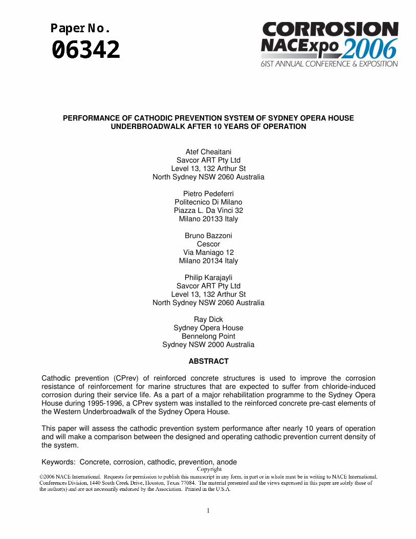
MONITORING DATA Figures 3 to 5 below present the 24 hr potential decay values for a sample of the permanent reference electrodes since 1996. The results indicate that in the majority of cases the decay was greater than 100mV, indicating full protection had been maintained. Figure 3: Zone 6 Reference Electrode Potential Decays since 1996 Figure 4: Zone 7 Reference Electrode Potential Decays since 1996
Figure 5: Zone 8 Reference Electrode Potential Decays since 1996 The most recent monitoring of the system was conducted in September 2005, and a sample of the results is presented in Table 2.
0
50
100
150
200
250
300
350
400
450
500
1996 1998 2000 2004 2005
Year
Po
ten
tial D
ecay
(mV
)
Ref 1
Ref 2
Ref 3
Ref 4
0
50
100
150
200
250
300
350
400
1996 1998 2000 2004 2005
Year
Pot
entia
l D
ecay
(mV
)
Ref 4
Ref 5
Ref 6
Ref 7
0
50
100
150
200
250
300
350
400
450
1996 1998 2000 2004 2005
Year
Pot
entia
l Dec
ay (m
V)
Ref 9
Ref 10
Ref 11
Ref 12
7

Table 2: Permanent Embedded Reference Electrode Monitoring Results Potential of steel reinforcement (mV)
Reference Type Location Zone CP ON CP Instant Off 24 hr Off 24 hr Decay
A61 Titanium A-Frame 6 -291 -272 -14 258 A62 Ag/AgCl A-Frame 6 -132 -122 +25 147 A71 Titanium A-Frame Base 7 -334 -316 -93 223 A72 Ag/AgCl A-Frame Base 7 -408 -394 -215 179 W81 Titanium Walkway 8 -419 -408 -305 103 W82 Ag/AgCl Walkway 8 -471 -481 -335 146
The reference electrodes were embedded only in selected precast concrete elements. In order to ensure that all the elements of the structures are receiving CPrev current, external potential mapping testing using a calibrated Copper/Copper Sulphate reference electrode was performed for each element of the structure. This testing includes measuring at selected pre-determined locations on the concrete surfaces the CP On potential, CP Instant off potential and the 24hr and 72 hr Off potentials. The results of the test suggest that the cathodic prevention current is providing full protection to all the elements of the structure. A sample of the results is presented in Table 3 for all zones at various locations.
Table 3: Potential of Steel Reinforcement measured by external reference electrode Potential vs Portable Cu/CuSO4 (mV)
Element Zone CP ON
CP Instant
Off
24 Hour Off
24 Hr Decay
72 Hour Off
72 Hr Decay
A-Frame 6 -925 -383 -46 337 3 386 Mid-Tie Beam 6 -419 -308 -50 258 3 311 A-Frame 6 -950 -436 -128 308 -69 367 Mid-Tie Beam 6 -483 -462 -64 398 16 478 A-Frame (sub A) 6 -492 -384 -62 322 29 413 Mid-Tie Beam 6 -635 -479 -104 375 -27 452 A-Frame 6 -767 -413 -134 279 -74 339 Mid-Tie Beam 6 -402 -284 -46 238 33 317 A-Frame 6 -887 -459 -244 215 -140 319 A-Frame Base 7 -610 -503 -337 166 -352 151 A-Frame Base 7 -663 -600 -430 170 -495 105 A-Frame Base 7 -815 -673 -444 229 -410 263 A-Frame Base 7 -768 -579 -418 161 -411 168 A-Frame Base 7 -730 -576 -368 208 -354 222 A-Frame Base 7 -843 -633 -408 225 -325 308 Walkway 8 -684 -603 -394 209 -325 278 Walkway 8 -710 -635 -415 220 -456 179 Walkway 8 -860 -700 -468 232 -574 126 Walkway 8 -964 -784 -675 109 -485 299 Walkway 8 -743 -700 -545 155 -495 205 Walkway 8 -920 -860 -723 137 -619 241 The decay values measured by both permanent and portable reference electrodes indicate full protection is being maintained on the structure with the present current and voltage outputs. The results can be used to confirm that the operating currents are satisfactory for protection, although not excessive.
8
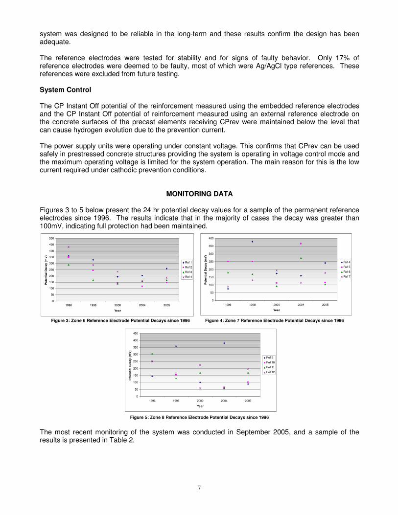
Operating Current Density Using the present operating current, the present operating current density was calculated in terms of current per metre square of steel reinforcement surface area (mA/m2). The current density for each zone is presented in Table 4.
Table 4: Operating Current Density for each Zone
Zone Substation Operating Current Density (mA/m2)
6 A 4.1 6 B 2.1 6 C 3.1 6 D 3.4
Average 3.2 7 A 3.1 7 B 3.0 7 C 4.2 7 D 3.0
Average 3.3 8 A 1.0 8 B 1.4 8 C 1.1 8 D 0.8
Average 1.1 It must be noted here that Zones 7 and 8 are affected by the tide and thus are subject to additional protection by the water anodes that are protecting the piles nearby. The exposure of zone 8 (walkways) to the water anode system influence is much greater than zone 7, so for this reason it can be assumed that the operating current density of zones 6 and 7 would be the typical current density for cathodic prevention. Zone 8 of the system was greatly influenced by the water anode system and the average operating current density recorded (1.1 mA/m2) is considered to be only the partial current density required to achieve corrosion prevention in this case. The operating current density range for Zone 6 and 7 is 2.1 - 4.2 mA/m2, and the average is 3.3 mA/m2. An analysis of the average current densities from 1996 to 2005 was then made to assess the changes made to the system. A sample of the data is shown in Figure 6 below. The very high current densities in 1996 were only used for commissioning the system, as the optimum initial current requirement was unknown at this stage. Major adjustments were made over the years to optimise the required current output.
9

Figure 6: Average Current Densities from 1996 to 2005 A maximum spacing of 250mm between the ribbon anodes was adopted for the system design. In the majority of cases, the actual design current density was much higher than 10 mA/m2 in order to comply with the maximum adopted anode spacing requirement.
CONCLUSIONS The cathodic prevention system has been operating successfully for almost 10 years. The physical components of the system in a relatively harsh environment have a proven durability. The potential of the steel reinforcement, as measured by both portable and permanent reference electrodes, has been maintained at protected levels across the structure, with only minimal current. The low operating currents measured in 2004-05 are considered adequate operating currents of the system. The operating current density of the system is in the range 2 to 5 mA/m2. This value may only be relevant for similar structures in a similar environment. That is, Zone 6 is in an atmospheric zone but within very close proximity to seawater (within 0.5 to 2m) and Zone 7 is in a splash/tidal zone. Australian and European Standards5,6 for cathodic protection in concrete include guidelines on current provision when designing cathodic protection/prevention systems: “Typical cathodic prevention current densities range between 0.2 mA/m2 and 2 mA/m2”.5 These figures are based on laboratory tests and field experiences mainly referring to cathodic prevention of steel reinforcement in atmospherically exposed concrete, in particular decks and piles of bridges and viaducts.8-11 The measured current densities for atmospherically exposed elements at the Sydney Opera House indicate the current density requirement is generally higher than these figures. When designing cathodic prevention systems in marine environments without the benefit of a trial or pilot system, a more conservative approach should be taken when considering the operating current density. Additional data from other CPrev systems that have been operating in the long term would be useful in further determining a general guideline for current densities. Based on the information presented in this paper, a value of 10 mA/m2 current density is an adequate suggested figure to use
0.0
5.0
10.0
15.0
20.0
25.0
1996 1997 1998 1999 2000 2001 2002 2003 2004 2005
Year
Cur
rent
Den
sity
, mA
/m2
Zone 6Zone 7Zone 8
10

when designing CPrev systems for uncoated steel in atmospherically-exposed concrete in marine environments. Cathodic prevention can be used safely for the protection of prestressed concrete structures that are expected to suffer from chloride induced corrosion during the service life of the structure. The required prevention current is relatively very low and hydrogen evolution is unlikely if the system is properly designed and monitored. Cathodic prevention is a very cost effective solution. The maintenance and monitoring costs and the power consumption costs to operate CPrev systems is low. The yearly maintenance and monitoring cost for the prevention system was considered to be in the range of 1.0-1.5 % of the overall CPrev installation contract value. The power consumption cost for operating the system is considered to be negligible. The spacing of the ribbon anodes in this installation was based on a maximum spacing of 250 mm, although current requirements based on 10 mA/m2 may allow double or triple this spacing for some reinforced concrete elements with minimal reinforcement. A larger anode spacing has been used in other CPrev projects using similar anodes. More research is required in this area in order to determine the maximum anode spacing that can be applied without affecting a proper cathodic prevention current distribution to the embedded reinforcement. Larger anode spacing may contribute to lowering the CPrev initial cost. The cathodic prevention system operating at the Sydney Opera House has proven to be successful in preventing corrosion, with minimal maintenance in the medium to long-term. Future monitoring shall assess the longer-term performance of the system. Cathodic prevention is an ideal technology for extending the service life and reducing maintenance costs of reinforced concrete marine structures.
REFERENCES 1. M. Tettamanti, A. Rossini; A. Cheaitani; “Cathodic Prevention and Cathodic Protection of New and
Existing Concrete Elements at the Sydney Opera House”, Corrosion/97, Paper No. 255, NACE, 1997.
2. Pedeferri, P., “Cathodic Protection of New Concrete Constructions”, Proc. Int. Conf. on “Structural
Improvement through Corrosion Protection of Reinforced Concrete”, Institute of Corrosion, London, 1992.
3. L. Lazzari, P.Pedeferri, ”Cathodic Protection”, Polipress, Milano, 2005. 4. Pedeferri, P., “Cathodic Protection and Cathodic Prevention”, Construction and Building Materials,
Vol. 10, No. 5, 1996, pp. 391-402. 5. Australian Standard, AS2832.5-2002, “Cathodic Protection of Metals, Part 5: Steel in Concrete
Structures”, Standards Australia, 2002. 6. European Standard EN12696, “Cathodic Protection of Steel in Concrete”, European Committee
For Standardization, March 2000. 7. M.A. Biagioli,M. Tettamanti., A. Rossini, L. Cassar, G. Tognon, G. Farniliari., “Anodic system for
cathodic protection of new reinforced concrete structures: laboratory test”CORROSION/93, paper 321 (HOUSTON TX, NACE International, 1993).
11

8. L. Bertolini, “Cathodic prevention”, Proc. COST 521, Workshop, 28-31 August, D. Sloan, P. A. M. Basheer (Eds.), The Queen’s University Belfast, 2000.
9. L. Bertolini, F. Bolzoni, T. Pastore, P. Pedeferri, “Three year tests on cathodic prevention of reinforced concrete structures”, Int. Conf. Corrosion/97, paper 244, NACE, Houston, 1997.
10. L. Bertolini, M. Gastaldi, T. Pastore, P. Pedeferri, E. Redaelli, “Cathodic protection of steel in
concrete and cathodic prevention”, Final project report I5, COST 521, Luxembourg, 18-19 February 2002.
11. A. Bazzoni, B. Bazzoni, L. Lazzari, L. Bertolini, P. Pedeferri, “Field Application of Cathodic
Prevention on Reinforced Concrete Structures”, NACE Corrosion 96 Conference, paper n. 312, Houston, TX, 1996.
12


![cathodic protection in practise · 2 [CATHODIC PROTECTION/BM] CATHODIC PROTECTION P E FRANCIS 1 INTRODUCTION The first practical use of cathodic protection is generally credited to](https://img.pdfslide.us/doc/110x75/5ace93c87f8b9ae2138b87e4/cathodic-protection-in-cathodic-protectionbm-cathodic-protection-p-e-francis.jpg)