Embed Size (px)
Citation preview
FLMTA/FLMFA GPS/Cellular/Wi-Fi
Antenna
-
3F-11, 130, Jian-Kang Rd., Chung Ho, Taiwan, R.O.C. Tel: 886-2-32349610 Fax: 886-2-82211522 E-Mail: [email protected]
www.haicom.com.tw
Haicom Electronics CORP.
Page 1 of 11
1. Electrical Specification ........................................................................................................... 2 1.1 Electrical Date............................................................................................................. 2
2. Mechanical Specification........................................................................................................ 2 2.1 Mechanical Data ......................................................................................................... 2 2.2 Dimensions ................................................................................................................. 3 2.3 Connectors .................................................................................................................. 3 2.4 Installation Location ................................................................................................... 4 2.5 RF Cable ..................................................................................................................... 4
RG-174/U........................................................................................................................ 4 3. Environmental Specification................................................................................................... 5 4. Ordering Information .............................................................................................................. 5
4.1 Model NO. .................................................................................................................. 5 4.2 Housing Type .............................................................................................................. 5 4.3 Connector Type ........................................................................................................... 5 4.4 Cable Type .................................................................................................................. 6 4.5 Cable Length............................................................................................................... 6 4.6 Label Type................................................................................................................... 7 4.7 Package Type .............................................................................................................. 7
5. Appendix................................................................................................................................. 8 5.1 Appendix 1:FLMTA/FLMFA ROSH Report ........................................................... 8 5.2 Appendix 2:Gain Pattern and VSWR ...................................................................... 9
Page 2 of 11
1. Electrical Specification
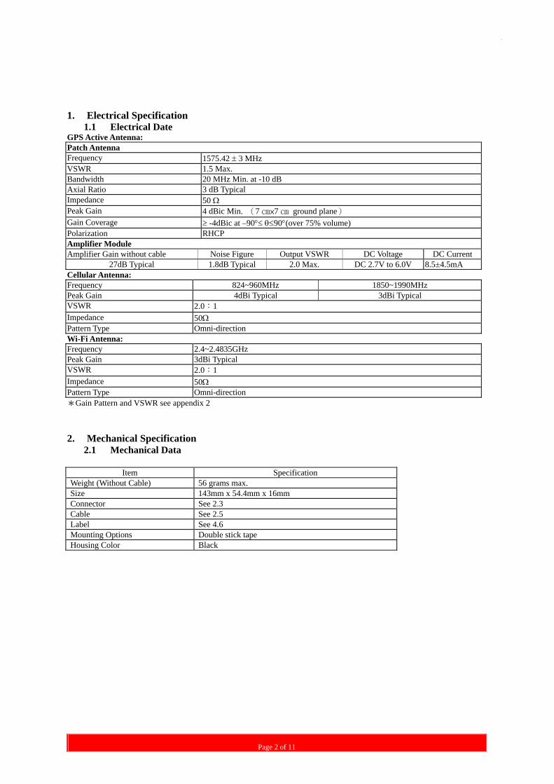
1.1 Electrical Date GPS Active Antenna: Patch Antenna Frequency 1575.42 ± 3 MHz VSWR 1.5 Max. Bandwidth 20 MHz Min. at -10 dB Axial Ratio 3 dB Typical Impedance 50 Ω Peak Gain 4 dBic Min. (7 ×7 ground plane) Gain Coverage ≥ -4dBic at –90°≤ θ≤90°(over 75% volume) Polarization RHCP Amplifier Module Amplifier Gain without cable Noise Figure Output VSWR DC Voltage DC Current
27dB Typical 1.8dB Typical 2.0 Max. DC 2.7V to 6.0V 8.5±4.5mA Cellular Antenna: Frequency 824~960MHz 1850~1990MHz Peak Gain 4dBi Typical 3dBi Typical VSWR 2.0:1 Impedance 50Ω Pattern Type Omni-direction Wi-Fi Antenna: Frequency 2.4~2.4835GHz Peak Gain 3dBi Typical VSWR 2.0:1 Impedance 50Ω Pattern Type Omni-direction *Gain Pattern and VSWR see appendix 2 2. Mechanical Specification
2.1 Mechanical Data
Item Specification Weight (Without Cable) 56 grams max. Size 143mm x 54.4mm x 16mm Connector See 2.3 Cable See 2.5 Label See 4.6 Mounting Options Double stick tape Housing Color Black
Page 3 of 11
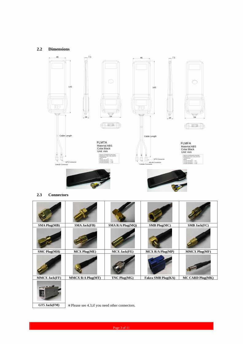
2.2 Dimensions
Cable Length
GPS ConnectorCellular Connector
C G
54
46
143
FLMTA
Unit: mm
Material:ABSColar:Black
16
UNLESS OTHERWISE SPECIFIEDDIMENSIONS ARE IN MILLIMETERTOLERANCES:ANGLE ± 1°1 PLACE DECIMALS ± 0.22 PLACE DECIMALS ± 0.153 PLACE DECIMALS ± 0.05
7.1
7.1
UNLESS OTHERWISE SPECIFIEDDIMENSIONS ARE IN MILLIMETERTOLERANCES:ANGLE ± 1°1 PLACE DECIMALS ± 0.22 PLACE DECIMALS ± 0.153 PLACE DECIMALS ± 0.05
16
Colar:BlackMaterial:ABS
Unit: mm
FLMFA
143
46
54
Cellular Connector
GPS Connector
Cable Length
WLAN Connector
WC G
2.3 Connectors
SMA Plug(MB) SMA Jack(FB) SMA R/A Plug(MQ) SMB Plug(MC) SMB Jack(FC)
SMC Plug(MH) MCX Plug(ME) MCX Jack(FE) MCX R/A Plug(MP) MMCX Plug(MF)
MMCX Jack(FF) MMCX R/A Plug(MT) TNC Plug(MG) Fakra SMB Plug(KA) MC CARD Plug(MK)
GT5 Jack(FM) *Please see 4.3,if you need other connectors.
Page 4 of 11
GPS
DOUBLE STICK TAPE or
VELCRO TAPE
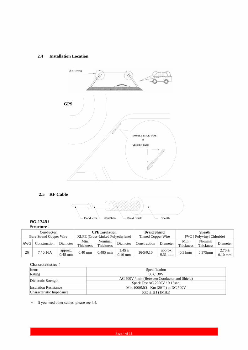
2.4 Installation Location
2.5 RF Cable
SheathBraid ShieldConductor Insulation RG-174/U Structure:
Conductor Bare Strand Copper Wire
CPE Insulation XLPE (Cross-Linked Polyethylene)
Braid Shield Tinned Copper Wire
Sheath PVC ( Polyvinyl Chloride)
AWG Construction Diameter Min. Thickness
NominalThickness Diameter Construction Diameter Min.
Thickness Nominal
Thickness Diameter
26 7 / 0.16A approx. 0.48 mm 0.40 mm 0.485 mm 1.45 ±
0.10 mm 16/5/0.10 approx.0.31 mm 0.31mm 0.375mm 2.70 ±
0.10 mm Characteristics: Items Specification Rating 80 30V
AC 500V / min.(Between Conductor and Shield) Dielectric Strength Spark Test AC 2000V / 0.15sec. Insulation Resistance Min.1000MΩ - Km (20 ) at DC 500V Characteristic Impedance 50Ω ± 5Ω (1MHz) * If you need other cables, please see 4.4.

Page 5 of 11
3. Environmental Specification Items Specification Working Temperature -40°C< T< +85°C Storage Temperature -50°C< T< +85°C Humidity 95%~100% RH 4. Ordering Information Item NO.
XXXXX-SXXXXXXXXX4.1 Model NO.
4.2 Housing Type
4.3 Connector Type
4.7 Package Type
4.6 Label Type
4.5 Cable Length
4.4 Cable Type
4.1 Model NO. Item NO.:xxxxx-sxxxxxxxxx
4.2 Housing Type Item NO.:xxxxx-sxxxxxxxxx
NO. Specification
SB Black
* ”S” means ROSH, please see appendix 1
4.3 Connector Type Item NO.:xxxxx-sxxxxxxxxx
Model NO. GPS 1575.42 ± 3 MHz
Cellular 824~960MHz
1850~1990MHz
Wi-Fi 2.4~2.4835GHz
FLMTA √ √ FLMFA √ √ √
NO. Specification (GPS Connector + Cellular Connector ) NO. Specification
(GPS Connector + Cellular Connector ) DA SMA plug + TNC plug DB SMA plug + SMA plug DC MCX plug + SMA plug DD SMA plug + Mini UHF plug
DE SMB plug + SMA plug DF FAKRA SMB plug(Blue) + FAKRA SMB plug(Bordeaux Violet)
FF FAKRA SMB jack(Blue) + FAKRA SMB jack(Bordeaux Violet) DG MMCX plug + MMCX plug
DJ SMA plug + BNC plug DK BNC plug + SMA plug DL MMCX R/A plug + MMCX R/A plug DM SMB plug + TNC plug DN MMCX R/A plug + SMA plug DI SMA plug + FME plug DP SMA R/A plug + SMA plug DQ SMC plug + SMA plug DR MCX plug + TNC plug DS SMA plug + FME jack DT SMA plug + SMA R/P plug DU SMA jack + SMA plug DV MMCX R/A plug + SMA plug
Page 6 of 11
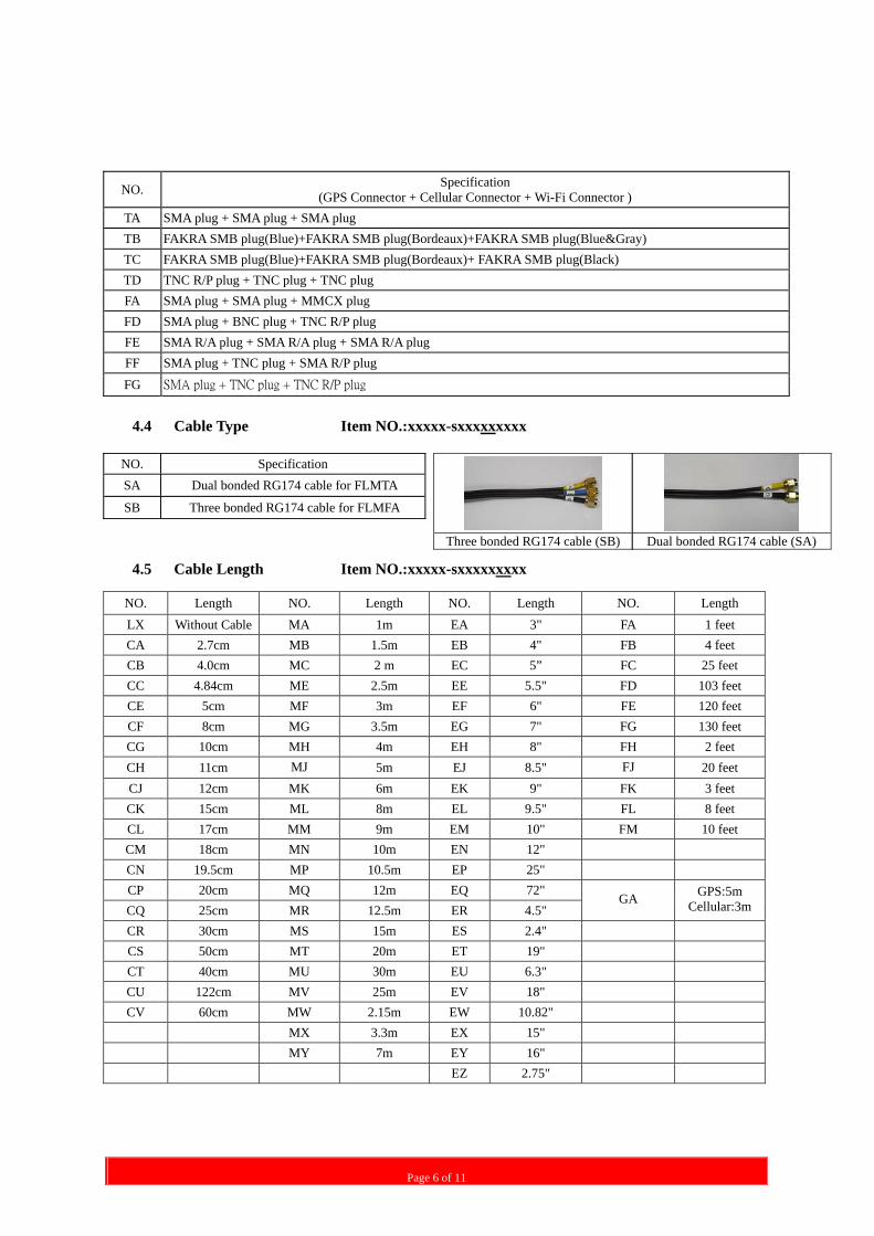
4.4 Cable Type Item NO.:xxxxx-sxxxxxxxxx
4.5 Cable Length Item NO.:xxxxx-sxxxxxxxxx
NO. Specification (GPS Connector + Cellular Connector + Wi-Fi Connector )
TA SMA plug + SMA plug + SMA plug TB FAKRA SMB plug(Blue)+FAKRA SMB plug(Bordeaux)+FAKRA SMB plug(Blue&Gray) TC FAKRA SMB plug(Blue)+FAKRA SMB plug(Bordeaux)+ FAKRA SMB plug(Black) TD TNC R/P plug + TNC plug + TNC plug FA SMA plug + SMA plug + MMCX plug FD SMA plug + BNC plug + TNC R/P plug FE SMA R/A plug + SMA R/A plug + SMA R/A plug FF SMA plug + TNC plug + SMA R/P plug FG SMA plug + TNC plug + TNC R/P plug
NO. Specification SA Dual bonded RG174 cable for FLMTA
SB Three bonded RG174 cable for FLMFA
Three bonded RG174 cable (SB)
Dual bonded RG174 cable (SA)
NO. Length NO. Length NO. Length NO. Length LX Without Cable MA 1m EA 3" FA 1 feet CA 2.7cm MB 1.5m EB 4" FB 4 feet CB 4.0cm MC 2 m EC 5” FC 25 feet CC 4.84cm ME 2.5m EE 5.5" FD 103 feet CE 5cm MF 3m EF 6" FE 120 feet CF 8cm MG 3.5m EG 7" FG 130 feet CG 10cm MH 4m EH 8" FH 2 feet CH 11cm MJ 5m EJ 8.5" FJ 20 feet CJ 12cm MK 6m EK 9" FK 3 feet CK 15cm ML 8m EL 9.5" FL 8 feet CL 17cm MM 9m EM 10" FM 10 feet CM 18cm MN 10m EN 12" CN 19.5cm MP 10.5m EP 25" CP 20cm MQ 12m EQ 72" CQ 25cm MR 12.5m ER 4.5"
GA GPS:5m Cellular:3m
CR 30cm MS 15m ES 2.4" CS 50cm MT 20m ET 19" CT 40cm MU 30m EU 6.3" CU 122cm MV 25m EV 18" CV 60cm MW 2.15m EW 10.82"
MX 3.3m EX 15" MY 7m EY 16" EZ 2.75"
Page 7 of 11
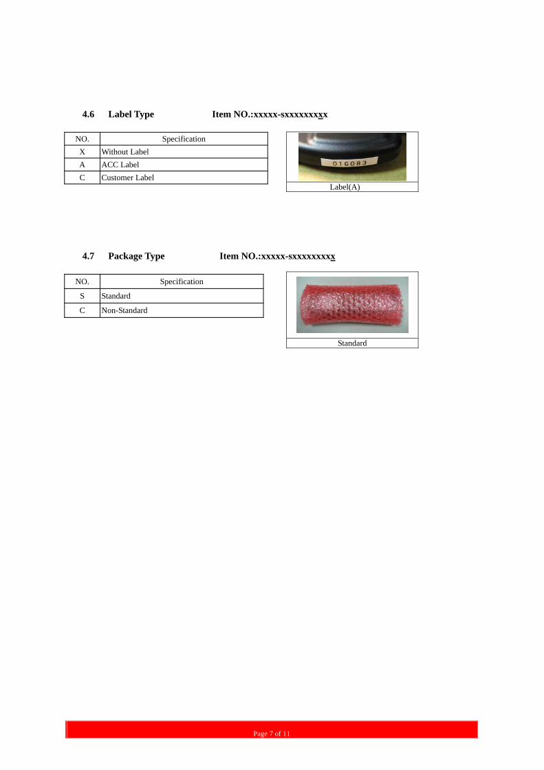
4.6 Label Type Item NO.:xxxxx-sxxxxxxxxx
NO. Specification X Without Label A ACC Label C Customer Label
4.7 Package Type Item NO.:xxxxx-sxxxxxxxxx
NO. Specification
S Standard
C Non-Standard
Label(A)
Standard
Page 8 of 11
5. Appendix
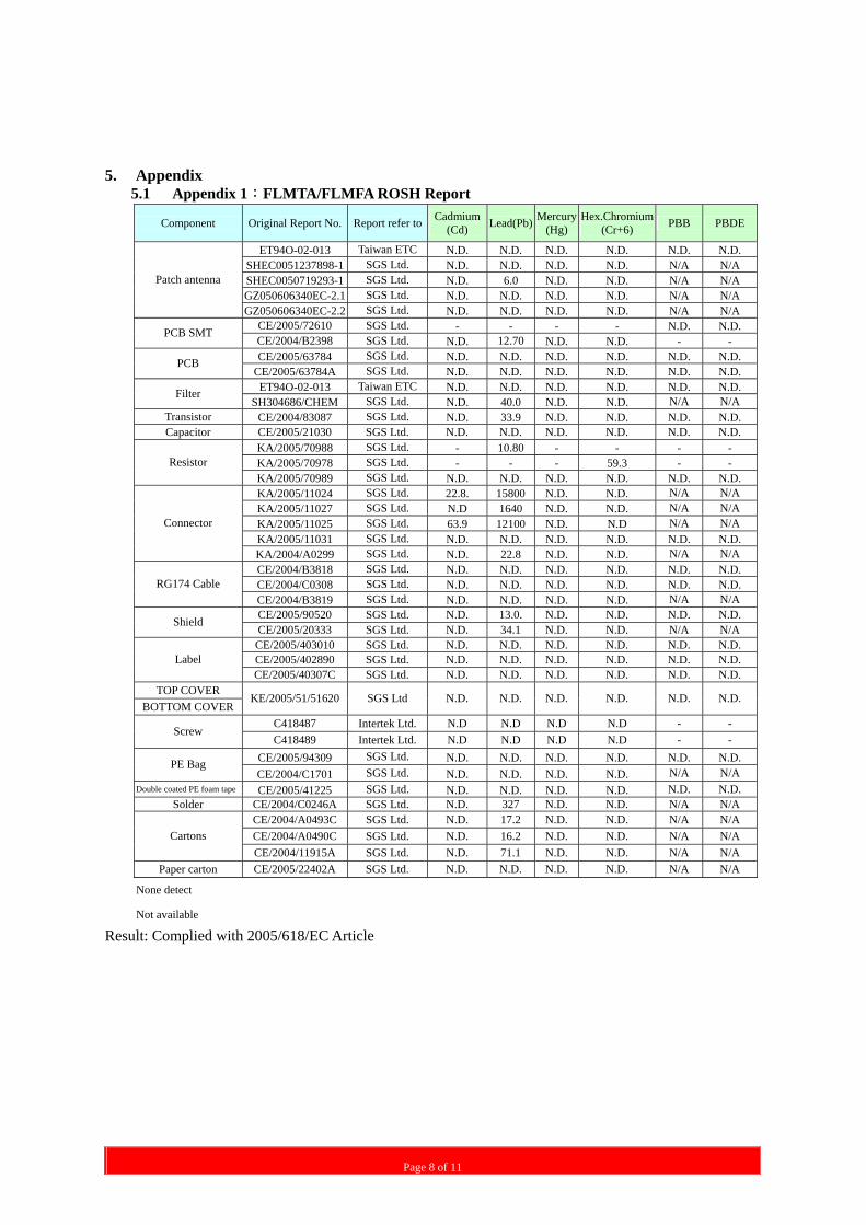
5.1 Appendix 1:FLMTA/FLMFA ROSH Report
Component Original Report No. Report refer to Cadmium(Cd) Lead(Pb) Mercury
(Hg)Hex.Chromium
(Cr+6) PBB PBDE
ET94O-02-013 Taiwan ETC N.D. N.D. N.D. N.D. N.D. N.D. SHEC0051237898-1 SGS Ltd. N.D. N.D. N.D. N.D. N/A N/A SHEC0050719293-1 SGS Ltd. N.D. 6.0 N.D. N.D. N/A N/A GZ050606340EC-2.1 SGS Ltd. N.D. N.D. N.D. N.D. N/A N/A
Patch antenna
GZ050606340EC-2.2 SGS Ltd. N.D. N.D. N.D. N.D. N/A N/A CE/2005/72610 SGS Ltd. - - - - N.D. N.D. PCB SMT CE/2004/B2398 SGS Ltd. N.D. 12.70 N.D. N.D. - - CE/2005/63784 SGS Ltd. N.D. N.D. N.D. N.D. N.D. N.D. PCB
CE/2005/63784A SGS Ltd. N.D. N.D. N.D. N.D. N.D. N.D. ET94O-02-013 Taiwan ETC N.D. N.D. N.D. N.D. N.D. N.D. Filter
SH304686/CHEM SGS Ltd. N.D. 40.0 N.D. N.D. N/A N/A Transistor CE/2004/83087 SGS Ltd. N.D. 33.9 N.D. N.D. N.D. N.D. Capacitor CE/2005/21030 SGS Ltd. N.D. N.D. N.D. N.D. N.D. N.D.
KA/2005/70988 SGS Ltd. - 10.80 - - - - KA/2005/70978 SGS Ltd. - - - 59.3 - - Resistor KA/2005/70989 SGS Ltd. N.D. N.D. N.D. N.D. N.D. N.D. KA/2005/11024 SGS Ltd. 22.8. 15800 N.D. N.D. N/A N/A KA/2005/11027 SGS Ltd. N.D 1640 N.D. N.D. N/A N/A KA/2005/11025 SGS Ltd. 63.9 12100 N.D. N.D N/A N/A KA/2005/11031 SGS Ltd. N.D. N.D. N.D. N.D. N.D. N.D.
Connector
KA/2004/A0299 SGS Ltd. N.D. 22.8 N.D. N.D. N/A N/A CE/2004/B3818 SGS Ltd. N.D. N.D. N.D. N.D. N.D. N.D. CE/2004/C0308 SGS Ltd. N.D. N.D. N.D. N.D. N.D. N.D. RG174 Cable CE/2004/B3819 SGS Ltd. N.D. N.D. N.D. N.D. N/A N/A CE/2005/90520 SGS Ltd. N.D. 13.0. N.D. N.D. N.D. N.D. Shield CE/2005/20333 SGS Ltd. N.D. 34.1 N.D. N.D. N/A N/A CE/2005/403010 SGS Ltd. N.D. N.D. N.D. N.D. N.D. N.D. CE/2005/402890 SGS Ltd. N.D. N.D. N.D. N.D. N.D. N.D. Label CE/2005/40307C SGS Ltd. N.D. N.D. N.D. N.D. N.D. N.D.
TOP COVER BOTTOM COVER
KE/2005/51/51620 SGS Ltd N.D. N.D. N.D. N.D. N.D. N.D.
C418487 Intertek Ltd. N.D N.D N.D N.D - - Screw
C418489 Intertek Ltd. N.D N.D N.D N.D - - CE/2005/94309 SGS Ltd. N.D. N.D. N.D. N.D. N.D. N.D. PE Bag CE/2004/C1701 SGS Ltd. N.D. N.D. N.D. N.D. N/A N/A
Double coated PE foam tape CE/2005/41225 SGS Ltd. N.D. N.D. N.D. N.D. N.D. N.D. Solder CE/2004/C0246A SGS Ltd. N.D. 327 N.D. N.D. N/A N/A
CE/2004/A0493C SGS Ltd. N.D. 17.2 N.D. N.D. N/A N/A CE/2004/A0490C SGS Ltd. N.D. 16.2 N.D. N.D. N/A N/A Cartons CE/2004/11915A SGS Ltd. N.D. 71.1 N.D. N.D. N/A N/A
Paper carton CE/2005/22402A SGS Ltd. N.D. N.D. N.D. N.D. N/A N/A
None detect
Not available
Result: Complied with 2005/618/EC Article
Page 9 of 11
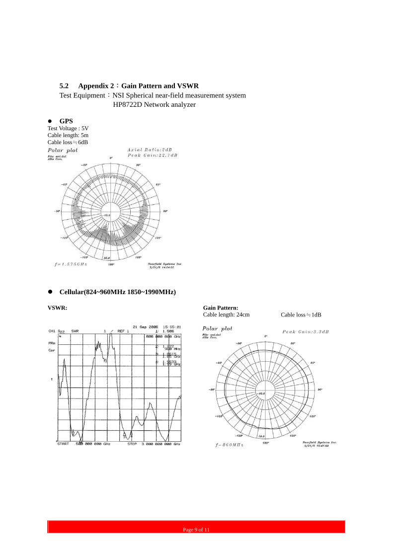
5.2 Appendix 2:Gain Pattern and VSWR Test Equipment:NSI Spherical near-field measurement system
HP8722D Network analyzer
GPS Test Voltage : 5V Cable length: 5m Cable loss≒6dB
Cellular(824~960MHz 1850~1990MHz) VSWR: Gain Pattern: Cable length: 24cm Cable loss≒1dB
Page 10 of 11
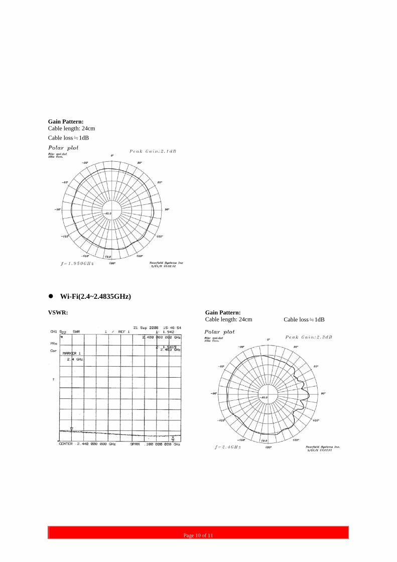
Gain Pattern: Cable length: 24cm Cable loss≒1dB
Wi-Fi(2.4~2.4835GHz) VSWR: Gain Pattern: Cable length: 24cm Cable loss≒1dB
Page 11 of 11
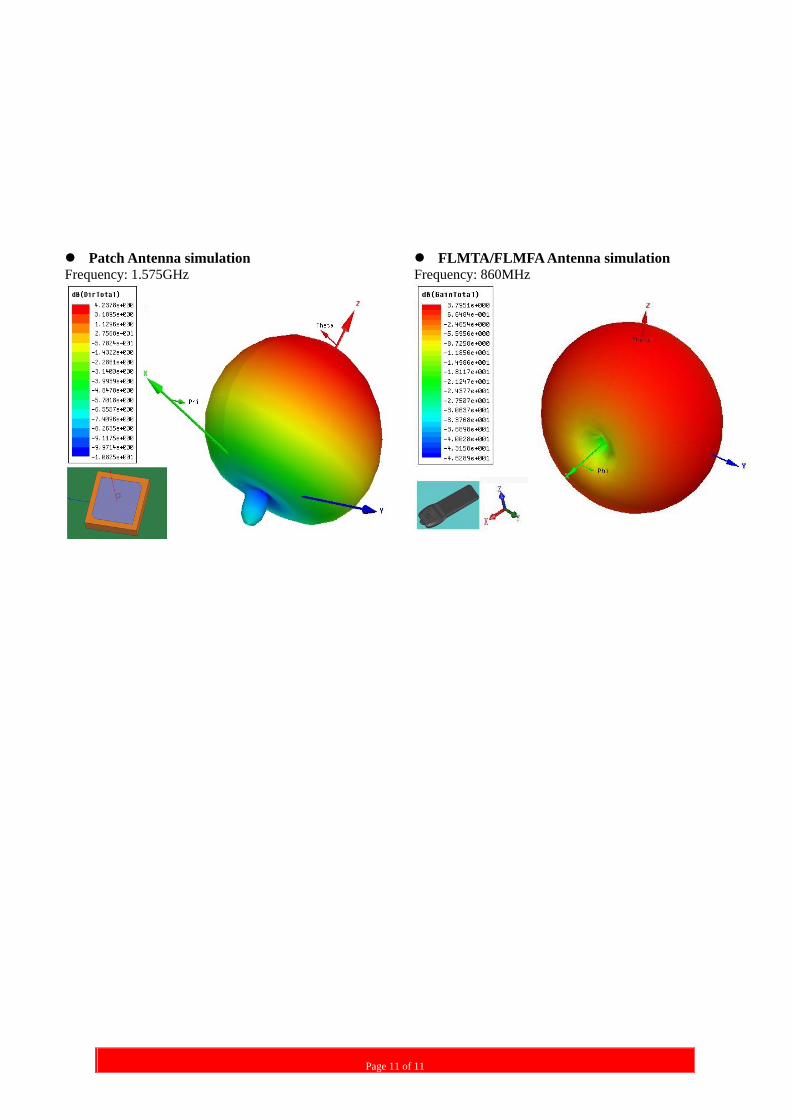
Patch Antenna simulation FLMTA/FLMFA Antenna simulation Frequency: 1.575GHz Frequency: 860MHz