Embed Size (px)
DESCRIPTION
bhbhv
Citation preview

Distributed Recovery from Network Partitioningin Movable Sensor/Actor Networks
via Controlled MobilityKemal Akkaya, Member, IEEE, Fatih Senel,
Aravind Thimmapuram, and Suleyman Uludag, Member, IEEE
Abstract—Mobility has been introduced to sensor networks through the deployment of movable nodes. In movable wireless networks,
network connectivity among the nodes is a crucial factor in order to relay data to the sink node, exchange data for collaboration, and
perform data aggregation. However, such connectivity can be lost due to a failure of one or more nodes. Even a single node failure
may partition the network, and thus, eventually reduce the quality and efficiency of the network operation. To handle this connectivity
problem, we present PADRA to detect possible partitions, and then, restore the network connectivity through controlled relocation of
movable nodes. The idea is to identify whether or not the failure of a node will cause partitioning in advance in a distributed manner. If a
partitioning is to occur, PADRA designates a failure handler to initiate the connectivity restoration process. The overall goal in this
process is to localize the scope of the recovery and minimize the overhead imposed on the nodes. We further extend PADRA to handle
multiple node failures. The approach, namely, MDAPRA strives to provide a mutual exclusion mechanism in repositioning the nodes to
restore connectivity. The effectiveness of the proposed approaches is validated through simulation experiments.
Index Terms—Movable sensors and actors, relocation, fault tolerance, connectivity, node failure, partitioning.
Ç
1 INTRODUCTION
IN recent years, there has been a growing attention indeploying heterogeneous movable nodes within the
wireless sensor networks (WSNs) for various purposes.The types of these nodes vary from small mobile motes,from Robomote [1] and [2] to powerful actors [3] which cantake certain actions. While the former has given rise todeploy Movable/Mobile Sensor Networks (MSNs) ([1], [4]),where all the sensors can move on demand in addition totheir sensing capabilities, the latter has introduced network-ing of mobile actors with static sensors called WirelessSensor and Actor Networks (WSANs) [3]. Actors in WSANsare movable units such as robots, rovers, and unmannedvehicles which can process the sensed data make decisions,and then, perform appropriate actions. The response of theactors mainly depends on its capabilities and the applica-tion. For instance, actors can be used in lifting debris tosearch for survivors, extinguishing fires, chasing anintruder, etc. Examples of WSAN applications includefacilitating/conducting Urban Search And Rescue (USAR),detecting and countering pollution in coastal areas, detec-
tion and deterring of terrorist threats to ships in ports,destruction of land and underwater mines, etc.
In both MSNs and WSANs, connectivity of the network iscrucial throughout the lifetime of the network in order tomeet the desired application-level requirements. For in-stance, in MSNs, sensors need to periodically, or in responseto a query, send their data to the sink node so that all spotsof the region can be monitored accurately. In addition, theyneed to perform aggregation/fusion on the data theyreceive from their neighbors and relay the fused informationtoward the sink. This requires that the whole network withthe sink node and sensors should be connected throughoutthe lifetime of the network. Similarly, as far as the WSANsare concerned, in most application setups, actors need tocoordinate with each other in order to share and process thesensors’ data, plan an optimal response, and pick the mostappropriate subset of actors for executing such a plan. Forinstance, in a forest monitoring application, in case of a fire,the actors should collaboratively decide the best possiblesolution in terms of the number of actors to employ, theirtraveling time, and distance to the fire spot. Again, thisprocess requires that all the actors should form andmaintain a connected interactor network at all times tobecome aware of the current states of others.
In such connected MSNs and WSANs, failure of one ormultiple nodes (i.e., sensors and actors, respectively) maycause the loss of multiple internode communication links,partition the network if alternate paths among the affectednodes are not available, and stop the actuation capabilities ofthe node if any. Such a scenario will not only hinder the nodes’collaboration but also has very negative consequences on theconsidered applications. Therefore, MSNs and WSANsshould be able to tolerate the failure of mobile nodes andself-recover from them in a distributed, timely, and energy-efficient manner: First, the recovery should be distributed
258 IEEE TRANSACTIONS ON COMPUTERS, VOL. 59, NO. 2, FEBRUARY 2010
. K. Akkaya and A. Thimmapuram are with the Department of ComputerScience, Southern Illinois University Carbondale, 1000 Faner Dr. Mailcode4511, Carbondale, IL 62901. E-mail: [email protected], [email protected].
. F. Senel is with the Department of Computer Science and ElectricalEngineering, University of Maryland Baltimore County, Baltimore,MD 21250. E-mail: [email protected].
. S. Uludag is with the Department of Computer Science, University ofMichigan-Flint, Flint, MI 48502. E-mail: [email protected].
Manuscript received 2 July 2008; revised 12 Feb. 2009; accepted 11 Mar.2009; published online 24 July 2009.Recommended for acceptance by S. Fahmy.For information on obtaining reprints of this article, please send e-mail to:[email protected], and reference IEEECS Log Number TC-2008-07-0327.Digital Object Identifier no. 10.1109/TC.2009.120.
0018-9340/10/$26.00 � 2010 IEEE Published by the IEEE Computer Society

since these networks usually operate autonomously andunattended. Second, rapid recovery is desirable in order tomaintain the responsiveness to detected events. And finally,the energy overhead of the recovery process should beminimized to extend the lifetime of the network.
In this paper, we present a distributed PArtition Detec-
tion and Recovery Algorithm (PADRA) to determine
possible partitioning in advance and self-restore the con-
nectivity in case of such failures with minimized node
movement and message overhead. Since partitioning is
caused by the failure of a node which is serving as a cut-
vertex (i.e., a gateway for multiple nodes), each node
determines whether it is a cut-vertex or not in advance in a
distributed manner. This is achieved by utilizing the
Connected Dominating Set (CDS) of the whole network.
Once such cut-vertex nodes are determined, each node
designates the appropriate neighbor to handle its failure
when such a contingency arises in the future. The designated
neighbor picks a node, called dominatee, whose absence does
not lead to any partitioning of the network to replace the
failed node when it actually fails. Such a dominatee is found
through either a greedy algorithm by following the closest
neighbors or a dynamic programming approach by explor-
ing all possible paths at the expense of increased message
cost. The replacement is done through a cascaded movement
where all the nodes from the dominatee to the cut-vertex are
involved. The goal is to share the movement load so that the
energy of the selected dominatees will not drain quickly as a
result of a long mechanical motion.PADRA assumes that only one node fails at a time and no
other nodes fail until the connectivity is restored. However,although the probability is lower, concurrent failure ofmultiple nodes is still possible. Such a case is very challengingand warrants further investigation. More specifically, twoimportant issues are: 1) how to deal with a loss of multihoplinks if the failed nodes are neighbors and 2) how tocoordinate multiple recovery efforts if the failed nodes arelocated in different parts of the network. In this respect, wefurther extend PADRA to handle multiple simultaneousnode failures. The approach, namely MPADRA, can coordi-nate the execution of multiple recovery efforts by introducingmutual exclusion on the use of nodes. The idea is to reservethe nodes before they actually move to restore the con-nectivity so that they cannot be moved for other recoverypurposes. In the case of unsuccessful reservation, anotherfailure handler (i.e., secondary failure handler) is involved torestore the connectivity.
Our contributions in this paper are as follows: 1) We
propose a new distributed cut-vertex detection algorithm
with a low false alarm ratio; 2) We use connected dominating
set and cascaded movement idea together in order to restore
the failure of cut-vertices. The proposed algorithm is both
distributed and proactive and is thus message efficient; and
3) We propose a novel algorithm to handle the failure of
multiple simultaneous failures. Simulation results confirm
that both PADRA and MPADRA can perform very close to
optimal solution in terms of travel distance with only local
knowledge, and thus, with minimal messaging cost.
2 RELATED WORK
Node mobility has been exploited in wireless networks inorder to improve various performance metrics such asnetwork lifetime, throughput, coverage, and connectivity[5]. Two types of mobility were considered in these efforts:inherent and controlled mobility. Inherent mobility can befurther classified as random and predictable depending onthe travel path. In this case, mobile nodes are used as carriersto relay data from sources to the destination [6]. This may bedue to the lack of communication paths between the sourceand the destination or simply to preserve the very limitedenergy supply aboard the source node. These mobile relays,often referred to as Mobile Ubiquitous LAN Extensions(MULEs), may be passing by cars, humans, animals, etc. Incontrolled mobility, on the other hand, nodes move onlywhen needed and follow a prescribed travel path. For such apurpose, either external mobile nodes are introduced into thesystem [7], [8] or existing (internal) movable nodes in thenetwork are used [12]. Due to its practicality, the bulk of thepublished work in this area has pursed controlled mobility.As we exploit such mobility to maintain connectivity in thispaper, the discussion in this section will be limited to schemesthat consider network connectivity.
A robot, called Packbot, has been introduced in [7] toserve as a mobile relay in WSNs. A Packbot comes close tosensors to collect their data, and then, carries all datareports to the base station. The Packbot’s proximity to thesensor nodes significantly reduces the energy consumed inwireless transmission, and thus, lengthens the sensors’lifetime. In addition, the use of Packbot enables reachingisolated nodes or blocks (network partitions) and links themto the rest of the network. An algorithm has been proposedfor determining the trajectory of the Packbot to servemultiple nodes. A similar work that employs mobile relaynodes is presented in [13]. Unlike [7], the mobile relays staywithin at most 2 hops of the sink, and thus, they do notneed to travel around the network. While Packbots, andother similar devices, can, in principle, repair disconnectednetworks, the use of a mobile relay is not practical inwireless networks, given the expected latency in datadelivery caused by the travel time while touring sourcesand by the relatively slow mechanical motion relative towireless transmissions. With multiple Packbots, the latencystill stays high even if a distinct Packbot is designated forevery individual data source.
Controlled mobility of the internal nodes within theWSN has mostly been exploited to improve the networklifetime and coverage [9], [15]. Some studies consideredconnectivity as a constraint while striving to improve otherperformance metrics. For example, in [9], nodes on a dataroute are repositioned in order to minimize the totaltransmission energy while still preserving the connectivitywith the base station. Meanwhile, the objective of C2AP [12]is to maximize the coverage of actor nodes while maintain-ing a connected interactor topology. COCOLA [10] dealswith the effect of moving a node on the networkconnectivity. Basically, the goal is to avoid breaking anyinternode links. None of these approaches pursues therepositioning of existing nodes to restore the networkconnectivity that gets severed by the failure of a node. The
AKKAYA ET AL.: DISTRIBUTED RECOVERY FROM NETWORK PARTITIONING IN MOVABLE SENSOR/ACTOR NETWORKS VIA CONTROLLED... 259

closest work to ours is reported in [16]. This work presentsDARA which also strives to restore the connectivity when acut-vertex node fails. The idea is similar to ours in the sensethat it explores cascading movement when replacing thefailed node. However, there are many differences from ourwork. First, DARA does not provide a mechanism to detectcut-vertices. It is assumed that this information is availableat the node which may require the knowledge of the wholetopology. Our approach, on the other hand, determines thecut-vertices in advance through the underlying CDS.Second, in DARA, the selection of the node to replace thefailed node is done based on the neighbors’ node degreeand distance to the failed node which may require excessivereplacements until a leaf node is found. Our approach looksfor a dominatee rather than a leaf node to replace the failedcut-vertex. We also note that a preliminary version of thispaper has appeared in [18]. This paper extends that work byproviding more analysis, performance enhancements, andhandling multiple simultaneous failures.
As the actors employed in WSANs can also be robots,some of the research in mobile robot networks can beapplied to WSANs. One example of providing faulttolerance in such networks has been studied in [17]. Theapproach is based on moving a subset of the robots torestore the 2-connectivity that has been lost due to thefailure of a robot. While the idea of movement of robots issimilar to ours, it is performed based on block movementsand requires a centralized approach. The same problem isalso studied in [19] which rather presented a distributedapproach. Unlike [17] and [19], our paper focuses onproviding 1-connectivity which provides more room forcoverage when compared to 2-connectivity. Note that theidea of cascaded movement is similar to that of [15]. Thiswork identifies some spare sensors from different parts ofthe network that can be repositioned in the vicinity of theholes. Since moving a node for a relatively long distance candrain significant amount of energy, a cascaded movement isproposed if there are sufficient number of sensors on theway. The idea is to determine intermediate sensor nodesalong the path and to replace those nodes gradually.However, connectivity is not considered in this work.
Regarding the handling of multiple node failures causingpartitioning, our approach MPADRA is the first work, to thebest of our knowledge, to address this challenging problem.
3 PARTITION DETECTION AND RECOVERY
3.1 System Model and Assumptions
We consider a WSAN or an MSN. We assume that thenodes (i.e., actors or sensors) are randomly deployed in anarea of interest and form a connected network. In the case ofWSANs, this is, in fact, an interactor network, i.e., no sensornodes are involved. However, in MSNs, we consider thenetwork with the sink node and the sensors to beconnected. Note that in any case, the nodes have the abilityto move but they are not moving most of the time as inMobile Ad Hoc Networks (MANETs). The mobilitycapability is only exploited whenever needed. The nodesin such networks have a limited on-board energy supply.The radio range, denoted by r, of a node refers to the
maximum euclidean distance that its radio can reach. r isassumed to be constant and same for all nodes. Interferencerange for each node, on the other hand, is assumed to be 2r.Each node periodically broadcasts heartbeat messages to itsneighbors. If such an heartbeat message is not receivedwithin a certain amount of time, the node is assumed to befailed. We also assume that there is no obstacle on the pathof a moving node and the nodes can reach their exactlocations by maintaining a constant speed. However, themovement is assumed to be more costly than messagetransmission [15]. Finally, we assumed that all the nodeshave same sensing capabilities, and thus, movement ofthese nodes would not cause sensing coverage holes interms of some sensing modalities.
3.2 Problem Definition
When the lost node is a leaf node, no other nodes will beaffected. Meanwhile, when the failed node serves as agateway node in the network, a serious damage to thenetwork connectivity will be inflicted. Such nodes arereferred to as cut-vertices. The loss of a cut-vertex partitionsthe network into disjoint subnetworks. Note that in thispaper, we do not consider the coverage holes formed as aresult of node failures as this problem has already beenextensively studied in [14], [15]. Nonetheless, a jointconsideration of connectivity and coverage holes is left asa future work.
Our problem can be defined as follows: “n mobilenodes that know their locations are randomly deployed inan area of interest and form a connected network G. In thecase of a failure of a particular node, Ai, our goal istwofold: 1) Determine locally whether such failure causesany partitioning within the network G and 2) if there is apartitioning, determine (again locally) the set of move-ments to restore the connectivity with minimum traveldistance. With travel distance, we mean two differentmetrics: 1) Total Movement distance of all the Nodes(TMNs):
Pi2S Mi and 2) the Maximum of the Movement
distance of all Individual nodes (MMI): maxi2SMi, where Sdenotes the set of nodes in the network and Mi denotes thetotal movement distance for a particular node i”.
In order to minimize, we present a CDS-based approachwhich informs a particular node u in advance whether apartitioning will occur or not in the case of its failure. As aresult, each node will know in advance how its failure willbe handled. Obviously, if u’s failure does not cause anypartitioning, no handling will be needed. However, if thefailure of u leads to partitioning, then it designates a set ofnodes to be repositioned so that the connectivity is restoredin the network. Determining such nodes and how they willbe repositioned are our second goal.
While our goal is to minimize TMN, as mentioned above,it is also important to share this movement load among allthe moving nodes evenly so that fairness can be achieved.Otherwise, if a particular node moves very long distances tofix the connectivity, then this node may deplete all of itsenergy and can die quicker than the rest of the nodes in thenetwork. Therefore, we introduce another metric, namely,MMI and would like to minimize this metric first. Therationale is to put a cap on MMI (e.g., r), and then, try tominimize TMN so as to extend the lifetime of the whole
260 IEEE TRANSACTIONS ON COMPUTERS, VOL. 59, NO. 2, FEBRUARY 2010

network. As will be elaborated later in Section 3.4, this
means that in some cases, TMN will be sacrificed in order to
provide a better MMI. Next, we describe our approach for
cut-vertex determination.
3.3 Cut-Vertex Determination
Determining whether a node is a cut-vertex or not can be
easily done by using depth first search trees (DFS).
However, this approach requires flooding the whole
network and can be costly in terms of the message
overhead. Thus, we follow a distributed approach for such
a purpose. Our approach will be based on the concept of
CDS of the network. As every node can reach the nodes in a
CDS, the connectivity of the network can be maintained as
long as CDS is connected. We use a distributed algorithm
[20] in order to determine the CDS of a given network G.
Note that this algorithm requires only local information. A
node needs to know only its 2-hop neighbors which can be
done by transmitting two messages. As a result of running
Dai’s algorithm [20], each node will know whether it is a
dominator (an element of CDS) or a dominatee 1 hop away
from a dominator. When this information is available,
determination of a cut-vertex will be handled as follows:
1. If a node u is a dominatee, then it cannot be a cut-vertex since its absence will not violate the con-nectivity of the network. For instance, node A1 is adominatee and cannot be a cut-vertex in Fig. 1a.
2. If a node u is a dominator, then there is a highprobability that u will be a cut-vertex. In that case,there can be two cases:
a. In the first case, u may have at least onedominatee v as its neighbor. If v does not haveany neighbors, u will declare itself as a cut-vertex. This is shown in Fig. 1a where A2 is adominator with at least one dominatee (i.e., A1)which does not have any neighbors. Thus, A2
will be a cut-vertex.b. In the second case, all the neighbors of u will be
either dominators or dominatees which havesome neighbors. For such circumstances, deter-mination of the cut-vertex is challenging sincethe dominators/dominatees can be connectedvia some other nodes within the network. Thus,failure of u may not cause any partitioning. Inorder to decide whether u is a cut-vertex or not,one of the neighbors of u should start a local DFSto look for all the remaining neighbors of u. If allof them can be reached, this indicates that there
are alternative paths which can be used duringthe failure of u to maintain the connectivity ofthe network. Therefore, u will not be a cut-vertex. Otherwise, it will declare itself as a cut-vertex. For instance, in Fig. 1b, A3 is a dominatorwith neighbors A2 and A4 which have neigh-bors. Therefore, a DFS is required to checkwhether A3 is a cut-vertex or not.
It is important to note that for the cases of 2b (i.e., Fig. 1b),we may have an increased message overhead depending onthe topology of the network. Especially, for the applicationswhere message transmission is a concern (due to securityreasons, network size, etc.), the local can be partially orcompletely eliminated. Specifically, for complete elimina-tion, any dominator which falls into category 2b will beassumed as a cut-vertex without performing any local DFS.For partial elimination, DFS will only be performed for thedominators which fall into category 2b but do not have anydominatees within 2-hops. If DFS is used, then the approachwill be referred to as PADRA+ hereafter.
3.4 Handling Partitioning: Greedy Approach
3.4.1 In-Advance Designation of a Failure Handler
PADRA achieves optimized recovery of a node failure bypreplanning the failure handling process. The rationale forsuch a proactive approach is that the neighbors of a cut-vertex Ai will not be able to communicate after the failure ofAi. To restore the connectivity of the network, for each cut-vertex Ai, PADRA identifies a failure handler (FH) within thenetwork that would start the recovery process when Ai
fails. Right after the network is deployed, the CDS isconstructed and cut-vertices are identified as explained inSection 3.3. Each cut-vertex Ai then picks an FH among itsneighbors, denoted as AFH
i . When Ai fails, AFHi will initiate
the recovery process. In this way, the network recovery timeis minimized as each node in the network will know how toreact to a failure before it happens. How to pick the FH isexplained in connection with the recovery process next.
3.4.2 Recovery Process
When a node Ai fails (i.e., no heartbeat messages can beheard within a certain period of time), its FH, AFH
i , willinitiate the recovery process. We would like to note here thatin some cases, this can be a false alarm due to not being ableto send the heartbeat message. In such a case, the node is notfailed and recovery would not be needed. However,delaying the heartbeat message indicates a problem eitherin the channel or at the node due to high load. Therefore, therecovery process can still help to alleviate these problemswithout incurring any partitioning in the network. Further,Ai and AFH
i can talk to each other on the type of the problemand can take more actions. Obviously, in case of the existenceof other wireless devices in the environment which canpotentially interfere with Ai, the unnecessary movement ofthe AFH
i is inevitable. For preventing such circumstances,interference/jamming issues should be carefully consideredduring the deployment phase of the network. These detailsare beyond the scope of this paper.
The idea in our recovery is to find the closest dominateeand use it as a replacement for the failed node so that the
AKKAYA ET AL.: DISTRIBUTED RECOVERY FROM NETWORK PARTITIONING IN MOVABLE SENSOR/ACTOR NETWORKS VIA CONTROLLED... 261
Fig. 1. (a) Node A1 is a dominatee and cannot be a cut-vertex. A2 is adominator and has a dominatee A1 which is not connected. Thus, A2 is acut-vertex. A3 is also a cut-vertex in (a) but will not be a cut-vertex in (b).
connectivity is preserved. In order to minimize the move-ment distance, the closest dominatee in terms of distance tothe failed cut-vertex node should be determined. Wepropose a greedy approach for determining the closestdominatee for a cut-vertex node. Note that if AFH
i is itself adominatee, the recovery will be simplified immensely, sinceit can move to the location of Ai and keep the networkconnected. Clearly, the best FH choice for Ai is a dominatee.If the neighbors of Ai are all dominators, Ai prefers theclosest one that has a dominatee among its neighbors (Ai
will know that from the 2-hop neighbor list that it has). Ifnone of the neighbors of Ai has a dominatee, Ai just picksthe closest node as its FH. Obviously, the quality of theFH selection improves with the consideration of 3-hopsneighbors, 4-hops neighbors, etc., at the expense ofincreased message overhead.
The basic idea of our recovery mechanism is as follows:If there is a dominatee among the neighbors of the cut-vertex, it will be designated as the node to replace the cut-vertex upon failure since it will be the closest dominatee tothe failed node. Otherwise, the cut-vertex node designatesits closest neighbor to handle its failure. In case of such afailure, the closest neighbor will apply the same idea inorder to find the closest dominatee to itself. That is, it picksits closest neighbor and this continues until a dominatee ishit. For example, in Fig. 2a, for node A2, the closest neighborwill be A3 if the distance between A2 and A3, denoted asjA2A3j, is the minimum among all the other links of A2.Once A2 determines its closest neighbor, it sends a messageto A3 and designates it as the node to handle its failure.When it actually fails, A3 will pick A5 and A5 will find A8 asthe closest dominatee to A3.
Note that with this approach only the nodes along thepath to the dominatee transmit and receive messages whichreduce the message traffic significantly.
3.4.3 Relocation of the Closest Dominatee
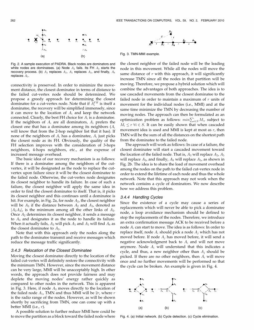
Moving the closest dominatee directly to the location of thefailed cut-vertex will definitely restore the connectivity withthe minimum TMN. However, since the movement distancecan be very large, MMI will be unacceptably high. In otherwords, the approach does not provide fairness and maydeplete the moving nodes’ energy rather quickly ascompared to other nodes in the network. This is apparentin Fig. 3. Here, if node A3 moves directly to the location ofthe failed node A1, TMN and thus MMI will be 2r, where ris the radio range of the nodes. However, as will be shownshortly by sacrificing from TMN, one can come up with abetter MMI (i.e., r).
A possible solution to further reduce MMI here could beto move the partition as a block toward the failed node where
the closest neighbor of the failed node will be the leading
node in this movement. While all the nodes will move the
same distance of r with this approach, it will significantly
increase TMN since all the nodes in that partition will be
moving. Therefore, we propose a hybrid solution which will
combine the advantages of both approaches. The idea is to
use cascaded movements from the closest dominatee to the
failed node in order to maintain a maximum of r units of
movement for the individual nodes (i.e., MMI) and at the
same time minimize the TMN by decreasing the number of
moving nodes. The approach can then be formulated as an
optimization problem as follows: minP
i2S Mi, subject to
Mi � r 8i 2 S. It can be easily shown that when cascaded
movement idea is used and MMI is kept at most as r, then
TMN will be the sum of all the distances on the shortest path
from the dominatee to the failed node.The approach will work as follows: In case of a failure, the
closest dominatee will start a cascaded movement towardthe location of the failed node. That is, A3 will replace A2, A5
will replace A3, and finally, A8 will replace A5, as shown inFig. 2b. The idea is to share the load of movement overheadamong the nodes on the path to the failed cut-vertex node inorder to extend the lifetime of each node and thus the wholenetwork. Note that this approach may not work when thenetwork contains a cycle of dominators. We now describehow we address this problem.
3.4.4 Handling Cycles
Since the existence of a cycle may cause a series ofreplacements which will never be able to pick a dominateenode, a loop avoidance mechanism should be defined tostop the replacements of the nodes. Therefore, we introducean extra confirmation message ACK to be received before anode Ai can start to move. The idea is as follows: In order toreplace itself, node Ai should pick a node Aj which has notmoved before. If node Aj has moved before, it will send anegative acknowledgment back to Ai and will not moveanymore. Node Ai will understand that this indicates acycle, and thus, a new neighbor other than Aj should bepicked. If there are no other neighbors, then Ai will moveonce and no further movements will be performed so thatthe cycle can be broken. An example is given in Fig. 4.
262 IEEE TRANSACTIONS ON COMPUTERS, VOL. 59, NO. 2, FEBRUARY 2010
Fig. 2. A sample execution of PADRA. Black nodes are dominators andwhite nodes are dominatees. (a) Node A2 fails. Its FH A3 starts therecovery process. (b) A3 replaces A2, A5 replaces A3, and finally, A8
replaces A5.
Fig. 3. TMN-MMI example.
Fig. 4. (a) Initial network. (b) Cycle detection. (c) Cycle elimination.

3.4.5 Detailed Pseudocode
Due to space constraints, we skip the detailed pseudocodefor designating a FH for a node. The algorithm, namedRecovery as shown in Algorithm 1, is run on the FH of thefailed node i. Move(.) function is called when a node ismoving. In that case, the node first informs its predecessornode to replace itself by sending a “LEAVING” message. Itthen moves to the new location and broadcasts an“ARRIVED” message and updates its CDS accordingly.
Algorithm 1. Recovery(FH, i)
// FH ! failure handler designated upfront
for node i
1 if i fails then
2 if isDominateeðFHÞ ¼ true then
3 MoveðFH; i; nullÞ4 else if isDominatorðFHÞ ¼ true then
// Check if FH has a dominatee neighbors
5 if 9j 2 NðFHÞ ^ isDominateeðjÞ ¼ True then
6 MoveðFH; i; jÞ7 else
8 j ClosestNeighborðFHÞ9 MoveðFH; i; jÞ
// Since FH replaced i, j needs to
replace FH
10 end
3.5 Handling Partitioning: Dynamic Programming
The algorithm that we proposed in Section 3.4 is a greedyCDS-based approach. However, in some circumstances,selecting the closest neighbor dominator may not alwaysprovide the optimal solution in terms of TMN. We arguethat we can find the optimal solution at the expense ofincreased message complexity by using a dynamic pro-gramming approach. The idea is to find the least cost pathto the closest dominatee. Therefore, the FH node starts asearch process among the subtrees of its neighbors in orderto find the closest dominatee. Basically, each subtree returnsits cost of reaching a dominatee to the FH. The FH picks theleast cost dominatee among these options rather than usinga greedy approach, as shown in Algorithm 2. With thisapproach, node i in line 8 of Procedure Recovery(FH, i) inAlgorithm 1 will start a recursive call to all of its neighborsasking for a dominatee as seen in Algorithm 2. Each callercan compute the minimum cost of finding a dominateenode by using the formula given in (1).
Algorithm 2. ClosestDominatee(FH)1 if i is a dominatee then
2 cost 0
3 else if i is a dominator and jEij > 0 then
4 cost minðDistðDominateeðiÞÞÞ5 else
6 Broadcastði; 0CLOSEST DOMINATEE0Þ7 forall j 2 NðiÞ do
8 cost Distði; jÞ þ ClosestDominateeðjÞ9 Receiveði;0DOMINATEE FOUND0Þ
10 putintoMapði; cost;mapÞ11 end
12 minindex getIndexOfMinCostðmapÞ13 return minindex
ci ¼minj2Eifdijg; Ei 6¼ 0;minj2Di
fdij þ cjg; Ei ¼ 0;
�ð1Þ
where i is a dominator, ci is the total travel distance toreplace i, dij is the euclidean distance between i and j, andEi and Di are the number of dominatees and dominatorsof node i, respectively. The FH will start replacing the nodewith the ID of minindex which will be done recursivelyuntil the dominatee is replaced. With dynamic program-ming, there is no risk of getting cycles, and thus, weeliminate the “ACK” message. We will refer this approachas PADRA-DP hereafter to differentiate it from PADRAusing greedy approach.
4 ALGORITHM ANALYSIS
4.1 Travel Distance Analysis
When the TMN is considered, there are three factors whichaffect the performance with respect to different algorithms,as shown in Table 1. These are number of false alarms incut-vertex determination, selection of FH, and determina-tion of the closest dominatee.
As summarized in Table 1, the variants of PADRA willnot provide the optimal (i.e., the minimum) TMN. WhilePADRA+ ensures zero false alarms in determining the cut-vertices, it utilizes greedy approaches in the selection of FHwhich is also true for PADRA and PADRA-DP as well.Basically, we only consider 2-hop neighbor information inthe selection of the FH. If a dominatee does not exist within2-hop neighborhood, then the selection is based on a greedyapproach which basically designates the closest neighbor asthe FH. Optimal solution would consider all the neighbors,and then, pick the one that will trigger the less number ofmovements. Similarly, the determination of the closestdominatee is based on a greedy approach in PADRA andPADRA+. While PADRA-DP utilizes a dynamic program-ming approach, it suffers from false alarms and poorFH selection. Obviously, the optimal solution will outper-form all the approaches in terms of TMN in average but itwould require either a centralized approach or excessiveand unnecessary flooding of the whole network by all thenodes in advance. Nonetheless, we show that in the worstcase, the TMN for the optimal solution is also the same asthe variants of PADRA.
Theorem 1. The worst case TMN for PADRA, PADRA+,PADRA-DP, and Optimal solution is O(nr).
Proof. The worst case topology for TMN is depicted in Fig. 5for PADRA, PADRA+, and PADRA-DP. In this topology,assuming that A4 fails, in the worst case, the FH would beA5 which triggers movement till An is hit. Note that A3
AKKAYA ET AL.: DISTRIBUTED RECOVERY FROM NETWORK PARTITIONING IN MOVABLE SENSOR/ACTOR NETWORKS VIA CONTROLLED... 263
TABLE 1Factors Affecting the TMN Performance

cannot be picked since it will not trigger the worst number
of movements. Thus, TMN for PADRA, PADRA+, and
PADRA-DP is given byPn�4
i¼1 r ¼ ðn� 4Þr ¼ OðnrÞ, as-
suming that the distance between the nodes is equal to the
maximum value of the transmission range r.
For the optimal solution, however, A3 will be picked
as the FH, and thus, TMNOptimal ¼ 3r. The worst case for
the optimal solution would be the case where the node in
the middle of the line topology in Fig. 5 (i.e., Aj such that
j ¼ nþ12 ) fails. In this case, whether the FH is selected as
Aj�1 or Ajþ1, the TMNOptimal will bePðnþ1
2 �1Þi¼1 r ¼ ðn�1
2 Þrwhich is also O(nr). tu
4.2 Message Complexity Analysis
Before calculating the message complexity based on the
worst case topology, we provide the type and number of
messages sent, in general, in Table 2. For each approach, we
summarize how many messages are needed at each step of
the algorithm. These steps are as follows:
1. CDS determination. Each node sends four messages inorder to determine whether it is a dominator or adominatee [20].
2. Cut-vertex Determination. Each node determineswhether it is a cut-vertex or not. For dominatees,there is no cost in terms of messaging. This is also truefor dominators in PADRA or PADRA-DP since eachnode just checks its 2-hop neighborhood table set instep 1 and decides whether it should be a cut-vertexor not. In PADRA+, a DFS should be performed inone of the subtrees leaded by the closest neighbor ofthe node. Given H denotes the number of neighbors,T the number of nodes in the subtree, and k thenumber of hops to the closest dominatee, we cancalculate the message complexity as follows: Thenode sends one broadcast message and receivesH replies from its neighbors. T messages are neededto reach the nodes within the subtree leaded by theclosest neighbor. Thus, totally, ðT þH þ 1Þmessageswill be needed. Finally, when a failure happens, 2k(i.e., “LEAVING” and “ARRIVED” messages perhop) messages are sent to restore the connectivity.
3. FH Determination. In each approach, every cut-vertexdetermines an FH for itself. This is again done byaccessing the 2-hop neighbor table. Once the nodedecides, it informs the FH with a message. Ob-viously, a node which is not a cut-vertex does notdesignate an FH, and thus, no messages are sent.
4. Finding the closest dominatee and replacement. TheFH node determines the closest dominatee by agreedy search. Each time the closest neighbor isreplaced until a dominatee is found. This requiresthree messages (including the ACKs) at each node,and thus, totally 3k messages are needed, where k is
the number of hops to the closest dominatee. In caseof PADRA-DP, dynamic programming is used, andthus, an additional 2T messages are needed tosearch the subtree and get the optimal result. Inaddition, since there will be no cycles, two messageswill be enough for replacements. Therefore, a total of2T þ 2k messages will be needed. The overallmessage types and counts are provided in Table 2.
The worst case behavior of PADRA, PADRA+, andPADRA-DP can again be observed when the topology is aline, as shown in Fig. 4. Based on such topology, weintroduce the following theorems:
Theorem 2. Worst-case message complexity of PADRA is O(n).
Proof. Let us assume that A3 failed and A4 was the failurehandling node. Then, A4 will start a replacement processuntil An is hit. This means that a total of n� 3 nodes willbe replaced. At each replacement a request and anACK messages were used. Thus, 2ðn� 3Þ messages willbe sent to restore the connectivity. Adding 4n messagesfor CDS and n for closest node designation, the totalnumber of messages in the worst case for PADRA will be7n� 6 which is O(n). tu
Theorem 3. Worst-case message complexity of PADRA-DP isO(n).
Proof. Let us again assume that A3 failed and A4 withrespect to Fig. 5 was the failure handling node. Then, A4
will start a replacement process based on dynamicprogramming to determine the closest dominate. Thismeans that a total of ðn� 3Þmessages will be transmittedand come back, totaling 2n� 6 messages. Once theclosest dominatee and the path to that dominatee areavailable at node A4, it will start a replacement byfollowing the next hop on the path to the closestdominatee. Thus, ðn� 3Þ messages will be sent to restorethe connectivity. Adding 4n messages for CDS and n forPFH designation, the total number of messages in theworst case for PADRA-DP will be 8n� 9 which is O(n).tu
Theorem 4. Worst-case message complexity of PADRA+ isO(n2).
Proof. In PADRA+, a DFS is performed for each cut-vertex,from A3 to An�2, again with respect to Fig. 5. Thus, thenumber of nodes performing DFS will be ðn� 4Þ. For A3,this will cost traversing each node until An in the worstcase when DFS is performed throughA4. Thus, given T ¼n� 3 and H ¼ 1, a total of ðn� 1Þ messages will be sent.The total number of messages for An�2 is n� 1 as well if
264 IEEE TRANSACTIONS ON COMPUTERS, VOL. 59, NO. 2, FEBRUARY 2010
Fig. 5. Worst-case topology for TMN with dominatees at two ends.
TABLE 2Type and Count of Messages Used

we assume that An�3 will start the DFS. As a result, onlytwo nodes will introduce a total of ðn� 1Þ messages, therest will introduce even smaller number of messages. Forinstance, for A4 and A5, the total messaging costs are ðn�2Þ and ðn� 3Þ, respectively. Therefore, the total messa-ging cost will be ðn� 1Þ þ ðn� 2Þ þ � � � þ ðn� ðn�4
2 ÞÞ þ. . . þ ðn� 2Þ þ ðn� 1Þ. This can be expressed as
2Xðn�4Þ
2
i¼1
ðn� iÞ
24
35;
which reduces to ðð3n2�10n�8Þ
4 Þ and the worst case messagecomplexity of Oðn2). tu
Theorem 5. The total number of messages sent in PADRA+ inthe worst case is less than that of the optimal solution.
Proof. In the optimal cascading case, each needs to know
the whole topology. This will require ðn� 1Þ broadcasts
for A1 and An and ðn� 2Þ broadcasts for the rest, totaling
ðn2 � 2nþ 2Þ with two more messages for replacement.
Obviously, ðn2 � 2nþ 2Þ > ðð3n2�10n�8Þ
4 Þ. Thus, PADRA+
has less messaging cost when compared to the optimal
solution. tu
4.3 Time Complexity Analysis
The period of time it takes to restore the connectivity is alsoa key concern since the network will be disconnectedduring this transition time. The main factor here is the timeit takes for a node to reach its final destination whichdepends on the speed of the node. Therefore, MMI willdirectly affect the time for the network to be recovered.Messaging is also a concern but it will bring minimaloverhead when compared to movement.
Theorem 6. The worst-case time complexity of PADRA,PADRA+, and PADRA-DP is Oðrsþ ðpþ tÞnÞ, where s isthe speed of nodes, p propagation delay dor distance r, and tthe transmission delay.
Proof. Assuming a failure occurred, the FH will send amessage to its closest neighbor, get an ACK, and move toreplace the failed node. Similarly, the node receiving thismessage will do the same thing and move to replace theFH. Therefore, the replacements can be done in parallel.That is, while the first node is moving its predecessor willalso start moving, etc. In this way, as soon as the messageis received by a dominatee, it will take it at most rs time toreplace its successor node, where r is the distancerepresented by the transmission range and s is the speedof the node. The time it takes the message to reach thedominatee can be computed as follows: At each node,three messages are sent. Thus, total time will be 3ðpþ tÞ,where p is the propagation delay and t is the transmis-sion delay. Since there can be at most ðn� 4Þ hops, thetotal time will be 3ðn� 4Þðpþ tÞ. Adding the movementtime, the total will be which is Oðrsþ ðpþ tÞnÞ.
For PADRA-DP, the messaging delay is higher. First theclosest dominatee is found in 2ðn� 4Þðpþ tÞ (i.e., 2T ) time.Then, the replacements are done in time since no ACK isneeded. Total will be which is again Oðrsþ ðpþ tÞnÞ. tu
5 MULTIPLE SIMULTANEOUS NODE FAILURES
PADRA assumes that only one node fails at a time and noother nodes fail until the connectivity is restored due to aparticular cut-vertex failure. However, there may besituations (i.e., in case of flooding, thunderstorms, etc.)where two or more cut-vertices may fail around the similartimes which will require the execution of PADRA simulta-neously by the FHs of the failed nodes. Such simultaneousexecution may fail to restore the connectivity since thenodes do not have the up-to-date state information of theirneighbors and race conditions may occur. In other words,multiple FHs may compete to access the same set of nodesto replace their failed nodes. As a result of such competi-tion, even if a First-Come-First-Served mechanism isapplied, some of the nodes can get stuck and have to waitfor the others to finish the replacements. Even worse, somedeadlock situations may occur when two nodes wait foreach other. This requires extra messaging and may delaythe recovery process. Therefore, a mechanism which willhandle race conditions, update the network state appro-priately, and provide parallel replacements is needed. Inthis section, we will explain in details how PADRA shouldbe modified to handle simultaneous failures of multiplenodes. We name the approach as Multiple PADRA(MPADRA) thereafter.
5.1 MPADRA Overview
Depending on the location of the failures of the nodes, therecovery process may introduce race conditions where thesame node, say Ai, may be requested to replace multiplenodes, say Aj and Ak. In that case, a mutual exclusionmechanism is needed to make sure that only one of thenodes among Aj and Ak can use Ai for replacing itself.Otherwise, Ai will not know which one to replace. Inaddition, even if it replaces one, the other will not be able toproceed in the cascaded relocation process, and thus, theconnectivity will not be restored despite a number ofreplacements have already been made. One possiblesolution here is to wait until one of the failures is fixedand continue from where the recovery process stopped.However, this not only requires an alerting framework toinform the node about the end of the recovery process, butalso cause unnecessary delay in restoring the connectivity.Such delay may not be tolerated in mission critical wirelesssensor/actor networks.
We present a solution which is based on two phases: Inthe first phase, an FH will reserve the nodes to be replacedbefore replacements are made as opposed to PADRA. Thegoal of this reservation is similar to RSVP protocol [21]where the nodes on a path are reserved for a certainconnection. In our case, we strive to lock all the nodes onthe path through the closest dominatee so that no otherrecovery processes can use those nodes for replacement.Nevertheless, during this reservation, phase race conditionsoccur if a node receives a reservation message from twonodes at similar times. In that case, the node which sent themessage first will have the priority and be able to lock thatnode for itself. The other node will back off and look for analternative dominatee. Note here that such reservation maycause other FH to reserve a dominatee from a longer path.
AKKAYA ET AL.: DISTRIBUTED RECOVERY FROM NETWORK PARTITIONING IN MOVABLE SENSOR/ACTOR NETWORKS VIA CONTROLLED... 265

As our approach is not centralized, with local informationavailable at the nodes, this is inevitable.
However, depending on the topology, such a dominateemay not be found. In that case, the only way to restore theconnectivity is to use a secondary (the second closest node)FH (SFH) which will look for another dominatee on anotherpath. Basically, the primary FH (PFH) will time out andSFH will take over the recovery process. Once the nodes tobe replaced are reserved for FHs, in the second phase, theywill apply the cascaded motion as in PADRA, update theCDS, and unlock the nodes that have been locked forreplacement purposes. We now explain how MPADRA canhandle possible multiple failure scenarios.
5.2 MPADRA Details
Let us assume two nodes, namely, u and v which fail atapproximately the same time. We introduce the followingnotation in Table 3 for representing the PFH, SFH,Closest Dominatees, and the path to that closestdominatee for such nodes. MPADRA will work in twophases as mentioned above:
Phase I: Path reservation. As soon as a PFH uPFH , whichis a 1-hop neighbor of the failed node u detects that u, hasfailed, it starts the first phase of the recovery process bysending a “RESERVE” message to its closest dominatee. Ifthere is no such dominate, it sends it to its closestdominator. A node receiving a “RESERVE” message willeither accept the request (i.e., not respond) or send a NACKmessage (i.e., negative acknowledgment) depending on itsstate. If the node has not already been reserved by anothernode (i.e., is unlocked), it will not send any messages butchange its state to locked (See Fig. 6a). Otherwise, it willsend a NACK message back to the originator of “RESERVE”message. Once a node is locked, it applies the sameprocedure and tries to lock a dominatee if any. This processcontinues until a dominatee has been locked. In themeantime, the other PFH vPFH also tries to lock a dominateein the same way. During this first phase, depending on thelocation of the failed nodes u and v, the following cases arepossible: 1) The paths to the closest dominatees of uPFH andvPFH do not share any common links (i.e., P ðuPFH; uCDÞ andP ðvPFH; vCDÞ as seen in Fig. 6b.
This is the simplest case which does not require any special
treatment. Basically, both uPFH and vPFH will independently
and simultaneously execute Phase 1 of MPADRA and be able
to reserve uCD and vCD (and any nodes on the paths to uPFH
and vPFH). 2) P ðuPFH; uCDÞ and P ðvPFH; vCDÞ share some
common links/nodes, as seen in Fig. 7. In this case, there are
race conditions where uPFH and vPFH compete to reserve a
node. For instance, in Fig. 7a, while uPFH is trying to reserve
uCD, vPFH is also trying to reserve uPFH and vCD (uCD).
Therefore, whichever makes the reservation and locks the
nodes first will be able to recover its failed node. If u fails first,
uPFH and uCD are locked. In the meantime, if vPFH requests
uPFH , it will not be able to do so. Thus, it will back off and try
the second closest neighbor y and can reach and reserve
dominatee x. However, if such an option is not possible, then
vPFH will get stuck and will not be able to reserve a
dominatee. This indicates that the PFH will fail to restore
the connectivity, and thus, SFH should be involved to start
the recovery process. In this case, the nodes which are locked
(if any) should be unlocked starting backward from the node
which got stuck. To do that the final node which got stuck
starts sending a “RELEASE” message back to the node that
tried to reserve it before. In that case, any node receiving a
“RELEASE” message in locked state will go back to unlocked
state, as shown in Fig. 6a.Given that there are cases where PFH fails to restore the
connectivity, we define a time-out value for SFHs. Forinstance, in Fig. 7a, node vSFH , which is the SFH of v, willwait for time � to see the vPFH replacing v. If suchreplacement is not done within � , then vSFH will assumethat vPFH failed to restore the connectivity, and thus, itstarts a new recovery process for restoring the connectivitydue to failure of v. Note that this also applies to failure of u.If v fails first, and thus, vPFH locks nodes uPFH and uCD,then uPFH will not be able to reserve any node for handlingthe failure of u. In that case, uCD times out and starts a newrecovery process.
Selection of the value of � can be based on an estimateof the time it takes a PFH node to replace the failed node.The time to replace the failed node will be r
s . Consideringthe round-trip time required for reservation of the path,in the worst case, it will be ðn� 2Þðpþ tÞ. Then, � shouldbe set at least to the sum of travel time and the round-triptime: � > ðrsþ 2ðpþ tÞðn� 2ÞÞ.
Note that Figs. 7b, 7c, and 7d illustrate special cases of 2where the PFHs are not able to restore the connectivity. InFig. 7b, P ðuPFH; uCDÞ passes through v and P ðvPFH; vCDÞ
266 IEEE TRANSACTIONS ON COMPUTERS, VOL. 59, NO. 2, FEBRUARY 2010
TABLE 3Notation for the Nodes Involved in MPADRA
Fig. 6. (a) The states of a node in MPADRA. (b) Case 1: u and v executein parallel without facing any race condition.
Fig. 7. Case 2: Situations where paths for recovery have commonnodes/links.

passes through u. This case is a situation where uPFH willfail to reserve vPFH and vice versa. Therefore, both SFHsuSFH and vSFH need to get involved and recover the failednode u and v, respectively. Similarly, in Fig. 7c, PFHs for uand v are same (i.e., uPFH ¼ vPFH), and thus, cannot reserveany path for both u and v. The failures are handled by theSFHs of u and v. In some cases, both the node and itscorresponding PFH can fail at the same time, as shown inFig. 7d. In this case, again the SFHs will time out and handlethe failures.
Finally, we would like to note that SFHs may get stuck inreserving a path when the number of failed nodes is morethan two. For such cases, we adapt and use the idea ofexponential back-off mechanism of traditional Ethernetalgorithm. That is, an SFH will need to back off and retryreserving the nodes on the path after a certain amount oftime with the hope that some of the failures have alreadybeen fixed. If it still cannot reserve the path in the secondtrial, its timer will be doubled. In this way, eventually, allthe partitions will be recovered.
Phase II: Replacements. Once the paths are reservedsuccessfully (i.e., a dominatee is locked) for each PFH (orSFH), now the replacements can be done safely withoutrunning into race conditions. The replacements are donestarting from the dominatee node. However, some paralle-lism can be exploited as each node knows where to go.Basically, the dominate node broadcasts a “LEAVING”message and starts moving toward its new location. Assoon as such “LEAVING” message is received at the nodeto be replaced, it also broadcasts a “LEAVING” messageand starts moving. As a result, every node receiving the“LEAVING” message on the path starts moving to theirnew locations. As soon as a node reaches its new location, itbroadcasts an “ARRIVED” message to its neighbors forupdating the network states as in PADRA. The connectivityis restored when PFH replaces the failed node.
Detailed pseudocode. The pseudocode for MPADRA isgiven in Algorithm 3. This is a generic code which will workat any node during the execution of MPADRA. Algorithm 3will be invoked at a PFH if it detects a failure or at a nodewhich receives a “RESERVE/NACK/LEAVING” messageor at an SFH which has timed out after the failure of itsinvoker. i is the node that runs this procedure. Initially,invoker is null since it is dead and i ¼ PFH=SFH. We skipthe details of the algorithm due to space constraints.
Algorithm 3. Recovery(invoker, i)
1 if state ¼¼ unlocked then state locked
2 if isDominateeðiÞ ¼¼ true then Moveði; invokerÞ3 else if isDominatorðiÞ ¼¼ true then
// Check if i has a dominatee among its
neighbors
4 if 9j 2 NðiÞ ^ isDominateeðjÞ ¼¼ True then
5 Unicastði; j; 0RESERVE0Þ// send message to j. j runs Recovery
(i, j)
6 else if 9j 2 NðiÞ ^ isDominatorðjÞ ¼¼ True then
7 Unicastði; j; 0RESERVE0Þ// send message to j. j runs Recovery
(i, j)
8 else if 8j 2 NðiÞjj ¼¼ ðFAILEDorLOCKEDÞthen
9 // i is stuck.
10 if SFHðiÞ ¼¼ True then Backoff and double
timer
11 else Unicastði; invoker; 0RELEASE0Þ12 else if state ¼¼ locked and 0RESERVE0 msg is
received then
13 Unicastði; invoker; 0NACK0Þ // already
reserved
14 else if state ¼¼ locked and 0LEAV ING0 msg isreceived then
15 Moveði; invokerÞ16 else if state ¼¼ locked and 0NACK0 msg is received
then = � try other dominatees and
dominators, if there is no available
neighbor �=17 state unlocked // reservation failed
18 Unicastði; invoker; 0RELEASE0Þ
5.3 MPADRA Analysis
Theorem 7. The TMN in the worst case is rðn� 4Þ inMPADRA.
Proof. Assuming a line topology as in Fig. 5, in the worst
case, two nodes in the middle fail and their PFHs are
in the opposite directions. Then, each will introduce a
TMN of rððn�2Þ2 � 1Þ, totaling rðn� 4Þ for restoring
connectivity. tuTheorem 8. Worst-case message complexity of MPADRA is
O(n).
Proof. Assuming the line topology in Fig. 7d, the worst case
will be two independent recovery processes running in
parallel. One of the SFHs starting the reservation phase
will need to send one “RESERVE” message. If ðn�2Þ2 nodes
are involved, a total of ðn�2Þ2 messages will be needed to
reserve a path assuming no race conditions. Replace-
ments will require ðn� 2Þ (i.e., “LEAVING” and “AR-
RIVED” messages for each moving node) messages. And
finally, ðn�2Þ2 messages to release the locks (i.e., “RE-
LEASE”) will be required. Total will be 2ðn� 2Þ for one
SFH. For two SFHs, the number of messages required is
4n� 8. If we add the cost of CDS ð4nÞ and PFH ðnÞ and
SFH selection ðnÞ, the total will add up to 10n� 8 which
is O(n). tuTheorem 9. The worst case time complexity of MPADRA is
Oðrsþ ðpþ tÞnÞ.Proof. Assuming one of the PFHs fails to restore con-
nectivity, the corresponding SFH will need to wait for� ¼ ðrsþ 2ðn� 2Þðpþ tÞÞ before it times out as explainedbefore. Once this happens, it needs to reserve the pathwhich requires ðn� 2Þðpþ tÞ time, and then, startreplacements which requires another ðn� 2Þðpþ tÞ timeto inform SFH to replace the failed node. The time ittakes to reach the new location will be at most r
s . Thus,total time needed will be at most 2r
s þ 4ðn� 2Þðpþ tÞ,which is Oðrsþ ðpþ tÞnÞ. tu
AKKAYA ET AL.: DISTRIBUTED RECOVERY FROM NETWORK PARTITIONING IN MOVABLE SENSOR/ACTOR NETWORKS VIA CONTROLLED... 267

6 EXPERIMENTAL EVALUATION
6.1 Experiment Setup and Performance Metrics
In the experiments, we considered a forest monitoringapplication where movable robots with fire extinguishersare deployed within sensors. Each robot is collecting datafrom sensors and needs to be in communication with otherrobots. We created connected networks of these robotsconsisting of varying number of nodes randomly placed inan area of interest of size 700 m� 700 m. Each simulation isrun for 30 different network topologies and the averageperformance is reported. The dominatees and dominatorsare determined through running the distributed algorithmin [20]. For each topology, one of the cut-vertices is pickedto be failed in such a way that there will be no dominateesamong the neighbors of the cut-vertex. We used TMN, totalnumber of messages, # of false alarms for cut-vertexdetection as the performance metrics. We comparedPADRA, PADRA-DP, and PADRA+ with DARA [16] andthe optimal cascaded movement solution which providesthe least travel distance.
6.2 Performance Evaluation of PADRA
False alarms for cut-vertices. We first checked the effective-ness of our cut-vertex detection algorithm. Mainly, welooked at the false alarm rate when PADRA is used. Inorder to perform this experiment, we created randomtopologies and for each topology, we counted the numberof cut-vertices found by PADRA and PADRA+. The resultsin Fig. 8a show that PADRA can detect all the nodes whichare really cut-vertices, but it also falsely identifies morenodes as cut-vertices although they are not. However, suchfalse ratio is not very high, particularly when the nodetransmission range and the number of nodes are smaller. Inother words, if degree of connectivity is high and thenetwork contains cycles, then the number of false alarms willbe higher for PADRA. For instance, in Fig. 8a, for 60 nodesand 50 m transmission range, the false alarm ratio is almost
negligible (i.e., 1.5 percent). However, the false alarm ratio isaround 15 percent when the transmission range is 200 m.
Based on these observations, we can conclude that in ourtarget application of forest monitoring, PADRA+ can beemployed as the transmission range of the robots will behigher when compared to normal sensors. In addition, themessaging cost/delay is not of concern, since the nodes areassumed to be more powerful and the determination of cut-vertices is done upfront. PADRA, on the other hand, can beused with sensor networks where the transmission range issmaller and messaging energy cost can be significant.
TMN. We evaluated the movement performance of ourapproach by varying the number of nodes (20-100). Fig. 8bshows that different versions of PADRA performed veryclose to the optimal cascading while significantly out-performing DARA. Our approach maintains similar TMNseven when the network size grows, as seen in Fig. 8b,indicating its scalability. The reason for such goodscalability is due to termination of the replacements whena dominatee is hit. Since the dominatees can be anywherein the network (i.e., not just the leaf nodes), there is a highprobability of reaching it earlier than a leaf node and thisis independent of the network size. Note that this is notthe case in DARA and needs to look for a leaf node tostop; making the performance even worse when thenetwork size grows. Optimal cascading performs slightlybetter than PADRA and PADRA+ as it determines theshortest path to the closest dominatee each time. This isalso the case with PADRA-DP since it does not employ agreedy approach for determining the closest dominatee.However, we note that the performance of PADRA-DP iscomparable to PADRA+. This can attributed to the failednode. If the node is identified as cut-vertex in bothapproaches, then PADRA-DP will reduce the travel timecompared to PADRA+ as a result of the usage of greedyand dynamic programming approaches. However, if the
268 IEEE TRANSACTIONS ON COMPUTERS, VOL. 59, NO. 2, FEBRUARY 2010
Fig. 8. (a) Percent of nodes which are falsely identified as cut-vertices in PADRA. (b) TMN with varying number of nodes, r ¼ 100 m. (c) TMN with
varying node transmission range. # of nodes is 40. (d) TMN with varying node transmission range. # of nodes is 40. (e) Total number of messages
with varying number of nodes. (f) Total movement distance of the nodes in MPADRA, r ¼ 100 m. (g) Total movement distance of the nodes with
varying radio range in MPADRA. # of nodes is 60. (h) Total coverage change in MPADRA.

failed node is falsely identified as a cut-vertex (i.e., falsealarm) in PADRA-DP, then PADRA+ will not replace anynodes, and thus, will be better in terms of travel distance.We also conducted a similar experiment by varying thetransmission range (50-200 m), as seen in Fig. 8c. Similarly,PADRA outperformed DARA due to the same reason asmentioned above. Note, however, that as the transmissionrange increases, surprisingly the travel distance alsoincreases. PADRA, PADRA+, and PADRA-DP keep thesame rate of increase as the optimal solution, while DARAperforms worse at higher transmission ranges. Oneexplanation for this increase is the increased transmissionrange, and thus, the travel distance from a node toanother. In addition, cut-vertices with higher transmissionranges are rare since the network connectivity is im-proved. Therefore, if there is a cut-vertex, it usuallyconnects blocks that are far apart which eventuallyincreases travel distance. Since the path for DARAreplacements is longer, travel distance gets even worsewith the increased transmission range. Due to the samereason of not getting many cut-vertices as the transmissionrange increases, the false alarms for PADRA-DP will behigher which makes PADRA+ to slightly outperformPADRA-DP. When comparing PADRA with PADRA+,the latter performs better as it minimizes the error inidentifying the cut-vertices. However, PADRA+ minimizesthis ratio by doubling the message cost as we discuss next.As far as PADRA-DP is concerned, although it doesintroduce false alarms in identifying cut-vertices, suchdisadvantage can be compensated through the use ofshortest paths to dominatees.
Total number of messages. We also compared thenumber of messages sent when determining the cut-vertices, designating primary failure handlers, and repla-cing the failed nodes. The simulation results confirmed thatour approach requires significantly less number of mes-sages for the whole failure handling process whencompared to optimal cascading, as seen in Fig. 8d. Evenfor PADRA+, we observed that on the average, it is muchbetter, although it doubled the number of messagescompared to PADRA, as shown in Fig. 8e.
We also observed that the number of messages inPADRA-DP is significantly less than that of PADRA+. Thisresult is also consistent with the Theorems 3 and 4 provedin Section 4.
6.3 Performance Evaluation of MPADRA
We also performed the same experiments in order to assessthe performance of MPADRA. This time, two random nodesare selected to fail simultaneously. These nodes are pickedamong the cut-vertices and PADRA is used to determinethese cut-vertices. Note that there may be some cases wheresimultaneous failure of two noncut-vertices may also causepartitioning in the network. Since we are using PADRA, itassumes all the dominators as cut-vertices, and thus, anypicked pair can be handled. Definitely, if the two failednodes are both dominatees, then no action will be needed asno partitioning will occur. If only one of them is a dominator,then running PADRA will be enough. If there are twodominators, then they will be assumed as cut-vertices andMPADRA will be executed. For the experiments, we picked
every pair of cut-vertices in a topology and tried 30 differenttopologies. We compared the performance to the optimalsolution in terms of TMN. We also assess the messageoverhead and network coverage change during theseexperiments. The coverage range of a node is assumed tobe 50 m.
TMN. We varied both the number of nodes and the radiorange. The results in Figs. 8f and 8g show that MPADRArestores the connectivity of the network successfully forevery pair of failed nodes and maintains the same TMNperformance ratio to the optimal solution even if thenetwork scales. As expected, the movement distance withoptimal solution is slightly better. However, optimalsolution is a centralized approach and requires lots ofinformation exchange as will be explained later. We observethat distributed solution to fix double failures costs more ascompared with single node failure costs in terms of TMN.This is not surprising since it is like running PADRA twiceto restore connectivity. MPADRA, on the other hand, hasthe ability to perform the handling in parallel. There are twomore observations from the graphs. First, the TMNdecreases or keeps stable with the increasing number ofnodes and radio range. This is due to having moreconnectivity, and thus, closer nodes to replace the failednodes. Second, with the increasing number of nodes andradio range, the performance gap among MPADRA andOptimal solution starts to decrease since there will be moredominatees to pick when the connectivity is improved. Thisreduces the chance for the failure of path reservation in ourapproach, and thus, the travel distance decreases.
Total messages. We also counted the number ofmessages sent during connectivity restoration in MPADRAin order to verify its consistency with the analyticalcomponent. First, we increased the number of nodes andcounted the messages. The number of messages for eachnode count is shown in Table 4a. These results areconsistent with the message complexity OðnÞ, as provedin Theorem 9. Note that the ratio of number of messages tothe number of nodes keeps linear in the figure, indicating alinear message complexity.
When the radio range is increased with a fixed numberof nodes, the number of messages does not changesignificantly as seen in Table 4b. There is only a minordecrease when the radio range gets larger. This is due tobeing able to find closer nodes for replacement. As a result,the length of the path to send reservation and replacementmessages is decreased which helps to save some messages.
AKKAYA ET AL.: DISTRIBUTED RECOVERY FROM NETWORK PARTITIONING IN MOVABLE SENSOR/ACTOR NETWORKS VIA CONTROLLED... 269
TABLE 4# of Messages in MPADRA for
(a) Node Size and (b) Radio Range

Note that we have not made a comparison to the numberof messages for Optimal solution. In this case, the optimalsolution is only possible through a central server which willknow all the nodes and be able to communicate with thenodes remotely. That is, each PFH will have to commu-nicate with the central server which needs to send amessage to the appropriate nodes about when and where tomove. A distributed solution is not possible even if weassume that each node knows the whole topology (i.e., withO(n2) total message complexity). This is because each nodewould need to flood the network before it starts itsreplacements. However, if the network is partitioned, thismay introduce further partitioning problems as the PFHswill not be able to coordinate. Therefore, the messagecomplexity of the optimal solution is not applicable here.
Total coverage. To assess the effect of movements oncoverage, we recorded the initial and final network cover-age for different number of nodes, as seen in Fig. 8h. Theresults show that the coverage change due to movements isvery small in MPADRA. This is not surprising since thetopology change is very minimal (i.e., only dominateenodes are deleted from the topology).
MPADRA is suitable for our targeted forest monitoringapplication since the actors can only know their localneighborhood. However, in target tracking applicationswhere actors can communicate through an unmannedaerial vehicle (UAV) intermittently, optimal solution canbe computed at the UAV and communicated to theappropriate actors. In addition, we note that the effect oncoverage is negligible with two failures. However, when alot of failures are considered, this may necessitate atopology adjustment in terms of coverage using [14] if theinitial network is more than 1-covered.
7 CONCLUSION AND FUTURE WORK
In this paper, we presented a local, distributed, and move-ment-efficient protocol PADRA to handle the failure of anynode in a connected WSAN. As it is unknown at the time offailure whether such failures would cause a partitioning ornot, we provided a technique based on CDS of the networkwhich can decide whether a node is a cut-vertex or not beforethe failure happens. Basically, if a node finds out that it is acut-vertex, the closest dominatee/neighbor is delegated toperform failure recovery on behalf of that node. The failurerecovery is done by determining the closest dominatee nodeand replacing it with the failed node in a cascaded manner sothat the movement load is shared among the nodes that sit onthe path to the closest dominatee.
We further extended PADRA to handle multiplesimultaneous failures in a distributed manner. The pro-posed approach, MPADRA, first reserves the nodes on thepath to the closest dominatee before the replacements areperformed. This is needed since a node may be requested tomove by both failure handlers, and thus, disconnectionsand race conditions can occur. We maintained a statediagram at each node in order to eliminate race conditions.Once the nodes are reserved for handling a certain failure,the replacements can be done safely.
We analyzed the performance of PADRA and MPADRAboth analytically and experimentally. Simulation resultsconfirmed that PADRA performed very close to the optimal
solution in terms of travel distance while keeping theapproach local, and thus, minimizing the message complex-ity. These results were consistent with the analytical resultsderived. In addition, our approach outperformed anotherapproach DARA in terms of travel distance which requiresthe knowledge of 2-hops for each node. Simulation resultsfor MPADRA confirmed that it can restore connectivity in adistributed manner. While the centralized optimal solutionis performing better in terms of travel distance, themessaging complexity of MPADRA is linear, and thus,does not require access to the whole topology information.
As a future work, we plan to work on heuristics whichwill improve the TMN performance of MPADRA. We alsoplan to look at coverage issues in conjunction withconnectivity when movement of a subset of nodes wouldcause sensing coverage holes in terms of some sensingmodalities. We plan to study a new approach which canhandle both connectivity and coverage at the same time atthe expense of slightly increased movement and messagingcost. Finally, we will be testing the performance of theapproach in a real setup which will be consisting of anetwork of mobile robots. A small prototype networkconsisting of three mobile PDX Robots [22] has already beencreated. We plan to extend this network by adding moresensors to test all the proposed protocols in this paper.
REFERENCES
[1] G.T. Sibley and M.H.A. Rahimi, “Robomote: A Tiny Mobile RobotPlatform for Large-Scale Ad-Hoc Sensor Networks,” Proc. IEEEInt’l Conf. Robotics and Automation, 2002.
[2] M.B. McMickell, B. Goodwine, and L.A. Montestruque, “Micabot:A Robotic Platform for Large-Scale Distributed Robotics,” Proc.IEEE Int’l Conf. Robotics and Automation (ICRA), pp. 1600-1605,2003.
[3] I.F. Akyildiz and I.H. Kasimoglu, “Wireless Sensor and ActorNetworks: Research Challenges,” Elsevier Ad Hoc Network J., vol. 2,pp. 351-367, 2004.
[4] M. Mysorewala, D. Popa, V. Giordano, and F. Lewis, “Deploy-ment Algorithms and In-Door Experimental Vehicles for StudyingMobile Wireless Sensor Networks,” Proc. Sixth Int’l Conf. SoftwareEngineering, Artificial Intelligence, Networking and Parallel/Distrib-uted Computing and First Int’l Workshop Self-Assembling WirelessNetworks (ACIS-SAWN), pp. 290 - 298, June 2006.
[5] M. Younis and K. Akkaya, “Strategies and Techniques for NodePlacement in Wireless Sensor Networks: A Survey,” Elsevier AdHoc Network J., vol. 6, no. 4, pp. 621-655, 2008.
[6] R.C. Shah, S. Roy, S. Jain, and W. Brunette, “Data Mules: Modelinga Three-Tier Architecture for Sparse Sensor Networks,” Proc. IEEEWorkshop Sensor Network Protocols and Applications (SNPA ’03),May 2003.
[7] A. Kansal, A. Somasundara, D. Jea, M. Srivastava, and D. Estrin,“Intelligent Fluid Infrastructure for Embedded Networks,” Proc.MobiSys ’04, June 2004.
[8] E. Lloyd and G. Xue, “Relay Node Placement in Wireless SensorNetworks,” IEEE Trans. Computers, vol. 56, no. 1, pp. 134-138, Jan.2007.
[9] D. Goldenberg, J. Lin, A.S. Morse, B. Rosen, and Y.R. Yang,“Towards Mobility as a Network Control Primitive,” Proc.MobiHoc ’04, 2004.
[10] K. Akkaya and M. Younis, “Coverage and Latency Aware ActorPlacement Mechanisms in Wireless Sensor and Actor Networks,”Int’l J. Sensor Networks, vol. 3, no. 3, pp. 152-164, May 2008.
[11] M. Ma and Y. Yang, “Adaptive Triangular Deployment Algorithmfor Unattended Mobile Sensor Networks,” IEEE Trans. Computers,vol. 56, no. 7, pp. 946-958, July 2007.
[12] K. Akkaya and M. Younis, “Coverage-Aware and Connectivity-Constrained Actor Positioning in Wireless Sensor and ActorNetworks,” Proc. IEEE Int’l Performance, Computing, and Comm.Conf. (IPCCC ’07), Apr. 2007.
270 IEEE TRANSACTIONS ON COMPUTERS, VOL. 59, NO. 2, FEBRUARY 2010

[13] W. Wang, V. Srinivasan, and K. Chu, “Using Mobile Relays toProlong the Lifetime of Wireless Sensor Networks,” Proc.Mobicom, 2005.
[14] J. Wu and S. Yang, “Smart: A Scan-Based Movement AssistedSensor Deployment Method in Wireless Sensor Networks,” Proc.IEEE INFOCOM, Mar. 2005.
[15] G. Wang, G. Cao, T.L. Porta, and W. Zhang, “Sensor Relocation inMobile Sensor Networks,” Proc. INFOCOM, Mar. 2005.
[16] A. Abbasi, K. Akkaya, and M. Younis, “A Distributed Connectiv-ity Restoration Algorithm in Wireless Sensor and Actor Net-works,” Proc. IEEE Conf. Local Computer Networks (LCN ’07), Oct.2007.
[17] P. Basu and J. Redi, “Movement Control Algorithms forRealization of Fault-Tolerant Ad Hoc Robot Networks,” IEEENetworks, vol. 18, no. 4, pp. 36-44, July/Aug. 2004.
[18] K. Akkaya, F. Senel, A. Thimmapuram, and S. Uludag, “Dis-tributed Recovery of Actor Failures in Wireless Sensor and ActorNetworks,” Proc. IEEE Wireless Comm. and Networking Conf.(WCNC), Sept. 2008.
[19] S.D. et al, “Localized Movement Control for Fault Tolerance ofMobile Robot Networks,” Proc. First IFIP Int’l Conf. Wireless Sensorand Actor Networks (WSANs), Sept. 2007.
[20] F. Dai and J. Wu, “An Extended Localized Algorithms forConnected Dominating Set Formation in Ad Hoc WirelessNetworks,” IEEE Trans. Parallel and Distributed Systems, vol. 15,no. 10, pp. 908-920, Oct. 2004.
[21] R. Braden, L. Zhang, S. Berson, S. Herzog, and S. Jamin, “ResourceReSerVation Protocol (RSVP)—Version 1 Functional Specifica-tion,” RFC 2205, Sept. 1997.
[22] “General Purpose Robot, Pioneer dx,” http://www.mobilerobots.com, Nov. 2008.
Kemal Akkaya received the PhD degree incomputer science from the University of Mary-land Baltimore County in 2005. Currently, he isan assistant professor in the Department ofComputer Science at Southern Illinois Univer-sity Carbondale. His research interests includeenergy-aware routing, security and quality ofservice issues in ad hoc wireless, and sensornetworks. He is a member of the IEEE.
Fatih Senel received the MS degree in compu-ter science from Southern Illinois UniversityCarbondale in 2008. He is currently workingtoward the PhD degree at the Department ofComputer Science, University of Maryland Balti-more County. His research interests includeclustering, topology control, and fault-tolerancein wireless sensor/actor networks.
Aravind Thimmapuram received the MS de-gree in computer science from Southern IllinoisUniversity Carbondale in 2007. He is currentlywith Object Technology Solutions, Inc. Hisresearch interests include relocation and faulttolerance in wireless sensor/actor networks.
Suleyman Uludag received the PhD degreefrom DePaul University in 2007. He is anassistant professor at the University of Michi-gan—Flint. His research interests include guar-anteed and stochastic routing in wired, wirelessmesh and sensor networks, topology aggrega-tion, and channel assignment in wireless meshnetworks. He is a member of the IEEE.
. For more information on this or any other computing topic,please visit our Digital Library at www.computer.org/publications/dlib.
AKKAYA ET AL.: DISTRIBUTED RECOVERY FROM NETWORK PARTITIONING IN MOVABLE SENSOR/ACTOR NETWORKS VIA CONTROLLED... 271


