Embed Size (px)
Citation preview
IEEE TRANSACTIONS ON INDUSTRY APPLICATIONS, VOL. 45, NO. 5, SEPTEMBER/OCTOBER 2009 1831
Stator-Interturn-Fault Detection of Doubly FedInduction Generators Using Rotor-Current and
Search-Coil-Voltage Signature AnalysisDhaval Shah, Member, IEEE, Subhasis Nandi, Senior Member, IEEE, and Prabhakar Neti, Senior Member, IEEE
Abstract—A novel technique for detecting stator interturn faultsin a doubly fed induction generator (DFIG) is proposed by an-alyzing its rotor current and search-coil voltage. So far, fault-diagnostic techniques proposed for stator-interturn-fault detectionin DFIGs are based on analysis of stator current or vibrationof generator. Results from these methods are ambiguous becausethey either fail to account for condition when the DFIG is op-erating under imbalanced load or these methods are based onexperimental results alone without any theoretical basis. Ourrecent observations suggested that harmonics induced in the rotorcircuit are very promising in detecting stator interturn faults inDFIGs. Hence, in this paper, an in-depth investigation is conductedto determine the origin of various harmonic components in rotorcurrents and their feasibility to detect stator interturn faultsunambiguously. Detailed analysis is presented, which explains themechanism by which the stator-interturn-fault-related harmonicsare induced in the rotor circuit. The theory is verified with simula-tion and extensive experimental results. To confirm the feasibilityof the proposed technique for detecting stator interturn faults andobtain results on speed sensitivity of fault detection, a prototypeof digital-signal-processor-based fault-diagnostic system has beendeveloped, which is capable of producing very fast trip signal inabout 2 s.
Index Terms—Doubly fed induction generator (DFIG), motor-current signature analysis (MCSA), stator interturn fault.
I. INTRODUCTION
R ESEARCH in the area of fault diagnosis and conditionmonitoring of wind generators has generated keen interest
as the clamor for renewable energy [1]–[5] becomes louder andclearer due to burgeoning oil prices. Wind generators used forhigh-power range (660 kW to 2 MW) are mainly wound-rotorsynchronous generators and doubly fed induction generators
Paper 2008-EMC-055.R1, presented at the 2007 Industry Applications So-ciety Annual Meeting, New Orleans, LA, September 23–27, and approved forpublication in the IEEE TRANSACTIONS ON INDUSTRY APPLICATIONS bythe Electric Machines Committee of the IEEE Industry Applications Society.Manuscript submitted for review September 22, 2008 and released for publica-tion March 25, 2009. First published July 17, 2009; current version publishedSeptember 18, 2009. This work was supported in part by the Natural Sciencesand Engineering Research Council of Canada, in part by the Canada Foundationfor Innovation, and in part by the University of Victoria, Victoria, BC, Canada.
D. Shah is with Xantrex Technology Inc., Burnaby, BC V5A 4B5, Canada(e-mail: [email protected]).
S. Nandi is with the Department of Electrical and Computer Engineering,University of Victoria, Victoria, BC V8W 3P6, Canada (e-mail: [email protected]).
P. Neti is with the Electric Machines and Drives Laboratory, GeneralElectric Global Research Center, Niskayuna, NY 12309-3523 USA (e-mail:[email protected]).
Digital Object Identifier 10.1109/TIA.2009.2027406
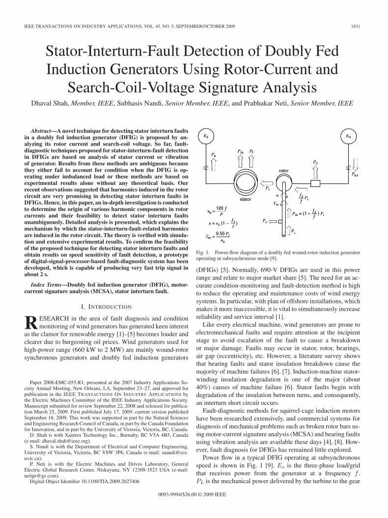
Fig. 1. Power-flow diagram of a doubly fed wound-rotor induction generatoroperating in subsynchronous mode [9].
(DFIGs) [5]. Normally, 690-V DFIGs are used in this powerrange and relate to major market share [5]. The need for an ac-curate condition-monitoring and fault-detection method is highto reduce the operating and maintenance costs of wind energysystems. In particular, with plan of offshore installations, whichmakes it more inaccessible, it is vital to simultaneously increasereliability and service interval [1].
Like every electrical machine, wind generators are prone toelectromechanical faults and require attention at the incipientstage to avoid escalation of the fault to cause a breakdownor major damage. Faults may occur in stator, rotor, bearings,air gap (eccentricity), etc. However, a literature survey showsthat bearing faults and stator insulation breakdown cause themajority of machine failures [6], [7]. Induction-machine stator-winding insulation degradation is one of the major (about40%) causes of machine failure [6]. Stator faults begin withdegradation of the insulation between turns, and consequently,an interturn short circuit occurs.
Fault-diagnostic methods for squirrel-cage induction motorshave been researched extensively, and commercial systems fordiagnosis of mechanical problems such as broken rotor bars us-ing motor-current signature analysis (MCSA) and bearing faultsusing vibration analysis are available these days [4], [8]. How-ever, fault diagnosis for DFIGs has remained little explored.
Power flow in a typical DFIG operating at subsynchronousspeed is shown in Fig. 1 [9]. Es is the three-phase load/gridthat receives power from the generator at a frequency f .PL is the mechanical power delivered by the turbine to the gear
0093-9994/$26.00 © 2009 IEEE
1832 IEEE TRANSACTIONS ON INDUSTRY APPLICATIONS, VOL. 45, NO. 5, SEPTEMBER/OCTOBER 2009
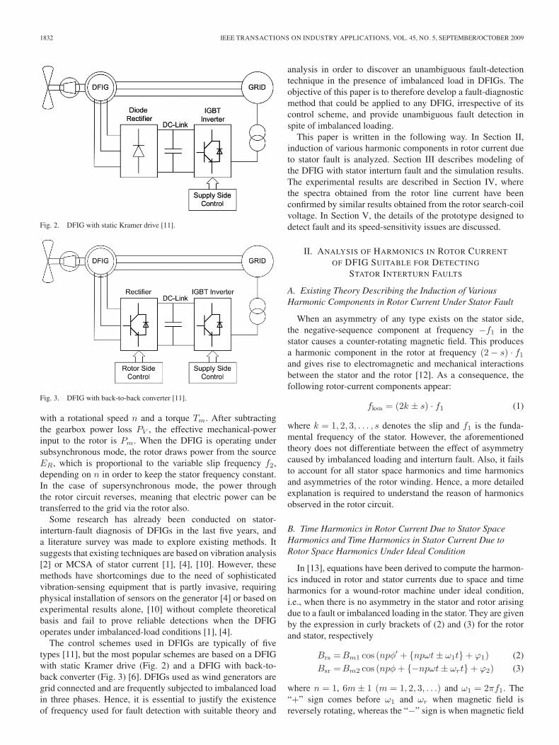
Fig. 2. DFIG with static Kramer drive [11].
Fig. 3. DFIG with back-to-back converter [11].
with a rotational speed n and a torque Tm. After subtractingthe gearbox power loss PV , the effective mechanical-powerinput to the rotor is Pm. When the DFIG is operating undersubsynchronous mode, the rotor draws power from the sourceER, which is proportional to the variable slip frequency f2,depending on n in order to keep the stator frequency constant.In the case of supersynchronous mode, the power throughthe rotor circuit reverses, meaning that electric power can betransferred to the grid via the rotor also.
Some research has already been conducted on stator-interturn-fault diagnosis of DFIGs in the last five years, anda literature survey was made to explore existing methods. Itsuggests that existing techniques are based on vibration analysis[2] or MCSA of stator current [1], [4], [10]. However, thesemethods have shortcomings due to the need of sophisticatedvibration-sensing equipment that is partly invasive, requiringphysical installation of sensors on the generator [4] or based onexperimental results alone, [10] without complete theoreticalbasis and fail to prove reliable detections when the DFIGoperates under imbalanced-load conditions [1], [4].
The control schemes used in DFIGs are typically of fivetypes [11], but the most popular schemes are based on a DFIGwith static Kramer drive (Fig. 2) and a DFIG with back-to-back converter (Fig. 3) [6]. DFIGs used as wind generators aregrid connected and are frequently subjected to imbalanced loadin three phases. Hence, it is essential to justify the existenceof frequency used for fault detection with suitable theory and
analysis in order to discover an unambiguous fault-detectiontechnique in the presence of imbalanced load in DFIGs. Theobjective of this paper is to therefore develop a fault-diagnosticmethod that could be applied to any DFIG, irrespective of itscontrol scheme, and provide unambiguous fault detection inspite of imbalanced loading.
This paper is written in the following way. In Section II,induction of various harmonic components in rotor current dueto stator fault is analyzed. Section III describes modeling ofthe DFIG with stator interturn fault and the simulation results.The experimental results are described in Section IV, wherethe spectra obtained from the rotor line current have beenconfirmed by similar results obtained from the rotor search-coilvoltage. In Section V, the details of the prototype designed todetect fault and its speed-sensitivity issues are discussed.
II. ANALYSIS OF HARMONICS IN ROTOR CURRENT
OF DFIG SUITABLE FOR DETECTING
STATOR INTERTURN FAULTS
A. Existing Theory Describing the Induction of VariousHarmonic Components in Rotor Current Under Stator Fault
When an asymmetry of any type exists on the stator side,the negative-sequence component at frequency −f1 in thestator causes a counter-rotating magnetic field. This producesa harmonic component in the rotor at frequency (2 − s) · f1
and gives rise to electromagnetic and mechanical interactionsbetween the stator and the rotor [12]. As a consequence, thefollowing rotor-current components appear:
fksa = (2k ± s) · f1 (1)
where k = 1, 2, 3, . . . , s denotes the slip and f1 is the funda-mental frequency of the stator. However, the aforementionedtheory does not differentiate between the effect of asymmetrycaused by imbalanced loading and interturn fault. Also, it failsto account for all stator space harmonics and time harmonicsand asymmetries of the rotor winding. Hence, a more detailedexplanation is required to understand the reason of harmonicsobserved in the rotor circuit.
B. Time Harmonics in Rotor Current Due to Stator SpaceHarmonics and Time Harmonics in Stator Current Due toRotor Space Harmonics Under Ideal Condition
In [13], equations have been derived to compute the harmon-ics induced in rotor and stator currents due to space and timeharmonics for a wound-rotor machine under ideal condition,i.e., when there is no asymmetry in the stator and rotor arisingdue to a fault or imbalanced loading in the stator. They are givenby the expression in curly brackets of (2) and (3) for the rotorand stator, respectively
Brs = Bm1 cos (npφ′ + {npωt ± ω1t} + ϕ1) (2)
Bsr = Bm2 cos (npφ + {−npωt ± ωrt} + ϕ2) (3)
where n = 1, 6m ± 1 (m = 1, 2, 3, . . .) and ω1 = 2πf1. The“+” sign comes before ω1 and ωr when magnetic field isreversely rotating, whereas the “−” sign is when magnetic field
SHAH et al.: FAULT DETECTION OF DFIGs USING SIGNATURE ANALYSIS 1833
is forwardly rotating. ω = (1 − s) · ω1/p is the rotor speed inradians per second. ϕ1 and ϕ2 are the arbitrary phase anglesreferred to the rotor and stator, respectively. p is the numberof pole pairs, and “s” is the slip. ωr = 2πfr, where fr is thefundamental frequency of the rotor voltage. φ is the angle instator coordinates, whereas φ′ is the angle in rotor coordinates.Also, φ = φ′ + ωt.
Considering ideal operating conditions, with no imbalancedload on the stator or interturn fault and no rotor asymmetry,f1 = 60 Hz, and s = 0.25, the harmonics induced in rotorcurrent can be calculated using (2)
for n = 5, {5 · (1 − 0.25) · 60 + (60)} = 285 Hz
for n = 7, {7 · (1 − 0.25) · 60 − (60)} = 255 Hz.
Similarly, the harmonics induced in stator current due to timeharmonics in rotor current and rotor space harmonics can becalculated using (3)
for n = 5, {5 · (1 − 0.25) · 60 − (15)} = 210 Hz
for n = 7, {7 · (1 − 0.25) · 60 + (15)} = 330 Hz.
To maintain congruency in the explanation of the theory,the operating condition of the DFIG running at a subsynchro-nous speed of slip = 0.25 and a generating stator voltage atfrequency f1 = 60 Hz is used for further discussion.
C. Time Harmonics in Rotor Current When Stator IsConnected to Imbalanced Load
Load imbalance in stator phases causes negative-sequencecurrents, which causes reverse-rotating magnetic field. Thefrequency of this reverse-rotating magnetic field is the sameas the fundamental frequency but with magnetic field rotatingin the opposite direction. Hence, this reverse-rotating magneticfield at −60 Hz will induce harmonic frequencies in the rotor,which can be calculated using (2)
for n = 1, {1 · (1 − 0.25) · (60) − (−60)} = 105 Hz
for n = 5, {5 · (1 − 0.25) · (60) + (−60)} = 165 Hz
for n = 7, {7 · (1 − 0.25) · (60) − (−60)} = 375 Hz.
Because of load imbalance, the magnetomotive force (MMF)due to triplen space harmonics does not add up to zero; timeharmonics related to triplen space harmonics can also be seen,such as for n = 3. This will be discussed next.
D. Time Harmonics in Rotor Current Due to Statorand Rotor Asymmetry
There always exists an asymmetry to a certain extent inthe stator and rotor windings of an actual induction machine,which gives rise to time harmonics related to triplen spaceharmonics, i.e., for n = 3, 6, 9, . . ., as can be associated withload imbalance and stator-winding loss. Equation (2) suggeststhe following frequencies that can be induced in rotor current,even under balanced load or no interturn fault due to statorasymmetry:
for n = 3, {3 · (1 − 0.25) · 60 − (60)} = 75 Hz.
An asymmetry in the rotor also causes a reverse-rotatingmagnetic field at a frequency of −15 Hz, which induces 30-Hzharmonics in stator current, as given by (3)
for n = 1, {1 · (1 − 0.25) · 60 + (−15)} = 30 Hz.
This 30-Hz harmonics subsequently induces the followingharmonics in the rotor, as given by (2):
for n = 3, {3 · (1 − 0.25) · 60 − (30)} = 105 Hz.
E. Time Harmonics in Rotor Current Due toInterturn Fault in Stator Winding
During an interturn fault, the stator has a shorted loop (canthus be treated as a single-phase winding) carrying currentat supply frequency that generates two counter-rotating MMFwaves [14]. The MMF produced by the asymmetric statorcarrying three-phase balanced voltage can be given as
Fsa = Asa cos(kφ ± ω1t + ϕ1) (4)
where k = 1, 2, 3, . . . corresponds to space-harmonic poles.Considering the specific permeance function (P0), the fluxdensity produced by this MMF, with respect to the stator, canbe given as
Bsa = AsaP0 cos(kφ ± ω1t + ϕ1). (5)
With respect to the rotor, this flux density can be given as
Bra = AsaP0 cos(kφ′ + kωt ± ω1t + ϕ2). (6)
Now, substituting ω = (1 − s) · ω1/p in (6), we can have
Bra = AsaP0 cos(
kφ′ +{
k
p(1 − s) ± 1
}ω1t + ϕ2
). (7)
The frequencies that will be induced in the rotor circuit due toa fault in stator winding when the DFIG is running at s = 0.25,f1 = 60 Hz, p = 2, and different values of k are expressed inTable I using the expression in the curly brackets of (7). As seenfrom Table I, several frequencies can be induced as a result ofthe fault. It has already been shown that the time harmonics instator current and load imbalance also induce harmonics in therotor.
The objective is to therefore find the frequency, which isaffected maximally by fault and minimally by imbalanced loadand other time harmonics. Hence, all these cases will be verifiednext using simulation results to identify such a frequencycomponent.
III. MODELING AND SIMULATION OF DFIGWITH STATOR INTERTURN FAULT
In order to carry out a detailed simulation study, differentmodels of DFIGs have been considered. The winding functionapproach [15] was used to model the DFIG. The machine ismodeled in steady state with constant speed, assuming a motortorque Tm = TL, with TL being the load torque. A resistiveload was connected to the stator, and a three-phase 15-Hz
1834 IEEE TRANSACTIONS ON INDUSTRY APPLICATIONS, VOL. 45, NO. 5, SEPTEMBER/OCTOBER 2009
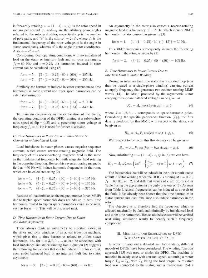
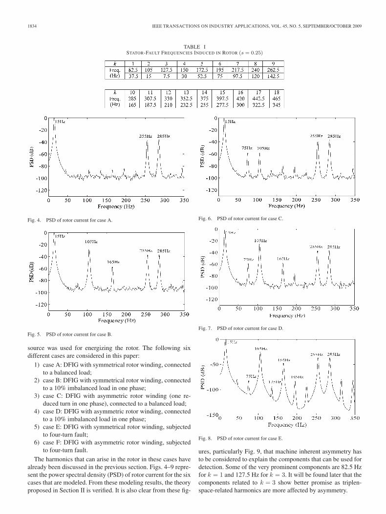
TABLE ISTATOR-FAULT FREQUENCIES INDUCED IN ROTOR (s = 0.25)
Fig. 4. PSD of rotor current for case A.
Fig. 5. PSD of rotor current for case B.
source was used for energizing the rotor. The following sixdifferent cases are considered in this paper:
1) case A: DFIG with symmetrical rotor winding, connectedto a balanced load;
2) case B: DFIG with symmetrical rotor winding, connectedto a 10% imbalanced load in one phase;
3) case C: DFIG with asymmetric rotor winding (one re-duced turn in one phase), connected to a balanced load;
4) case D: DFIG with asymmetric rotor winding, connectedto a 10% imbalanced load in one phase;
5) case E: DFIG with symmetrical rotor winding, subjectedto four-turn fault;
6) case F: DFIG with asymmetric rotor winding, subjectedto four-turn fault.
The harmonics that can arise in the rotor in these cases havealready been discussed in the previous section. Figs. 4–9 repre-sent the power spectral density (PSD) of rotor current for the sixcases that are modeled. From these modeling results, the theoryproposed in Section II is verified. It is also clear from these fig-
Fig. 6. PSD of rotor current for case C.
Fig. 7. PSD of rotor current for case D.
Fig. 8. PSD of rotor current for case E.
ures, particularly Fig. 9, that machine inherent asymmetry hasto be considered to explain the components that can be used fordetection. Some of the very prominent components are 82.5 Hzfor k = 1 and 127.5 Hz for k = 3. It will be found later that thecomponents related to k = 3 show better promise as triplen-space-related harmonics are more affected by asymmetry.
SHAH et al.: FAULT DETECTION OF DFIGs USING SIGNATURE ANALYSIS 1835
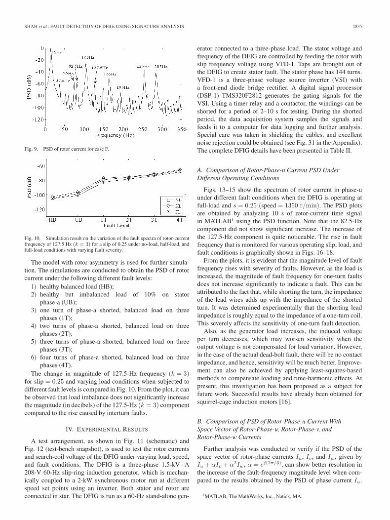
Fig. 9. PSD of rotor current for case F.
Fig. 10. Simulation result on the variation of the fault spectra of rotor-currentfrequency of 127.5 Hz (k = 3) for a slip of 0.25 under no-load, half-load, andfull-load conditions with varying fault severity.
The model with rotor asymmetry is used for further simula-tion. The simulations are conducted to obtain the PSD of rotorcurrent under the following different fault levels:
1) healthy balanced load (HB);2) healthy but imbalanced load of 10% on stator
phase-a (UB);3) one turn of phase-a shorted, balanced load on three
phases (1T);4) two turns of phase-a shorted, balanced load on three
phases (2T);5) three turns of phase-a shorted, balanced load on three
phases (3T);6) four turns of phase-a shorted, balanced load on three
phases (4T).The change in magnitude of 127.5-Hz frequency (k = 3)
for slip = 0.25 and varying load conditions when subjected todifferent fault levels is compared in Fig. 10. From the plot, it canbe observed that load imbalance does not significantly increasethe magnitude (in decibels) of the 127.5-Hz (k = 3) componentcompared to the rise caused by interturn faults.
IV. EXPERIMENTAL RESULTS
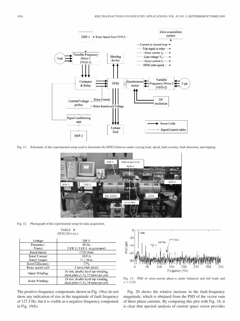
A test arrangement, as shown in Fig. 11 (schematic) andFig. 12 (test-bench snapshot), is used to test the rotor currentsand search-coil voltage of the DFIG under varying load, speed,and fault conditions. The DFIG is a three-phase 1.5-kV · A208-V 60-Hz slip-ring induction generator, which is mechan-ically coupled to a 2-kW synchronous motor run at differentspeed set points using an inverter. Both stator and rotor areconnected in star. The DFIG is run as a 60-Hz stand-alone gen-
erator connected to a three-phase load. The stator voltage andfrequency of the DFIG are controlled by feeding the rotor withslip frequency voltage using VFD-1. Taps are brought out ofthe DFIG to create stator fault. The stator phase has 144 turns.VFD-1 is a three-phase voltage source inverter (VSI) witha front-end diode bridge rectifier. A digital signal processor(DSP-1) TMS320F2812 generates the gating signals for theVSI. Using a timer relay and a contactor, the windings can beshorted for a period of 2–10 s for testing. During the shortedperiod, the data acquisition system samples the signals andfeeds it to a computer for data logging and further analysis.Special care was taken in shielding the cables, and excellentnoise rejection could be obtained (see Fig. 31 in the Appendix).The complete DFIG details have been presented in Table II.
A. Comparison of Rotor-Phase-u Current PSD UnderDifferent Operating Conditions
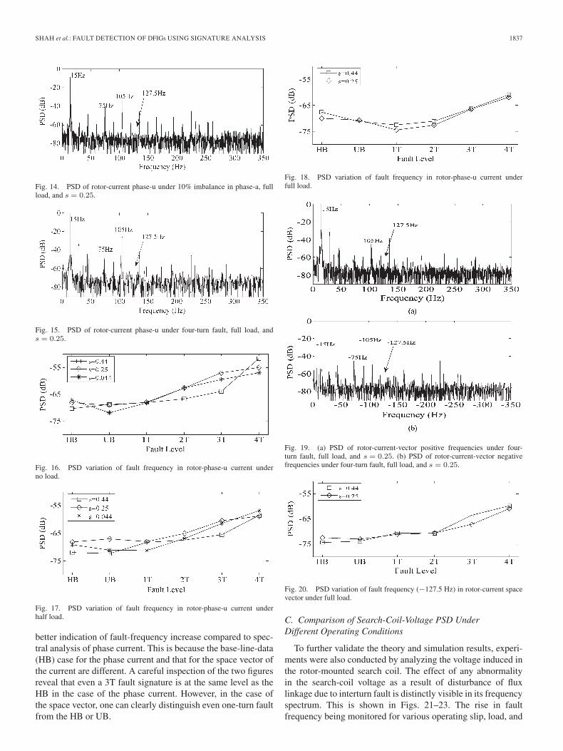
Figs. 13–15 show the spectrum of rotor current in phase-uunder different fault conditions when the DFIG is operating atfull-load and s = 0.25 (speed = 1350 r/min). The PSD plotsare obtained by analyzing 10 s of rotor-current time signalin MATLAB1 using the PSD function. Note that the 82.5-Hzcomponent did not show significant increase. The increase ofthe 127.5-Hz component is quite noticeable. The rise in faultfrequency that is monitored for various operating slip, load, andfault conditions is graphically shown in Figs. 16–18.
From the plots, it is evident that the magnitude level of faultfrequency rises with severity of faults. However, as the load isincreased, the magnitude of fault frequency for one-turn faultsdoes not increase significantly to indicate a fault. This can beattributed to the fact that, while shorting the turn, the impedanceof the lead wires adds up with the impedance of the shortedturn. It was determined experimentally that the shorting leadimpedance is roughly equal to the impedance of a one-turn coil.This severely affects the sensitivity of one-turn fault detection.
Also, as the generator load increases, the induced voltageper turn decreases, which may worsen sensitivity when theoutput voltage is not compensated for load variation. However,in the case of the actual dead-bolt fault, there will be no contactimpedance, and hence, sensitivity will be much better. Improve-ment can also be achieved by applying least-squares-basedmethods to compensate loading and time-harmonic effects. Atpresent, this investigation has been proposed as a subject forfuture work. Successful results have already been obtained forsquirrel-cage induction motors [16].
B. Comparison of PSD of Rotor-Phase-u Current WithSpace Vector of Rotor-Phase-u, Rotor-Phase-v, andRotor-Phase-w Currents
Further analysis was conducted to verify if the PSD of thespace vector of rotor-phase currents Iu, Iv , and Iw, given byIu + αIv + α2Iw, α = ej(2π/3), can show better resolution inthe increase of the fault-frequency magnitude level when com-pared to the results obtained by the PSD of phase current Iu.
1MATLAB, The MathWorks, Inc., Natick, MA.
1836 IEEE TRANSACTIONS ON INDUSTRY APPLICATIONS, VOL. 45, NO. 5, SEPTEMBER/OCTOBER 2009
Fig. 11. Schematic of the experimental setup used to determine the DFIG behavior under varying load, speed, fault severity, fault detection, and tripping.
Fig. 12. Photograph of the experimental setup for data acquisition.
TABLE IIDFIG DETAILS
The positive-frequency components shown in Fig. 19(a) do notshow any indication of rise in the magnitude of fault frequencyof 127.5 Hz, but it is visible as a negative-frequency componentin Fig. 19(b).
Fig. 13. PSD of rotor-current phase-u under balanced and full loads ands = 0.25.
Fig. 20 shows the relative increase in the fault-frequencymagnitude, which is obtained from the PSD of the vector sumof three phase currents. By comparing this plot with Fig. 18, itis clear that spectral analysis of current space vector provides
SHAH et al.: FAULT DETECTION OF DFIGs USING SIGNATURE ANALYSIS 1837
Fig. 14. PSD of rotor-current phase-u under 10% imbalance in phase-a, fullload, and s = 0.25.
Fig. 15. PSD of rotor-current phase-u under four-turn fault, full load, ands = 0.25.
Fig. 16. PSD variation of fault frequency in rotor-phase-u current underno load.
Fig. 17. PSD variation of fault frequency in rotor-phase-u current underhalf load.
better indication of fault-frequency increase compared to spec-tral analysis of phase current. This is because the base-line-data(HB) case for the phase current and that for the space vector ofthe current are different. A careful inspection of the two figuresreveal that even a 3T fault signature is at the same level as theHB in the case of the phase current. However, in the case ofthe space vector, one can clearly distinguish even one-turn faultfrom the HB or UB.
Fig. 18. PSD variation of fault frequency in rotor-phase-u current underfull load.
Fig. 19. (a) PSD of rotor-current-vector positive frequencies under four-turn fault, full load, and s = 0.25. (b) PSD of rotor-current-vector negativefrequencies under four-turn fault, full load, and s = 0.25.
Fig. 20. PSD variation of fault frequency (−127.5 Hz) in rotor-current spacevector under full load.
C. Comparison of Search-Coil-Voltage PSD UnderDifferent Operating Conditions
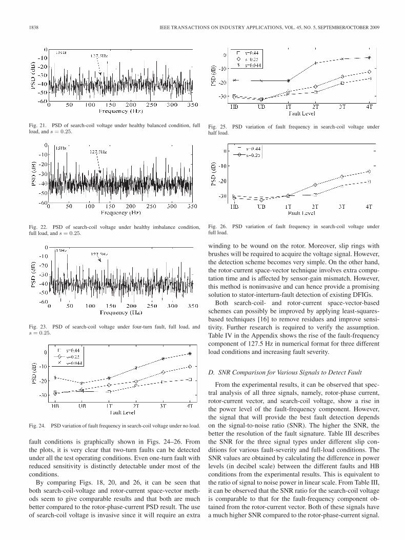
To further validate the theory and simulation results, experi-ments were also conducted by analyzing the voltage induced inthe rotor-mounted search coil. The effect of any abnormalityin the search-coil voltage as a result of disturbance of fluxlinkage due to interturn fault is distinctly visible in its frequencyspectrum. This is shown in Figs. 21–23. The rise in faultfrequency being monitored for various operating slip, load, and
1838 IEEE TRANSACTIONS ON INDUSTRY APPLICATIONS, VOL. 45, NO. 5, SEPTEMBER/OCTOBER 2009
Fig. 21. PSD of search-coil voltage under healthy balanced condition, fullload, and s = 0.25.
Fig. 22. PSD of search-coil voltage under healthy imbalance condition,full load, and s = 0.25.
Fig. 23. PSD of search-coil voltage under four-turn fault, full load, ands = 0.25.
Fig. 24. PSD variation of fault frequency in search-coil voltage under no load.
fault conditions is graphically shown in Figs. 24–26. Fromthe plots, it is very clear that two-turn faults can be detectedunder all the test operating conditions. Even one-turn fault withreduced sensitivity is distinctly detectable under most of theconditions.
By comparing Figs. 18, 20, and 26, it can be seen thatboth search-coil-voltage and rotor-current space-vector meth-ods seem to give comparable results and that both are muchbetter compared to the rotor-phase-current PSD result. The useof search-coil voltage is invasive since it will require an extra
Fig. 25. PSD variation of fault frequency in search-coil voltage underhalf load.
Fig. 26. PSD variation of fault frequency in search-coil voltage underfull load.
winding to be wound on the rotor. Moreover, slip rings withbrushes will be required to acquire the voltage signal. However,the detection scheme becomes very simple. On the other hand,the rotor-current space-vector technique involves extra compu-tation time and is affected by sensor-gain mismatch. However,this method is noninvasive and can hence provide a promisingsolution to stator-interturn-fault detection of existing DFIGs.
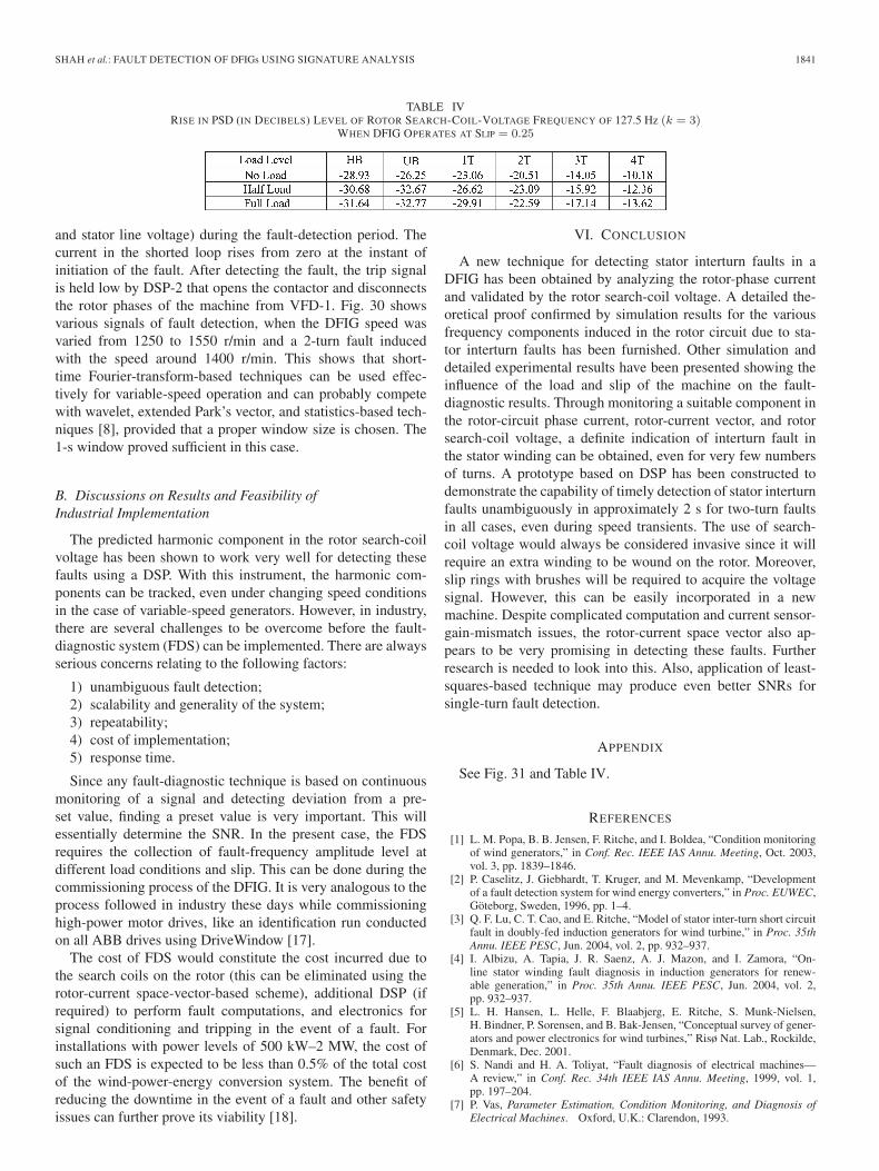
Both search-coil- and rotor-current space-vector-basedschemes can possibly be improved by applying least-squares-based techniques [16] to remove residues and improve sensi-tivity. Further research is required to verify the assumption.Table IV in the Appendix shows the rise of the fault-frequencycomponent of 127.5 Hz in numerical format for three differentload conditions and increasing fault severity.
D. SNR Comparison for Various Signals to Detect Fault
From the experimental results, it can be observed that spec-tral analysis of all three signals, namely, rotor-phase current,rotor-current vector, and search-coil voltage, show a rise inthe power level of the fault-frequency component. However,the signal that will provide the best fault detection dependson the signal-to-noise ratio (SNR). The higher the SNR, thebetter the resolution of the fault signature. Table III describesthe SNR for the three signal types under different slip con-ditions for various fault-severity and full-load conditions. TheSNR values are obtained by calculating the difference in powerlevels (in decibel scale) between the different faults and HBconditions from the experimental results. This is equivalent tothe ratio of signal to noise power in linear scale. From Table III,it can be observed that the SNR ratio for the search-coil voltageis comparable to that for the fault-frequency component ob-tained from the rotor-current vector. Both of these signals havea much higher SNR compared to the rotor-phase-current signal.
SHAH et al.: FAULT DETECTION OF DFIGs USING SIGNATURE ANALYSIS 1839
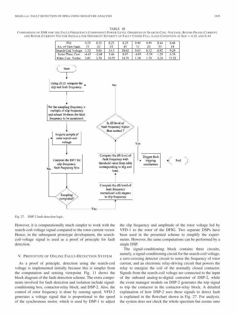
TABLE IIICOMPARISON OF SNR FOR THE FAULT-FREQUENCY-COMPONENT POWER LEVEL OBSERVED IN SEARCH-COIL-VOLTAGE, ROTOR-PHASE-CURRENT,
AND ROTOR-CURRENT-VECTOR SIGNALS FOR DIFFERENT SEVERITY OF FAULT UNDER FULL-LOAD CONDITION AT SLIP = 0.25 AND 0.44
Fig. 27. DSP-2 fault-detection logic.
However, it is computationally much simpler to work with thesearch-coil-voltage signal compared to the rotor-current vector.Hence, in the subsequent prototype development, the search-coil-voltage signal is used as a proof of principle for faultdetection.
V. PROTOTYPE OF ONLINE FAULT-DETECTION SYSTEM
As a proof of principle, detection using the search-coilvoltage is implemented initially because this is simpler fromthe computation and sensing viewpoint. Fig. 11 shows theblock diagram of the fault-detection scheme. The extra compo-nents involved for fault detection and isolation include signal-conditioning box, contactor-relay block, and DSP-2. Also, thecontrol of rotor frequency is done by sensing speed. VFD-2generates a voltage signal that is proportional to the speedof the synchronous motor, which is used by DSP-1 to adjust
the slip frequency and amplitude of the rotor voltage fed byVFD-1 to the rotor of the DFIG. Two separate DSPs havebeen used in the presented scheme to simplify the experi-ments. However, the same computations can be performed by asingle DSP.
The signal-conditioning block contains three circuits,namely, a signal-conditioning circuit for the search-coil voltage,a zero-crossing detector circuit to sense the frequency of rotorcurrent, and an electronic relay-driving circuit that powers therelay to energize the coil of the normally closed contactor.Signals from the search-coil voltage are connected to the inputof the onboard analog-to-digital converter of DSP-2, whilethe event manager module on DSP-2 generates the trip signalto trip the contactor in the contactor-relay block. A detailedexplanation of how DSP-2 uses these signals to detect faultis explained in the flowchart shown in Fig. 27. For analysis,the system does not check the whole spectrum but zooms onto
1840 IEEE TRANSACTIONS ON INDUSTRY APPLICATIONS, VOL. 45, NO. 5, SEPTEMBER/OCTOBER 2009
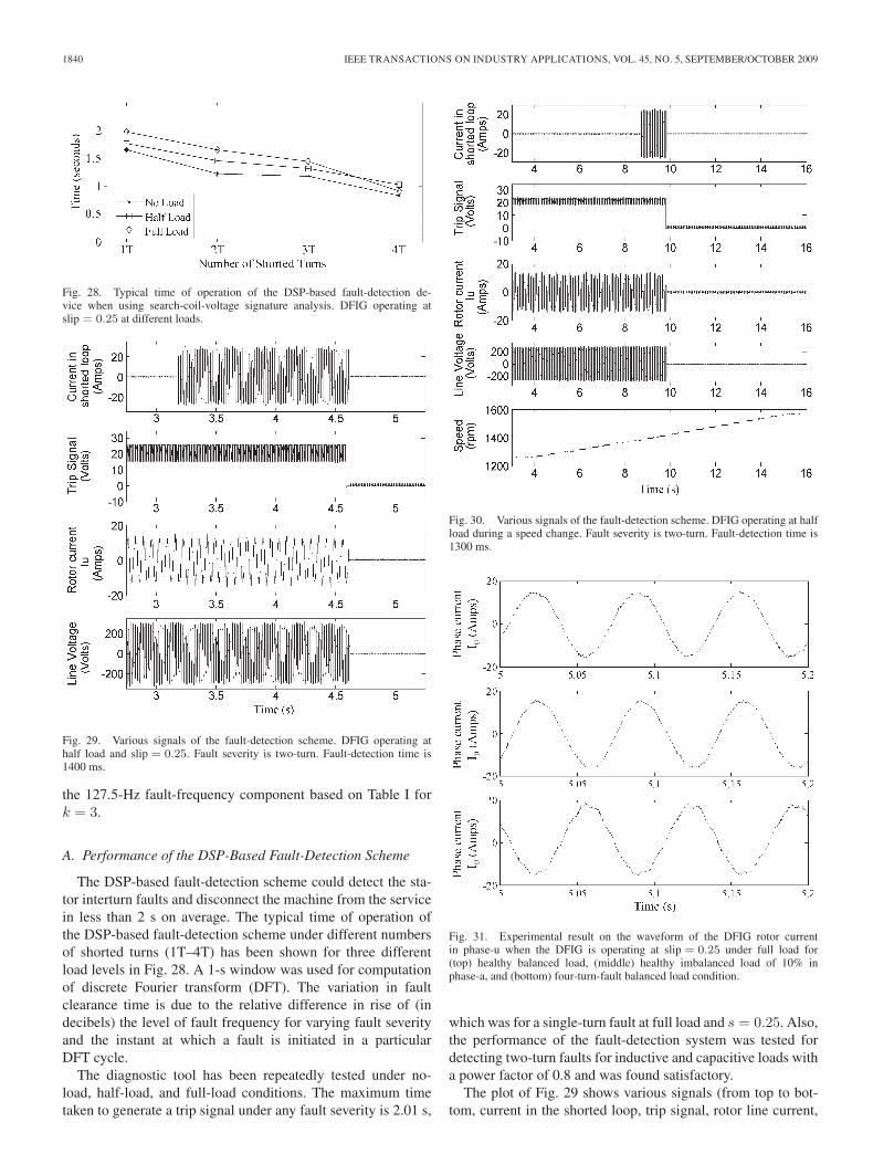
Fig. 28. Typical time of operation of the DSP-based fault-detection de-vice when using search-coil-voltage signature analysis. DFIG operating atslip = 0.25 at different loads.
Fig. 29. Various signals of the fault-detection scheme. DFIG operating athalf load and slip = 0.25. Fault severity is two-turn. Fault-detection time is1400 ms.
the 127.5-Hz fault-frequency component based on Table I fork = 3.
A. Performance of the DSP-Based Fault-Detection Scheme
The DSP-based fault-detection scheme could detect the sta-tor interturn faults and disconnect the machine from the servicein less than 2 s on average. The typical time of operation ofthe DSP-based fault-detection scheme under different numbersof shorted turns (1T–4T) has been shown for three differentload levels in Fig. 28. A 1-s window was used for computationof discrete Fourier transform (DFT). The variation in faultclearance time is due to the relative difference in rise of (indecibels) the level of fault frequency for varying fault severityand the instant at which a fault is initiated in a particularDFT cycle.
The diagnostic tool has been repeatedly tested under no-load, half-load, and full-load conditions. The maximum timetaken to generate a trip signal under any fault severity is 2.01 s,
Fig. 30. Various signals of the fault-detection scheme. DFIG operating at halfload during a speed change. Fault severity is two-turn. Fault-detection time is1300 ms.
Fig. 31. Experimental result on the waveform of the DFIG rotor currentin phase-u when the DFIG is operating at slip = 0.25 under full load for(top) healthy balanced load, (middle) healthy imbalanced load of 10% inphase-a, and (bottom) four-turn-fault balanced load condition.
which was for a single-turn fault at full load and s = 0.25. Also,the performance of the fault-detection system was tested fordetecting two-turn faults for inductive and capacitive loads witha power factor of 0.8 and was found satisfactory.
The plot of Fig. 29 shows various signals (from top to bot-tom, current in the shorted loop, trip signal, rotor line current,
SHAH et al.: FAULT DETECTION OF DFIGs USING SIGNATURE ANALYSIS 1841
TABLE IVRISE IN PSD (IN DECIBELS) LEVEL OF ROTOR SEARCH-COIL-VOLTAGE FREQUENCY OF 127.5 Hz (k = 3)
WHEN DFIG OPERATES AT SLIP = 0.25
and stator line voltage) during the fault-detection period. Thecurrent in the shorted loop rises from zero at the instant ofinitiation of the fault. After detecting the fault, the trip signalis held low by DSP-2 that opens the contactor and disconnectsthe rotor phases of the machine from VFD-1. Fig. 30 showsvarious signals of fault detection, when the DFIG speed wasvaried from 1250 to 1550 r/min and a 2-turn fault inducedwith the speed around 1400 r/min. This shows that short-time Fourier-transform-based techniques can be used effec-tively for variable-speed operation and can probably competewith wavelet, extended Park’s vector, and statistics-based tech-niques [8], provided that a proper window size is chosen. The1-s window proved sufficient in this case.
B. Discussions on Results and Feasibility ofIndustrial Implementation
The predicted harmonic component in the rotor search-coilvoltage has been shown to work very well for detecting thesefaults using a DSP. With this instrument, the harmonic com-ponents can be tracked, even under changing speed conditionsin the case of variable-speed generators. However, in industry,there are several challenges to be overcome before the fault-diagnostic system (FDS) can be implemented. There are alwaysserious concerns relating to the following factors:
1) unambiguous fault detection;2) scalability and generality of the system;3) repeatability;4) cost of implementation;5) response time.
Since any fault-diagnostic technique is based on continuousmonitoring of a signal and detecting deviation from a pre-set value, finding a preset value is very important. This willessentially determine the SNR. In the present case, the FDSrequires the collection of fault-frequency amplitude level atdifferent load conditions and slip. This can be done during thecommissioning process of the DFIG. It is very analogous to theprocess followed in industry these days while commissioninghigh-power motor drives, like an identification run conductedon all ABB drives using DriveWindow [17].
The cost of FDS would constitute the cost incurred due tothe search coils on the rotor (this can be eliminated using therotor-current space-vector-based scheme), additional DSP (ifrequired) to perform fault computations, and electronics forsignal conditioning and tripping in the event of a fault. Forinstallations with power levels of 500 kW–2 MW, the cost ofsuch an FDS is expected to be less than 0.5% of the total costof the wind-power-energy conversion system. The benefit ofreducing the downtime in the event of a fault and other safetyissues can further prove its viability [18].
VI. CONCLUSION
A new technique for detecting stator interturn faults in aDFIG has been obtained by analyzing the rotor-phase currentand validated by the rotor search-coil voltage. A detailed the-oretical proof confirmed by simulation results for the variousfrequency components induced in the rotor circuit due to sta-tor interturn faults has been furnished. Other simulation anddetailed experimental results have been presented showing theinfluence of the load and slip of the machine on the fault-diagnostic results. Through monitoring a suitable component inthe rotor-circuit phase current, rotor-current vector, and rotorsearch-coil voltage, a definite indication of interturn fault inthe stator winding can be obtained, even for very few numbersof turns. A prototype based on DSP has been constructed todemonstrate the capability of timely detection of stator interturnfaults unambiguously in approximately 2 s for two-turn faultsin all cases, even during speed transients. The use of search-coil voltage would always be considered invasive since it willrequire an extra winding to be wound on the rotor. Moreover,slip rings with brushes will be required to acquire the voltagesignal. However, this can be easily incorporated in a newmachine. Despite complicated computation and current sensor-gain-mismatch issues, the rotor-current space vector also ap-pears to be very promising in detecting these faults. Furtherresearch is needed to look into this. Also, application of least-squares-based technique may produce even better SNRs forsingle-turn fault detection.
APPENDIX
See Fig. 31 and Table IV.
REFERENCES
[1] L. M. Popa, B. B. Jensen, F. Ritche, and I. Boldea, “Condition monitoringof wind generators,” in Conf. Rec. IEEE IAS Annu. Meeting, Oct. 2003,vol. 3, pp. 1839–1846.
[2] P. Caselitz, J. Giebhardt, T. Kruger, and M. Mevenkamp, “Developmentof a fault detection system for wind energy converters,” in Proc. EUWEC,Göteborg, Sweden, 1996, pp. 1–4.
[3] Q. F. Lu, C. T. Cao, and E. Ritche, “Model of stator inter-turn short circuitfault in doubly-fed induction generators for wind turbine,” in Proc. 35thAnnu. IEEE PESC, Jun. 2004, vol. 2, pp. 932–937.
[4] I. Albizu, A. Tapia, J. R. Saenz, A. J. Mazon, and I. Zamora, “On-line stator winding fault diagnosis in induction generators for renew-able generation,” in Proc. 35th Annu. IEEE PESC, Jun. 2004, vol. 2,pp. 932–937.
[5] L. H. Hansen, L. Helle, F. Blaabjerg, E. Ritche, S. Munk-Nielsen,H. Bindner, P. Sorensen, and B. Bak-Jensen, “Conceptual survey of gener-ators and power electronics for wind turbines,” Risø Nat. Lab., Rockilde,Denmark, Dec. 2001.
[6] S. Nandi and H. A. Toliyat, “Fault diagnosis of electrical machines—A review,” in Conf. Rec. 34th IEEE IAS Annu. Meeting, 1999, vol. 1,pp. 197–204.
[7] P. Vas, Parameter Estimation, Condition Monitoring, and Diagnosis ofElectrical Machines. Oxford, U.K.: Clarendon, 1993.
1842 IEEE TRANSACTIONS ON INDUSTRY APPLICATIONS, VOL. 45, NO. 5, SEPTEMBER/OCTOBER 2009
[8] H. Douglas, P. Pillay, and P. Barendse, “The detection of inter-turn statorfaults in doubly-fed induction generators,” in Conf. Rec. 40th IEEE IASAnnu. Meeting, Oct. 2–6, 2005, vol. 2, pp. 1097–1102.
[9] T. Wildi, Electrical Machines, Drives, and Power Systems., 6th ed.Englewood Cliffs, NJ: Prentice-Hall, 2005.
[10] W. T. Thomson, “On-line MCSA to diagnose shorted turns in low voltagestator windings of 3-phase induction motors prior to failure,” in Proc.IEEE-IEMDC, 2001, vol. 1, pp. 891–898.
[11] J. A. Baroudi, V. R. Dinavahi, and A. M. Knight, “A review of powerconverter topologies for wind generators,” in Proc. IEEE Int. Elect. Mach.Drives, May 15–18, 2005, vol. 1, pp. 458–465.
[12] D. Casadei, F. Filippetti, C. Rossi, A. Stefani, A. Yazidi, andG. A. Capolino, “Diagnostic technique based on rotor modulating signalssignature analysis for doubly fed induction machines in wind generatorsystems,” in Conf. Rec. 41st IEEE IAS Annu. Meeting, Oct. 8–12, 2006,vol. 3, pp. 1525–1532.
[13] S. Nandi, “Space and time harmonics related problems and their miti-gation for position and speed sensorless slip-ring induction motor drivesapplications,” Sadhana, vol. 33, pt. 5, pp. 565–580, Oct. 2008.
[14] J. Penman, H. G. Sedding, B. A. Lloyd, and W. T. Fink, “Detectionand location of interturn short circuits in the stator windings of operat-ing motors,” IEEE Trans. Energy Convers., vol. 9, no. 4, pp. 652–658,Dec. 1994.
[15] H. A. Toliyat and T. A. Lipo, “Transient analysis of cage induction ma-chines under stator, rotor bar and end ring faults,” IEEE Trans. EnergyConvers., vol. 10, no. 2, pp. 241–247, Jun. 1995.
[16] Q. Wu, “Single-turn sensitive stator inter-turn fault detection of inductionmachines,” M.S. thesis, Univ. Victoria, Victoria, BC, Canada, 2008.
[17] ABB, DriveWindow Software, Datasheet. [Online]. Available: http://library.abb.com/global/scot/scot201.nsf/veritydisplay/a5ae37d539433eacc2256eed00217b2e/$File/DriveWindow_2_Leaflet.pdf
[18] J. Nilsson and L. Bertling, “Maintenance management of wind powersystems using condition monitoring systems—Life cycle cost analysis fortwo case studies,” IEEE Trans. Energy Convers., vol. 22, no. 1, pp. 223–229, Mar. 2007.
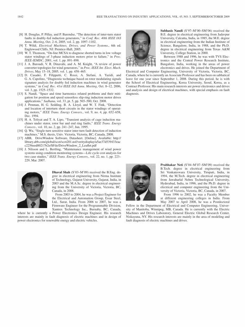
Dhaval Shah (S’03–M’09) received the B.Eng. de-gree in electrical engineering from Nirma Instituteof Technology, Gujarat University, Gujarat, India, in2003 and the M.A.Sc. degree in electrical engineer-ing from the University of Victoria, Victoria, BC,Canada, in 2008.
From 2003 to 2004, he was a Project Engineer forthe Electrical and Automation Group, Essar Steel,Ltd., Surat, India. From 2006 to 2007, he was aFirmware Engineer for the Programmable Division,Xantrex Technology Inc., Burnaby, BC, Canada,
where he is currently a Power Electronics Design Engineer. His researchinterests are mainly in fault diagnosis of electric machines and in design ofpower electronics for renewable energy and electric vehicles.
Subhasis Nandi (S’97–M’00–SM’06) received theB.E. degree in electrical engineering from JadavpurUniversity, Calcutta, India, in 1985, the M.E. degreein electrical engineering from the Indian Institute ofScience, Bangalore, India, in 1988, and the Ph.D.degree in electrical engineering from Texas A&MUniversity, College Station, in 2000.
Between 1988 and 1996, he was with TVS Elec-tronics and the Central Power Research Institute,Bangalore, India, working in the areas of powerelectronics and drives. He joined the Department of
Electrical and Computer Engineering, University of Victoria, Victoria, BC,Canada, where he is currently an Associate Professor and has been on sabbaticalleave for one year since September 1, 2008. During this period, he is withthe School of Electrical Engineering, Korea University, Seoul, Korea, as aContract Professor. His main research interests are power electronics and drivesand analysis and design of electrical machines, with special emphasis on faultdiagnosis.
Prabhakar Neti (S’04–M’07–SM’09) received theB.Tech. degree in electrical engineering fromSri Venkateswara University, Tirupati, India, in1994, the M.Tech. degree in electrical engineeringfrom Jawaharlal Nehru Technological University,Hyderabad, India, in 1996, and the Ph.D. degree inelectrical and computer engineering from the Uni-versity of Victoria, Victoria, BC, Canada, in 2007.
From 1996 to 2002, he was a Faculty Memberat different engineering colleges in India. FromMay 2007 to April 2008, he was a Postdoctoral
Fellow in the Department of Electrical and Computer Engineering, Univer-sity of Manitoba, Winnipeg, MB, Canada. He is currently with the ElectricMachines and Drives Laboratory, General Electric Global Research Center,Niskayuna, NY. His research interests are mainly in the area of modeling andfault diagnosis of electric machines and drives.


