Embed Size (px)
Citation preview
05 V 018 E
Certifi ed QualityManagement System
ID: 2912
PRESENTATION
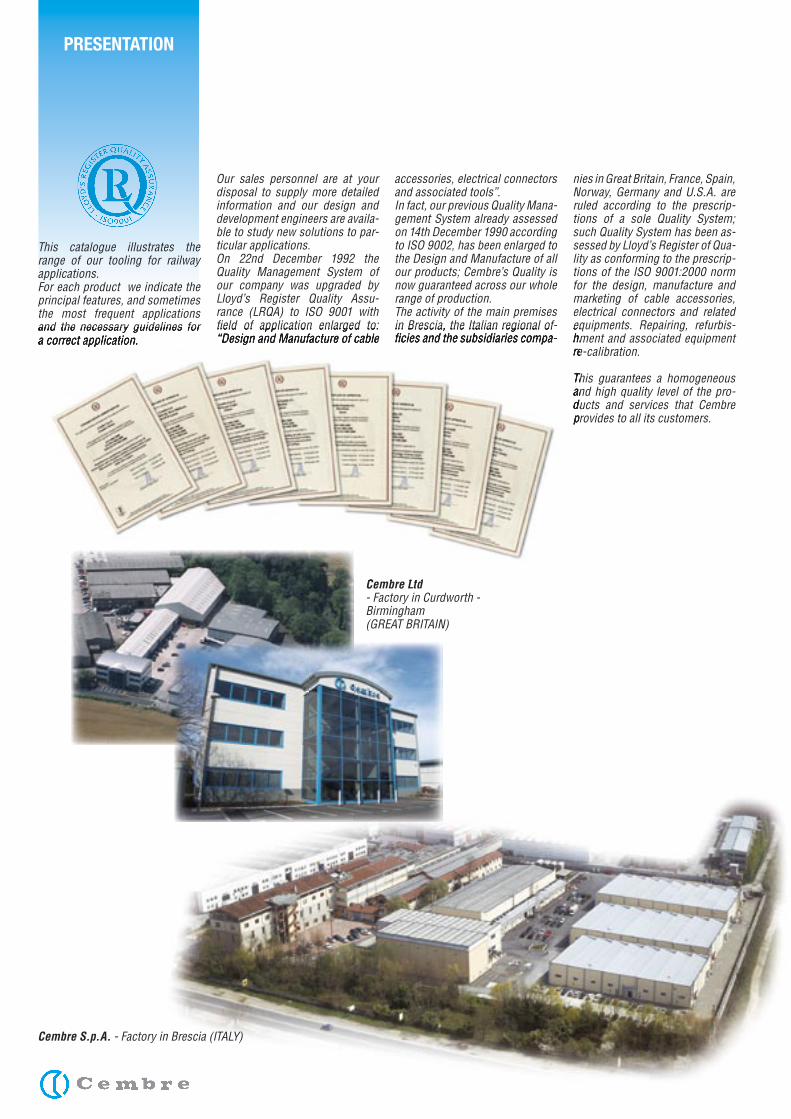
Our sales personnel are at your disposal to supply more detailed information and our design and development engineers are availa-ble to study new solutions to par-ticular applications.On 22nd December 1992 the Quality Management System of our company was upgraded by Lloyd’s Register Quality Assu-rance (LRQA) to ISO 9001 with fi eld of application enlarged to: “Design and Manufacture of cable
accessories, electrical connectors and associated tools”.In fact, our previous Quality Mana-gement System already assessed on 14th December 1990 according to ISO 9002, has been enlarged to the Design and Manufacture of all our products; Cembre’s Quality is now guaranteed across our whole range of production.The activity of the main premises in Brescia, the Italian regional of-fi cies and the subsidiaries compa-
nies in Great Britain, France, Spain, Norway, Germany and U.S.A. are ruled according to the prescrip-tions of a sole Quality System; such Quality System has been as-sessed by Lloyd’s Register of Qua-lity as conforming to the prescrip-tions of the ISO 9001:2000 norm for the design, manufacture and marketing of cable accessories, electrical connectors and related equipments. Repairing, refurbis-hment and associated equipment re-calibration.
This guarantees a homogeneous and high quality level of the pro-ducts and services that Cembre provides to all its customers.
This catalogue illustrates the range of our tooling for railway applications.For each product we indicate the principal features, and sometimes the most frequent applications and the necessary guidelines for a correct application.
Cembre Ltd- Factory in Curdworth -Birmingham(GREAT BRITAIN)
Cembre S.p.A. - Factory in Brescia (ITALY)
fi eld of application enlarged to: “Design and Manufacture of cable
in Brescia, the Italian regional of-fi cies and the subsidiaries compa-
equipments. Repairing, refurbis-hment and associated equipment re-calibration.
This guarantees a homogeneous and high quality level of the pro-ducts and services that Cembre provides to all its customers.
and the necessary guidelines for a correct application.
Cembre Ltd
– 1 –
RAIL DRILLING MACHINES ..................................................................................................................... Page 2 - 5
STANDARD ACCESSORIES FOR RAIL DRILLING MACHINES .......................................................................... Page 6
OPTIONAL ACCESSORIES SUPPLIED WITH RAIL DRILLING MACHINES ........................................................... Page 7 - 11
EXAMPLES OF RAIL DRILLING MACHINE APPLICATIONS .............................................................................. Page 12
MOBILE UNIT FOR DRILLING WOODEN SLEEPERS ..................................................................................... Page 13 - 14
PORTABLE DRILLING MACHINES FOR WOODEN SLEEPERS ......................................................................... Page 15 - 17
PANDROL ‘‘E CLIP’’ INSERTION/EXTRACTION MACHINE ............................................................................... Page 18 - 19
PANDROL ‘‘FAST CLIP’’ INSERTION/EXTRACTION MACHINE ......................................................................... Page 20 - 21
IMPACT WRENCH ..�................................................................................................................................ Page 22 - 23
CONNECTING JOINTS FOR PROFILES CONTACT WIRES ................................................................................ Page 24
HYDRAULIC CUTTING HEAD FOR PROFILES CONTACT WIRE ........................................................................ Page 25
HYDRAULIC CUTTING TOOLS FOR PROFILED CONTACT WIRE ....................................................................... Page 26
HYDRAULIC SYSTEMS FOR RAIL WEB ELECTRICAL CONNECTIONS ............................................................... Page 27 - 28
HYDRAULIC NUT SPLITTING HEADS ......................................................................................................... Page 29
HYDRAULIC CRIMPING TOOLS ............................................................................................................... Page 30 - 31
HYDRAULIC CRIMPING HEADS ............................................................................................................... Page 32 - 33
HYDRAULIC CABLE CUTTERS ................................................................................................................. Page 34 - 37
HYDRAULIC PUMPS & ACCESSORIES ...................................................................................................... Page 38 - 39
CEMBRE RAIL BONDS ........................................................................................................................... Page 40
OTHER CEMBRE PRODUCTS .................................................................................................................. Page 41
INDEX
– 2 –
RAIL DRILLING MACHINES
LD-1P
LD-2E
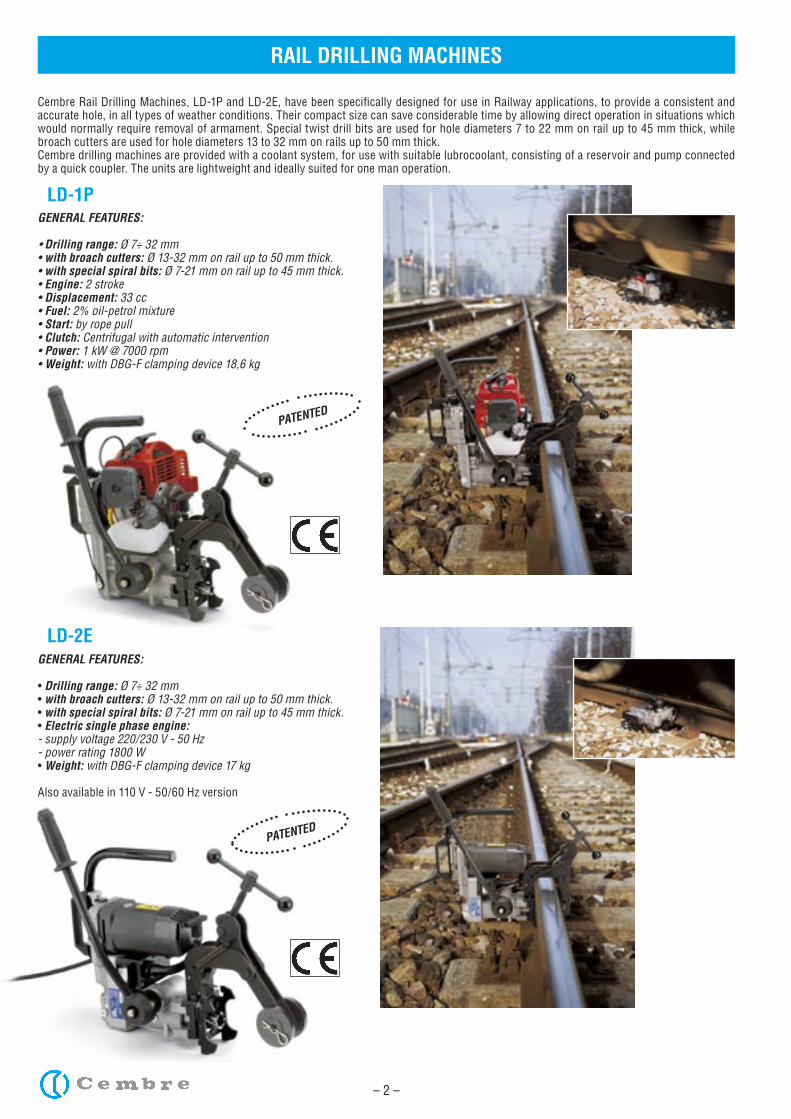
Cembre Rail Drilling Machines, LD-1P and LD-2E, have been specifically designed for use in Railway applications, to provide a consistent and accurate hole, in all types of weather conditions. Their compact size can save considerable time by allowing direct operation in situations which would normally require removal of armament. Special twist drill bits are used for hole diameters 7 to 22 mm on rail up to 45 mm thick, while broach cutters are used for hole diameters 13 to 32 mm on rails up to 50 mm thick.Cembre drilling machines are provided with a coolant system, for use with suitable lubrocoolant, consisting of a reservoir and pump connected by a quick coupler. The units are lightweight and ideally suited for one man operation.
GENERAL FEATURES: • Drilling range: Ø 7÷ 32 mm• with broach cutters: Ø 13-32 mm on rail up to 50 mm thick.• with special spiral bits: Ø 7-21 mm on rail up to 45 mm thick.• Engine: 2 stroke• Displacement: 33 cc• Fuel: 2% oil-petrol mixture• Start: by rope pull• Clutch: Centrifugal with automatic intervention• Power: 1 kW @ 7000 rpm• Weight: with DBG-F clamping device 18,6 kg
GENERAL FEATURES:
• Drilling range: Ø 7÷ 32 mm• with broach cutters: Ø 13-32 mm on rail up to 50 mm thick.• with special spiral bits: Ø 7-21 mm on rail up to 45 mm thick.• Electric single phase engine:- supply voltage 220/230 V - 50 Hz- power rating 1800 W• Weight: with DBG-F clamping device 17 kg
Also available in 110 V - 50/60 Hz version
PATENTED
PATENTED
– 3 –
RAIL DRILLING MACHINES
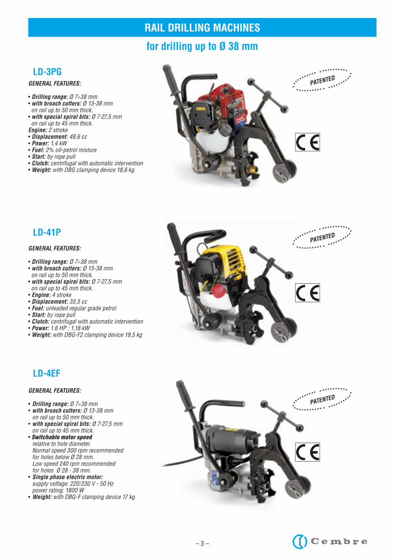
LD-3PG
LD-41P
LD-4EF
for drilling up to Ø 38 mm
PATENTED
PATENTED
PATENTED
GENERAL FEATURES:
• Drilling range: Ø 7÷38 mm• with broach cutters: Ø 13-38 mm on rail up to 50 mm thick.• with special spiral bits: Ø 7-27,5 mm on rail up to 45 mm thick.Engine: 2 stroke• Displacement: 48,6 cc• Power: 1,4 kW• Fuel: 2% oil-petrol mixture• Start: by rope pull• Clutch: centrifugal with automatic intervention• Weight: with DBG clamping device 18,6 kg
GENERAL FEATURES:
• Drilling range: Ø 7÷38 mm• with broach cutters: Ø 13-38 mm on rail up to 50 mm thick.• with special spiral bits: Ø 7-27,5 mm on rail up to 45 mm thick.• Engine: 4 stroke• Displacement: 33,5 cc• Fuel: unleaded regular grade petrol• Start: by rope pull• Clutch: centrifugal with automatic intervention• Power: 1.6 HP ; 1,18 kW• Weight: with DBG-F2 clamping device 19,5 kg
GENERAL FEATURES:
• Drilling range: Ø 7÷38 mm• with broach cutters: Ø 13-38 mm on rail up to 50 mm thick.• with special spiral bits: Ø 7-27,5 mm on rail up to 45 mm thick.• Switchable motor speed relative to hole diameter. Normal speed 300 rpm recommended for holes below Ø 28 mm. Low speed 240 rpm recommended for holes Ø 28 - 38 mm. • Single phase electric motor: supply voltage: 220/230 V - 50 Hz power rating: 1800 W• Weight: with DBG-F clamping device 17 kg
– 4 –
RAIL DRILLING MACHINES
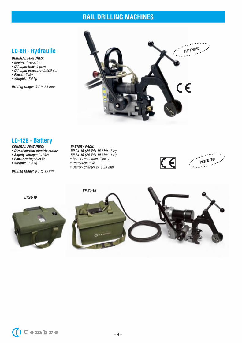
LD-8H - HydraulicGENERAL FEATURES:• Engine: hydraulic• Oil input flow: 5 gpm• Oil input pressure: 2.000 psi• Power: 2 kW• Weight: 17,5 kg
Drilling range: Ø 7 to 38 mm
PATENTED
PATENTED
LD-12B - BatteryGENERAL FEATURES:• Direct current electric motor• Supply voltage: 24 Vdc• Power rating: 345 W• Weight: 17,3 kg
Drilling range: Ø 7 to 19 mm
BATTERY PACK:BP 24-16 (24 Vdc 16 Ah): 17 kgBP 24-10 (24 Vdc 10 Ah): 11 kg• Battery condition display• Protection fuse• Battery charger 24 V 2A max
BP24-10
BP 24-16
– 5 –
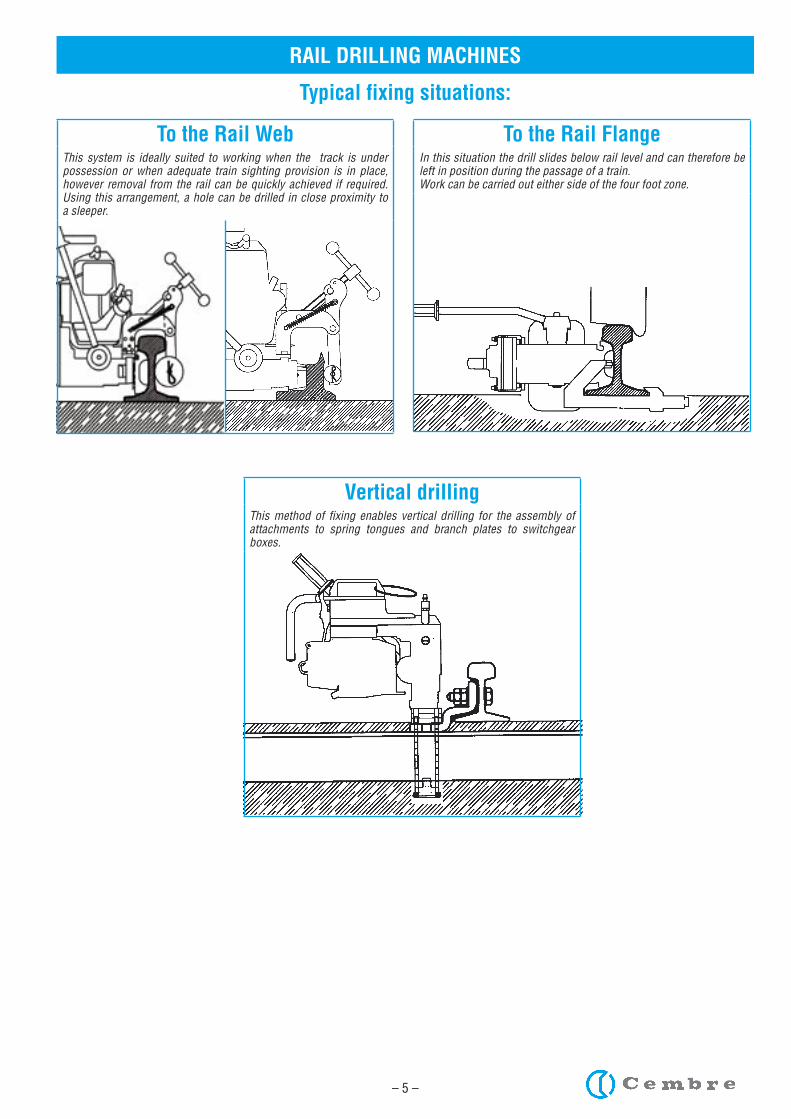
RAIL DRILLING MACHINES
Typical fixing situations:
To the Rail WebThis system is ideally suited to working when the track is under possession or when adequate train sighting provision is in place, however removal from the rail can be quickly achieved if required. Using this arrangement, a hole can be drilled in close proximity to a sleeper.
To the Rail FlangeIn this situation the drill slides below rail level and can therefore be left in position during the passage of a train.Work can be carried out either side of the four foot zone.
Vertical drillingThis method of fixing enables vertical drilling for the assembly of attachments to spring tongues and branch plates to switchgear boxes.
– 6 –
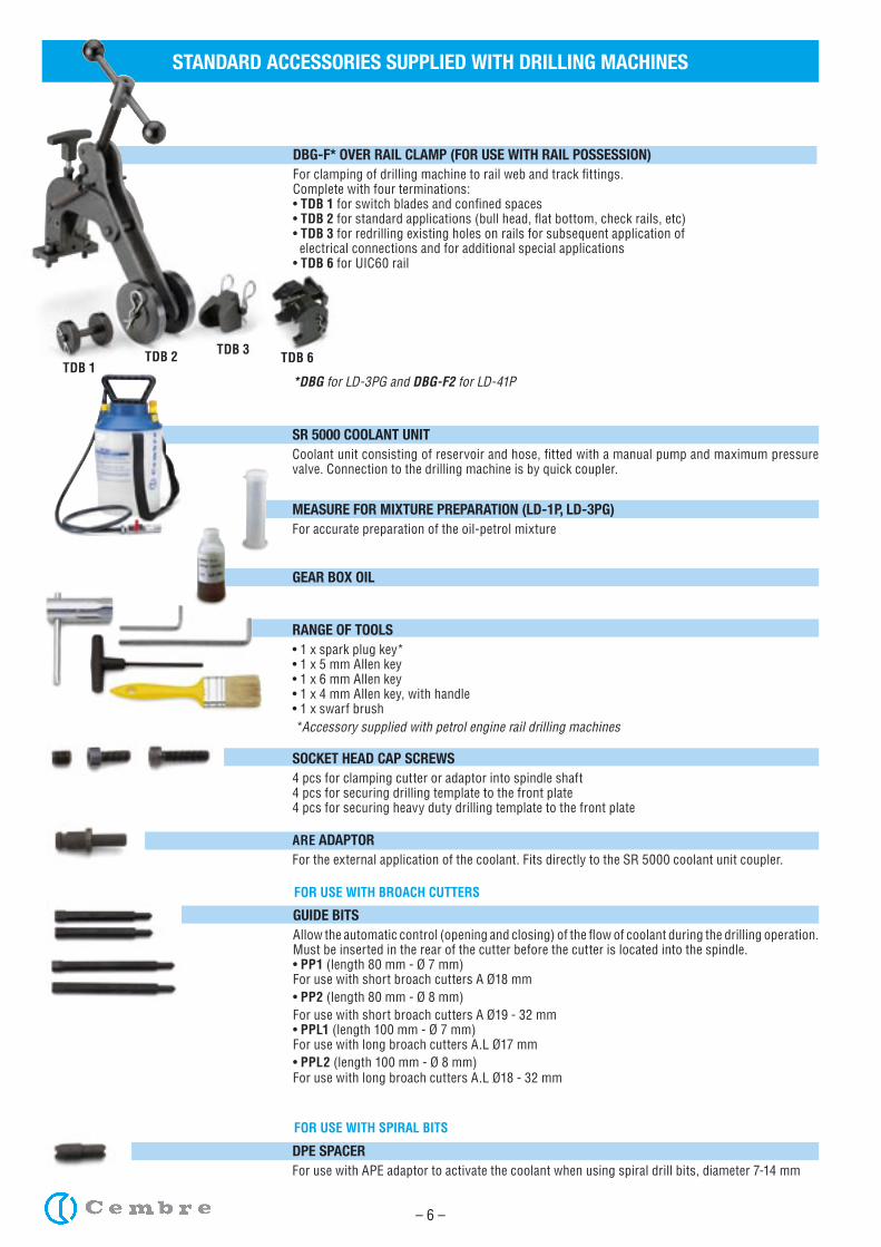
STANDARD ACCESSORIES SUPPLIED WITH DRILLING MACHINES
SR 5000 COOLANT UNITCoolant unit consisting of reservoir and hose, fitted with a manual pump and maximum pressure valve. Connection to the drilling machine is by quick coupler.
GUIDE BITSAllow the automatic control (opening and closing) of the flow of coolant during the drilling operation. Must be inserted in the rear of the cutter before the cutter is located into the spindle.• PP1 (length 80 mm - Ø 7 mm)For use with short broach cutters A Ø18 mm • PP2 (length 80 mm - Ø 8 mm)For use with short broach cutters A Ø19 - 32 mm • PPL1 (length 100 mm - Ø 7 mm)For use with long broach cutters A.L Ø17 mm• PPL2 (length 100 mm - Ø 8 mm)For use with long broach cutters A.L Ø18 - 32 mm
DBG-F* OVER RAIL CLAMP (FOR USE WITH RAIL POSSESSION)For clamping of drilling machine to rail web and track fittings.Complete with four terminations:• TDB 1 for switch blades and confined spaces• TDB 2 for standard applications (bull head, flat bottom, check rails, etc) • TDB 3 for redrilling existing holes on rails for subsequent application of electrical connections and for additional special applications• TDB 6 for UIC60 rail
*DBG for LD-3PG and DBG-F2 for LD-41P
MEASURE FOR MIXTURE PREPARATION (LD-1P, LD-3PG)For accurate preparation of the oil-petrol mixture
GEAR BOX OIL
TDB 1TDB 3TDB 2
*Accessory supplied with petrol engine rail drilling machines
DPE SPACERFor use with APE adaptor to activate the coolant when using spiral drill bits, diameter 7-14 mm
ARE ADAPTORFor the external application of the coolant. Fits directly to the SR 5000 coolant unit coupler.
SOCKET HEAD CAP SCREWS4 pcs for clamping cutter or adaptor into spindle shaft4 pcs for securing drilling template to the front plate4 pcs for securing heavy duty drilling template to the front plate
RANGE OF TOOLS• 1 x spark plug key*• 1 x 5 mm Allen key• 1 x 6 mm Allen key• 1 x 4 mm Allen key, with handle• 1 x swarf brush
TDB 6
FOR USE WITH BROACH CUTTERS
FOR USE WITH SPIRAL BITS
– 7 –
5 10 15 20 0–5–6–7–8–9
–10
%
T(°C)
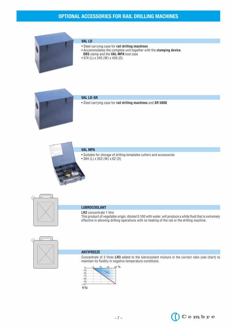
VAL LD• Steel carrying case for rail drilling machines• Accommodates the complete unit together with the clamping device, DBS clamp and the VAL-MPA tool case• 574 (L) x 345 (W) x 430 (D)
OPTIONAL ACCESSORIES FOR RAIL DRILLING MACHINES
VAL LD-SR• Steel carrying case for rail drilling machines and SR 5000
VAL MPA• Suitable for storage of drilling templates cutters and accessories• 384 (L) x 353 (W) x 62 (D)
LUBROCOOLANT LR2 concentrate 1 litre This product of vegetable origin, diluted 5:100 with water, will produce a white fluid that is extremely effective in allowing drilling operations with no heating of the rail or the drilling machine.
ANTIFREEZEConcentrate of 3 litres LR3 added to the lubrocoolant mixture in the correct ratio (see chart) to maintain its fluidity in negative temperature conditions.
– 8 –
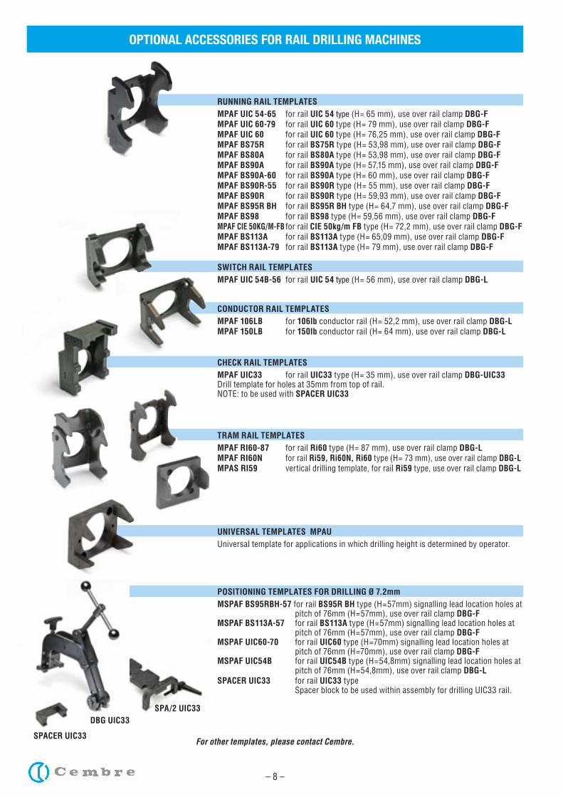
OPTIONAL ACCESSORIES FOR RAIL DRILLING MACHINES
RUNNING RAIL TEMPLATESMPAF UIC 54-65 for rail UIC 54 type (H= 65 mm), use over rail clamp DBG-FMPAF UIC 60-79 for rail UIC 60 type (H= 79 mm), use over rail clamp DBG-FMPAF UIC 60 for rail UIC 60 type (H= 76,25 mm), use over rail clamp DBG-FMPAF BS75R for rail BS75R type (H= 53,98 mm), use over rail clamp DBG-FMPAF BS80A for rail BS80A type (H= 53,98 mm), use over rail clamp DBG-FMPAF BS90A for rail BS90A type (H= 57,15 mm), use over rail clamp DBG-FMPAF BS90A-60 for rail BS90A type (H= 60 mm), use over rail clamp DBG-FMPAF BS90R-55 for rail BS90R type (H= 55 mm), use over rail clamp DBG-FMPAF BS90R for rail BS90R type (H= 59,93 mm), use over rail clamp DBG-FMPAF BS95R BH for rail BS95R BH type (H= 64,7 mm), use over rail clamp DBG-FMPAF BS98 for rail BS98 type (H= 59,56 mm), use over rail clamp DBG-FMPAF CIE 50KG/M-FB for rail CIE 50kg/m FB type (H= 72,2 mm), use over rail clamp DBG-FMPAF BS113A for rail BS113A type (H= 65,09 mm), use over rail clamp DBG-FMPAF BS113A-79 for rail BS113A type (H= 79 mm), use over rail clamp DBG-F
SWITCH RAIL TEMPLATESMPAF UIC 54B-56 for rail UIC 54 type (H= 56 mm), use over rail clamp DBG-L
CONDUCTOR RAIL TEMPLATESMPAF 106LB for 106lb conductor rail (H= 52,2 mm), use over rail clamp DBG-LMPAF 150LB for 150lb conductor rail (H= 64 mm), use over rail clamp DBG-L
CHECK RAIL TEMPLATESMPAF UIC33 for rail UIC33 type (H= 35 mm), use over rail clamp DBG-UIC33Drill template for holes at 35mm from top of rail.NOTE: to be used with SPACER UIC33
TRAM RAIL TEMPLATESMPAF RI60-87 for rail Ri60 type (H= 87 mm), use over rail clamp DBG-LMPAF RI60N for rail Ri59, Ri60N, Ri60 type (H= 73 mm), use over rail clamp DBG-LMPAS RI59 vertical drilling template, for rail Ri59 type, use over rail clamp DBG-L
UNIVERSAL TEMPLATES MPAU
Universal template for applications in which drilling height is determined by operator.
POSITIONING TEMPLATES FOR DRILLING Ø 7.2mmMSPAF BS95RBH-57 for rail BS95R BH type (H=57mm) signalling lead location holes at pitch of 76mm (H=57mm), use over rail clamp DBG-FMSPAF BS113A-57 for rail BS113A type (H=57mm) signalling lead location holes at pitch of 76mm (H=57mm), use over rail clamp DBG-FMSPAF UIC60-70 for rail UIC60 type (H=70mm) signalling lead location holes at pitch of 76mm (H=70mm), use over rail clamp DBG-FMSPAF UIC54B for rail UIC54B type (H=54,8mm) signalling lead location holes at pitch of 76mm (H=54,8mm), use over rail clamp DBG-LSPACER UIC33 for rail UIC33 type Spacer block to be used within assembly for drilling UIC33 rail.
For other templates, please contact Cembre.
DBG UIC33
SPACER UIC33
SPA/2 UIC33
– 9 –
DBG-F or DBG
MRF SR-SFA
OPTIONAL ACCESSORIES FOR RAIL DRILLING MACHINES
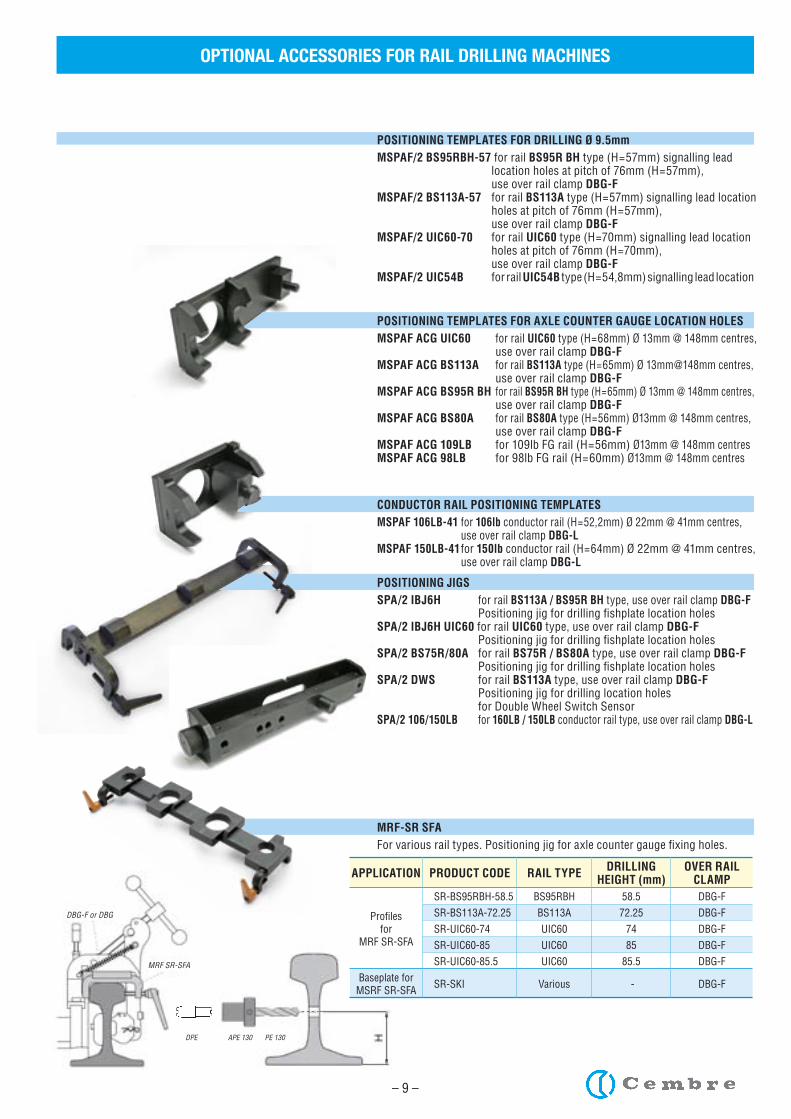
POSITIONING TEMPLATES FOR DRILLING Ø 9.5mmMSPAF/2 BS95RBH-57 for rail BS95R BH type (H=57mm) signalling lead location holes at pitch of 76mm (H=57mm), use over rail clamp DBG-FMSPAF/2 BS113A-57 for rail BS113A type (H=57mm) signalling lead location holes at pitch of 76mm (H=57mm), use over rail clamp DBG-FMSPAF/2 UIC60-70 for rail UIC60 type (H=70mm) signalling lead location holes at pitch of 76mm (H=70mm), use over rail clamp DBG-FMSPAF/2 UIC54B for rail UIC54B type (H=54,8mm) signalling lead location
POSITIONING TEMPLATES FOR AXLE COUNTER GAUGE LOCATION HOLESMSPAF ACG UIC60 for rail UIC60 type (H=68mm) Ø 13mm @ 148mm centres, use over rail clamp DBG-FMSPAF ACG BS113A for rail BS113A type (H=65mm) Ø 13mm@148mm centres, use over rail clamp DBG-F MSPAF ACG BS95R BH for rail BS95R BH type (H=65mm) Ø 13mm @ 148mm centres, use over rail clamp DBG-FMSPAF ACG BS80A for rail BS80A type (H=56mm) Ø13mm @ 148mm centres, use over rail clamp DBG-FMSPAF ACG 109LB for 109lb FG rail (H=56mm) Ø13mm @ 148mm centresMSPAF ACG 98LB for 98lb FG rail (H=60mm) Ø13mm @ 148mm centres
CONDUCTOR RAIL POSITIONING TEMPLATES MSPAF 106LB-41 for 106lb conductor rail (H=52,2mm) Ø 22mm @ 41mm centres, use over rail clamp DBG-LMSPAF 150LB-41 for 150lb conductor rail (H=64mm) Ø 22mm @ 41mm centres, use over rail clamp DBG-L
POSITIONING JIGS SPA/2 IBJ6H for rail BS113A / BS95R BH type, use over rail clamp DBG-F Positioning jig for drilling fishplate location holesSPA/2 IBJ6H UIC60 for rail UIC60 type, use over rail clamp DBG-F Positioning jig for drilling fishplate location holesSPA/2 BS75R/80A for rail BS75R / BS80A type, use over rail clamp DBG-F Positioning jig for drilling fishplate location holesSPA/2 DWS for rail BS113A type, use over rail clamp DBG-F Positioning jig for drilling location holes for Double Wheel Switch SensorSPA/2 106/150LB for 160LB / 150LB conductor rail type, use over rail clamp DBG-L
MRF-SR SFAFor various rail types. Positioning jig for axle counter gauge fixing holes.
APPLICATION PRODUCT CODE RAIL TYPE DRILLINGHEIGHT (mm)
OVER RAIL CLAMP
Profilesfor
MRF SR-SFA
SR-BS95RBH-58.5 BS95RBH 58.5 DBG-F
SR-BS113A-72.25 BS113A 72.25 DBG-F
SR-UIC60-74 UIC60 74 DBG-F
SR-UIC60-85 UIC60 85 DBG-F
SR-UIC60-85.5 UIC60 85.5 DBG-F
Baseplate forMSRF SR-SFA SR-SKI Various - DBG-F
– 10 –
BROACH CUTTERS
OPTIONAL ACCESSORIES FOR RAIL DRILLING MACHINES
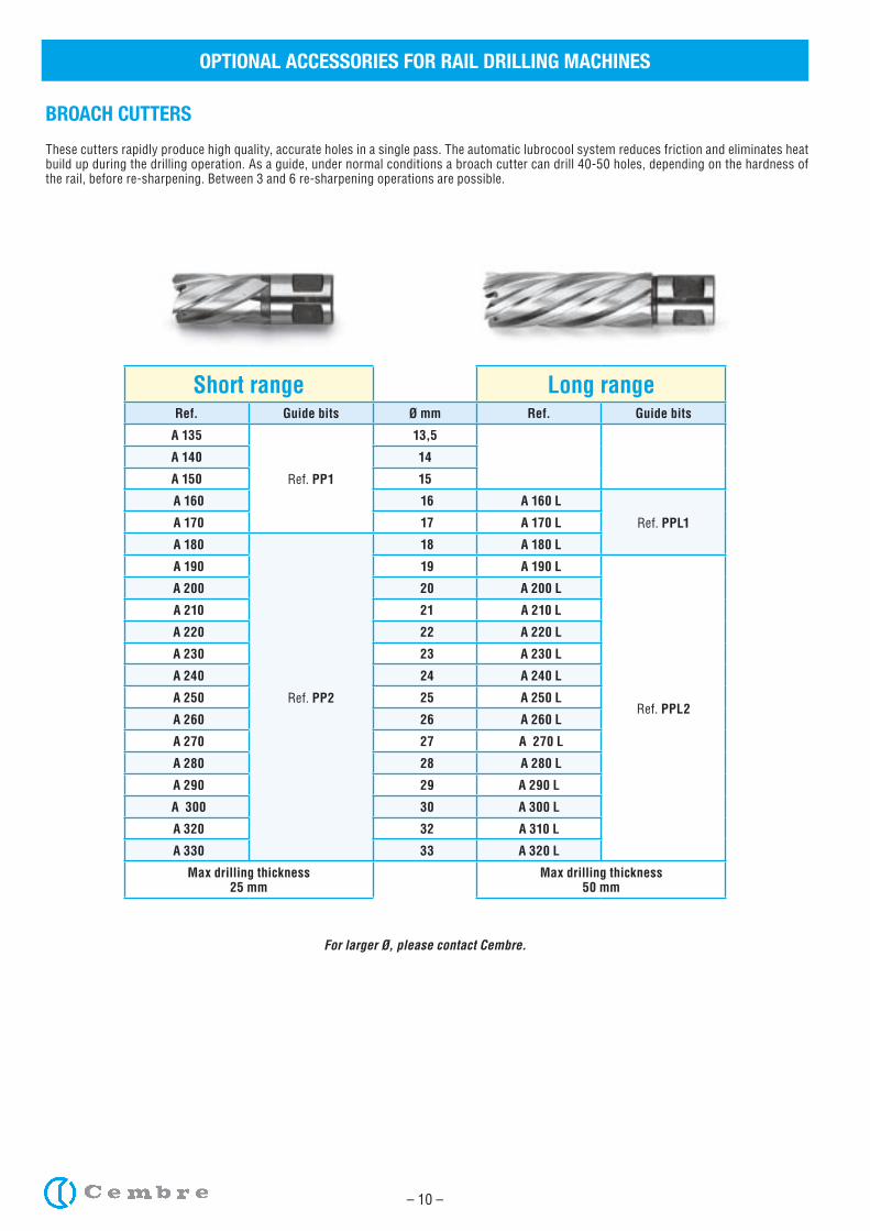
These cutters rapidly produce high quality, accurate holes in a single pass. The automatic lubrocool system reduces friction and eliminates heat build up during the drilling operation. As a guide, under normal conditions a broach cutter can drill 40-50 holes, depending on the hardness of the rail, before re-sharpening. Between 3 and 6 re-sharpening operations are possible.
Short range Long rangeRef. Guide bits Ø mm Ref. Guide bits
A 135
Ref. PP1
13,5
A 140 14
A 150 15
A 160 16 A 160 L
Ref. PPL1 A 170 17 A 170 L
A 180
Ref. PP2
18 A 180 L
A 190 19 A 190 L
Ref. PPL2
A 200 20 A 200 L
A 210 21 A 210 L
A 220 22 A 220 L
A 230 23 A 230 L
A 240 24 A 240 L
A 250 25 A 250 L
A 260 26 A 260 L
A 270 27 A 270 L
A 280 28 A 280 L
A 290 29 A 290 L
A 300 30 A 300 L
A 320 32 A 310 L
A 330 33 A 320 L
Max drilling thickness25 mm
Max drilling thickness50 mm
For larger Ø, please contact Cembre.
– 11 –
OPTIONAL ACCESSORIES FOR RAIL DRILLING MACHINES
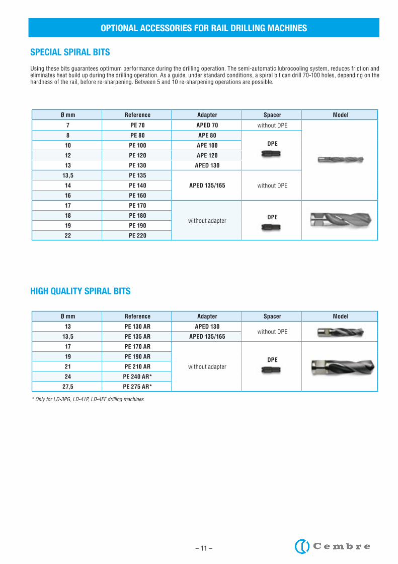
SPECIAL SPIRAL BITS
Using these bits guarantees optimum performance during the drilling operation. The semi-automatic lubrocooling system, reduces friction and eliminates heat build up during the drilling operation. As a guide, under standard conditions, a spiral bit can drill 70-100 holes, depending on the hardness of the rail, before re-sharpening. Between 5 and 10 re-sharpening operations are possible.
Ø mm Reference Adapter Spacer Model
7 PE 70 APED 70 without DPE
8 PE 80 APE 80DPE10 PE 100 APE 100
12 PE 120 APE 120
13 PE 130 APED 130
13,5 PE 135
APED 135/165 without DPE14 PE 140
16 PE 160
17 PE 170
without adapter DPE18 PE 180
19 PE 190
22 PE 220
Ø mm Reference Adapter Spacer Model
13 PE 130 AR APED 130without DPE
13,5 PE 135 AR APED 135/165
17 PE 170 AR
without adapterDPE19 PE 190 AR
21 PE 210 AR
24 PE 240 AR*
27,5 PE 275 AR*
HIGH QUALITY SPIRAL BITS
* Only for LD-3PG, LD-41P, LD-4EF drilling machines
– 12 –
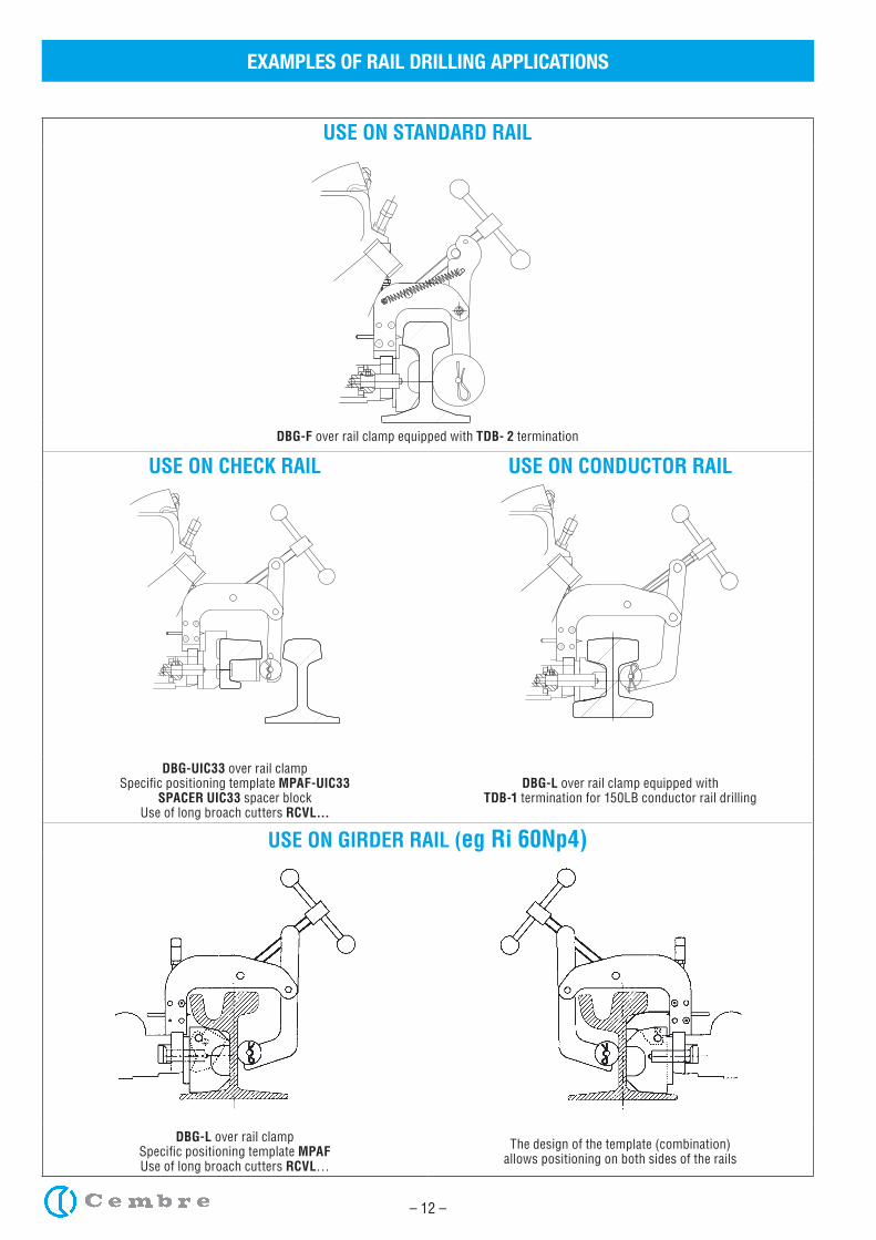
EXAMPLES OF RAIL DRILLING APPLICATIONS
USE ON STANDARD RAIL
DBG-F over rail clamp equipped with TDB- 2 termination
USE ON CHECK RAIL USE ON CONDUCTOR RAIL
DBG-UIC33 over rail clamp Specific positioning template MPAF-UIC33
SPACER UIC33 spacer blockUse of long broach cutters RCVL...
DBG-L over rail clamp equipped with TDB-1 termination for 150LB conductor rail drilling
USE ON GIRDER RAIL (eg Ri 60Np4)
DBG-L over rail clampSpecific positioning template MPAFUse of long broach cutters RCVL…
The design of the template (combination)allows positioning on both sides of the rails
– 13 –
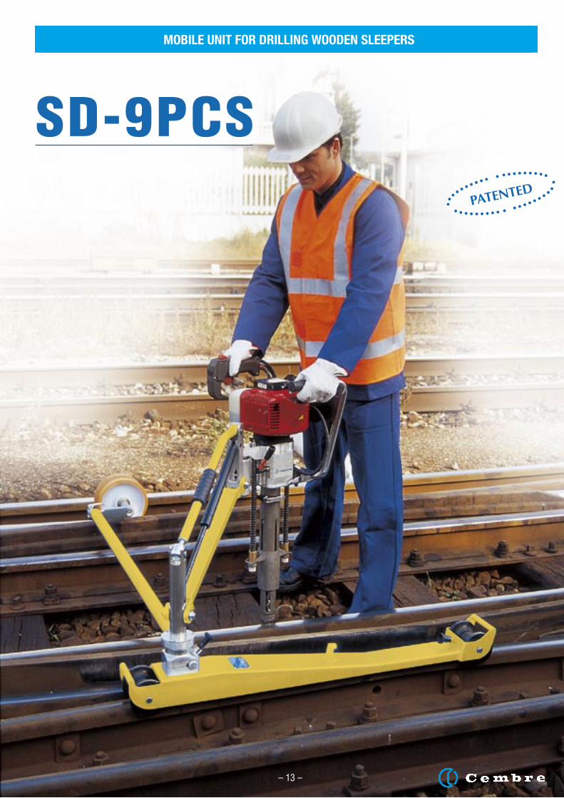
SD-9PCS
MOBILE UNIT FOR DRILLING WOODEN SLEEPERS
– 13 –
MOBILE UNIT FOR DRILLING WOODEN SLEEPERS
– 14 –
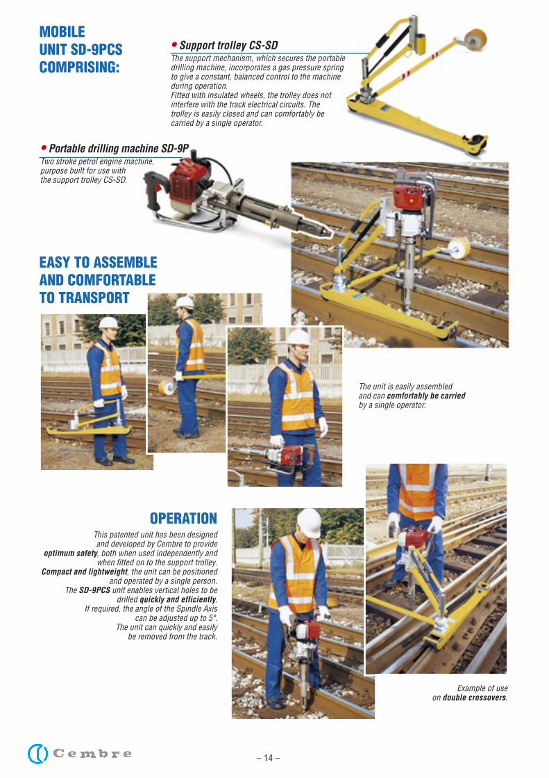
MOBILEUNIT SD-9PCSCOMPRISING:
OPERATIONThis patented unit has been designedand developed by Cembre to provide
optimum safety, both when used independently and when fitted on to the support trolley.
Compact and lightweight, the unit can be positioned and operated by a single person.
The SD-9PCS unit enables vertical holes to be drilled quickly and efficiently.
If required, the angle of the Spindle Axiscan be adjusted up to 5°.
The unit can quickly and easilybe removed from the track.
• Portable drilling machine SD-9PTwo stroke petrol engine machine,purpose built for use withthe support trolley CS-SD.
• Support trolley CS-SDThe support mechanism, which secures the portable drilling machine, incorporates a gas pressure spring to give a constant, balanced control to the machineduring operation.Fitted with insulated wheels, the trolley does not interfere with the track electrical circuits. The trolley is easily closed and can comfortably be carried by a single operator.
EASY TO ASSEMBLE AND COMFORTABLE TO TRANSPORT
The unit is easily assembledand can comfortably be carriedby a single operator.
Example of useon double crossovers.
(See Page 27)
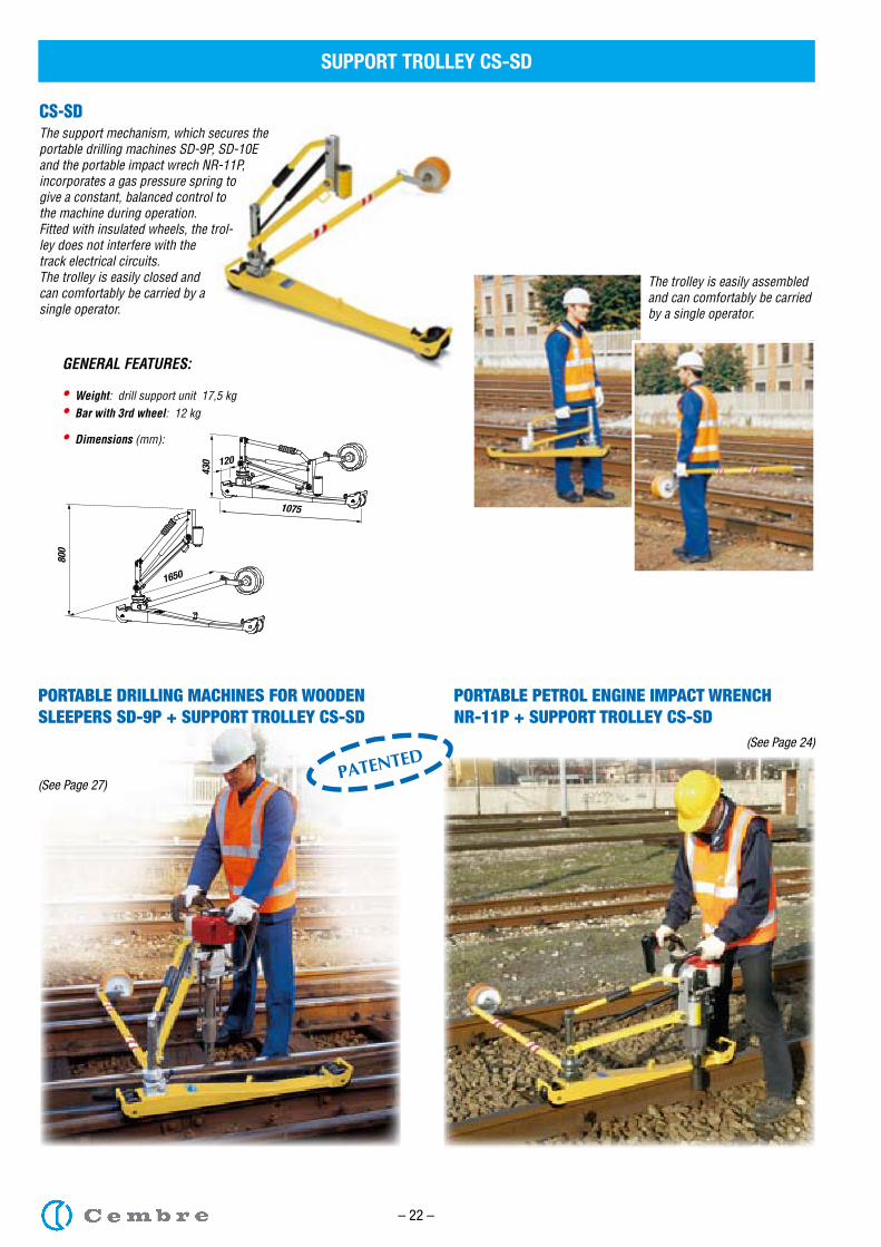
CS-SDThe support mechanism, which secures the portable drilling machines SD-9P, SD-10E and the portable impact wrech NR-11P, incorporates a gas pressure spring to give a constant, balanced control to the machine during operation.Fitted with insulated wheels, the trol-ley does not interfere with the track electrical circuits. The trolley is easily closed and can comfortably be carried by a single operator.
The trolley is easily assembledand can comfortably be carried by a single operator.
PATENTED
SUPPORT TROLLEY CS-SD
– 22 –
PORTABLE DRILLING MACHINES FOR WOODEN SLEEPERS SD-9P + SUPPORT TROLLEY CS-SD
800
1650
120
430
1075
(See Page 24)
PORTABLE PETROL ENGINE IMPACT WRENCH NR-11P + SUPPORT TROLLEY CS-SD
GENERAL FEATURES:
• Weight: drill support unit 17,5 kg• Bar with 3rd wheel: 12 kg
• Dimensions (mm):
– 23 –
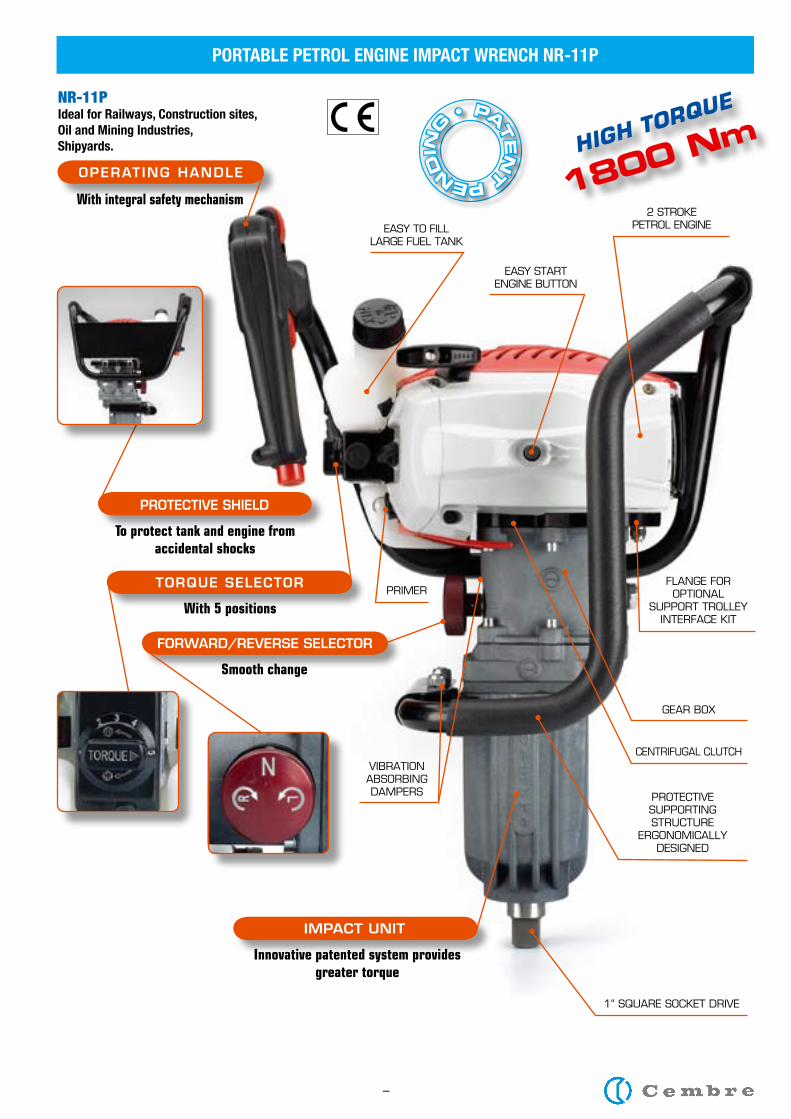
FORWARD/REVERSE SELECTOR
TORQUE SELECTOR
Smooth change
With 5 positions
PROTECTIVE SHIELD
To protect tank and engine from accidental shocks
ImPACT UnIT
Innovative patented system provides greater torque
1“ SQUARE SOCKET DRIVE
PROTECTIVE SUPPORTING STRUCTURE
ERGONOMICALLYDESIGNED
EASY TO fILL LARGE fUEL TANK
CENTRIfUGAL CLUTCH
GEAR BOX
fLANGE fOR OPTIONAL
SUPPORT TROLLEY INTERfACE KIT
PRIMER
2 STROKE PETROL ENGINE
EASY STARTENGINE BUTTON
VIBRATION ABSORBING DAMPERS
NR-11PIdeal for Railways, Construction sites,Oil and Mining Industries,Shipyards.
PORTABLE PETROL ENGINE IMPACT WRENCH NR-11P
–
PATEN
T PENDIN
G
•
HIGH TORQUE
1800 NmOPERATInG HAnDLE
With integral safety mechanism
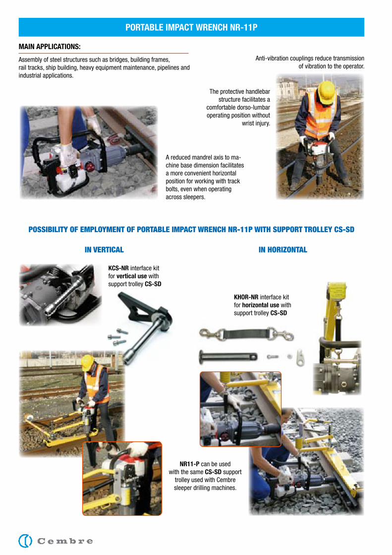
MAIN APPLICATIONS:
Assembly of steel structures such as bridges, building frames, rail tracks, ship building, heavy equipment maintenance, pipelines and industrial applications.
NR11-P can be used with the same CS-SD support
trolley used with Cembre sleeper drilling machines.
The protective handlebar structure facilitates a
comfortable dorso-lumbar operating position without
wrist injury.
Anti-vibration couplings reduce transmission of vibration to the operator.
A reduced mandrel axis to ma-chine base dimension facilitates a more convenient horizontal position for working with track bolts, even when operating across sleepers.
KCS-NR interface kit for vertical use with support trolley CS-SD
PORTABLE IMPACT WRENCH NR-11P
KHOR-NR interface kit for horizontal use with support trolley CS-SD
IN hoRIzoNtal IN VERtICal
PoSSIBIlItY oF EMPloYMENt oF PoRtaBlE IMPaCt WRENCh NR-11P WIth SUPPoRt tRollEY CS-SD
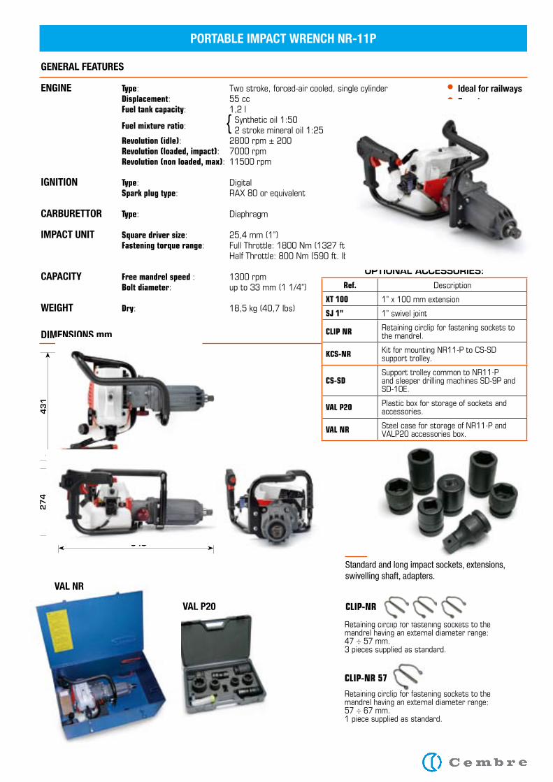
Standard and long impact sockets, extensions, swivelling shaft, adapters.
• Ideal for railways• Easy to carry• Easy to use
VAL NR
VAL P20
DIMENSIONS mm
PORTABLE IMPACT WRENCH NR-11P
GENERAL FEATURES
ENGINE Type: Twostroke,forced-aircooled,singlecylinder Displacement: 55cc Fuel tank capacity: 1,2l
Fuel mixture ratio:Syntheticoil1:50
2strokemineraloil1:25 Revolution (idle): 2800rpm±200 Revolution (loaded, impact): 7000rpm Revolution (non loaded, max):11500rpm
IGNITION Type: Digital Spark plug type: RAX80orequivalent
CARBURETTOR Type: Diaphragm
IMPACT UNIT Square driver size: 25,4mm(1”) Fastening torque range: FullThrottle:1800Nm(1327ft.lbs) HalfThrottle:800Nm(590ft.lbs)
CAPACITY Free mandrel speed : 1300rpm Bolt diameter: upto33mm(11/4”)
WEIGHT Dry: 18,5kg(40,7lbs)
{
OPTIOnAL ACCESSORIES:Ref. Description
XT 100 1”x100mmextension
SJ 1” 1”swiveljoint
CLIP NR Retainingcirclipforfasteningsocketstothemandrel.
KCS-NR KitformountingNR11-PtoCS-SDsupporttrolley.
CS-SDSupporttrolleycommontoNR11-PandsleeperdrillingmachinesSD-9PandSD-10E.
VAL P20 Plasticboxforstorageofsocketsandaccessories.
VAL NR SteelcaseforstorageofNR11-PandVALP20accessoriesbox.
640
27
44
31
CLIP-NR 57
Retainingcirclipforfasteningsocketstothemandrelhavinganexternaldiameterrange:47÷57mm.3piecessuppliedasstandard.
Retainingcirclipforfasteningsocketstothemandrelhavinganexternaldiameterrange:57÷67mm.1piecesuppliedasstandard.
CLIP-NR
– 15 –
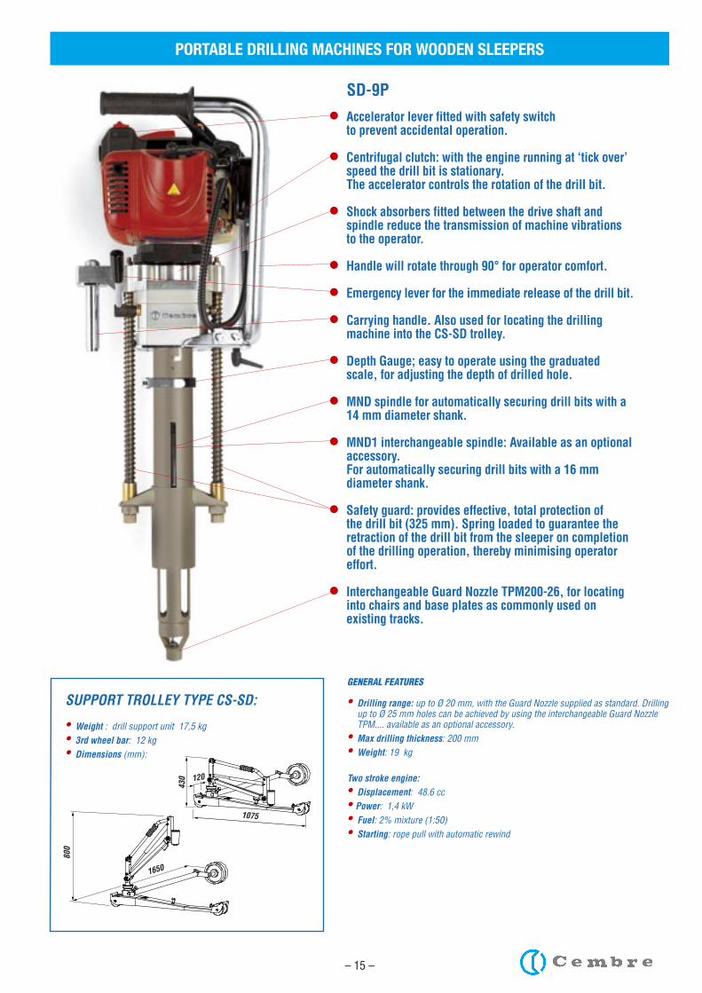
• Accelerator lever fitted with safety switch to prevent accidental operation.
• Centrifugal clutch: with the engine running at ‘tick over’ speed the drill bit is stationary.
The accelerator controls the rotation of the drill bit.
• Shock absorbers fitted between the drive shaft and spindle reduce the transmission of machine vibrations
to the operator.
• Handle will rotate through 90° for operator comfort.
• Emergency lever for the immediate release of the drill bit.
• Carrying handle. Also used for locating the drilling machine into the CS-SD trolley.
• Depth Gauge; easy to operate using the graduated scale, for adjusting the depth of drilled hole.
• MND spindle for automatically securing drill bits with a 14 mm diameter shank.
• MND1 interchangeable spindle: Available as an optional accessory.
For automatically securing drill bits with a 16 mm diameter shank.
• Safety guard: provides effective, total protection of the drill bit (325 mm). Spring loaded to guarantee the retraction of the drill bit from the sleeper on completion of the drilling operation, thereby minimising operator effort.
• Interchangeable Guard Nozzle TPM200-26, for locating into chairs and base plates as commonly used on existing tracks.
SD-9P
GENERAL FEATURES
• Drilling range: up to Ø 20 mm, with the Guard Nozzle supplied as standard. Drilling up to Ø 25 mm holes can be achieved by using the interchangeable Guard Nozzle TPM.... available as an optional accessory.
• Max drilling thickness: 200 mm• Weight: 19 kg
Two stroke engine:• Displacement: 48.6 cc• Power: 1,4 kW• Fuel: 2% mixture (1:50)• Starting: rope pull with automatic rewind
SUPPORT TROLLEY TYPE CS-SD:
• Weight : drill support unit 17,5 kg• 3rd wheel bar: 12 kg• Dimensions (mm):
800
1650
120
430
1075
PORTABLE DRILLING MACHINES FOR WOODEN SLEEPERS
– 16 –
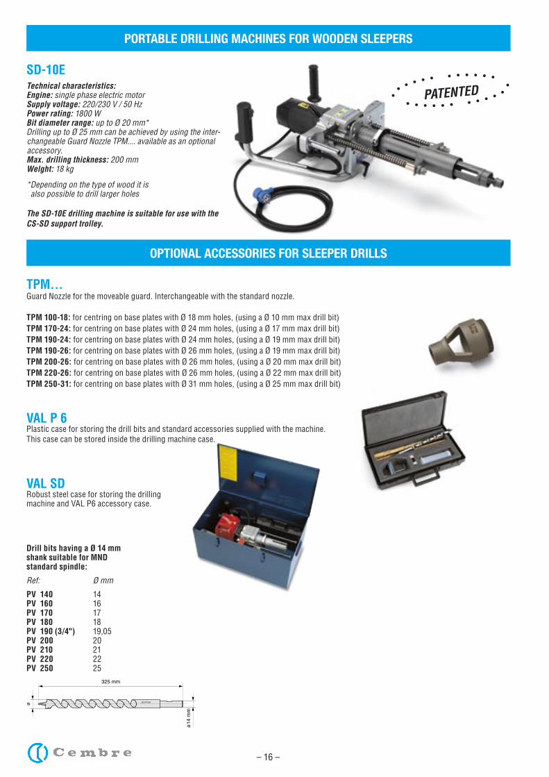
TPM...Guard Nozzle for the moveable guard. Interchangeable with the standard nozzle.
TPM 100-18: for centring on base plates with Ø 18 mm holes, (using a Ø 10 mm max drill bit)TPM 170-24: for centring on base plates with Ø 24 mm holes, (using a Ø 17 mm max drill bit)TPM 190-24: for centring on base plates with Ø 24 mm holes, (using a Ø 19 mm max drill bit)TPM 190-26: for centring on base plates with Ø 26 mm holes, (using a Ø 19 mm max drill bit)TPM 200-26: for centring on base plates with Ø 26 mm holes, (using a Ø 20 mm max drill bit)TPM 220-26: for centring on base plates with Ø 26 mm holes, (using a Ø 22 mm max drill bit)TPM 250-31: for centring on base plates with Ø 31 mm holes, (using a Ø 25 mm max drill bit)
VAL P 6Plastic case for storing the drill bits and standard accessories supplied with the machine. This case can be stored inside the drilling machine case.
VAL SDRobust steel case for storing the drillingmachine and VAL P6 accessory case.
Drill bits having a Ø 14 mmshank suitable for MND standard spindle:
Ref: Ø mm
PV 140 14PV 160 16PV 170 17PV 180 18PV 190 (3/4") 19,05PV 200 20PV 210 21PV 220 22PV 250 25
PV160
325 mm
ø
ø14
mm
OPTIONAL ACCESSORIES FOR SLEEPER DRILLS
PORTABLE DRILLING MACHINES FOR WOODEN SLEEPERS
SD-10ETechnical characteristics:Engine: single phase electric motorSupply voltage: 220/230 V / 50 HzPower rating: 1800 WBit diameter range: up to Ø 20 mm*Drilling up to Ø 25 mm can be achieved by using the inter-changeable Guard Nozzle TPM.... available as an optional accessory.Max. drilling thickness: 200 mmWelght: 18 kg *Depending on the type of wood it is also possible to drill larger holes
The SD-10E drilling machine is suitable for use with the CS-SD support trolley.
PATENTED
– 17 –
PORTABLE DRILLING MACHINES FOR WOODEN SLEEPERS
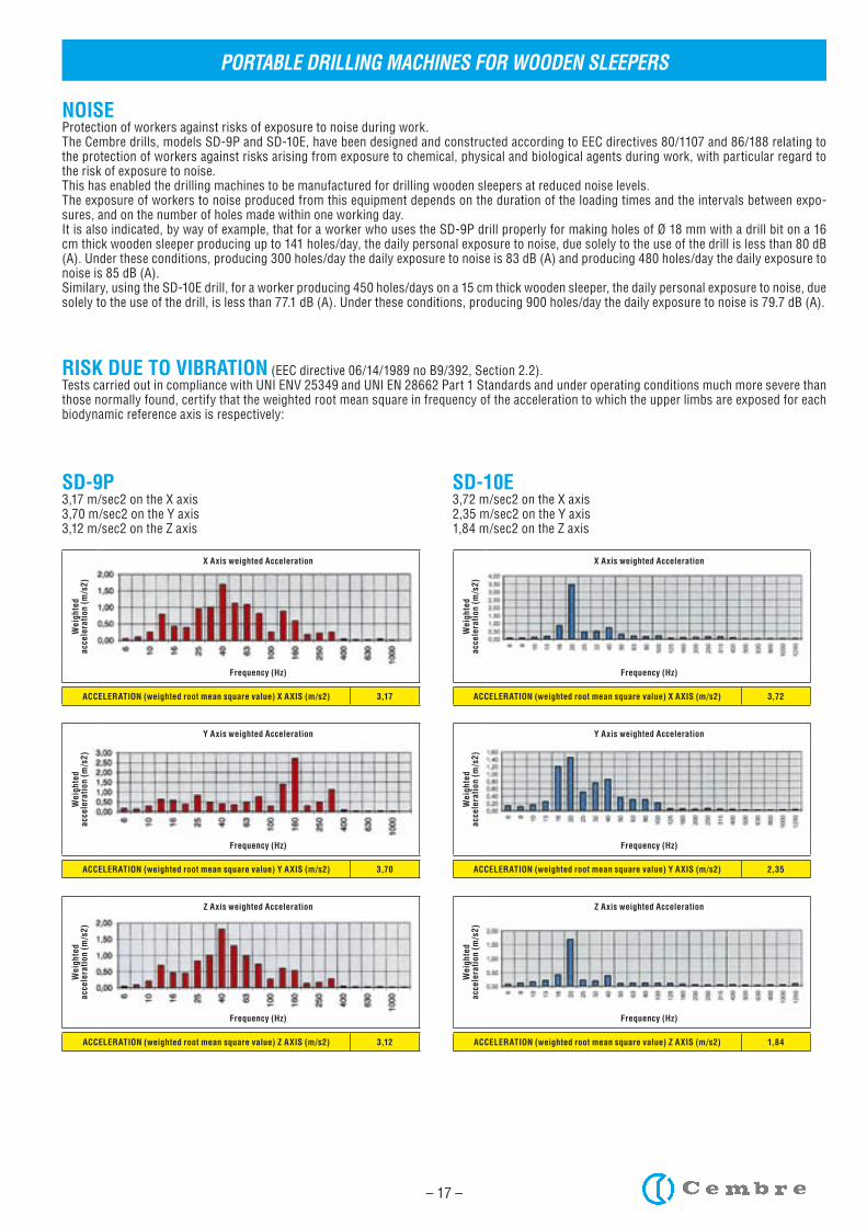
NOISEProtection of workers against risks of exposure to noise during work.The Cembre drills, models SD-9P and SD-10E, have been designed and constructed according to EEC directives 80/1107 and 86/188 relating to the protection of workers against risks arising from exposure to chemical, physical and biological agents during work, with particular regard to the risk of exposure to noise.This has enabled the drilling machines to be manufactured for drilling wooden sleepers at reduced noise levels.The exposure of workers to noise produced from this equipment depends on the duration of the loading times and the intervals between expo-sures, and on the number of holes made within one working day.It is also indicated, by way of example, that for a worker who uses the SD-9P drill properly for making holes of Ø 18 mm with a drill bit on a 16 cm thick wooden sleeper producing up to 141 holes/day, the daily personal exposure to noise, due solely to the use of the drill is less than 80 dB (A). Under these conditions, producing 300 holes/day the daily exposure to noise is 83 dB (A) and producing 480 holes/day the daily exposure to noise is 85 dB (A).Similary, using the SD-10E drill, for a worker producing 450 holes/days on a 15 cm thick wooden sleeper, the daily personal exposure to noise, due solely to the use of the drill, is less than 77.1 dB (A). Under these conditions, producing 900 holes/day the daily exposure to noise is 79.7 dB (A).
RISK DUE TO VIBRATION (EEC directive 06/14/1989 no B9/392, Section 2.2).Tests carried out in compliance with UNI ENV 25349 and UNI EN 28662 Part 1 Standards and under operating conditions much more severe than those normally found, certify that the weighted root mean square in frequency of the acceleration to which the upper limbs are exposed for each biodynamic reference axis is respectively:
SD-9P3,17 m/sec2 on the X axis3,70 m/sec2 on the Y axis3,12 m/sec2 on the Z axis
SD-10E3,72 m/sec2 on the X axis2,35 m/sec2 on the Y axis1,84 m/sec2 on the Z axis
Wei
ghte
dac
cele
rati
on (
m/s
2)
X Axis weighted Acceleration
Frequency (Hz)
ACCELERATION (weighted root mean square value) X AXIS (m/s2) 3,17
Wei
ghte
dac
cele
rati
on (
m/s
2)
Y Axis weighted Acceleration
Frequency (Hz)
ACCELERATION (weighted root mean square value) Y AXIS (m/s2) 3,70
Wei
ghte
dac
cele
rati
on (
m/s
2)
Z Axis weighted Acceleration
Frequency (Hz)
ACCELERATION (weighted root mean square value) Z AXIS (m/s2) 3,12
Wei
ghte
dac
cele
rati
on (
m/s
2)
X Axis weighted Acceleration
Frequency (Hz)
ACCELERATION (weighted root mean square value) X AXIS (m/s2) 3,72
Wei
ghte
dac
cele
rati
on (
m/s
2)
Y Axis weighted Acceleration
Frequency (Hz)
ACCELERATION (weighted root mean square value) Y AXIS (m/s2) 2,35
Wei
ghte
dac
cele
rati
on (
m/s
2)
Z Axis weighted Acceleration
Frequency (Hz)
ACCELERATION (weighted root mean square value) Z AXIS (m/s2) 1,84
– 18 –
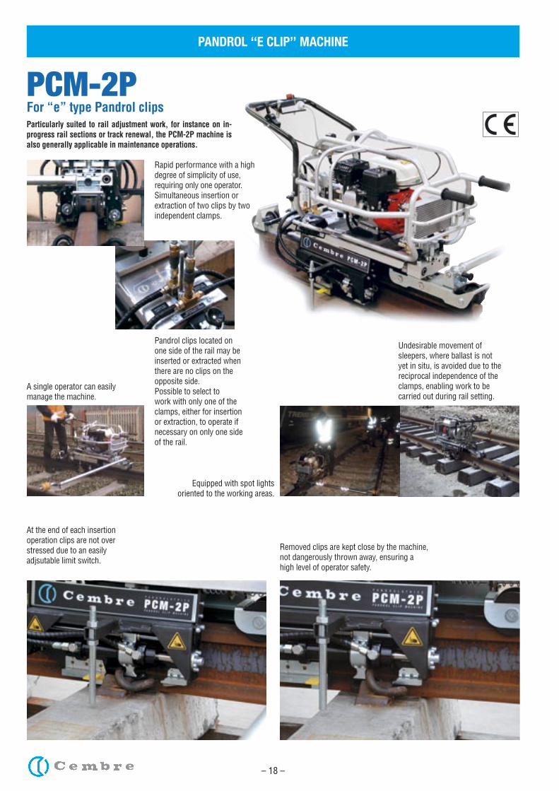
PCM-2PFor “e” type Pandrol clipsParticularly suited to rail adjustment work, for instance on in-progress rail sections or track renewal, the PCM-2P machine is also generally applicable in maintenance operations.
PANDROL ‘‘E CLIP’’ MACHINE
Pandrol clips located on one side of the rail may be inserted or extracted when there are no clips on the opposite side. Possible to select to work with only one of the clamps, either for insertion or extraction, to operate if necessary on only one side of the rail.
Rapid performance with a high degree of simplicity of use, requiring only one operator. Simultaneous insertion or extraction of two clips by two independent clamps.
Removed clips are kept close by the machine, not dangerously thrown away, ensuring ahigh level of operator safety.
At the end of each insertion operation clips are not over stressed due to an easily adjsutable limit switch.
Undesirable movement of sleepers, where ballast is not yet in situ, is avoided due to the reciprocal independence of the clamps, enabling work to be carried out during rail setting.
Equipped with spot lightsoriented to the working areas.
A single operator can easily manage the machine.
– 19 –
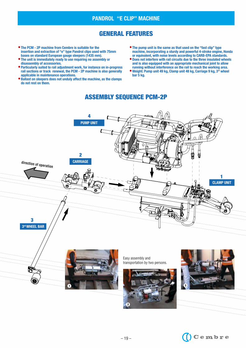
PUMP UNIT
CLAMP UNIT
CARRIAGE
3rd WHEEL BAR
• The PCM - 2P machine from Cembre is suitable for the insertion and extraction of “e” type Pandrol clips used with 75mm
bases on standard European gauge sleepers (1435 mm).• The unit is immediately ready to use requiring no assembly or
disassembly of accessories.• Particularly suited to rail adjustment work, for instance on in-progress
rail sections or track renewal, the PCM - 2P machine is also generally applicable in maintenance operations.
• Ballast on sleepers does not unduly affect the machine, as the clamps do not rest on them.
• The pump unit is the same as that used on the “fast clip” type machine, incorporating a sturdy and powerful 4-stroke engine, Honda or equivalent, with noise levels according to CARB-EPA standards.
• Does not interfere with rail circuits due to the three insulated wheels and is also equipped with an appropriate mechanical joint to allow running without interference on the rail to reach the working area.
• Weight: Pump unit 49 kg, Clamp unit 48 kg, Carriage 9 kg, 3rd wheel bar 5 kg.
GENERAL FEATURES
ASSEMBLY SEQUENCE PCM-2P
4
2
3
1
direction of operation
Easy assembly and transportation by two persons.
1
2
3
PANDROL ‘‘E CLIP’’ MACHINE
– 20 –
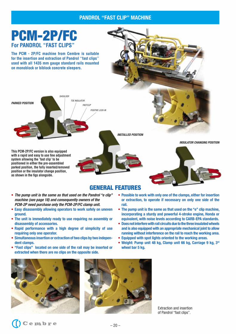
PCM-2P/FCFor PANDROL “FAST CLIPS”
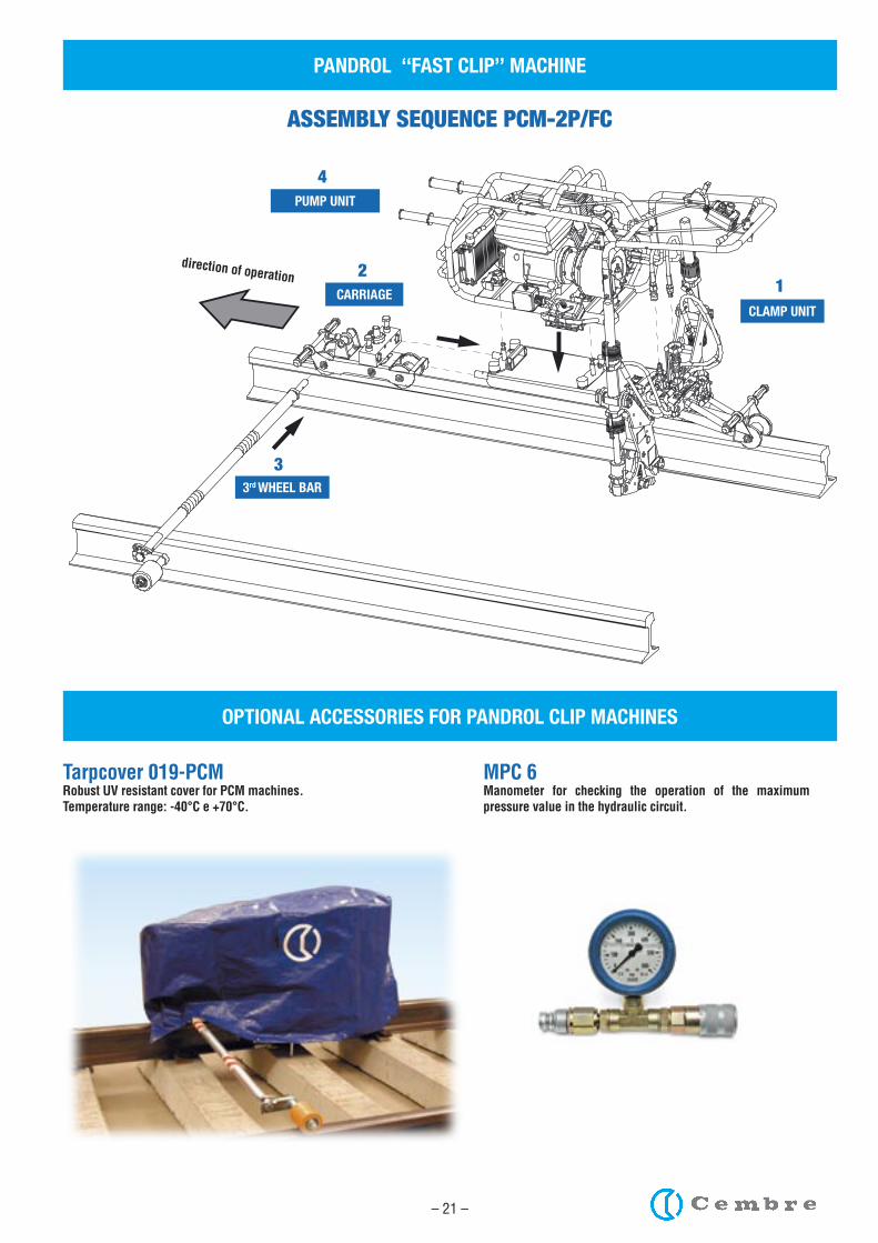
PANDROL ‘‘FAST CLIP’’ MACHINE
The PCM - 2P/FC machine from Cembre is suitable for the insertion and extraction of Pandrol ‘‘fast clips’’ used with all 1435 mm gauge standard rails mounted on monoblock or biblock concrete sleepers.
• The pump unit is the same as that used on the Pandrol ‘‘e clip’’ machine (see page 18) and consequently owners of the
PCM-2P need purchase only the PCM-2P/FC clamp unit.• Easy disassembly allowing operators to work safely on uneven
ground.• The unit is immediately ready to use requiring no assembly or
disassembly of accessories.• Rapid performance with a high degree of simplicity of use
requiring only one operator. • Simultaneous insertion or extraction of two clips by two indepen-
dent clamps.• ‘‘Fast clips’’ located on one side of the rail may be inserted or
extracted when there are no clips on the opposite side.
• Possible to work with only one of the clamps, either for insertion or extraction, to operate if necessary on only one side of the rail.
• The pump unit is the same as that used on the ‘‘e’’ clip machine, incorporating a sturdy and powerful 4-stroke engine, Honda or equivalent, with noise levels according to CARB-EPA standards.
• Does not interfere with rail circuits due to the three insulated wheels and is also equipped with an appropriate mechanical joint to allow running without interference on the rail to reach the working area.
• Equipped with spot lights oriented to the working areas.• Weight: Pump unit 48 kg, Clamp unit 66 kg, Carriage 9 kg, 3rd
wheel bar 5 kg.
GENERAL FEATURES
PARKED POSITION
INSTALLED POSITION
Extraction and insertionof Pandrol ‘‘fast clips’’.
This PCM-2P/FC version is also equipped with a rapid and easy to use fine adjustment system allowing the ‘fast clip’ to be positioned in either the pre-assembled parked position, the fully inserted/removed position or the insulator change position,as shown in the figs alongside.
SHOULDER
TOE INSULATOR
FASTCLIP
POSITIVE LOCK-IN
INSULATOR CHANGING POSITION
– 21 –
PANDROL ‘‘FAST CLIP’’ MACHINE
OPTIONAL ACCESSORIES FOR PANDROL CLIP MACHINES
Tarpcover 019-PCMRobust UV resistant cover for PCM machines.Temperature range: -40°C e +70°C.
MPC 6Manometer for checking the operation of the maximum pressure value in the hydraulic circuit.
PUMP UNIT
CLAMP UNITCARRIAGE
ASSEMBLY SEQUENCE PCM-2P/FC
direction of operation 2
4
1
3rd WHEEL BAR
3
– 24 –
orthogonal cut
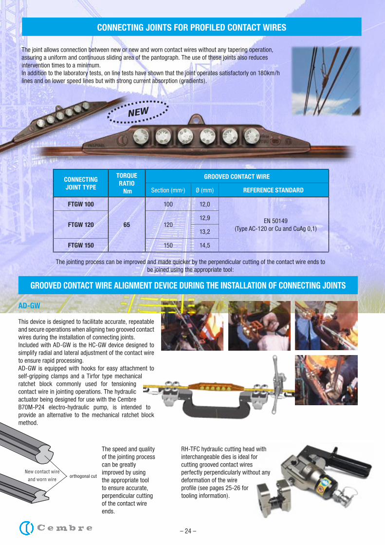
NEW
CONNECTING JOINTS FOR PROFILED CONTACT WIRES
The joint allows connection between new or new and worn contact wires without any tapering operation, assuring a uniform and continuous sliding area of the pantograph. The use of these joints also reduces intervention times to a minimum.In addition to the laboratory tests, on line tests have shown that the joint operates satisfactorly on 180km/h lines and on lower speed lines but with strong current absorption (gradients).
CONNECTING JOINT TYPE
TORQUE RATIO Nm
GROOVED CONTACT WIRE
Section (mm2) Ø (mm) REFERENCE STANDARD
FTGW 100
65
100 12,0
EN 50149 (Type AC-120 or Cu and CuAg 0,1)
FTGW 120 12012,9
13,2
FTGW 150 150 14,5
The jointing process can be improved and made quicker by the perpendicular cutting of the contact wire ends to be joined using the appropriate tool:
RH-TFC hydraulic cutting head with interchangeable dies is ideal for cutting grooved contact wires perfectly perpendicularly without any deformation of the wire profile (see pages 25-26 for tooling information).
The speed and quality of the jointing process can be greatly improved by using the appropriate tool to ensure accurate, perpendicular cutting of the contact wire ends.
AD-GW
This device is designed to facilitate accurate, repeatable and secure operations when aligning two grooved contact wires during the installation of connecting joints.Included with AD-GW is the HC-GW device designed to simplify radial and lateral adjustment of the contact wire to ensure rapid processing.AD-GW is equipped with hooks for easy attachment to self-gripping clamps and a Tirfor type mechanical ratchet block commonly used for tensioning contact wire in jointing operations. The hydraulic actuator being designed for use with the Cembre B70M-P24 electro-hydraulic pump, is intended to provide an alternative to the mechanical ratchet block method.
GROOVED CONTACT WIRE ALIGNMENT DEVICE DURING THE INSTALLATION OF CONNECTING JOINTS
New contact wire
and worn wire
– 25 –
MFC-AC107 die set to use with RH-TFC head to cut contact wires in accordance with BS23:1970 standard (100sqmm size, Ø 11,8mm). MFC-AC120 die set to use with RH-TFC head to cut contact wires in accordance with UNEL 70611- 71 standard (120mm2 size, Ø 12,9mm) and with EN50149 standard (120mm2, Ø 13,2mm).
DIE SETS
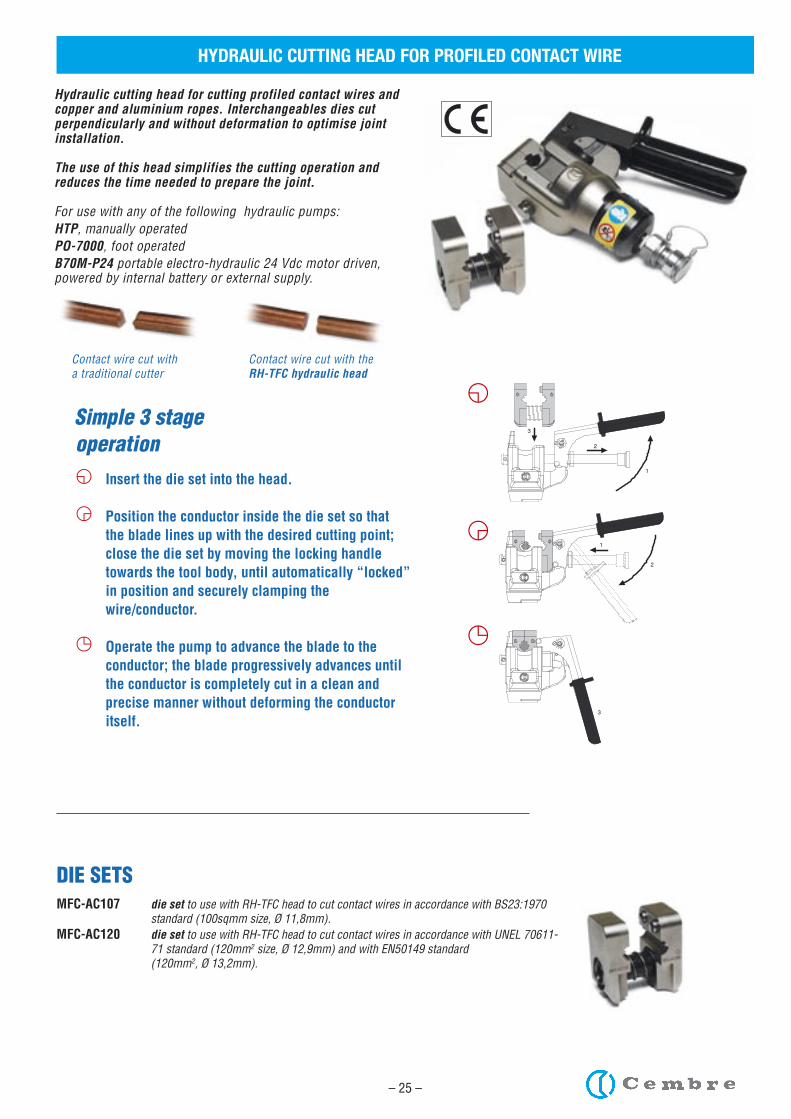
Contact wire cut with a traditional cutter
Contact wire cut with the RH-TFC hydraulic head
Hydraulic cutting head for cutting profiled contact wires and copper and aluminium ropes. Interchangeables dies cut perpendicularly and without deformation to optimise joint installation.
The use of this head simplifies the cutting operation and reduces the time needed to prepare the joint.
For use with any of the following hydraulic pumps:HTP, manually operatedPO-7000, foot operatedB70M-P24 portable electro-hydraulic 24 Vdc motor driven, powered by internal battery or external supply.
HYDRAULIC CUTTING HEAD FOR PROFILED CONTACT WIRE
カ Insert the die set into the head.
キ Position the conductor inside the die set so that the blade lines up with the desired cutting point; close the die set by moving the locking handle towards the tool body, until automatically “locked” in position and securely clamping the wire/conductor.
ク Operate the pump to advance the blade to the conductor; the blade progressively advances until the conductor is completely cut in a clean and precise manner without deforming the conductor itself.
operation
1
2
1
2
3
3
カ
キ
ク
Simple 3 stage
– 26 –
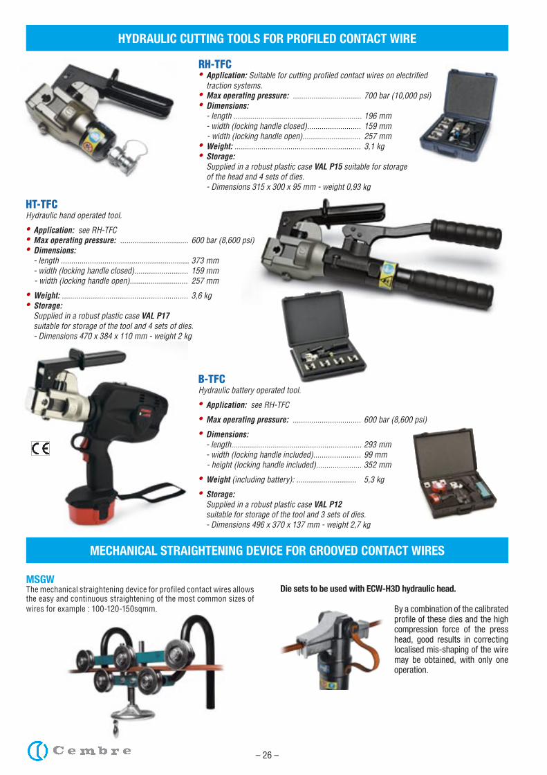
MECHANICAL STRAIGHTENING DEVICE FOR GROOVED CONTACT WIRES
MSGWThe mechanical straightening device for profiled contact wires allows the easy and continuous straightening of the most common sizes of wires for example : 100-120-150sqmm.
Die sets to be used with ECW-H3D hydraulic head.
By a combination of the calibrated profile of these dies and the high compression force of the press head, good results in correcting localised mis-shaping of the wire may be obtained, with only one operation.
HYDRAULIC CUTTING TOOLS FOR PROFILED CONTACT WIRE
HT-TFC Hydraulic hand operated tool.
• Application: see RH-TFC• Max operating pressure: ................................. 600 bar (8,600 psi)• Dimensions: - length .............................................................. 373 mm - width (locking handle closed).......................... 159 mm - width (locking handle open)............................ 257 mm
• Weight: ............................................................. 3,6 kg• Storage: Supplied in a robust plastic case VAL P17 suitable for storage of the tool and 4 sets of dies. - Dimensions 470 x 384 x 110 mm - weight 2 kg
B-TFC Hydraulic battery operated tool.
• Application: see RH-TFC
• Max operating pressure: ................................. 600 bar (8,600 psi)
• Dimensions: - length............................................................... 293 mm - width (locking handle included)....................... 99 mm - height (locking handle included)...................... 352 mm
• Weight (including battery): ............................. 5,3 kg
• Storage: Supplied in a robust plastic case VAL P12 suitable for storage of the tool and 3 sets of dies. - Dimensions 496 x 370 x 137 mm - weight 2,7 kg
RH-TFC• Application: Suitable for cutting profiled contact wires on electrified traction systems.• Max operating pressure: ................................. 700 bar (10,000 psi)• Dimensions: - length .............................................................. 196 mm - width (locking handle closed).......................... 159 mm - width (locking handle open)............................ 257 mm• Weight: ............................................................. 3,1 kg• Storage: Supplied in a robust plastic case VAL P15 suitable for storage of the head and 4 sets of dies. - Dimensions 315 x 300 x 95 mm - weight 0,93 kg
– 27 –
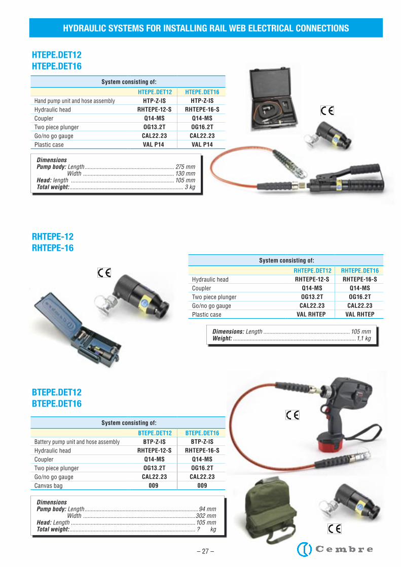
HYDRAULIC SYSTEMS FOR INSTALLING RAIL WEB ELECTRICAL CONNECTIONS
RHTEPE-12RHTEPE-16
Dimensions: Length ......................................................... 105 mmWeight: .................................................................................1,1 kg
BTEPE.DET12BTEPE.DET16
System consisting of:
BTEPE.DET12 BTEPE.DET16 Battery pump unit and hose assembly BTP-Z-IS BTP-Z-ISHydraulic head RHTEPE-12-S RHTEPE-16-SCoupler Q14-MS Q14-MSTwo piece plunger OG13.2T OG16.2TGo/no go gauge CAL22.23 CAL22.23Canvas bag 009 009
Dimensions Pump body: Length ...........................................................................94 mm Width ..........................................................................302 mmHead: Length ..................................................................................105 mmTotal weight: ................................................................................... ? kg
System consisting of:
RHTEPE.DET12 RHTEPE.DET16 Hydraulic head RHTEPE-12-S RHTEPE-16-SCoupler Q14-MS Q14-MSTwo piece plunger OG13.2T OG16.2TGo/no go gauge CAL22.23 CAL22.23Plastic case VAL RHTEP VAL RHTEP
HTEPE.DET12HTEPE.DET16
Dimensions Pump body: Length ........................................................... 275 mm Width ............................................................ 130 mmHead: length .................................................................... 105 mmTotal weight: ........................................................................... 3 kg
System consisting of:
HTEPE.DET12 HTEPE.DET16 Hand pump unit and hose assembly HTP-Z-IS HTP-Z-ISHydraulic head RHTEPE-12-S RHTEPE-16-SCoupler Q14-MS Q14-MSTwo piece plunger OG13.2T OG16.2TGo/no go gauge CAL22.23 CAL22.23Plastic case VAL P14 VAL P14
– 28 –
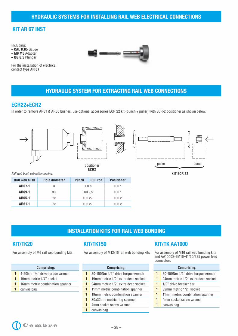
KIT/TK20For assembly of M6 rail web bonding kits
Comprising:
1 4-20Nm 1/4’’ drive torque wrench1 10mm metric 1/4’’ socket1 16mm metric combination spanner1 canvas bag
KIT/TK150For assembly of M12/16 rail web bonding kits
Comprising:
1 30-150Nm 1/2’’ drive torque wrench1 19mm metric 1/2’’ extra deep socket1 24mm metric 1/2’’ extra deep socket1 11mm metric combination spanner1 19mm metric combination spanner1 30x32mm metric ring spanner1 4mm socket screw wrench1 canvas bag
KIT/TK AA1000For assembly of M16 rail web bonding kits and AA1000S-2M16-41/50/325 power feed connectors
Comprising:
1 30-150Nm 1/2’’ drive torque wrench1 24mm metric 1/2’’ extra deep socket1 1/2’’ drive breaker bar1 32mm metric 1/2’’ socket1 11mm metric combination spanner1 4mm socket screw wrench1 canvas bag
Rail web bush Hole diameter Punch Pull rod Positioner
AR67-1 8 ECR 8 ECR 1
AR69-1 9,5 ECR 9,5 ECR 1
AR65-1 22 ECR 22 ECR 2
AR61-1 22 ECR 22 ECR 2
Rail web bush extraction tooling:
HYDRAULIC SYSTEMS FOR INSTALLING RAIL WEB ELECTRICAL CONNECTIONS
KIT AR 67 INST
Including:– CAL 8.85 Gauge– M9 M5 Adapter – OG 6.5 Plunger
For the installation of electricalcontact type AR 67
HYDRAULIC SYSTEM FOR EXTRACTING RAIL WEB CONNECTIONS
ECR22+ECR2In order to remove AR61 & AR65 bushes, use optional accessories ECR 22 kit (punch + puller) with ECR-2 positioner as shown below.
positionerECR2
KIT ECR 22
INSTALLATION KITS FOR RAIL WEB BONDING
– 29 –
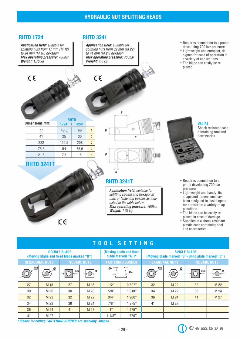
HYDRAULIC NUT SPLITTING HEADS
RHTD 1724 RHTD 3241Application field: suitable for splitting nuts from 17 mm (M 12) to 24 mm (M 16) hexagonMax operating pressure: 700barWeight: 1,76 kg
Application field: suitable for splitting nuts from 32 mm (M 22) to 41 mm (M 27) hexagonMax operating pressure: 700barWeight: 4,6 kg
Application field: suitable for splitting square and hexagonalnuts or fastening bushes as indi-cated in the table belowMax operating pressure: 700barWeight: 1,76 kg
DOUBLE BLADE(Moving blade and fixed blade marked ‘‘B’’)
(Moving blade and fixed blade marked ‘‘A’’)*
SINGLE BLADE(Moving blade marked ‘‘B’’- Blind plate marked ‘‘C’’)
HEXAGONAL NUTS SQUARE NUTS FASTENING BUSHES HEXAGONAL NUTS SQUARE NUTS
27 M 18 27 M 18 1/2’’ 0.807’’ 32 M 22 32 M 22
30 M 20 30 M 20 5/8’’ 1.010’’ 34 M 22 36 M 24
32 M 22 32 M 22 3/4’’ 1.200’’ 36 M 24 41 M 27
34 M 22 36 M 24 7/8’’ 1.375’’ 41 M 27
36 M 24 41 M 27 1’’ 1.575’’
41 M 27 1 1/8’’ 1.770’’
→
→Ø
→mmØ→mm
→
→
→
→Ø
→mmØ→mm
→
→ØB
→
→
ØA →
→
→→
T O O L S E T T I N G
→
→Ø
→mmØ→mm
→
→
→
→Ø
→mmØ→mm
→
→ØB
→
→
ØA →
→
→→ →
→Ø
→mmØ→mm
→
→
→
→Ø
→mmØ→mm
→
→ØB
→
→
ØA →
→
→→ →
→Ø
→mmØ→mm
→
→
→
→Ø
→mmØ→mm
→
→ØB
→
→
ØA →
→
→→ →
→Ø
→mmØ→mm
→
→
→
→Ø
→mmØ→mm
→
→ØB
→
→
ØA →
→
→→ →
→Ø
→mmØ→mm
→
→
→
→Ø
→mmØ→mm
→
→ØB
→
→
ØA →
→
→→ →
→Ø
→mmØ→mm
→
→
→
→Ø
→mmØ→mm
→
→ØB
→
→
ØA →
→
→→ →
→Ø
→mmØ→mm
→
→
→
→Ø
→mmØ→mm
→
→ØB
→
→
ØA →
→
→→ →
→Ø
→mmØ→mm
→
→
→
→Ø
→mmØ→mm
→
→ØB
→
→
ØA →
→
→→
*Blades for cutting FASTENING BUSHES are specially shaped
a
b
c
d
e
RHTD1724 | 3241
RHTD 3241T
RHTD 3241T
• Requires connection to a pump developing 700 bar pressure• Lightweight and compact, de signed for ease of operation in a variety of applications.• The blade can easily be re placed
• Requires connection to a pump developing 700 bar pressure.• Lightweight and handy; its shape and dimensions have been designed to assist opera tor comfort in a variety of ap plications.• The blade can be easily re placed in case of damage.• Supplied in a shock resistant plastic case containing tool and accessories.
VAL P4Shock resistant case containing tool and accessories
Dimensions mm:
77 40,5 66 a
41 25 36 b
222 150,5 208 c
75,5 54 75,5 d
21,5 7,5 16 e
– 30 –
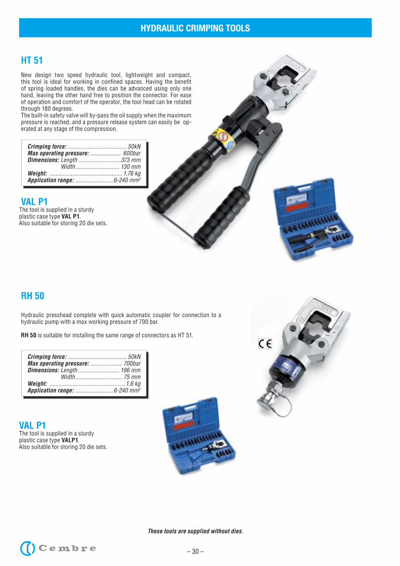
HYDRAULIC CRIMPING TOOLS
Crimping force: ....................................... 50kNMax operating pressure: .................... 600barDimensions: Length ............................373 mm Width ............................. 130 mmWeight: ................................................ 1,76 kgApplication range: .........................6-240 mm2
HT 51New design two speed hydraulic tool, lightweight and compact, this tool is ideal for working in confined spaces. Having the benefit of spring loaded handles, the dies can be advanced using only one hand, leaving the other hand free to position the connector. For ease of operation and comfort of the operator, the tool head can be rotated through 180 degrees.The built-in safety valve will by-pass the oil supply when the maximum pressure is reached, and a pressure release system can easily be op-erated at any stage of the compression.
VAL P1The tool is supplied in a sturdyplastic case type VAL P1.Also suitable for storing 20 die sets.
These tools are supplied without dies.
Crimping force: ....................................... 50kNMax operating pressure: ..................... 700barDimensions: Length ........................... 196 mm Width ............................... 75 mmWeight: ..................................................1,6 kgApplication range: .........................6-240 mm2
RH 50
Hydraulic presshead complete with quick automatic coupler for connection to a hydraulic pump with a max working pressure of 700 bar.
RH 50 is suitable for installing the same range of connectors as HT 51.
VAL P1The tool is supplied in a sturdyplastic case type VALP1.Also suitable for storing 20 die sets.
– 31 –
HYDRAULIC CRIMPING TOOLS
Crimping force: ..................................... 120kNMax operating pressure: ..................... 700barDimensions: Length ........................... 488 mm Width ............................. 138 mmWeight: ..................................................5,7 kgApplication range: .......................10-400 mm2
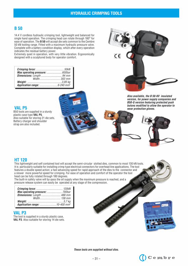
HT 120This lightweight and self contained tool will accept the semi-circular slotted dies, common to most 130 kN tools. It is particularly suitable for installing crimp type electrical connectors for overhead line applications. The tool features a double speed action: a fast advancing speed for rapid approach of the dies to the connector and a slower more powerful speed for crimping. For ease of operation and comfort of the operator the tool head can be fully rotated through 180 degrees.The built-in safety valve will by-pass the oil supply when the maximum pressure is reached, and a pressure release system can easily be operated at any stage of the compression.
VAL P3The tool is supplied in a sturdy plastic case,VAL P3. Also suitable for storing 14 die sets.
Crimping force: ....................................... 50kNMax operating pressure: ..................... 600barDimensions: Length ............................. 94 mm Width ............................. 302 mmWeight: ................................................3,85 kgApplication range: .........................6-240 mm2
B 5014.4 V cordless hydraulic crimping tool, lightweight and balanced for single hand operation. The crimping head can rotate through 180° for ease of operation. The B 50 will accept die sets common to the Cembre 50 kN tooling range. Fitted with a maximum hydraulic pressure valve. Complete with a battery condition display, which after every operation indicates the residual battery power. Extremely quiet in operation, with very little vibration. Ergonomically designed with a sculptured body for operator comfort.
VAL P5B50 tools are supplied in a sturdyplastic case type VAL P5.Also suitable for storing 21 die sets.Battery charger and shoulderstrap are also included.
Also available, the B 50-KV insulated version, for power supply companies and B50-G version featuring protected push butons modified to allow the operator to wear protection gloves.
These tools are supplied without dies.
– 32 –
HYDRAULIC CRIMPING HEADS
Crimping force: .................................... 130 kNMax operating pressure: .................... 700 barDimensions: Length ........................... 232 mm Width ..............................124 mmWeight: ..................................................3,9 kgApplication range: .......................10-400 mm2
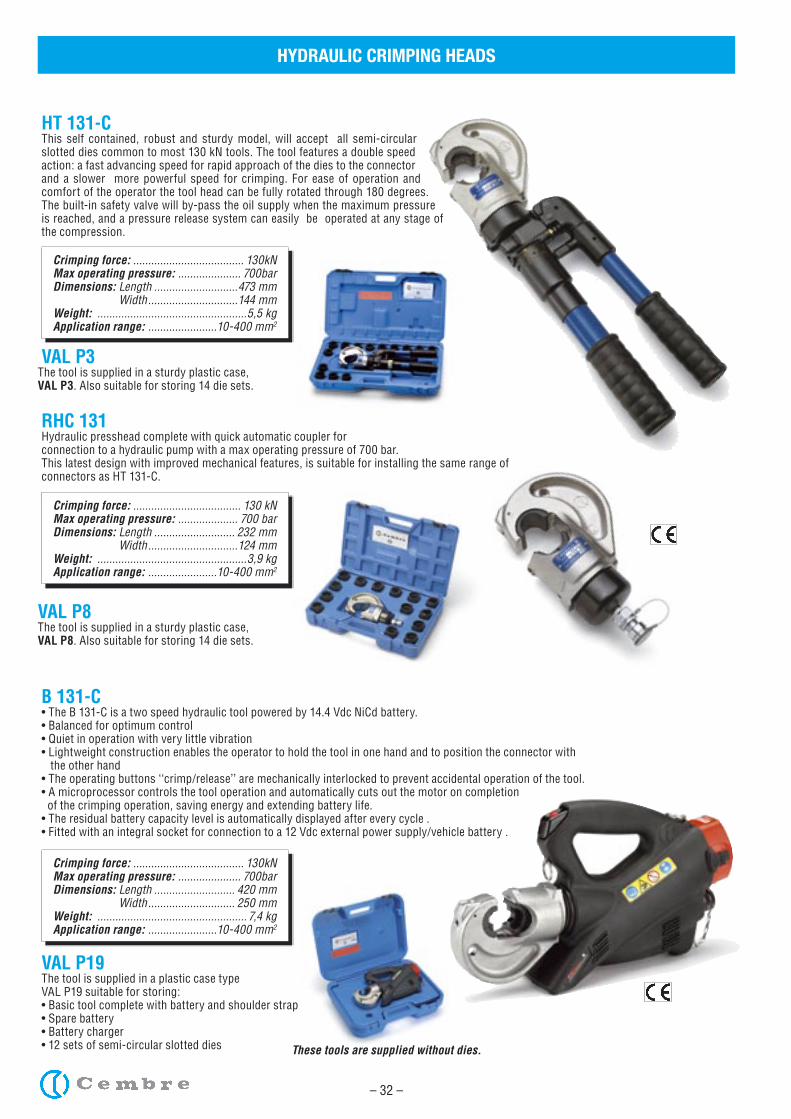
RHC 131Hydraulic presshead complete with quick automatic coupler for connection to a hydraulic pump with a max operating pressure of 700 bar.This latest design with improved mechanical features, is suitable for installing the same range of connectors as HT 131-C.
VAL P8The tool is supplied in a sturdy plastic case,VAL P8. Also suitable for storing 14 die sets.
These tools are supplied without dies.
Crimping force: ..................................... 130kNMax operating pressure: ..................... 700barDimensions: Length ............................473 mm Width ..............................144 mmWeight: ..................................................5,5 kgApplication range: .......................10-400 mm2
HT 131-CThis self contained, robust and sturdy model, will accept all semi-circular slotted dies common to most 130 kN tools. The tool features a double speed action: a fast advancing speed for rapid approach of the dies to the connector and a slower more powerful speed for crimping. For ease of operation and comfort of the operator the tool head can be fully rotated through 180 degrees. The built-in safety valve will by-pass the oil supply when the maximum pressure is reached, and a pressure release system can easily be operated at any stage of the compression.
VAL P3The tool is supplied in a sturdy plastic case,VAL P3. Also suitable for storing 14 die sets.
Crimping force: ..................................... 130kNMax operating pressure: ..................... 700barDimensions: Length ........................... 420 mm Width ............................. 250 mmWeight: .................................................. 7,4 kgApplication range: .......................10-400 mm2
B 131-C• The B 131-C is a two speed hydraulic tool powered by 14.4 Vdc NiCd battery. • Balanced for optimum control • Quiet in operation with very little vibration • Lightweight construction enables the operator to hold the tool in one hand and to position the connector with the other hand • The operating buttons ‘‘crimp/release’’ are mechanically interlocked to prevent accidental operation of the tool.• A microprocessor controls the tool operation and automatically cuts out the motor on completion of the crimping operation, saving energy and extending battery life.• The residual battery capacity level is automatically displayed after every cycle .• Fitted with an integral socket for connection to a 12 Vdc external power supply/vehicle battery .
VAL P19The tool is supplied in a plastic case type VAL P19 suitable for storing:• Basic tool complete with battery and shoulder strap• Spare battery • Battery charger• 12 sets of semi-circular slotted dies
– 33 –
HYDRAULIC CRIMPING HEADS
Crimping force: ..................................... 230kNMax operating pressure: ..................... 700barDimensions: Length ........................... 290 mm Width ............................. 120 mmWeight: ..................................................5,2 kgApplication range: ...................... 10-630 mm2
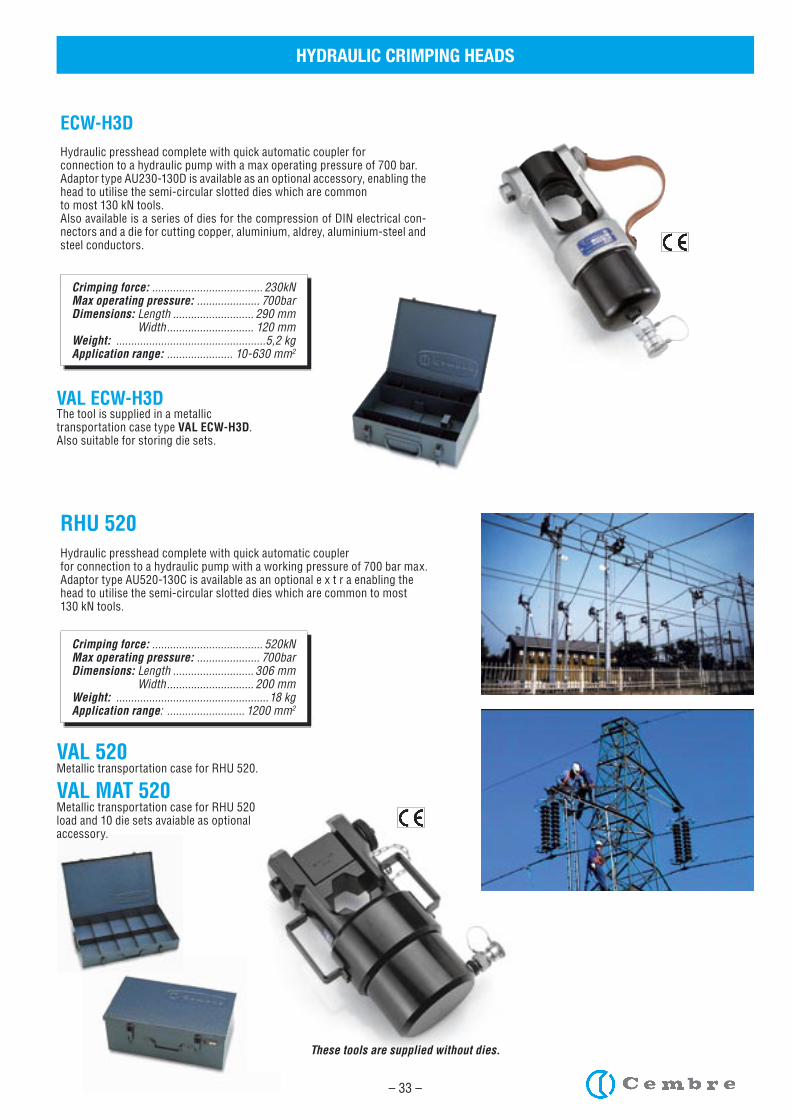
ECW-H3DHydraulic presshead complete with quick automatic coupler for connection to a hydraulic pump with a max operating pressure of 700 bar.Adaptor type AU230-130D is available as an optional accessory, enabling the head to utilise the semi-circular slotted dies which are common to most 130 kN tools.Also available is a series of dies for the compression of DIN electrical con-nectors and a die for cutting copper, aluminium, aldrey, aluminium-steel and steel conductors.
VAL ECW-H3DThe tool is supplied in a metallictransportation case type VAL ECW-H3D.Also suitable for storing die sets.
Crimping force: ..................................... 520kNMax operating pressure: ..................... 700barDimensions: Length ........................... 306 mm Width ............................. 200 mmWeight: ...................................................18 kgApplication range: .......................... 1200 mm2
RHU 520Hydraulic presshead complete with quick automatic couplerfor connection to a hydraulic pump with a working pressure of 700 bar max.Adaptor type AU520-130C is available as an optional e x t r a enabling thehead to utilise the semi-circular slotted dies which are common to most130 kN tools.
VAL 520Metallic transportation case for RHU 520.
VAL MAT 520Metallic transportation case for RHU 520 load and 10 die sets avaiable as optional accessory.
These tools are supplied without dies.
– 34 –
HYDRAULIC CABLE CUTTERS
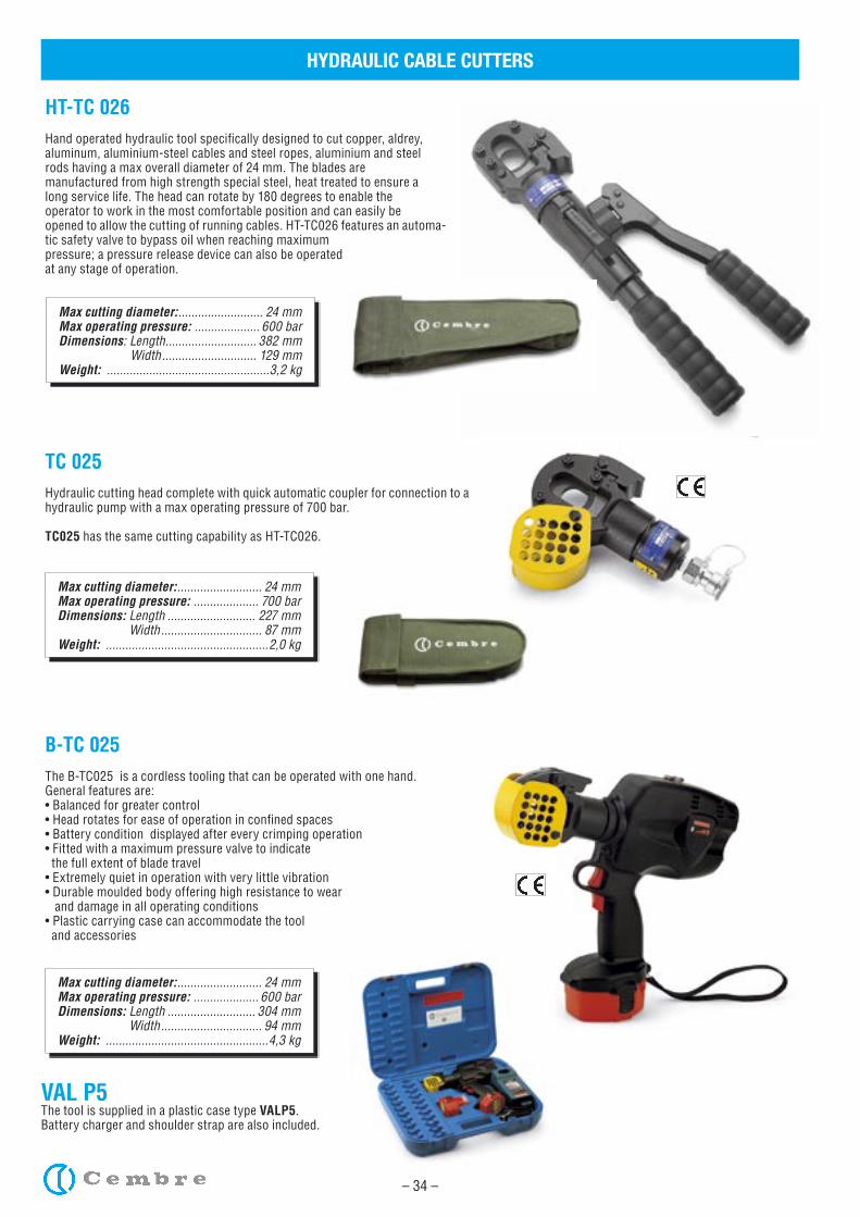
Max cutting diameter: .......................... 24 mmMax operating pressure: .................... 600 barDimensions: Length ............................ 382 mm Width ............................. 129 mmWeight: ..................................................3,2 kg
HT-TC 026Hand operated hydraulic tool specifically designed to cut copper, aldrey, aluminum, aluminium-steel cables and steel ropes, aluminium and steel rods having a max overall diameter of 24 mm. The blades aremanufactured from high strength special steel, heat treated to ensure along service life. The head can rotate by 180 degrees to enable theoperator to work in the most comfortable position and can easily beopened to allow the cutting of running cables. HT-TC026 features an automa-tic safety valve to bypass oil when reaching maximum pressure; a pressure release device can also be operatedat any stage of operation.
Max cutting diameter: .......................... 24 mmMax operating pressure: .................... 700 barDimensions: Length ........................... 227 mm Width ............................... 87 mmWeight: ..................................................2,0 kg
TC 025Hydraulic cutting head complete with quick automatic coupler for connection to a hydraulic pump with a max operating pressure of 700 bar.
TC025 has the same cutting capability as HT-TC026.
Max cutting diameter: .......................... 24 mmMax operating pressure: .................... 600 barDimensions: Length ........................... 304 mm Width ............................... 94 mmWeight: ..................................................4,3 kg
B-TC 025The B-TC025 is a cordless tooling that can be operated with one hand. General features are:• Balanced for greater control• Head rotates for ease of operation in confined spaces• Battery condition displayed after every crimping operation• Fitted with a maximum pressure valve to indicate the full extent of blade travel• Extremely quiet in operation with very little vibration• Durable moulded body offering high resistance to wear and damage in all operating conditions• Plastic carrying case can accommodate the tool and accessories
VAL P5The tool is supplied in a plastic case type VALP5.Battery charger and shoulder strap are also included.
– 35 –
HYDRAULIC CABLE CUTTERS
Max cutting diameter: .......................... 40 mmMax operating pressure: .................... 700 barDimensions: Length ........................... 550 mm Width ..............................144 mmWeight: ..................................................5,8 kg
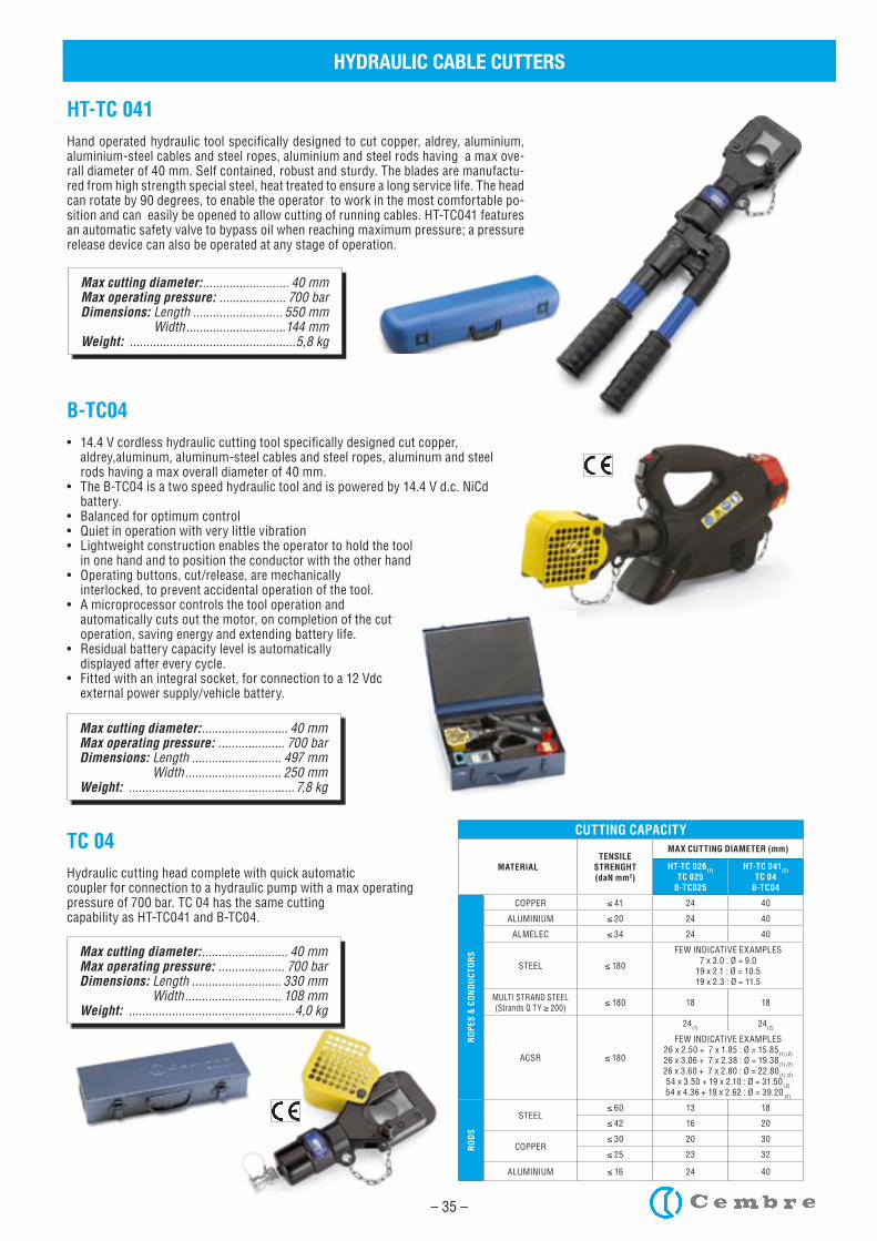
HT-TC 041Hand operated hydraulic tool specifically designed to cut copper, aldrey, aluminium, aluminium-steel cables and steel ropes, aluminium and steel rods having a max ove-rall diameter of 40 mm. Self contained, robust and sturdy. The blades are manufactu-red from high strength special steel, heat treated to ensure a long service life. The head can rotate by 90 degrees, to enable the operator to work in the most comfortable po-sition and can easily be opened to allow cutting of running cables. HT-TC041 features an automatic safety valve to bypass oil when reaching maximum pressure; a pressure release device can also be operated at any stage of operation.
Max cutting diameter: .......................... 40 mmMax operating pressure: .................... 700 barDimensions: Length ........................... 330 mm Width ............................. 108 mmWeight: ..................................................4,0 kg
TC 04Hydraulic cutting head complete with quick automaticcoupler for connection to a hydraulic pump with a max operatingpressure of 700 bar. TC 04 has the same cuttingcapability as HT-TC041 and B-TC04.
Max cutting diameter: .......................... 40 mmMax operating pressure: .................... 700 barDimensions: Length ........................... 497 mm Width ............................. 250 mmWeight: .................................................. 7,8 kg
B-TC04• 14.4 V cordless hydraulic cutting tool specifically designed cut copper, aldrey,aluminum, aluminum-steel cables and steel ropes, aluminum and steel rods having a max overall diameter of 40 mm.• The B-TC04 is a two speed hydraulic tool and is powered by 14.4 V d.c. NiCd battery. • Balanced for optimum control • Quiet in operation with very little vibration • Lightweight construction enables the operator to hold the tool in one hand and to position the conductor with the other hand • Operating buttons, cut/release, are mechanically interlocked, to prevent accidental operation of the tool.• A microprocessor controls the tool operation and automatically cuts out the motor, on completion of the cut operation, saving energy and extending battery life.• Residual battery capacity level is automatically displayed after every cycle.• Fitted with an integral socket, for connection to a 12 Vdc external power supply/vehicle battery.
CUTTING CAPACITY
MATERIALTENSILE
STRENGHT(daN mm2)
MAX CUTTING DIAMETER (mm)
HT-TC 026(1) TC 025
B-TC025
HT-TC 041(2) TC 04
B-TC04
RO
PES
& C
ON
DU
CTO
RS
COPPER ≤ 41 24 40
ALUMINIUM ≤ 20 24 40
ALMELEC ≤ 34 24 40
STEEL ≤ 180
FEW INDICATIVE EXAMPLES7 x 3.0 : Ø = 9.0
19 x 2.1 : Ø = 10.519 x 2.3 : Ø = 11.5
MULTI STRAND STEEL (Strands Q TY ≥ 200) ≤ 180 18 18
ACSR ≤ 180
24(1) 24(2)
FEW INDICATIVE EXAMPLES26 x 2.50 + 7 x 1.85 : Ø = 15.85(1) (2)26 x 3.06 + 7 x 2.38 : Ø = 19.38(1) (2)26 x 3.60 + 7 x 2.80 : Ø = 22.80(1) (2)54 x 3.50 + 19 x 2.10 : Ø = 31.50 (2)54 x 4.36 + 19 x 2.62 : Ø = 39.20 (2)
RO
DS
STEEL≤ 60 13 18
≤ 42 16 20
COPPER≤ 30 20 30
≤ 25 23 32
ALUMINIUM ≤ 16 24 40
– 36 –
HYDRAULIC CABLE CUTTERS
Max cutting diameter: .......................... 50 mmMax operating pressure: .................... 600 barDimensions: Length ........................... 497 mm Width ............................. 129 mmWeight: ................................................4,38 kg
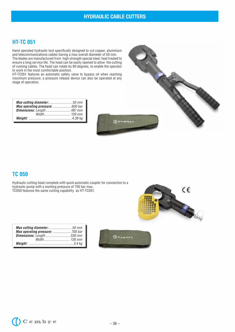
HT-TC 051Hand operated hydraulic tool specifically designed to cut copper, aluminium and telecommunications cables having a max overall diameter of 50 mm. The blades are manufactured from high strength special steel, heat treated to ensure a long service life. The head can be easily opened to allow the cutting of running cables. The head can rotate by 90 degrees, to enable the operator to work in the most comfortable position.HT-TC051 features an automatic safety valve to bypass oil when reaching maximum pressure; a pressure release device can also be operated at any stage of operation.
Max cutting diameter: .......................... 50 mmMax operating pressure: .................... 700 barDimensions: Length ........................... 330 mm Width ............................. 126 mmWeight: ..................................................3,4 kg
TC 050Hydraulic cutting head complete with quick automatic coupler for connection to a hydraulic pump with a working pressure of 700 bar max.TC050 features the same cutting capability as HT-TC051.
– 37 –
Max cutting diameter: .......................... 50 mmMax operating pressure: .................... 600 barDimensions: Length ........................... 304 mm Width ............................... 94 mmWeight: ................................................5,68 kg
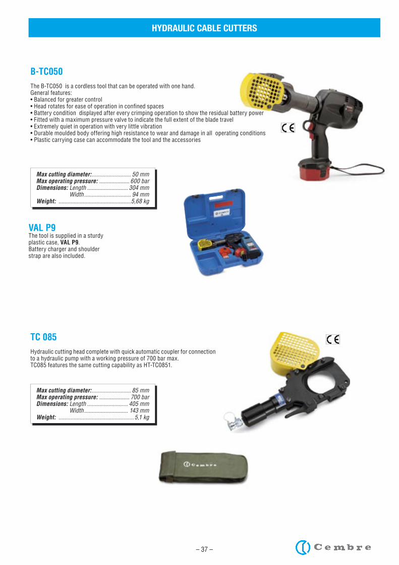
B-TC050The B-TC050 is a cordless tool that can be operated with one hand.General features:• Balanced for greater control• Head rotates for ease of operation in confined spaces• Battery condition displayed after every crimping operation to show the residual battery power• Fitted with a maximum pressure valve to indicate the full extent of the blade travel • Extremely quiet in operation with very little vibration• Durable moulded body offering high resistance to wear and damage in all operating conditions• Plastic carrying case can accommodate the tool and the accessories
VAL P9The tool is supplied in a sturdyplastic case, VAL P9.Battery charger and shoulderstrap are also included.
HYDRAULIC CABLE CUTTERS
Max cutting diameter: .......................... 85 mmMax operating pressure: .................... 700 barDimensions: Length ........................... 405 mm Width ............................. 143 mmWeight: ..................................................5,1 kg
TC 085Hydraulic cutting head complete with quick automatic coupler for connection to a hydraulic pump with a working pressure of 700 bar max.TC085 features the same cutting capability as HT-TC0851.
– 38 –
HYDRAULIC PUMPS
Max operating pressure: .................... 700 barDimensions: Length ........................... 680 mm Width ............................. 200 mm Height ............................ 163 mmWeight: ..................................................9,2 kg
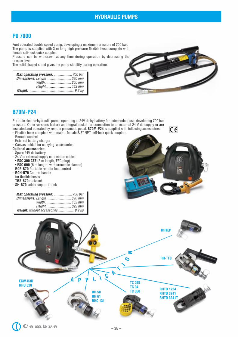
P0 7000Foot operated double speed pump, developing a maximum pressure of 700 bar. The pump is supplied with 3 m long high pressure flexible hose complete with female self-lock quick coupler.Pressure can be withdrawn at any time during operation by depressing the release lever.The solid shaped stand gives the pump stability during operation.
Max operating pressure: .................... 700 barDimensions: Length ........................... 390 mm Width ............................. 163 mm Height ............................ 323 mmWeight: without accessories ..................9,2 kg
B70M-P24Portable electro-hydraulic pump, operating at 24V dc by battery for independent use, developing 700 bar pressure. Other versions feature an integral socket for connection to an external 24 V dc supply or are insulated and operated by remote pneumatic pedal. B70M-P24 is supplied with following accessoires:– Flexible hose complete with male + female 3/8” NPT self-lock quick couplers– Remote control– External battery charger– Canvas holdall for carrying accessoriesOptional accessories:– Spare 24V dc battery– 24 Vdc external supply connection cables: • ESC 300 CEE (3 m length, EEC plug) • ESC 600 (6 m length, with crocodile clamps)– RCP-B70 Portable remote foot control – RCH-B70 Control handle for flexible hoses– TRS-B70 rucksack– SH-B70 ladder support hook
ECW-H3DRHU 520
RH 50RH 61RHC 131
TC 025TC 04TC 050 RHTD 1724
RHTD 3241RHTD 3241T
RH-TFC
RHTEP
A P P L I C AT
IO
N
– 39 –
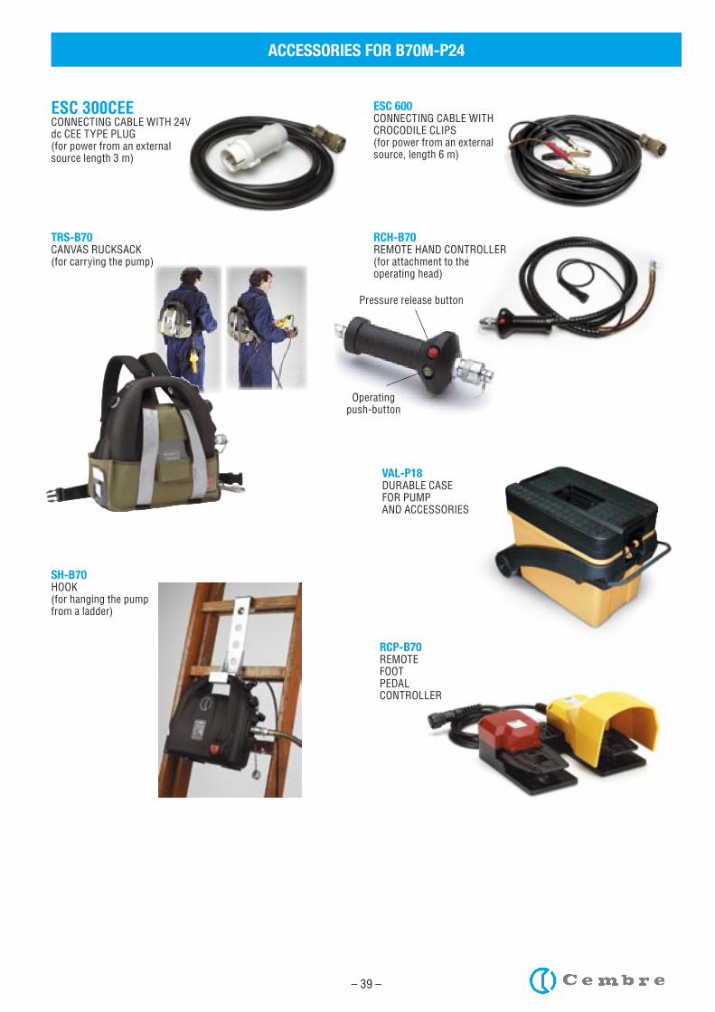
TRS-B70CANVAS RUCKSACK(for carrying the pump)
VAL-P18DURABLE CASE FOR PUMPAND ACCESSORIES
SH-B70HOOK(for hanging the pumpfrom a ladder)
ESC 300CEECONNECTING CABLE WITH 24V dc CEE TYPE PLUG(for power from an external source length 3 m)
ESC 600CONNECTING CABLE WITH CROCODILE CLIPS(for power from an external source, length 6 m)
RCP-B70REMOTEFOOTPEDALCONTROLLER
RCH-B70REMOTE HAND CONTROLLER(for attachment to the operating head)
Pressure release button
Operating push-button
ACCESSORIES FOR B70M-P24
– 40 –
Protection equipment
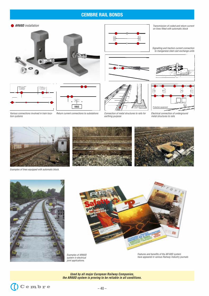
CEMBRE RAIL BONDS
AR60D installation Transmission of coded and return current on lines fitted with automatic block
Signalling and traction current connection to manganese steel cast exchange units
Various connections involved in train loca-tion systems
Return current connections to substations Connection of metal structures to rails for earthing purpose
Electrical connection of undergroundmetal structures to rails
Examples of lines equipped with automatic block.
Examples of AR60Dsystem in electricaljoint applications.
Features and benefits of the AR 60D systemhave appeared in various Railway Industry journals
Used by all major European Railway Companies, the AR60D system is proving to be reliable in all conditions.
The information contained in this catalogue is toaid the commercial selection of products.
It is not intended for use as an instruction manual.Information concerning application and the correctoperational use is provided by the specifi c manual
delivered with the products.
This catalogue is the property of Cembre.Any reproduction (in full or in part) is forbidden withoutthe prior written permission of Cembre.
Cembre reserve the right to modify the specifi cationsin this catalogue without prior notice.
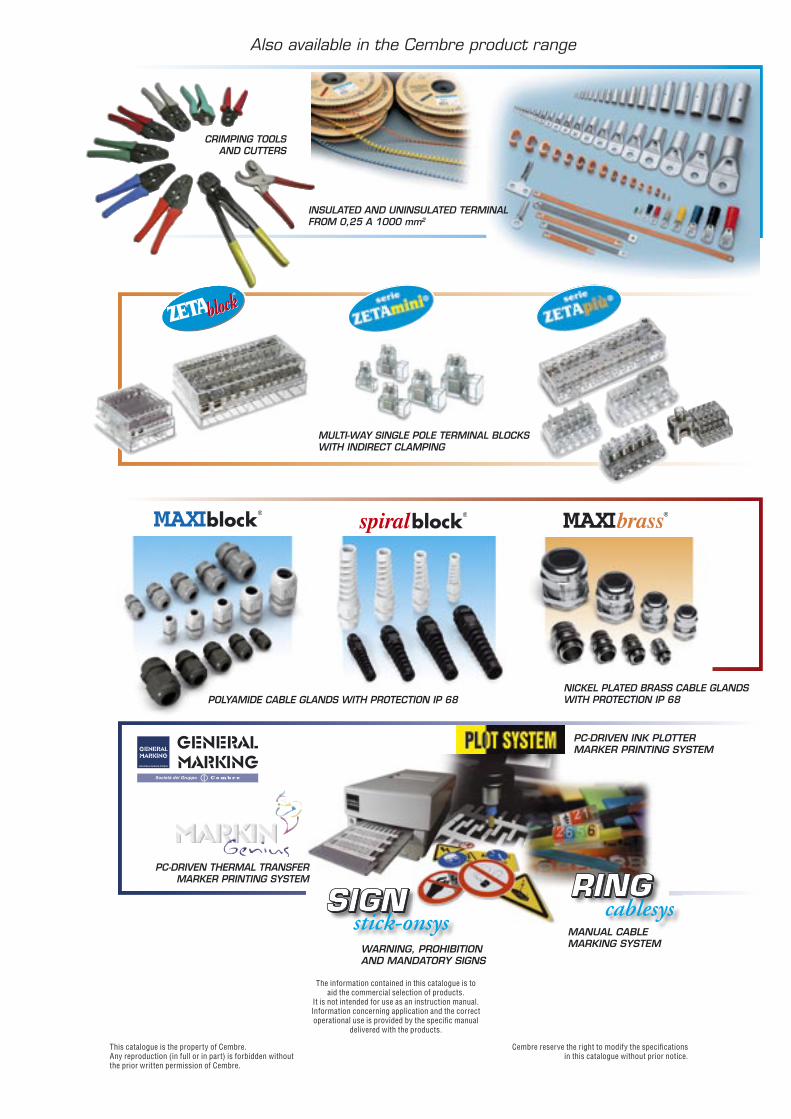
Also available in the Cembre product range
INSULATED AND UNINSULATED TERMINAL FROM 0,25 A 1000 mm2
MULTI-WAY SINGLE POLE TERMINAL BLOCKS WITH INDIRECT CLAMPING
NICKEL PLATED BRASS CABLE GLANDSWITH PROTECTION IP 68POLYAMIDE CABLE GLANDS WITH PROTECTION IP 68
MANUAL CABLE MARKING SYSTEMWARNING, PROHIBITION
AND MANDATORY SIGNS
PC-DRIVEN INK PLOTTER MARKER PRINTING SYSTEM
PC-DRIVEN THERMAL TRANSFER MARKER PRINTING SYSTEM
CRIMPING TOOLSAND CUTTERS

Dunton ParkKingsbury Road, CurdworthSutton Coldfield - West Midlands B76 9EETel.: 01675 470440Fax: 01675 470220 E-mail: [email protected]
Design, manufacture andstockholding of electrical connectorsand associated tooling.In house repair, refurbishment andassociated recalibration of tooling
Ltd.