Embed Size (px)
Citation preview

Motor Protection
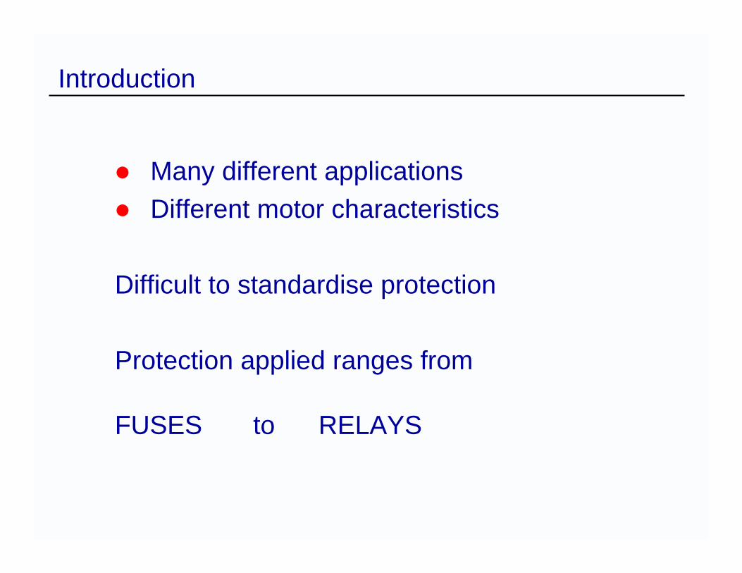
Many different applicationsDifferent motor characteristics
Difficult to standardise protection
Protection applied ranges from
FUSES to RELAYS
Introduction
Introduction
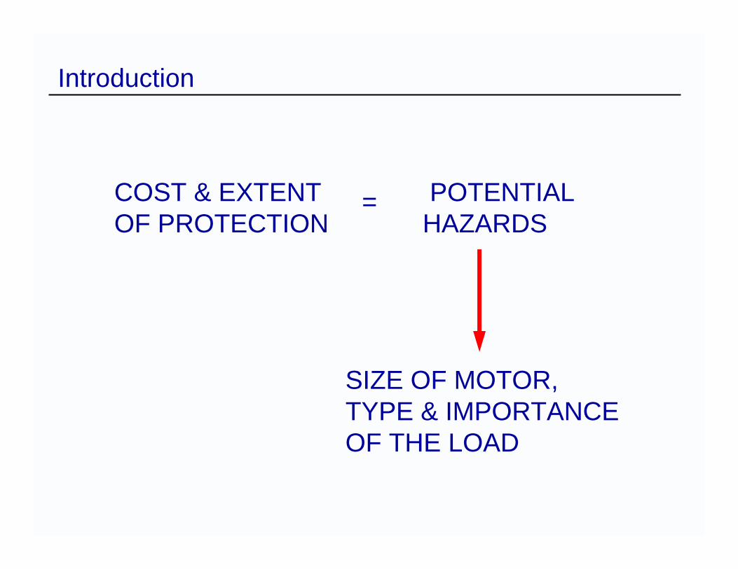
COST & EXTENT POTENTIALOF PROTECTION HAZARDS
SIZE OF MOTOR,TYPE & IMPORTANCEOF THE LOAD
=
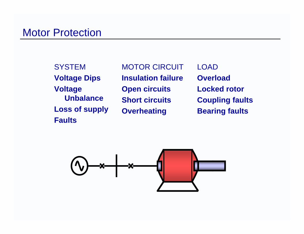
SYSTEMVoltage DipsVoltage
UnbalanceLoss of supplyFaults
Motor Protection
MOTOR CIRCUITInsulation failureOpen circuitsShort circuitsOverheating
LOADOverloadLocked rotorCoupling faultsBearing faults
Motor Protection Application
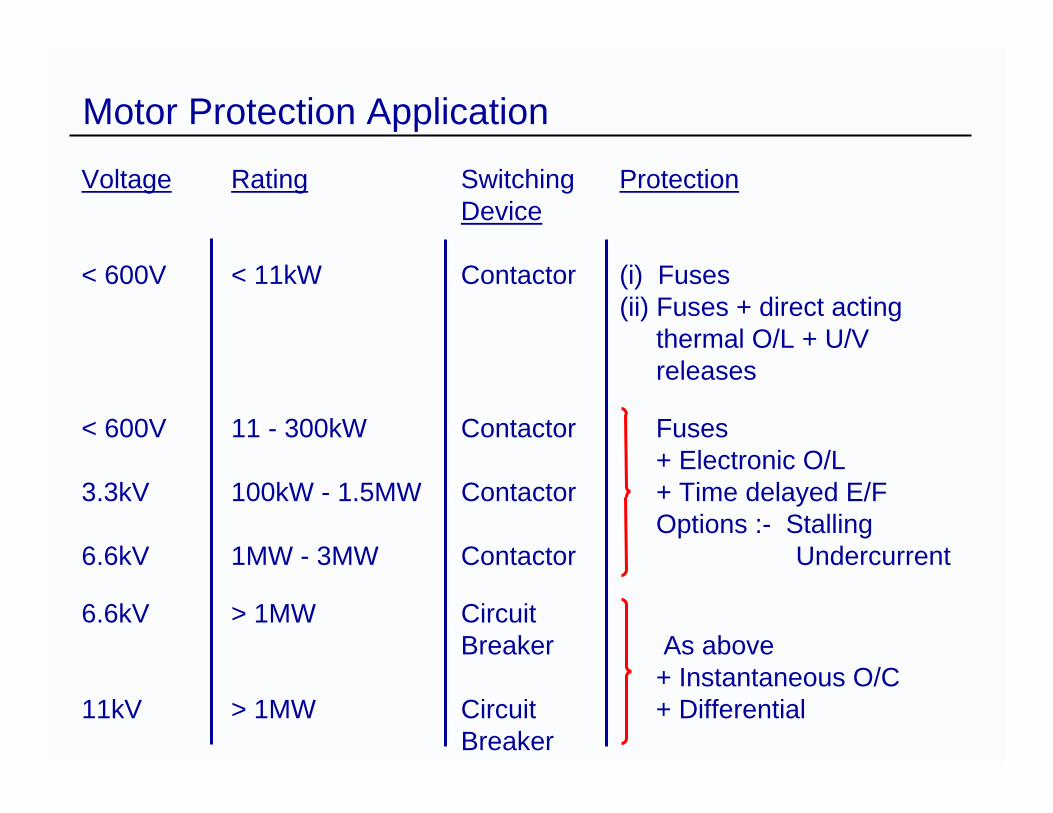
Voltage Rating Switching ProtectionDevice
< 600V < 11kW Contactor (i) Fuses(ii) Fuses + direct acting
thermal O/L + U/Vreleases
< 600V 11 - 300kW Contactor Fuses+ Electronic O/L
3.3kV 100kW - 1.5MW Contactor + Time delayed E/FOptions :- Stalling
6.6kV 1MW - 3MW Contactor Undercurrent
6.6kV > 1MW CircuitBreaker As above
+ Instantaneous O/C11kV > 1MW Circuit + Differential
Breaker
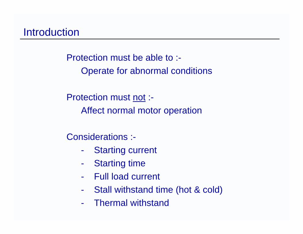
Protection must be able to :-Operate for abnormal conditions
Protection must not :-Affect normal motor operation
Considerations :-- Starting current- Starting time- Full load current- Stall withstand time (hot & cold)- Thermal withstand
Introduction

Mechanical Overload
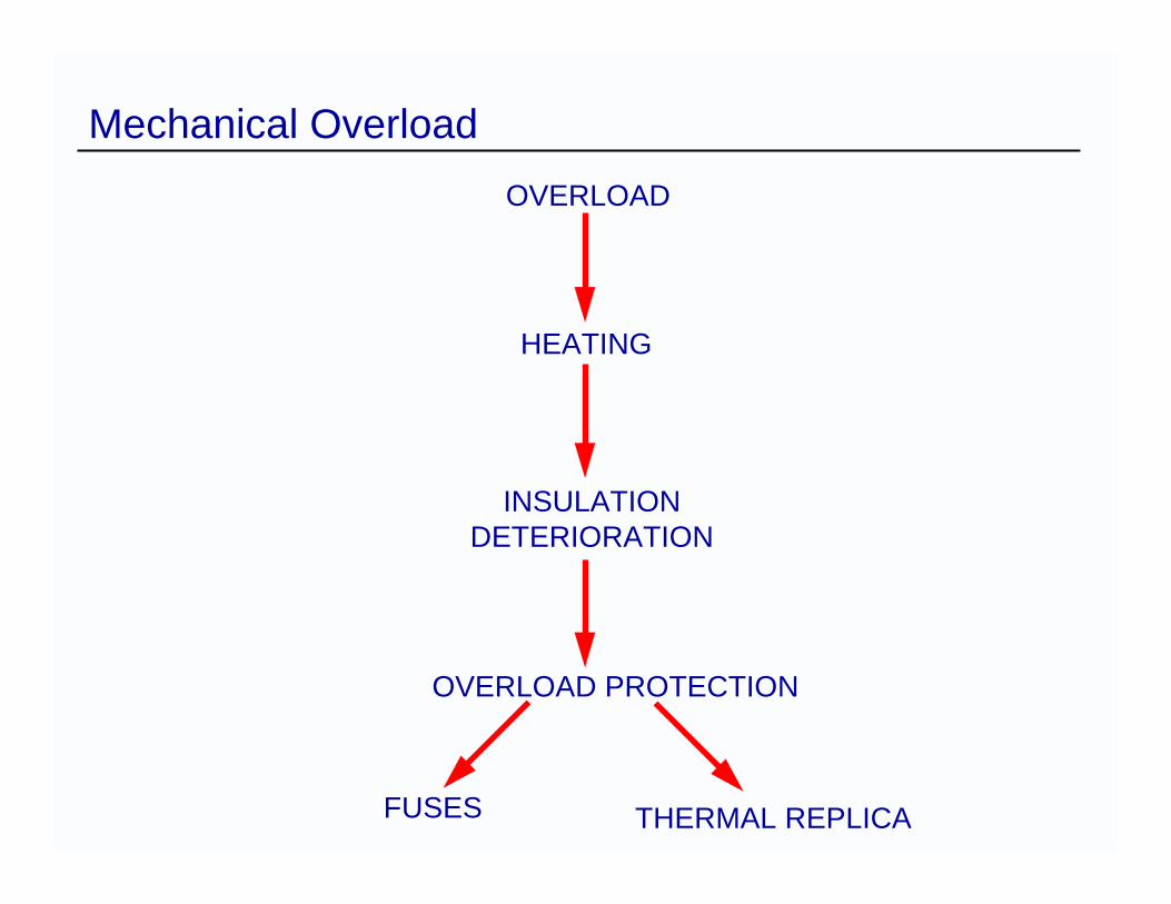
Mechanical OverloadOVERLOAD
HEATING
INSULATIONDETERIORATION
OVERLOAD PROTECTION
THERMAL REPLICAFUSES
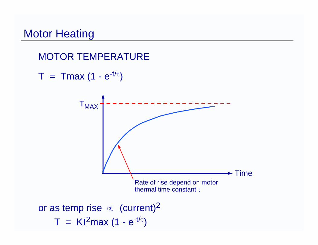
Motor Heating
MOTOR TEMPERATURE
T = Tmax (1 - e-t/τ)
or as temp rise ∝ (current)2
T = KI2max (1 - e-t/τ)
Rate of rise depend on motorthermal time constant τ
Time
TMAX
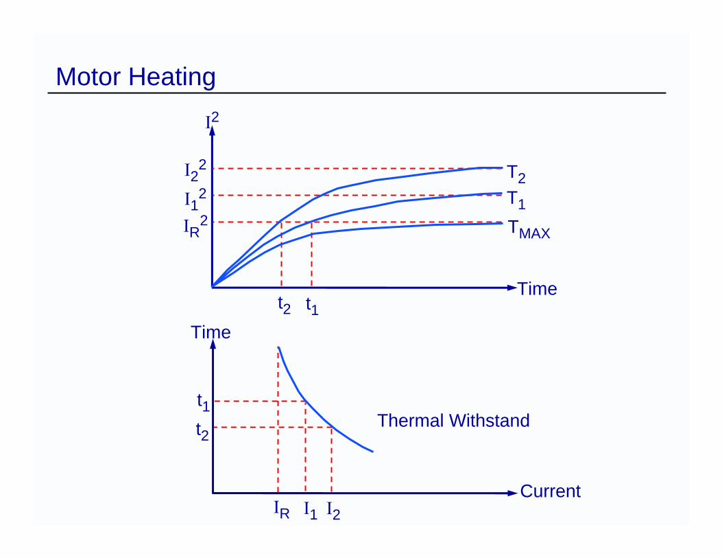
Motor Heating
Time
TMAX
T1
T2
t2 t1
I2
I22
I12
IR2
Time
CurrentIR I1 I2
t1t2
Thermal Withstand
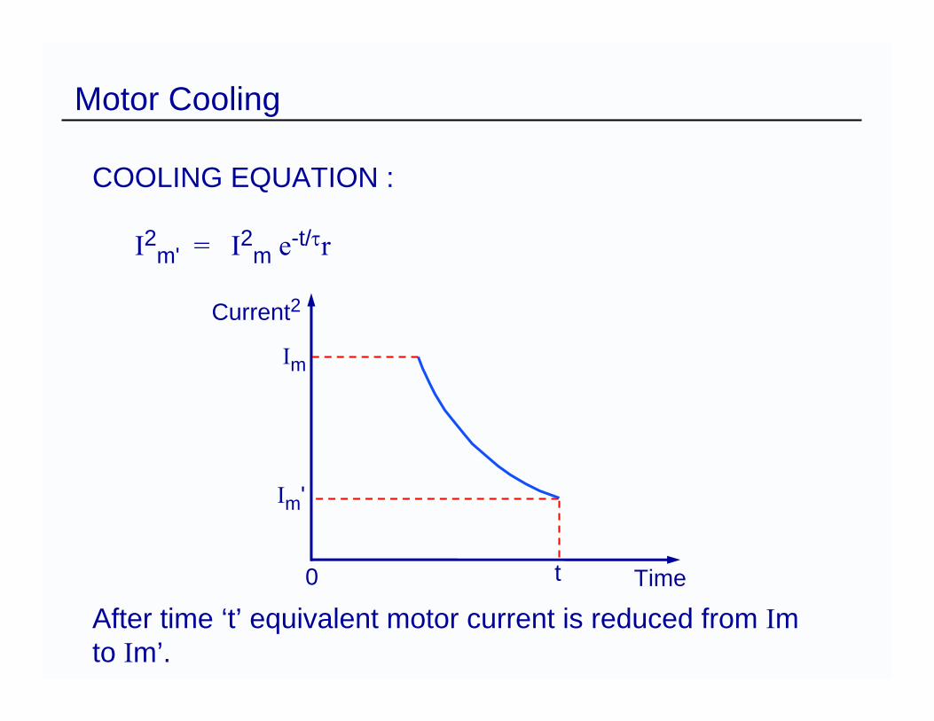
Motor Cooling
COOLING EQUATION :
I2m' = I2m e-t/τr
After time ‘t’ equivalent motor current is reduced from Imto Im’.
Time
Im
Current2
Im'
t0
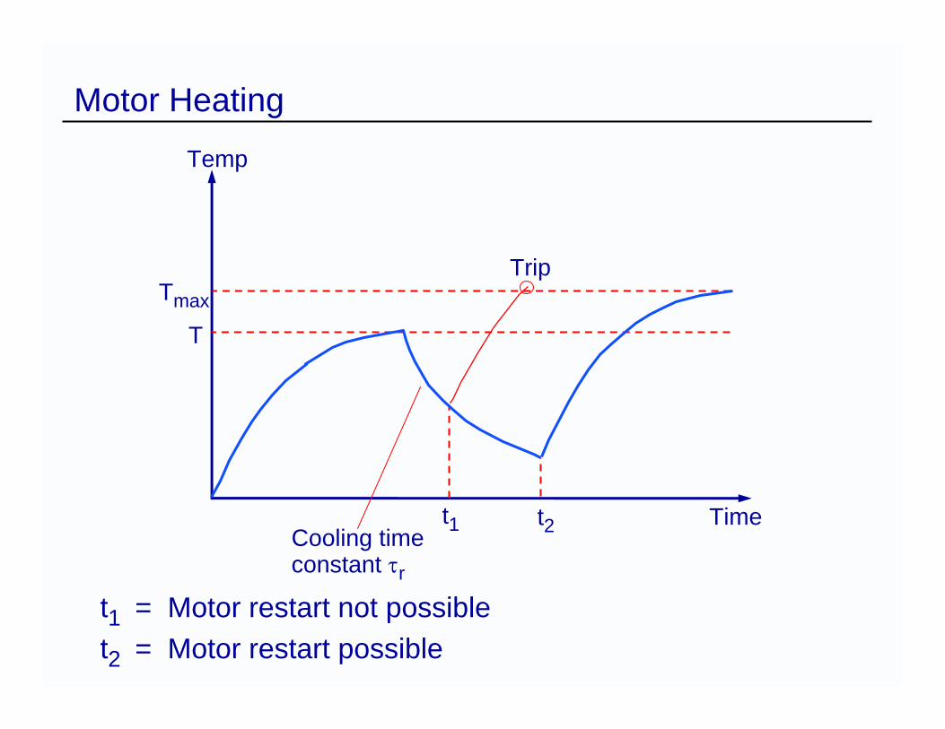
Motor Heating
t1 = Motor restart not possiblet2 = Motor restart possible
Time
Tmax
t2t1
Trip
Temp
Cooling timeconstant τr
T
Emergency Restart
In certain applications, such as mine exhaust and ship pumps, a machine restart is required knowing that it will result in reduced life or even permanent damage.
– All start up restrictions are inhibited– Thermal state limited to 90%

Start / Stall Protection
Stalling Protection
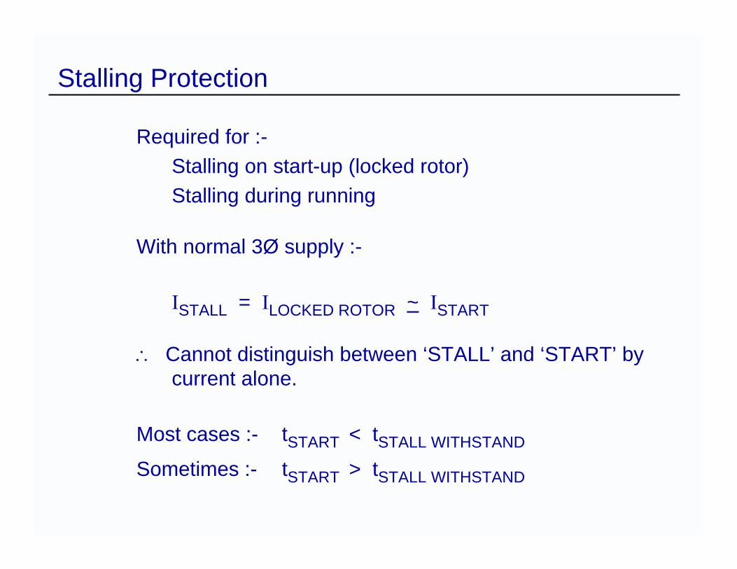
Required for :-Stalling on start-up (locked rotor)Stalling during running
With normal 3Ø supply :-
ISTALL = ILOCKED ROTOR ~ ISTART
∴ Cannot distinguish between ‘STALL’ and ‘START’ by current alone.
Most cases :- tSTART < tSTALL WITHSTAND
Sometimes :- tSTART > tSTALL WITHSTAND
Locked Rotor Protection Start Time < Stall Withstand Time
Where Starting Time is less than Stall Withstand Time :Use thermal protection characteristicUse dedicated locked rotor protection
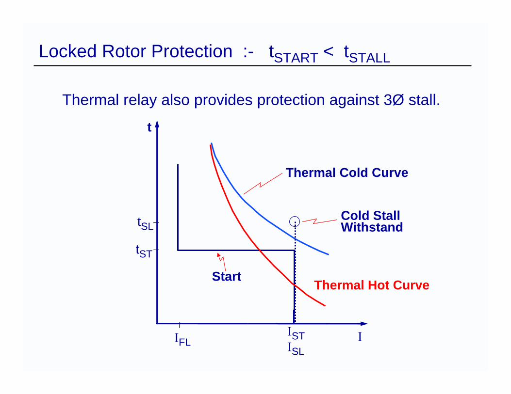
Locked Rotor Protection :- tSTART < tSTALL
Thermal relay also provides protection against 3Ø stall.
Thermal Cold Curve
Cold StallWithstand
Start
t
tSL
tST
IFLISTISL
I
Thermal Hot Curve
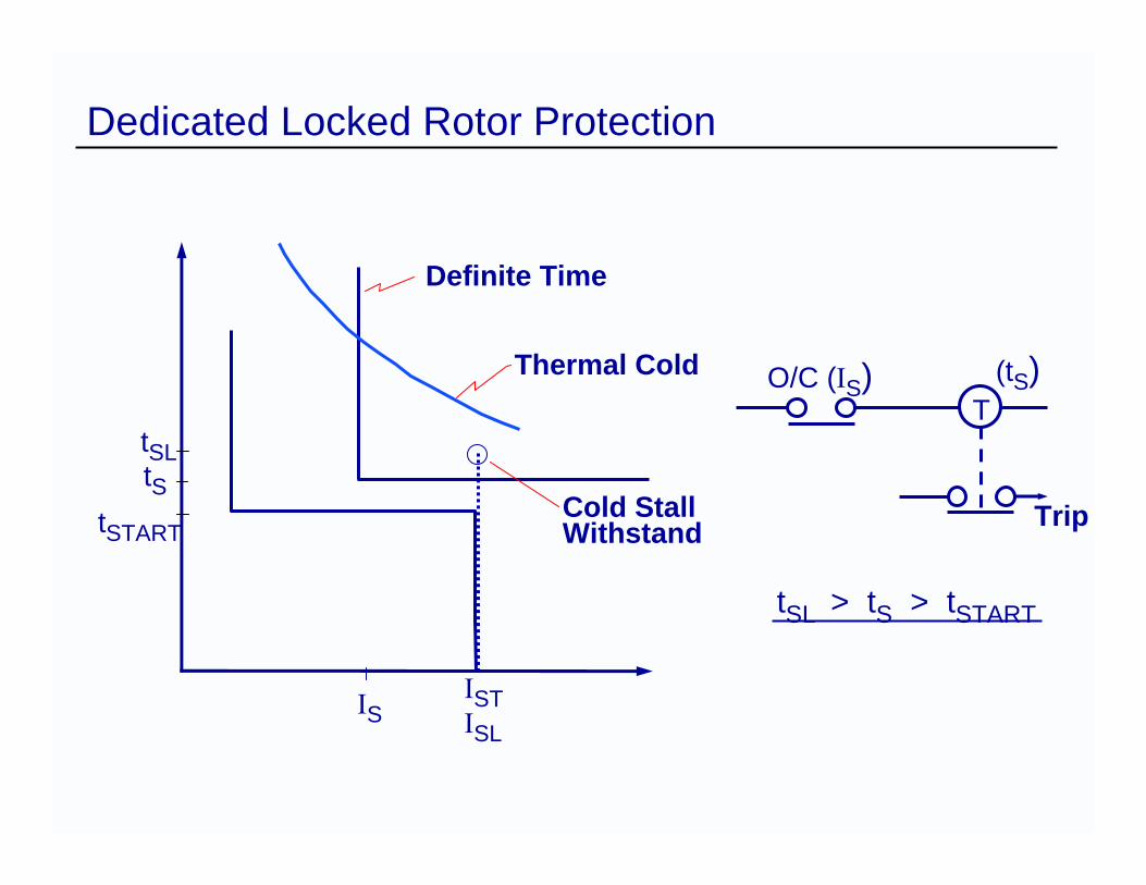
Dedicated Locked Rotor Protection
tSTART
Thermal Cold
Cold StallWithstand
tSLtS
ISISTISL
Definite Time
Trip
(tS)T
O/C (IS)
tSL > tS > tSTART
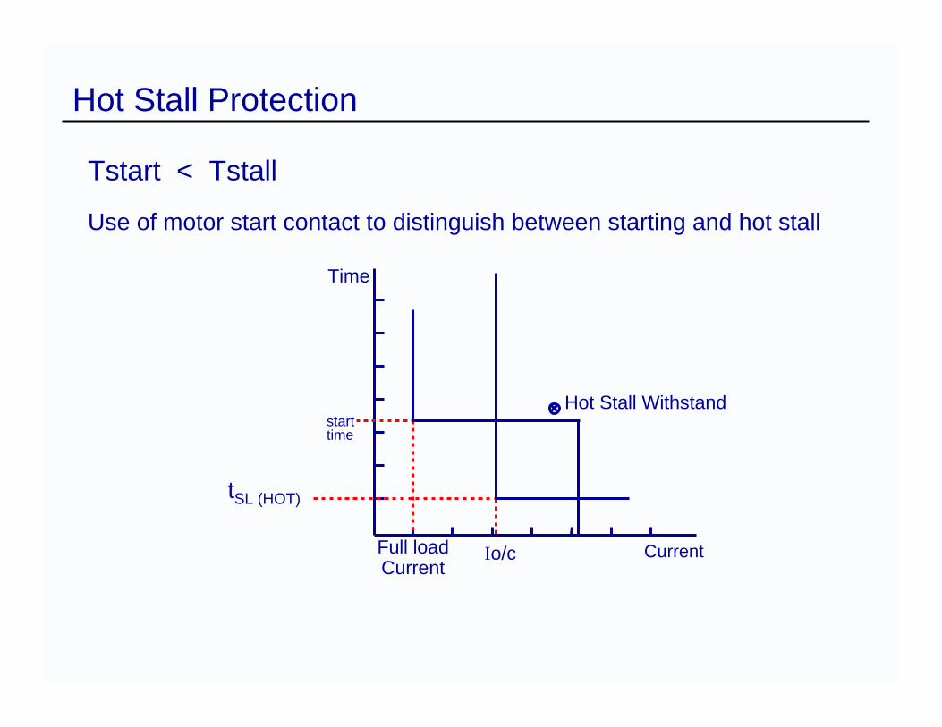
Hot Stall Protection
Tstart < Tstall
Use of motor start contact to distinguish between starting and hot stall
Current
Time
starttime
Full loadCurrent
Io/c
Hot Stall Withstand
tSL (HOT)
Motors with high inertia loads may often take longer to start than the stall withstand timeHowever, the rotor is not being damaged because, as the rotor turns the “skin effect” reduces, allowing the current to occupy more of the rotor windingThis reduces the heat generated and dissipates the existing heat over a greater area
Detect start using tachometer input
Locked Rotor Protection Start Time > Cold Stall Withstand
Stall Protection
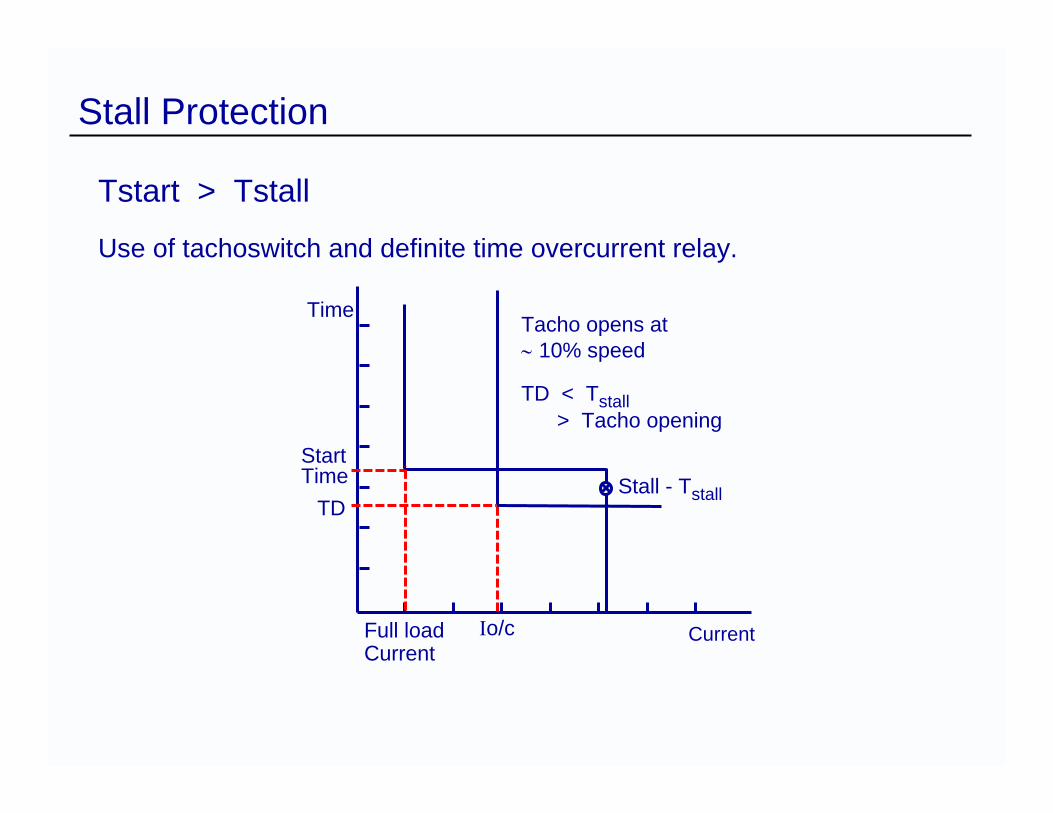
Tstart > Tstall
Use of tachoswitch and definite time overcurrent relay.
Time
StartTime
TD
Full loadCurrent
CurrentIo/c
Stall - Tstall
Tacho opens at∼ 10% speed
TD < Tstall> Tacho opening
Unbalanced Supply Protection
Operation on Supply Unbalance
Negative sequence impedance is much less than positive sequence impedance.
Small unbalance = relatively large negative sequence current.
Heating effect of negative sequence is greater than equivalent positive sequence current because they are HIGHER FREQUENCY.
Operation on Supply Unbalance
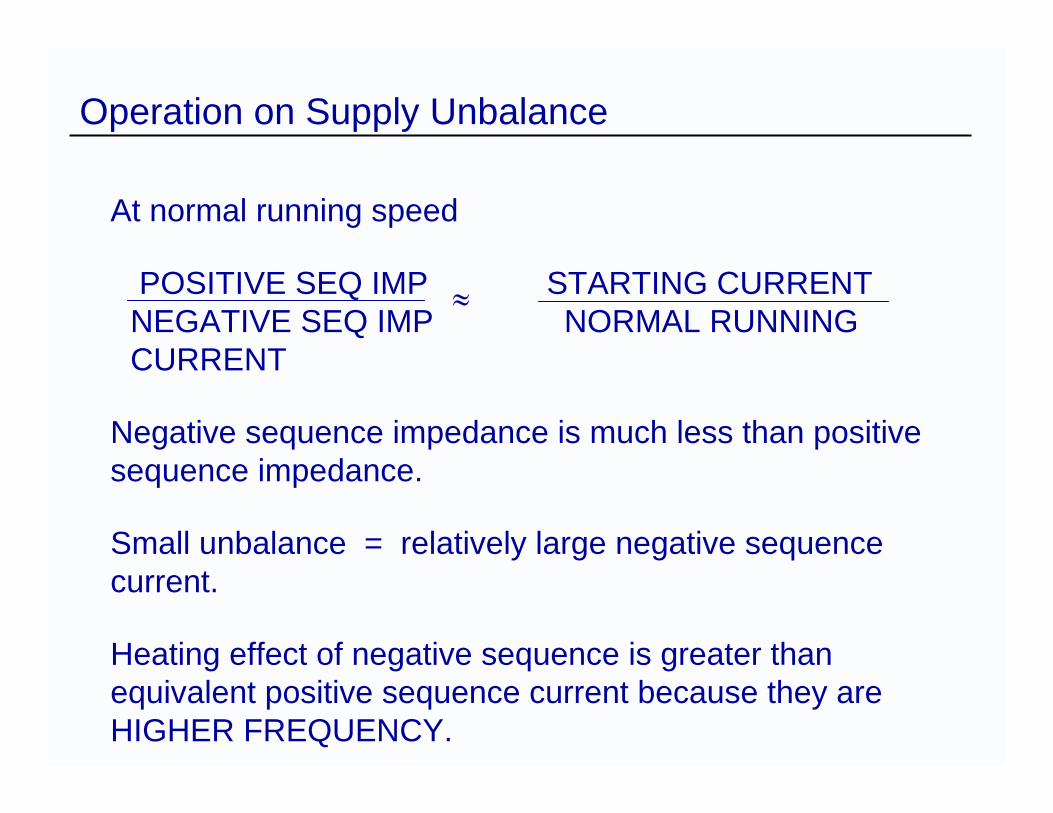
At normal running speed
POSITIVE SEQ IMP STARTING CURRENTNEGATIVE SEQ IMP NORMAL RUNNING CURRENT
Negative sequence impedance is much less than positive sequence impedance.
Small unbalance = relatively large negative sequence current.
Heating effect of negative sequence is greater than equivalent positive sequence current because they are HIGHER FREQUENCY.
≈
Equivalent Motor Current
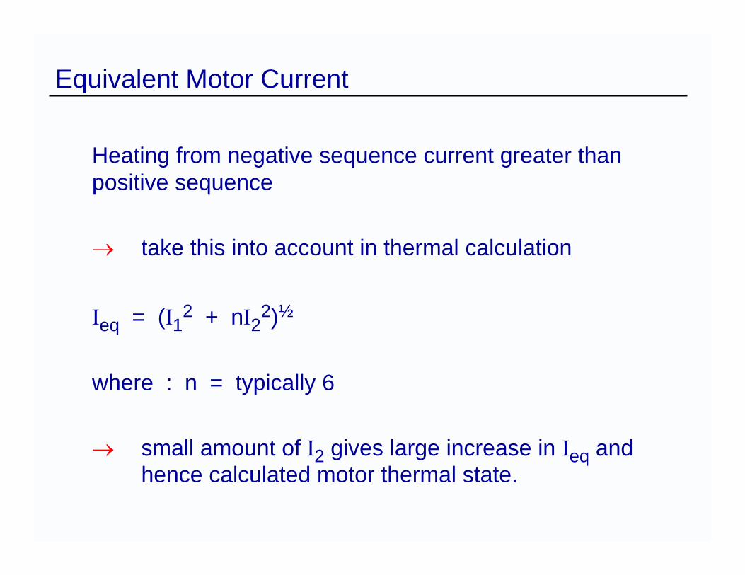
Heating from negative sequence current greater than positive sequence
→ take this into account in thermal calculation
Ieq = (I12 + nI22)½
where : n = typically 6
→ small amount of I2 gives large increase in Ieq and hence calculated motor thermal state.
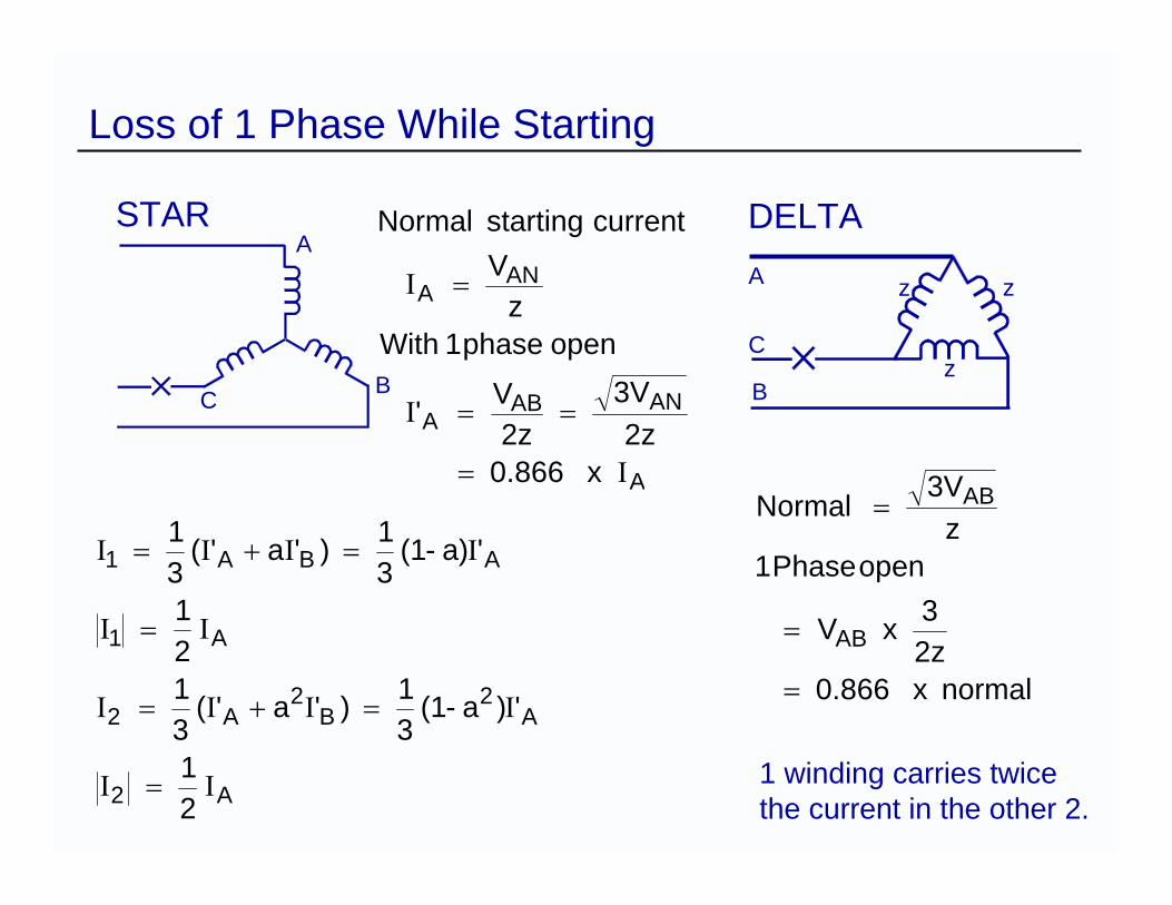
Loss of 1 Phase While Starting
A
ANABA
ANA
x 0.866 2z
3V 2z
V '
open phase 1 Withz
V
currentstartingNormal
Ι
Ι
Ι
=
==
=
A2
A2
B2
A2
A1
ABA1
21
')a-(1 31 )'a '(
31
21
'a)-(1 31 )'a '(
31
ΙΙ
ΙΙΙΙ
ΙΙ
ΙΙΙΙ
=
=+=
=
=+=
STAR DELTA
normalx 0.866 2z3x V
open Phase 1z
3V Normal
AB
AB
=
=
=
A
z
z
z
BC
A
B
C
1 winding carries twicethe current in the other 2.
Single Phase Stalling Protection
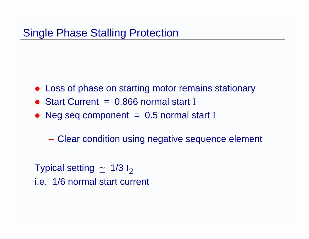
Loss of phase on starting motor remains stationaryStart Current = 0.866 normal start INeg seq component = 0.5 normal start I
– Clear condition using negative sequence element
Typical setting ~ 1/3 I2i.e. 1/6 normal start current
Single Phasing While Running
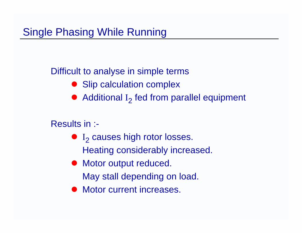
Difficult to analyse in simple termsSlip calculation complexAdditional I2 fed from parallel equipment
Results in :-I2 causes high rotor losses.Heating considerably increased.Motor output reduced.May stall depending on load.Motor current increases.
Reverse Phase Sequence Starting
Protection required for lift motors, conveyors
Instantaneous I2 unit
Time delayed thermal trip
Separate phase sequence detector for low load current machines

Undervoltage Protection
Undervoltage Considerations
Reduced torqueIncreased stator currentReduced speedFailure to run-up
Form of undervoltage condition :-Slight but prolonged (regulation)Large transient dip (fault clearance)
Undervoltage protection :-Disconnects motor from failed supplyDisconnects motor after dip long enough to prevent successful re-acceleration
Undervoltage Considerations
U/V tripping should be delayed for essential motors so that they may be given a chance to re-accelerate following a short voltage dip (< 0.5s)
Delayed drop-out of fused contactor could be arranged by using a capacitor in parallel with the AC holding coil
Insulation Failure
Insulation Failure
Results of prolonged or cyclic overheating
Instantaneous Earth Fault ProtectionInstantaneous Overcurrent ProtectionDifferential Protection on some large machines
Stator Earth Fault Protection
M
50
M
50
Rstab
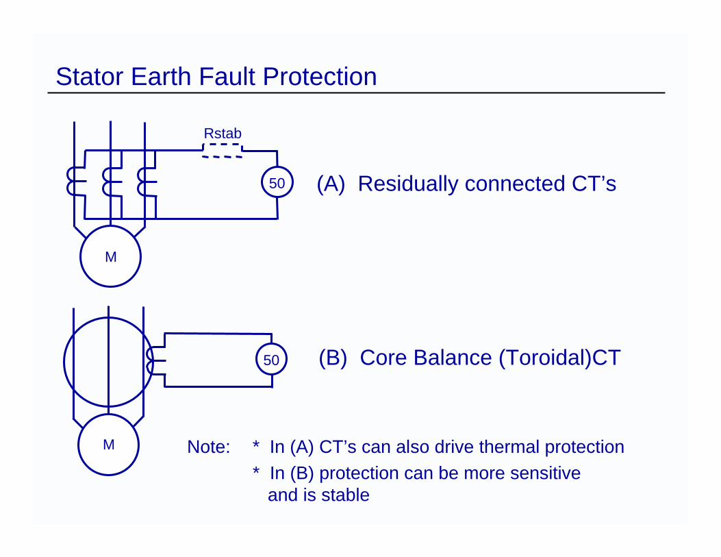
(A) Residually connected CT’s
(B) Core Balance (Toroidal)CT
Note: * In (A) CT’s can also drive thermal protection* In (B) protection can be more sensitive
and is stable
50Short Circuit
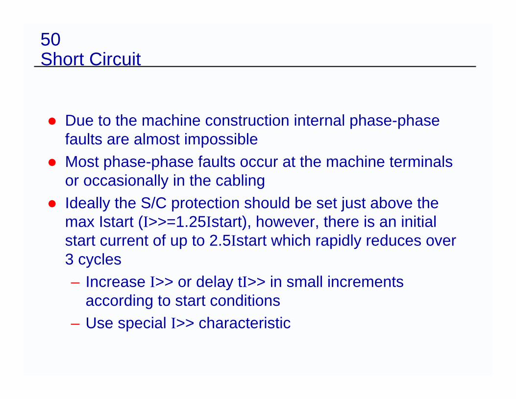
Due to the machine construction internal phase-phase faults are almost impossibleMost phase-phase faults occur at the machine terminals or occasionally in the cablingIdeally the S/C protection should be set just above the max Istart (I>>=1.25Istart), however, there is an initial start current of up to 2.5Istart which rapidly reduces over 3 cycles– Increase I>> or delay tI>> in small increments
according to start conditions– Use special I>> characteristic
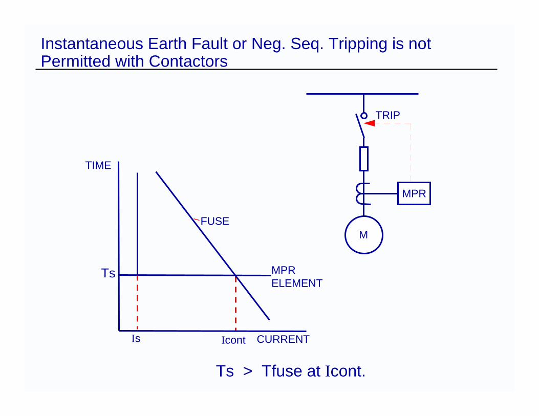
Instantaneous Earth Fault or Neg. Seq. Tripping is not Permitted with Contactors
TRIP
MPR
M
TIME
Ts
Is Icont CURRENT
FUSE
MPRELEMENT
Ts > Tfuse at Icont.

Differential Protection
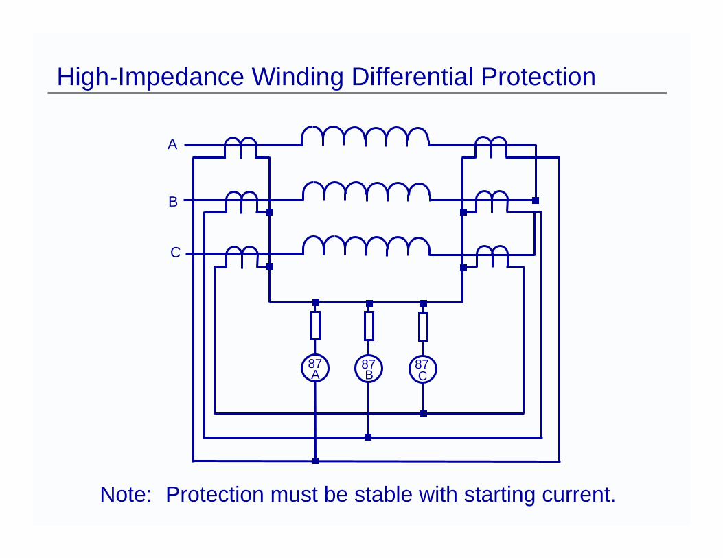
High-Impedance Winding Differential Protection
A
B
C
87A
87B
87C
Note: Protection must be stable with starting current.
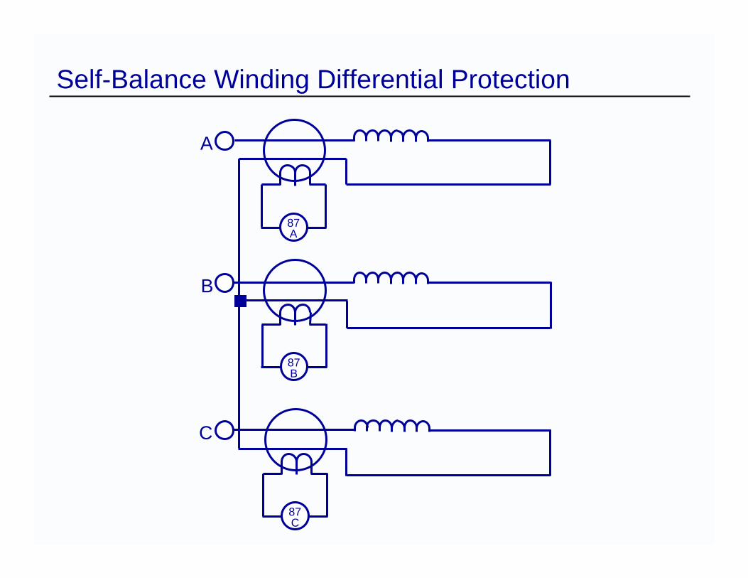
Self-Balance Winding Differential Protection
A
87A
B
C
87A
87B
87C
Bearings
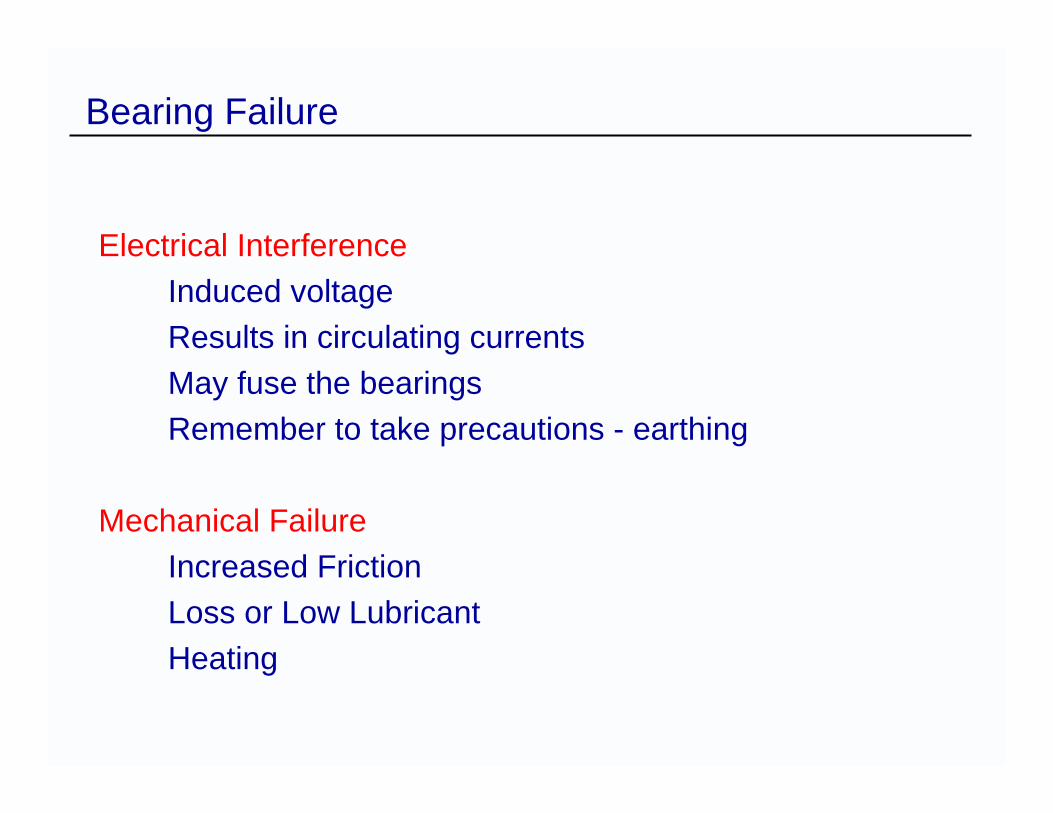
Bearing Failure
Electrical InterferenceInduced voltageResults in circulating currentsMay fuse the bearingsRemember to take precautions - earthing
Mechanical FailureIncreased FrictionLoss or Low LubricantHeating
Use of RTDs
RTD sensors at known stator hotspots
Absolute temperature measurements to bias the relay thermal characteristic
Monitoring of motor / load bearing temperatures
Ambient air temperature measurement
Synchronous Motors
Synchronous Machines
OUT OF STEP PROTECTIONInadequate field or excessive load can cause the machine to fall out of step. This subjects the machine to overcurrent and pulsating torque leading to stalling
>Field Current MethodDetect AC Current Induced In Field Circuit.
>Power Factor MethodDetect Heavy Current At Low Power Factor.
Synchronous Machines
LOSS OF SUPPLYOn Loss Of Supply Motor Should Be Disconnected If Supply Could Be Restored Automatically.Avoids Supply Being Restored Out Of Phase.
>Over voltage & Under frequency>Under power & Reverse Power