Embed Size (px)
Citation preview

8/11/2019 05 Component Sizing
http://slidepdf.com/reader/full/05-component-sizing 1/67
International MSc Programme Sustainable Energy EngineeringInternational MSc Programme Sustainable Energy Engineering
THERMAL COMFORT AND INDOOR CLIMATE
Lecture:
- HVAC SYSTEMS COMPONENT SIZING- AUTOMATIC CONTROL
Assist. Prof. Igor BALEN

8/11/2019 05 Component Sizing
http://slidepdf.com/reader/full/05-component-sizing 2/67
Heating coil
- factors that should be considered in coil selection:
• Required duty or capacity considering other components
• Temperature of air entering the coil and air temperature rise
• Available heating media, its operating and maximum pressure(s) and
temperature(s)
• Air volume, velocity, distribution, and limitations
• Heating media volume, flow velocity, distribution, and limitations
• Permissible flow resistances for both the air and heating media
• Individual installation requirements, such as the type of control and
material compatibility
• Specified and applicable codes and standards regulating the design and
installation

8/11/2019 05 Component Sizing
http://slidepdf.com/reader/full/05-component-sizing 3/67
Heating coil
- total design heat load for a building according to EN12831:

8/11/2019 05 Component Sizing
http://slidepdf.com/reader/full/05-component-sizing 4/67
Heating coil
1
2
- humidity ratio stays unchanged while
temperature increases (heating) ordecreases (cooling) and relative
humidity changes
)t t (.hh
)hh(mQ a
1212
1221
011 −=−
−=−
&& [kW]
h2-h
1
h 2 =
c o n s t .
h 1 =
c o n s t .
[kJ/kgdry air ]
- sensible heating:

8/11/2019 05 Component Sizing
http://slidepdf.com/reader/full/05-component-sizing 5/67
Heating coil
- coil sizing when heating load is known:
OA HL HC
QQQ &&& += [W]
- heating up of outdoor air to the room temperature is calculated from:
)( oi pOAOA t t cV Q −=
ρ &&
[W]
- coil is selected from the producer’s catalogue.
- coil sizing when designing the exchanger:
m HC t UAQ Δ=& [W]
Mean logarithmic temperature difference

8/11/2019 05 Component Sizing
http://slidepdf.com/reader/full/05-component-sizing 6/67
Heating coil
- water coil:
- usually use the standard construction materials of copper tube and
aluminum fins.
- generally have horizontal tubes to avoid air pockets. Where water coils
may be exposed to a freezing condition, drainability must be considered.This also applies when glycol fluid is circulated in the coil.

8/11/2019 05 Component Sizing
http://slidepdf.com/reader/full/05-component-sizing 7/67
Heating coil
- steam coil:
- for horizontal airflow, the tubes can be either vertical or horizontal.
- in basic coils, steam supply connection is at one end and the tubes are
pitched toward the condensate return, which is usually at the opposite end.
- when the entering air temperature is at or below 0°C, the steam supply to
the coil should not be modulated, but controlled as full on or full off. During
part-load conditions, air can be bypassed around the steam coil with full
steam flow to the coil.

8/11/2019 05 Component Sizing
http://slidepdf.com/reader/full/05-component-sizing 8/67
Heating coil
Coil ratings (ARI Standard 410):
Air face velocity. 1 to 8 m/s, based on air density of 1.2 kg/m3
Entering air temperature. Steam coils: −29 to 38°CWater coils: −18 to 38°C
Steam pressure. 15 to 1700 kPa (gage) at the coil steam supply
connection (pressure drop through the steam control valve must be
considered)
Fluid temperatures. Water: 50 to 120°C
Ethylene glycol: Up to 93°C
Fluid velocities. Water: 0.2 to 2.4 m/s
Ethylene glycol: 0.2 to 1.8 m/s

8/11/2019 05 Component Sizing
http://slidepdf.com/reader/full/05-component-sizing 9/67
Heating coil
Overall requirements:
- air face velocity is usually between 2.5 and 5 m/s.
- supply air temperature varies from about 22°C for ventilation only to
about 65°C for complete heating.
- steam pressure typically varies from 15 to 100 kPa (gage), with 35 kPa
(gage) being the most common. A minimum steam pressure of 35 kPa
(gage) is recommended for systems with entering air temperatures below
freezing.
- water velocities vary between 1.2 and 1.8 m/s. For high-temperature
water, water temperatures can range upwards of 200°C with operating
pressures of 100 to 170 kPa over saturated water temperature.

8/11/2019 05 Component Sizing
http://slidepdf.com/reader/full/05-component-sizing 10/67
Heating coil
Overall requirements (continued):
- water quantity is usually based on about an 10 - 20 K temperature drop
through the coil.
- high-temperature water systems commonly have a water temperature
between 130 and 200°C, with up to 60 K drop through the coil.
-air resistance is usually limited to 100 - 150 Pa for commercial buildings
and to about 250 Pa for industrial buildings.
- steam coils are selected with dry steam velocities not exceeding 30 m/s
and with acceptable condensate loading per coil core tube depending on
the type of steam coil.

8/11/2019 05 Component Sizing
http://slidepdf.com/reader/full/05-component-sizing 11/67
Cooling and dehumidifying coil
- design cooling load for a building according to CLTD method:
Total space sensible cooling load at time θ :
θ θ θ θ ,inf ,,, ssinsexs qqqq −−− ++= [W]
Total space latent cooling load at time θ :
θ θ θ ,inf ,, llinl qqq −− += [W]
TOTAL SPACE COOLING LOAD AT TIME θ
θ θ θ ,,, lsT qqq +=
[W]
8/11/2019 05 Component Sizing
http://slidepdf.com/reader/full/05-component-sizing 12/67
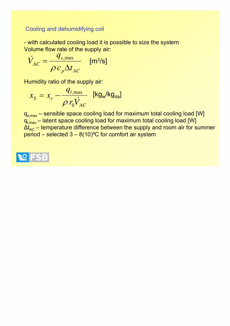
- with calculated cooling load it is possible to size the system
Volume flow rate of the supply air:
AC p
s
AC t c
q
V Δ= ρ
max,&[m
3
/s]
Humidity ratio of the supply air:
AC
lr S
V r
q x x
&0
max,
ρ −= [kgw/kgda]
qs,max – sensible space cooling load for maximum total cooling load [W]
ql,max – latent space cooling load for maximum total cooling load [W]
Δt AC – temperature difference between the supply and room air for summer
period – selected 3 – 8(10)ºC for comfort air system
Cooling and dehumidifying coil

8/11/2019 05 Component Sizing
http://slidepdf.com/reader/full/05-component-sizing 13/67
Cooling and dehumidifying coil- cooling and dehumidification:
- temperature and humidity ratio decrease
1
2
h1-h
2
)hh(mQ a 2121 −=− &&
2’
[kW]
- the state point 2 determined graphically
- the theoretical point 2’ read from the
table for saturation line

8/11/2019 05 Component Sizing
http://slidepdf.com/reader/full/05-component-sizing 14/67
Cooling and dehumidifying coil
- coil sizing when sensible and latent cooling load is known:
F OACLT C C QQQQ &&&& ++= , [W]
- cooling down of outdoor air to the room temperature is calculated from:
)( ioOAOA hhV Q −= ρ &&
[W]
- including heating up of air by fan (sensible cooling):
F
AC T F
V pQ η
&
&
Δ
= [W]
- coil is selected from the producer’s catalogue.

8/11/2019 05 Component Sizing
http://slidepdf.com/reader/full/05-component-sizing 15/67
- water coil:Cooling and dehumidifying coil
- usually have aluminum fins on copper tubes, although copper fins on
copper tubes are also used.
- core tube outside diameters are up to 25 mm, with fins spaced 1.4 to 6.4mm apart. Tube spacing ranges from 15 to 75 mm on equilateral
(staggered) or rectangular (in-line) centers, depending on the width of
individual fins and on other performance considerations.

8/11/2019 05 Component Sizing
http://slidepdf.com/reader/full/05-component-sizing 16/67
- direct expansion (DX) coil:
Cooling and dehumidifying coil
- the TXV used to automatically regulate the rate of refrigerant liquid flow to
the coil in direct proportion to the evaporation rate of refrigerant liquid in
the coil, thereby maintaining optimum performance over a wide range ofconditions.
- to ensure reasonably uniform refrigerant distribution in multicircuit coils, a
distributor is placed between the TXV and coil inlets to divide the
refrigerant equally among the coil circuits.

8/11/2019 05 Component Sizing
http://slidepdf.com/reader/full/05-component-sizing 17/67
- DX coil:
- the refrigerants usually HFC-134a, HFC-404A, HFC-407A, HFC-407C or
HFC-410A
- evaporating temperatures > 0ºC
- the superheat at the coil suction outlet
is continually maintained within the usual
predetermined limits of 3 to 6 K.
- air temperature leaving the coil is
normally 7 to 10 K higher than evaporating
temperature.
Cooling and dehumidifying coil

8/11/2019 05 Component Sizing
http://slidepdf.com/reader/full/05-component-sizing 18/67
Ratings and performance
- Entering air dry-bulb temperature. 18 to 38°C
Entering air wet-bulb temperature: 15 to 30°C
- Air face velocity: 1 to 4 m/s
- Evaporator refrigerant saturation temperature: −1 to 13°C at coil suction
outlet
- Entering chilled water temperature: 2 to 18°C
- Water velocity: 0.3 to 2.4 m/s
- For cold ethylene glycol solution: 0.3 to 1.8 m/s, −18 to 32°C entering dry-
bulb temperature, 15 to 27°C entering wet-bulb temperature, 10 to 60%aqueous glycol concentration by mass.
Cooling and dehumidifying coil

8/11/2019 05 Component Sizing
http://slidepdf.com/reader/full/05-component-sizing 19/67
Ratings and performance (continued)
- air-side ratio of sensible to total heat removed by dehumidifying coils
varies in practice from about 0.6 to 1.0 (i.e., sensible heat is from 60 to
100% of the total, depending on the application).
- dehumidifying coils for comfort application are frequently selected in the
range of 2.0 to 2.5 m/s air face velocity (limited to a value that prevents
water carryover into the air ductwork).
- reftigerant duty would be 3 to 6 K superheat for an appropriate balance at
7°C saturated suction.
- for water coils, circuitry would operate at 1.2 m/s, 5.5°C inlet water, 6.7 K
rise.
Cooling and dehumidifying coil

8/11/2019 05 Component Sizing
http://slidepdf.com/reader/full/05-component-sizing 20/67
Humidifier
- humidifying load is the amount of water vapor required to be added to the
air by a humidifier so as to maintain a predetermined space relative
humidity. It depends primarily on the rate of natural infiltration or the
amount of outside air introduced by mechanical means.- other sources of moisture gain should also be considered. Space
(internal) moisture gains include the latent load from the occupants,
appliances, equipment, and products.
iwoioOAh m x xV V m ,inf )()( &&&& −−+= ρ [kg/s]
Internal moisture gains
- when outside air with low moisture content xo is introduced to the HVACsystem (winter), the supply air moisture content should be 4 to 8 g/kg
above that amount.

8/11/2019 05 Component Sizing
http://slidepdf.com/reader/full/05-component-sizing 21/67
1
2w
s
- liquid water:
- water vapor:
- humidification by injection of water (liquid or vapor):
2v
x2
) x x(mm aw 12 −= &&
12
12
x x
hht ch
dx
dh wwww
−
−===
) x x(mm av 12 −= &&
12
12
x x
hhh
dx
dh vv
−
−==
from the table
for saturated
vapor [kJ/kg]
Humidifier

8/11/2019 05 Component Sizing
http://slidepdf.com/reader/full/05-component-sizing 22/67
Humidifier
- water humidifier:
1. Atomizing humidifier
- centrifugal (high-speed spinning disk)- spray nozzles (compressed air, water pressure)
- ultrasonic vibrations
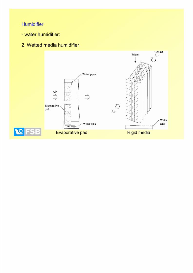
8/11/2019 05 Component Sizing
http://slidepdf.com/reader/full/05-component-sizing 23/67

8/11/2019 05 Component Sizing
http://slidepdf.com/reader/full/05-component-sizing 24/67
Humidifier
- water humidifier:
- usually designed at an air velocity between 2 and 4 m/s with respect to its
cross-sectional area at the water sprayers.
- length of humidifier section is usually 1.5 to 3 m.
- size of water droplets is up to 100 μm.
- total pressure loss of the airstream flowing through a humidifier depends
mainly on the configuration of the eliminators and the air velocity flowingthrough them. Usually it varies from 65 to 250 Pa, and typically it is 125
Pa.
- for humidification and evaporative cooling, the water-air ratio is usually
mw/ma=0.3 to 0.6. For a 1.5-m long air washer with mw/ma=0.45, that is, 0.5L/s of water per 1000 L/s of air, εsat = 0.85 to 0.9.

8/11/2019 05 Component Sizing
http://slidepdf.com/reader/full/05-component-sizing 25/67
Humidifier
- steam humidifier:
1. Direct steam injection
- with steam-jacketed manifolds

8/11/2019 05 Component Sizing
http://slidepdf.com/reader/full/05-component-sizing 26/67
Humidifier
- steam humidifier:
2. Self-contained, electrically heated
- electrode- or resistance type
8/11/2019 05 Component Sizing
http://slidepdf.com/reader/full/05-component-sizing 27/67
Humidifier
- steam humidifier:
- temperature of the ambient air or airstream in which moisture has been
added is approximately unchanged.
- for direct steam injection, the steam source is a central steam boiler at
low pressure.
- capacity is often controlled by a microprocessor-based controller by
modulating the valve pin of the control valve according to the signal of ahumidity sensor and, therefore, the steam flow rate.
- accuracy of humidity control of ± 5 to 7 % for on/off control and ± 3 to 5 %
for modulation control.
- has to be installed where the air can absorb the discharged vapor beforeit comes into contact with other components, such as coils or dampers.
Otherwise, condensation can occur in the duct.

8/11/2019 05 Component Sizing
http://slidepdf.com/reader/full/05-component-sizing 28/67
Fan
- the increase of air static pressure is created by the conversion of velocity
pressure to static pressure.
- fan total pressure rise is a true indication of energy imparted to the air
stream by the fan.
Centrifugal fan Axial fan

8/11/2019 05 Component Sizing
http://slidepdf.com/reader/full/05-component-sizing 29/67
Fan
Pressure drop in an air system
- total pressure drop:
LF T p p p Δ+Δ=Δ [Pa]
- friction losses are the result of the duct surface roughness:
2
2
wd L pF ρ λ =Δ [Pa]
- dynamic/local losses in system parts like AHU components, entries,
exits, dampers, elbows, T-junctions...:
2
2w
p L ρ
ζ =Δ [Pa]

8/11/2019 05 Component Sizing
http://slidepdf.com/reader/full/05-component-sizing 30/67
- fan – air handling component for supply and exhaust of ventilation air
EXT INT DIN STAT VENT p p p p p Δ+Δ≥Δ+Δ=Δ
REG MOT TRANSM VENT
VENT KL EL
pV P
η η η η ⋅⋅⋅
Δ=
&
- fan pressure:
- electric energy used for fan operation:
TOT p
VENT
c
pt
η ρ
Δ≈Δ
- heating up of the airflow by fan:
TOT
0,3-0,8
[ºC]
[W]
Fan

8/11/2019 05 Component Sizing
http://slidepdf.com/reader/full/05-component-sizing 31/67
Fan
- selection:
Pressure-volume flow operating characteristics. Selecting a fan to
provide the required volume flow rate and total pressure loss for an air
system or a ventilating system is of prime importance. An undersized fanresults in an uncontrolled indoor environment. An oversized fan wastes
energy and money.
Fan capacity modulation. A variable-air-volume system operates at a
reduced volume flow rate during part-load operation. Effective andeconomical fan capacity modulation is an important factor that affects the
operation of an air system.
Fan efficiency. Fan efficiency is closely related to the energy use of an air
system. Fans should be selected so that they can operate at highefficiency during as much of their operation time as possible.

8/11/2019 05 Component Sizing
http://slidepdf.com/reader/full/05-component-sizing 32/67
Fan
- selection (continued):
Sound power level. Most commercial and public buildings and many
industrial applications need a quiet indoor environment. Fans are the major
source of noise in an air system. Usually, the higher the fan total efficiency,the lower the sound power level of the selected fan. High-frequency sound
is more easily attenuated than low-frequency sound.
Airflow direction. In many applications, a straight-through or in-line flow
occupies less space and simplifies layout.
Initial cost . The initial cost of the fan modulation device, sound attenuator,
and space occupied by a particular type of fan, in addition to the cost of the
fan itself, should be considered.

8/11/2019 05 Component Sizing
http://slidepdf.com/reader/full/05-component-sizing 33/67
Fan
- fan is selected to meet
the requirements of the
system.
- selection is performedfrom the manufacturers’
tabular or graphic data.
- optimum selection
range is the zone of the peak efficiency.

8/11/2019 05 Component Sizing
http://slidepdf.com/reader/full/05-component-sizing 34/67
Fan
- commercial chart for the
fan selection – example
- fan pressure characteristics
have to fit the system pressurecharacteristic
- the total system must be
evaluated and the flow
requirements, resistances, andsystem effect factors at the
fan inlet and outlet must be
known.
- ducts should be connected
to a fan with canvas or other flexible material.
- sound power level data should
be obtained by the manufacturer

8/11/2019 05 Component Sizing
http://slidepdf.com/reader/full/05-component-sizing 35/67
Automatic control
- automatic control in the HVAC is used for:
- providing the thermal comfort or other conditions necessary for
the production process
- protection from unnecessary system failures or damages- operation control (on/off, modulating) and selection of parameters
by users
- HVAC system usually includes the control of:
- temperature- humidity
- pressure
- flow rate

8/11/2019 05 Component Sizing
http://slidepdf.com/reader/full/05-component-sizing 36/67
Automatic control
- control action:
1. Two-position (on/off, low/high)
- typical example – thermostat that starts and stops a device
- controller differential in two-position control action, is thedifference between a setting at which the controller operates to
one position and a setting at which it operates to the other.
2. Floating action
- controller can perform only two operations- moving the controlleddevice toward either its open or closed position, usually at a
constant rate.
- neutral zone between the two positions allows the controlled
device to stop at any position when the controlled variable is withinthe differential of
the controller.

8/11/2019 05 Component Sizing
http://slidepdf.com/reader/full/05-component-sizing 37/67
Automatic control
- control action (continued):
3. Modulating
- output of the controller can vary infinitely over the range of the
controller.- 3 typical modes:
a) Proportional (P)
- controlled device is positioned proportionally in response
to changes in the controlled variable.- output of the controller is proportional to the difference
between the sensed value, the controlled variable, and its
set point.

8/11/2019 05 Component Sizing
http://slidepdf.com/reader/full/05-component-sizing 38/67
Automatic control
b) Proportional-Integral (PI)
- adding another component to the control action thateliminates the offset typical of proportional control.
- increases stability, and eliminates offset, giving greater
control accuracy. PI control can also improve energy
efficiency in HVAC applications.
c) Proportional-Integral-Derivative (PID)
- control with a derivative term added to the controller that
varies with the value of the derivative of the error.
- faster response and greater stability, but more sensitiveto noisy signals and harder to tune than a PI controller.

8/11/2019 05 Component Sizing
http://slidepdf.com/reader/full/05-component-sizing 39/67
Automatic control
- control action (continued):
4. Fuzzy logic
- an alternative to traditional control algorithms.
- controller uses a series of “if-then” rules that emulates the way ahuman operator might control the process.
- “fuzzy” element is introduced when the functions overlap and the
room temperature is, for example, 70% high and 30% OK.
- example:
IF the room temperature is high AND the rate of change is
decreasing, THEN increase cooling a little.
or
IF the room temperature is high AND the rate of change is
increasing, THEN increase cooling a lot.

8/11/2019 05 Component Sizing
http://slidepdf.com/reader/full/05-component-sizing 40/67
Automatic control
- sensors:
- devices that respond to a change in the controlled variable. This signal is
sent to the controller.
- Temperature sensors
- Humidity sensors
- Pressure transmitters and transducers
- Flow rate sensors
- IAQ sensors (CO, CO2,...)
- Power sensors and transmission

8/11/2019 05 Component Sizing
http://slidepdf.com/reader/full/05-component-sizing 41/67
Automatic control - HVAC
Fan control:
- most efficient way to change the output of a fan is to change its speed.
- variable-frequency drives are widely used.
- axial fans can be controlled by varying the pitch of the blade.
- dampers and ducting can simply bypass some of the air from the supply
side of the fan to the return side. Bypassing does not change the output of
the fan, but it can allow the fan to accommodate flow variations in the
distribution system without fan instability.

8/11/2019 05 Component Sizing
http://slidepdf.com/reader/full/05-component-sizing 42/67
Automatic control - HVAC
Fan control:
- Differential static-pressure control is used to pressurize a building or
space relative to adjacent spaces or the outside. Typical applications
include clean rooms (positive pressure to prevent infiltration), laboratories
(positive or negative, depending on use), and various manufacturingprocesses, such as spray-painting rooms.
- pressure controller usually modulates dampers in the supply duct to
maintain the desired pressure as exhaust volumes change.
- method for control of the return fan requires measuring the space andoutside static pressures.
- location for measuring inside static
pressure must be selected away from
doors and openings to the outside,
away from elevator lobbies, and,when using a sensor, in a large
representative area shielded from
drafts.

8/11/2019 05 Component Sizing
http://slidepdf.com/reader/full/05-component-sizing 43/67
Automatic control - HVAC
Fan control:
- Duct static-pressure control for variable air volume (VAV) and other
terminal systems maintains a static pressure at a measurement point. The
most common application for static-pressure control is fan output control in
VAV systems.
- multiple static sensors are required when more than one branch duct
runs from the supply fan. The sensor with the highest static requirement
controls the fan.

8/11/2019 05 Component Sizing
http://slidepdf.com/reader/full/05-component-sizing 44/67
Automatic control - HVAC
Economizer cycle control:
- reduces cooling costs when outside conditions are suitable, that is, when
outside air is cool enough to be used as a cooling medium.
- if outside air is below a high-temperature limit, typically 18°C, the return,
exhaust, and outside air dampers modulate to maintain a ventilation
cooling set point, typically 13 to 16°C.
- when the outside air temperature exceeds the high-temperature limit set
point, the outside air damper is closed to a fixed minimum and the exhaust
and return air dampers close and open, respectively.- in enthalpy economizer control, the high-temperature limit interlock
system of the economizer cycle is replaced to further reduce energy costs
when latent loads are significant.
- possible warm-up with no
outside air and night cooldown
(if outside air conditions are
acceptable) with 100% outside air

8/11/2019 05 Component Sizing
http://slidepdf.com/reader/full/05-component-sizing 45/67
Automatic control - HVAC
Cooling coil control:
1. Chilled water coil
- controlled by two- or three-way valves, that are usually closed to prevent
cooling when the fan is off. The valve typically modulates in response to
coil air discharge temperature or space temperature.
COOLING COOLING
CHILLED-WATER CHILLED-WATER CHILLED-WATER CHILLED-WATER

8/11/2019 05 Component Sizing
http://slidepdf.com/reader/full/05-component-sizing 46/67
Automatic control - HVAC
Cooling coil control:
2. DX coil
- controlled by solenoid valves in the refrigerant liquid line. Face and
bypass dampers are not recommended because they permit ice to form on
the coil when airflow is reduced. Control can be improved by using two or
more stages.
- modulating control (uncommon) can be achieved using a variable-
suction-pressure controller.
Two-position Modulating
A t ti t l HVAC

8/11/2019 05 Component Sizing
http://slidepdf.com/reader/full/05-component-sizing 47/67
Automatic control - HVAC
Heating coil control:- coils that are not subject to freezing can be controlled by simple two- or
three-way modulating valves.
- valve is controlled by coil discharge air temperature or by space
temperature. Valves are set to open to allow heating if control power fails.
- heating coils in central air-handling units preheat, reheat, or heat,
depending on the climate and the amount of minimum outside air needed.
- hot-water coils must maintain a minimum water velocity in the tubes (on
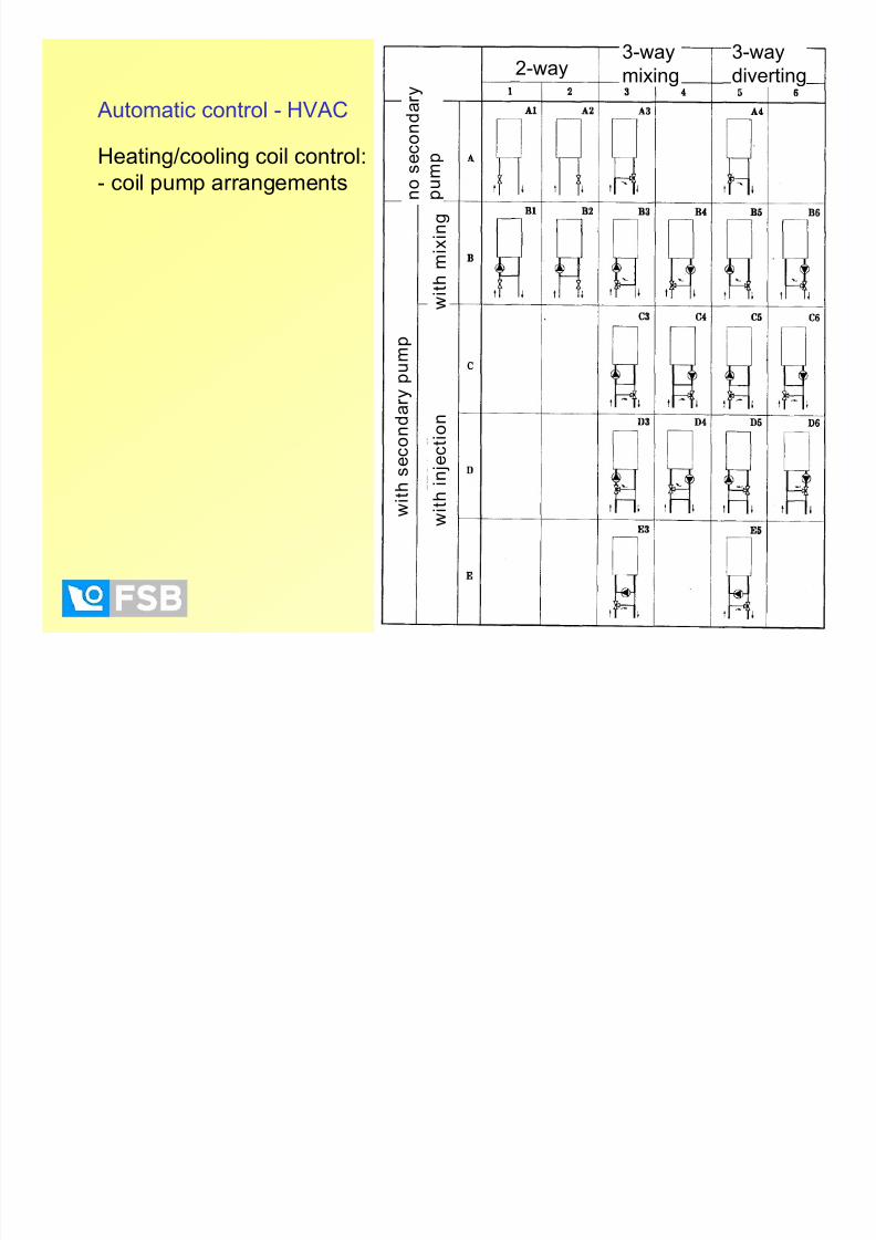
the order of 0.9 m/s) to prevent freezing (coil pump is common).
- in the conventional primary/secondary arrangement, the coil
pump and the pumps feeding the
coil are hydraulically independent.
It results in constant flow through
the coil and with constant flow
through the primary loop if a three-
way valve is used.

8/11/2019 05 Component Sizing
http://slidepdf.com/reader/full/05-component-sizing 48/67
Automatic control - HVAC
Heating coil control:
- the coil pump can be piped in series (A) with the primary pumps when the
three-way valve is open to the coil. In this case, flow through the coil will be
relatively constant, but can rise and fall depending on the differential
pressure available from primary pumps.
- the coil pump can be also piped in
parallel (B) with the primary pumps.
This design has the advantage that
hot-water flow can be achieved
through the coil even if either the
primary pump or coil pump fails.
Primary pump must be sized for the
pressure drop of the coil at this highflow rate.
(A) (B)
2-way3-way
mixing
3-way
diverting
8/11/2019 05 Component Sizing
http://slidepdf.com/reader/full/05-component-sizing 49/67
Automatic control - HVAC
Heating/cooling coil control:
- coil pump arrangements
mixing diverting
n o s e c o n
d a r y
p u m p
w i t h
s e c o n d a r y p u
m p
w i t h m i x i n g
w i t h i
n j e c t i o n

8/11/2019 05 Component Sizing
http://slidepdf.com/reader/full/05-component-sizing 50/67
Automatic control - HVAC
Humidity control:
- based on the output of a humidity sensor located either in the space or in
the return air duct.
- Dehumidification. One way is to override the control of the cooling coil.
The temperature of the coil is lowered until sufficient moisture is removed
from the supply air to maintain the humidity set point. Reheat coil may be
required to maintain the space temperature if the moisture removal
process results in too low a supply air temperature.

8/11/2019 05 Component Sizing
http://slidepdf.com/reader/full/05-component-sizing 51/67
Automatic control - HVAC
Humidity control:
- Dehumidification. If water condensing out of the airstream freezes on
the coil surface, airflow is restricted and, in severe cases, may be shut off.
The practical limit is about 5°C dew point on the coil surface. This results in
a relative humidity of about 30% at a space temperature of 24°C, which is
adequate for most commercial applications. When lower humidity is
needed, a chemical dehumidifier (desiccant-based) is required. Other way
is to use sprayed-coil dehumidifiers, but the problem is the cost of
maintenance, reheat, and removalof solid deposits on the coil.

8/11/2019 05 Component Sizing
http://slidepdf.com/reader/full/05-component-sizing 52/67
Automatic control - HVAC
Humidity control:
- Dehumidification. Desiccant-based dehumidifier can lower space
humidity below that possible with cooling/dehumidifying coils. This device
adsorbs moisture using silica gel or a similar material. For continuous
operation, heat is added to regenerate the material.

8/11/2019 05 Component Sizing
http://slidepdf.com/reader/full/05-component-sizing 53/67
Automatic control - HVAC
Humidity control:
- Humidification. A space or return air humidity sensor provides the
necessary signal for the controller. A humidity sensor in the duct should be
used to minimize moisture carryover or condensation in the duct. Usually,
the aim is to maintain design minimum humidity during the heating season.
Steam jet humidifier

8/11/2019 05 Component Sizing
http://slidepdf.com/reader/full/05-component-sizing 54/67
Automatic control - HVAC
Outside air control:
- provides ventilation air, space pressurization (exfiltration), and makeup
air for exhaust fans.
Fixed minimum outside air control with return-exhaust fan

8/11/2019 05 Component Sizing
http://slidepdf.com/reader/full/05-component-sizing 55/67
Automatic control - HVAC
Terminal units control:
- Reheat terminals. Use a single constant-volume fan system that serves
multiple zones. All delivered air is cooled to satisfy the greatest zone
cooling load. Air delivered to other zones is then reheated with heating
coils (hot water, steam, electric) in individual zone ducts.
- Throttling VAV terminal. A damper in the inlet controls the flow of
supply air. As the temperature in the space drops below the set point, the
damper begins to close and reduce the flow of air to the space. When the
airflow reaches the minimum limit,
the valve on the reheat coil begins
to open.

8/11/2019 05 Component Sizing
http://slidepdf.com/reader/full/05-component-sizing 56/67
Automatic control - HVAC
Terminal units control:
- Series fan-powered VAV terminal unit. An integral fan supplies a
constant volume of air to the space. When the space is occupied, the fan
runs constantly to provide a constant volume of air to the space. The fan
can draw air from the return plenum to compensate for the reduced supply
air. As the temperature in the space decreases below the set point, the
supply air damper begins to close and the fan draws more air from the
return plenum. When the supply air reaches its minimum level, the valve to
the reheat coil begins to open.

8/11/2019 05 Component Sizing
http://slidepdf.com/reader/full/05-component-sizing 57/67
Automatic control - HVAC
Terminal units control:
- Mixing box terminal. Have inlet dampers on the heating and cooling
supply ducts. These dampers are interlinked to operate in opposite
directions, and space thermostat positions the dampers through an
actuator to mix warm and cool supply air. By the VAV system, the airflow
controller controls the volume damper.
Dual-duct CAV mixing box
Dual-duct VAV mixing box
Automatic control - HVAC

8/11/2019 05 Component Sizing
http://slidepdf.com/reader/full/05-component-sizing 58/67
Terminal units control:
- example of throttling VAV terminal:
dpM
+ -
AIRFLOW AIRFLOW
-- AIRFLOW CHANGE AIRFLOW CHANGE
-- DETECTION AT TRANSDUCERDETECTION AT TRANSDUCER
-- REACTION OF CONTROLLERREACTION OF CONTROLLER
-- SIGNAL TO ACTUATORSIGNAL TO ACTUATOR
-- CORRECTION OF DAMPERCORRECTION OF DAMPER
BLADE POSITIONBLADE POSITION
-- AIRFLOW CORRECTED AIRFLOW CORRECTED
Automatic control - HVAC

8/11/2019 05 Component Sizing
http://slidepdf.com/reader/full/05-component-sizing 59/67
TVMTVM -- Dual Duct UnitDual Duct UnitM
M
dpw
+ -
dpw
+ -
Vcold
V w a r m
Vtotal
Room Temp: 22°C20°C Terminal units control:
- example of dual-duct VAV mixing box

8/11/2019 05 Component Sizing
http://slidepdf.com/reader/full/05-component-sizing 60/67
dp
d P = r e q u i r e d
v a l u e
Reference Pressure
Room Pressure
Automatic control - HVAC
Terminal units control:
- example of laboratory room pressure control: (1)

8/11/2019 05 Component Sizing
http://slidepdf.com/reader/full/05-component-sizing 61/67
Automatic control - HVAC
Terminal units control:
- example of laboratory room pressure control: (2)
dp
V to VV to Vminmin
//maxmax
d P = 0 P a
Actuator Actuator running timerunning time
minmin maxmax
~~150 s150 s
Reference Pressure
Room Pressure
A i l HVAC

8/11/2019 05 Component Sizing
http://slidepdf.com/reader/full/05-component-sizing 62/67
Automatic control - HVAC
Terminal units control:
- example of laboratory room pressure control: (3)
dp
d P > > r e q u i r e d
v a l u e
V =V = undefinedundefined
Reference Pressure
Room Pressure
Actuator Actuator running timerunning time
minmin maxmax
~~150 s150 s
A t ti t l HVAC

8/11/2019 05 Component Sizing
http://slidepdf.com/reader/full/05-component-sizing 63/67
Mas ter
S la ve
V + dp
c o n t r o l
s i g na l
C o n t r o l s i g
na l s la ve ≙ ac t ua l
va l ue s u p p l y a i r
S U P P L YS U P P L Y E X H A US
T E X H A US
T
Reference
Pressure
Room Pressure
Automatic control - HVAC
Terminal units control:
- example of laboratory room pressure control: (4)
Correct solution
A t ti t l HVAC

8/11/2019 05 Component Sizing
http://slidepdf.com/reader/full/05-component-sizing 64/67
Automatic control - HVAC
Control of systems:
- example of heating, cooling and humidifying HVAC system
Task. Control of temperature during the heating and cooling season and
control of humidity during the heating season. System operates with 100%outside air. AHU consists of the fan, the heating coil, the cooling coil, the
reheat coil and the water humidifier. System is single-duct, single-zone,
constant air volume (CAV). Water distribution system is with variable flow.
Control. Performed with three control loops.First control loop controls the (pre)heat coil operation by maintaining the
dew-point temperature constant. Temperature sensor (16), behind the
humidifier, sends signal to the PI controller (R1). Depending on the
temperature change, the controller R1 moves the valve drive, thus
changing the coil capacity according to the PI characteristic.
Automatic control - HVAC
Control of systems:
l f h ti li d h idif i HVAC t

8/11/2019 05 Component Sizing
http://slidepdf.com/reader/full/05-component-sizing 65/67
- example of heating, cooling and humidifying HVAC system
Automatic control HVAC

8/11/2019 05 Component Sizing
http://slidepdf.com/reader/full/05-component-sizing 66/67
Automatic control - HVAC
Control (continued).
Second control loop controls the cooling coil and the reheat coil operation
by maintaining the set point of the space temperature. Room temperature
sensor (12) measures the change of room temperature in dependance with
the outdoor air temperature. The outdoor air temperature is measured withthe duct sensor (1). The PI controller (R2) compares values of the two
temperatures. When the outside temperature increases, R2 closes the
valve (14), thus reducing the water flow through the reheat coil. Valves on
the reheat coil and the cooling coil water supply operate in a sequence –when the valve (14) closes completely, the valve (7) on the cooling coil
water supply starts to open.
Third control loop controls the humidifier operation. There is the two-
position hygrostat (21) in the return duct, that limits minimum andmaximum humidity. The hygrostat starts or stops the water pump in the
humidifier.
Automatic control HVAC

8/11/2019 05 Component Sizing
http://slidepdf.com/reader/full/05-component-sizing 67/67
Automatic control - HVAC
System protection.
Freeze protection is performed with low-limit temperature sensor (9). When
temperature behind the preheat coil is below 5ºC, the supply and the return
fan stop, the air dampers close, the valve on the preheat coil water supply
fully opens, the pump of the preheat coil starts and the humidifier pumpstops.
Control of pressure drop on the filter is performed by the differential
pressure sensor. Differential pressure sensors on the fans react in the
case of low-flow/no-flow and stop the fans, close the valves and thedampers and stop the circulating pumps.
Fire protection is performed with stopping the fans and closing all air
dampers.