Embed Size (px)
Citation preview
05 - 1NASA’s Goddard Space Flight Center
Systems Engineering
Mike Pryzby
Swales Aerospace
August 16-17, 2005
05 - 2NASA’s Goddard Space Flight Center
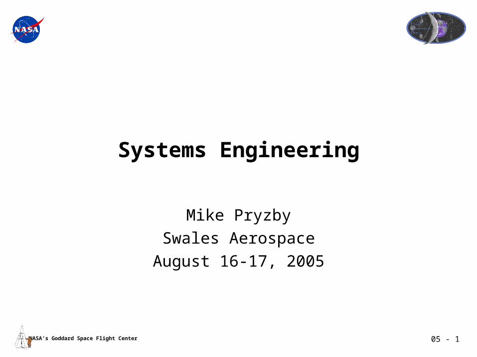
LRO Systems TeamMartin Houghton
Mission Systems Engineer
Michael PryzbyOrbiter Systems Engineer
Charles Wilderman
HW / SW Systems
Eric HolmesGN&C Systems
Giulio RosanovaMechanical
Systems
Phil LuersElectrical Systems
Rich SaylorGround Systems
Mike XapsosRadiation Engineer
Chris LorentsonContamination
Engineer
Nick VirmaniMfgr Engineer
Pilar JoyMaterials Engineer
Subsystem Leads
Lydia LeeSystems Reliability
Engineer
J. Simpson - ACS
C. Zakrzwski - Prop
Q. Nguyen - C&DH
J. Soloff - Comm.
M. Blau - Flight S/W
T. Spitzer - Power
C. Baker - Thermal R. Kinder - Harness
R. Saylor - Ground System
G. Casto - Structures
M. Hersh - Mechanisms
M. Beckman - Flight Dynamics
Ken DeilyMission Success
Systems Engineer
Mission Requirements Document (MRD)Systems ConceptRequirements Management
Concept of Operations
Reliability Analysis(FTA,FMEA, RBD, etc.)
Radiation Environment Assessment
Contamination Control Plan
Level 3 RequirementsSubsystem Spec & Verification PlansComponent SpecsICDs
Software ArchitectureS/W ResourcesSoftware ICDs
GN&C ArchitectureMechanismsDeployment Sys
Mechanical ICDs
Parts ReviewParts Use / Applicability
Database
Material ReviewMaterials Use /
Applicability Database
T. AjluniJ. Brannen
Arlin BartelsPayload Systems Manager
Joanne BakerI&T Engineer
I&T Plan Electrical Sys. SpecElectrical ICDs
R. Kinder
J. BakerL.HartzM. Reden
Tom JonesLaunch Vehicle Manager
LV ICD
05 - 3NASA’s Goddard Space Flight Center
LRO Systems Engineering Implementation Approach
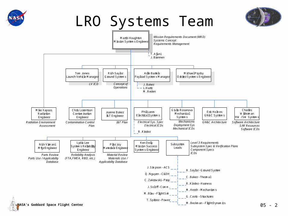
• SE is integrated into project as defined in our SEMP in accordance with GPR 7120.5 and tailored to reflect the successful approach taken by the core LRO team on past missions
• Key SE documents include; SEMP, Golden Rules, MRD & Siblings including Electrical, Mechanical, Thermal, and Pointing specifications, Allocations and Con Ops documents
Requirements ID & Mgmt- Level 1 Reqs, Min Mission Reqs
-Mostly Driven by Science- Top Down Hierarchy
- Reqs Flow, Doc Tree, WBS, Product Structure, Team Org
-Database utilized to track reqs flow, owner, verification
Architecture & Design- What the End Item looks like
- Flight and Ground Elements, Hardware, Software Block Diagrams, Operations Team
-Special Accommodations for Verification & Test
- Design for testability
Operations Concept Development- How the End Item is used
-Flight and Ground Elements, Hardware, Software, Operations Team
- How the End Item can be verified & tested on the ground- Test Points, GSE impacts on Architecture and Design
The Three Major Functions Must Lead to a Balanced Design that isConsistent with Project Cost, Schedule and Risk
Project Objectives Met,Ready for Operations
• SE activities defined by phase in our SEMP, phase A&B presented today• Evidence of our SE process is the content of this SRR
- Gold used by subsystems as requirements at L2/L3. Compliance matrix in process, due at PDR

05 - 4NASA’s Goddard Space Flight Center
Phase A Plans and ActivitiesLRO SEMP (431-PLAN-000005) System Engineering Lifecycle Activities Matrix
All Completed Preliminary Analysis - Phase A
Understanding the Objectives
- Understand and define Level 1 science requirements; Identify full and minimum mission reqs- 1st draft of Level 1 reqs for review at MDR- Validate Level 1 requirement and show flowdown to Level 2 requirements at MD
Operations Concept Development
- Identify and define LRO Mission Phases- Complete preliminary draft version of LRO Operation Concept Document
Architecture & Design Development
- Review LRO ORDT Report & previous concept studies- Identify key LRO design drivers & perform trade studies of various implementation design concepts- Define architecture design concept and balance with reqs and ops concept
Requirements Identification & Management
- Define draft Level 2 MRD reqs & demonstrate flowdown & traceability to Level 1 reqs at MDR- Detailed walkthrough of MRD Level 2 reqs traceability and assignment at SRR- Initial entry of MRD Level 2 reqs into DOORS database for mgmt and tracking- Define initial LRO Doc Tree, detailing subsystem reqs documentation structure & responsibility
Validation & Verification
- Perform initial trade studies and fold into initial system architecture design concept- Demonstrate MRD Level 2 reqs traceability to Level 1 reqs and to implementation design concept at SRR
Interfaces & ICDs - Begin initial discussions across instrument and subsystem lines on interface design concepts as part of initial architecture design baseline effort- Identify proposed ICD documents within LRO Document Tree
Mission Environments
- Complete initial radiation environment assessment and document in draft radiation white paper- Distribute contamination questionnaire to Instr, establish contamination working group, and complete draft contamination assessment- Define initial flight operational & test environments in Systems Verif & Envi Def document
Technical Resource Budget Tracking
- Establish formulation resource allocations as part of architecture design concept investigations- Baseline resource allocations at end of Phase A within SCR allocation margins- Bring resource allocations under CM at beginning of Phase B
Risk Management - Establish Risk Management Plan & Procedures & identify, classify, & report initial risk items- Begin initial fault tree analysis and reliability block diagrams and use to optimize design concept
System Milestone Reviews
- Hold Mission Design Retreat (MDR) to review Level 1 reqs and initial design concept- Hold System Reqs retreat (SRR) for detailed walkthrough of Level 2 MRD reqs and demonstrate flowdown & traceability to Level 1 reqs- Hold SRR/SCR for external review team- acts as review milestone for progression Phase B
Configuration Management &
Documentation
- Define LRO document tree and define subject, when due, and who responsible for each document
System Engineering Management Plan
- Complete draft SEMP and plans for Phase A definition of “single system design” concept- Update SEMP for Phase B activity plans to “design the right system”

05 - 5NASA’s Goddard Space Flight Center
Phase B Plans and Activities
LRO SEMP (431-PLAN-000005) System Engineering Lifecycle Activities Matrix Black –done, ◘Green – In progress
System Definition - Phase B
Understanding the Objectives
- Level 1 Science Reqs competed & signed off by NASA HQ; Includes minimum mission reqs- Track any changes to Level 1 reqs (changes req NASA HQ approval)
- Refine LRO Mission Phases definitions and LRO Operation Concept DocumentOperations Concept
Development
Architecture & Design
Development ◘- CM block diagram of LRO architecture design concept - Begin preliminary system and subsystem design process- Begin conceptual breadboard design process; use breadboards as testbeds and for interface testing across ss for risk reduction
Requirements Identification & Management
- Define draft Level 2 MRD reqs & demonstrate flowdown & traceability to Level 1 reqs at MDR- Detailed walkthrough of MRD Level 2 reqs traceability and assignment at SRR- Initial entry of MRD Level 2 reqs into DOORS database for mgmt and tracking- Define initial LRO Doc Tree, detailing subsystem reqs documentation structure & responsibility
Validation &
Verification ◘- Update MRD Level 2 reqs with verification information and use process to check validity of reqs
Interfaces & ICDs - Baseline and release initial documents and ICDs on LRO Document Tree
Mission
Environments◘- Update contamination assessment and complete draft Contamination Control Plan- Begin evaluation and tracking of parts and materials for use in identified flight environment- Update flight operational & test environments in Systems Verif & Envi Def document
Technical Resource Budget Tracking
- Bring resource allocations under CM at beginning of Phase B within appropriate margins- Track and control resource allocations to complete Phase B within PDR margin allocations
Risk Management ◘ - Complete initial FMEA of preliminary design concept and fold results back into design- Update fault tree analysis and reliability block diagrams & use to further optimize design concept- Ongoing identification, classification, & reporting of risk items per Risk Mgmt Plan & Procedures
System Milestone
Reviews ◘- Hold subsystem peer reviews and PDRs to review Level 3 reqs and initial design concepts- Hold Mission PDR for external review team- acts as review milestone for progression Phase C
Configuration Management &
Documentation
- Initiate CCB process to address changes to configured documents- Bring Level 1 Reqs, MRD Level 2 Reqs, and Level 3 Subsystem spec under CM
System Engineering
Management Plan ◘- Update SEMP for Phase C Design activity plans to ensure system is “implemented right”
05 - 6NASA’s Goddard Space Flight Center
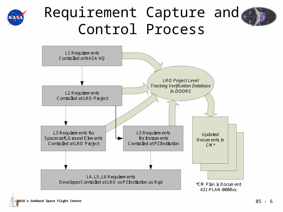
Requirement Capture and Control Process
L1 RequirementsControlled at NASA HQ
L2 RequirementsControlled at LRO Project
L3 Requirements forSpacecraft, Ground Elements
Controlled at LRO Project
L3 Requirementsfor Instruments
Controlled at PI Institution
L4, L5, L6 RequirementsDeveloper Controlled at LRO or PI Institution as Rqd
LRO Project LevelTracking Verification Database
In DOORS
Updated Documents in
CM*
*CM Plan is Document431-PLAN-0000xx

05 - 7NASA’s Goddard Space Flight Center
Review Process• Peer Reviews discipline driven, ingrained as an
institutional process at GSFC and our PI institutions• Project mandated peer reviews by SE and
management as deemed necessary– Examples include; FPGA’s, LROC Optical Design,
PDE Architecture
• Peer Review Process in accordance with GPR 8700.6A and LRO Peer Review Plan.
– SE attends and assigns actions as warranted– Project mandated/schedules as necessary, part of GSFC
process across all project elements– Team comprised of technical experts, internal and external as
required– Desire to keep review team through project lifecycle– Contested RFAs tracked in Project Action Item database
• PDR, CDR, PER, PSR etc content defined in our SE plan and controlled by LRO IIRT Review Plan (431-PLAN-000007)
TOPIC
Spacecraft & Ground System
Subsystem Peer Reviews
Phase
A/B
Phase
C/D
S/C Mechanical Sy stems 8/5/05 9/21/05
Thermal Sy stem 9/15/05
GN&C 8/5/05 9/15/05
Propulsion Module 5/5/05 3/22/06
Propulsion Tank 3/10/06
Pow er 8/5/05 9/13/05
C&DH 9/5/05 9/22/05
FLT S/W 11/5/05 11/4/05
Communication
Ground netw orks
Ground Data Sy stem/MOC
Div iner 8/25/05
LROC 8/1/05
LOLA
CRaTER
LAMP 6/17/05
LEND
PDE detail design options and
reliability assessment
38569
FPGA Implementations (all
subsy stems using FPGAs)
A/R A/R
SSR implementation options
preliminary design decision rev iew &
assessment. (C&DH, Flight Softw are)
38600 N/A
High Accuracy Tracking
implementation options and decision
rev iew . (Comm., GDS, LOLA)
38569 N/A
DATE/TIMEFRAME
Instrument Peer Reviews
Focused Technical Peer Reviews
???
05 - 8NASA’s Goddard Space Flight Center
Validation and Verification
• Validation process includes use of DOORS to insure no orphan requirements and proper traceability and flow down
• Verification is part our CM process and a mandatory section of each requirements document
• Verification matrix using DOORS database will include the following fields– Ownership to identify which individual is responsible for verifying this
requirement, as well as those others with a significant effort in the verification activities.
– Verification method; Inspection / Analysis / Demonstration / Test– Description of type of test, if needed– Verification Documentation to show where the requirement is verified– Verification Result Summary
• Mission Verification Plan will define overall process and plan for completion.
05 - 9NASA’s Goddard Space Flight Center
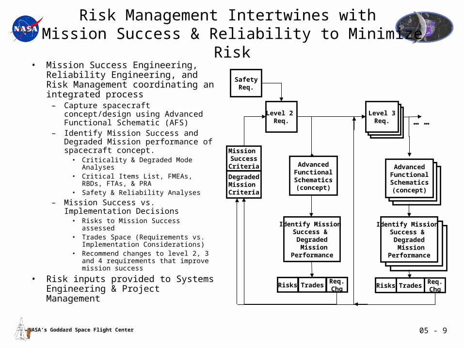
Risk Management Intertwines with Mission Success & Reliability to Minimize Risk
• Mission Success Engineering, Reliability Engineering, and Risk Management coordinating an integrated process
– Capture spacecraft concept/design using Advanced Functional Schematic (AFS)
– Identify Mission Success and Degraded Mission performance of spacecraft concept.
• Criticality & Degraded Mode Analyses• Critical Items List, FMEAs, RBDs,
FTAs, & PRA• Safety & Reliability Analyses
– Mission Success vs. Implementation Decisions
• Risks to Mission Success assessed• Trades Space (Requirements vs.
Implementation Considerations)• Recommend changes to level 2, 3 and 4
requirements that improve mission success
• Risk inputs provided to Systems Engineering & Project Management
Level 2 Req.
DegradedMission Criteria
SafetyReq.
Mission SuccessCriteria
Identify Mission Success & Degraded Mission
Performance
Risks TradesReq.Chg
Level 3Req.
AdvancedFunctionalSchematics(concept)
Risks TradesReq.Chg
……
AdvancedFunctionalSchematics(concept)
Identify Mission Success & Degraded Mission
Performance
05 - 10NASA’s Goddard Space Flight Center
LRO - PSE Reliability Prediction WorksheetOutput Module A
Designator Part Description & Type Part Number Manufacturer QualityBase Failure Notes
Critical Total Rate (FR)Critical CktBeing UsedCrit. Ckt Being
Ckt (N1)Used (N2) (Q) FRxN1xQ FRxN2xQ Used
C3, C5, C7, C10, C700, C1000, C4, C6, C8, C12, C13, C23, C34, C35, C43, C51, C53, C54, C55, C56, C14, C15, C16, C17, C18, C19, C20, C21, C22, C24, C25, C26, C27, C28, C29, C30, C31, C32, C33, C62, C63, C64, C65, C66, C67, C68, C69, C70, C71, C72, C73, C74
Cap, Ceramic, Chip, 0.010 uF, 25V, SR0805X7R103Presidio Components
56 60 1 6.3400E-13 3.5504E-11 3.8040E-11 ##### #####Obtained FR from the Manufacturer.
npC37, C38 Cap, Ceramic, Chip, 10 uF, 50V, 10% SR0405BX106K2S2Presidio Components
2 2 1 6.3400E-13 1.2680E-12 1.2680E-12 ##### 0.0001%Obtained FR from the Manufacturer.
C44, C45, C46, C47, C48, C49, C52, C50, C84
Cap, Ceramic, Chip, 0.10 uF, 50V, 10% SR0805X7R104Presidio Components
9 9 1 6.3400E-13 5.7060E-12 5.7060E-12 ##### #####Obtained FR from the Manufacturer.
C59 Cap., Fixed, Tantalum, Solid, ER, 22 uF, 20V, 10% CWR06J C226KCA 1 1 0.01 7.0000E-10 7.0000E-12 7.0000E-12 0.0010% 0.0007% Grade-1
C81Cap., Fixed, Tantalum, Solid, Low ESR, 100 uF, 16V, 10%
T495X107K016AS (562)
1 1 0.03 7.0000E-10 2.1000E-11 2.1000E-11 ##### #####Commercial. Goddard screening to FR Level: S
C82 Cap., Fixed, Cer. Dielectric, 1.0 UF, 50V, 10%M123A02BXB105KC
1 1 0.1 8.6000E-10 8.6000E-11 8.6000E-11 0.0117% ##### Grade-2, FR Level: C
C83Cap., Fixed, Tantalum, Solid, Low ESR, 220 uF, 6.3V, 10%
T495X227K006AS (562)
1 1 0.03 7.0000E-10 2.1000E-11 2.1000E-11 ##### #####Commercial. Goddard screening to FR Level: S
C200, C201, C202, C204, C205, C206, C208, C209, C210, C212, C213, C214, C220, C221, C222, C224, C225, C226, C228, C229, C230, C232, C233, C234, C236, C237, C238, C240, C241, C242, C244, C245, C246, C248, C249, C250, C252, C253, C254
Cap, Multi Layer, Fixed, Unencap, Ceramic Dielectric, 0.1 uF, 100V, 10%
CDR35BX104BKUS 27 39 0.03 1.8000E-09 1.4580E-09 2.1060E-09 0.1980% ##### Grade-1, FR Level: S
C203, C207, C211 Cap, Tantalum, Non-Solid, 6.8 uF, 75V, 10% M39006/30-0826 3 3 0.3 1.1000E-09 9.9000E-10 9.9000E-10 0.1344% 0.1035% Grade-2, FR Level: P
C215, C223, C227, C231, C235, C239, C243, C247, C251, C255
Cap, Tantalum, Non-Solid, 3.3 uF, 75V, 10% M39006/30-0823 6 10 0.3 1.1000E-09 1.9800E-09 ####### ##### 0.3451% Grade-2, FR Level: P
C216, C217, C218, C219
Cap, Tantalum, Non-Solid, 110 uF, 75V, 93026-46KS 4 4 0.1 1.1000E-09 4.4000E-10 4.4000E-10 0.0597% #####Commercial. Goddard screening to FR Level: R
Quantity Total Failure % of Assembly
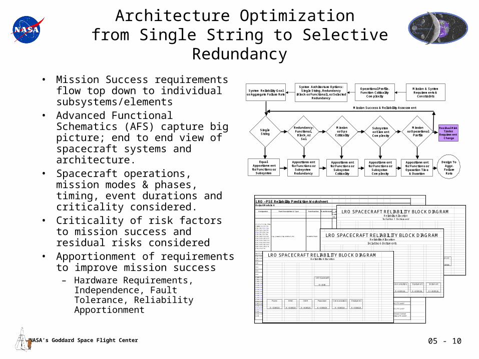
Architecture Optimization from Single String to Selective Redundancy
• Mission Success requirements flow top down to individual subsystems/elements
• Advanced Functional Schematics (AFS) capture big picture; end to end view of spacecraft systems and architecture.
• Spacecraft operations, mission modes & phases, timing, event durations and criticality considered.
• Criticality of risk factors to mission success and residual risks considered
• Apportionment of requirements to improve mission success
– Hardware Requirements, Independence, Fault Tolerance, Reliability Apportionment
LRO Spacecraft
R = 0.90
Power GN&C C&DH Propulsion Communications Deployment Instrument
R = 0.98506 R = 0.98506 R = 0.98506 R = 0.98506 R = 0.98506 R = 0.98506 R = 0.98506
Including 1 Instrument
LRO SPACECRAFT RELIABILITY BLOCK DIAGRAMReliability Allocation
LRO Spacecraft
R = 0.90
Power GN&C C&DH Propulsion Communications Deployment Instrument
R = 0.99126 R = 0.99126 R = 0.99126 R = 0.99126 R = 0.99126 R = 0.99126 R = 0.99126
Reliability AllocationIncluding 6 Instruments
LRO SPACECRAFT RELIABILITY BLOCK DIAGRAM
LRO Spacecraft
R = 0.90
Power GN&C C&DH Propulsion Communications Deployment
R = 0.98529 R = 0.98529 R = 0.98529 R = 0.98529 R = 0.98529 R = 0.98529
LRO SPACECRAFT RELIABILITY BLOCK DIAGRAMReliability Allocation
System Reliability Goalor Aggregate Failure Rate
Missionor Ops
Criticality
Subsystemor ElementComplexity
Operational Profile.Function Criticality
Complexity
System Architecture Options:Single String, Redundancy
(Block or Functional), or SelectedRedundancy
Equal Apportionment
for Functions orSubsystem
Redundancy:Functional,
Block, orSel.
Single String
Apportionmentfor Functions or
Subsystem Redundancy
Apportionmentfor Functions or
Subsystem Criticality
Missionor Operational
Profile
Residual RiskTrades
Requirement Change
Apportionmentfor Functions or
Subsystem Complexity
Apportionmentfor Functions orOperation Time
& Duration
Design ToAggr.
FailureRate
Mission Success & Reliability Assessment
Mission & SystemRequirements &
Constraints

05 - 11NASA’s Goddard Space Flight Center
Driving System Trades
TOPIC TRADE OUTCOMELV 2 Stage vs 3 Stage 7925H-9.5 ELVProp Mono Prop vs Bi Prop vs Hybrid Mono Prop
Primary StructureMaterial, configuration and tank accomodation
Honeycomb with Al facesheets for bus, composite face sheets for instrument deck, Configuration J
Solar Array Configuration Structure, shape and materialsSingle circular Ultra Flex array
Data Bus Architecture 1553, SpaceWire, CAN, Wireless, etc.
1553 for low speed, Spacewire for high speed interfaces
Data Storage SRR or Hard Drive Ongoing, due at PDRTiming USO in bus or LOLA instrument USO part of bus C&DHTracking S Band vs Other Ongoing, due at PDRComm System Ka vs X-Band Ka