Embed Size (px)
DESCRIPTION
IEEE paper on UWB
Citation preview
7/18/2019 04656862The Design of UWB Bandpass Filter-Combined Ultra-Wide Band Antenna
http://slidepdf.com/reader/full/04656862the-design-of-uwb-bandpass-filter-combined-ultra-wide-band-antenna 1/5
The Design of UWB Bandpass Filter-Combined Ultra-Wide Band
Antenna
Jung N. Lee, Jin H. Yoo, Ji H. Kim, Jong K. Park and Jin S. Kim
Department of Radio Wave Engineering, Hanbat National University, Korea
We have proposed a compact filter-combined ultra-wide band antenna for the use of DS-UWB low band or MB-OFDM lower threebands (3.1-5.2 GHz). The designed antenna has a microstrip-fed trapezoidal radiating patch, UWB band pass filter using the
dumbbell-shaped DGS (defected ground structure) and IDC (interdigital capacitor), two steps for impedance matching, and microstrip
feeding. Three kinds of prototypes (trapezoidal UWB antenna, UWB band pass filter, and the compact filter-combined ultra wideband
antenna) are fabricated and measured. The designed antenna has the figure-of-eight radiation pattern, wide bandwidth, and negligible
dispersion over the operating frequency band. Details of the proposed antenna design and the simulated and measured results are
presented and discussed.
Key word — UWB antenna, DS-UWB, MB-OFDM, UWB band pass filter, DGS, IDC, dispersion, group delay, path loss
I. I NTRODUCTION
ltra Wideband (UWB) is short distance radio
communication technology that can do high speed
communication with the speed more than 100 Mbps in 3
– 10 GHz frequency band. UWB enables wireless connectivity
with consistent high data rates across multiple devices and
PCs within the digital home and the office [1]. The UWB
systems can be divided into two categories: direct sequence
UWB (DS-UWB) and multiband orthogonal frequency
division multiplexing (MB-OFDM). The DS-UWB proposal
foresees two different carrier frequencies at 4.104 (low band:
3.1 to 5.15 GHz) and 8.208 GHz (high band: 5.825 to 10.6
GHz). Especially, DS-UWB using low band has been
developed as its first generation devices. By the MB-OFDM
format in 802.15.3a, the interval between 3.1 and 10.6 GHz is
divided into 14 sub-intervals. Each sub-interval corresponds to
one band of the MB-OFDM, with the bandwidth of 528 MHz[2, 3]. The MB-OFDM transceiver uses the low three bands
(centered at 3432, 3960, and 4488 MHz) as a mandatory
mode.
In UWB communications, in addition to achieving a good
return loss and radiation efficiency, the ultra wideband
antenna should be non-dispersive or dispersive in an
acceptable range. UWB antennas are the particularly
challenging aspect of UWB technology. The UWB antenna
requires an omni-directional, ultra-wideband, small size for
mobility, gain flatness and phase linearity for no distortion of
signal, and low-cost for manufacturing. Recently, many
researchers have developed UWB antennas operating in the
full UWB frequency band such as UWB patch antenna, planardiamond antenna, L-shaped metal-plate monopole antenna,
bowtie antenna, fractal dipole, Vivaldi antenna, and monopole
antenna [4-8]. A narrow band pass filter is integrated with the
patch antenna to serve as a transition between the CPW feed
and a microstrip patch antenna and also to cut the higher order
patch resonances [9].
In this paper, we will focus on the design of a compact
filter-combined ultra wideband antenna operating in the
frequency range of 3.1 to 5.2 GHz (DS-UWB low band or
MB-OFDM lower three bands). The designed compact filter-
combined ultra wideband antenna has a microstrip-fed
trapezoidal radiating patch, UWB band pass filter using the
dumbbell-shaped DGS (defected ground structure) and IDC
(interdigital capacitor), two steps for impedance matching, and
microstrip feeding. The design procedure is as follows. First,
we have designed a microstrip-fed trapezoidal UWB antennaoperating in a frequency range of 3.1-10.6 GHz [4, 5]. Second,
we have designed a UWB band pass filter having a pass band
of 3.1 to 5.2 GHz by using the DGS [10-12] and IDC [13]
structures. Finally, we have integrated the microstrip-fed
trapezoidal UWB antenna and the UWB band pass filter on
the single dielectric substrate to be used in the frequency range
of 3.1 to 5.2 GHz. Three kinds of prototypes (the microstrip-
fed trapezoidal UWB antenna, the UWB band pass filter, and
the compact filter-combined ultra wideband antenna) are
fabricated and measured. The dimension of the compact filter-
combined ultra wideband antenna is 30 mm by 41.2 mm. The
designed antenna exhibits a voltage standing wave ratio
(VSWR) of less than 2.0 over 3.1-5.2 GHz, and the figure-of-eight radiation patterns with gain from 2.3 to 3 dBi in a
frequency range of 3.1 to 5.2 GHz. The path loss (|S21|) and
the group delay are simulated and measured. The path loss is
almost constant across the frequency band (3.1 to 5.2 GHz)
and the group delay variation is less than 0.5 ns. Numerical
analysis using Ansoft HFSS [14] and measurement results are
presented.
II. A NTENNA DESIGN AND SIMULATED/MEASURED RESULTS
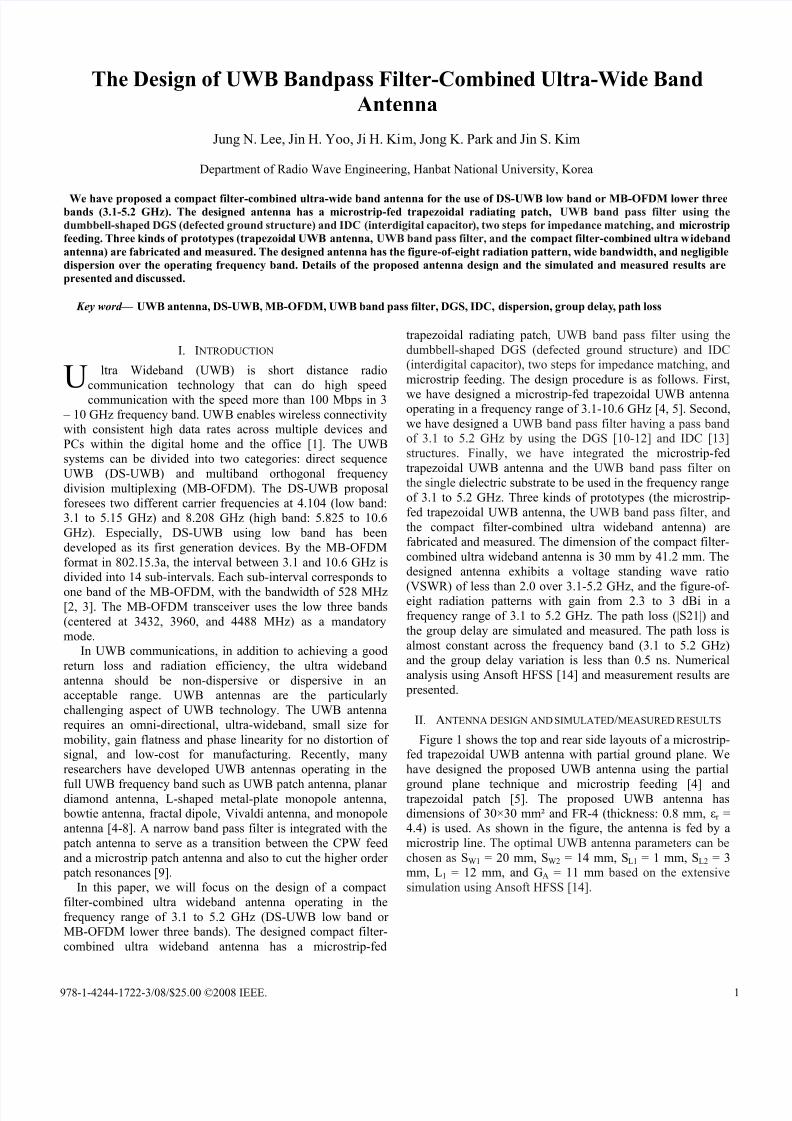
Figure 1 shows the top and rear side layouts of a microstrip-
fed trapezoidal UWB antenna with partial ground plane. We
have designed the proposed UWB antenna using the partial
ground plane technique and microstrip feeding [4] andtrapezoidal patch [5]. The proposed UWB antenna has
dimensions of 30×30 mm² and FR-4 (thickness: 0.8 mm, εr =
4.4) is used. As shown in the figure, the antenna is fed by a
microstrip line. The optimal UWB antenna parameters can be
chosen as SW1 = 20 mm, SW2 = 14 mm, SL1 = 1 mm, SL2 = 3
mm, L1 = 12 mm, and GA = 11 mm based on the extensive
simulation using Ansoft HFSS [14].
U
978-1-4244-1722-3/08/$25.00 ©2008 IEEE. 1
7/18/2019 04656862The Design of UWB Bandpass Filter-Combined Ultra-Wide Band Antenna
http://slidepdf.com/reader/full/04656862the-design-of-uwb-bandpass-filter-combined-ultra-wide-band-antenna 2/5
(a)
(b)
Fig. 1. Top and rear side layouts of a microstrip-fed trapezoidal UWB antenna
with partial ground plane.
Fig. 2. Measured and simulated results of the proposed UWB antenna.
The return loss (S11) of the UWB antenna was measured with
an Agilent Vector Network Analyzer (85107B) in an anechoic
chamber. Figure 2 shows the simulated and measured results
of the proposed UWB antenna. As shown in the figure, the
impedance bandwidth for S11 < -10 dB is 114 % (3.1-7.9
GHz). The simulated results have a reasonable agreement with
measured results.
(a)
(b)
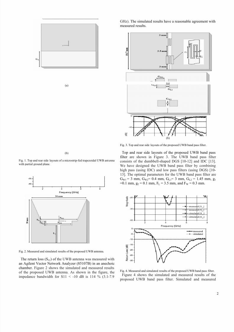
Fig. 3. Top and rear side layouts of the proposed UWB band pass filter.
Top and rear side layouts of the proposed UWB band pass
filter are shown in Figure 3. The UWB band pass filter
consists of the dumbbell-shaped DGS [10-12] and IDC [13].
We have designed the UWB band pass filter by combining
high pass (using IDC) and low pass filters (using DGS) [10-
13]. The optimal parameters for the UWB band pass filter areGW1 = 3 mm, GW2= 0.4 mm, GL1= 3 mm, GL2 = 1.45 mm, g1
=0.1 mm, g2 = 0.1 mm, FL = 3.5 mm, and FW = 0.3 mm.
Fig. 4. Measured and simulated results of the proposed UWB band pass filter.
Figure 4 shows the simulated and measured results of the
proposed UWB band pass filter. Simulated and measured
2
7/18/2019 04656862The Design of UWB Bandpass Filter-Combined Ultra-Wide Band Antenna
http://slidepdf.com/reader/full/04656862the-design-of-uwb-bandpass-filter-combined-ultra-wide-band-antenna 3/5
results are found to be in good agreement with each other. As
can be seen in the figure, the low and high cutoff frequencies
of the UWB band pass filter are 3 and 5 GHz, respectively. At
the central frequency of 4 GHz, the measured insertion and
return loss is 1.48 dB and 20 dB, respectively.
(a)
(b)
(c)
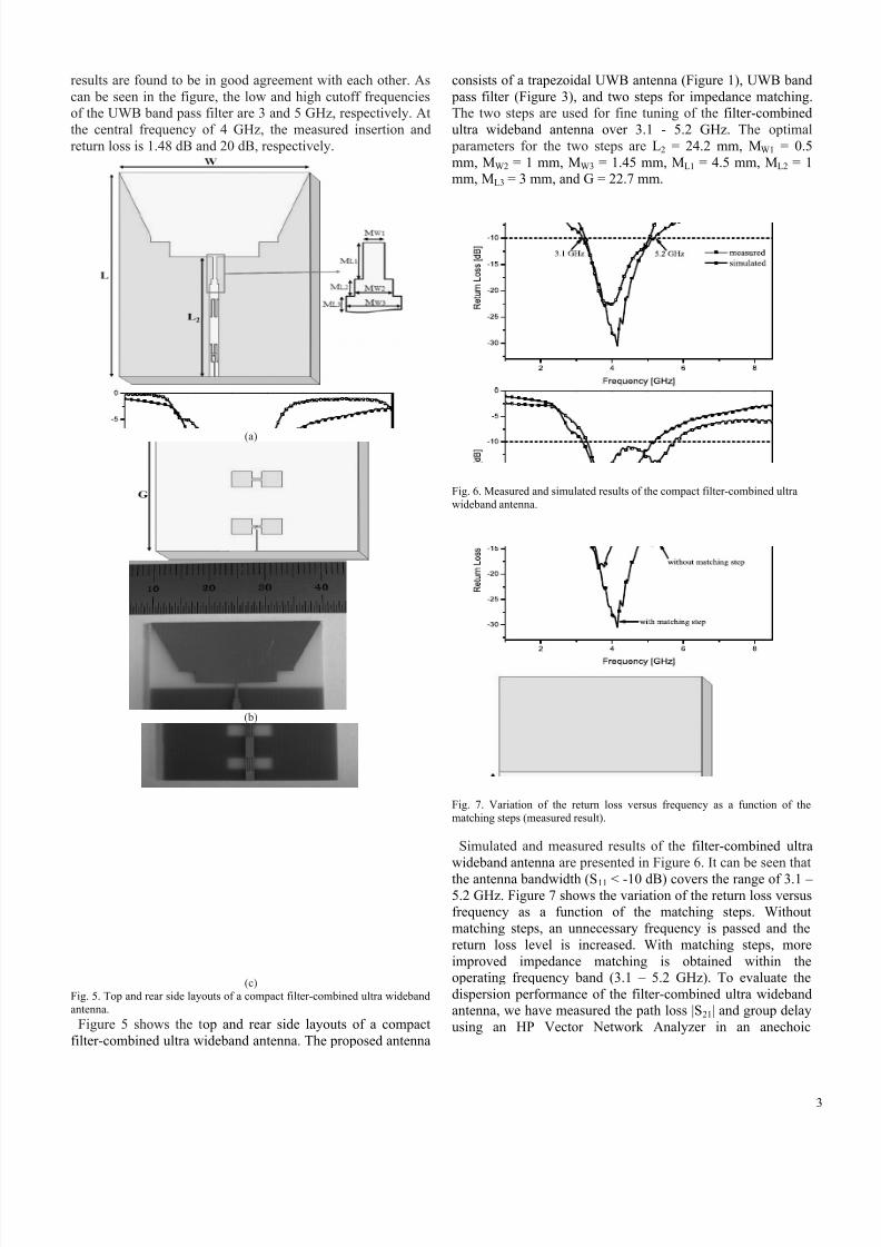
Fig. 5. Top and rear side layouts of a compact filter-combined ultra wideband
antenna.
Figure 5 shows the top and rear side layouts of a compact
filter-combined ultra wideband antenna. The proposed antenna
consists of a trapezoidal UWB antenna (Figure 1), UWB band
pass filter (Figure 3), and two steps for impedance matching.
The two steps are used for fine tuning of the filter-combined
ultra wideband antenna over 3.1 - 5.2 GHz. The optimal
parameters for the two steps are L2 = 24.2 mm, MW1 = 0.5
mm, MW2 = 1 mm, MW3 = 1.45 mm, ML1 = 4.5 mm, ML2 = 1
mm, ML3 = 3 mm, and G = 22.7 mm.
Fig. 6. Measured and simulated results of the compact filter-combined ultra
wideband antenna.
Fig. 7. Variation of the return loss versus frequency as a function of the
matching steps (measured result).
Simulated and measured results of the filter-combined ultra
wideband antenna are presented in Figure 6. It can be seen that
the antenna bandwidth (S11 < -10 dB) covers the range of 3.1 –5.2 GHz. Figure 7 shows the variation of the return loss versus
frequency as a function of the matching steps. Without
matching steps, an unnecessary frequency is passed and the
return loss level is increased. With matching steps, more
improved impedance matching is obtained within the
operating frequency band (3.1 – 5.2 GHz). To evaluate the
dispersion performance of the filter-combined ultra wideband
antenna, we have measured the path loss |S21| and group delay
using an HP Vector Network Analyzer in an anechoic
3
7/18/2019 04656862The Design of UWB Bandpass Filter-Combined Ultra-Wide Band Antenna
http://slidepdf.com/reader/full/04656862the-design-of-uwb-bandpass-filter-combined-ultra-wide-band-antenna 4/5
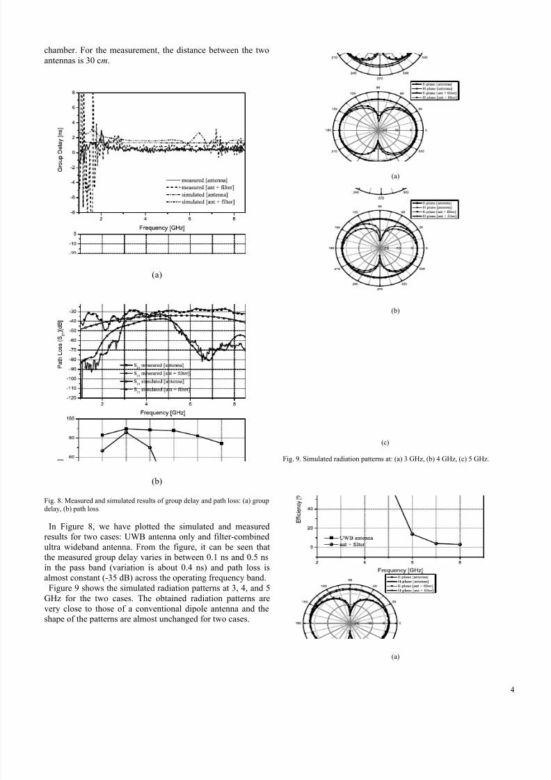
chamber. For the measurement, the distance between the two
antennas is 30 cm.
(a)
(b)
Fig. 8. Measured and simulated results of group delay and path loss: (a) groupdelay, (b) path loss.
In Figure 8, we have plotted the simulated and measured
results for two cases: UWB antenna only and filter-combined
ultra wideband antenna. From the figure, it can be seen thatthe measured group delay varies in between 0.1 ns and 0.5 ns
in the pass band (variation is about 0.4 ns) and path loss is
almost constant (-35 dB) across the operating frequency band.
Figure 9 shows the simulated radiation patterns at 3, 4, and 5
GHz for the two cases. The obtained radiation patterns are
very close to those of a conventional dipole antenna and the
shape of the patterns are almost unchanged for two cases.
(a)
(b)
(c)
Fig. 9. Simulated radiation patterns at: (a) 3 GHz, (b) 4 GHz, (c) 5 GHz.
(a)
4
7/18/2019 04656862The Design of UWB Bandpass Filter-Combined Ultra-Wide Band Antenna
http://slidepdf.com/reader/full/04656862the-design-of-uwb-bandpass-filter-combined-ultra-wide-band-antenna 5/5
(b)
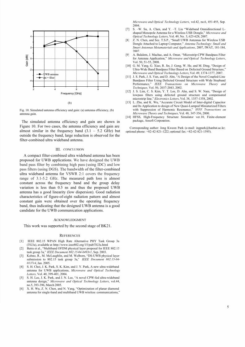
Fig. 10. Simulated antenna efficiency and gain: (a) antenna efficiency, (b)
antenna gain.
The simulated antenna efficiency and gain are shown inFigure 10. For two cases, the antenna efficiency and gain are
almost similar in the frequency band (3.1 – 5.2 GHz) but
outside the frequency band, large reduction is observed for the
filter-combined ultra wideband antenna.
III. CONCLUSION
A compact filter-combined ultra wideband antenna has been
proposed for UWB applications. We have designed the UWB
band pass filter by combining high pass (using IDC) and low
pass filters (using DGS). The bandwidth of the filter-combined
ultra wideband antenna for VSWR 2:1 covers the frequency
range of 3.1-5.2 GHz. The measured path loss is almost
constant across the frequency band and the group delayvariation is less than 0.5 ns and thus the proposed UWB
antenna has a good linearity (low dispersion). Good radiation
characteristics of figure-of-eight radiation pattern and almost
constant gain were obtained over the operating frequency
band, thus indicating that the designed UWB antenna is a good
candidate for the UWB communication applications.
ACKNOWLEDGMENT
This work was supported by the second stage of BK21.
R EFERENCES
[1]
IEEE 802.15 WPAN High Rate Alternative PHY Task Group 3a
(TG3a), available at http://www.ieee802.org/15/pub/TG3a.html[2]
Batra et al., “Multiband OFDM physical layer proposal for IEEE 802.15
task group 3a,” IEEE Document 802.15-04-0493r1, Sep. 2003.
[3]
Kohno, R., M. McLaughlin, and M. Welborn, “DS-UWB physical layersubmission to 802.15 task group 3a,” IEEE Document 802.15-04-
0137r4, Jan. 2005.[4]
S. H. Choi, J. K. Park, S. K. Kim, and J. Y. Park, A new ultra-wideband
antenna for UWB applications, Microwave and Optical Technology
Letters, Vol. 40, 399-401, 2004.[5]
S. H. Lee, J. K. Park, and J. N. Lee, “A novel CPW-fed ultra-wideband
antenna design,” Microwave and Optical Technology Letters, vol.44,
no.5, 393-396, March 2005.[6]
X. H. Wu, Z. N. Chen, and N. Yang, “Optimization of planar diamond
antenna for single-band and multiband UWB wireless communications,”
Microwave and Optical Technology Letters, vol.42, no.6, 451-455, Sep.
2004.[7]
S. –W. Su, A. Chen, and Y. –T. Liu “Wideband Omnidirectional L-
shaped Monopole Antenna for a Wireless USB Dongle,” Microwave andOptical Technology Letters, Vol. 49, No. 3, 625-628, 2007.
[8]
Z. N. Chen, and See. T.S.P., “Small UWB Antennas for Wireless USB
Dongle Attached to Laptop Computer,” Antenna Technology: Small and
Smart Antennas Metamaterials and Applications, 2007, IWAT, 181-184,
2007.[9]
A. Balalem, J. Machac, and A. Omar, “Microstrip-CPW Bandpass Filter
for Antenna Application,” Microwave and Optical Technology Letters ,
Vol. 50, 51-55, 2008.[10]
G. M. Yang, G. Xiao, R. Jin, J. Geng, W. He, and M. Ding, “Design of
Ultra-Wide Band Bandpass Filter Based on Defected Ground Structure,” Microwave and Optical Technology Letters, Vol. 49, 1374-1377, 2007.
[11]
J. S. Park, J. S. Yun, and D. Ahn, “A Design of the Novel Coupled-Line
Bandpass Filter Using Defected Ground Structure with Wide StopbandPerformance,” IEEE Transactions on Microwave Theory and
Techniques, Vol. 50, 2037-2043, 2002.[12]
J. S. Lim, C. S. Kim, Y. T. Lee, D. Ahn, and S. W. Nam, “Design of
lowpass filters using defected ground structure and compensated
microstrip line,” Electronics Letters, Vol. 38, 1357-1358, 2002.[13]
L. Zhu, and K. Wu, “Accurate Circuit Model of Inter-digital Capacitor
and Its Application to design of New Quasi-Lumped Miniaturized Filters
with Suppression of Harmonic Resonance,” IEEE Transactions on
Microwave Theory and Techniques, Vol. 48, 347-356, 2000.
[14]
HFSS, High-Frequency Structure Simulator ver.10, Finite-element
package, Ansoft Corporation.
Corresponding author: Jong Kweon Park (e-mail: [email protected];
optional phone: +82-42-821-1222; optional fax: +82-42-821-1595).
5