Embed Size (px)
Citation preview

Refer All Communications to the NearestIngersoll--Rand Office or Distributor.© Ingersoll--Rand Company 1998Printed in U.S.A.
04575544Form P7336Edition 1
INSTALLATION AND MAINTENANCE MANUALfor
SERIES TS900 TURBINE--POWERED STARTERS
TPD1781
IMPORTANT SAFETY INFORMATION ENCLOSED.READ THIS MANUAL BEFORE OPERATING TOOL.
FAILURE TO OBSERVE THE FOLLOWING WARNINGS COULD RESULT IN INJURY.• For safety, top performance, and maximum
durability of parts do not operate Series TS900Starters at air pressures over the pressure ratingstamped on the nameplate. Use supply lines ofadequate size as directed in the installationinstructions in this manual.
• Always turn off the air or gas supply anddisconnect the air or gas supply hose beforeinstalling, removing or adjusting any accessoryon this starter, or before performing anymaintenance on this starter.
• Series TS900 Starters are designed for gasoperation. They are not totally sealed in dynamicoperation since the exhaust must be vented orpiped away and there is a possibility of leakagearound the output shaft when rotating.
• Caution should be taken when operating thesestarters on gas because of the danger of fire,explosion, or inhalation. After assembling astarter, always test in accordance with theprocedures outlined in this manual. Neverinstall a reassembled starter that has not beentested in accordance with the procedures in thismanual.
• Operate this starter only when properly installedon the engine.
• Do not lubricate starters with flammable orvolatile liquids such as kerosene or jet fuel. Forpersonal protection, do not remove any labels.Replace any damaged label.
• Use only recommended Ingersoll--Randaccessories.
The use of other than genuine Ingersoll--Rand replacement parts may result in safety hazards, decrease starterperformance, and increased maintenance, and may invalidate all warranties.Ingersoll–Rand is not responsible for customermodification of starters for applications onwhich Ingersoll–Randwas notconsulted.Repairs should bemade only by authorized trained personnel. Consult your nearest Ingersoll–RandAuthorized Servicecenter.It is the responsibility of the employer to place the information in this manual into the hands of the operator.
2
WARNING LABEL IDENTIFICATION
FAILURE TO OBSERVE THE FOLLOWING WARNINGS COULD RESULT IN INJURY.
MODEL TS900 TURBINE--POWERED STARTER OPERATING GUIDELINES
Never exceed the Nameplate pressure rating.
Always release the start button immediately after the engine starts.
Whenever assembling the exhaust cover to the starter, be sure to add 15 ml of grade C3 turbine oil to the pipe plughole marked “oil here”
If the engine has not started after 30 seconds of ranking, refer to the engine maintenance guides for imformation onstarting, ignition, and fuel systems.
When using the starter for dynamic timing measurements, rest the starter for 2 minutes between 30 secondmeasuerments.
ST900--267--24 Strainer or equivalent is required for all starters used in GAS applacations.
WARNING
Always wear hearingprotection when testing thisstarter.
WARNING
Do not use damaged, frayedor deteriorated air hosesand fittings.
Always turn off the airsupply and disconnect theair supply hose beforeinstalling, removing oradjusting any accessory onthis starter, or beforeperforming any maintenanceon this starter.
WARNING
Always wear eye protectionwhen performing mainte-nance on this starter.
WARNING

3
CONTENTS
Page
Operation Guidelines 2. . . . . . . . . . . . . . . . . . . . . . . . . . . . . . . . . . . . . . . . . . . . . . . . . . . .
Installation 4. . . . . . . . . . . . . . . . . . . . . . . . . . . . . . . . . . . . . . . . . . . . . . . . . . . . . . . . . . . .
Mounting Dimensions 5--6. . . . . . . . . . . . . . . . . . . . . . . . . . . . . . . . . . . . . . . . . . . . . . . . .
Piping/Installation Drawings 7--8. . . . . . . . . . . . . . . . . . . . . . . . . . . . . . . . . . . . . . . . . . . .
How to Order 9. . . . . . . . . . . . . . . . . . . . . . . . . . . . . . . . . . . . . . . . . . . . . . . . . . . . . . . . . .
Detailed Illustrations 10--12. . . . . . . . . . . . . . . . . . . . . . . . . . . . . . . . . . . . . . . . . . . . . . . .
Parts Listing 13--14. . . . . . . . . . . . . . . . . . . . . . . . . . . . . . . . . . . . . . . . . . . . . . . . . . . . . . .
Motor Assembly 15. . . . . . . . . . . . . . . . . . . . . . . . . . . . . . . . . . . . . . . . . . . . . . . . . . . . . .
Disassembly 16--17. . . . . . . . . . . . . . . . . . . . . . . . . . . . . . . . . . . . . . . . . . . . . . . . . . . . . . .
Assembly 17--19. . . . . . . . . . . . . . . . . . . . . . . . . . . . . . . . . . . . . . . . . . . . . . . . . . . . . . . . .
Test and Inspection 19. . . . . . . . . . . . . . . . . . . . . . . . . . . . . . . . . . . . . . . . . . . . . . . . . . . .
Troubleshooting 20. . . . . . . . . . . . . . . . . . . . . . . . . . . . . . . . . . . . . . . . . . . . . . . . . . . . . . .
Maintenance Schedule 21. . . . . . . . . . . . . . . . . . . . . . . . . . . . . . . . . . . . . . . . . . . . . . . . . .
Index 22. . . . . . . . . . . . . . . . . . . . . . . . . . . . . . . . . . . . . . . . . . . . . . . . . . . . . . . . . . . . . . .

4
PLACING THE STARTER IN SERVICE
INSTALLATION
For maximum performance, read this manual priorto the installation or operation of Series TS900Turbine--Powered Starters.General Information1. All pipe connections to the starter must br
designed--to provide continuously leak proof joints.Piping the starter should not impose stress on thestarter as the result of operating vibration, thermalexpansion or unsupported weight.
2. All piping, hoses, fittings and components must beclean, free of weld splatter, and any contaminationthat can enter the starter.
3. The exhaust of the starter has a 90º housing for usein piping away the exhaust (ST700K--350). Refer toDwg. TPA1471 for instructions.
4. The installation of the starter must comply with allappropriate specifications; such as torquingthreaded fasteners and fittings, lubrication asinstalled and during operation, air (or gas) flow toand from the unit, cleanliness and safety.
5. It is required that a Strainer be installed in the inletline for each starter. Ingersoll--Rand offers 3 sizesof Strainers: ST900--267--24 for 1 inch lines,ST900--267--32 for 2 inch lines and ST900--267--64for 4 inch lines. These 300 mesh strainers provide50 micron filtration and offer significant protectionagainst supply line contaminates which coulddamage the turbine components. Replacementelements are ST900--266--24 for 1 inch,ST900--266--32 for 2 inch, and ST900--266--64 for 4inch lines.
6. All air (gas) line connections must be bubble tight.Ingersoll--Rand No. 5MB--441 sealant applied toclean threads will help assure a leak proof system.
7. In gas installations, all exhausts must be piped to asafer location. This applies to the exhaust from theRelief Valve and the Control Valve (5MBG--618 or150BMD--Z451B) as well as the starter exhaust.
8. If the supply air (gas) to the starter is at a higherpressure than that stamped on the nameplate of thestarter, a pressure regulator must be installed in thesupply line ahead of the relay valve. The pressuresetting of the regulator is to be the operatingpressure of the starter and not greater than thenameplate stamping. A relieving type regulator isrecommended. If this type is not available it isimportant to install a relief valve between theregulator and relay valve. The opening pressure of
the relief valve should be 15 psi. above theregulator setting.
9. The air supply lines between the relay valve, toecontrol valve, and starter should be as short and freeof fittings as practical.
10. The air supply lines should be arranged to providedrainage for condensation. This is especiallyimportant when the lines are long.
11. The starter, control components and air lines shouldbe arranged so that they are protected from heat,vibration and contamination.
12. Apply a film of Dextronr *II AutomaticTransmission fluid to the driving spline and mountthe starter using the Mounting Cap Screws. Tightenthe Mounting Cap Screws to 40--45 ft--lbs(54--61 Nm) torque.
13. Refer to Dwg. TPA1464 for torque and lubricationspecifications.
Barring Over the EngineThe rotor shaft has a 1/4” hex socket in the end that canbe used to rotate the engine shaft. This hex socket canbe accessed by removing the directional exhaust 1/4”NPT plug (31) form that housing to access the 1/4” hexsocket.Orientation of the StarterOrientation refers to the rotational location of thelubrication ports in the Drive Housing, the rotationallocation of the air (gas) inlet, and if used, the rotationallocation of the directional exhaust cover.It is recommended that the correct orientation beordered from the factory. If it is necessary to reorientthe unit in the field, refer to Dwg. TPA1462 and proceedas follows:1. To rotate the Drive Housing relative to the inlet:
a. Remove the Cap Screws (35) holding the DriveHousing (32) to the Gear Case.
b. Rotate the Drive Housing to the requiredposition. Do not remove the Drive Housingfrom the Gear Case (3).
c. Install the Cap Screws (35) and tighten to 28ft.--lbs. (38 Nm) torque.
2. To rotate the Directional Exhaust cover with respectto the inlet:a. Remove the Starter Assembly Cap Screws (6).b. Rotate the Exhaust Cover to it’s required
position. Do not remove the Cover from theMotor Housing or separate the Motor Housingand Gear Case
c. Reinstall the Cap Screws (6) and tighten themto 60 ft.--lbs. (81.4 Nm) torque in 20 ft--lb. (27Nm) increments.
* Registered trademark of Exxon Corp.

PLACING THE STARTER IN SERVICE
5
TPE_1020

PLACING THE STARTER IN SERVICE
6
TPE_1001

PLACING THE STARTER IN SERVICE
7
TPE_1002

PLACING THE STARTER IN SERVICE
8
TPE_1003

9
PLACING THE STARTER IN SERVICE
Series TS900 Turbine-Powered Starters are designed for air or gas operation in off-highway, marine and sta-tionary applications.
HOW TO ORDER A STARTER
PART NUMBER CODE
T S 9 9 9 G Z C D -- L E
EXHAUST
ROTATIONSHAFTFLANGE
RATIOCLUTCHARC OF ADMISSIONMODEL
TURBINE OR RECIPROCATING ENGINE
Model Supply Pressure Pinion DataSupply Pressurepsi/kPA Max No. of Teeth Diametral
PitchPitch
DiameterPA
TS999GZFA--L 90/620 24 20/30 1.2 30TS999GZCD--LE 90/620 16 20/30 .8 30
For different models or special applications, contact your nearest Ingersoll-Rand distributor or Ingersoll-Rand Engine Starting Systems, Box 8000, Southern Pines, NC 28387 (910) 692-8700

MAINTENANCE SECTION
10
TPE_1004

MAINTENANCE SECTION
11
TPE_1005
MAINTENANCE SECTION
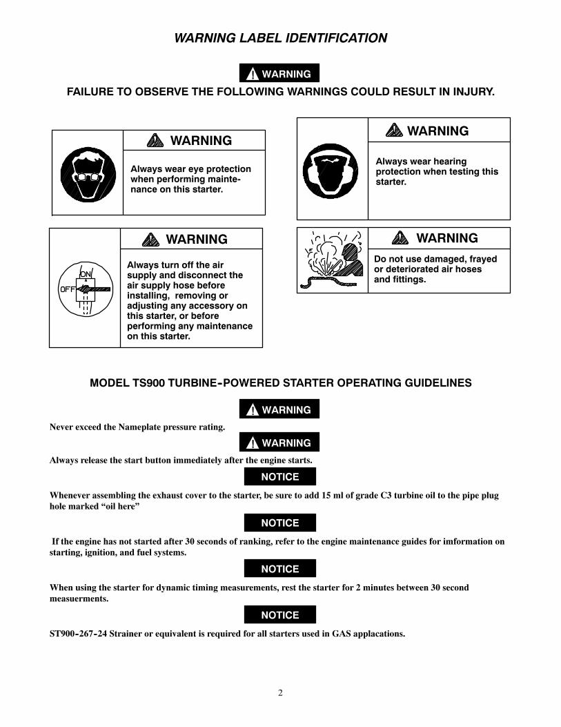
12
TPE_1006

MAINTENANCE SECTION
13
PARTNUMBERFORORDERING
PARTNUMBERFORORDERING
ExhaustKit
.............................
ST700--350
21Cap
Screw
..............................
TS700--25S
1DirectionalH
ousing
Exhaust
22Shaft(3)
................................
ST900--191
Cover
...............................
ST700--350
23Cap
Screw
..............................
R3F7
2ExhaustCoverSeal
.....................Y327--162
24Bearing
(1)..............................
TA--22
*Plug
...................................
ROH--377
25Fram
e..................................
TS900--A108
3GearCase...............................
ST900--372
26Spacer(3)...............................
ST900--91
4RearGearCaseO--ring....................
Y327--163
27Gear(3)................................
ST900--10
5FrontG
earCaseO--ring....................
Y327--158
28Bearing
(3)..............................
ST900--24
6StarterAssem
blyCap
Screw(4).............
ST900--2574
29Bearing
.................................
TS700--22
7Cap
ScrewWasher(4).....................
SS800--26
30Spacer..................................
TS700--20
MotorHousing
Assem
bly..................
ST900--A40
31Pipe
Plug
(2)............................
R0H
--377
8MotorHousing
...........................
ST900--40
32Drive
Housing
...........................
TS875--300
9InletFlangeKit(includesInletFlange,........
ST700--K166
33Seal....................................
TS700--54
Flange
MountingBoltsandLockWashers)
34Washer(8)..............................
TE223A
--415
*SightG
lass
...........................TS700--38
35Cap
Screw(8)...........................
SS800--744
10Housing
Plug
(2).......................04564563
36Splined
ShaftA
Model
....................
TS710A--13F
11Housing
Plug
InletB
oss.................04564530
36Splined
ShaftD
Model
....................
04612834
*Nam
eplate
..............................
ST900--301
37O--Ring.................................
Y327--123
*Nam
eplateScrew(4)......................
R4K
--302
38Snap
Ring...............................
TS700--16
12MotorAssem
bly
.........................
ST799R--A53A
39O--Ring.................................
Y327--046
12A
MotorO--RingSeal(2)....................
ST700--67
40ExhaustFlange
...........................
ST700--351
12B
Housing
O--RingSeal(2)...................
Y327--32
42Lockw
asher(6)..........................
854--58
13Snap
Ring...............................
SS875--366
43Cap
Screw(6)...........................
ST700--703
14RearBearing
............................
SS875--399
44Studs(6)................................
TS700--745
15Spacer..................................
SS875--367
45“C”Flange
..............................
04559464
16Clutch..................................
TS700--359
45“E”Flange
..............................
04559175
17Spacer..................................
TS700--368
46GearRing...............................
04334850
18FrontB
earing
............................
SS875--278
47GearFram
eBearing
.......................
T06--24
19ClutchHousing
..........................
TS875--14
*Tune--up
Kit.............................
TS700--TK1
20Drive
Shaft..............................
TS700--8S
*RebuildKit..............................
TS700--RM1
*Notillustrated.

14
MAINTENANCE SECTION
MOTOR ASSEMBLY
* THESE PARTS ONLY AVAILABLE AS AN ASSEMBLY (Dwg. TPD1778)

15
MAINTENANCE SECTIONAlways wear eye protection when operating orperforming any maintenance on this starter.Always turn off the air or gas supply and disconnectthe air or gas supply hose before installing, removingor adjusting any accessory on this starter or beforeperforming any maintenance on this starter.
LUBRICATIONEach time a Series TS900 Starter is disassembled formaintenance or repair, lubricate the starter as follows:1. Lubricate all o--rings with o--ring lubricant.2. Add 300 ml (approximately pint) of C32 Grade
Turbine Oil through the side plug hole in the MotorHousing (8)
3. Wipe both end splines of splined shaft withIngersoll--Rand No. 130 Grease.
4. Add 15 ml of C32 grade turbine oil at (31) plug inexhaust cover.
DISASSEMBLYGeneral Information1. Do not disassemble the Starter any further than
necessary to replace worn or damaged parts.2. When grasping a part in a vise, always use
copper--covered vice jaws to protect the surface ofthe part and help prevent distortion. This isparticularly true of threaded and die cast members.
3. Do not remove any part which is a press fit in or ona subassembly unless the removal of that part isnecessary for replacement or repairs.
4. Always have a complete set of seals and o--rings onhand before starting any overhaul of a Series TS900Turbine Starter. Never reuse old seals or o--rings.
5. Mark adjacent housings so they can be reassembledinto the same relative positions with adjacent centerpunch marks on the out side of the flanges on theexhaust cover (1), Motor housing (8), and GearCase (3). A quick drying marking pen can be usedas an alternative.
6. Do not press any bearing from a part unless youhave new bearings on hand for installation.Bearings are always damaged during the removalprocess.
Housing Exhaust Cover, Motor Assembly, andMotor Housing.1. If replacing the Motor Assembly (12), remove
Housing Plug (10) and drain the oil from thegearing before beginning disassembly of the Starter.Inspect the Magnetic Housing Plugs (10) for metalparticles. Very fine metal particles are normal.Remove particles and reinstall plugs. Largeparticles or chips are an indication of a problem. Ifapparent, disassemble Gear Case (3) and inspect.
2. Using an 8 mm Hex--head wrench, unscrew andremove the Starter Assembly Cap Screws (6) andWashers (7).
3. Pull the Housing Exhaust Cover (1) from theMotor Housing (8). To dislodge the HousingExhaust Cover, rotate it until the ears clear theMotor Housing. Using a plastic hammer, tap theears alternately until the Housing Exhaust Covercan be removed from the Motor Housing. Refer toDwg. TPD1782.
(Dwg. TPD1782)
4. To dissassemble the Housing Exhaust Elbow andcomponents. Refer to Dwg. TPD1773.
(Dwg. TPD1773)5. Tap the Motor Housing with a plastic hammer to
dislodge it from the Gear Case (3).
(Dwg. TPD1774)

16
MAINTENANCE SECTION6. Grasp the rear of the Motor Assembly (12) and pul
from the rear of the Motor Housing. If the MotorAssembly is difficult to remove, lightly, push themotor pinion which is in the front of the MotorAssembly toward the exhaust side of the MotorHousing in order to free the Motor Assembly.TheMotor Assembly (12) is replaced as a unit and notdisassembled in the field. Refer to Dwg. TPD1783.
(Dwg. TPD1783)
12A
12A
12B
12B
12
Drive Housing and Gear Case Disassembly1. Remove the 8 Hex Head Cap Screws (35) that hold
the two housings together. Refer toDwg. TPD1775.
(Dwg. TPD1775)
2. Using two pry bars on opposite sides of theassembly, carefully pry the two housings apart.
3. To remove the Splined Shaft (36) from the ClutchShaft (19), remove Snap Ring (38).
4. Using a 10 mm wrench remove the Cap Screw (21)from the Clutch Shaft.
5. Remove the clutch assembly from the Gear Case.The clutch assembly is replaced as a unit from theopposite side of the Gear Case and notdisassembled any further in the field.
(Dwg. TPD1776)
6. Remove the Planet Frame (25). Refer to Dwg. TPD1776.
7. Using a bearing puller remove the two Bearings(24) from the planet frame (25).
8. The two Gear Shaft Retaining Washers (23) can beremoved from the Planet Frame.
9. The three Planet Gear Shafts (22) can be pushedfrom the planet frame
This will free for removal the Planet Gears (27),the Bearing Spacers (26), and the Needle Rollers(28).
ASSEMBLYAssembly of the StarterGeneral1. Always press on the inner ring of a ball bearing
when installing the bearing on a shaft.2. Always press on the outer ring of a ball bearing
when pressing the bearing in a bearing recess.3. Whenever grasping a part in a vise, always use
leather--covered, copper--covered vise jaws toprotect the surface of the part and help preventdistortion. This is particularly true of threaded anddie cast parts.
4. Always clean every part, and wipe every part with athin oil film before installation.
5. Note the orientation markings that were placed onthe mating flanges before disassembly and assurethe assembled unit is arranged as beforedisassembly.

17
MAINTENANCE SECTION6. Coat all O--rings and the contact surface on their
mating parts with o--ring lubricant immediatelybefore assembling those parts.
7. When pressing parts together, assure that the partsare located firmly against a shoulder or otherwisepositioned as specified.
Assembly of the Directional Housing ExhaustCover1. Coat the Exhaust Cover Seal (2) with o--ring
lubricant and install in the groove in the DirectionalHousing Exhaust Cover (1).
2. Install Directional Housing Exhaust Cover on therear of the Motor Housing (8) in the desiredorientation and using a plastic hammer, tap theDirectional Housing Exhaust Cover until it seats.
3. Secure the Directional Housing Exhaust Cover onthe rear of the Motor Housing using the StarterAssembly Cap Screws (6) and Cap Screw Washers(7). Using an 8mm hex--head wrench, tighten eachCap Screw a little at a time to a final torque of 55ft--lb (74.5 Nm) in 20 ft--lb (27 Nm) increments.Refer to Dwg. TPD1782.
4. Lubricate Exhaust Adapter Seal (39) with o--ringlubricant and install in groove in Exhaust Flange.
Use LoctiteR 56747 **Pipe Sealant on all plugs.5. Place the starter in a vertical position with Exhaust
Elbow Plug (31) up. Pour 15 ml of C32 GradeTurbine Oil and replace Plug.
6. Install the bottom Housing Plug (10) with LoctiteR56747 and the Housing Plug Inlet Boss (11). Put theStarter on its side with the side plug hole upward.Add 300 ml (approximately pint) of C32 GradeTurbine Oil through the side plug hole in the MotorHousing (8).
Change oil annually or every 500 starts.Clutch Assembly
The Clutch should be replaced after 1500 starts.1. Press the Front Clutch Bearing (18) onto the Drive
Gear Shaft (20).2. Insert the Shaft Bearing Assembly into the Clutch
Housing (19). If necessary, tap into position with aplastic hammer using the correct adapter.
3. With the Clutch Shaft in a vertical position, insert insequence, Spacer (17) , the Clutch (16), and Spacer(15). For opposite rotation units (right hand orcounter clockwise starter rotation), reverse theclutch orientaion from that shown in Dwg.TPD1793.
** Registered trademark of Loctite Corporation
(Dwg. TPD1793)
4. Using a 28 mm maximum diameter Gear Shaftsupport which extends through the splined end ofthe Clutch Shaft, carefully press the Rear ClutchBearing (14) into place.
5. Install the Retaining Ring (13) into the groove inthe Clutch Shaft.
6. Press the Bearing onto the Clutch Shaft (20) so thatit seats against the shoulder on the shaft.
Gear Case Assembly1. Assemble Gear Shaft Retaining Washer (23) onto
end of Planet Frame opposite the driving dogs. Thecounterbored side of the Washer must be towardsthe Planet Frame.
2. Press Bearing (24) onto Planet Frame so that it seatsagainst the Washer.
3. Carefully slide Gear (27) onto the Planet Frame sothat the holes line up.
4. Remove the Shaft from the vise, holding it by theplain end, and position it so that the step on theopposite end lines up with the Retaining Washer onthe opposite side of the Planet Frame. Slide it intothe Planet Frame, through the Gear and through theopposite side of the Planet Frame. Tap lightly witha plastic hammer if necessary. Repeat thisprocedure for each Planet Gear.
5. Screw in 3 cap screws (23) to secure gears.

18
MAINTENANCE SECTION6. Press the Planet Frame Bearing (47) onto the Planet
Frame so that it seats against the frame.7. Press Shaft Seal (33) into the front of the Drive
Housing (32). The metal case of the Seal mustenter the housing first.
8. Place the Motor Housing Assembly in a verticalposition with the Gear Case end up. Assemble thePlanet Gear Frame by fitting the Bearing (24) intothe bore in the Motor Housing.
9. Assemble the O--ring (4) onto the Gear Case. (3)10. Carefully set the Gear Case down over the Planet
Frame Assembly and onto the Motor Housing.Rotate the Gear Case slightly as needed to engagethe Planet Gear Teeth into the internal Gear in theGear Case. Rotate the Gear Case onto the indicatedorientation and tap into position with a plastichammer.
11. Lay the assembly over its side and thread the StarterAssembly Capscrews (6) with Lockwashers (7)onto the four holes. Alternately tighten the screwsto 50 ft.--lb. (68 Nm) in 10--15 ft--lb. (16 Nm)increments.
12. Assemble the Clutch Assembly into the PlanetFrame. Make sure that the driving dogs on thePlanet Frame mesh with the driving dogs on theDrive Gear Shaft.
13. Insert the Screw (21) with Loctite 242 through theDrive Gear Shaft and thread onto the Planet Frame.Tighten to 90 ft.--lb. torque (122 Nm). For righthand rotation, hold the Clutch Shaft with a straptype wrench.
14. Assemble the O--ring (5) onto the Drive Housing(32).
15. Carefully lower the Drive Housing down over theClutch Assembly onto the face of the Gear Casebeing careful not to damage the top of the HousingSeal. After the seal has been positioned onto theClutch Shaft, the Drive Housing can be tapped ontoplace with a plastic hammer.
16. After positioning the Drive Housing to theorientation marks, thread the eight Capscrews (35)and Lockwashers (34) onto the tapped holes in theGear Case. Tighten the cap screws to 28 ft.--lb. (38Nm) torque.
17. Assemble the O--ring (37) onto the Splined Shaft(36). Carefully insert it into the Clutch Shaft. Tapit into place with a plastic hammer. Insert the SnapRing (38) into the Clutch Shaft (19).
Test And Inspection Procedure1. Turn the Splined Shaft by hand in the direction of
starter rotation. It should turn freely and easily.2. Turn the Shaft in the opposite direction. It will be
more difficult to turn; however, it should turnsmoothly with no binding. Turn the shaft through12 to 15 revolutions.
3. Confirm orientation by referring through topreviously placed markings or installation drawing.
4. Secure starter in a vise and apply 90 psi (6.2BAR/620kPa) pressure using a 3/8” (9mm) supplyline to the inlet of the motor. The starter should runsmoothly. Confirm that the Splined Shaft is turningin the correct direction. If applicable, confirm thatthe exhaust deflector returns to it’s normal positionafter the air is turned off.
5. With the starter immersed in a non--flammable,bubble--producing liquid, slowly apply 20 psi (1.38Bar/138 kPa) to the inlet of the motor for 30seconds. No bubbles should appear.

19
MAINTENANCE SECTION
TROUBLESHOOTING GUIDETrouble Probable Cause Solution
No air supply Check for blockage or damage to air supply lines ortank
Motor will not run Damaged Motor Assembly (12) Inspect Motor Assembly and power train and repairpower train or replace Motor Assembly if necessary
Foreign material in Motor and/orpiping
Remove Motor Assembly and piping and removethe blockage
Blocked exhaust system Remove Housing Exhaust Cover (1) and check forblockage
Defective Control or Relay Valve Replace Control Valve or Relay Valve
Loss of power Low air pressure to starter Check air supply
Restricted air supply line Check for blockage or damage to air lines
Relay Valve malfunctioning Clean or replace lines or Relay Valve. LubricateRelay Valve
Exhaust flow restricted Check for blockage or damaged piping. Clean orreplace piping. Check for dirt or foreign materialand clean or remove. Check for ice build--up. Meltice and reduce moisture build--up to Starter
Damaged Motor Assembly Replace Motor Assembly
Oil blowing out of exhaust Oil in air supply line Inspect air line and remove source of oil.
Splash Deflector Retaining Screw(31) or pipe plug missing.
Install Splash Deflector Retaining Screw or PipePlug.
Worn or damaged rotor seals orstatic O--rings
Replace static seals on outside of Motor or sendMotor to Ingersoll--Rand to be rebuilt.
Oil leaking from Gear Case Worn or damaged O--rings Replace O--rings
Loose joints Make sure that joints fit properly and StarterAssembly Cap Screws are tightened to 60 ft--lb (81Mn) torque. Make sure all seals and O--rings fit andseal properly at their perimeters. If they do notreplace with new seals and O--rings.
Excessive high speed operation Operate according to recommendations.
High number of start cycles Replace worn components
Loose or leaking Pipe Plugs (31)(11)
Tighten or replace Pipe plugs using Ingersoll--RandNo. SMB--441 Pipe Sealant.
Splash Deflector Retaining Screwor Pipe Plug missing.
Tighten Splash Deflector Retaining Screw orreplace Pipe Plug.
Air or Gase Leakage Loose joints Make sure that joints fit properly and StarterAssembly Cap Screws are tightened to 60 ft--lb (81Mn) torque. Make sure all seals and O--rings fit andseal properly at their perimeters. If they do notreplace with new seals and O--rings.
Excessive high--speed operation Operate according to recommendations.
High number of start cycles. Replace worn components.
Loose or leaking Pipe Plugs. Tighten or replace Pipe Plugs
Splash Deflector Retaining Screwloose or pipe plug missing
Tighten Splash Deflector Retaining Screw orreplace Pipe Plug.

20
MAINTENANCE SECTION
TS900 MAINTENANCE SCHEDULE
STARTS COMPONENTS RECOMMENDATION
500 C3 TURBINE OIL CHANGE
500 ALL EXTERNAL CAP SCREWS CHECK TORQUE
500 STRAINER CHECK ELEMENT
1000 C3 TURBINE OIL CHANGE CHANGE
1000 ALL EXTERNAL CAP SCREWS CHECK TORQUE
1000 STRAINER CHEC, ELEMENT
1500 C3 TURBINE OIL CHANGE
1500 ALL EXTERNAL CAP SCREWS CHECK TORQUE
1500 STRAINER CHECK ELEMENT
1500 CLUTCH, TS700--359 CHANGE
1500 REAR BEARING, SS875--399 CHANGE
1500 FRONT BEARING, SS875--278 CHANGE
1500 SEAL, TS700--54 CHANGE
1500 O--RING, Y327--158 CHANGE
1500 O--RING, Y327--123 CHANGE
1500 BEARING, TS700--22 CHANGE
2000 C3 TURBINE OIL CHANGE
2000 ALL EXTERNAL CAP SCREWS CHECK TORQUE
2000 STRAINER CHECK ELEMENT
2500 C3 TURBINE OIL CHANGE
2500 ALL EXTERNAL CAP SCREWS CHECK TORQUE
2500 STRAINER CHECK ELEMENT
3000 C3 TURBINE OIL CHANGE
3000 CLUTCH, TS700--359 CHANGE
3000 ALL EXTERNAL CAP SCREWS CHECK TORQUE
3000 STRAINER CHECK ELEMENT
3000 REAR BEARING, SS875--399 CHANGE
3000 FRONT BEARING, SS875--278 CHANGE
3000 SEAL, TS700--54 CHANGE
3000 O--RING, Y327--158 CHANGE
3000 O--RING, Y327--123 CHANGE
3000 BEARING, TS700--22 CHANGE
3500 C3 TURBINE OIL CHANGE
3500 ALL EXTERNAL CAP SCREWS CHECK TORQUE
3500 STRAINER CHECK ELEMENT

21
INDEX
Page
Operation Guidelines 2. . . . . . . . . . . . . . . . . . . . . . . . . . . . . . . . . . . . . . . . . . . . . . . . . . . .
A
Assembly of the Starter 17--19. . . . . . . . . . . . . . . . . . . . . . . . . . . . . . . . . . . . . . . . . . . . . .
B
Barring Over the Engine 4. . . . . . . . . . . . . . . . . . . . . . . . . . . . . . . . . . . . . . . . . . . . . . . . .
C
Clutch 17--19. . . . . . . . . . . . . . . . . . . . . . . . . . . . . . . . . . . . . . . . . . . . . . . . . . . . . . . . . . .
D
Detailed Illustrations 10--12. . . . . . . . . . . . . . . . . . . . . . . . . . . . . . . . . . . . . . . . . . . . . . . .
Dimensions of the Starter 5--6. . . . . . . . . . . . . . . . . . . . . . . . . . . . . . . . . . . . . . . . . . . . . .
Disassembly of Starter 16--17. . . . . . . . . . . . . . . . . . . . . . . . . . . . . . . . . . . . . . . . . . . . . . .
Drive Gear 17. . . . . . . . . . . . . . . . . . . . . . . . . . . . . . . . . . . . . . . . . . . . . . . . . . . . . . . . . . .
Drive Housing 17. . . . . . . . . . . . . . . . . . . . . . . . . . . . . . . . . . . . . . . . . . . . . . . . . . . . . . . .
G
Gear Case Assembly 18. . . . . . . . . . . . . . . . . . . . . . . . . . . . . . . . . . . . . . . . . . . . . . . . . . .
H
Housing Exhaust Cover 18. . . . . . . . . . . . . . . . . . . . . . . . . . . . . . . . . . . . . . . . . . . . . . . .
I
Installation of Starter 4. . . . . . . . . . . . . . . . . . . . . . . . . . . . . . . . . . . . . . . . . . . . . . . . . . . .
L
Lube and Torque Drawings 10. . . . . . . . . . . . . . . . . . . . . . . . . . . . . . . . . . . . . . . . . . . . .
Lubrication 16. . . . . . . . . . . . . . . . . . . . . . . . . . . . . . . . . . . . . . . . . . . . . . . . . . . . . . . . . .
M
Maintenance Schedule 21. . . . . . . . . . . . . . . . . . . . . . . . . . . . . . . . . . . . . . . . . . . . . . . . .
Motor Assembly. 18. . . . . . . . . . . . . . . . . . . . . . . . . . . . . . . . . . . . . . . . . . . . . . . . . . . . . .
Motor Assembly Drawings 15. . . . . . . . . . . . . . . . . . . . . . . . . . . . . . . . . . . . . . . . . . . . . .
O
Operation Guidelines 2. . . . . . . . . . . . . . . . . . . . . . . . . . . . . . . . . . . . . . . . . . . . . . . . . . . .
Ordering Information 9. . . . . . . . . . . . . . . . . . . . . . . . . . . . . . . . . . . . . . . . . . . . . . . . . . .
P
Parts Listing 13--14. . . . . . . . . . . . . . . . . . . . . . . . . . . . . . . . . . . . . . . . . . . . . . . . . . . . . . .
Piping/Installation Drawings 7--8. . . . . . . . . . . . . . . . . . . . . . . . . . . . . . . . . . . . . . . . . . . .
T
Test and Inspection 19. . . . . . . . . . . . . . . . . . . . . . . . . . . . . . . . . . . . . . . . . . . . . . . . . . . .
Troubleshooting 20. . . . . . . . . . . . . . . . . . . . . . . . . . . . . . . . . . . . . . . . . . . . . . . . . . . . . . .

22
NOTES


MAINTENANCE SECTION
24
PARTNUMBERFORORDERING
PARTNUMBERFORORDERING
ExhaustKit
.............................
ST700--350
12MotorAssem
bly
.........................
ST7990R--A53A
1DirectionalH
ousing
Exhaust
Cover
...............................
ST700--350
2ExhaustCoverSeal
.....................Y327--162
*Plug
...................................
ROH--377
3GearCase...............................
ST900--372
4RearGearCaseO--ring....................
Y327--163
5FrontG
earCaseO--ring....................
Y327--158
6StarterAssem
blyCap
Screw(4).............
ST900--2574
7Cap
ScrewWasher(4).....................
SS800--26
MotorHousing
Assem
bly..................
ST900--A40
8MotorHousing
...........................
ST900--40
9InletFlangeKit(includesInletFlange,........
ST700--K166
Flange
MountingBoltsandLockWashers)
*SightG
lass
...........................TS700--38
10Housing
Plug
(2).......................R2--227
11Housing
Plug
InletB
oss.................ROH--377
*Nam
eplate
..............................
ST900--301
*Nam
eplateScrew(4)......................
R4K
--302
*Notillustrated.
MAINTENANCE SECTION
25
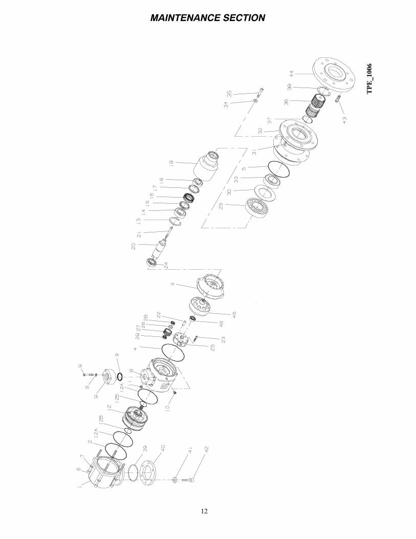
PARTNUMBERFORORDERING
PARTNUMBERFORORDERING
12A
CylinderO--RingSeal(2)..................
ST700--67
33Seal....................................
TS700--54
12B
Housing
O--RingSeal(2)...................
Q4032V75
34Washer(8)..............................
TE223A
--415
13Snap
Ring...............................
SS875--366
35Cap
Screw(8)...........................
SS800--744
14RearBearing
............................
SS875--399
36Splined
ShaftA
Model
....................
TS710--13A
15Spacer..................................
SS875--367
36Splined
ShaftB
Model
....................
TS710--13B
16Clutch..................................
TS700--359
36Splined
ShaftC
Model
....................
TS710--13C
17Spacer..................................
TS700--368
36Splined
ShaftD
Model
....................
TS710--13D
18FrontB
earing
............................
SS875--278
36Splined
ShaftE
Model.....................
TS700--18B
19ClutchHousing
..........................
TS875--14
36Splined
ShaftF
Model.....................
TS710--13F
20Drive
Shaft..............................
TS700--8S
36Splined
ShaftG
Model.....................
TS710--13G
21Cap
Screw
..............................
TS700--25S
36Splined
ShaftH
Model
....................
TS710--13H
22Shaft(3)
................................
ST700--191
37O--Ring.................................
Y327--123
23Spacer(2)...............................
ST700--364
38Snap
Ring...............................
TS700--16
24Bearing
(2)..............................
TA--22
39O--Ring.................................
Y327--046
25Fram
e40
ExhaustFlange
...........................
ST700--351
Aratio
..........................
TS700--108A
41WeldSleeve
.............................
ST700--352
Bratio
..........................
TS700--108B
42Lockw
ashers(6)..........................
854--58
26Spacer(6)...............................
ST700--364
43Cap
Screw(6)...........................
ST700--703
27Gear(3)
44Studs(6)................................
TS700--745
Aratio
..........................
TS700--10A
45BFlange
................................
TS700--300--B
Bratio
..........................
TS700--10B
45CFlange
................................
TS700--300--C
28Bearing
(3)..............................
ST700--363
45DFlange
................................
TS700--300--D
29Bearing
.................................
TS700--22
45EFlange
................................
TS700--300--E
30Spacer..................................
TS700--20
*Tune--up
Kit.............................
TS700--TK1
31Pipe
Plug
(2)............................
ROH--377
*RebuildKit..............................
TS700--RM1
32Drive
Housing
...........................
TS875--300
*Notillustrated.

MAINTENANCE SECTION
26
PARTNUMBERFORORDERING
PARTNUMBERFORORDERING
ExhaustKit
.............................
ST700--350
12MotorAssem
bly
1DirectionalH
ousing
Exhaust
12A
for725RHrotationmodels
Cover
...............................
ST700--350
12B
Aratio
..........................
TS725R--A53A
2ExhaustCoverSeal
.....................Y327--162
Bratio
..........................
TS725R--A53B
*Plug
...................................
ROH--377
for725LHrotationmodels
3GearCase...............................
ST900--372
Aratio
..........................
TS725L--A53A
4RearGearCaseO--ring....................
Y327--163
Bratio
..........................
TS725L--A53B
5FrontG
earCaseO--ring....................
Y327--158
for750RHrotationmodels
6StarterAssem
blyCap
Screw(4).............
ST900--2574
Aratio
..........................
TS750R--A53A
7Cap
ScrewWasher(4).....................
SS800--26
Bratio
..........................
TS750R--A53B
MotorHousing
Assem
bly..................
ST900--A40
for750LHrotationmodels
8MotorHousing
...........................
ST900--40
Aratio
..........................
TS750L--A53A
9InletFlangeKit(includesInletFlange,........
ST700--K166
Bratio
..........................
TS750L--A53B
Flange
MountingBoltsandLockWashers)
for799RHrotationmodels
*SightG
lass
...........................TS700--38
Aratio
..........................
TS799R--A53A
10Housing
Plug
(2).......................04564563
Bratio
..........................
TS799R--A53B
11Housing
Plug
InletB
oss.................04564530
for799LHrotationmodels
*Nam
eplate
..............................
ST900--301
Aratio
..........................
TS799L--A53A
*Nam
eplateScrew(4)......................
R4K
--302
Bratio
..........................
TS799L--A53B
*Notillustrated.

MAINTENANCE SECTION
27
PARTNUMBERFORORDERING
PARTNUMBERFORORDERING
12A
CylinderO--RingSeal(2)..................
ST700--67
33Seal....................................
TS700--54
12B
Housing
O--RingSeal(2)...................
Q4032V75
34Washer(8)..............................
TE223A
--415
13Snap
Ring...............................
SS875--366
35Cap
Screw(8)...........................
SS800--744
14RearBearing
............................
SS875--399
36Splined
ShaftA
Model
....................
TS710--13A
15Spacer..................................
SS875--367
36Splined
ShaftB
Model
....................
TS710--13B
16Clutch..................................
TS700--359
36Splined
ShaftC
Model
....................
TS710--13C
17Spacer..................................
TS700--368
36Splined
ShaftD
Model
....................
TS710--13D
18FrontB
earing
............................
SS875--278
36Splined
ShaftE
Model.....................
TS700--18B
19ClutchHousing
..........................
TS875--14
36Splined
ShaftF
Model.....................
TS710--13F
20Drive
Shaft..............................
TS700--8S
36Splined
ShaftG
Model.....................
TS710--13G
21Cap
Screw
..............................
TS700--25S
36Splined
ShaftH
Model
....................
TS710--13H
22Shaft(3)
................................
ST700--191
37O--Ring.................................
Y327--123
23Spacer(2)...............................
ST700--364
38Snap
Ring...............................
TS700--16
24Bearing
(2)..............................
TA--22
39O--Ring.................................
Y327--046
25Fram
e40
ExhaustFlange
...........................
ST700--351
Aratio
..........................
TS700--108A
41WeldSleeve
.............................
ST700--352
Bratio
..........................
TS700--108B
42Lockw
ashers(6)..........................
854--58
26Spacer(6)...............................
ST700--364
43Cap
Screw(6)...........................
ST700--703
27Gear(3)
44Studs(6)................................
TS700--745
Aratio
..........................
TS700--10A
45BFlange
................................
TS700--300--B
Bratio
..........................
TS700--10B
45CFlange
................................
TS700--300--C
28Bearing
(3)..............................
ST700--363
45DFlange
................................
TS700--300--D
29Bearing
.................................
TS700--22
45EFlange
................................
TS700--300--E
30Spacer..................................
TS700--20
*Tune--up
Kit.............................
TS700--TK1
31Pipe
Plug
(2)............................
ROH--377
*RebuildKit..............................
TS700--RM1
32Drive
Housing
...........................
TS875--300
*Notillustrated.