Embed Size (px)
Citation preview
Contents
How to use this book 6
TOPIC 6 Further mechanics6.1 Further momentum 8
1 Energy in collisions 10
2 Collisions in 2D 13
Thinking Bigger 16
Exam-style questions 18
6.2 Circular motion 20
1 Circular motion 22
2 Centripetal force 25
Thinking Bigger 28
Exam-style questions 30
TOPIC 7 Electric and magnetic fields7.1 Electric fields 32
1 Electric fields 34
2 Millikan’s oil drop experiment 38
3 Radial electric fields 40
4 Coulomb’s law 43
Thinking Bigger 46
Exam-style questions 48
7.2 Capacitors 50
1 Capacitor basics 52
2 Charging and discharging capacitors 54
3 Capacitor mathematics 56
Thinking Bigger 58
Exam-style questions 60
7.3 Electromagnetic effects 65
1 Magnetic fields 67
2 Electric motors 69
3 Magnetic forces 71
4 Generating electricity 75
5 Alternating current 77
Thinking Bigger 81
Exam-style questions 83
TOPIC 8 Nuclear and particle physics8.1 Probing matter 85
1 A nuclear atom 87
2 Electron beams 90
Thinking Bigger 93
Exam-style questions 95
8.2 Particle accelerators and detectors 97
1 Particle accelerators 99
2 Particle detectors 105
3 The Large Hadron Collider 107
Thinking Bigger 111
Exam-style questions 113
8.3 The particle zoo 115
1 Particle interactions 117
2 The particle zoo 120
3 Particles and forces 123
4 Particle reactions 125
Thinking Bigger 129
Exam-style questions 131
TOPIC 9 Thermodynamics9.1 Heat and temperature 133
1 Heat and temperature 135
2 Internal energy 137
3 Heat transfer 139
4 Ideal gas behaviour 142
5 Kinetic theory equations 145
Thinking Bigger 147
Exam-style questions 149
TOPIC 10 Nuclear Radiation10.1 Radioactivity 151
1 Nuclear radiations 153
2 Rate of radioactive decay 157
3 Fission and fusion 161
4 Nuclear power stations 167
Thinking Bigger 171
Exam-style questions 173
4
00b Physics Contents.indd 4 07/05/2015 12:07
DRAFT MATERIA
L

7 Behaviour can be learned8 Contents
5
TOPIC 11 Gravitational fields11.1 Gravitational fields 175
1 Gravitational forces 177
2 Gravitational fields 180
Thinking Bigger 183
Exam-style questions 185
TOPIC 12 Space12.1 Stars and galaxies 187
1 Starshine 189
2 Stellar classification 191
3 Distances to stars 197
4 Hubble’s law 203
5 Cosmology 207
Thinking Bigger 211
Exam-style questions 213
TOPIC 13 Oscillations13.1 Oscillations 215
1 Simple harmonic motion 217
2 SHM mathematics 220
3 SHM energy 223
4 Resonance and damping 225
Thinking Bigger 231
Exam-style questions 233
Maths skills 235
Preparing for your exams 241
Glossary 247
Index 252
00b Physics Contents.indd 5 07/05/2015 12:07
DRAFT MATERIA
L
5050
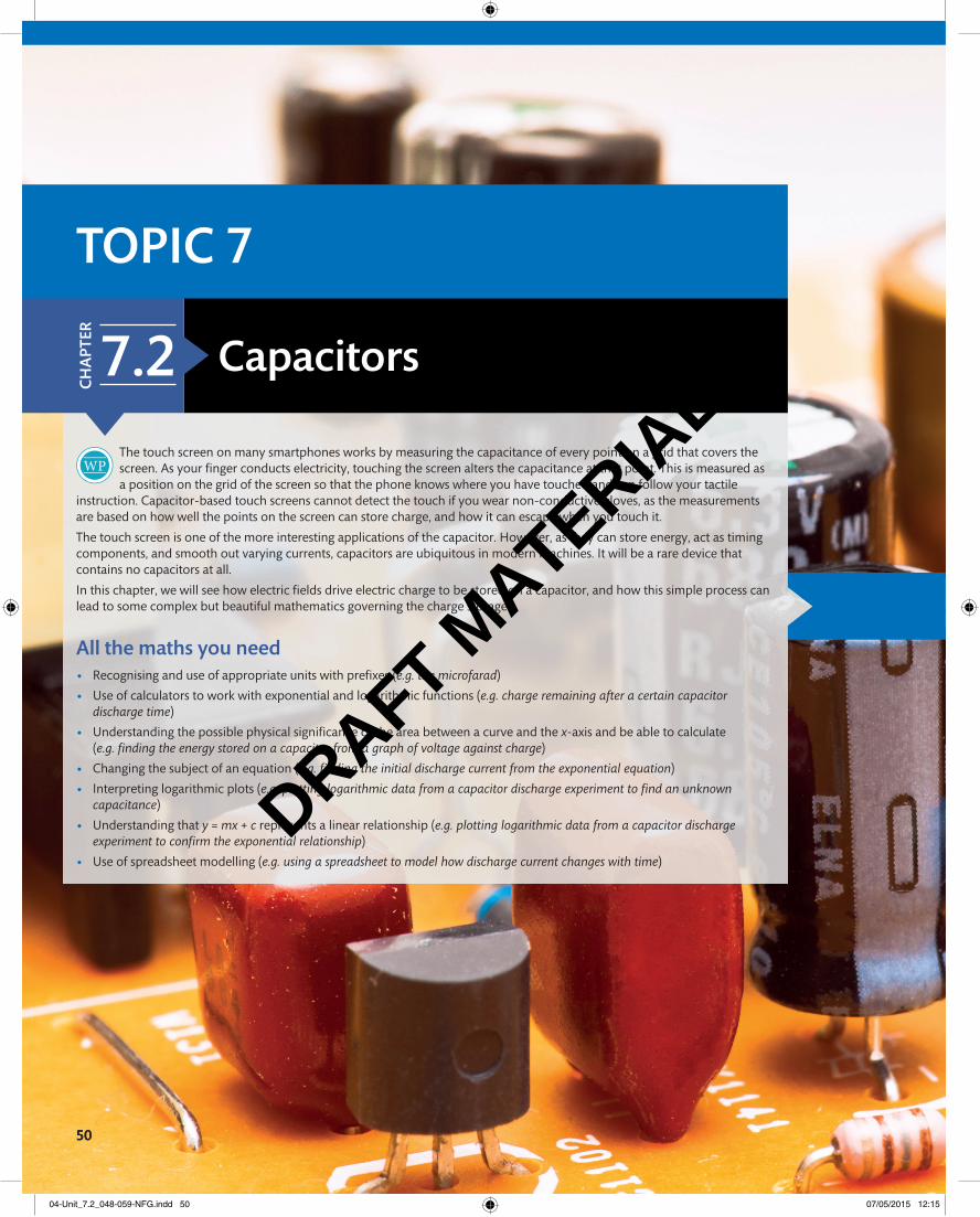
The touch screen on many smartphones works by measuring the capacitance of every point on a grid that covers the screen. As your fi nger conducts electricity, touching the screen alters the capacitance at that point. This is measured as a position on the grid of the screen so that the phone knows where you have touched and can follow your tactile
instruction. Capacitor-based touch screens cannot detect the touch if you wear non-conductive gloves, as the measurements are based on how well the points on the screen can store charge, and how it can escape when you touch it.
The touch screen is one of the more interesting applications of the capacitor. However, as they can store energy, act as timing components, and smooth out varying currents, capacitors are ubiquitous in modern machines. It will be a rare device that contains no capacitors at all.
In this chapter, we will see how electric fi elds drive electric charge to be stored on a capacitor, and how this simple process can lead to some complex but beautiful mathematics governing the charge storage.
All the maths you need • Recognising and use of appropriate units with prefi xes (e.g. the microfarad)
• Use of calculators to work with exponential and logarithmic functions (e.g. charge remaining after a certain capacitor discharge time)
• Understanding the possible physical signifi cance of the area between a curve and the x-axis and be able to calculate (e.g. fi nding the energy stored on a capacitor from a graph of voltage against charge)
• Changing the subject of an equation (e.g. fi nding the initial discharge current from the exponential equation)
• Interpreting logarithmic plots (e.g. plotting logarithmic data from a capacitor discharge experiment to fi nd an unknown capacitance)
• Understanding that y = mx + c represents a linear relationship (e.g. plotting logarithmic data from a capacitor discharge experiment to confi rm the exponential relationship)
• Use of spreadsheet modelling (e.g. using a spreadsheet to model how discharge current changes with time)
ToPIC 7
CH
APT
er
7.2 Capacitors
04-Unit_7.2_048-059-NFG.indd 50 07/05/2015 12:15
DRAFT MATERIA
L
5151
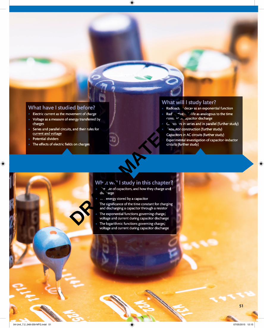
What have I studied before?• Electric current as the movement of charge
• Voltage as a measure of energy transferred by charges
• Series and parallel circuits, and their rules for current and voltage
• Potential dividers
• The effects of electric fi elds on charges
What will I study in this chapter?• The role of capacitors, and how they charge and
discharge
• The energy stored by a capacitor
• The signifi cance of the time constant for charging and discharging a capacitor through a resistor
• The exponential functions governing charge, voltage and current during capacitor discharge
• The logarithmic functions governing charge, voltage and current during capacitor discharge
What will I study later?• Radioactive decay as an exponential function
• Radioactive half-life as analogous to the time constant in capacitor discharge
• Capacitors in series and in parallel (further study)
• Capacitor construction (further study)
• Capacitors in AC circuits (further study)
• Experimental investigation of capacitor-inductor circuits (further study)
04-Unit_7.2_048-059-NFG.indd 51 07/05/2015 12:15
DRAFT MATERIA
L
52
1 7.2
By the end of this section, you should be able to…
● understand how capacitors can be used in a circuit to store charge
● use the equation for capacitance, C = Q
__ V
● use the equations for energy stored on a capacitor
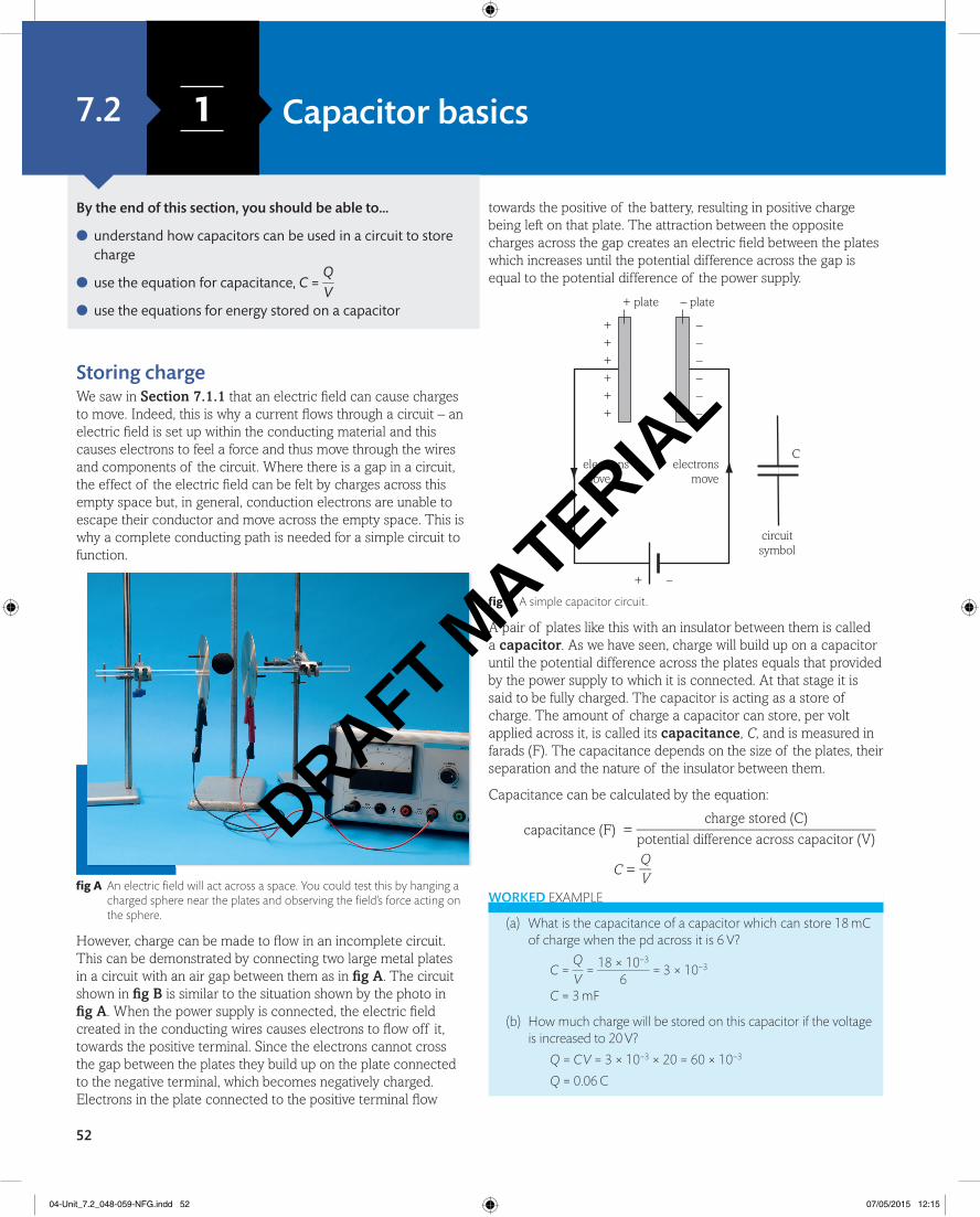
Storing charge We saw in Section 7.1.1 that an electric fi eld can cause charges to move. Indeed, this is why a current fl ows through a circuit – an electric fi eld is set up within the conducting material and this causes electrons to feel a force and thus move through the wires and components of the circuit. Where there is a gap in a circuit, the effect of the electric fi eld can be felt by charges across this empty space but, in general, conduction electrons are unable to escape their conductor and move across the empty space. This is why a complete conducting path is needed for a simple circuit to function.
fi g A an electric fi eld will act across a space. You could test this by hanging a charged sphere near the plates and observing the fi eld’s force acting on the sphere.
However, charge can be made to fl ow in an incomplete circuit. This can be demonstrated by connecting two large metal plates in a circuit with an air gap between them as in fi g A . The circuit shown in fi g B is similar to the situation shown by the photo in fi g A . When the power supply is connected, the electric fi eld created in the conducting wires causes electrons to fl ow off it, towards the positive terminal. Since the electrons cannot cross the gap between the plates they build up on the plate connected to the negative terminal, which becomes negatively charged. Electrons in the plate connected to the positive terminal fl ow
Capacitor basics
towards the positive of the battery, resulting in positive charge being left on that plate. The attraction between the opposite charges across the gap creates an electric fi eld between the plates which increases until the potential difference across the gap is equal to the potential difference of the power supply.
++++++
––––––
+ –
– plate+ plate
electronsmove
Celectrons
move
circuitsymbol
fi g B a simple capacitor circuit.
A pair of plates like this with an insulator between them is called a capacitor. As we have seen, charge will build up on a capacitor until the potential difference across the plates equals that provided by the power supply to which it is connected. At that stage it is said to be fully charged. The capacitor is acting as a store of charge. The amount of charge a capacitor can store, per volt applied across it, is called its capacitance, C, and is measured in farads (F). The capacitance depends on the size of the plates, their separation and the nature of the insulator between them.
Capacitance can be calculated by the equation:
capacitance (F) = charge stored (C)
_________________________________ potential difference across capacitor (V)
C = Q
__ V
WorkeD example
(a) What is the capacitance of a capacitor which can store 18 mC of charge when the pd across it is 6 V?
C = Q
__ V
= 18 × 10−3 __________
6 = 3 × 10⁻³
C = 3 mF
(b) How much charge will be stored on this capacitor if the voltage is increased to 20 V?
Q = C V = 3 × 10−3 × 20 = 60 × 10−3
Q = 0.06 C
04-Unit_7.2_048-059-NFG.indd 52 07/05/2015 12:15
DRAFT MATERIA
L
7 Behaviour can be learned8 8Capacitors 7.2
53
WorkeD example
What is the energy stored on a charged 100 µF capacitor which has 3 mC of charge?
E = 1 __ 2 Q2
___ C
= 1 __ 2 × (3 × 10−3)2
____________ (100 × 10−6)
E = 0.045 J
InvestigationInvestigating energy stored on a capacitor
total resistance = R .fi g E Investigating how energy stored on a capacitor can be altered.
You can investigate how the energy stored on a capacitor changes with the voltage used to charge it. Various combinations of identical series and parallel bulbs will have different overall resistances. If we add an extra parallel branch and increase the number of bulbs on each branch by one, we can keep the total resistance constant, but have more bulbs to light up. The three groups of bulbs in fi g e all have the same resistance, R. By allowing our charged capacitor to discharge through these different groups of bulbs, and altering the voltage to keep the bulb brightness constant, we can confi rm our equation E = 1 __ 2 CV 2 for the energy stored on the capacitor.
Questions
1 What is the capacitance of a capacitor which stores 2 coulombs of charge for every 100 volts applied to it?
2 A 0.01 F capacitor is charged by and then isolated from an 8 V power supply.
(a) Calculate the charge stored.
(b) The capacitor is then connected across another identical capacitor which is uncharged. Describe and explain what will happen to the charge and voltage on each capacitor.
3 How much energy is stored on a 50 µF capacitor which is charged to 12 V?
4 A 1200 µF capacitor is connected to a voltage supply until fully charged with 10.8 mC. If this capacitor is then disconnected and reconnected across a 10 W light bulb, how long could it light the bulb for?
key defi nitions A capacitor is an electrical circuit component that stores charge, and hence can be used as an energy store.
Capacitance is a measure of the capability of a capacitor; the amount of charge stored per unit voltage across the capacitor. It is measured in farads, F.
InvestigationInvestigating stored charge
A device that will measure the amount of charge directly is called a coulombmeter. By charging a capacitor to various different voltages, and discharging through the coulombmeter each time, you can
verify the basic capacitor equation that C = Q
__ V
. A graph of charge (on
the y-axis) against pd (on the x-axis) should produce a straight line through the origin. The gradient of this line will equal the capacitance.
fi g C a coulombmeter will measure how much charge is stored.
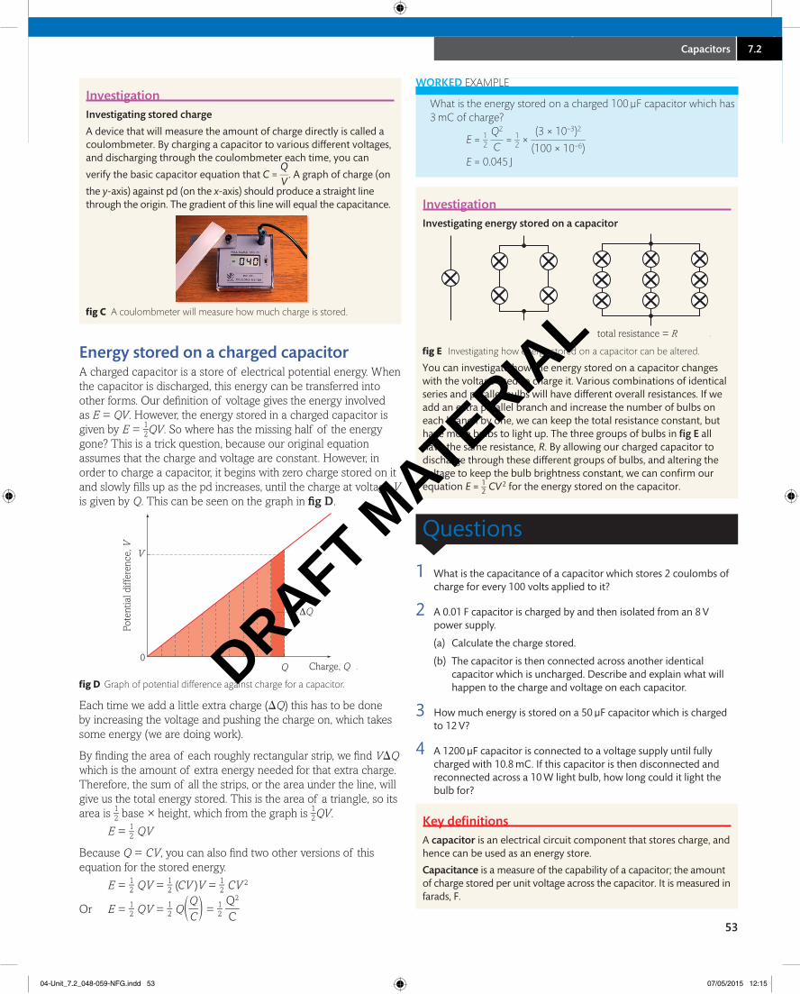
energy stored on a charged capacitorA charged capacitor is a store of electrical potential energy. When the capacitor is discharged, this energy can be transferred into other forms. Our defi nition of voltage gives the energy involved as E = QV. However, the energy stored in a charged capacitor is given by E = 1 _ 2 QV. So where has the missing half of the energy gone? This is a trick question, because our original equation assumes that the charge and voltage are constant. However, in order to charge a capacitor, it begins with zero charge stored on it and slowly fi lls up as the pd increases, until the charge at voltage V is given by Q. This can be seen on the graph in fi g D.
Pote
ntia
l diff
eren
ce, V
Charge, QQ0
ΔQ
V
.fi g D Graph of potential difference against charge for a capacitor.
Each time we add a little extra charge (DQ) this has to be done by increasing the voltage and pushing the charge on, which takes some energy (we are doing work).
By fi nding the area of each roughly rectangular strip, we fi nd VDQ which is the amount of extra energy needed for that extra charge. Therefore, the sum of all the strips, or the area under the line, will give us the total energy stored. This is the area of a triangle, so its area is 1 _ 2 base × height, which from the graph is 1 _ 2 QV.
E = 1 _ 2 QV
Because Q = CV, you can also fi nd two other versions of this equation for the stored energy.
E = 1 _ 2 QV = 1 _ 2 (CV )V = 1 _ 2 CV 2
Or E = 1 _ 2 QV = 1 _ 2 Q ( Q
__ C
) = 1 _ 2 Q2
___ C
04-Unit_7.2_048-059-NFG.indd 53 07/05/2015 12:15
DRAFT MATERIA
L
54
2 Charging and discharging capacitors
Capacitor discharge curves
InvestigationInvestigating current flow through a capacitor
A
6 V 100 Ω
100 µF
currentsensor computer
data-loggingcurrent
B
.fig A Investigating how the current through a capacitor changes over time.
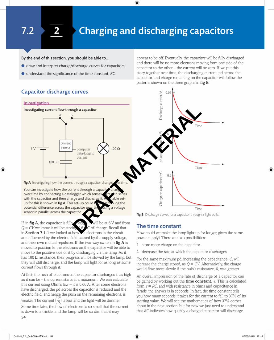
You can investigate how the current through a capacitor changes over time by connecting a datalogger which senses current in series with the capacitor and then charge and discharge it. A suitable set-up for this is shown in fig A. This set-up could be altered to log the potential difference across the capacitor over time, using a voltage sensor in parallel across the capacitor.
If, in fig A, the capacitor is fully charged, it will be at 6 V and from Q = CV we know it will be storing 0.6 mC of charge. Recall that in Section 7.1.1 we looked at how the electrons in the circuit are influenced by the electric field caused by the supply voltage, and their own mutual repulsion. If the two-way switch in fig A is moved to position B, the electrons on the capacitor will be able to move to the positive side of it by discharging via the lamp. As it has 100 Ω resistance, their progress will be slowed by the lamp, but they will still discharge, and the lamp will light for as long as some current flows through it.
At first, the rush of electrons as the capacitor discharges is as high as it can be – the current starts at a maximum. We can calculate this current using Ohm’s law – it is 0.06 A. After some electrons have discharged, the pd across the capacitor is reduced and the electric field, and hence the push on the remaining electrons, is
weaker. The current ( V
__ R
) is less and the light will be dimmer.
Some time later, the flow of electrons is so small that the current is down to a trickle, and the lamp will be so dim that it may
appear to be off. Eventually, the capacitor will be fully discharged and there will be no more electrons moving from one side of the capacitor to the other – the current will be zero. If we put this story together over time, the discharging current, pd across the capacitor, and charge remaining on the capacitor will follow the patterns shown on the three graphs in fig B.
Time
Dis
char
ge c
urre
nt/A 0.06
Time
pd a
cros
s ca
paci
tor/
V
6.0
Time
Cha
rge
on c
apac
itor/
mC
0.6
fig B Discharge curves for a capacitor through a light bulb.
The time constantHow could we make the lamp light up for longer, given the same power supply? There are two possibilities:
1 store more charge on the capacitor
2 decrease the rate at which the capacitor discharges.
For the same maximum pd, increasing the capacitance, C, will increase the charge stored, as Q = CV. Alternatively, the charge would flow more slowly if the bulb’s resistance, R, was greater.
An overall impression of the rate of discharge of a capacitor can be gained by working out the time constant, t. This is calculated from t = RC, and with resistance in ohms and capacitance in farads, the answer is in seconds. In fact, the time constant tells you how many seconds it takes for the current to fall to 37% of its starting value. We will see the mathematics of how 37% comes about in the next section, but for now we just need to understand that RC indicates how quickly a charged capacitor will discharge.
By the end of this section, you should be able to…
● draw and interpret charge/discharge curves for capacitors
● understand the significance of the time constant, RC
7.2
04-Unit_7.2_048-059-NFG.indd 54 07/05/2015 12:15
DRAFT MATERIA
L
7 Behaviour can be learned8 8Capacitors 7.2
55
WorkeD example
What is the time constant for the capacitor in the circuit shown in fi g A?
t = RC = 100 × 100 × 10−6
t = 0.01 s
Thus, in reality, the light bulb shown in fi g A might fl ash on and off so quickly that we could not spot it!
Car courtesy lightsModern cars often have a light in the cabin which comes on when the door is opened, and remains on for a short time after the door is closed. This is useful in case it is dark, allowing the driver to see to put the key in the ignition. The light functions by having a capacitor discharge through the light bulb so that it dims and goes off as the charge runs out. In some cars, the length of time for which the light remains on after the door is closed is adjustable and can be set by the vehicle owner. This adjustable setting makes use of the idea of the time constant, RC. The owner will be able to adjust a switch connected to the courtesy light circuit which connects more or less resistance to the discharging circuit. Thus for the same fully charged capacitor, the time taken to discharge completely will vary and the courtesy light illuminates the cabin for more or less time.
fi g C Capacitor discharge is used in a car courtesy light.
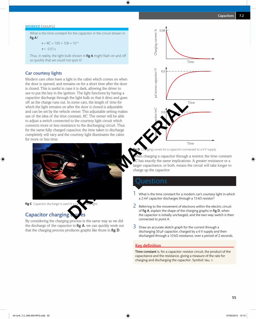
Capacitor charging curvesBy considering the charging process in the same way as we did the discharge of the capacitor in fi g A, we can quickly work out that the charging process produces graphs like those in fi g D.
Time
Cha
rgin
g cu
rren
t/A 0.06
Time
pd a
cros
s ca
paci
tor/
V
6.0
Time
Cha
rge
on c
apac
itor/
mC
0.6
fi g D Charging curves for a capacitor connected to a 6 V supply.
When charging a capacitor through a resistor, the time constant RC has exactly the same implications. A greater resistance or a larger capacitance, or both, means the circuit will take longer to charge up the capacitor.
Questions
1 What is the time constant for a modern car’s courtesy light in which a 2 mF capacitor discharges through a 15 kΩ resistor?
2 Referring to the movement of electrons within the electric circuit of fi g A, explain the shape of the charging graphs in fi g D, when the capacitor is initially uncharged, and the two-way switch is then connected to point A.
3 Draw an accurate sketch graph for the current through a discharging 50 µF capacitor, charged by a 6 V supply and then discharged through a 10 kΩ resistance, over a period of 2 seconds.
key defi nition Time constant is, for a capacitor-resistor circuit, the product of the capacitance and the resistance, giving a measure of the rate for charging and discharging the capacitor. Symbol: tau, t.
04-Unit_7.2_048-059-NFG.indd 55 07/05/2015 12:15
DRAFT MATERIA
L
56
3 Capacitor mathematics
Discharging capacitor mathsCharge, QWe have seen that the charging and discharging of a capacitor follows curving graphs in which the current is constantly changing, and so the rate of change of charge and pd are also constantly changing. These graphs are known as exponential curves. The shapes can be produced by plotting mathematical formulae which have power functions in them. In the case of discharging a capacitor, C, through a resistor, R, the function which describes the charge remaining on the capacitor, Q, at a time, t, is
Q = Q0e−t/RC
where Q0 is the initial charge on the capacitor, and e is the special mathematical number which is used in the inverse function of natural logarithms (e ≈ 2.718).
WorkeD example
a 0.03 F capacitor is fully charged by a 12 V supply and is then connected to discharge through a 900 Ω resistor. How much charge remains on the capacitor after 20 seconds?
Initial charge, Q0 = CV = 0.03 × 12 = 0.36 C
Q = Q0e−t/RC
Q = 0.36 × e(−20/900 × 0.03) = 0.36 × e(−20/27) = 0.36 × 0.477
Q = 0.17 C
Voltage, VThe pd across a discharging capacitor will fall as the charge stored falls. By substituting the equation Q = CV into our exponential decay equation we can show the formula that describes voltage on a discharging capacitor is in exactly the same form as for the charge itself:
Q = Q0e−t/RC and Q = CV
(which also means that initially, Q0 = CV0)
CV = CV0e−t/RC
from which the capacitance term, C, can be cancelled, leaving:
V = V0e−t/RC
WorkeD example
a 0.03 F capacitor is fully charged by a 12 V supply and is then connected to discharge through a 900 Ω resistor. What is the pd on the capacitor after 20 seconds?
Initial voltage is the same as the supply at 12 V
V = V0e−t/RC
V = 12 × e(−20/900 × 0.03) = 12 × e(−20/27) = 12 × 0.477
V = 5.7 V
Current, IAs we saw in Section 7.2.2, the discharging current also dies away following an exponential curve. Ohm’s law tells us that V = IR, and hence V0 = I0R.
V = V0e−t/RC
IR = I0Re−t/RC
from which the resistance term, R, will cancel on both sides:I = I0e−t/RC
WorkeD example
a 0.03 F capacitor is fully charged by a 12 V supply and is then connected to discharge through a 900 Ω resistor. What is the discharge current after 20 seconds?
Initial voltage is the same as the supply at 12 V, so the initial current is
I0 = V0/R = 12/900 = 0.013 a
I = I0e−t/RC
I = 0.013 × e(−2/900 × 0.03) = 0.013 × e(−20/27) = 0.013 × 0.477
I = 6.4 ma
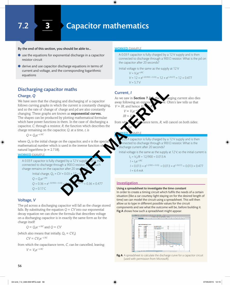
InvestigationUsing a spreadsheet to investigate the time constantIn order to create a timing circuit which fulfils the needs of a certain situation (like a car courtesy light staying on for the desired length of time) we can model the circuit using a spreadsheet. This will then allow us to type in different possible values for the circuit components and see what the outcome will be, before building it. Fig A shows how such a spreadsheet might appear.
fig A a spreadsheet to calculate the discharge curve for a capacitor circuit (used with permission from microsoft).
By the end of this section, you should be able to…
● use the equations for exponential discharge in a capacitor resistor circuit
● derive and use capacitor discharge equations in terms of current and voltage, and the corresponding logarithmic equations
7.2
04-Unit_7.2_048-059-NFG.indd 56 07/05/2015 12:15
DRAFT MATERIA
L
7 Behaviour can be learned8 8Capacitors 7.2
57
You can create the spreadsheet without doing any experimentation. Give the various cells formulae to calculate what capacitor theory tells us will happen, using the mathematics on these pages. For example, the cell giving the time constant, t, does not require input from the user – it is programmed to display the multiplication of the capacitance and the discharge resistance. This value is then used in the formula for calculating the values in the current column, using the equation, I = I0e−t/RC, or I = I0e−t/t.
Capacitor calculusThe equation for charge on a discharging capacitor is the solution to a differential equation based on considering the rules for voltages around the discharging circuit. With only the capacitor, C, and resistance, R, in the circuit, the emf is zero. So,
0 = VC + VR
Vc = Q/C and VR = IR
[ −IR = Q/C
The current is the rate of change of charge,
I = dQ
___ dt
So − R dQ
_____ dt
= Q
__ C
dQ
___ Q
= −dt
____ RC
Integrating this from the start to time t, i.e. from capacitor charge, Q0 to Q:
∫ Q0
Q
dQ
___ Q
∫ 0 t
−dt
____ RC
gives ln Q – ln Q0 = −t
___ RC
or ln Q = ln Q0 − t ___
RC
applying the inverse function of natural logarithm gives:
Q = Q0e−t/RC
Logarithmic equations for voltageWe can take the log equation for charge and make substitutions to find equivalent equations for voltage and for current.
ln Q = ln Q0 − t ___
RC
[ ln (CV) = ln (CV0) − t ___
RC
[ ln C + ln V = ln C + ln V0 − t ___
RC
C is fixed, so ln C is the same on both sides.
[ ln V = ln V0 − t ___
RC
applying the inverse function of natural logarithm gives:
V = V0e−t/RC
Logarithmic equations for current Similarly, we can take the log equation for charge and make substitutions to find equivalent equations for current.
ln V = ln V0 − t ___
RC
[ ln (IR) = ln (I0R) − t ___
RC
[ ln I + ln R = ln I0 + ln R − t ___
RC
R is fixed, so ln R is the same on both sides.
[ ln I = ln I0 − t ___
RC
applying the inverse function of natural logarithm gives:
I = I0e−t/RC
The ‘37% life’If we consider the charge at time t,
t = t = RC so − t ___
RC = −
RC ___
RC = −1
[ Q = Q0e−RC/RC
Q = Q0e−1 and e−1 = 0.37
So Q = 0.37Q0
the charge is 37% of its original value.
This shows that the time constant describes the decay of charge on a discharging capacitor in just the same way as radioactive half-life describes the number of radioactive nuclei remaining (see Section 10.1.2) except that instead of describing the time taken to reach half of the initial value, t is the time taken to reach 37% of the initial value. This similarity comes from the fact that radioactive decay also follows an exponential equation: N = N0e−t.
Questions
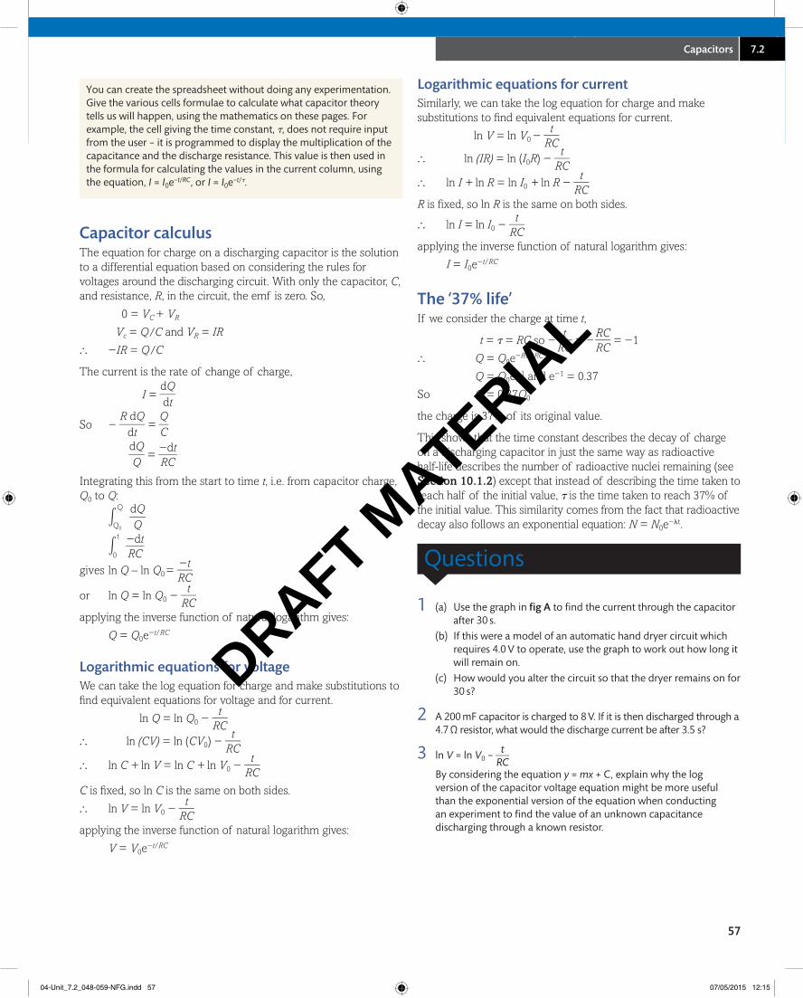
1 (a) Use the graph in fig A to find the current through the capacitor after 30 s.
(b) If this were a model of an automatic hand dryer circuit which requires 4.0 V to operate, use the graph to work out how long it will remain on.
(c) How would you alter the circuit so that the dryer remains on for 30 s?
2 A 200 mF capacitor is charged to 8 V. If it is then discharged through a 4.7 Ω resistor, what would the discharge current be after 3.5 s?
3 ln V = ln V0 − t ____ RC
By considering the equation y = mx + C, explain why the log version of the capacitor voltage equation might be more useful than the exponential version of the equation when conducting an experiment to find the value of an unknown capacitance discharging through a known resistor.
04-Unit_7.2_048-059-NFG.indd 57 07/05/2015 12:15
DRAFT MATERIA
L
THINKING
Where else will I encounter these themes?
58
Book 1 6.1 6.2 7.1 7.2 7.3 8.1 8.27.3YOU ARE HERE
ULTrACAPACITorSElectric vehicles have not yet made a large impact in society, and their most commonly perceived failings are a lack of overall energy storage, limiting range between charges, and long charging times. Ultracapacitors have been suggested as a possible solution to these problems, as a replacement for electrochemical rechargeable batteries.
PAPER-BASED ULTRACAPACITORS WITH CARBON NANOTUBES–GRAPHENE COMPOSITES
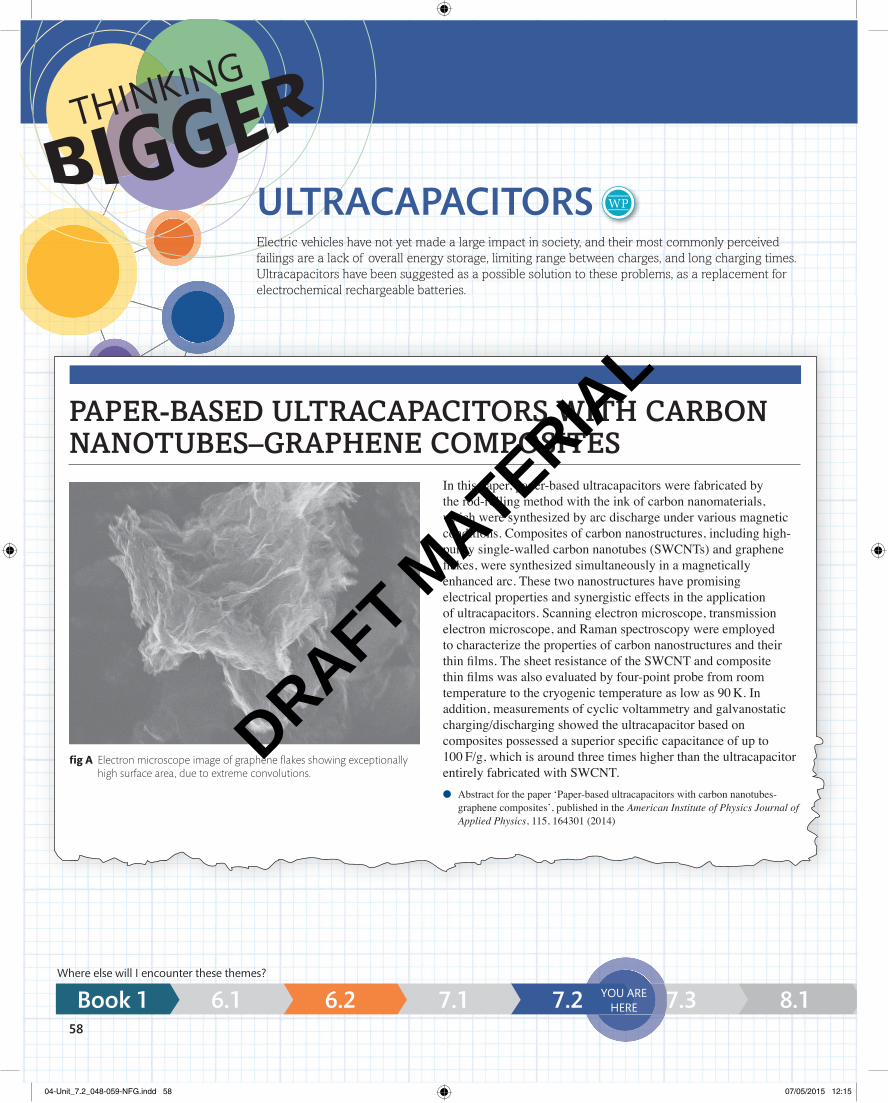
fi g A electron microscope image of graphene fl akes showing exceptionally high surface area, due to extreme convolutions.
In this paper, paper-based ultracapacitors were fabricated by the rod-rolling method with the ink of carbon nanomaterials, which were synthesized by arc discharge under various magnetic conditions. Composites of carbon nanostructures, including high-purity single-walled carbon nanotubes (SWCNTs) and graphene fl akes, were synthesized simultaneously in a magnetically enhanced arc. These two nanostructures have promising electrical properties and synergistic effects in the application of ultracapacitors. Scanning electron microscope, transmission electron microscope, and Raman spectroscopy were employed to characterize the properties of carbon nanostructures and their thin fi lms. The sheet resistance of the SWCNT and composite thin fi lms was also evaluated by four-point probe from room temperature to the cryogenic temperature as low as 90 K. In addition, measurements of cyclic voltammetry and galvanostatic charging/discharging showed the ultracapacitor based on composites possessed a superior specifi c capacitance of up to 100 F/g, which is around three times higher than the ultracapacitor entirely fabricated with SWCNT.
● Abstract for the paper ‘Paper-based ultracapacitors with carbon nanotubes-graphene composites’, published in the American Institute of Physics Journal of Applied Physics, 115, 164301 (2014)
04-Unit_7.2_048-059-NFG.indd 58 07/05/2015 12:15
DRAFT MATERIA
L
7 Behaviour can be learned8 8Thinking Bigger 1 7.2
59
8.2 8.3 9.1 10.1 11.1 12.1 13.1
Let us start by considering the nature of the writing in this journal abstract.
If you search online for ‘graphene ultracapacitors’ there are several articles in more everyday language which explain the essence of this scienti� c paper, for comparison.
1. The extract opposite consists of information from a peer-reviewed scientifi c paper.
a. Discuss the tone and level of vocabulary included in the article – who is the intended audience?
b. Discuss the level of scientifi c detail included in the extract, particularly considering the intended audience.
ActivityDraw a fl owchart detailing the steps that the authors say their paper will explain to a reader. Your fl owchart can use technical terms, but should be written in layman’s terms as much as is possible.
Did you know? Isolated capacitors can hold their charge for years without losing much at all. It is important that any unfamiliar large capacitor is assumed to be fully charged, as it could give a shock if it discharges through you.
Now we will look at the physics in detail. Some of these questions will link to topics elsewhere in this book, so you may need to combine concepts from different areas of physics to work out the answers.
2. a. Explain the meaning of the phrase ‘specifi c capacitance’ bearing in mind that it was quoted as being 100 F g−1.
b. How does the specifi c capacitance affect the potential use of a capacitor as an energy store in an electric car?
3. Explain the importance of the resistance of a capacitor.
4. The fundamental point of a capacitor is to store charge. Graphene fl akes have an exceptionally high surface area (see fi g A). Explain why the incorporation of graphene fl akes into capacitor construction could make very high capacitances possible.
Consider how we calculate the time constant, τ, as well as the idea of internal resistance.
Your � owchart should be in the chronological order that the scientists would have had to work on building and testing the materials and then building their ultracapacitors.
04-Unit_7.2_048-059-NFG.indd 59 07/05/2015 12:16
DRAFT MATERIA
L
60
4 The diagram shows a circuit that includes a capacitor:
(a) (i) Explain what happens to the capacitor when the switch is closed. [2]
(ii) The potential difference (pd) across the resistor rises to a maximum as the switch is closed.
Explain why this pd subsequently decreases to zero. [2]
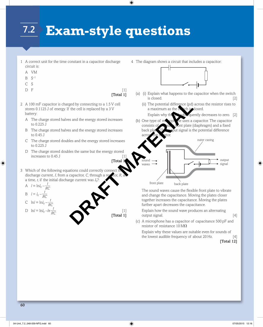
(b) One type of microphone uses a capacitor. The capacitor consists of a fl exible front plate (diaphragm) and a fi xed back plate. The output signal is the potential difference across the resistor.
outputsignal
outer casing
back platefront plate
soundwaves
The sound waves cause the fl exible front plate to vibrate and change the capacitance. Moving the plates closer together increases the capacitance. Moving the plates further apart decreases the capacitance.
Explain how the sound wave produces an alternating output signal. [4]
(c) A microphone has a capacitor of capacitance 500 pF and resistor of resistance 10 MV
Explain why these values are suitable even for sounds of the lowest audible frequency of about 20 Hz. [4]
[Total 12]
1 A correct unit for the time constant in a capacitor discharge circuit is:
A VM
B S –1
C S
D F [1] [Total 1]
2 A 100 mF capacitor is charged by connecting to a 1.5 V cell stores 0.1125 J of energy. If the cell is replaced by a 3 V battery:
A The charge stored halves and the energy stored increases to 0.225 J
B The charge stored halves and the energy stored increases to 0.45 J
C The charge stored doubles and the energy stored increases to 0.225 J
D The charge stored doubles the same but the energy stored increases to 0.45 J [1]
[Total 1]
3 Which of the following equations could correctly connect the discharge current, I , from a capacitor, C , through a resistor, R , at a time, t, if the initial discharge current was I 0?:
A l = ln l 0 – t ___
RC
B l = l 0 – t ___
RC
C ln l = ln l 0 – t ___
RC
D ln l = ln l 0 –ln t ___
RC [1]
[Total 1]
Exam-style questions 7.2
04-Unit_7.2_048-059-NFG.indd 60 07/05/2015 12:16
DRAFT MATERIA
L
7 Behaviour can be learnedexam-style questions 7.2
61
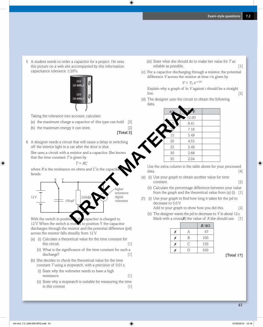
5 A student needs to order a capacitor for a project. He sees this picture on a web site accompanied by this information: capacitance tolerance 620%.
16V 010 000μF
16V 010 000μF
Taking the tolerance into account, calculate:
(a) the maximum charge a capacitor of this type can hold [3]
(b) the maximum energy it can store. [2] [Total 5]
6 A designer needs a circuit that will cause a delay in switching off the interior light in a car after the door is shut.
She uses a circuit with a resistor and a capacitor. She knows that the time constant T is given by
T = RC
where R is the resistance on ohms and C is the capacitance in farads.
higher resistancedigital voltmeter
12 V
X Y
100 μF220 kΩ V
With the switch in position X the capacitor is charged to 12 V. When the switch is moved to position Y the capacitor discharges through the resistor and the potential difference (pd) across the resistor falls steadily from 12 V.
(a) (i) Calculate a theoretical value for the time constant for this circuit. [1]
(ii) What is the signifi cance of the time constant for such a discharge? [1]
(b) She decides to check the theoretical value for the time constant T using a stopwatch, with a precision of 0.01 s.
(i) State why the voltmeter needs to have a high resistance. [1]
(ii) State why a stopwatch is suitable for measuring the time in this context [1]
(iii) State what she should do to make her value for T as reliable as possible. [1]
(c) For a capacitor discharging through a resistor, the potential difference V across the resistor at time t is given by
V = V 0 e –t/RC
Explain why a graph of ln V against t should be a straight line. [2]
(d) The designer uses the circuit to obtain the following data.
t/s V/V
0 12.00
5 9.41
10 7.16
15 5.49
20 4.55
25 3.49
30 2.68
35 2.04
Use the extra column in the table above for your processed data. [4]
(e) (i) Use your graph to obtain another value for time constant. [2]
(ii) Calculate the percentage difference between your value from the graph and the theoretical value from (a) (i). [1]
(f ) (i) Use your graph to fi nd how long it takes for the pd to decrease to 5.0 V.Add to your graph to show how you did this. [2]
(ii) The designer wants the pd to decrease to V in about 12 s. Mark with a cross(✗) the value of R she should use. [1]
R/kV
✗ A 47
✗ B 100
✗ C 150
✗ D 330 [Total 17]
04-Unit_7.2_048-059-NFG.indd 61 07/05/2015 12:16
DRAFT MATERIA
L