Embed Size (px)
Citation preview
DNV GL © 2015 05 May 2017 SAFER, SMARTER, GREENERDNV GL © 2015
05 May 2017Leif Collberg
OIL & GAS
Integrity Management of Offshore Assets
1
Opening session
DNV GL © 2015 05 May 2017
QCWeldingMaterial spec.
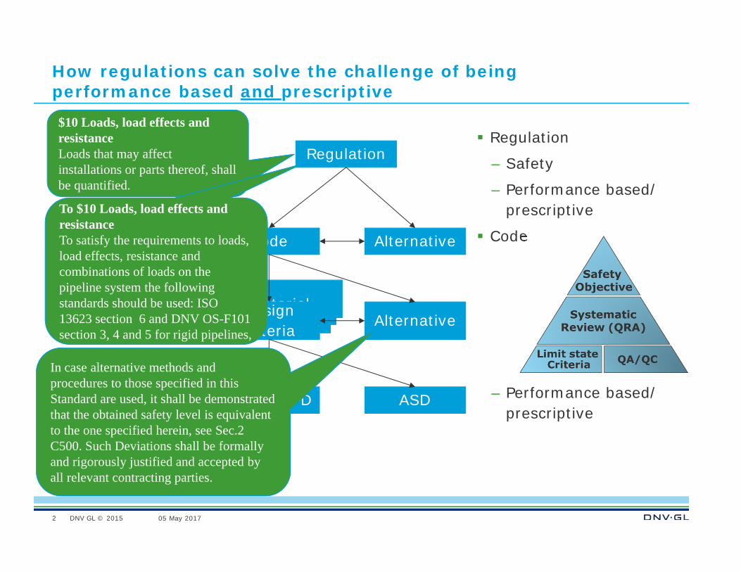
How regulations can solve the challenge of being performance based and prescriptive
Regulation
– Safety
– Performance based/ prescriptive
Code
– Performance based/ prescriptive
2
Regulation
Code Alternative
Design criteria
Alternative
LSBD/LRFD ASD
$10 Loads, load effects and resistance Loads that may affect installations or parts thereof, shall be quantified.
section 3, 4 and 5 for rigid pipelines, …
To $10 Loads, load effects and resistanceTo satisfy the requirements to loads, load effects, resistance and combinations of loads on the pipeline system the following standards should be used: ISO 13623 section 6 and DNV OS-F101 section 3, 4 and 5 for rigid pipelines, …
In case alternative methods and procedures to those specified in this Standard are used, it shall be demonstrated that the obtained safety level is equivalent to the one specified herein, see Sec.2 C500. Such Deviations shall be formally and rigorously justified and accepted by all relevant contracting parties.
DNV GL © 2015 05 May 2017
The Nominal Probability of Failure Where did it come from?
How stringent should the requirements be?
One of the first formal design guidelines was probably given in the ASME standard B.31 (1925).
This was based on some fundamental elements that still apply:
– It requested the pipeline to be pressure tested. It expressed this pressure as a fraction of the Barlow hoop stress times the yield stress. This fraction was 0.9.
– It required that the design pressure should be a fraction of the test pressure; 0.8. And the factor of 0.72 was born.
– It required a lower fraction where the consequences were more severe. I.e. it had some inherent risk principles.

DNV GL © 2015 05 May 2017
The Nominal Probability of Failure Where did it come from?
The classical 0.72 design factor has shown to give an acceptable track record
How can we determine design factors that will give similar track record as the classical 0.72 design factor for new failure modes and construction methods?
– One could calculate the implicit failure probability of these criteria
This was the basis for the work performed within the SUPERB project, a JIP in the first half of the 1990’ies.
DNV GL © 2015 05 May 2017
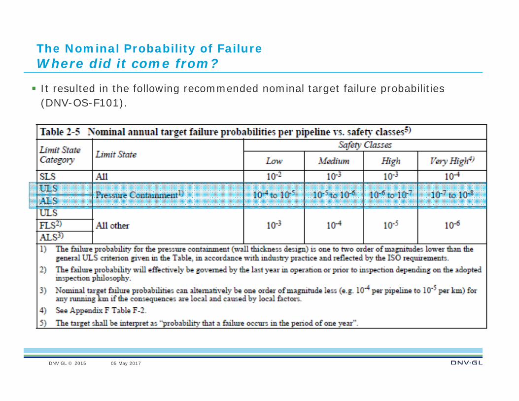
The Nominal Probability of Failure Where did it come from?
It resulted in the following recommended nominal target failure probabilities(DNV-OS-F101).
DNV GL © 2015 05 May 2017
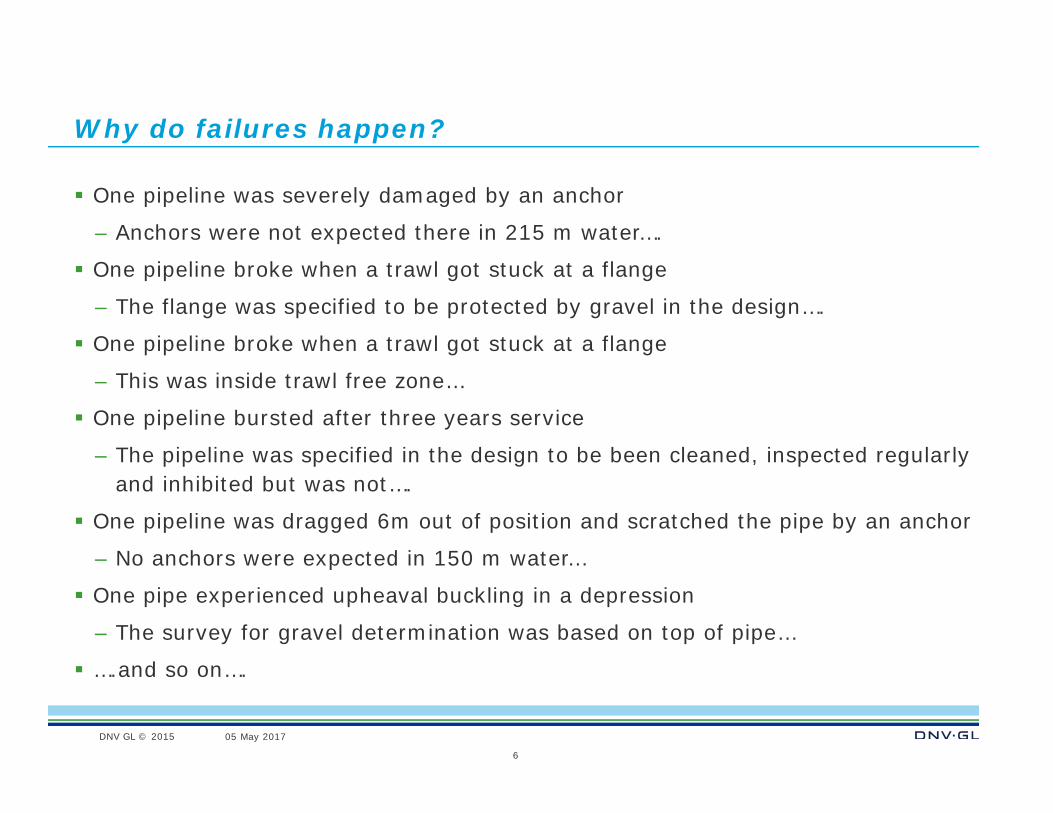
Why do failures happen?
One pipeline was severely damaged by an anchor
– Anchors were not expected there in 215 m water….
One pipeline broke when a trawl got stuck at a flange
– The flange was specified to be protected by gravel in the design….
One pipeline broke when a trawl got stuck at a flange
– This was inside trawl free zone…
One pipeline bursted after three years service
– The pipeline was specified in the design to be been cleaned, inspected regularly and inhibited but was not….
One pipeline was dragged 6m out of position and scratched the pipe by an anchor
– No anchors were expected in 150 m water…
One pipe experienced upheaval buckling in a depression
– The survey for gravel determination was based on top of pipe…
….and so on….
6
DNV GL © 2015 05 May 2017
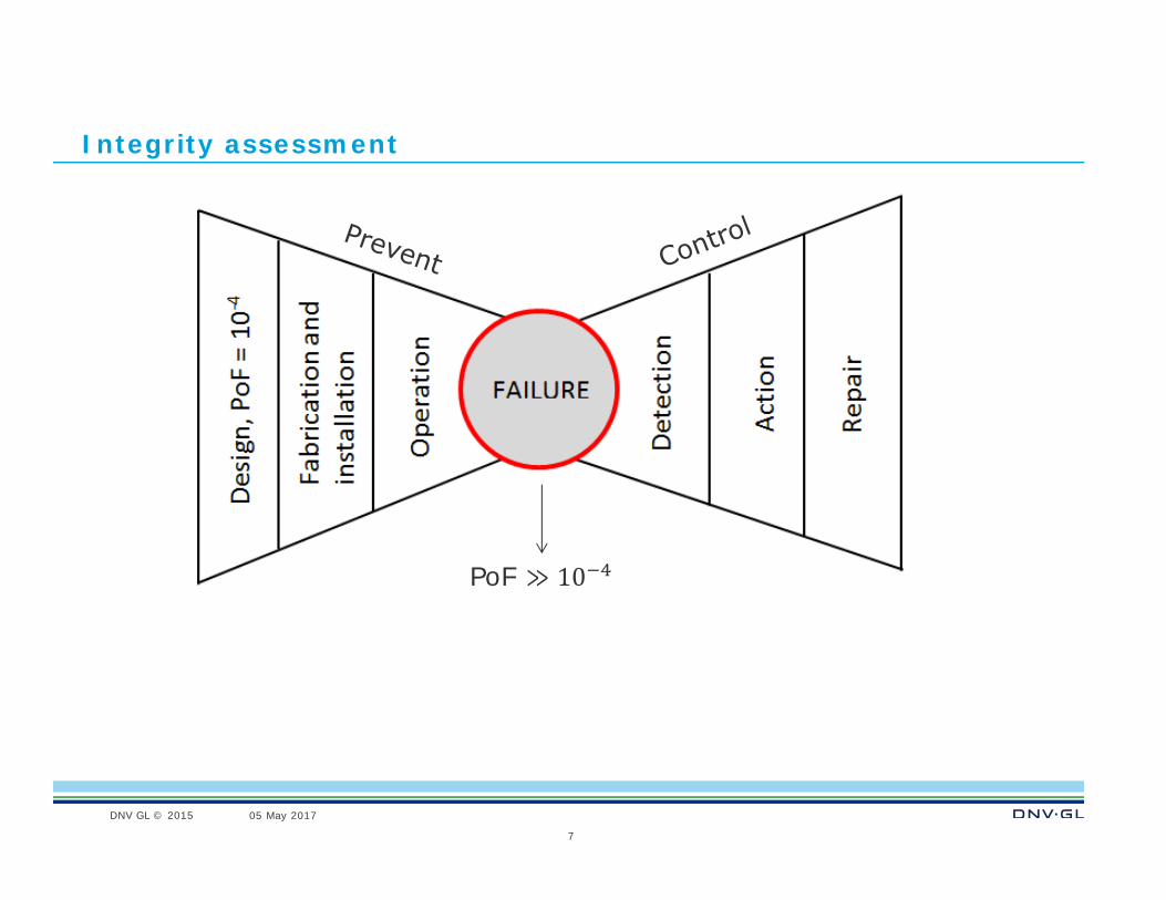
Integrity assessment
7
PoF ≫ 10
DNV GL © 2015 05 May 2017
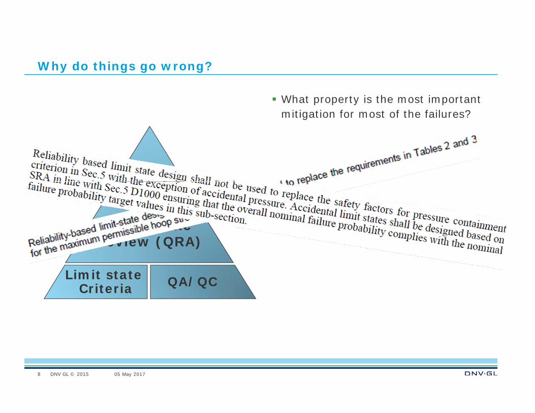
Why do things go wrong?
What property is the most important mitigation for most of the failures?
8
SystematicReview (QRA)
Safety Objective
Limit state Criteria QA/QC
DNV GL © 2015 05 May 2017
Regulations
These should preferably be performance and prescriptive
Performance based are good but needs some knobs/piles
9
DNV GL © 2015 05 May 2017
What is a standard or standardisation?
“on the shelf” design
– Same dimensions
– Same material
The same standard
– The same bases for development of pipelines
10
DNV GL © 2015 05 May 2017
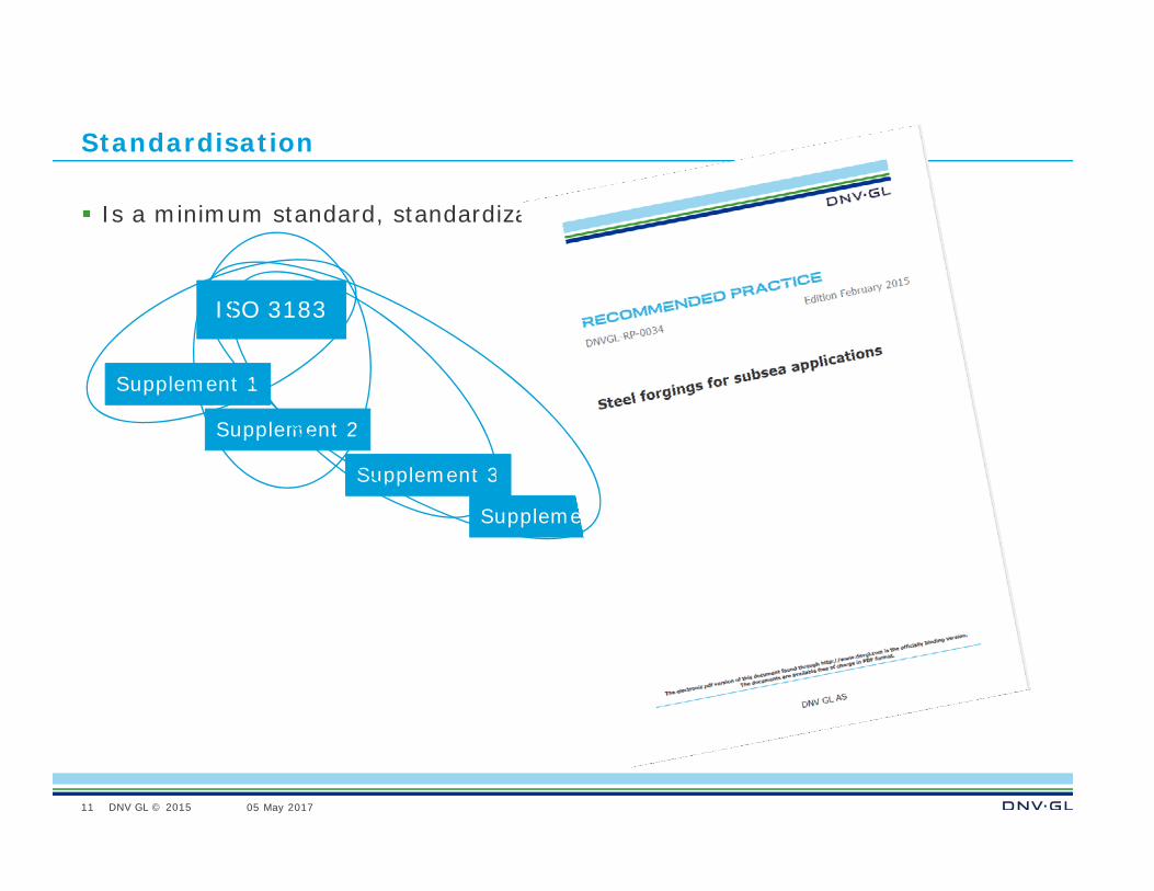
Standardisation
Is a minimum standard, standardization?
11
ISO 3183
Supplement 1
Supplement 2
Supplement 3
Supplement 4
DNV GL © 2015 05 May 2017 SAFER, SMARTER, GREENERDNV GL © 2015
05 May 2017Leif Collberg
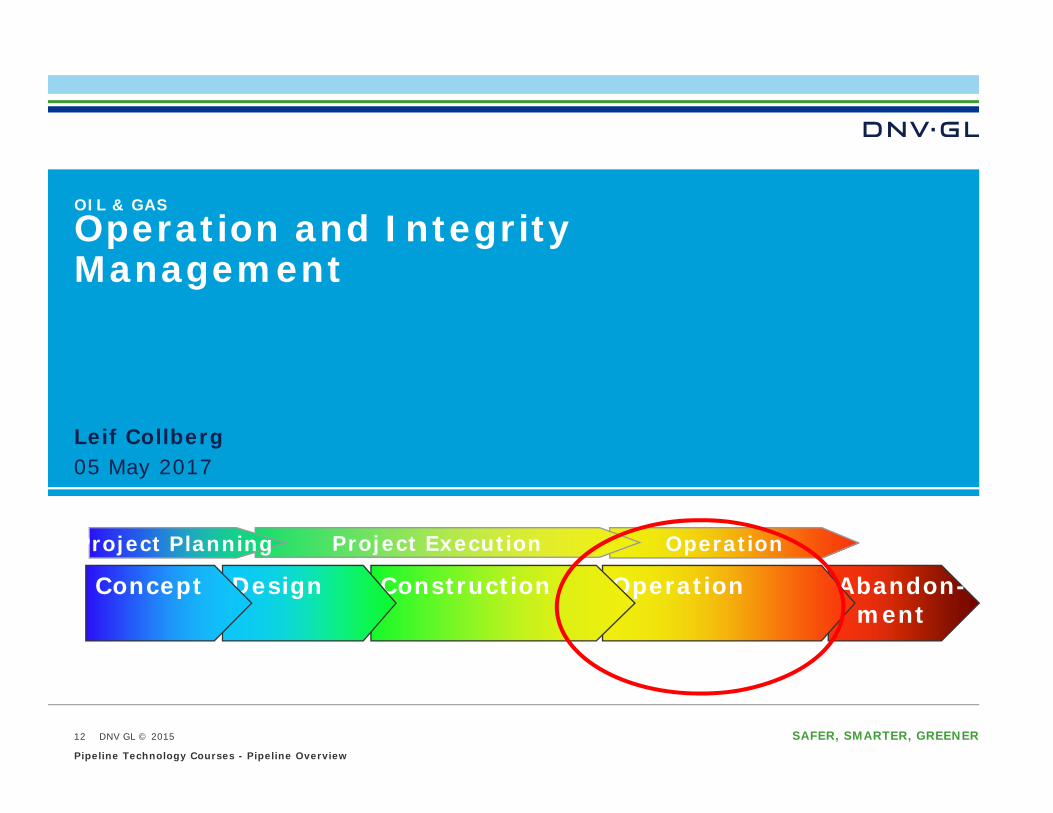
OIL & GAS
Operation and Integrity Management
Abandon-ment
OperationConstructionDesignConcept
OperationProject ExecutionProject Planning
25.05.2017Pipeline Technology Courses - Pipeline Overview
12
DNV GL © 2015 05 May 2017
Pipeline Integrity...
The function of submarine pipeline systems is to efficiently and safely transport a variety of fluids
… the submarine pipeline system’s ability to operate safely and withstand the loads imposed during the pipeline lifecycle. If a system loses this ability, a failure has occurred.
25.05.2017Pipeline Technology Courses - Pipeline Overview
13
DNV GL © 2015 05 May 2017
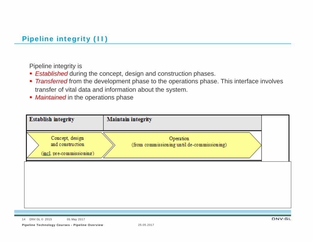
Pipeline integrity (II)
Pipeline integrity is Established during the concept, design and construction phases. Transferred from the development phase to the operations phase. This interface involves
transfer of vital data and information about the system. Maintained in the operations phase
25.05.2017Pipeline Technology Courses - Pipeline Overview
14
DNV GL © 2015 05 May 2017
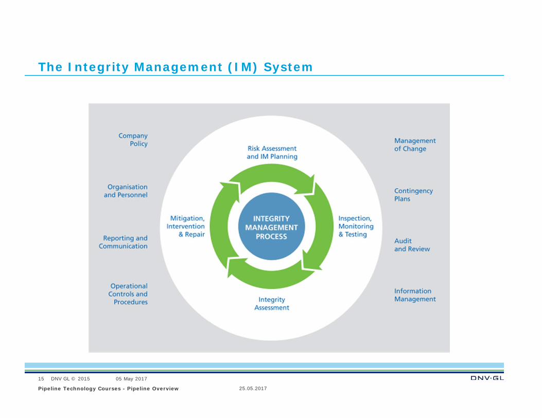
The Integrity Management (IM) System
25.05.2017Pipeline Technology Courses - Pipeline Overview
15
DNV GL © 2015 05 May 2017
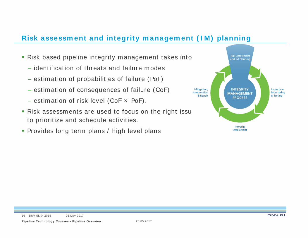
Risk assessment and integrity management (IM) planning
Risk based pipeline integrity management takes into account
– identification of threats and failure modes
– estimation of probabilities of failure (PoF)
– estimation of consequences of failure (CoF)
– estimation of risk level (CoF × PoF).
Risk assessments are used to focus on the right issues at the right time. It is used to prioritize and schedule activities.
Provides long term plans / high level plans
25.05.2017Pipeline Technology Courses - Pipeline Overview
16
DNV GL © 2015 05 May 2017
Improving
Good planning and quality control is very important when improving integrity
25.05.2017Pipeline Technology Courses - Pipeline Overview
17
DNV GL © 2015 05 May 2017
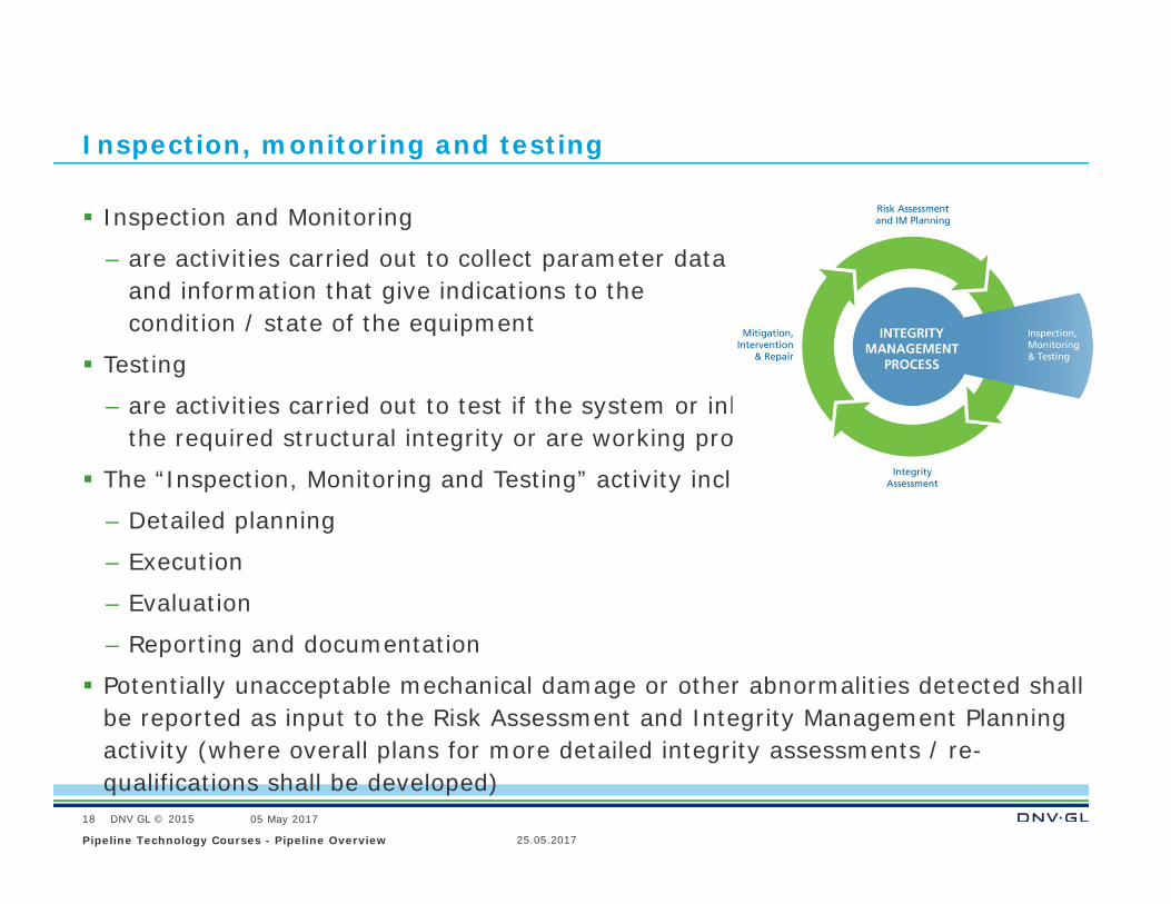
Inspection, monitoring and testing
Inspection and Monitoring
– are activities carried out to collect parameter data and information that give indications to the condition / state of the equipment
Testing
– are activities carried out to test if the system or inherent safety systems have the required structural integrity or are working properly
The “Inspection, Monitoring and Testing” activity includes:
– Detailed planning
– Execution
– Evaluation
– Reporting and documentation
Potentially unacceptable mechanical damage or other abnormalities detected shall be reported as input to the Risk Assessment and Integrity Management Planning activity (where overall plans for more detailed integrity assessments / re-qualifications shall be developed)
25.05.2017Pipeline Technology Courses - Pipeline Overview
18
DNV GL © 2015 05 May 2017
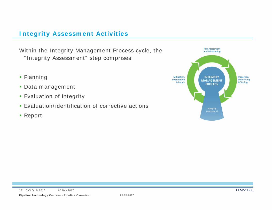
Integrity Assessment Activities
Within the Integrity Management Process cycle, the “Integrity Assessment” step comprises:
Planning
Data management
Evaluation of integrity
Evaluation/identification of corrective actions
Report
25.05.2017Pipeline Technology Courses - Pipeline Overview
19
DNV GL © 2015 05 May 2017
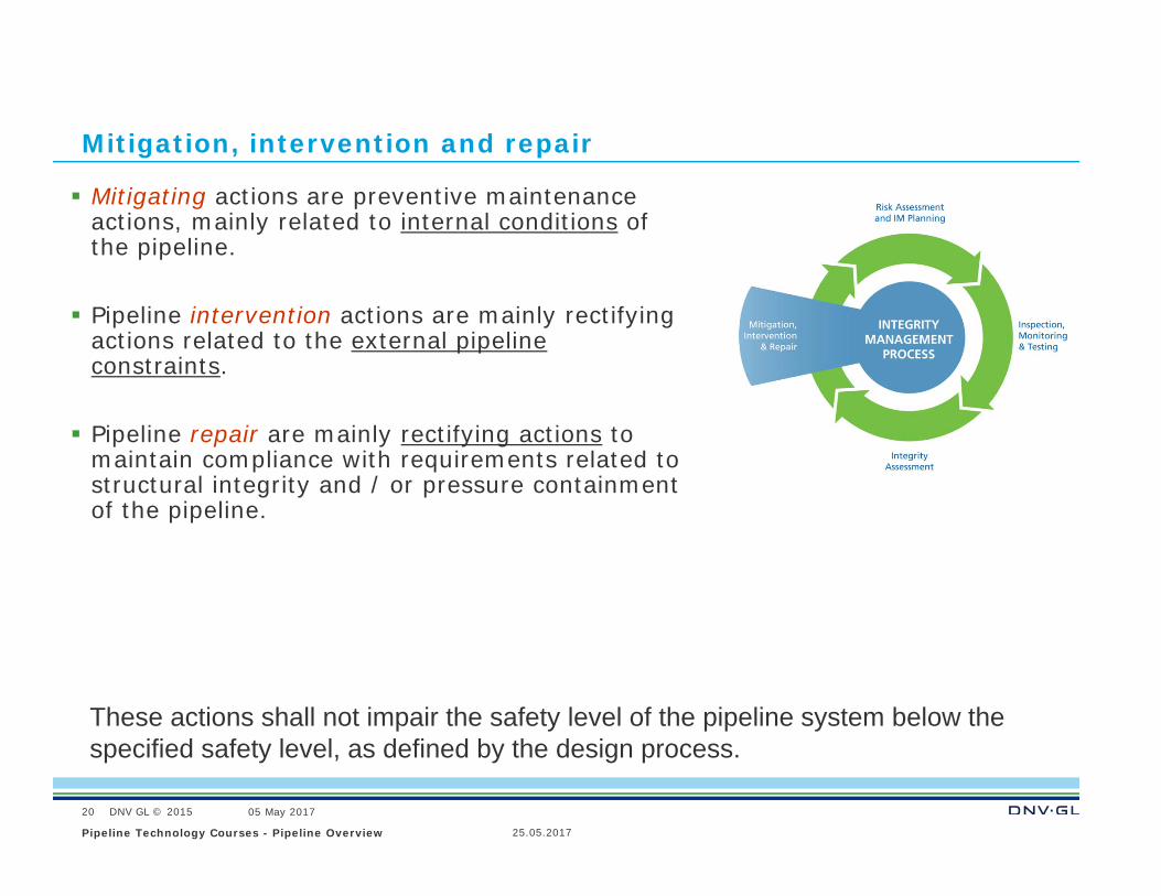
Mitigation, intervention and repair
Mitigating actions are preventive maintenance actions, mainly related to internal conditions of the pipeline.
Pipeline intervention actions are mainly rectifying actions related to the external pipeline constraints.
Pipeline repair are mainly rectifying actions to maintain compliance with requirements related to structural integrity and / or pressure containment of the pipeline.
These actions shall not impair the safety level of the pipeline system below the specified safety level, as defined by the design process.
25.05.2017Pipeline Technology Courses - Pipeline Overview
20