Embed Size (px)
Citation preview
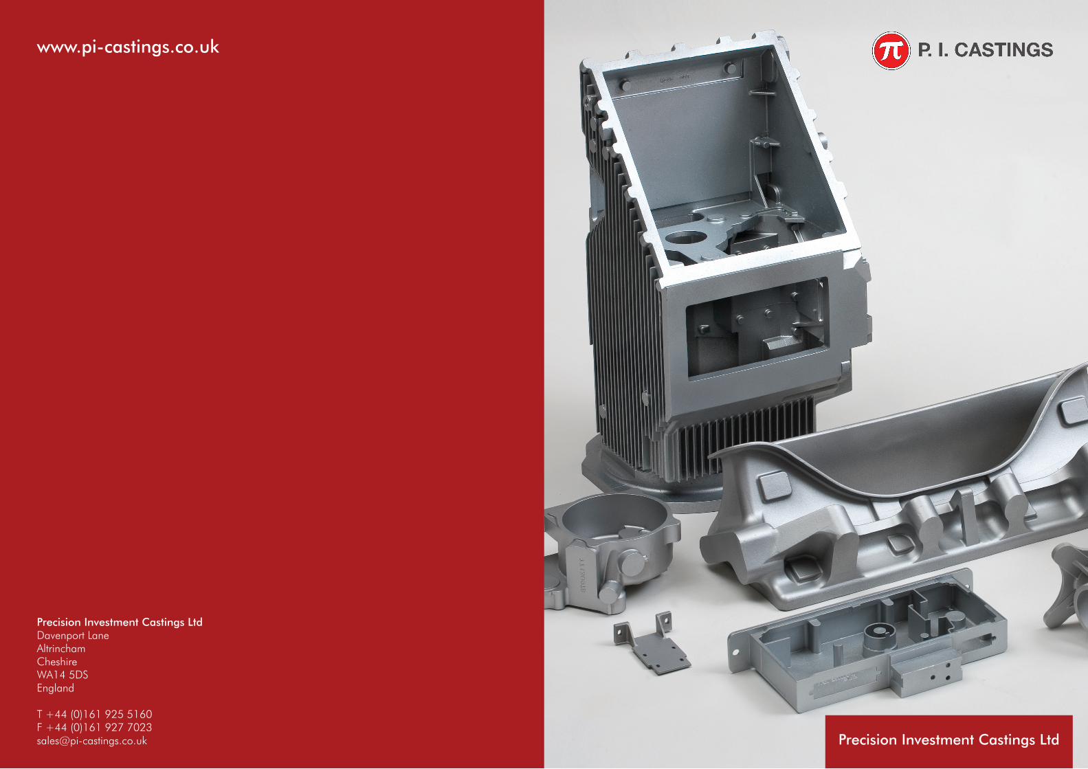
Precision Investment Castings LtdDavenport LaneAltrinchamCheshire WA14 5DSEngland
T +44 (0)161 925 5160 F +44 (0)161 927 [email protected]
www.pi-castings.co.uk
Precision Investment Castings Ltd
02 An Introduction
P. I. Castings have over 60 years experience in producing high quality precision investment castings and is one of only a few companies in Europe, who can manufacture both ferrous and non-ferrous investment castings in one production facility, to the highest standards. P. I. Castings provide a one-stop shop for aluminium or steel castings, rapid prototypes or fully machined parts in a comprehensive range of steels, stainless and high alloy materials, aluminium and copper based alloys.
“PICAST” components are used in all types of industries for general engineering, medical, electronics, aerospace and defence applications, and are produced to ISO 9001:2008 and AS9100 Aerospace Standards.
Casting Technology for Engineering Components
What can Investment Castings offer?In every industry where metal components are used, investment castings can offer advantages – to the production engineer, designer, or buyer, especially where complex shapes are required. Investment castings can eliminate most rough machining operations; give greater freedom of design; can produce shapes that are impossible to machine; provide lighter and cleaner looking components; relieve production problems by replacing assemblies with “one piece” castings – all of these advantages embodied in the widest choice of materials.
Dimensional TolerancesGenerally ± 0.125mm per 25mm (± 0.005” per inch).See detailed tables on Page 6. No casting joint lines, no draft taper.
Surface FinishA finer quality finish than most other casting processes, in the order of 3.2 microns (N8, 125CLA).
MaterialsMost types of air melted steels, aluminium and copper based alloys are produced. A detailed list of materials is given on Pages 8 and 9 including composition, mechanical properties and cross-referencedspecifications.
ToolingLow tooling costs using aluminium dies to produce accurate wax patterns. Die life is excellent and modifications are relatively easy when design changes are required.
Size RangeFrom less than 5mm to 600mm
Quality castings demand strict production procedures, rigorous quality control and the best testing and inspection facilities – all of which can be found at P. I. Castings, along with a wealth of experience in the production of investment cast components. The established policy of P. I. Castings is to provide products of consistently high quality, fit for their intended purpose and delivered in conformance with the agreed specifications.
ApprovalsP. I.Castings is registered to BS EN ISO 9001:2008, including the aerospace certification AS9100 Audited by Rolls-Royce on behalf of AECMA EASE. P. I. Castings have the prestigious NADCAP approval for non-destructive testing and welding.
Additionally, approvals are held by many leading UK and overseas companies for the supply of high integrity investment castings for aerospace and defence equipment and for general engineering applications. Investment castings are supplied to many major companies including Rolls-Royce, BAE Systems, Thales, Hamilton Sundstrand, Goodrich, Babcock Meggitt, Shorts Bombardier, Saab, Dassault, Agusta, Alenia,…..
Sample CastingsSamples are produced by a dedicated methods engineering team, using the
HIGH TECHNOLOGY FOR QUALITY CASTINGS
COMPANYPROFILE
QualityP. I. Castings is registered to BS EN ISO 9001:2008, including aerospace certification AS9100 Audited by Rolls-Royce on behalf of AECMA EASE. Approved by many international organisations and also by NADCAP for welding and non-destructive testing.
QuantityDepending on size and complexity, batch quantities as low as 25 can be economical, or high quantity requirements of several thousand permonth can be produced.
Rapid PrototypingP. I. Castings is one of only a couple of independent investment casting companies in the UK to have their own Rapid Prototyping machine. Castings canbe made direct from customer’s CAD designs,without the need for tooling– see Page 5 for details.
Machined CastingsP. I. Castings have an on-site machine shop enabling castings to be supplied in the fully finished condition, including surface treatments - see Page 4 for details.
same equipment and processes that will be used in production.All samples are dimensionally checked and may be subjected to x-ray, whether required by the customer or not, to ensure a satisfactory quality before commencing production. When a production technique has been approved, manufacturing procedures are sealed and strictly adhered to.
Dimensional InspectionFull layout inspection is carried out on all samples, with gauging or specific measurement of critical dimensions on production castings. P. I. Castings have invested in a dedicated computer system to undertake First Article Inspection Reports (FAIRs) to AS9102 Aerospace requirements.Visual inspection of every wax pattern and casting is on a 100% basis. Two co-ordinate measuring machines and a shadowgraph dimensional projector are included in the well-equipped metrology department. All measuring equipment is calibrated according to strict procedures.
Non-Destructive TestingNDT is carried out to the requirements of the customer. Equipment includes 3 x-ray sets, automatic film processing,“Real- Time” Radiography, fluorescent dye penetrant and magnetic flaw detection units. The NDT facilities are approved to NADCAP procedures.Material TestingComprehensive on-site facilities
are used to ensure that the properties of castings conform to the required specifications, including tensile and proof tests, Izod and Charpy impact tests, bend tests, and hardness checks.
Analysis of the cast metal is carried out prior to pouring and metallographic examinations are performed as required, including “cut-up” tests and decarburisation checks.
Release CertificationFull certification is issued where required and full traceability is maintained throughout the process. Records are kept on an indefinite basis.
03 Technology & Castings
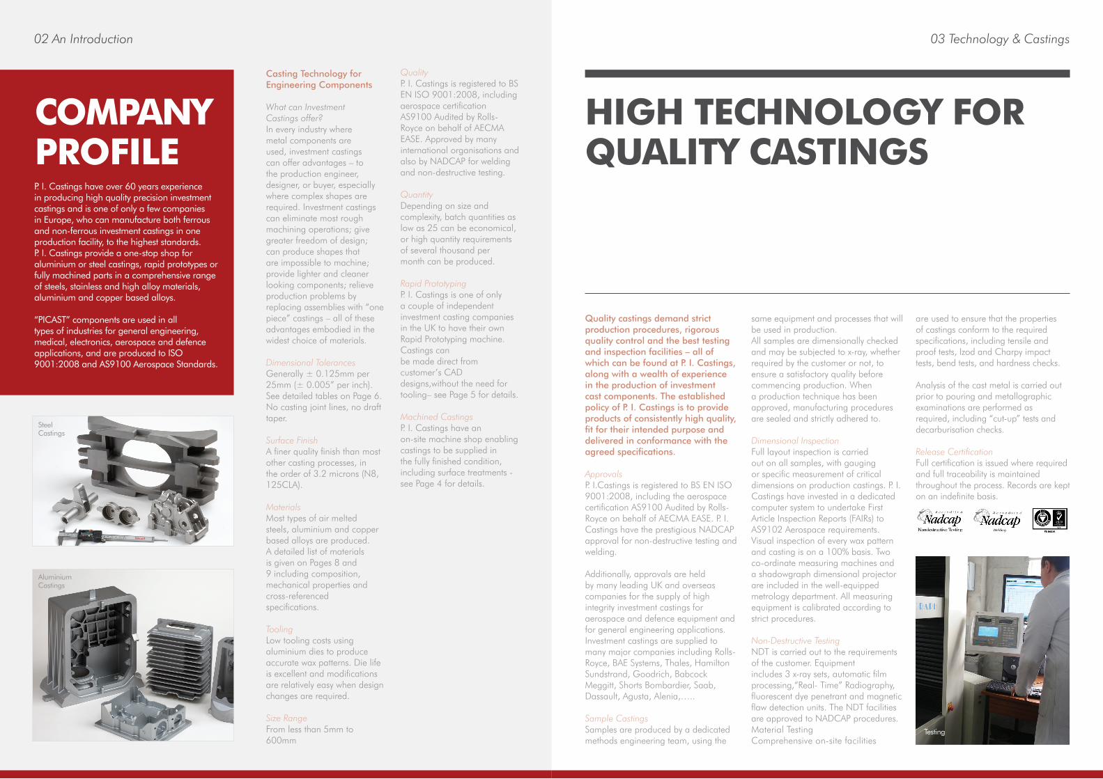
Steel Castings
AluminiumCastings
Testing
04 From Castings to Finished Components
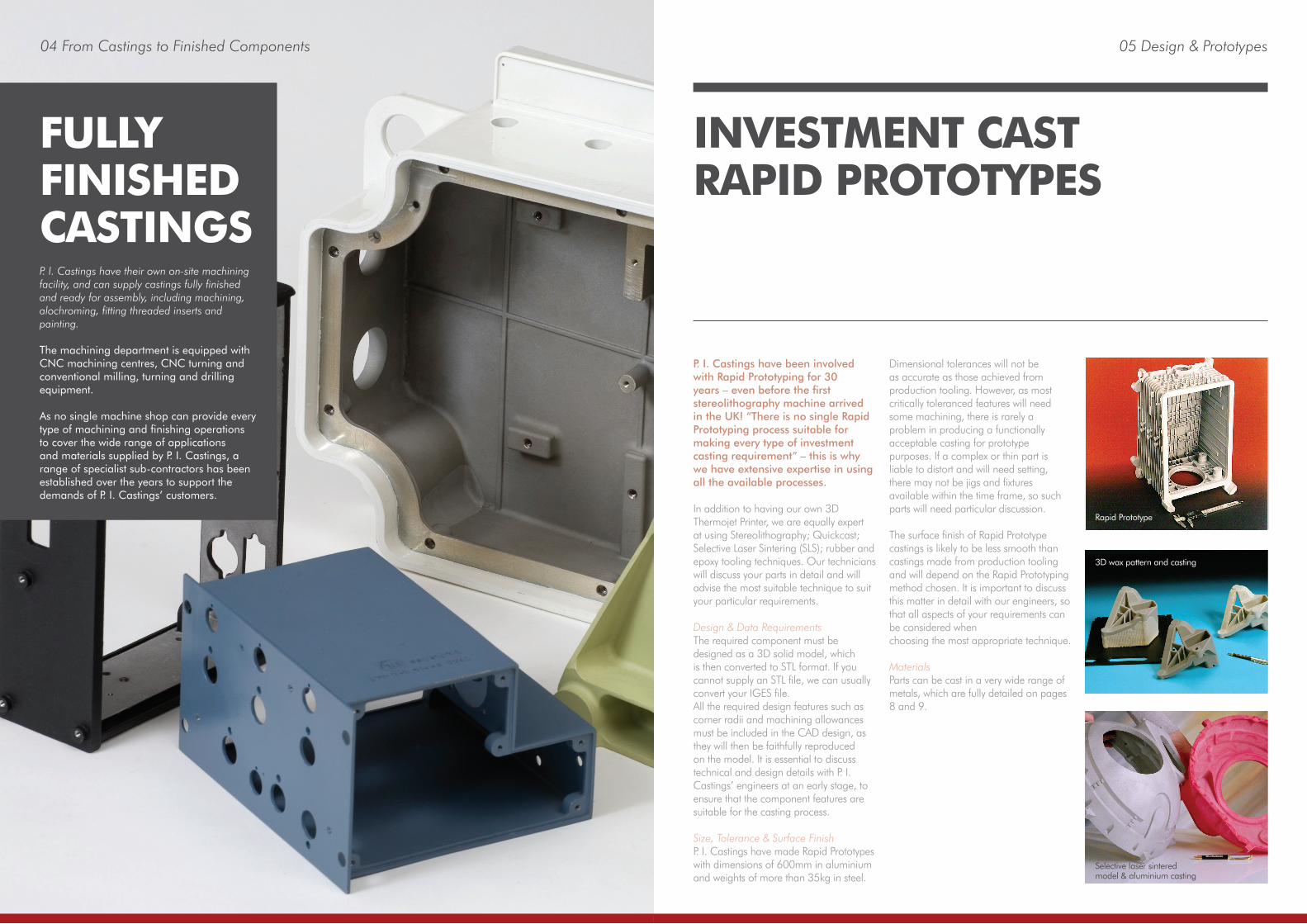
P. I. Castings have been involved with Rapid Prototyping for 30 years – even before the first stereolithography machine arrived in the UK! “There is no single Rapid Prototyping process suitable for making every type of investment casting requirement” – this is why we have extensive expertise in using all the available processes. In addition to having our own 3D Thermojet Printer, we are equally expert at using Stereolithography; Quickcast; Selective Laser Sintering (SLS); rubber and epoxy tooling techniques. Our technicians will discuss your parts in detail and will advise the most suitable technique to suit your particular requirements.
Design & Data RequirementsThe required component must be designed as a 3D solid model, which is then converted to STL format. If you cannot supply an STL file, we can usually convert your IGES file.All the required design features such as corner radii and machining allowances must be included in the CAD design, as they will then be faithfully reproduced on the model. It is essential to discuss technical and design details with P. I. Castings’ engineers at an early stage, to ensure that the component features are suitable for the casting process.
Size, Tolerance & Surface Finish P. I. Castings have made Rapid Prototypes with dimensions of 600mm in aluminium and weights of more than 35kg in steel.
Dimensional tolerances will not be as accurate as those achieved from production tooling. However, as most critically toleranced features will need some machining, there is rarely a problem in producing a functionally acceptable casting for prototype purposes. If a complex or thin part is liable to distort and will need setting, there may not be jigs and fixtures available within the time frame, so such parts will need particular discussion.
The surface finish of Rapid Prototype castings is likely to be less smooth than castings made from production tooling and will depend on the Rapid Prototyping method chosen. It is important to discuss this matter in detail with our engineers, sothat all aspects of your requirements can be considered whenchoosing the most appropriate technique.
MaterialsParts can be cast in a very wide range of metals, which are fully detailed on pages 8 and 9.
INVESTMENT CAST RAPID PROTOTYPES
Selective laser sintered model & aluminium casting
Rapid Prototype
3D wax pattern and casting
05 Design & Prototypes
P. I. Castings have their own on-site machining facility, and can supply castings fully finished and ready for assembly, including machining, alochroming, fitting threaded inserts and painting.
The machining department is equipped with CNC machining centres, CNC turning and conventional milling, turning and drilling equipment.
As no single machine shop can provide every type of machining and finishing operations to cover the wide range of applications and materials supplied by P. I. Castings, a range of specialist sub-contractors has been established over the years to support the demands of P. I. Castings’ customers.
FULLY FINISHED CASTINGS
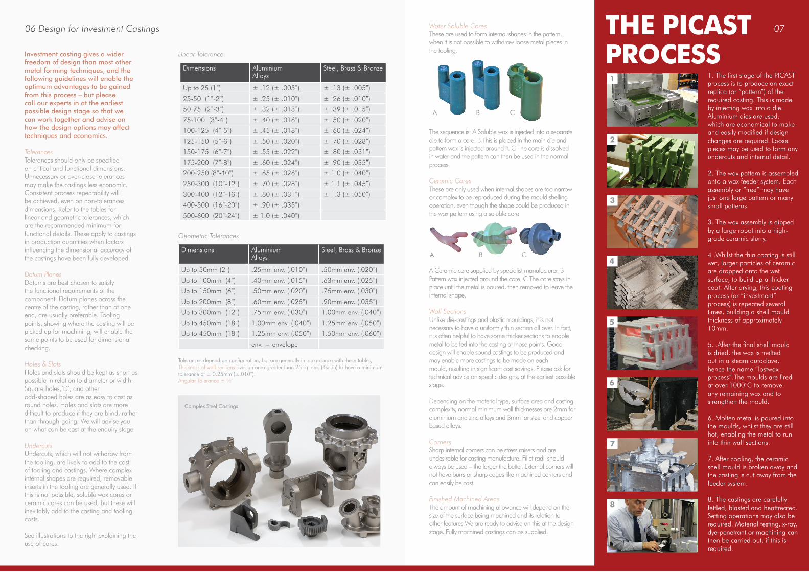
Water Soluble CoresThese are used to form internal shapes in the pattern, when it is not possible to withdraw loose metal pieces in the tooling.
The sequence is: A Soluble wax is injected into a separate die to form a core. B This is placed in the main die and pattern wax is injected around it. C The core is dissolved in water and the pattern can then be used in the normal process.
Ceramic CoresThese are only used when internal shapes are too narrow or complex to be reproduced during the mould shelling operation, even though the shape could be produced in the wax pattern using a soluble core
A Ceramic core supplied by specialist manufacturer. B Pattern wax injected around the core. C The core stays in place until the metal is poured, then removed to leave the internal shape.
Wall SectionsUnlike die-castings and plastic mouldings, it is not necessary to have a uniformly thin section all over. In fact, it is often helpful to have some thicker sections to enable metal to be fed into the casting at those points. Good design will enable sound castings to be produced and may enable more castings to be made on eachmould, resulting in significant cost savings. Please ask for technical advice on specific designs, at the earliest possible stage.
Depending on the material type, surface area and casting complexity, normal minimum wall thicknesses are 2mm for aluminium and zinc alloys and 3mm for steel and copper based alloys.
CornersSharp internal corners can be stress raisers and are undesirable for casting manufacture. Fillet radii should always be used – the larger the better. External corners will not have burrs or sharp edges like machined corners and can easily be cast.
Finished Machined AreasThe amount of machining allowance will depend on the size of the surface being machined and its relation to other features.We are ready to advise on this at the design stage. Fully machined castings can be supplied.
Investment casting gives a wider freedom of design than most other metal forming techniques, and the following guidelines will enable the optimum advantages to be gained from this process – but please call our experts in at the earliest possible design stage so that we can work together and advise on how the design options may affect techniques and economics.
TolerancesTolerances should only be specified on critical and functional dimensions. Unnecessary or over-close tolerances may make the castings less economic. Consistent process repeatability will be achieved, even on non-tolerances dimensions. Refer to the tables for linear and geometric tolerances, which are the recommended minimum for functional details. These apply to castings in production quantities when factors influencing the dimensional accuracy of the castings have been fully developed.
Datum PlanesDatums are best chosen to satisfy the functional requirements of the component. Datum planes across the centre of the casting, rather than at one end, are usually preferable. Tooling points, showing where the casting will be picked up for machining, will enable the same points to be used for dimensional checking.
Holes & SlotsHoles and slots should be kept as short as possible in relation to diameter or width. Square holes,‘D’, and other odd-shaped holes are as easy to cast as round holes. Holes and slots are more difficult to produce if they are blind, rather than through-going. We will advise you on what can be cast at the enquiry stage.
UndercutsUndercuts, which will not withdraw from the tooling, are likely to add to the cost of tooling and castings. Where complex internal shapes are required, removable inserts in the tooling are generally used. If this is not possible, soluble wax cores or ceramic cores can be used, but these will inevitably add to the casting and tooling costs.
See illustrations to the right explaining the use of cores.
Linear Tolerance
Geometric Tolerances
Tolerances depend on configuration, but are generally in accordance with these tables, Thickness of wall sections over an area greater than 25 sq. cm. (4sq.in) to have a minimum tolerance of ± 0.25mm (±.010”).Angular Tolerance ± ½°
06 Design for Investment Castings
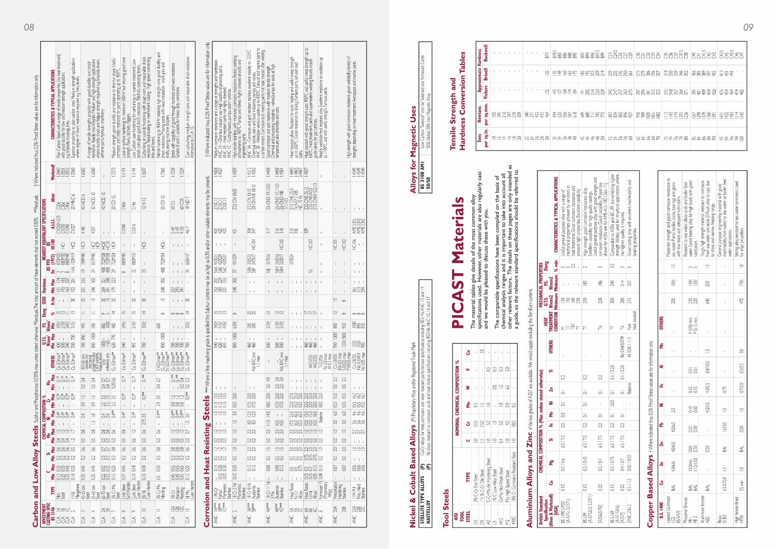
Dimensions Aluminium Alloys
Steel, Brass & Bronze
Up to 25 (1”) ± .12 (± .005”) ± .13 (± .005”)25-50 (1”-2”) ± .25 (± .010”) ± .26 (± .010”)50-75 (2”-3”) ± .32 (± .013”) ± .39 (± .015”)75-100 (3”-4”) ± .40 (± .016”) ± .50 (± .020”)100-125 (4”-5”) ± .45 (± .018”) ± .60 (± .024”)125-150 (5”-6”) ± .50 (± .020”) ± .70 (± .028”)150-175 (6”-7”) ± .55 (± .022”) ± .80 (± .031”)175-200 (7”-8”) ± .60 (± .024”) ± .90 (± .035”)200-250 (8”-10”) ± .65 (± .026”) ± 1.0 (± .040”)250-300 (10”-12”) ± .70 (± .028”) ± 1.1 (± .045”)300-400 (12”-16”) ± .80 (± .031”) ± 1.3 (± .050”)400-500 (16”-20”) ± .90 (± .035”)500-600 (20”-24”) ± 1.0 (± .040”)
Dimensions Aluminium Alloys
Steel, Brass & Bronze
Up to 50mm (2”) .25mm env. (.010”) .50mm env. (.020”)Up to 100mm (4”) .40mm env. (.015”) .63mm env. (.025”)Up to 150mm (6”) .50mm env. (.020”) .75mm env. (.030”)Up to 200mm (8”) .60mm env. (.025”) .90mm env. (.035”)Up to 300mm (12”) .75mm env. (.030”) 1.00mm env. (.040”)Up to 450mm (18”) 1.00mm env. (.040”) 1.25mm env. (.050”)Up to 450mm (18”) 1.25mm env. (.050”) 1.50mm env. (.060”)
env. = envelope
1. The first stage of the PICAST process is to produce an exact replica (or “pattern”) of the required casting. This is made by injecting wax into a die.Aluminium dies are used, which are economical to make and easily modified if design changes are required. Loose pieces may be used to form any undercuts and internal detail.
2. The wax pattern is assembled onto a wax feeder system. Each assembly or “tree” may have just one large pattern or many small patterns.
3. The wax assembly is dipped by a large robot into a high-grade ceramic slurry.
4 .Whilst the thin coating is still wet, larger particles of ceramic are dropped onto the wet surface, to build up a thicker coat. After drying, this coating process (or “investment” process) is repeated several times, building a shell mould thickness of approximately 10mm.
5. .After the final shell mould is dried, the wax is melted out in a steam autoclave, hence the name “lostwax process”.The moulds are fired at over 1000°C to remove any remaining wax and to strengthen the mould.
6. Molten metal is poured into the moulds, whilst they are still hot, enabling the metal to run into thin wall sections.
7. After cooling, the ceramic shell mould is broken away and the casting is cut away from the feeder system.
8. The castings are carefully fettled, blasted and heattreated. Setting operations may also be required. Material testing, x-ray, dye penetrant or machining can then be carried out, if this is required.
A
A
B
B
C
C
THE PICAST PROCESS1
2
3
4
5
6
7
8
Complex Steel Castings
07
08 09


![PTMC: MICROFABRICATION & STEREOLITHOGRAPHY · Stereolithography is a form of prototyping that has been shown to be very versatile with highest accuracy and precision.[11] Stereolithography](https://img.pdfslide.us/doc/110x75/605ef4b2b0307a40e8391640/ptmc-microfabrication-stereolithography-stereolithography-is-a-form-of-prototyping.jpg)