Embed Size (px)
Citation preview
CHAPTER 4
OIL AND GAS MANAGEMENT PRACTICES
TABLE OF CONTENTS
Pages
Introduction ..............................................................................................................4-1
SECTION I
A. Guidelines for a Preparedness, Prevention and Contingency (PPC) Plan for Oil and Gas Development ................................................................ 4-2
1. Description of Operations ..............................................................................4-2
2. Pollution Prevention Measures ......................................................................4-3
3. Waste Disposal Methods ................................................................................4-3
4. Pollution Incident Response ..........................................................................4-4
5. Narrative Section.............................................................................................4-4
6. PPC Schedule ..................................................................................................4-4
B. Pollution Prevention Practices ........................................................................4-4
1. Drilling and Completion Procedures That Reduce Fluid Volumes ..........4-5
2. Stimulation Procedures That Reduce Fluid Volumes .................................4-7
3. Water-Oil Ratio Improvement Chemical.....................................................4-8
4. Recycling of Produced Fluid .........................................................................4-8
5. Use of Tanks or Containers .............................................................................4-8
6. Source Reduction Opportunities ..................................................................4-8
550-0300-001 / October 30, 2001 / Chapter 4, Page i
SECTION II SITE PLANNING AND EROSION AND SEDIMENT CONTROL
A. Planning the Access Road and Well Site.......................................................4-9
1. Planning the Access Road to the Well Site .............................................4-9
2. Planning the Well Site ...............................................................................4-10
3. Planning Activities at the Well Site After Drilling....................................4-11
4. Tank and Separator Pads.........................................................................4-11
5. Electric and Pipeline Rights-of-Way........................................................4-11
B. Erosion and Sediment Control - Introduction ..............................................4-12
C. Erosion and Sediment Control Plan..............................................................4-12
D. Best Management Practices for Well Sites ..................................................4-24
E. Best Management Practices for Access Roads..........................................4-36
F. Best Management Practices for Pipelines ...................................................4-52
G. Revegetation Best Management Practices.................................................4-61
H. Best Management Practices for Special Protection Watersheds..............4-68
SECTION III
Water Obstructions and Encroachments................................................................ 70
SECTION IV – DRILLING, ALTERING AND COMPLETING A WELL
A. Notification and Local Ordinances ................................................................. 73
B. Safety Considerations....................................................................................... 73
1. Wells In a Hydrogen Sulfide Area............................................................... 73
2. Casing Requirements and Recommendations....................................... 73
3. Lost Radioactive Sources ............................................................................ 74
550-0300-001 / October 30, 2001 / Chapter 4, Page ii
C. Casing Design Criteria...................................................................................... 74
1. Fresh Ground-Water Protective Casing .................................................... 74
2. Underground Gas Storage Field Casing................................................... 75
3. Coal Protective Casing ............................................................................... 75
4. Alternate Methods ....................................................................................... 75
5. Defective Casing or Cementing................................................................ 75
D. Fluids Management During Drilling, Completing and Altering a Well ......... 76
SECTION V WASTE MANAGEMENT DURING DRILLING, OPERATING AND PLUGGING A WELL
A. Waste Management Hierarchy ....................................................................4-77
B. Land Application of Tophole Water .............................................................4-77
C. Disposal of Drill Cuttings From Above the Casing Seat ..............................4-78
D. Disposal of Drill Cuttings From Below the Casing Seat ...............................4-78
E. Disposal of Residual Waste Disposal ............................................................4-78
F. Disposal Wells or Injection Wells...................................................................4-79
G. Treatment and Discharge to Surface Waters ..............................................4-80
H. Discharge to an Existing Treatment Facility.................................................4-80
I. Discharge to a Pretreatment Facility............................................................4-81
J. Roadspreading of Brine for Dust Control and Road Stabilization ..............4-81
K. Evaporation ....................................................................................................4-84
L. Off-site Solids Disposal...................................................................................4-84
M. Residual Wastes Transfer Stations and Residual Waste Processing Facilities.......................................................................................4-84
N. Transportation of Wastes ...............................................................................4-85
550-0300-001 / October 30, 2001 / Chapter 4, Page iii
SECTION VI WELL SITE RESTORATION
A. Well Site Restoration.......................................................................................4-87
B. Well Site Restoration Report ..........................................................................4-87
SECTION VII WELL OPERATION
A. General Provisions .........................................................................................4-88
B. Oil Storage Tanks and Containment (Dikes) ...............................................4-88
C. Fluids Management During Operation, Servicing and Plugging Activities .........................................................................................4-89
D. Annual Well and Waste Production Report .................................................4-89
E. Pipeline Operation and Maintenance.........................................................4-90
F. Oil and Gas Separators .................................................................................4-91
SECTION VIII – REPORTS
A. Reports Required of Oil and Gas Operators................................................4-92
SECTION IX INACTIVE STATUS AND WELL PLUGGING
A. Inactive Status and Abandonment ..............................................................4-94
B. Plugging Abandoned or Orphan Wells........................................................4-94
1. Well Plugging .............................................................................................4-94
2. Reporting Requirements...........................................................................4-94
C. Rehabilitating Abandoned or Orphan Wells ...............................................4-95
SECTION X UNDERGROUND GAS STORAGE
A. Requirements Under Act 223, the Oil and Gas Act ....................................4-96
B. Requirements Under 25 Pa. Code Chapter 78 ............................................4-96
550-0300-001 / October 30, 2001 / Chapter 4, Page iv

CHAPTER 4
INTRODUCTION
OIL AND GAS MANAGEMENT PRACTICES
The purpose of this chapter is to describe the management practices, options and regulations which will minimize or eliminate potential environmental impact from oil and gas development, and provide a measure of safety when drilling and operating wells. These procedures reflect the best practices available to the industry that consider cost-effectiveness, environmental protection and safety.
The organization of this chapter follows the life of a well. It begins with discussions of preventing pollution, continues into site preparation, erosion and sediment control drilling and waste disposal, and further to well operation procedures, and finally to well plugging and site reclamation. The chapter concludes with an overview of gas storage reservoir maintenance. For each phase of well development and operation, the basic requirements from the relevant laws and regulations are presented, followed by a discussion of practical recommendations of how to stay in compliance.
Not all of the practices and options outlined will be appropriate or economically feasible for all operators. You should select those practices applicable to your operations. In addition, you are encouraged to routinely evaluate your operating procedures. When appropriate, you should incorporate the new procedures as they are perfected by the industry. The Department intends that the chapter and your operations be as flexible and dynamic as the changing technology by choosing “state of the art“ practices resulting in the most efficient and environmentally sound oil and gas operations.
550-0300-001 / October 30, 2001 / Chapter 4, Page 1
SECTION I
A. Guidelines For A Preparedness, Prevention And Contingency (PPC) Plan For Oil And Gas Development
There is widespread agreement that prevention of an environmental problem is easier and less expensive than cleaning up the problem after it has occurred. The Department’s rules and regulations 25 Pa. Code §§ 78.55 and 91.34 (See Appendix 1) recognize the value of careful planning to prevent pollution and require that all persons engaged in activities which have the potential for causing pollution of the waters of the Common-wealth take all necessary measures to prevent polluting substances from reaching waters of the Commonwealth. Operators may satisfy the pollution prevention and control and disposal plan requirements specified in 25 Pa. Code §§78.55 and 91.34 by preparing and implementing a PPC plan.
The first objective in preparing and implementing a Preparedness, Prevention and Contingency (PPC) plan is for the operator to review his operations and identify all the pollutional substance and wastes, both solid and liquid, that will be used or generated, and identifying the methods for control and disposal of those substances or wastes. The second objective of a PPC plan involves recognizing that accidents and unexpected conditions do occur that would require an immediate response to mitigate any detrimental effects from those accidents or conditions, and planning the actions to be taken to prevent pollution substances from reaching the waters of the Commonwealth.
The following guidelines for developing a PPC plan have been developed to assist the operator in satisfying the requirements of the Department’s rules and regulations. The plan should contain site specific information for each site or project, and upon request, a copy of the PPC plan is required to be submitted to the Department.
Each plan is to include the following:
1. Description of Operations
a. Include the company or corporation name and address, responsible officials for the operation, and chain-of-command within the company. Include a 24-hour phone number of the person to contact for emergency situations.
b. Identify the location(s) of the operation(s) on maps by county and township. Also, identify each well location by lease, farm name, project or other distinguishable description and indicate if tank batteries or storage or handling areas are utilized at the location. In describing the tanks or the storage or handling areas, indicate the tank number and type and volume of substances and wastes that are encountered, used, handled or stored. Include the nearest field office responsible for each of the operations.
c. Identify the type of operation, whether oil, gas or both. Identify the activity (primary, secondary, tertiary production or exploratory, etc.).
d. If the operation involves drilling, describe your method of drilling the wells (air rotary, fluid rotary, cable tool, etc.).
550-0300-001 / October 30, 2001 / Chapter 4, Page 2
2. Pollution Prevention Measures
a. List the chemicals or additives utilized and the different wastes generated during the drilling, stimulation, production, plugging and servicing phases of your operation. Include safety and health information, (e.g. Material Safety Data Sheets), cleanup procedures, toxicological data and waste chemical characteristics. The approximate quantities of each material and the method of storage (sack, barrels, tanks, etc.) should be specified.
b. An assessment of the likelihood and consequences of a spill involving the materials utilized during any phase of the operation must be addressed, including the potential impact or downstream water supplies and public water wells in the area.
c. The method of containment for spilled or lost materials must be addressed. Also, the method of containment for the fluids, residual wastes, and drill cuttings mentioned in subsection a. above must be addressed. If impoundments are utilized for containment of these materials, all information submitted for the construction or use of impoundments for oil and gas activities should be cross-referenced here. In the PPC plan, contingency planning must be made for the failure of impoundments, the production of wastes in excess of the impound-ment’s capacity, and similar problems which could occur.
d. Protection from external factors. The impact on your operations from the unauthorized acts of third parties, strikes, floods, power failures, and similar problems must be taken into consideration in development of the plan. Locking valves, special wrenches, fences, and other security measures are examples of measures which could be taken by your company.
e. Preventative Maintenance - The availability of critical replacement parts, maintenance inspection routines, and collection line replacement schedules are examples of preventative maintenance.
f. Personnel Training Programs - The training of all company personnel and contracted employees, regarding the pollution prevention measures described in the plan, must be discussed in the plan.
3. Waste Disposal Methods
Identify the method(s) of wastewater, drill cuttings and solid or residual waste control, disposal or reuse for the different waste generated. Permitted facilities to be used or the need for separate approvals should be incorporated or referenced. If a disposal facility not at the well site is used, the name and address of the facility should be identified along with the hauler and types of wastes that can be disposed of at the facility.
4. Pollution Incident Response
a. Equipment available for cleanup of a given spill must be listed. In this section, a list of the equipment which the company maintains should be included, along
550-0300-001 / October 30, 2001 / Chapter 4, Page 3
with its storage location and a description of how this equipment can be deployed where needed in a prompt manner.
b. Outside cleanup contractors may be necessary to meet pollution incident responses which your company cannot directly handle. These companies should be listed with their cleanup abilities, addresses, telephone numbers and contact persons. Backup wastewater hauling firms and disposal sites should be included on this list.
c. Reporting Procedure - The company representative responsible for reporting potential or existing pollution incidents should be indicated. The PPC plan must contain a list of the agencies to be notified by telephone should an incident, or the threat of an incident, occur. These agencies must include: DEP Regional Office, both business hour and 24-hour numbers (See Chapter 1 for the appropriate DEP office) and EPA-800-424-8802. Downstream water users (industrial intakes, public water supplies, etc.) must be identified, and contact persons and telephone numbers must be included. Also, it is recommended that the Pennsylvania Fish and Boat Commission (See Appendix 1 for the Commission district offices) be notified. There are additional conservation well reporting requirements for fires, explosions, or spills of oil or gas which are required by 25 Pa. Code § 79.15 of the Rules and Regulations promulgated under the Oil and Gas Conservation Law (see Appendix 1).
5. Narrative Section
A narrative section must be included in the PPC plan which reviews the company’s history of pollution incidents and corrective actions taken. The potential for a similar pollution problem occurring at the proposed operation site must be evaluated, and corrective actions must be addressed in the plan to prevent a recurrence of a similar incident.
6. PPC Schedule
A schedule must be included in the PPC plan for implementation of the requirements of the completed plan. The plan must also be revised prior to implementing a change to the practices identified, and updated with revisions and history after an incident occurs.
B. Pollution Prevention Practices
The operator is encouraged to incorporate pollution prevention practices into daily operations whenever possible. Pollution prevention involves eliminating or reducing the waste generated through process changes, source reduction, substitution, new technology and reuse. Pollution prevention not only lessens the impact on the environment, but also can lower the cost to industry for disposal and lessen liability.
One of the most efficient waste fluid management alternatives is fluid volume reduction and fluid reuse. Any fluid that can be reused or recycled represents a savings in disposal costs and is of benefit to the environment. Although the procedures offered may not be appropriate for all operations, every operator is encouraged to review their drilling,
550-0300-001 / October 30, 2001 / Chapter 4, Page 4
stimulation, and production procedures. Where appropriate, the operator may wish to incorporate techniques to reduce waste fluid generation.
In other chapters of this manual, the requirements in various laws, both state and federal, are discussed, along with procedures for permit application and approval of waste disposal practices. A number of suggested alternative practices are as follows:
1. Drilling and Completion Procedures That Reduce Fluid Volumes
The following procedures have been demonstrated to be effective in fluid volume reduction in Pennsylvania during the drilling and completion phases:
a. Ground Water Protective Casing (Surface Casing)
The major purposes for installing ground water protective casing are to keep ground water out of the well while drilling and during production, protect ground water quality and avoid dewatering shallow aquifers and insure effective control of the well at all times. Ground water protective casing is to be set deep enough to shut off all fresh ground water and cemented in accordance with 25 Pa. Code Sections 78.81-78.86.
b. Continuous Air Drilling
When saline or fresh water is encountered during drilling, the well should be completed as rapidly as possible to minimize the time water is being blown back to the surface. Drilling on a 24-hour schedule to eliminate daily blow off of water accumulated in the well bore and doing everything possible to reduce the likelihood of an extra "trip" can result in substantial savings in terms of water blown to the pit. When water is encountered in an excessive amount, it may be advantageous, from a fluid reduction position, to stop drilling and isolate the water zone by pressure plugging (see 1.e.) or casing off the source horizon (see 1.d).
c. Cable Tool Drilling
In some situations, cable tool drilling may be preferred to air rotary drilling to limit the volume of water brought to the surface. Although the fresh ground water zone is exposed for a longer time, the only surface discharge expected during cable tool drilling occurs when the cuttings are bailed out of the hole.
d. Intermediate Strings
In some areas, while drilling below the surface casing, specific geologic horizons or zones may produce large quantities of brine water during air drilling. While it may, at times, be possible to overcome this water with large air volumes or pressures, it may be desirable to shut these zones off with intermediate strings of casing. In this procedure, the subject formation or zone is fully penetrated, a string of pipe is placed in the hole, and a seal established at the bottom of the pipe. The seal may be made permanent by cementing the annular space between the well bore and the intermediate casing back to the surface, or spotting cement over the salt water producing zone.
550-0300-001 / October 30, 2001 / Chapter 4, Page 5
e. Plugging Water Bearing Zone
Another technique that can be used to isolate salt water producing zones involves cementing off the zone. In this procedure, cement or another water blocking material, is placed over the subject zone. This may be done under elevated pressure to promote penetration of the formation with the cement or other water blocking material. This technique is usually not as successful as using intermediate casing.
f. Fluid or Mud Drilling
For deep wells or in areas where it is anticipated the operator will encounter large volumes of water, drilling with fluid or mud can be very effective in reducing the volume of wastewater produced. When a closed loop system is used, the drilling fluid is continuously recycled down the hole to remove cuttings to the surface. The high hydrostatic head in the well bore prevents large inflows of formation water that might be otherwise blown to the surface during air drilling. Although mud or fluid drilling may represent an effective water control alternative for drilling, this practice may result in the additional problem of mud disposal.
In addition to the above, the closed loop system can be successfully implemented utilizing only the fresh water. Since there have been no drilling muds or additives introduced into the system, the remaining water may meet discharge requirements and could possibly be land applied.
Another procedure commonly known as “aeration drilling,” combines both air and fluid drilling techniques. This procedure takes advantage of fluid drilling (low amounts of water being returned to surface) and air drilling (rapid penetration rate). As described above the high hydrostatic column will prohibit large inflows of water, but at the same time the injection of air will facilitate the removal of drill cuttings to surface. This accomplished two goals: 1) limiting the time that the aquifers are exposed to drilling conditions; and 2) limiting the amount of water to be brought to the surface, thus lessening the potential of diminution of fresh groundwater aquifers . This can be extremely important when conditions are such that an operator would be setting casing under Section 78.83(C). This procedure would substantially reduce the commingling time these aquifers would be exposed. Under the same conditions, all of the above mentioned drilling procedures could be presumed optimal compared to cable tool drilling. As described in the introduction of this manual, choosing “state of the art“ and “common sense“ practices are, in the majority of cases, the most efficient and environmentally sound.
2. Stimulation Procedures That Reduce Fluid Volumes
A number of techniques are available to reduce the waste-fluid volume generated as a result of hydrofracturing. Several of these involve utilization or reutilization (recycling) of previously-generated fluids. Other methods involve reduction of fluid volumes required to treat the well.
550-0300-001 / October 30, 2001 / Chapter 4, Page 6
a. Re-Use of Frac Water
By containing the flow back from a well after hydrofracturing, it may be possible to re-use some of the water on successive stages of the same job or on other wells. On-site pretreatment, such as flocculation, settling or filtration may be necessary to re-use the water. This activity has a dual advantage in that: 1) flow-back water is carefully controlled and not allowed to spill onto the land surface or discharge to streams, and 2) the total volume of water required is reduced. The re-use of frac water has caused formation plugging and may not be acceptable for every operation.
b. Use of Production Brines in Frac
In some situations, it may be possible to utilize production brine to hydrofracture wells. The utilization of brines in this manner reduces the total volume of wastewater generated. Again, pretreatment may be necessary as formation plugging may result.
c. Use of Pit Water To Frac
Similar to utilizing production brine, pit water which consists of drilling and perhaps frac water may in some applications be utilized for stimulation. Again, pre-treatment may be necessary.
d. Use of Efficient Frac Fluids
In relatively recent years, the service companies in the Appalachian Basin have brought into use hydrofracturing fluid systems that are so efficient in transporting and depositing the propping agent in the created fracture that smaller volumes of fluid can achieve the same results. One example is the foam frac. The fluid consists of a gas and water phase with large concentrations of surfactants. This system can reduce the water requirements by more than 75% over conventional gel or water fracs. Sand concentrations in excess of 15 pounds per gallon of water are possible. While this system is not used in open hole completions, because of the danger involved, it is an effective fluid reduction technique in cased wells. Although it is the more expensive method, the great reduction in spent fracturing fluid, the reduction in water handling, clean up and storage and the reduced reservoir damage are definite benefits. The results of this type of fracturing may be unsatisfactory in some formations.
550-0300-001 / October 30, 2001 / Chapter 4, Page 7
3. Water-Oil Ratio Improvement Chemical
Although experimental and relatively new on the market, water-oil ratio improvement chemicals have been developed which, when applied to certain producing formations may improve profitability by decreasing water production and permitting additional oil to be produced. A polymeric material, which decreases the relative permeability of the rock to water as compared to oil, is introduced into the formation by pumping under pressure. Thus, a more favorable water-to-oil ratio is achieved.
4. Recycling of Produced Fluid
Perhaps the best example of efficient reuse of produced water is in recycling or closed-loop enhanced recovery operations. Some water-floods currently operating in Pennsylvania collect all water produced from the wells and reinject the fluid back through the system. Under this concept, no discharges are planned to ground or surface water. In some situations, it may be possible to use water generated at one location as make-up water at a closed-loop recycling operation. Although more expensive than using fresh water, it may be more cost effective than treatment and discharge to surface water. Operators considering this technique should be aware of the possible increased treatment costs and decreased oil recovery.
5. Use of Tanks or Containers
Depending on costs of brine disposal and amount of precipitation, an operator may find the use of enclosed steel or fiberglass tanks or containers for the collection of frac water and/or produced water to be feasible. As well as reducing the amount of fluid to be disposed, the use of tanks and containers can reduce environmental problems associated with impoundments. Tanks and containers should be leak free, structurally sound and equipped with an emergency overflow control facility.
6. Source Reduction Opportunities
The careful selection of chemical products used in exploration and production can reduce the toxicity of the wastes. Potential product substitution candidates include biocides and corrosion inhibitors, coagulants, dispersants, emulsion breakers, scale and paraffin inhibitors, gas sweetening and dehydration agents, catalysts, and pipe dope. Similarly, the careful selection of drilling fluids and additives can minimize the toxicity of drilling wastes.
In addition to product substitution, source reduction can be achieved by minimizing the generation of clean-up wastes by management of production facilities and spill and release prevention techniques. These techniques include good housekeeping practices, routine inspections of production, equipment evaluation of potential spills and mitigation measures taken to prevent their occurrence, equipment innovations, and containment systems.
550-0300-001 / October 30, 2001 / Chapter 4, Page 8
SECTION II.
SITE PLANNING AND EROSION AND SEDIMENT CONTROL
A. Planning the Access Road and Well Site
1. Planning the Access Road to the Well Site.
a. The surface owner and the oil and gas operator should agree upon and then carefully plan the use of any existing road and the location of any road which must be constructed. The agreement and the plan should include how, in accordance with these guidelines, the road will be constructed, maintained and reclaimed.
b. Will you need a road use permit either from the state, township, municipality, or national forest? Where roads or bridges have weight limits, you may have to post a bond to acquire access.
c. Are you required to obtain a highway occupancy permit to build an exit from the public road to the lease road? If in doubt, contact the Pennsylvania Department of Transportation District Office.
d. Land use restrictions and zoning under local municipal code may affect the location of your well site.
e. If your access road crosses a stream or is located in the floodway, you will need an encroachment permit from DEP if the upstream drainage area is greater than 100 acres. Also, if the access road crosses a wetland, an encroachment permit is needed.
f. If the well is to be drilled in wet weather, or the lease road is likely to be muddy, a stone loading and unloading pad should be constructed off the public road so bulldozers, trucks and equipment will not have to encroach on the public road and mud will not be tracked on to the public road.
g. Guidelines for Choosing the Lease Road Corridor:
(1) Avoid springs, seep areas and wet areas, if possible; and stay as far from streams as practicable.
(2) Use less than 10 percent grades where possible.
(3) Select a corridor that will provide the best road surface considering the season in which the well is to be drilled. Will the road bear the weight of the proposed vehicles?
(4) When feasible, all electric lines and pipelines should be buried within the road corridor.
550-0300-001 / October 30, 2001 / Chapter 4, Page 9
(5) Permanent access roads should be built with a crowned roadway and an adequate stone surface and drainage system. It will pay to do so in the long run.
(6) Plan to scrape off and stockpile the topsoil for restoration after drilling.
(7) The road base should be checked for unstable soils. Consider using geotextile fabric or road matting over wet areas. Contact a supplier for information.
(8) If lease roads slope upward from the public road, provide proper drainage to prevent siltation in the public road drainage ditch or mud on the public road.
(9) Plan for seeding and mulching of graded areas as soon as possible after the access road is constructed.
(10) What diameter culvert will you need to cross the drainage ditch beside the public road? If the public road is narrow, the existing culvert should be long enough for trucks and trailers to turn without causing it to collapse and restrict the drainage.
(11) Choose a location that provides a safe ingress and egress from the public road.
2. Planning the Well Site
a. Pursuant to good drilling practices, choose the size of the site carefully to minimize the amount of area disturbed and accommodate the equipment to be used. Shallow wells will typically require less area than deep wells.
b. Avoid areas in close proximity to streams, springs and wetlands when possible.
c. Note the location of existing buildings and water supplies and allow for the well location restrictions (see Section 205 of the Oil and Gas Act).
d. If possible, pick a flat or gentle slope for the well site, and bring the road into the site on contour or an upgrade to prevent lease road drainage onto the site.
e. Plan to divert surface runoff around the site. This can be done by pushing topsoil from the location to build a dike on the upslope side of the site or by digging a diversion ditch.
f. Plan to grade the location so the rig site will be level, but the balance of the cleared area should slope gently to the sides where sediment from the location can be trapped and contained.
g. Plan the area for the drilling and fracing pits and the area to be used for disposal of tophole water.
h. Stabilize the location where necessary with crushed stone or equivalent.
i. Avoid burning brush when possible. If you must burn brush and are in a residential area, check with the DEP regional office of the Bureau of Air Quality to determine
550-0300-001 / October 30, 2001 / Chapter 4, Page 10
if approval is required. Do not leave burning brush unattended and control the burn to confine the smoke to your property.
3. Planning Activities at the Well Site After Drilling
a. Within nine months of the completion of drilling the well, the site must be restored. Plan restoration activities so that the site is restored in a timely manner. The longer the site remains disturbed, the higher the potential is for erosion and sediment problems to occur. Also, plan restoration activities consistent with growing seasons.
b. If the well is a dry hole, restore the location to grade, including any rat holes or pits, or to a condition consistent with the landowner’s use of the land.
c. Once the well is completed, plan for stabilizing the work area around the well and establishing permanent vegetation on the remainder of the disturbed area.
d. Provide for road maintenance on access roads.
e. Keep ditches, cross drains and culverts clean. Clean and maintain sediment traps and barriers.
f. If a site is prepared and the well is not drilled, the site must be restored within 30 days of the expiration of the permit (Refer to 25 Pa. Code § 78.65(2)).
4. Tank and Separator pads.
Plan for dikes or other methods of secondary containment around oil storage tanks and separators. These areas should be stabilized against erosion and maintained to prevent loss of fluids.
5. Electric and Pipeline Rights-of-Way
a. Locate rights-of-way according to topographic, production restrictions and landowner requirements as stipulated in the lease.
b. Avoid streams, floodplains and wetlands where possible. An encroachment permit is required if the pipeline is located in a stream, floodways or wetland.
c. Use roadway corridors to accommodate utilities and pipelines where possible.
d. If possible, avoid crossing stocked trout streams with pipelines and roads between March 1 and June 15, and wild trout streams between October 1 and December 31. A general permit for an encroachment is not valid during these time periods unless written approval is obtained from the Fish and Boat Commission.
e. Consider installing gates to keep unauthorized vehicles off rights-of-way (if landowner approves).
550-0300-001 / October 30, 2001 / Chapter 4, Page 11
B. Erosion and Sediment Control - Introduction
When earth disturbance activities change the natural conditions of the earth by removing vegetative cover and disturbing the surface, the erosion process is greatly accelerated. Accelerated soil erosion can result in increased sediment pollution to the waters of the Commonwealth. This increased loading of sediment destroys the fish habitat, increases flood levels, clogs stream channels, fills lakes and ponds, occupies storage reservoirs, and degrades water for human consumption, thereby adding to water treatment costs and detracting from the recreational use of water.
Oil and gas well development and operation involves activities that disturb soil cover and can lead to accelerated soil erosion and sedimentation. While the oil or gas well in itself does not cause accelerated soil erosion, the following related activities create potential areas of accelerated soil erosion:
1. Constructing, improving and using access roads to transport personnel and heavy equipment to the well site.
2. Locating, clearing and developing well sites.
3. On-site disposal of drill cuttings and tophole water.
4. Clearing, grading and operating areas for equipment storage and processing.
5. Locating and installing pipelines and utility lines.
6. Restoring the site.
Each site selected for oil and gas well development has individual characteristics (e.g., topography, soils and vegetation) that must be considered in the development of an Erosion and Sediment Control Plan. Effective erosion and sediment reduction requires careful planning and design in addition to proper installation and proper maintenance of the best management practices. Operators are cautioned to develop the plan with the specific best management practices (BMPs) that are required for that individual site or project, and not to provide a recitation of general good practice techniques.
The following sections provide a guide for consistency and uniformity throughout Pennsylvania in controlling erosion and sediment problems associated with oil and gas well development and operation.
C. Erosion and Sediment Control Plan
Operations involving earth disturbance activities (e.g., site development and restoration, development of access roads, installation of pipelines, etc.) must be conducted in a manner that minimizes the potential for accelerated erosion and resulting sedimentation of streams or waterways. To accomplish this, the operator must develop, implement and maintain erosion and sediment BMPs which effectively minimize the potential for accelerated erosion and sedimentation.
A written Erosion and Sediment Control Plan must be prepared when the disturbed area is 5,000 square feet or greater, the operation has the potential to discharge to a special protection stream, or the plan is required by another regulation of the Department (e.g.,
550-0300-001 / October 30, 2001 / Chapter 4, Page 12
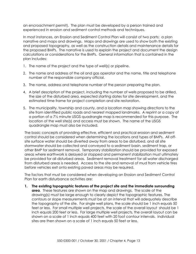
an encroachment permit). The plan must be developed by a person trained and experienced in erosion and sediment control methods and techniques.
In most instances, an Erosion and Sediment Control Plan will consist of two parts: a plan narrative and maps and drawings. Maps and drawings are used to show both the existing and proposed topography, as well as the construction details and maintenance details for the proposed BMPs. The narrative is used to explain the project and document the design calculations or considerations for the BMPs. General information that is contained in the plan includes:
1. The name of the project and the type of well(s) or pipeline.
2. The name and address of the oil and gas operator and the name, title and telephone number of the responsible company official.
3. The name, address and telephone number of the person preparing the plan.
4. A brief description of the project, including the number of wells proposed to be drilled, the size of the disturbed area, expected starting dates for site development, and the estimated time frame for project completion and site restoration.
5. The municipality, township and county, and a location map showing directions to the site from identified public roads and nearest mapped landmarks. A reprint or a copy of a portion of a 7½ minute USGS quadrangle map is recommended for this purpose. The location of the well site(s) and access must be shown. The name of the USGS quadrangle map must also be included.
The basic concepts of providing effective, efficient and practical erosion and sediment control should be considered when determining the locations and types of BMPs. All off-site surface water should be diverted away from areas to be disturbed, and all site stormwater should be collected and conveyed to a sediment basin, sediment trap, or other BMP for sediment removal. Temporary stabilization should be provided for exposed areas where earthwork is delayed or stopped and permanent stabilization must ultimately be provided for all disturbed areas. Sediment removal treatment for all water discharged from disturbed areas is needed. Access to the site and removal of mud from vehicle tires before vehicles exit onto existing paved areas may be required.
The factors that must be considered when developing an Erosion and Sediment Control Plan for earth disturbance activities are:
1. The existing topographic features of the project site and the immediate surrounding area. These features are shown on the map and drawings. The scale of the drawing(s) must be large enough to clearly depict the topographic features. The contours or slope measurements must be at an interval that will adequately describe the topography of the site. For single well plans, the scale should be 1 inch equals 50 feet or less. For small multiple well projects, the scale of the overall layout should be 1 inch equals 200 feet or less. For large multiple well projects, the overall layout can be shown on a scale of 1 inch equals 400 feet with 20 foot contour intervals. Individual sites are then shown on a scale of 1 inch equals 50 feet or less.
550-0300-001 / October 30, 2001 / Chapter 4, Page 13
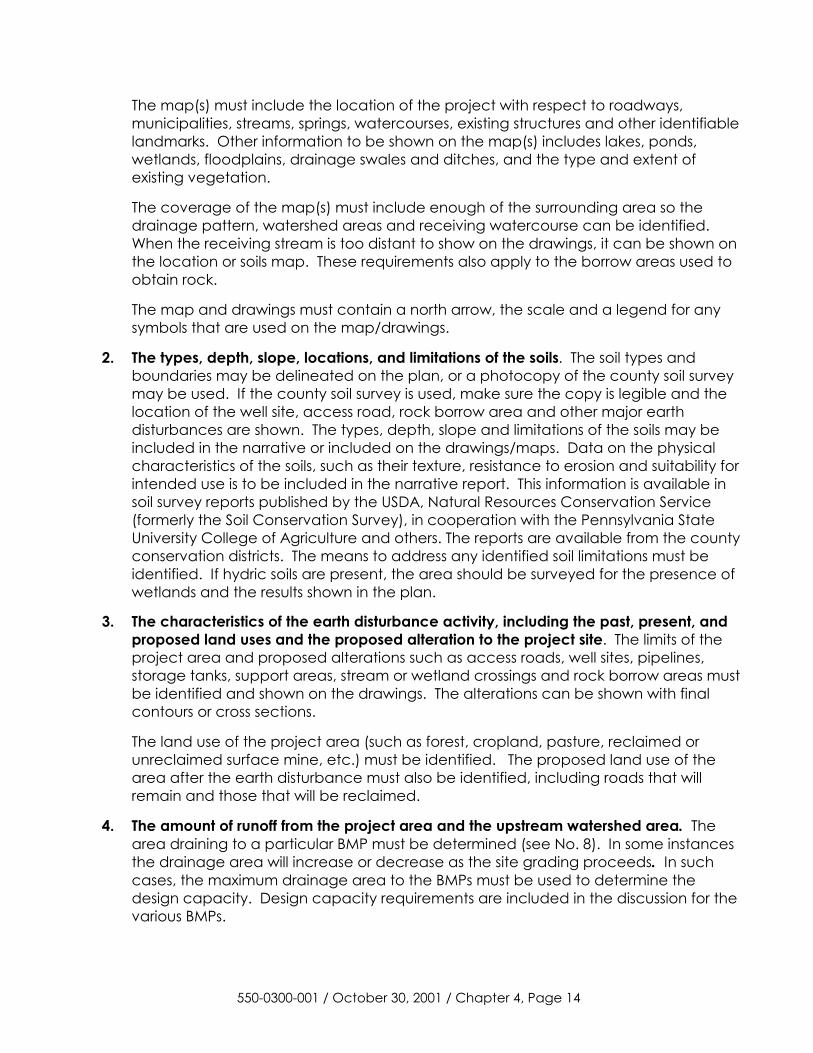
The map(s) must include the location of the project with respect to roadways, municipalities, streams, springs, watercourses, existing structures and other identifiable landmarks. Other information to be shown on the map(s) includes lakes, ponds, wetlands, floodplains, drainage swales and ditches, and the type and extent of existing vegetation.
The coverage of the map(s) must include enough of the surrounding area so the drainage pattern, watershed areas and receiving watercourse can be identified. When the receiving stream is too distant to show on the drawings, it can be shown on the location or soils map. These requirements also apply to the borrow areas used to obtain rock.
The map and drawings must contain a north arrow, the scale and a legend for any symbols that are used on the map/drawings.
2. The types, depth, slope, locations, and limitations of the soils. The soil types and boundaries may be delineated on the plan, or a photocopy of the county soil survey may be used. If the county soil survey is used, make sure the copy is legible and the location of the well site, access road, rock borrow area and other major earth disturbances are shown. The types, depth, slope and limitations of the soils may be included in the narrative or included on the drawings/maps. Data on the physical characteristics of the soils, such as their texture, resistance to erosion and suitability for intended use is to be included in the narrative report. This information is available in soil survey reports published by the USDA, Natural Resources Conservation Service (formerly the Soil Conservation Survey), in cooperation with the Pennsylvania State University College of Agriculture and others. The reports are available from the county conservation districts. The means to address any identified soil limitations must be identified. If hydric soils are present, the area should be surveyed for the presence of wetlands and the results shown in the plan.
3. The characteristics of the earth disturbance activity, including the past, present, and proposed land uses and the proposed alteration to the project site. The limits of the project area and proposed alterations such as access roads, well sites, pipelines, storage tanks, support areas, stream or wetland crossings and rock borrow areas must be identified and shown on the drawings. The alterations can be shown with final contours or cross sections.
The land use of the project area (such as forest, cropland, pasture, reclaimed or unreclaimed surface mine, etc.) must be identified. The proposed land use of the area after the earth disturbance must also be identified, including roads that will remain and those that will be reclaimed.
4. The amount of runoff from the project area and the upstream watershed area. The area draining to a particular BMP must be determined (see No. 8). In some instances the drainage area will increase or decrease as the site grading proceeds. In such cases, the maximum drainage area to the BMPs must be used to determine the design capacity. Design capacity requirements are included in the discussion for the various BMPs.
550-0300-001 / October 30, 2001 / Chapter 4, Page 14
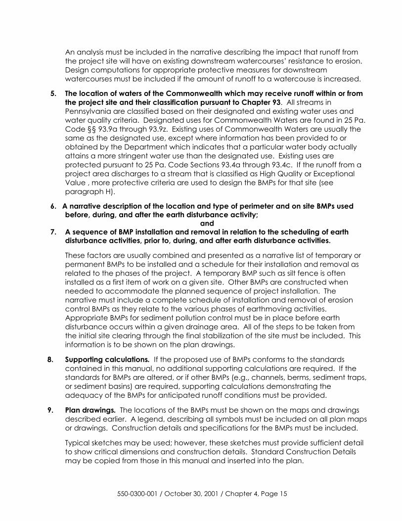
An analysis must be included in the narrative describing the impact that runoff from the project site will have on existing downstream watercourses’ resistance to erosion. Design computations for appropriate protective measures for downstream watercourses must be included if the amount of runoff to a watercouse is increased.
5. The location of waters of the Commonwealth which may receive runoff within or from the project site and their classification pursuant to Chapter 93. All streams in Pennsylvania are classified based on their designated and existing water uses and water quality criteria. Designated uses for Commonwealth Waters are found in 25 Pa. Code §§ 93.9a through 93.9z. Existing uses of Commonwealth Waters are usually the same as the designated use, except where information has been provided to or obtained by the Department which indicates that a particular water body actually attains a more stringent water use than the designated use. Existing uses are protected pursuant to 25 Pa. Code Sections 93.4a through 93.4c. If the runoff from a project area discharges to a stream that is classified as High Quality or Exceptional Value , more protective criteria are used to design the BMPs for that site (see paragraph H).
6. A narrative description of the location and type of perimeter and on site BMPs used before, during, and after the earth disturbance activity;
and 7. A sequence of BMP installation and removal in relation to the scheduling of earth
disturbance activities, prior to, during, and after earth disturbance activities.
These factors are usually combined and presented as a narrative list of temporary or permanent BMPs to be installed and a schedule for their installation and removal as related to the phases of the project. A temporary BMP such as silt fence is often installed as a first item of work on a given site. Other BMPs are constructed when needed to accommodate the planned sequence of project installation. The narrative must include a complete schedule of installation and removal of erosion control BMPs as they relate to the various phases of earthmoving activities. Appropriate BMPs for sediment pollution control must be in place before earth disturbance occurs within a given drainage area. All of the steps to be taken from the initial site clearing through the final stabilization of the site must be included. This information is to be shown on the plan drawings.
8. Supporting calculations. If the proposed use of BMPs conforms to the standards contained in this manual, no additional supporting calculations are required. If the standards for BMPs are altered, or if other BMPs (e.g., channels, berms, sediment traps, or sediment basins) are required, supporting calculations demonstrating the adequacy of the BMPs for anticipated runoff conditions must be provided.
9. Plan drawings. The locations of the BMPs must be shown on the maps and drawings described earlier. A legend, describing all symbols must be included on all plan maps or drawings. Construction details and specifications for the BMPs must be included.
Typical sketches may be used; however, these sketches must provide sufficient detail to show critical dimensions and construction details. Standard Construction Details may be copied from those in this manual and inserted into the plan.
550-0300-001 / October 30, 2001 / Chapter 4, Page 15
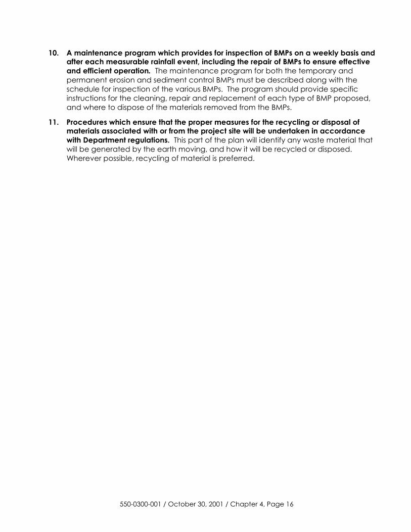
10. A maintenance program which provides for inspection of BMPs on a weekly basis and after each measurable rainfall event, including the repair of BMPs to ensure effective and efficient operation. The maintenance program for both the temporary and permanent erosion and sediment control BMPs must be described along with the schedule for inspection of the various BMPs. The program should provide specific instructions for the cleaning, repair and replacement of each type of BMP proposed, and where to dispose of the materials removed from the BMPs.
11. Procedures which ensure that the proper measures for the recycling or disposal of materials associated with or from the project site will be undertaken in accordance with Department regulations. This part of the plan will identify any waste material that will be generated by the earth moving, and how it will be recycled or disposed. Wherever possible, recycling of material is preferred.
550-0300-001 / October 30, 2001 / Chapter 4, Page 16
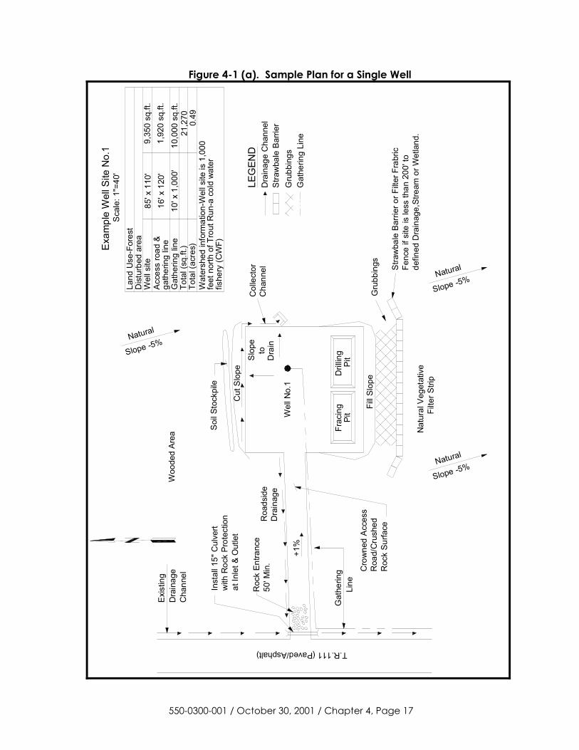
Figure 4-1 (a). Sample Plan for a Single Well
550-0300-001 / October 30, 2001 / Chapter 4, Page 17
Col
lect
orC
hann
el
Exis
ting
Dra
inag
e
Line
Gat
herin
g
Cut
Slo
pe
Soi
l Sto
ckpi
le
Pit
Dril
ling
Frac
ing
Pit
Fill
Slop
e
Wel
l No.
1
Dra
into
Slo
pe
at In
let &
Out
let
with
Roc
k Pr
otec
tion
Inst
all 1
5" C
ulve
rt
+1%
Woo
ded
Area
T.R.111 (Paved/Asphalt)
LEG
END
Dra
inag
e C
hann
elS
traw
bale
Bar
rier
Gru
bbin
gsG
athe
ring
Line
Sca
le: 1
"=40
'Ex
ampl
e W
ell S
ite N
o.1
Wat
ersh
ed in
form
atio
n-W
ell s
ite is
1,0
00
fishe
ry (C
WF)
feet
nor
th o
f Tro
ut R
un-a
col
d w
ater
Land
Use
-For
est
Dis
turb
ed a
rea
Wel
l site
Acc
ess
road
&ga
ther
ing
line
Gat
herin
g lin
eTo
tal (
sq.ft
.)To
tal (
acre
s)
85' x
110
'9,
350
sq.ft
.
10' x
1,0
00'
10,0
00 s
q.ft.
21,2
700.
49
16' x
120
'1,
920
sq.ft
.
Gru
bbin
gs
Natural
Slope -5%
Nat
ural
Veg
etat
ive
Filte
r Stri
p
Slope -5%Natural
Natural
Slope -5%
Roa
dsid
eD
rain
age
Cro
wne
d A
cces
sR
oad/
Cru
shed
Roc
k Su
rface
Stra
wba
le B
arrie
r or F
ilter
Fra
bric
Fenc
e if
site
is le
ss th
an 2
00' t
ode
fined
Dra
inag
e,St
ream
or W
etla
nd.
Cha
nnel
50' M
in.
Roc
k En
tranc
e
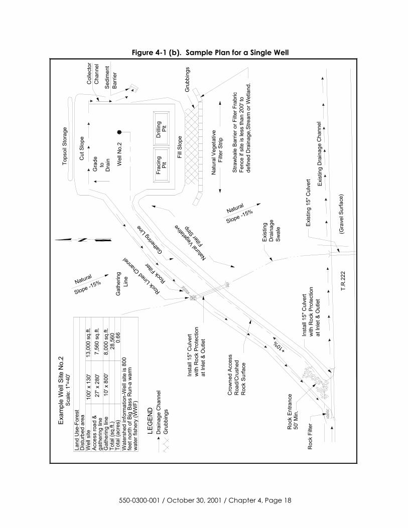
Figure 4-1 (b). Sample Plan for a Single Well
7,56
0 sq
.ft.
27' x
280
'
0.66
28,5
608,
000
sq.ft
.10
' x 8
00'
13,0
00 s
q.ft.
100'
x 1
30'
Tota
l (ac
res)
Tota
l (sq
.ft.)
Gat
herin
g lin
ega
ther
ing
line
Acce
ss ro
ad &
Wel
l site
Dis
turb
ed a
rea
Land
Use
-For
est
feet
nor
th o
f Big
Bas
s R
un-a
war
mw
ater
fish
ery
(WW
F)
Wat
ersh
ed in
form
atio
n-W
ell s
ite is
800
Exam
ple
Wel
l Site
No.
2S
cale
: 1"=
40'
Gru
bbin
gsD
rain
age
Cha
nnel
LEG
END
Slope -15%Natural
Slope -15%Natural
Pit
Dril
ling
Frac
ing
Pit
at In
let &
Out
let
with
Roc
k Pr
otec
tion
Inst
all 1
5" C
ulve
rtEx
istin
g 15
" Cul
vert
at In
let &
Out
let
with
Roc
k Pr
otec
tion
Inst
all 1
5" C
ulve
rt
Exis
ting
Dra
inag
e C
hann
el
T.R
.222
(Gra
vel S
urfa
ce)
Roc
k Fi
lter
Cro
wne
d Ac
cess
Roa
d/C
rush
edR
ock
Surfa
ce
+10%
Swal
eD
rain
age
Exis
ting
Rock F
ilter
Rock L
ined C
hann
el
Nat
ural
Veg
etat
ive
Filte
r Stri
p
Natural
Veg
etativ
e
Filter
Strip
Fill
Slop
e
Sedi
men
t
Cut
Slo
pe
Wel
l No.
2
Dra
into
Gra
deTops
oil S
tora
ge
Gru
bbin
gs
Bar
rier
Stra
wba
le B
arrie
r or F
ilter
Fra
bric
Fenc
e if
site
is le
ss th
an 2
00' t
ode
fined
Dra
inag
e,St
ream
or W
etla
nd.
Line
Gat
herin
g
Gatheri
ng Li
ne
Col
lect
orC
hann
el
Roc
k En
tranc
e50
' Min
.
550-0300-001 / October 30, 2001 / Chapter 4, Page 18
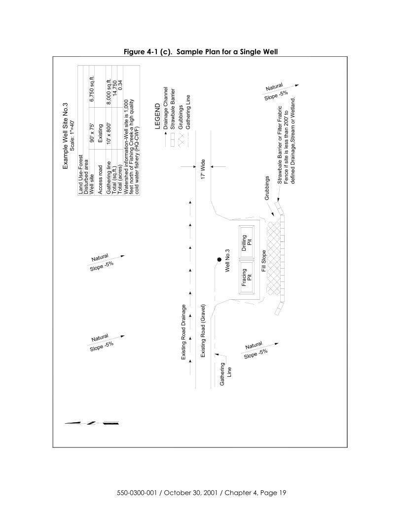
Figure 4-1 (c). Sample Plan for a Single Well
Pit
Dril
ling
Frac
ing
Pit
LEG
END
Dra
inag
e C
hann
elS
traw
bale
Bar
rier
Gru
bbin
gsG
athe
ring
Line
Sca
le: 1
"=40
'E
xam
ple
Wel
l Site
No.
3
Wat
ersh
ed in
form
atio
n-W
ell s
ite is
1,0
00
cold
wat
er fi
sher
y (H
Q-C
WF)
feet
nor
th o
f Fis
hing
Cre
ek-a
hig
h qu
ality
Land
Use
-For
est
Dis
turb
ed a
rea
Wel
l site
Acc
ess
road
Gat
herin
g lin
eTo
tal (
sq.ft
.)To
tal (
acre
s)
90' x
75'
6,75
0 sq
.ft.
10' x
800
'8,
000
sq.ft
.14
,750
0.34
Exi
stin
g
Slope -5%Natural
Stra
wba
le B
arrie
r or F
ilter F
rabr
icFe
nce
if si
te is
less
than
200
' to
defin
ed D
rain
age,
Stre
am o
r Wet
land
.
Fill
Slop
eG
rubb
ings
Wel
l No.
3
Exi
stin
g R
oad
(Gra
vel)
Exi
stin
g R
oad
Dra
inag
e
Slope -5%Natural
Slope -5%Natural
Slope -5%Natural
Line
Gat
herin
g
17' W
ide
550-0300-001 / October 30, 2001 / Chapter 4, Page 19
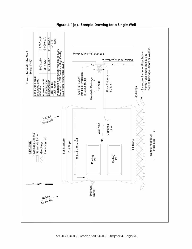
Figure 4-1(d). Sample Drawing for a Single Well
550-0300-001 / October 30, 2001 / Chapter 4, Page 20
LEG
END
Dra
inag
e C
hann
elS
traw
bale
Bar
rier
Gru
bbin
gsG
athe
ring
Line
Sca
le: 1
"=50
'E
xam
ple
Wel
l Site
No.
4
Wat
ersh
ed in
form
atio
n-W
ell s
ite is
1,0
00
cold
wat
er fi
sher
y (H
Q-C
WF)
feet
nor
th o
f Mill
Cre
ek -
a H
igh
Qua
lity
Land
Use
-For
est
Dis
turb
ed a
rea
Wel
l site
Gat
herin
g lin
eTo
tal (
sq.ft
.)To
tal (
acre
s)
200'
x 2
10'
42,0
00 s
q.ft.
12' x
1,2
00'
14,4
00 s
q.ft.
55,4
001.
36
17' W
ide
Pit
Dril
ling
Frac
ing
Pit
3,00
0 sq
.ft.
25' x
120
'ga
ther
ing
line
Acce
ss ro
ad &
Roa
dsid
e D
rain
age
Existing Drainage Channel
T.R. 666 (Asphalt Surface)
Wel
l No.
4
at In
let &
Out
let
with
Roc
k Pr
otec
tion
Inst
all 1
5" C
ulve
rt
Slope -5%Natural
Stra
wba
le B
arrie
r or F
ilter F
rabr
icFe
nce
if si
te is
less
than
200
' to
defin
ed D
rain
age,
Stre
am o
r Wet
land
.
Gru
bbin
gs
Soi
l Sto
ckpi
le
Col
lect
or C
hann
el
Line
Gat
herin
g50
' Min
.R
ock
Entra
nce
Fill
Slop
e
Cut
Slo
pe
Sed
imen
tB
arrie
r
Filte
r Stri
p
Slope -5%Natural
Nat
ural
Veg
etat
ive
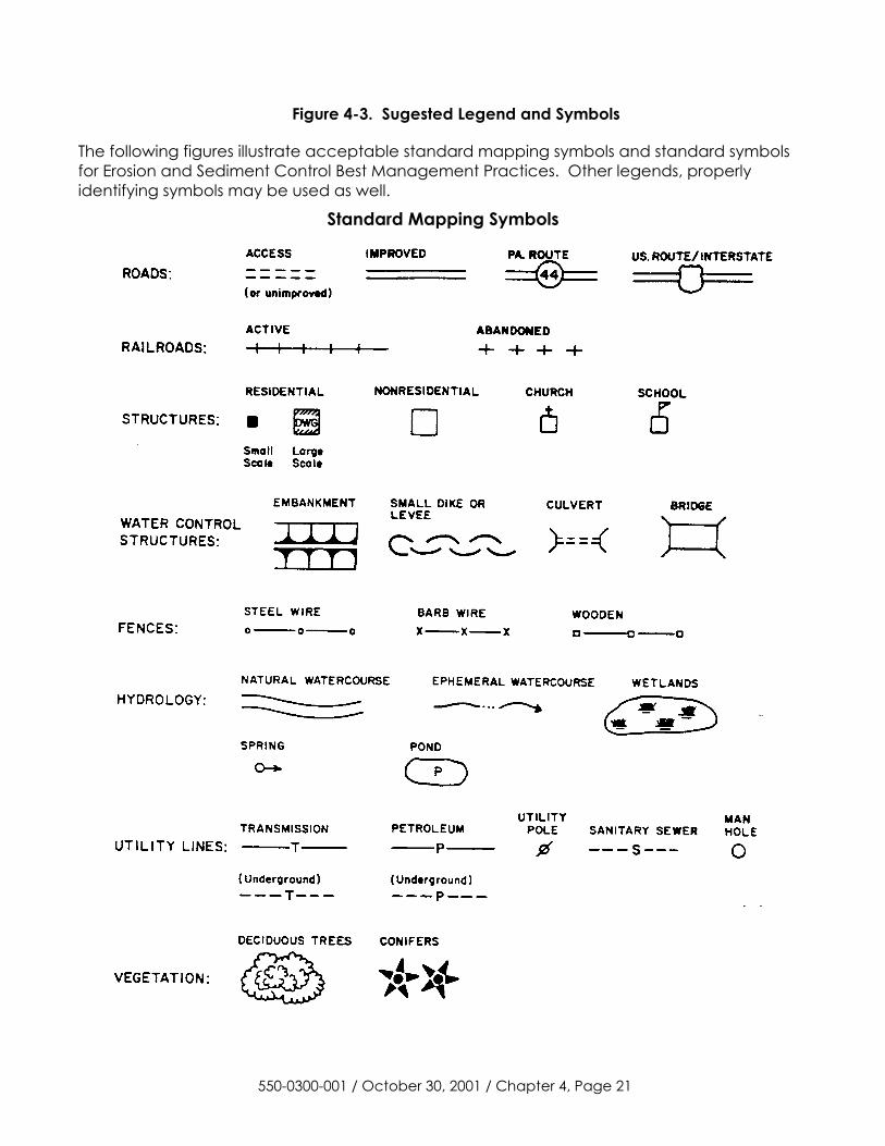
Figure 4-3. Sugested Legend and Symbols The following figures illustrate acceptable standard mapping symbols and standard symbols for Erosion and Sediment Control Best Management Practices. Other legends, properly identifying symbols may be used as well.
Standard Mapping Symbols
550-0300-001 / October 30, 2001 / Chapter 4, Page 21
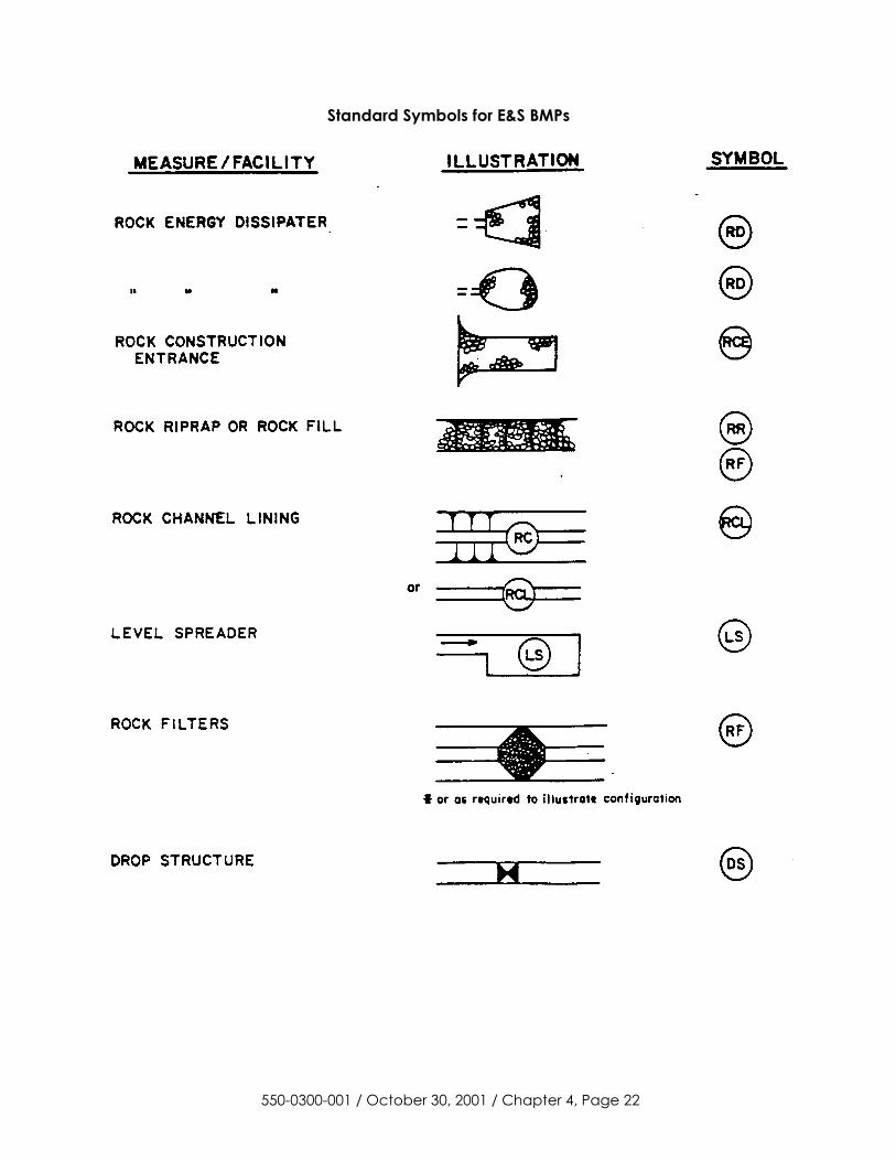
Standard Symbols for E&S BMPs
550-0300-001 / October 30, 2001 / Chapter 4, Page 22
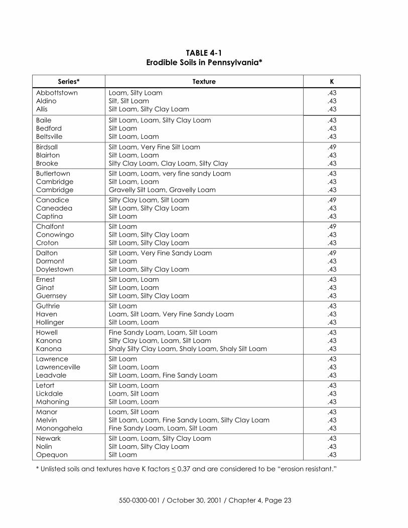
TABLE 4-1 Erodible Soils in Pennsylvania*
Series* Texture K
Abbottstown Aldino Allis
Loam, Silty Loam Silt, Silt Loam Silt Loam, Silty Clay Loam
.43
.43
.43 Baile Bedford Beltsville
Silt Loam, Loam, Silty Clay Loam Silt Loam Silt Loam, Loam
.43
.43
.43 Birdsall Blairton Brooke
Silt Loam, Very Fine Silt Loam Silt Loam, Loam Silty Clay Loam, Clay Loam, Silty Clay
.49
.43
.43 Butlertown Cambridge Cambridge
Silt Loam, Loam, very fine sandy Loam Silt Loam, Loam Gravelly Silt Loam, Gravelly Loam
.43
.43
.43 Canadice Caneadea Captina
Silty Clay Loam, Silt Loam Silt Loam, Silty Clay Loam Silt Loam
.49
.43
.43 Chalfont Conowingo Croton
Silt Loam Silt Loam, Silty Clay Loam Silt Loam, Silty Clay Loam
.49
.43
.43 Dalton Dormont Doylestown
Silt Loam, Very Fine Sandy Loam Silt Loam Silt Loam, Silty Clay Loam
.49
.43
.43 Ernest Ginat Guernsey
Silt Loam, Loam Silt Loam, Loam Silt Loam, Silty Clay Loam
.43
.43
.43 Guthrie Haven Hollinger
Silt Loam Loam, Silt Loam, Very Fine Sandy Loam Silt Loam, Loam
.43
.43
.43 Howell Kanona Kanona
Fine Sandy Loam, Loam, Silt Loam Silty Clay Loam, Loam, Silt Loam Shaly Silty Clay Loam, Shaly Loam, Shaly Silt Loam
.43
.43
.43 Lawrence Lawrenceville Leadvale
Silt Loam Silt Loam, Loam Silt Loam, Loam, Fine Sandy Loam
.43
.43
.43 Letort Lickdale Mahoning
Silt Loam, Loam Loam, Silt Loam Silt Loam, Loam
.43
.43
.43 Manor Melvin Monongahela
Loam, Silt Loam Silt Loam, Loam, Fine Sandy Loam, Silty Clay Loam Fine Sandy Loam, Loam, Silt Loam
.43
.43
.43 Newark Nolin Opequon
Silt Loam, Loam, Silty Clay Loam Silt Loam, Silty Clay Loam Silt Loam
.43
.43
.43
* Unlisted soils and textures have K factors < 0.37 and are considered to be “erosion resistant.”
550-0300-001 / October 30, 2001 / Chapter 4, Page 23
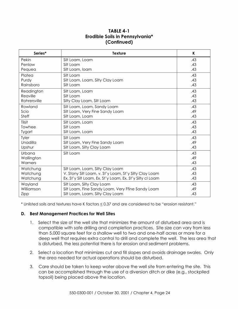
TABLE 4-1 Erodible Soils in Pennsylvania*
(Continued)
Series* Texture K Pekin Penlaw Pequea
Silt Loam, Loam Silt Loam Silt Loam, loam
.43
.43
.43 Platea Purdy Rainsboro
Silt Loam Silt Loam, Loam, Silty Clay Loam Silt Loam
.43
.43
.43 Readington Reaville Rohrersville
Silt Loam, Loam Silt Loam Silty Clay Loam, Silt Loam
.43
.43
.43 Rowland Scio Steff
Silt Loam, Loam, Sandy Loam Silt Loam, Very Fine Sandy Loam Silt Loam, Loam
.43
.49
.43 Tilsit Towhee Tygart
Silt Loam, Loam Silt Loam Silt Loam, Loam
.43
.43
.43 Tyler Unadilla Upshur
Silt Loam Silt Loam, Very Fine Sandy Loam Silt Loam, Silty Clay Loam
.43
.49
.43 Urbana Wallington Warners
Silt Loam .43 .49 .43
Watchung Watchung Watchung
Silt Loam, Loam, Silty Clay Loam V. Stony Silt Loam, v. St’y Loam, St’y Silty Clay Loam Ex. St’y Silt Loam, Ex. St’y Loam, Ex. St’y Silty cl Loam
.43
.43
.43 Wayland Williamson Zipp
Silt Loam, Silty Clay Loam Silt Loam, Fine Sandy Loam, Very Ffine Sandy Loam Silt Loam, Loam, Silty Clay Loam
.43
.49
.43 * Unlisted soils and textures have K factors < 0.37 and are considered to be “erosion resistant.” D. Best Management Practices for Well Sites
1. Select the size of the well site that minimizes the amount of disturbed area and is compatible with safe drilling and completion practices. Site size can vary from less than 5,000 square feet for a shallow well to two and one-half acres or more for a deep well that requires extra control to drill and complete the well. The less area that is disturbed, the less potential there is for erosion and sediment problems.
2. Select a location that minimizes cut and fill slopes and avoids drainage swales. Only the area needed for actual operations should be disturbed.
3. Care should be taken to keep water above the well site from entering the site. This can be accomplished through the use of a diversion ditch or dike (e.g., stockpiled topsoil) being placed above the location.
550-0300-001 / October 30, 2001 / Chapter 4, Page 24
4. Runoff from the pad and out slopes of the pad should be collected in a channel and diverted to a sediment trap, sediment basin or other control facility. These BMPs must be designed in accordance with the size of the disturbed area and with controlled outlets to insure proper outflow velocities. All sediment carrying surface water from a well site must be passed through a sediment trapping facility.
5. Cut and fill slopes and other disturbed areas that will remain after the well is completed should be seeded and mulched.
6. Restoration of the well site and access road should be accomplished as soon as possible after completion of the well. All pits must be properly closed and the site regraded to compliment the surrounding contours except for the well maintenance pad and access road. All disturbed areas along the access corridor, well site and pipelines must be stabilized with appropriate BMPs.
7. Maintenance - Suitable temporary erosion control measures must be used during construction until permanent controls can be established. BMPs must be properly maintained throughout the life of the entire operation. The maintenance program must provide for inspection of BMPs on a weekly basis and after each measurable rainfall event, including the repair of the BMPs to ensure effective and efficient operation.
8. Restoration - After the well is plugged, the site and access road should be closed and restored as follows:
a. Remove all equipment from the site, restore the natural drainage patterns and remove sedimentation ponds, or other control facilities.
b. Round or shape all disturbed areas to conform the site to adjacent terrain.
c. All unstabilized areas should be scarified, limed, fertilized, seeded and mulched.
9. Diversion Channels and Collector Channels - Diversion channels must be provided to collect runoff from upslope areas and divert the water around the well site. This diversion can be constructed by excavating a channel upslope of the well site, or by stockpiling the topsoil above the well site to form a berm to divert the runoff. The diversion should outlet to a level spreader or a vegetative filter strip. Another option is to install a channel at the base of the cut slope to collect the runoff before it runs onto the pad and into the drilling and fracing pits. This channel is also beneficial when springs or seeps are encountered in the cut slope. This channel should be stabilized and outlet to a level spreader or vegetative filter strip, a sediment trap or sedimentation basin.
550-0300-001 / October 30, 2001 / Chapter 4, Page 25
2 MAX 2 MAX
EROSION RESISTANT LINING
2 MAX 2 MAX
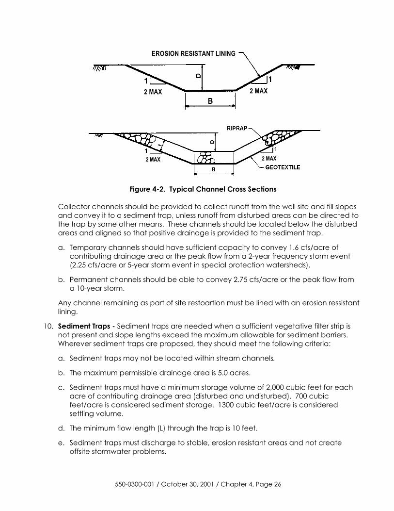
Figure 4-2. Typical Channel Cross Sections
Collector channels should be provided to collect runoff from the well site and fill slopes and convey it to a sediment trap, unless runoff from disturbed areas can be directed to the trap by some other means. These channels should be located below the disturbed areas and aligned so that positive drainage is provided to the sediment trap.
a. Temporary channels should have sufficient capacity to convey 1.6 cfs/acre of contributing drainage area or the peak flow from a 2-year frequency storm event (2.25 cfs/acre or 5-year storm event in special protection watersheds).
b. Permanent channels should be able to convey 2.75 cfs/acre or the peak flow from a 10-year storm.
Any channel remaining as part of site restoartion must be lined with an erosion ressistant lining.
10. Sediment Traps - Sediment traps are needed when a sufficient vegetative filter strip is not present and slope lengths exceed the maximum allowable for sediment barriers. Wherever sediment traps are proposed, they should meet the following criteria:
a. Sediment traps may not be located within stream channels.
b. The maximum permissible drainage area is 5.0 acres.
c. Sediment traps must have a minimum storage volume of 2,000 cubic feet for each acre of contributing drainage area (disturbed and undisturbed). 700 cubic feet/acre is considered sediment storage. 1300 cubic feet/acre is considered settling volume.
d. The minimum flow length (L) through the trap is 10 feet.
e. Sediment traps must discharge to stable, erosion resistant areas and not create offsite stormwater problems.
550-0300-001 / October 30, 2001 / Chapter 4, Page 26
f. The minimum trap storage depth is 2.0 feet (1 foot for sediment storage and 1 foot dewatering zone).
g. Traps must be able to dewater the settling volume completely.
h. The maximum constructed embankment height is 5.0 feet.
i. Maximum embankment side slope = 2:1 (H:V)
j. Minimum freeboard above the maximum design water level is 12”.
k. Embankment spillways criteria:
(1) The width of the spillway (in feet) shall be at least 2 times the number of acres contributing to the drainage area, or 2 times the height of the spillway crest, whichever is greater. Wherever traps discharge directly to a wetland, the spillway width should be at least 4 times the number of tributary acres.
(2) The minimum spillway crest elevation is the elevation at which the required 2,000 cubic feet per contributing drainage acre storage capacity is provided.
(3) Maximum spillway side slope = 2:1 (H:V)
(4) Minimum rock size construction of the spillway is R-3. Note: The entire spillway should be constructed with rock (see Figure 27).
(5) The inside face of the spillway should be covered with a 6” (minimum) thick layer of filter stone (maximum size = AASHTO #57).
(6) Filter fabric should be securely staked on top of the filter stone up to the Sediment Storage Elevation. Any excess fabric should be staked to the bottom of the trap.
550-0300-001 / October 30, 2001 / Chapter 4, Page 27
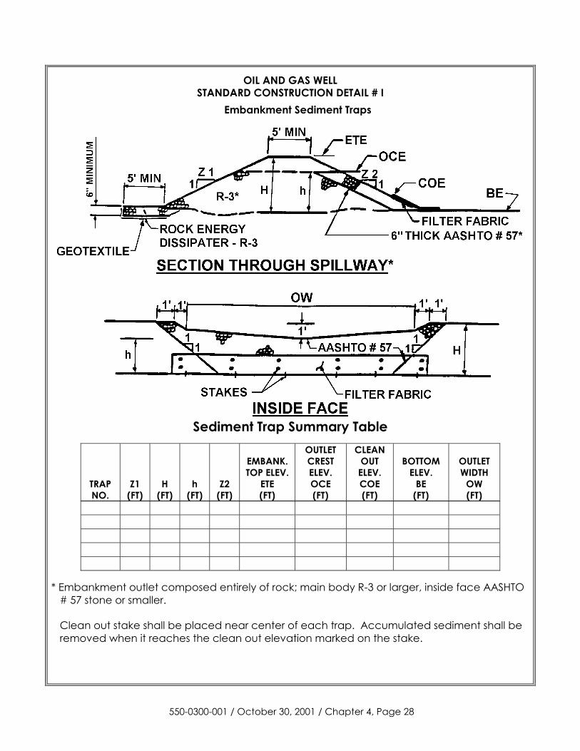
OIL AND GAS WELL STANDARD CONSTRUCTION DETAIL # I
Embankment Sediment Traps
Sediment Trap Summary Table
TRAP NO.
Z1 (FT)
H
(FT)
h
(FT)
Z2
(FT)
EMBANK. TOP ELEV.
ETE (FT)
OUTLET CREST ELEV. OCE (FT)
CLEAN OUT ELEV. COE (FT)
BOTTOM
ELEV. BE
(FT)
OUTLET WIDTH
OW (FT)
* Embankment outlet composed entirely of rock; main body R-3 or larger, inside face AASHTO
# 57 stone or smaller.
Clean out stake shall be placed near center of each trap. Accumulated sediment shall be removed when it reaches the clean out elevation marked on the stake.
550-0300-001 / October 30, 2001 / Chapter 4, Page 28
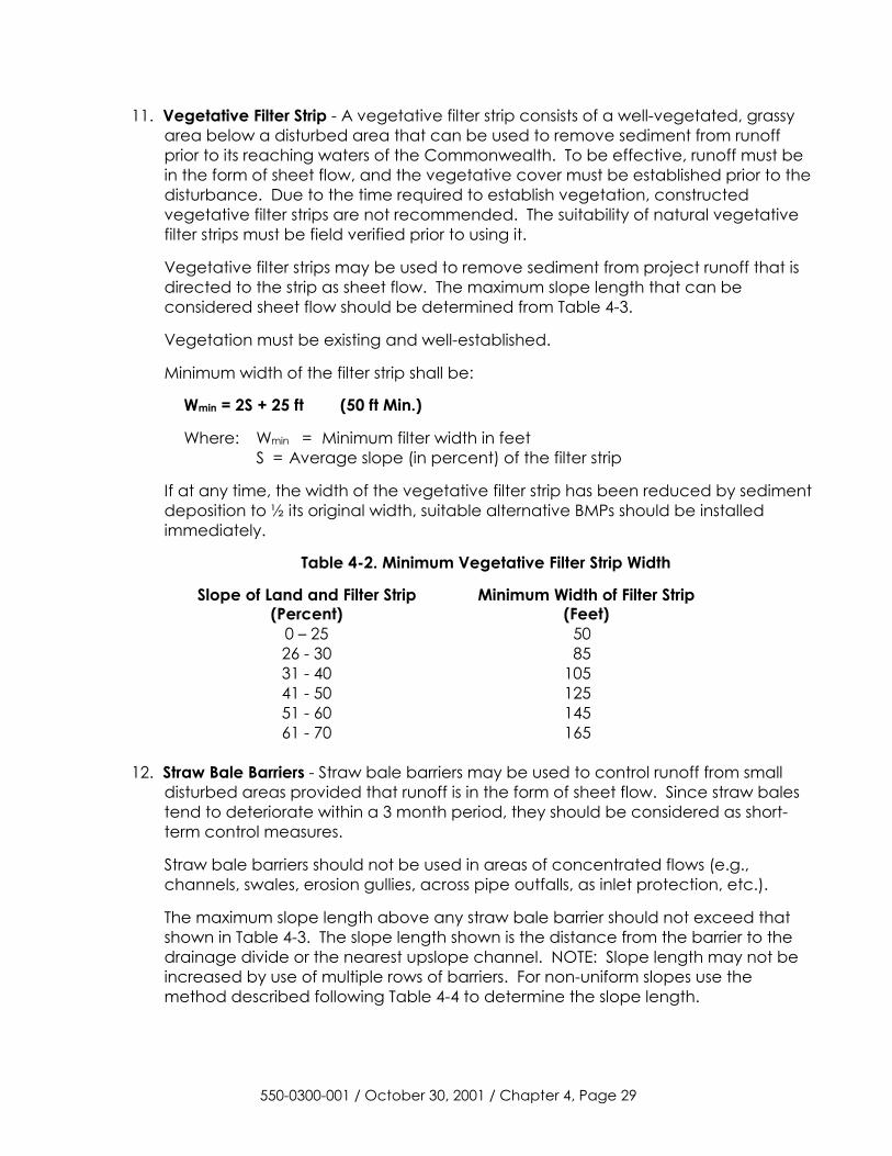
11. Vegetative Filter Strip - A vegetative filter strip consists of a well-vegetated, grassy area below a disturbed area that can be used to remove sediment from runoff prior to its reaching waters of the Commonwealth. To be effective, runoff must be in the form of sheet flow, and the vegetative cover must be established prior to the disturbance. Due to the time required to establish vegetation, constructed vegetative filter strips are not recommended. The suitability of natural vegetative filter strips must be field verified prior to using it.
Vegetative filter strips may be used to remove sediment from project runoff that is directed to the strip as sheet flow. The maximum slope length that can be considered sheet flow should be determined from Table 4-3.
Vegetation must be existing and well-established.
Minimum width of the filter strip shall be:
Wmin = 2S + 25 ft (50 ft Min.)
Where: Wmin = Minimum filter width in feet S = Average slope (in percent) of the filter strip
If at any time, the width of the vegetative filter strip has been reduced by sediment deposition to ½ its original width, suitable alternative BMPs should be installed immediately.
Table 4-2. Minimum Vegetative Filter Strip Width
Slope of Land and Filter Strip (Percent)
Minimum Width of Filter Strip (Feet)
0 – 25 50 26 - 30 85 31 - 40 105 41 - 50 125 51 - 60 145 61 - 70 165
12. Straw Bale Barriers - Straw bale barriers may be used to control runoff from small
disturbed areas provided that runoff is in the form of sheet flow. Since straw bales tend to deteriorate within a 3 month period, they should be considered as short-term control measures.
Straw bale barriers should not be used in areas of concentrated flows (e.g., channels, swales, erosion gullies, across pipe outfalls, as inlet protection, etc.).
The maximum slope length above any straw bale barrier should not exceed that shown in Table 4-3. The slope length shown is the distance from the barrier to the drainage divide or the nearest upslope channel. NOTE: Slope length may not be increased by use of multiple rows of barriers. For non-uniform slopes use the method described following Table 4-4 to determine the slope length.
550-0300-001 / October 30, 2001 / Chapter 4, Page 29
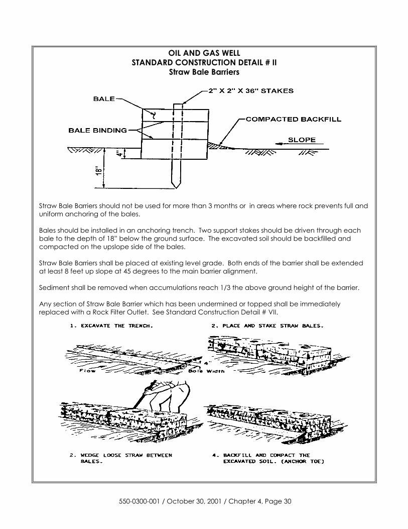
OIL AND GAS WELL STANDARD CONSTRUCTION DETAIL # II
Straw Bale Barriers
Straw Bale Barriers should not be used for more than 3 months or in areas where rock prevents full and uniform anchoring of the bales. Bales should be installed in an anchoring trench. Two support stakes should be driven through each bale to the depth of 18” below the ground surface. The excavated soil should be backfilled and compacted on the upslope side of the bales. Straw Bale Barriers shall be placed at existing level grade. Both ends of the barrier shall be extended at least 8 feet up slope at 45 degrees to the main barrier alignment. Sediment shall be removed when accumulations reach 1/3 the above ground height of the barrier. Any section of Straw Bale Barrier which has been undermined or topped shall be immediately replaced with a Rock Filter Outlet. See Standard Construction Detail # VII.
550-0300-001 / October 30, 2001 / Chapter 4, Page 30
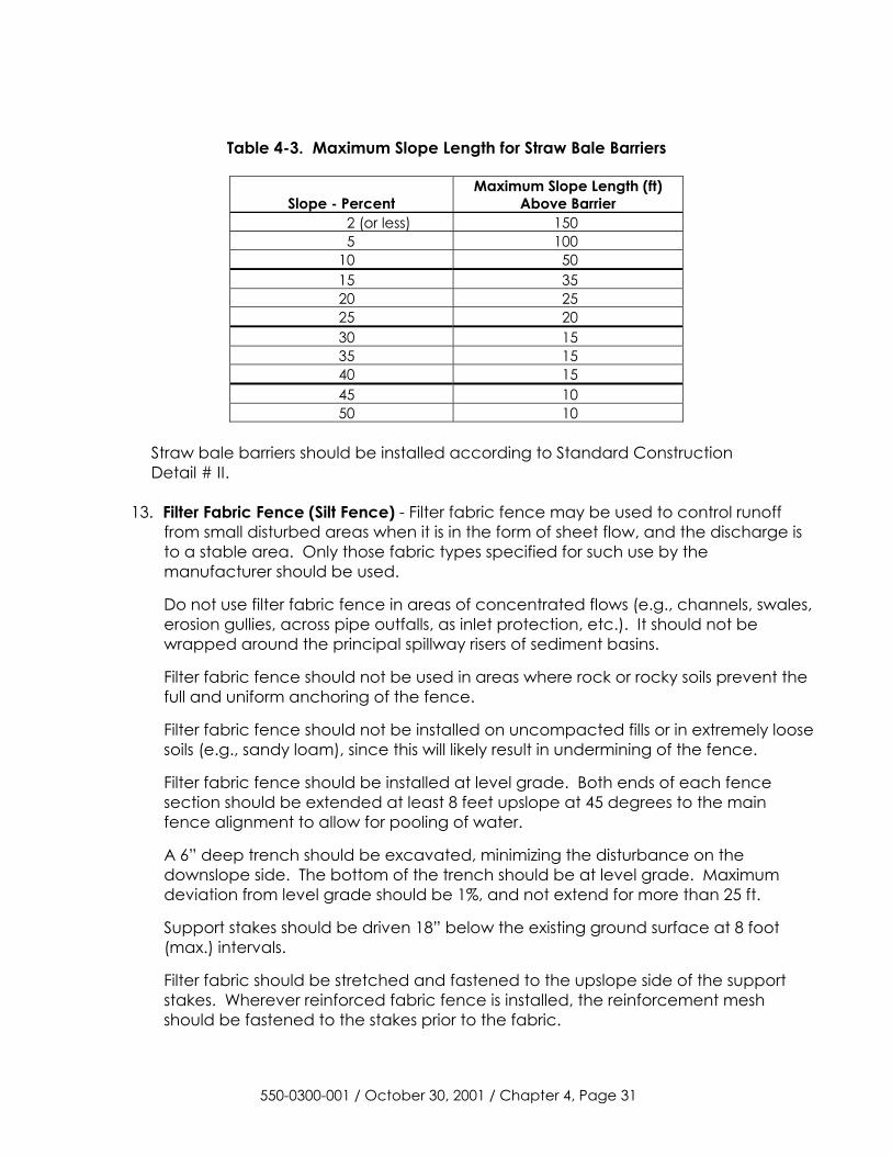
Table 4-3. Maximum Slope Length for Straw Bale Barriers
Slope - Percent Maximum Slope Length (ft)
Above Barrier 2 (or less) 150 5 100
10 50 15 35 20 25 25 20 30 15 35 15 40 15 45 10 50 10
Straw bale barriers should be installed according to Standard Construction Detail # II.
13. Filter Fabric Fence (Silt Fence) - Filter fabric fence may be used to control runoff from small disturbed areas when it is in the form of sheet flow, and the discharge is to a stable area. Only those fabric types specified for such use by the manufacturer should be used.
Do not use filter fabric fence in areas of concentrated flows (e.g., channels, swales, erosion gullies, across pipe outfalls, as inlet protection, etc.). It should not be wrapped around the principal spillway risers of sediment basins.
Filter fabric fence should not be used in areas where rock or rocky soils prevent the full and uniform anchoring of the fence.
Filter fabric fence should not be installed on uncompacted fills or in extremely loose soils (e.g., sandy loam), since this will likely result in undermining of the fence.
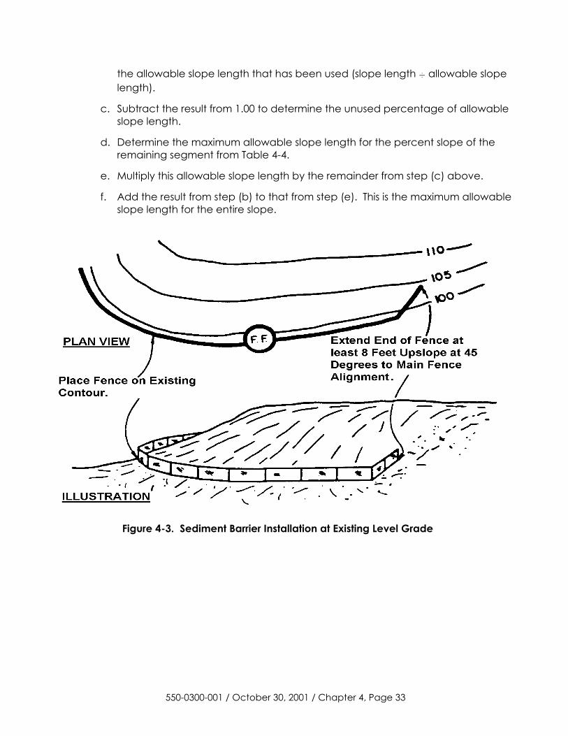
Filter fabric fence should be installed at level grade. Both ends of each fence section should be extended at least 8 feet upslope at 45 degrees to the main fence alignment to allow for pooling of water.
A 6” deep trench should be excavated, minimizing the disturbance on the downslope side. The bottom of the trench should be at level grade. Maximum deviation from level grade should be 1%, and not extend for more than 25 ft.
Support stakes should be driven 18” below the existing ground surface at 8 foot (max.) intervals.
Filter fabric should be stretched and fastened to the upslope side of the support stakes. Wherever reinforced fabric fence is installed, the reinforcement mesh should be fastened to the stakes prior to the fabric.
550-0300-001 / October 30, 2001 / Chapter 4, Page 31
At fabric ends, both ends should be wrapped around the support stake and stapled. If the fabric comes already attached to the stakes, the end stakes should be held together while the fabric is wrapped around the stakes at least one revolution prior to driving the stakes.
The bottom of the fence should be anchored by placing the fabric in the bottom of the trench, and backfilling and compacting the fill material in the trench.
Guy wires should be attached to reinforced fabric fence (see Standard Construction Detail #20). An acceptable alternative is to stake straw bales on the downslope side of the fence (see Standard Construction Detail #II).
Filter fabric fence should be inspected weekly and after each runoff event. Needed repairs should be initiated immediately after the inspection.
Straw bales generally need to be replaced every three months.
Filter fabric fence alignment should be at least 8’ from the toe of fill slopes.
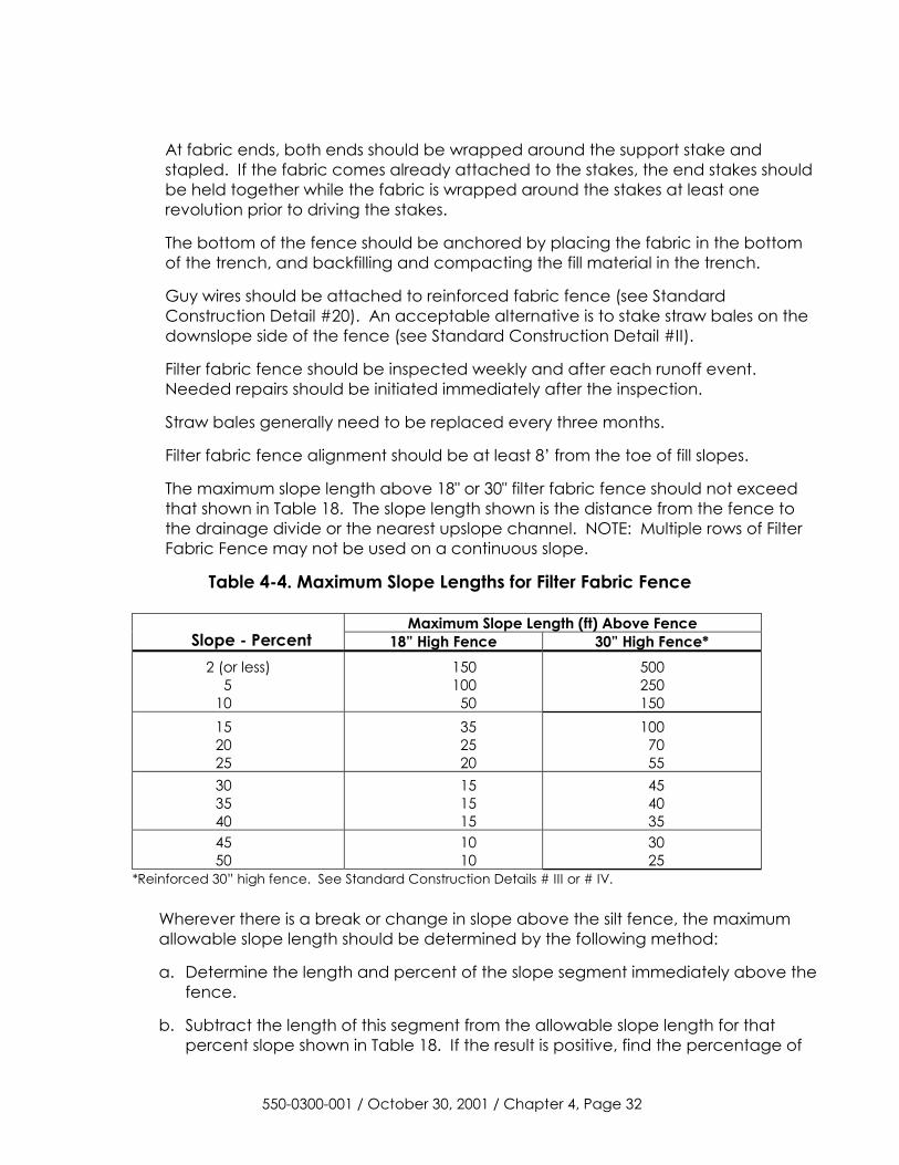
The maximum slope length above 18" or 30" filter fabric fence should not exceed that shown in Table 18. The slope length shown is the distance from the fence to the drainage divide or the nearest upslope channel. NOTE: Multiple rows of Filter Fabric Fence may not be used on a continuous slope.
Table 4-4. Maximum Slope Lengths for Filter Fabric Fence
Maximum Slope Length (ft) Above Fence Slope - Percent 18” High Fence 30” High Fence*
2 (or less) 5 10
150 100 50
500 250 150
15 20 25
35 25 20
100 70 55
30 35 40
15 15 15
45 40 35
45 50
10 10
30 25
*Reinforced 30” high fence. See Standard Construction Details # III or # IV.
Wherever there is a break or change in slope above the silt fence, the maximum allowable slope length should be determined by the following method:
a. Determine the length and percent of the slope segment immediately above the fence.
b. Subtract the length of this segment from the allowable slope length for that percent slope shown in Table 18. If the result is positive, find the percentage of
550-0300-001 / October 30, 2001 / Chapter 4, Page 32
the allowable slope length that has been used (slope length ÷ allowable slope length).
c. Subtract the result from 1.00 to determine the unused percentage of allowable slope length.
d. Determine the maximum allowable slope length for the percent slope of the remaining segment from Table 4-4.
e. Multiply this allowable slope length by the remainder from step (c) above.
f. Add the result from step (b) to that from step (e). This is the maximum allowable slope length for the entire slope.
Figure 4-3. Sediment Barrier Installation at Existing Level Grade
550-0300-001 / October 30, 2001 / Chapter 4, Page 33
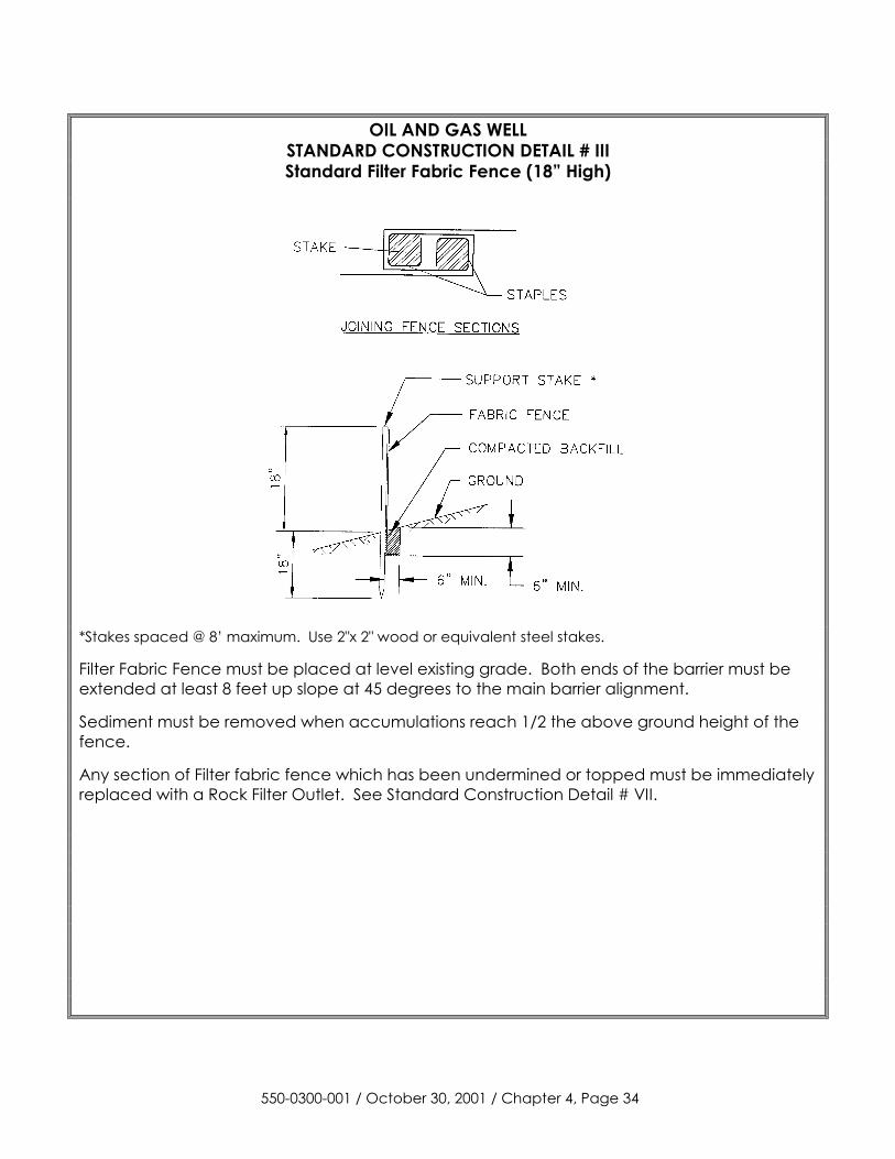
OIL AND GAS WELL STANDARD CONSTRUCTION DETAIL # III Standard Filter Fabric Fence (18” High)
*Stakes spaced @ 8’ maximum. Use 2"x 2" wood or equivalent steel stakes.
Filter Fabric Fence must be placed at level existing grade. Both ends of the barrier must be extended at least 8 feet up slope at 45 degrees to the main barrier alignment.
Sediment must be removed when accumulations reach 1/2 the above ground height of the fence.
Any section of Filter fabric fence which has been undermined or topped must be immediately replaced with a Rock Filter Outlet. See Standard Construction Detail # VII.
550-0300-001 / October 30, 2001 / Chapter 4, Page 34
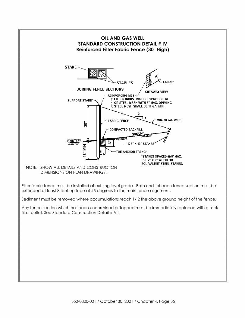
OIL AND GAS WELL
STANDARD CONSTRUCTION DETAIL # IV Reinforced Filter Fabric Fence (30" High)
NOTE: SHOW ALL DETAILS AND CONSTRUCTION DIMENSIONS ON PLAN DRAWINGS.
Filter fabric fence must be installed at existing level grade. Both ends of each fence section must be extended at least 8 feet upslope at 45 degrees to the main fence alignment.
Sediment must be removed where accumulations reach 1/ 2 the above ground height of the fence.
Any fence section which has been undermined or topped must be immediately replaced with a rock filter outlet. See Standard Construction Detail # VII.
550-0300-001 / October 30, 2001 / Chapter 4, Page 35
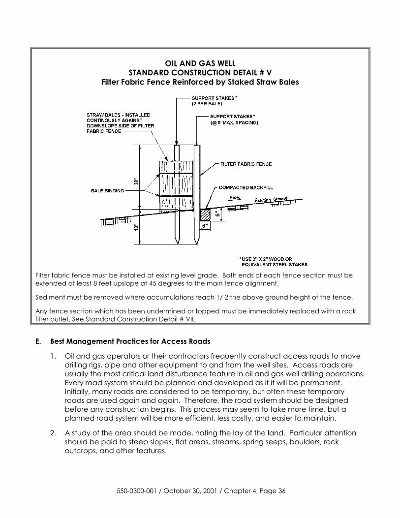
OIL AND GAS WELL
STANDARD CONSTRUCTION DETAIL # V Filter Fabric Fence Reinforced by Staked Straw Bales
Filter fabric fence must be installed at existing level grade. Both ends of each fence section must be extended at least 8 feet upslope at 45 degrees to the main fence alignment.
Sediment must be removed where accumulations reach 1/ 2 the above ground height of the fence.
Any fence section which has been undermined or topped must be immediately replaced with a rock filter outlet. See Standard Construction Detail # VII.
E. Best Management Practices for Access Roads
1. Oil and gas operators or their contractors frequently construct access roads to move drilling rigs, pipe and other equipment to and from the well sites. Access roads are usually the most critical land disturbance feature in oil and gas well drilling operations. Every road system should be planned and developed as if it will be permanent. Initially, many roads are considered to be temporary, but often these temporary roads are used again and again. Therefore, the road system should be designed before any construction begins. This process may seem to take more time, but a planned road system will be more efficient, less costly, and easier to maintain.
2. A study of the area should be made, noting the lay of the land. Particular attention should be paid to steep slopes, flat areas, streams, spring seeps, boulders, rock outcrops, and other features.
550-0300-001 / October 30, 2001 / Chapter 4, Page 36
3. Road specifications will vary according to soil types, slopes and weight of loads to be transported. Soils information is available at the county conservation district office. This information includes the type of soil and the soil features, such as drainage and suitability for a road base, that affect road location and construction.
4. Alignment - The first step in developing a road system is planning the most efficient ingress and egress and then properly locating the system on the ground. Horizontal and vertical alignment should ensure that the road will not cause environmental damage or safety hazards. Cut and fill areas and slopes should be minimized.
5. Grade - Grade is a critical aspect for any road location. Road grades ideally should be kept below 10 percent. When absolutely necessary, grades of up to 15 percent or 20 percent may be used for short distances. However, where such a steep grade is necessary, at least 300 feet of road above and below the steep section should be less than a 10 percent grade. Long steady grades permit the buildup of surface water that increases the erosion potential unless adequate drainage structures are installed. Conversely, a length of road with no grade and drainage may present a serious mud problem.
6. Floodways and drainage ways - Roads must be constructed above flood plains and away from drainage ways when possible. Side hill construction permits good cross drainage. When laying out a road, avoid problem spots such as seeps and springs, when possible. If wet areas are unavoidable, proper drainage measures should be installed.
7. Stream Crossings - Roads shall not be located in perennial or intermittent stream channels or wetlands. Roads should not use stream fords unless approved by the Department. All crossings of perennial streams should be made using approved bridges, culverts or similar structures. Operators should refer to Section III-B for permit requirements for water obstructions and encroachments.
8. Flooding - Roads should not be located where they will cause additional downstream flooding or sediment deposition.
9. Vegetative filter strips - When locating a road upslope of a stream, allow for an adequate filter strip of undisturbed vegetation between the road and the stream. The width of the filter strip will depend on the slope between the road and the stream. Where a sufficient filter strip is not possible due to siting problems, sediment barriers such as filter fabric fences and hay bales must be used. The Table 4-5 provides minimum filter strip width where sheet flow from the road is expected.
550-0300-001 / October 30, 2001 / Chapter 4, Page 37
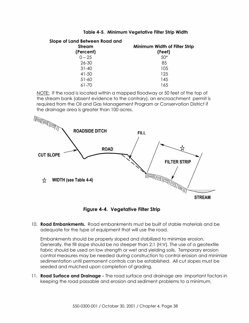
Table 4-5. Minimum Vegetative Filter Strip Width
Slope of Land Between Road and Stream
(Percent) Minimum Width of Filter Strip
(Feet) 0 – 25 50* 26-30 85 31-40 105 41-50 125 51-60 145 61-70 165
NOTE: If the road is located within a mapped floodway or 50 feet of the top of the stream bank (absent evidence to the contrary), an encroachment permit is required from the Oil and Gas Management Program or Conservation District if the drainage area is greater than 100 acres.
ROADSIDE DITCH
ROAD
FILL
FILTER STRIP
STREAM
WIDTH (see Table 4-4)
CUT SLOPE
Figure 4-4. Vegetative Filter Strip
10. Road Embankments. Road embankments must be built of stable materials and be adequate for the type of equipment that will use the road.
Embankments should be properly sloped and stabilized to minimize erosion. Generally, the fill slope should be no steeper than 2:1 (H:V). The use of a geotextile fabric should be used on low strength or wet and yielding soils. Temporary erosion control measures may be needed during construction to control erosion and minimize sedimentation until permanent controls can be established. All cut slopes must be seeded and mulched upon completion of grading.
11. Road Surface and Drainage - The road surface and drainage are important factors in keeping the road passable and erosion and sediment problems to a minimum.
550-0300-001 / October 30, 2001 / Chapter 4, Page 38
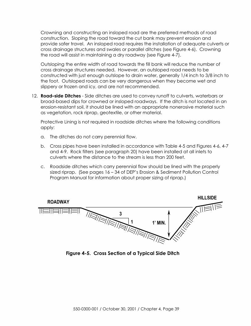
Crowning and constructing an insloped road are the preferred methods of road construction. Sloping the road toward the cut bank may prevent erosion and provide safer travel. An insloped road requires the installation of adequate culverts or cross drainage structures and swales or parallel ditches (see Figure 4-6). Crowning the road will assist in maintaining a dry roadway (see Figure 4-7).
Outsloping the entire width of road towards the fill bank will reduce the number of cross drainage structures needed. However, an outsloped road needs to be constructed with just enough outslope to drain water, generally 1/4 inch to 3/8 inch to the foot. Outsloped roads can be very dangerous when they become wet and slippery or frozen and icy, and are not recommended.
12. Road–side Ditches - Side ditches are used to convey runoff to culverts, waterbars or broad-based dips for crowned or insloped roadways. If the ditch is not located in an erosion-resistant soil, it should be lined with an appropriate nonerosive material such as vegetation, rock riprap, geotextile, or other material.
Protective Lining is not required in roadside ditches where the following conditions apply:
a. The ditches do not carry perennial flow.
b. Cross pipes have been installed in accordance with Table 4-5 and Figures 4-6, 4-7 and 4-9. Rock filters (see paragraph 20) have been installed at all inlets to culverts where the distance to the stream is less than 200 feet.
c. Roadside ditches which carry perennial flow should be lined with the properly sized riprap. (See pages 16 – 34 of DEP’s Erosion & Sediment Pollution Control Program Manual for information about proper sizing of riprap.)
ROADWAYHILLSIDE
31 1’ MIN.
Figure 4-5. Cross Section of a Typical Side Ditch
550-0300-001 / October 30, 2001 / Chapter 4, Page 39
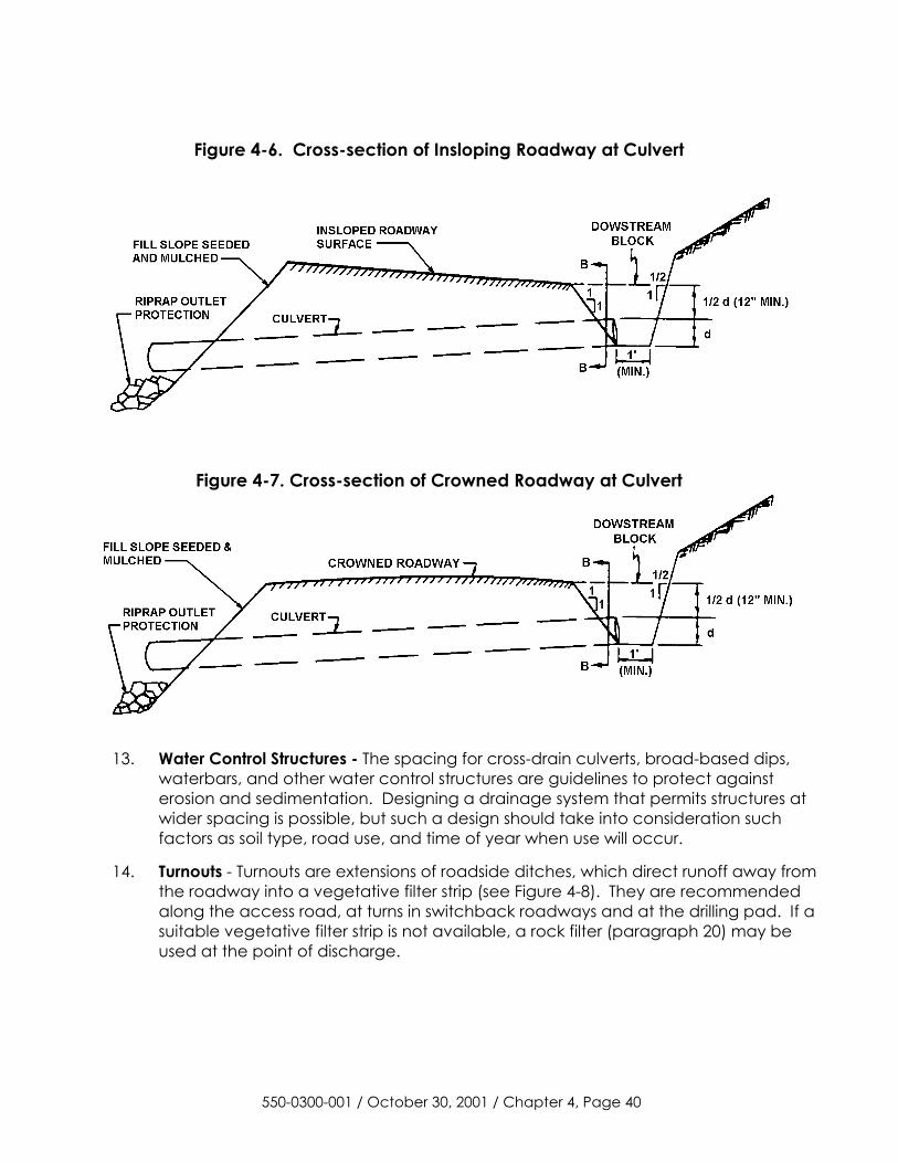
Figure 4-6. Cross-section of Insloping Roadway at Culvert
Figure 4-7. Cross-section of Crowned Roadway at Culvert
13. Water Control Structures - The spacing for cross-drain culverts, broad-based dips, waterbars, and other water control structures are guidelines to protect against erosion and sedimentation. Designing a drainage system that permits structures at wider spacing is possible, but such a design should take into consideration such factors as soil type, road use, and time of year when use will occur.
14. Turnouts - Turnouts are extensions of roadside ditches, which direct runoff away from the roadway into a vegetative filter strip (see Figure 4-8). They are recommended along the access road, at turns in switchback roadways and at the drilling pad. If a suitable vegetative filter strip is not available, a rock filter (paragraph 20) may be used at the point of discharge.
550-0300-001 / October 30, 2001 / Chapter 4, Page 40
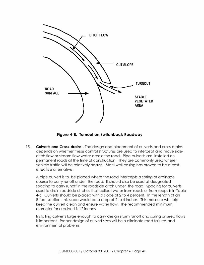
DITCH FLOW
CUT SLOPE
TURNOUT
STABLE,VEGETATEDAREA
ROADSURFACE
Figure 4-8. Turnout on Switchback Roadway
15. Culverts and Cross-drains - The design and placement of culverts and cross-drains depends on whether these control structures are used to intercept and move side-ditch flow or stream flow water across the road. Pipe culverts are installed on permanent roads at the time of construction. They are commonly used where vehicle traffic will be relatively heavy. Steel well casing has proven to be a cost-effective alternative.
A pipe culvert is to be placed where the road intercepts a spring or drainage course to carry runoff under the road. It should also be used at designated spacing to carry runoff in the roadside ditch under the road. Spacing for culverts used to drain roadside ditches that collect water from roads or from seeps is in Table 4-6. Culverts should be placed with a slope of 2 to 4 percent. In the length of an 8-foot section, this slope would be a drop of 2 to 4 inches. This measure will help keep the culvert clean and ensure water flow. The recommended minimum diameter for a culvert is 12 inches.
Installing culverts large enough to carry design storm runoff and spring or seep flows is important. Proper design of culvert sizes will help eliminate road failures and environmental problems.
550-0300-001 / October 30, 2001 / Chapter 4, Page 41
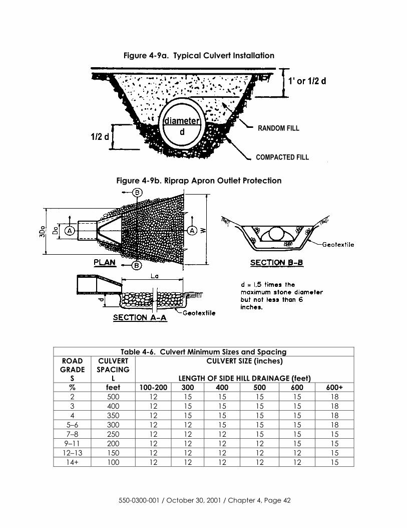
Figure 4-9a. Typical Culvert Installation
RANDOM FILL
COMPACTED FILL
Figure 4-9b. Riprap Apron Outlet Protection
Table 4-6. Culvert Minimum Sizes and Spacing ROAD GRADE
S
CULVERT SPACING
L
CULVERT SIZE (inches)
LENGTH OF SIDE HILL DRAINAGE (feet) % feet 100-200 300 400 500 600 600+ 2 500 12 15 15 15 15 18 3 400 12 15 15 15 15 18 4 350 12 15 15 15 15 18
5–6 300 12 12 15 15 15 18 7–8 250 12 12 12 15 15 15
9–11 200 12 12 12 12 15 15 12–13 150 12 12 12 12 12 15 14+ 100 12 12 12 12 12 15
550-0300-001 / October 30, 2001 / Chapter 4, Page 42
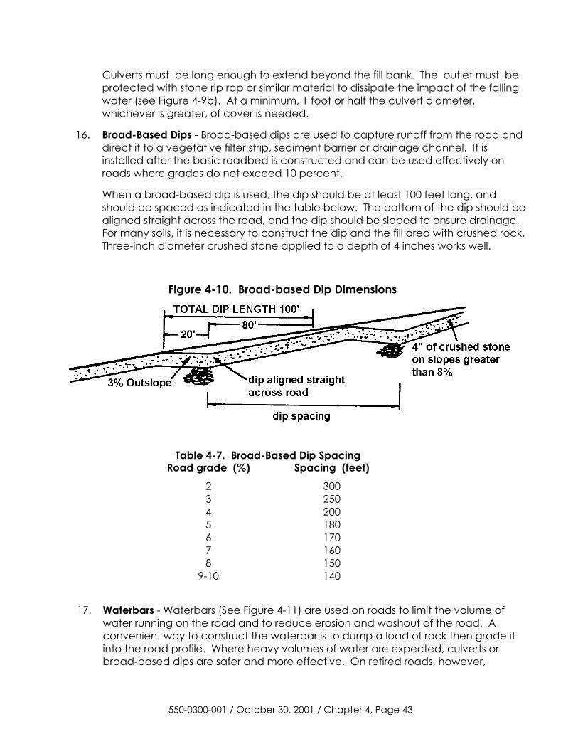
Culverts must be long enough to extend beyond the fill bank. The outlet must be protected with stone rip rap or similar material to dissipate the impact of the falling water (see Figure 4-9b). At a minimum, 1 foot or half the culvert diameter, whichever is greater, of cover is needed.
16. Broad-Based Dips - Broad-based dips are used to capture runoff from the road and direct it to a vegetative filter strip, sediment barrier or drainage channel. It is installed after the basic roadbed is constructed and can be used effectively on roads where grades do not exceed 10 percent.
When a broad-based dip is used, the dip should be at least 100 feet long, and should be spaced as indicated in the table below. The bottom of the dip should be aligned straight across the road, and the dip should be sloped to ensure drainage. For many soils, it is necessary to construct the dip and the fill area with crushed rock. Three-inch diameter crushed stone applied to a depth of 4 inches works well.
Figure 4-10. Broad-based Dip Dimensions
Table 4-7. Broad-Based Dip Spacing
Road grade (%) Spacing (feet) 2 300 3 250 4 200 5 180 6 170 7 160 8 150
9-10 140
17. Waterbars - Waterbars (See Figure 4-11) are used on roads to limit the volume of water running on the road and to reduce erosion and washout of the road. A convenient way to construct the waterbar is to dump a load of rock then grade it into the road profile. Where heavy volumes of water are expected, culverts or broad-based dips are safer and more effective. On retired roads, however,
550-0300-001 / October 30, 2001 / Chapter 4, Page 43
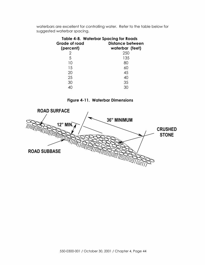
waterbars are excellent for controlling water. Refer to the table below for suggested waterbar spacing.
Table 4-8. Waterbar Spacing for Roads Grade of road
(percent) Distance between
waterbar (feet) 2 250 5 135
10 80 15 60 20 45 25 40 30 35 40 30
Figure 4-11. Waterbar Dimensions
ROAD SUBBASE
ROAD SURFACE
36” MINIMUM 12” MIN.
CRUSHED STONE
550-0300-001 / October 30, 2001 / Chapter 4, Page 44
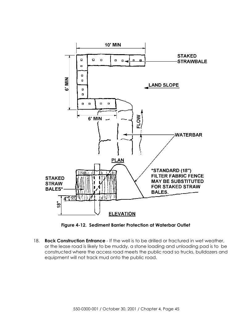
Figure 4-12. Sediment Barrier Protection at Waterbar Outlet
18. Rock Construction Entrance - If the well is to be drilled or fractured in wet weather, or the lease road is likely to be muddy, a stone loading and unloading pad is to be constructed where the access road meets the public road so trucks, bulldozers and equipment will not track mud onto the public road.
550-0300-001 / October 30, 2001 / Chapter 4, Page 45
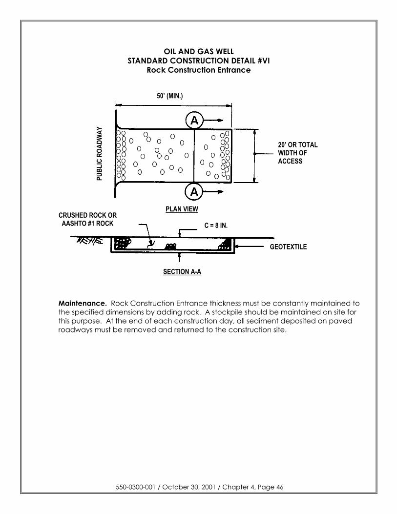
OIL AND GAS WELL STANDARD CONSTRUCTION DETAIL #VI
Rock Construction Entrance
Maintenance. Rock Construction Entrance thickness must be constantly maintained to the specified dimensions by adding rock. A stockpile should be maintained on site for this purpose. At the end of each construction day, all sediment deposited on paved roadways must be removed and returned to the construction site.
550-0300-001 / October 30, 2001 / Chapter 4, Page 46
C = 8”
50’ (MIN.)
PLAN VIEW
20’ OR TOTALWIDTH OFACCESS
PUBL
IC R
OADW
AY
CRUSHED ROCK ORAASHTO #1 ROCK
GEOTEXTILE
SECTION A-A
C = 8 IN.
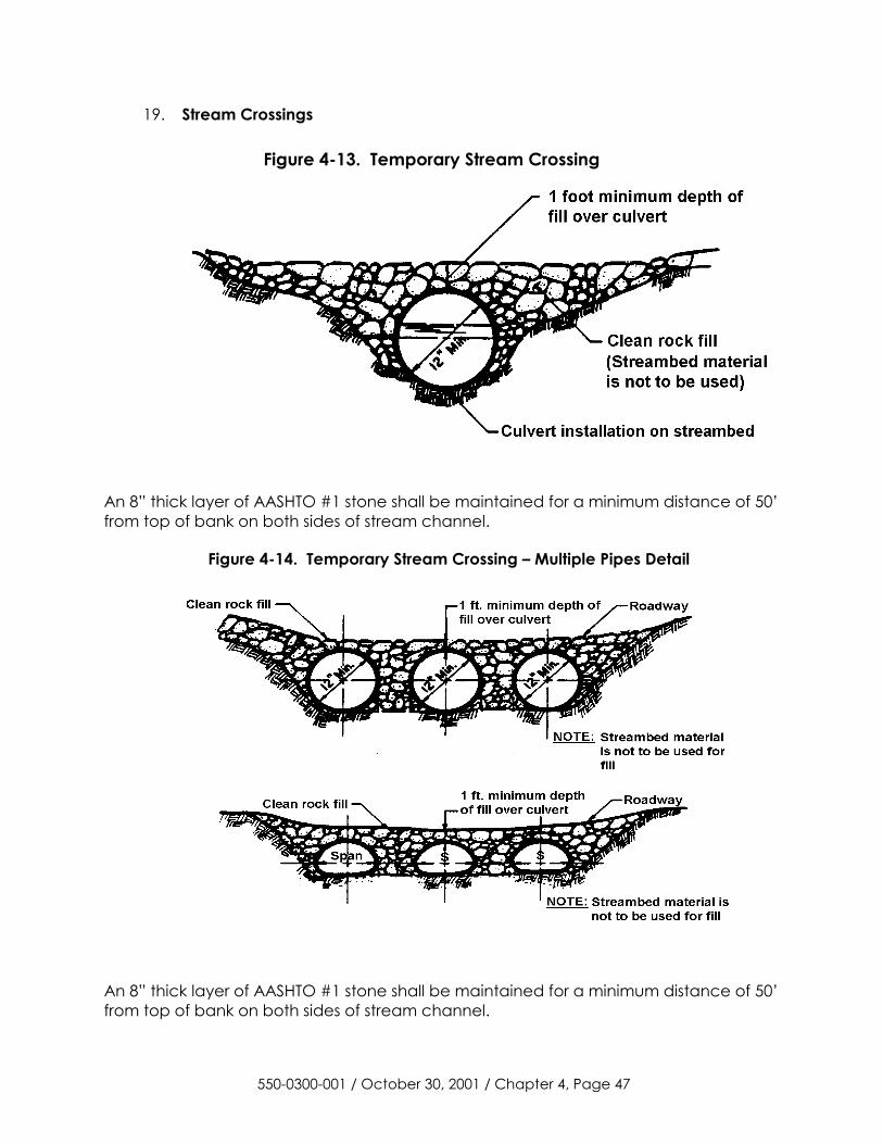
19. Stream Crossings
Figure 4-13. Temporary Stream Crossing
An 8” thick layer of AASHTO #1 stone shall be maintained for a minimum distance of 50’ from top of bank on both sides of stream channel.
Figure 4-14. Temporary Stream Crossing – Multiple Pipes Detail
An 8” thick layer of AASHTO #1 stone shall be maintained for a minimum distance of 50’ from top of bank on both sides of stream channel.
550-0300-001 / October 30, 2001 / Chapter 4, Page 47
20. Rock Filters - Rock filters are used to control runoff within constructed channels until the protective lining is installed and the vegetation is established on the side slopes.
Rock filters may be used to control sediment originating within a channel, either during construction of the channel (before the channel is stabilized) or during a temporary disturbance within the channel. Rock filters may not be used in collector channels in lieu of sediment basins or appropriate channel linings.
Rock filters should be constructed according to the specifications shown in Standard Construction Detail # VII.
Rock filters should be constructed with Riprap sized as follows:
For channels with total depth > 3 feet, use R-4. For channels with total depth between 2 and 3 feet, use R-3. For channels with total depth between 1 and 2 feet, use R-2.
Rock filters should not be used in channels of less than 1 foot deep.
The filter should be equal in height to ½ the total depth of the channel with a 6” depression in the center.
A one-foot thick layer of AASHTO #57 stone should be placed on the upstream side of the filter. NOTE: Filter fabric and straw bales should not be used in rock filters!
Rock filters should be inspected weekly and after each runoff event, and needed repairs should be initiated immediately after the inspection
Clogged filter stone (AASHTO # 57) should be replaced.
550-0300-001 / October 30, 2001 / Chapter 4, Page 48
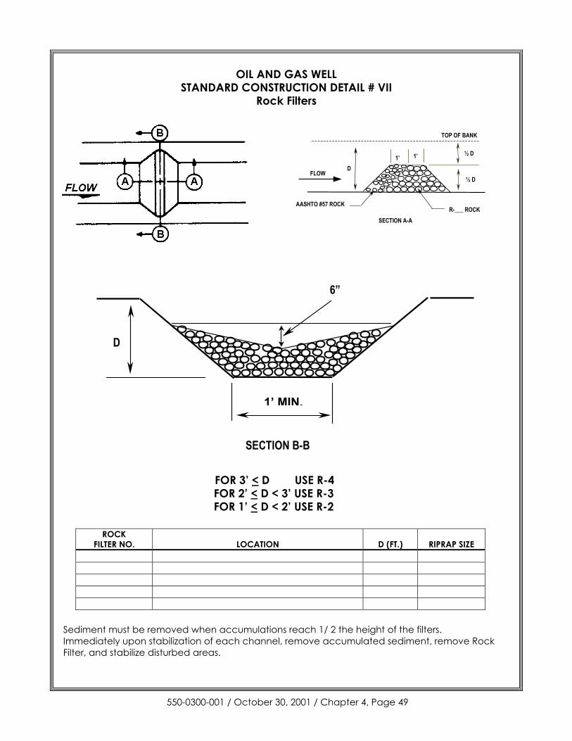
OIL AND GAS WELL STANDARD CONSTRUCTION DETAIL # VII
Rock Filters
FOR 3’ < D FOR 2’ < D < 3’FOR 1’ < D < 2’
ROCK FILTER NO. LOCATION
Sediment must be removed when accumulations Immediately upon stabilization of each channel, reFilter, and stabilize disturbed areas.
550-0300-001 / October 30,
TOP OF BANK
1’ MI
D
SECTION
USE R-4 USE R-3 USE R-2
D (FT.) RIPRAP SIZE
reach 1/ 2 the height of the filters. move accumulated sediment, remove Rock
2001 / Chapter 4, Page 49
DFLOW
1’ 1’ ½ D
½ D
AASHTO #57 ROCKR-___ ROCK
SECTION A-A
N.
6”
B-B
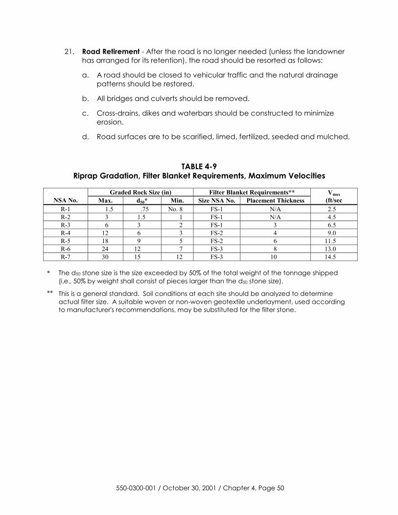
21. Road Retirement - After the road is no longer needed (unless the landowner has arranged for its retention), the road should be resorted as follows:
a. A road should be closed to vehicular traffic and the natural drainage patterns should be restored.
b. All bridges and culverts should be removed.
c. Cross-drains, dikes and waterbars should be constructed to minimize erosion.
d. Road surfaces are to be scarified, limed, fertilized, seeded and mulched.
TABLE 4-9 Riprap Gradation, Filter Blanket Requirements, Maximum Velocities
Graded Rock Size (in) Filter Blanket Requirements**
NSA No. Max. d50* Min. Size NSA No. Placement Thickness Vmax
(ft/sec R-1 1.5 .75 No. 8 FS-1 N/A 2.5 R-2 3 1.5 1 FS-1 N/A 4.5 R-3 6 3 2 FS-1 3 6.5 R-4 12 6 3 FS-2 4 9.0 R-5 18 9 5 FS-2 6 11.5 R-6 24 12 7 FS-3 8 13.0 R-7 30 15 12 FS-3 10 14.5
* The d50 stone size is the size exceeded by 50% of the total weight of the tonnage shipped
(i.e., 50% by weight shall consist of pieces larger than the d50 stone size).
** This is a general standard. Soil conditions at each site should be analyzed to determine actual filter size. A suitable woven or non-woven geotextile underlayment, used according to manufacturer's recommendations, may be substituted for the filter stone.
550-0300-001 / October 30, 2001 / Chapter 4, Page 50

AASHTO NUMBER
NSA NUMBE
R PA
NUMBER 6 1/2 4" 3 1/2" 2 1/2 2" 1 1/2" 1" 3/4" 1/2" 3/8" #4 #8 #16 #30 #100 #200FS-3 100 50 0
1 4 100 90-100 25-60 0-15 0-5
3 3A 100 90-100 35-70 0-15 0-5
467 100 95 35-70 10-30 0--5
FS-2 100 50 0
2A 100 52-100 36-70 24-50 16-38 10-30 0-10
5 100 90-100 20-55 0-10 0-5
57 2B 100 90-100 25-60 0-10 0-5
2 NS 100 90-100 0-15
67 2 100 90-100 20-55 0-10 0-5
1NS 100 90-100 0-15
7 100 90-100 40-70 0-15 0-5
8 100 85-100 10-30 0-10 0-5
1B 100 75-100 10-30 0-10
10 1 100 75-100 10-30
FS-1 100 50 0
550-0300-001 / October 30, 2001 / C
hapter 4, Page 51
TA
BL
E 4-10
Com
parison of Various G
radations of Coarse A
ggregates T
otal Percent Passing
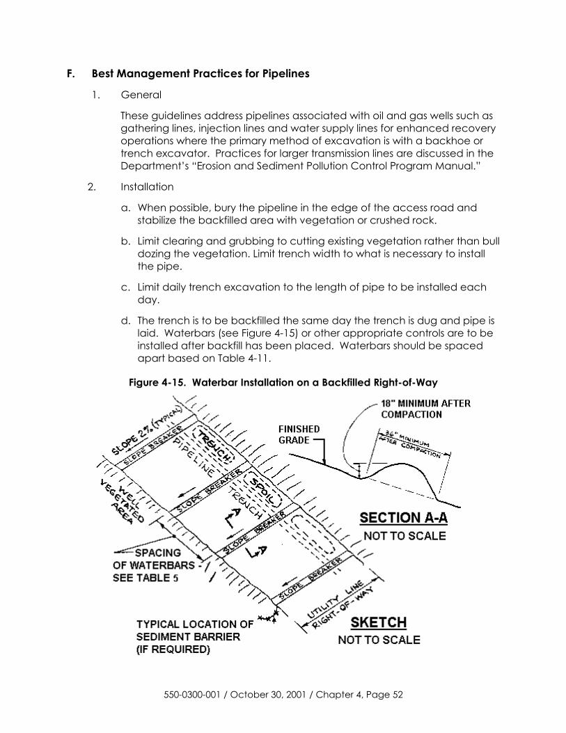
F. Best Management Practices for Pipelines
1. General
These guidelines address pipelines associated with oil and gas wells such as gathering lines, injection lines and water supply lines for enhanced recovery operations where the primary method of excavation is with a backhoe or trench excavator. Practices for larger transmission lines are discussed in the Department’s “Erosion and Sediment Pollution Control Program Manual.”
2. Installation
a. When possible, bury the pipeline in the edge of the access road and stabilize the backfilled area with vegetation or crushed rock.
b. Limit clearing and grubbing to cutting existing vegetation rather than bull dozing the vegetation. Limit trench width to what is necessary to install the pipe.
c. Limit daily trench excavation to the length of pipe to be installed each day.
d. The trench is to be backfilled the same day the trench is dug and pipe is laid. Waterbars (see Figure 4-15) or other appropriate controls are to be installed after backfill has been placed. Waterbars should be spaced apart based on Table 4-11.
Figure 4-15. Waterbar Installation on a Backfilled Right-of-Way
550-0300-001 / October 30, 2001 / Chapter 4, Page 52
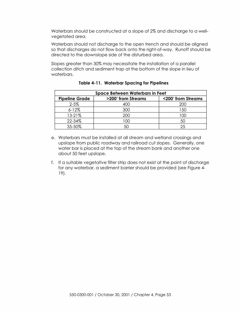
Waterbars should be constructed at a slope of 2% and discharge to a well-vegetated area.
Waterbars should not discharge to the open trench and should be aligned so that discharges do not flow back onto the right-of-way. Runoff should be directed to the downslope side of the disturbed area.
Slopes greater than 30% may necessitate the installation of a parallel collection ditch and sediment trap at the bottom of the slope in lieu of waterbars.
Table 4-11. Waterbar Spacing for Pipelines
Space Between Waterbars in Feet Pipeline Grade >200‘ from Streams <200‘ from Streams
2-5% 400 200 6-12% 300 150
13-21% 200 100 22-34% 100 50 35-50% 50 25
e. Waterbars must be installed at all stream and wetland crossings and
upslope from public roadway and railroad cut slopes. Generally, one water bar is placed at the top of the stream bank and another one about 50 feet upslope.
f. If a suitable vegetative filter strip does not exist at the point of discharge for any waterbar, a sediment barrier should be provided (see Figure 4-19).
550-0300-001 / October 30, 2001 / Chapter 4, Page 53
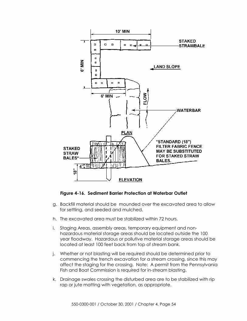
Figure 4-16. Sediment Barrier Protection at Waterbar Outlet
g. Backfill material should be mounded over the excavated area to allow for settling, and seeded and mulched.
h. The excavated area must be stabilized within 72 hours.
i. Staging Areas, assembly areas, temporary equipment and non-hazardous material storage areas should be located outside the 100 year floodway. Hazardous or pollutive material storage areas should be located at least 100 feet back from top of stream bank.
j. Whether or not blasting will be required should be determined prior to commencing the trench excavation for a stream crossing, since this may affect the staging for the crossing. Note: A permit from the Pennsylvania Fish and Boat Commission is required for in-stream blasting.
k. Drainage swales crossing the disturbed area are to be stabilized with rip rap or jute matting with vegetation, as appropriate.
550-0300-001 / October 30, 2001 / Chapter 4, Page 54
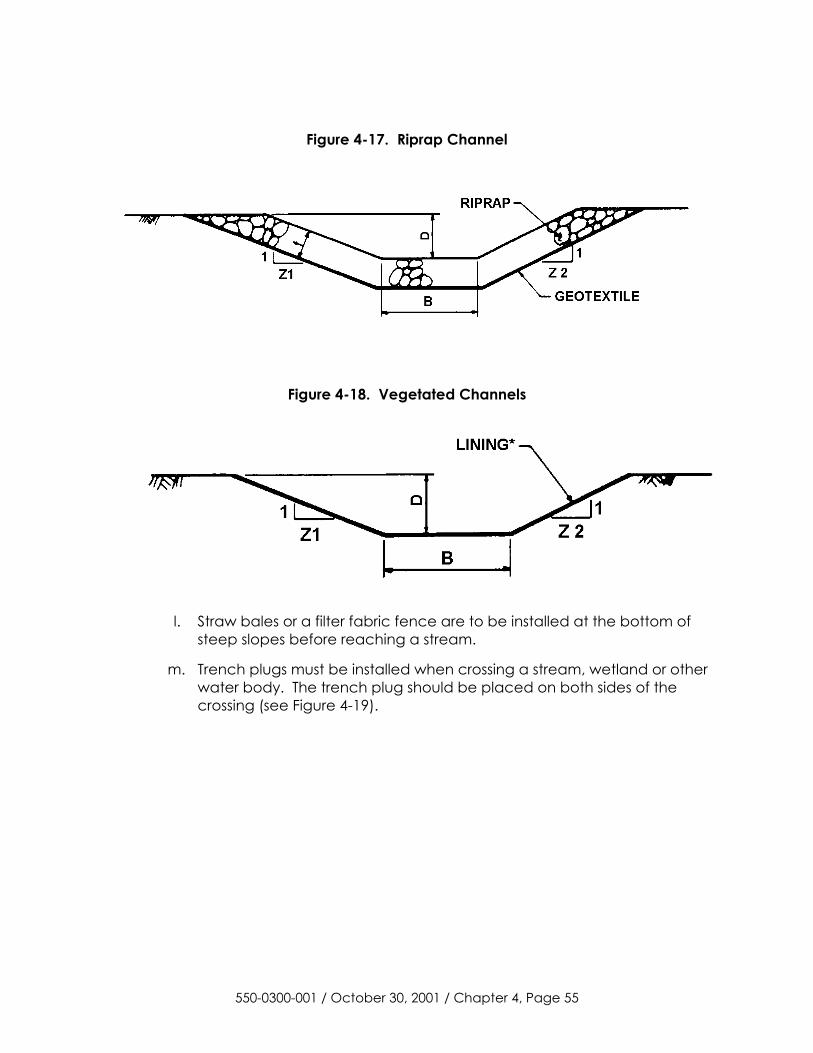
Figure 4-17. Riprap Channel
Figure 4-18. Vegetated Channels
l. Straw bales or a filter fabric fence are to be installed at the bottom of steep slopes before reaching a stream.
m. Trench plugs must be installed when crossing a stream, wetland or other water body. The trench plug should be placed on both sides of the crossing (see Figure 4-19).
550-0300-001 / October 30, 2001 / Chapter 4, Page 55

Figure 4-19. Typical Trench Plug Installation
Table 4-12. Required Spacing and Materials for Trench Plugs Trench Slope (%) Spacing (FT) Plug Material
< 5 * * 5 – 15 500 ** Earth Filled Sacks 15 – 25 300 ** Earth Filled Sacks 25 – 35 200 ** Earth Filled Sacks 35 – 100 100 ** Earth Filled Sacks > 100 50 Cement Filled Bags (Wetted) or
Mortared Stone
* Trench Plugs are required at all stream, river, or water-body crossings regardless of trench slope. Otherwise not required.
** Topsoil may not be used to fill sacks.
550-0300-001 / October 30, 2001 / Chapter 4, Page 56
3. Stream Crossings
a. Chapter 105 encroachment permit must be obtained from the Department before placing a pipeline across a watercourse, floodway or wetland. In most cases, operators can use the general permit BDWM-GP-5 “Utility Line Stream Crossings.“ In areas where the general permit does not apply, operators will need to obtain a small projects permit or an individual permit. These areas are listed in the general permit.
b. Establish the schedule for construction of all access roads, assembly areas and temporary equipment storage areas that will be completed prior to the start of any work within the channel. Seasonal anticipated flow and weather changes should be taken into consideration.
c. Establish a schedule for work within the stream channel that specifies the amount of disturbance and stabilization that will occur each day. Where this is not possible, or practical, develop a schedule that minimizes the overall time required to undertake and stabilize the crossing.
d. If installation of the pipe, backfilling and stabilization will take less than 24 hours, no water diversion is necessary. Otherwise, normal stream flows in small streams (width from 1-10 feet) should be conveyed over any excavation trench by a pipe or culvert. Trench excavation should be undertaken from one side, or simultaneously from both sides, after installation of the normal flow diversion. The upstream and downstream ends of the diversion must be sealed to prevent flows from directly entering the trench. Use this method on streams wider than 10 feet where normal flow can be contained in a culvert and where trench excavation can be done from the top of the stream banks.
550-0300-001 / October 30, 2001 / Chapter 4, Page 57
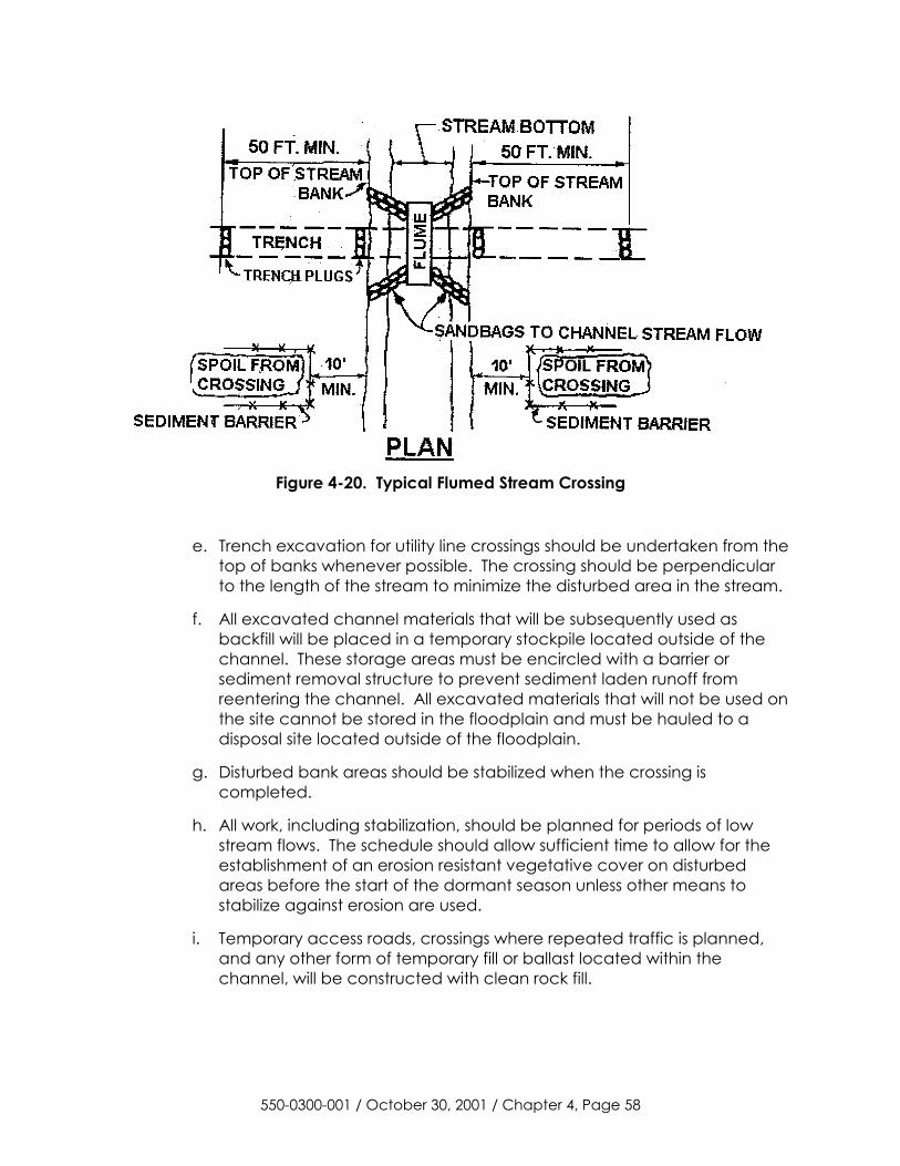
Figure 4-20. Typical Flumed Stream Crossing
e. Trench excavation for utility line crossings should be undertaken from the top of banks whenever possible. The crossing should be perpendicular to the length of the stream to minimize the disturbed area in the stream.
f. All excavated channel materials that will be subsequently used as backfill will be placed in a temporary stockpile located outside of the channel. These storage areas must be encircled with a barrier or sediment removal structure to prevent sediment laden runoff from reentering the channel. All excavated materials that will not be used on the site cannot be stored in the floodplain and must be hauled to a disposal site located outside of the floodplain.
g. Disturbed bank areas should be stabilized when the crossing is completed.
h. All work, including stabilization, should be planned for periods of low stream flows. The schedule should allow sufficient time to allow for the establishment of an erosion resistant vegetative cover on disturbed areas before the start of the dormant season unless other means to stabilize against erosion are used.
i. Temporary access roads, crossings where repeated traffic is planned, and any other form of temporary fill or ballast located within the channel, will be constructed with clean rock fill.
550-0300-001 / October 30, 2001 / Chapter 4, Page 58
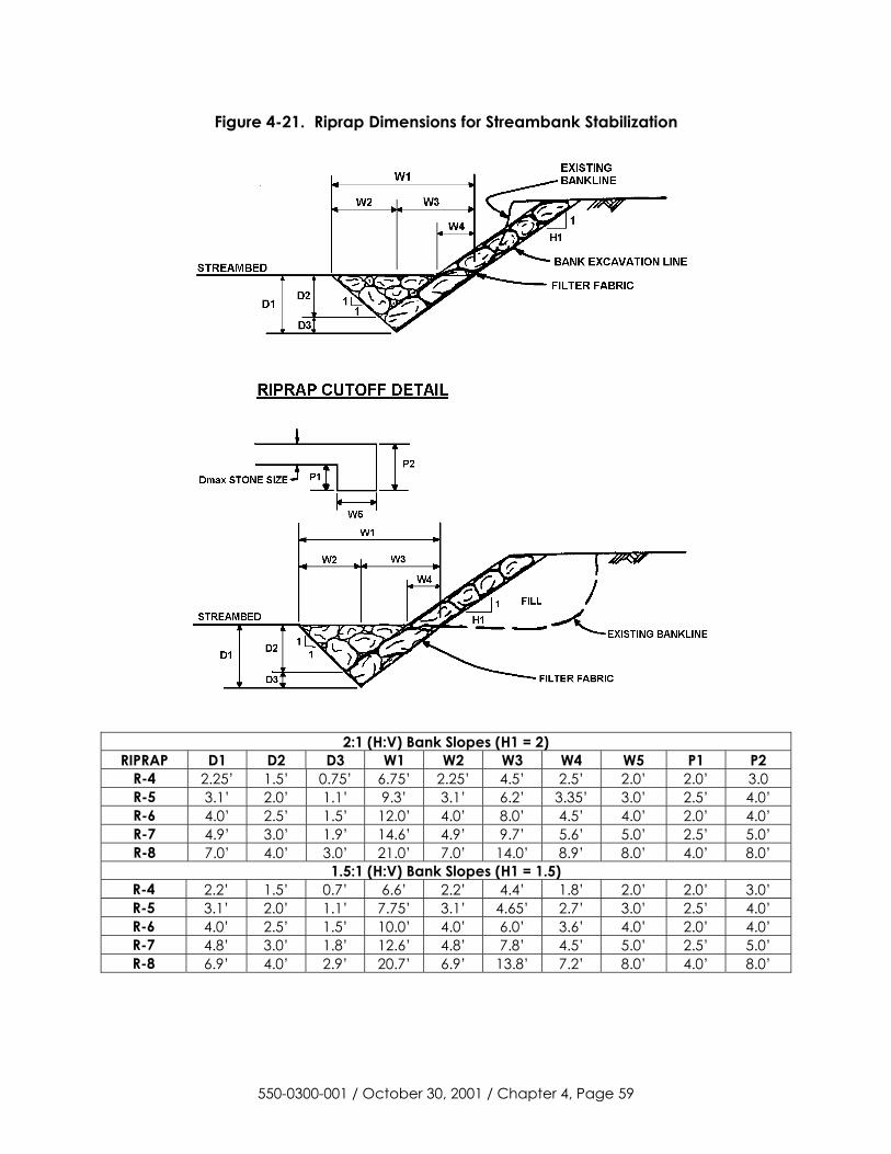
Figure 4-21. Riprap Dimensions for Streambank Stabilization
2:1 (H:V) Bank Slopes (H1 = 2)
RIPRAP D1 D2 D3 W1 W2 W3 W4 W5 P1 P2 R-4 2.25’ 1.5’ 0.75’ 6.75’ 2.25’ 4.5’ 2.5’ 2.0’ 2.0’ 3.0 R-5 3.1’ 2.0’ 1.1’ 9.3’ 3.1’ 6.2’ 3.35’ 3.0’ 2.5’ 4.0’ R-6 4.0’ 2.5’ 1.5’ 12.0’ 4.0’ 8.0’ 4.5’ 4.0’ 2.0’ 4.0’ R-7 4.9’ 3.0’ 1.9’ 14.6’ 4.9’ 9.7’ 5.6’ 5.0’ 2.5’ 5.0’ R-8 7.0’ 4.0’ 3.0’ 21.0’ 7.0’ 14.0’ 8.9’ 8.0’ 4.0’ 8.0’
1.5:1 (H:V) Bank Slopes (H1 = 1.5) R-4 2.2’ 1.5’ 0.7’ 6.6’ 2.2’ 4.4’ 1.8’ 2.0’ 2.0’ 3.0’ R-5 3.1’ 2.0’ 1.1’ 7.75’ 3.1’ 4.65’ 2.7’ 3.0’ 2.5’ 4.0’ R-6 4.0’ 2.5’ 1.5’ 10.0’ 4.0’ 6.0’ 3.6’ 4.0’ 2.0’ 4.0’ R-7 4.8’ 3.0’ 1.8’ 12.6’ 4.8’ 7.8’ 4.5’ 5.0’ 2.5’ 5.0’ R-8 6.9’ 4.0’ 2.9’ 20.7’ 6.9’ 13.8’ 7.2’ 8.0’ 4.0’ 8.0’
550-0300-001 / October 30, 2001 / Chapter 4, Page 59
4. Wetland Crossings
a. Staging areas should be located at least 50 feet from the edge of the wetland.
b. Movement of vehicles across the wetland should be minimized.
c. Excavated topsoil (with the vegetative root mass) should be carefully removed and stockpiled separately from the subsoil (unless there is standing water or the soil is too saturated to segregate).
d. Measures (e.g., clay trench plugs) should be taken to prevent the trench from draining the wetlands or changing its hydrology.
e. Special measures for revegetation should be observed. Lime and fertilizer should not be applied. Annual ryegrass at the rate of 40 lbs./acre should be applied to areas without standing water. Straw mulch should be used at the rate of 3 tons/acre and without binding agents.
5. Road Crossings
The types and locations of best management practices needed at a road crossing depends upon the slope of the land and road drainage systems present at that location.
a. If the open cut method is used, the crossing should be constructed when the road drainage system is dry and it should be backfilled and stabilized the same day. If runoff is present in the road drainage system, the culvert or flume should be used to carry the runoff past the trench until it is backfilled and stabilized.
b. Upslope runoff should be diverted around the work area by the use of waterbars.
c. Sediment barriers should be located downslope of trench storage piles. Such storage piles should not be located in any roadway swale or ditch.
d. Discharges from existing roadway culverts, storm sewers, swales, and ditches should be safely conveyed over any open trench.
e. Suitable inlet protection should be provided for any inlet that may receive runoff from a disturbed area.
f. If the crossing is being made by boring under the road, refer to Department’s “Erosion and Sediment Pollution Control Program Manual” for suitable BMPs.
550-0300-001 / October 30, 2001 / Chapter 4, Page 60
G. Revegetation Best Management Practices
After the earth disturbance activity is completed, the disturbed area must be revegetated. The vegetative cover must be a uniform 70% perennial vegetative cover, with a density capable of resisting accelerated erosion and sedimentation. Another option is to use an acceptable BMP which permanently minimizes accelerated erosion and sedimentation.
1. Seed Mixtures - Standard seed mixtures, such as those described in the Penn State publication “Erosion Control & Conservation Plantings on Noncropland,” that have been shown to be effective in stabilizing disturbed areas in Pennsylvania are recommended. This information is summarized in Tables 13 through 16. Although these recommended mixtures will be suitable for most sites, they may not be desirable for all situations that may be encountered (e.g., a well site located in a residential area). In such instances, the Department should be contacted for additional guidance. The website http://plant-materials.nrcs.usda.gov is another excellent source of information.
a. A seed mix should contain more than one variety of seed and include the application rate (e.g., lb./acre), and germination season.
b. If the area to be vegetated is a Steep Slopes (> 3:1), a steep slope mixture should be used. Other limitations, such as droughty or saturated conditions, acid soils, and shaded areas should also be addressed by the proposed seeding plan (see Tables 13 through 16).
c. Wherever tall fescue is proposed, an endophyte free variety (e.g. Johnstone, Barcel, or Festorina) should be used.
d. Seed mixtures should include a legume. When used in areas difficult to vegetate, legume seed lots should contain a certain amount of hard seed (see Table 13 for recommended specifications). Legume seed must be inoculated in order to form nodules on the roots which fix atmospheric nitrogen. Use only seed which has been freshly and properly inoculated.
e. Warm season grasses may have some limitations for use in erosion control and must be considered when selecting a seed mixture. They grow more slowly during the spring and fall months. They tend to form bunches, rather than sod. Therefore, the coverage may not be as uniform as desired.
550-0300-001 / October 30, 2001 / Chapter 4, Page 61
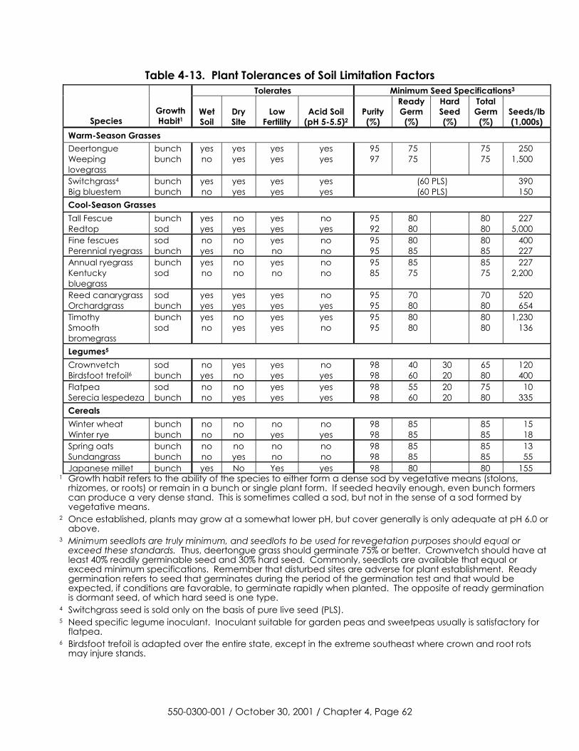
Table 4-13. Plant Tolerances of Soil Limitation Factors Tolerates Minimum Seed Specifications3
Species Growth Habit1
Wet Soil
Dry Site
Low Fertility
Acid Soil (pH 5-5.5)2
Purity (%)
Ready Germ
(%)
Hard Seed (%)
Total Germ
(%) Seeds/lb (1,000s)
Warm-Season Grasses Deertongue Weeping lovegrass
bunch bunch
yes no
yes yes
yes yes
yes yes
95 97
75 75
75 75
250 1,500
Switchgrass4 Big bluestem
bunch bunch
yes no
yes yes
yes yes
yes yes
(60 PLS) (60 PLS)
390 150
Cool-Season Grasses Tall Fescue Redtop
bunch sod
yes yes
no yes
yes yes
no yes
95 92
80 80
80 80
227 5,000
Fine fescues Perennial ryegrass
sod bunch
no yes
no no
yes no
no no
95 95
80 85
80 85
400 227
Annual ryegrass Kentucky bluegrass
bunch sod
yes no
no no
yes no
no no
95 85
85 75
85 75
227 2,200
Reed canarygrass Orchardgrass
sod bunch
yes yes
yes yes
yes yes
no yes
95 95
70 80
70 80
520 654
Timothy Smooth bromegrass
bunch sod
yes no
no yes
yes yes
yes no
95 95
80 80
80 80
1,230 136
Legumes5 Crownvetch Birdsfoot trefoil6
sod bunch
no yes
yes no
yes yes
no yes
98 98
40 60
30 20
65 80
120 400
Flatpea Serecia lespedeza
sod bunch
no no
no yes
yes yes
yes yes
98 98
55 60
20 20
75 80
10 335
Cereals Winter wheat Winter rye
bunch bunch
no no
no no
no yes
no yes
98 98
85 85
85 85
15 18
Spring oats Sundangrass
bunch bunch
no no
no yes
no no
no no
98 98
85 85
85 85
13 55
Japanese millet bunch yes No Yes yes 98 80 80 155 1 Growth habit refers to the ability of the species to either form a dense sod by vegetative means (stolons,
rhizomes, or roots) or remain in a bunch or single plant form. If seeded heavily enough, even bunch formers can produce a very dense stand. This is sometimes called a sod, but not in the sense of a sod formed by vegetative means.
2 Once established, plants may grow at a somewhat lower pH, but cover generally is only adequate at pH 6.0 or above.
3 Minimum seedlots are truly minimum, and seedlots to be used for revegetation purposes should equal or exceed these standards. Thus, deertongue grass should germinate 75% or better. Crownvetch should have at least 40% readily germinable seed and 30% hard seed. Commonly, seedlots are available that equal or exceed minimum specifications. Remember that disturbed sites are adverse for plant establishment. Ready germination refers to seed that germinates during the period of the germination test and that would be expected, if conditions are favorable, to germinate rapidly when planted. The opposite of ready germination is dormant seed, of which hard seed is one type.
4 Switchgrass seed is sold only on the basis of pure live seed (PLS). 5 Need specific legume inoculant. Inoculant suitable for garden peas and sweetpeas usually is satisfactory for
flatpea. 6 Birdsfoot trefoil is adapted over the entire state, except in the extreme southeast where crown and root rots
may injure stands.
550-0300-001 / October 30, 2001 / Chapter 4, Page 62
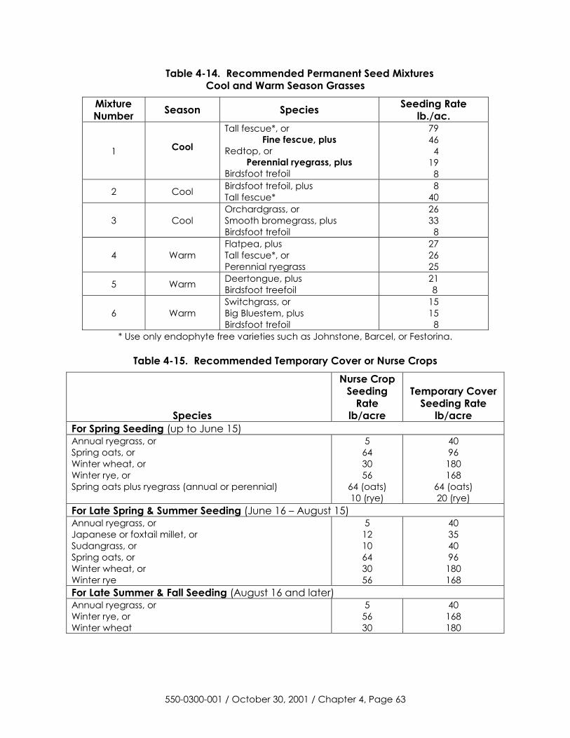
Table 4-14. Recommended Permanent Seed Mixtures Cool and Warm Season Grasses
Mixture Number Season Species Seeding Rate
lb./ac.
1 Cool
Tall fescue*, or Fine fescue, plus
Redtop, or Perennial ryegrass, plus
Birdsfoot trefoil
79 46 4 19 8
2 Cool Birdsfoot trefoil, plus Tall fescue*
8 40
3 Cool Orchardgrass, or Smooth bromegrass, plus Birdsfoot trefoil
26 33 8
4 Warm Flatpea, plus Tall fescue*, or Perennial ryegrass
27 26 25
5 Warm Deertongue, plus Birdsfoot treefoil
21 8
6 Warm Switchgrass, or Big Bluestem, plus Birdsfoot trefoil
15 15 8
* Use only endophyte free varieties such as Johnstone, Barcel, or Festorina.
Table 4-15. Recommended Temporary Cover or Nurse Crops
Species
Nurse Crop Seeding
Rate lb/acre
Temporary Cover Seeding Rate
lb/acre For Spring Seeding (up to June 15) Annual ryegrass, or Spring oats, or Winter wheat, or Winter rye, or Spring oats plus ryegrass (annual or perennial)
5 64 30 56
64 (oats) 10 (rye)
40 96
180 168
64 (oats) 20 (rye)
For Late Spring & Summer Seeding (June 16 – August 15) Annual ryegrass, or Japanese or foxtail millet, or Sudangrass, or Spring oats, or Winter wheat, or Winter rye
5 12 10 64 30 56
40 35 40 96
180 168
For Late Summer & Fall Seeding (August 16 and later) Annual ryegrass, or Winter rye, or Winter wheat
5 56 30
40 168 180
550-0300-001 / October 30, 2001 / Chapter 4, Page 63
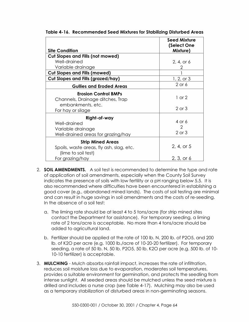
Table 4-16. Recommended Seed Mixtures for Stabilizing Disturbed Areas
Site Condition
Seed Mixture (Select One
Mixture) Cut Slopes and Fills (not mowed)
Well-drained Variable drainage
2, 4, or 6
2 Cut Slopes and Fills (mowed) 1 Cut Slopes and Fills (grazed/hay) 1, 2, or 3
Gullies and Eroded Areas 2 or 6
Erosion Control BMPs Channels, Drainage ditches, Trap embankments, etc. For hay or silage
1 or 2
2 or 3
Right-of-way Well-drained Variable drainage Well-drained areas for grazing/hay
4 or 6
2 2 or 3
Strip Mined Areas Spoils, waste areas, fly ash, slag, etc. (lime to soil test) For grazing/hay
2, 4, or 5
2, 3, or 6
2. SOIL AMENDMENTS. A soil test is recommended to determine the type and rate
of application of soil amendments, especially when the County Soil Survey indicates the presence of soils with low fertility or a pH ranging below 5.5. It is also recommended where difficulties have been encountered in establishing a good cover (e.g., abandoned mined lands). The costs of soil testing are minimal and can result in huge savings in soil amendments and the costs of re-seeding. In the absence of a soil test:
a. The liming rate should be at least 4 to 5 tons/acre (for strip mined sites contact the Department for assistance). For temporary seeding, a liming rate of 2 tons/acre is acceptable. No more than 4 tons/acre should be added to agricultural land.
b. Fertilizer should be applied at the rate of 100 lb. N, 200 lb. of P2O5, and 200 lb. of K2O per acre (e.g. 1000 lb./acre of 10-20-20 fertilizer). For temporary seeding, a rate of 50 lb. N, 50 lb. P2O5, 50 lb. K2O per acre (e.g. 500 lb. of 10-10-10 fertilizer) is acceptable.
3. MULCHING - Mulch absorbs rainfall impact, increases the rate of infiltration, reduces soil moisture loss due to evaporation, moderates soil temperatures, provides a suitable environment for germination, and protects the seedling from intense sunlight. All seeded areas should be mulched unless the seed mixture is drilled and includes a nurse crop (see Table 4-17). Mulching may also be used as a temporary stabilization of disturbed areas in non-germinating seasons.
550-0300-001 / October 30, 2001 / Chapter 4, Page 64
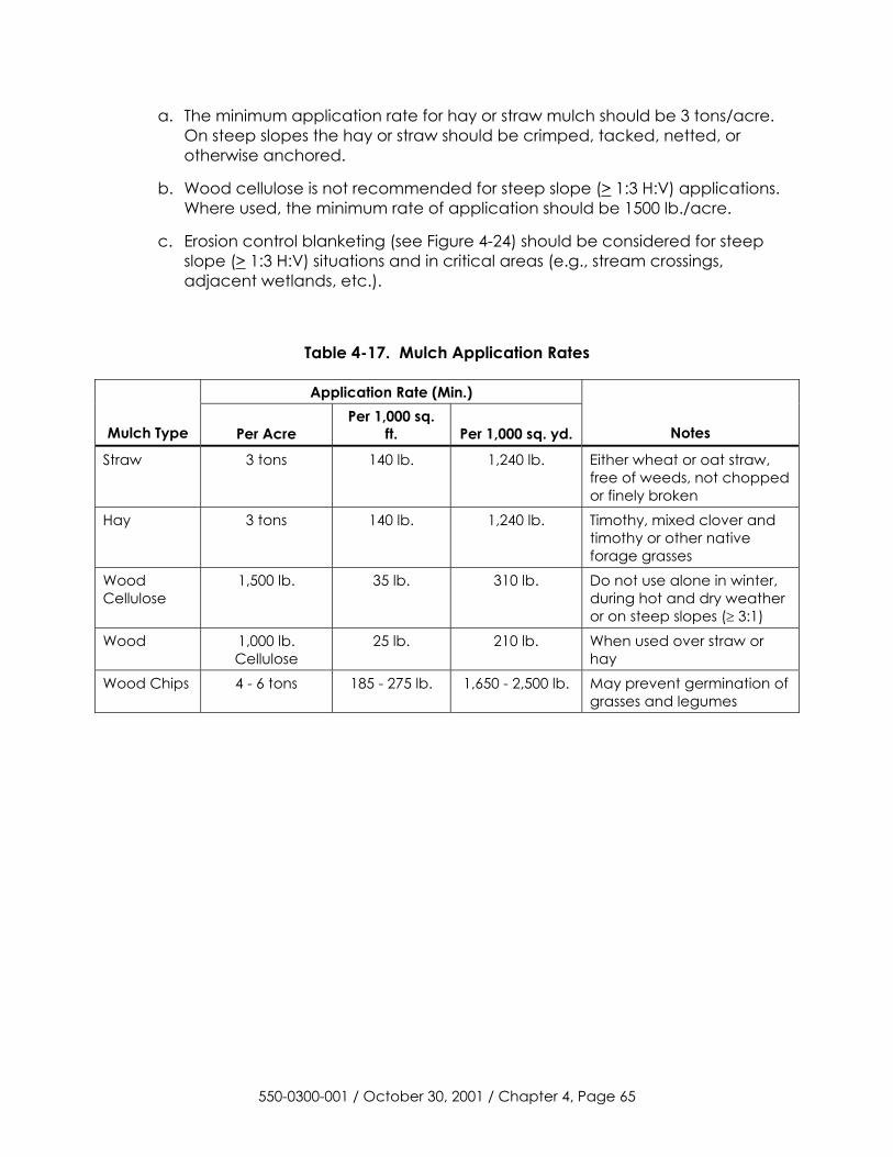
a. The minimum application rate for hay or straw mulch should be 3 tons/acre. On steep slopes the hay or straw should be crimped, tacked, netted, or otherwise anchored.
b. Wood cellulose is not recommended for steep slope (> 1:3 H:V) applications. Where used, the minimum rate of application should be 1500 lb./acre.
c. Erosion control blanketing (see Figure 4-24) should be considered for steep slope (> 1:3 H:V) situations and in critical areas (e.g., stream crossings, adjacent wetlands, etc.).
Table 4-17. Mulch Application Rates
Application Rate (Min.)
Mulch Type Per Acre Per 1,000 sq.
ft. Per 1,000 sq. yd. Notes
Straw 3 tons 140 lb. 1,240 lb. Either wheat or oat straw, free of weeds, not chopped or finely broken
Hay 3 tons 140 lb. 1,240 lb. Timothy, mixed clover and timothy or other native forage grasses
Wood Cellulose
1,500 lb. 35 lb. 310 lb. Do not use alone in winter, during hot and dry weather or on steep slopes (� 3:1)
Wood 1,000 lb. Cellulose
25 lb. 210 lb. When used over straw or hay
Wood Chips 4 - 6 tons 185 - 275 lb. 1,650 - 2,500 lb. May prevent germination of grasses and legumes
550-0300-001 / October 30, 2001 / Chapter 4, Page 65
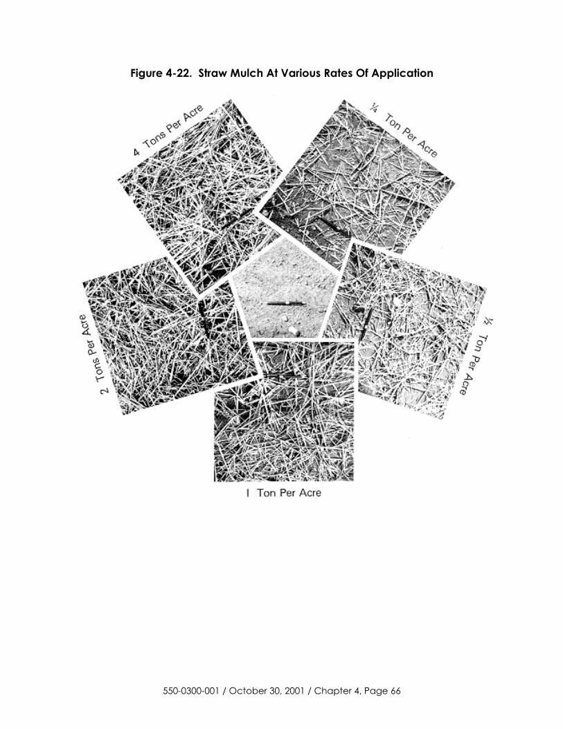
Figure 4-22. Straw Mulch At Various Rates Of Application
550-0300-001 / October 30, 2001 / Chapter 4, Page 66
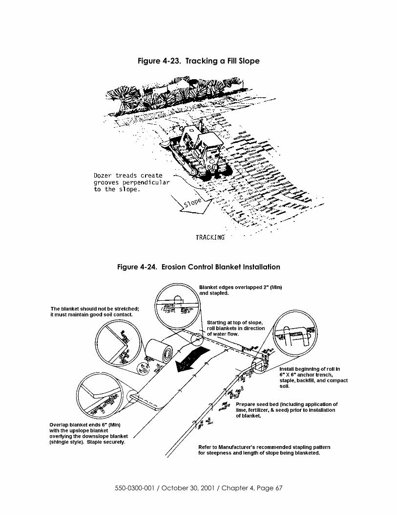
Figure 4-23. Tracking a Fill Slope
Figure 4-24. Erosion Control Blanket Installation
550-0300-001 / October 30, 2001 / Chapter 4, Page 67
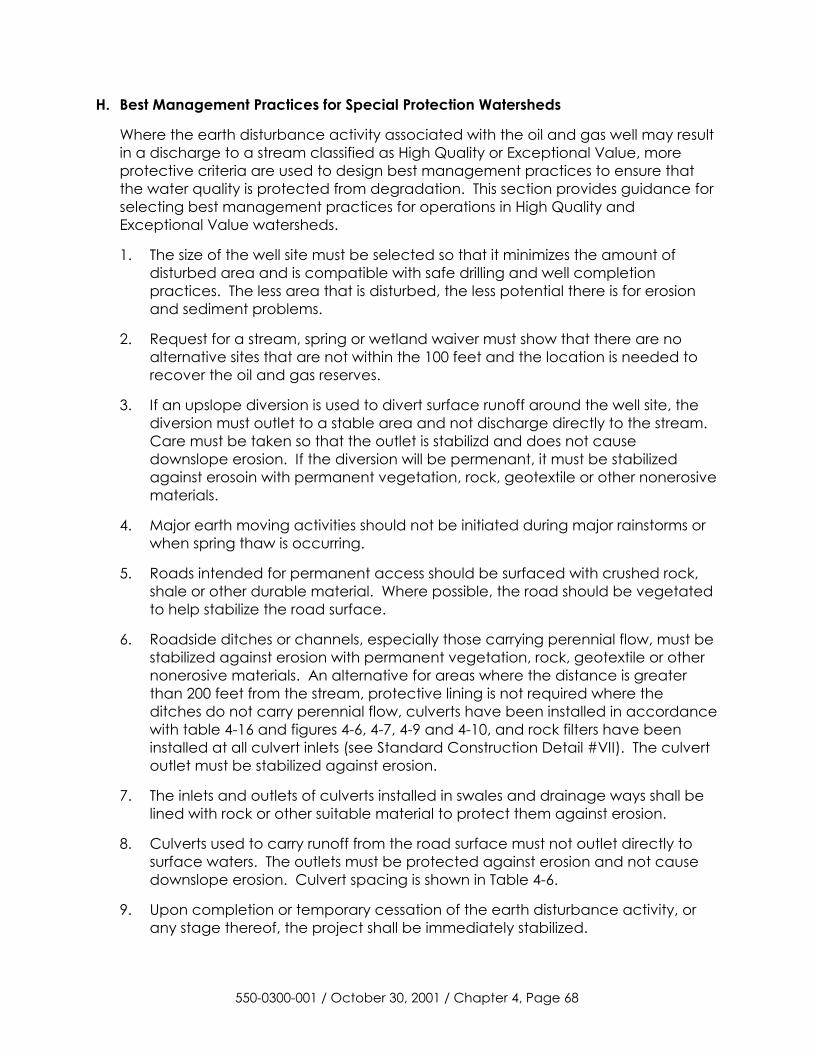
H. Best Management Practices for Special Protection Watersheds
Where the earth disturbance activity associated with the oil and gas well may result in a discharge to a stream classified as High Quality or Exceptional Value, more protective criteria are used to design best management practices to ensure that the water quality is protected from degradation. This section provides guidance for selecting best management practices for operations in High Quality and Exceptional Value watersheds.
1. The size of the well site must be selected so that it minimizes the amount of disturbed area and is compatible with safe drilling and well completion practices. The less area that is disturbed, the less potential there is for erosion and sediment problems.
2. Request for a stream, spring or wetland waiver must show that there are no alternative sites that are not within the 100 feet and the location is needed to recover the oil and gas reserves.
3. If an upslope diversion is used to divert surface runoff around the well site, the diversion must outlet to a stable area and not discharge directly to the stream. Care must be taken so that the outlet is stabilizd and does not cause downslope erosion. If the diversion will be permenant, it must be stabilized against erosoin with permanent vegetation, rock, geotextile or other nonerosive materials.
4. Major earth moving activities should not be initiated during major rainstorms or when spring thaw is occurring.
5. Roads intended for permanent access should be surfaced with crushed rock, shale or other durable material. Where possible, the road should be vegetated to help stabilize the road surface.
6. Roadside ditches or channels, especially those carrying perennial flow, must be stabilized against erosion with permanent vegetation, rock, geotextile or other nonerosive materials. An alternative for areas where the distance is greater than 200 feet from the stream, protective lining is not required where the ditches do not carry perennial flow, culverts have been installed in accordance with table 4-16 and figures 4-6, 4-7, 4-9 and 4-10, and rock filters have been installed at all culvert inlets (see Standard Construction Detail #VII). The culvert outlet must be stabilized against erosion.
7. The inlets and outlets of culverts installed in swales and drainage ways shall be lined with rock or other suitable material to protect them against erosion.
8. Culverts used to carry runoff from the road surface must not outlet directly to surface waters. The outlets must be protected against erosion and not cause downslope erosion. Culvert spacing is shown in Table 4-6.
9. Upon completion or temporary cessation of the earth disturbance activity, or any stage thereof, the project shall be immediately stabilized.
550-0300-001 / October 30, 2001 / Chapter 4, Page 68
10. Areas where vegetative cover will be used for permanent stabilization must be scarified, limed, fertilized, seeded and mulched upon completion of the earth moving activity. During the dormant season, disturbed areas must be mulched and temporary BMPs installed. Successful vegetation must be established within 60 days of the beginning of the next growing season.
11. Temporary BMPs that divert or carry surface water must be designed to have a minimum capacity to convey the peak discharge from a 5-year frequency storm or 2.25 cfs/ac. Permanent channels must be designed to carry the peak discharge from a 10-year frequency storm or 2.75 cfs/ac.
12. The well site should be restored as soon as possible after the well is drilled and completed rather than allowing the site to sit for the maximum of nine months allowed under the Oil and Gas Act.
13. Care must be taken to use best management practices that do not result in a point source discharge or cause degradation of the surface waters.
550-0300-001 / October 30, 2001 / Chapter 4, Page 69

SECTION III
Water Obstructions and Encroachments
The drilling, operating, plugging and maintaining of oil and gas well facilities may involve structures or activities requiring an encroachments permit from DEP. The type of structures and activities normally involved with the oil and gas industry are stream crossings, culverts, bridges, channel changes, fords, fills, water intakes and outfalls. Chapter 3 contains an explanation of the permit requirements.
1. Stream Crossings - Design and Construction Criteria
a. Road Crossing - Culverts and Bridges
(1) The crossing must prevent the restriction of and withstand expected high flows with no interference to the migration of fish.
(2) The structure must not create or constitute a hazard to life, property, or the environment.
(3) Culverts and bridges are to be of sufficient width and size so as not to narrow the existing stream channel.
(4) The structure must not increase the velocity or direct flow so as to result in erosion of stream bed and banks.
(5) Culverts and bridges shall be inspected by the owner on a regular basis to provide for continued operation and maintenance during the lifetime of the structure. Culverts and bridges shall be kept open at all times by maintaining the waterway opening free of debris and other obstructions.
b. Utility Line Stream Crossings
(1) Whenever possible, utility crossings are to be made “in the dry.”
(2) Utility lines in stream beds require a minimum of three feet of cover, except in bedrock, where one foot of cover is required.
(3) Appropriate new or previously excavated backfill material shall be placed in the trench and the area restored to its original condition and elevation and stabilized. The backfilling in which the pipe is laid shall be done so as to eliminate the formation of a permanent ridge in the streambed.
(4) Where applicable, provisions must be made for the shut-off in case of a break or leak in the pipeline.
(5) Mats, pads, or other devices shall be used where crossings of wetland areas are used.
(6) Utility line crossings should be constructed at a right angle to the stream.
550-0300-001 / October 30, 2001 / Chapter 4, Page 70
(7) Aerial crossings attached to bridges are allowed under BDWM-GP-5; they may not be placed below the structure.
c. Intake and Outfall Structures
(1) Each intake and outfall structure must be constructed in a manner so that there is no interference with any navigation on the stream, migration of fish or the passage of flood flows.
(2) Intake structures must be screened or otherwise properly designed to prevent impingement and entrainment of fish.
2. Encroachments in Wetlands
a. An encroachment permit under 25 Pa. Code Chapter 105 must be obtained from DEP to install an encroachment (such as placing fill for an access road or well site) in a wetland.
b. As of February 3, 1996, DEP is using the 1987 U.S. Army Corps of Engineers “Wetlands Delineation Manual” (Technical Report Y-87-1) along with guidance provided by the U.S. Army Corps of Engineers (March 6, 1992).
c. Chapter 105 requires wetlands replacement for projects that fill in wetlands. A Wetlands Delineation and Mitigation Plan is usually required. The operator may create replacement wetlands on the property or if eligible, contribute to the Pennsylvania Wetland Replacement Project. No replacement is required for small (de minimus) wetland impact of less than 1/20 acre.
3. Federal Clean Water Act Section 404 Permits
a. Effective July 1, 2001, the Army Corps of Engineers issued the PASPGP-2 (Pennsylvania State Programmatic General Permit) which indicates that DEP’s Chapter 105 encroachment permit satisfies the federal Clean Water Act Section 404 permit requirement for many of the smaller projects.
b. Permit applications for work in streams, rivers, wetlands, and other waters will be reviewed by DEP. Application for projects that have potential significant environmental impacts will be forwarded to the Army Corps of Engineers (ACOE) for review. All other applications will be processed entirely by DEP. PASPGP-2 places DEP in the lead for processing approximately 80 percent of the state and federal permit applications received.
c. Larger projects will require separate Section 404 (ACOE) and Chapter 105 (DEP) authorizations. The Army Corps of Engineers will review the project and issue a 404 certification separate from the permit issued by the DEP.
4. Fresh Water Intake Structures
a. General Criteria
(1) The intake and any appurtenant structure must not be more than a negligible obstruction to the free flow of the stream. Where the intake
550-0300-001 / October 30, 2001 / Chapter 4, Page 71
structure is large, or where the stream cross-section is small, special attention is required to assure that the intake and appurtenant structure will cause no flooding.
(2) The design of the intake and appurtenant structure must not cause erosion at the intake site.
(3) The withdrawal of water at the intake site must not have a damaging effect on the regimen and ecology of the stream. The fish and aquatic life of the stream shall be preserved.
(4) The withdrawal of water at the intake site must not harm downstream water users or riparian owners. The common law of riparian rights requires that downstream riparian owners are entitled to the flow of the stream undiminished in quantity and unimpaired in quality except to such extent as may result from reasonable and natural use by the riparian owners upstream.
b. Maintenance Requirements
The owner should keep the intake and appurtenant structure properly maintained, with particular attention paid to keeping the intake and intake structure from becoming tangled up with trees, branches, or debris. Such debris shall be removed immediately so that it does not act as an obstruction and cause flooding to properties around the site.
550-0300-001 / October 30, 2001 / Chapter 4, Page 72
SECTION IV -- DRILLING, ALTERING AND COMPLETING A WELL
A. Notification and Local Ordinances
Proper notifications for drilling a well must take place (see Section 201(f) of the Oil and Gas Act). All local ordinances and enactments purporting to regulate oil and gas well operations regulated by the Oil and Gas Act are hereby superseded.
B. Safety Considerations
1. Wells in a Hydrogen Sulfide Area
Well operators should be aware that some wells drilled in Pennsylvania penetrating certain formations have encountered hydrogen sulfide. Requirements of 25 Pa. Code Section 78.77 prescribe procedures and precautions for the operator to follow prior to drilling within a 1-mile radius of a well drilled to or through the same formation where hydrogen sulfide has been found. The regional offices maintain a list of areas where hydrogen sulfide has been encountered while drilling.
2. Casing Requirements and Recommendations
Drilling, casing, cementing, and well completion practices are to be carried out in such a manner to not only enhance the production and protection of oil and gas resources, but to also protect fresh ground water, ensure personal safety for coal miners and the public, and protect the operation of underground gas storage operations.
The gathering of background water quality/quantity data can benefit the operator by avoiding false claims against him. The following procedures are suggested:
a. Proximity to Water Supplies Public and Private (See 25 Pa. Code § 78.52. Predrilling or prealteration survey, Appendix 1). Prior to beginning drilling or site preparation operations, an operator should identify all water sources that have the potential to be affected by their surface or subsurface activities.
b. Proximity of Abandoned, Orphan, and Unplugged Wells
When locating a new well, hydrofracing an existing well, or retrofitting an existing well to function as an enhanced recovery injection well, disposal well or gas storage well, the operator should consider the location of abandoned, orphan and unplugged wells in the area. Abandoned, orphan and unplugged wells, if located within the pressure influence of new activity, may contribute to ground-water and/or surface water pollution incidences and should be plugged.
Prior to beginning actual earthmoving, drilling, fracturing, or retrofitting, all abandoned or orphan unplugged wells within the anticipated affected area should be located and plugging considered. A search for
550-0300-001 / October 30, 2001 / Chapter 4, Page 73
abandoned and orphan unplugged wells should be undertaken by an on-the-ground search and an available map and records search. See 25 Pa. Code § 78.91, Appendix 1 for operator plugging responsibility.
3. Lost Radioactive Sources
Care must be taken when using a radioactive source while logging. If a source is lost while logging a well, the operator must notify the Department and follow procedures as set out in 25 Pa. Code Section 78.111 (See Appendix 1).
C. Casing Design Criteria
All ground-water protective casing, coal protective casing, intermediate casing, and casing used in underground gas storage wells should be in good condition and of sufficient strength to equal or exceed the following minimum design criteria based on industry standards:
Burst Strength - Operators should calculate bottom hole or underground gas storage well pressures and factor in effects of pressure grouting. Casing with a manufacturer’s rated burst strength at least equal to calculated pressures should then be run.
Tension - On long strings of pipe or heavy wall pipe, the total string weight can be quite high (hundreds of thousands of pounds). In such cases, it should be insured that the top joint can sustain the weight of the rest of the pipe in the hole. When running pipe in a crooked hole and when the pipe may need to be worked, several things need to be considered: friction against the wall, whether the hole is dry or fluid filled, the weight of fluid inside pipe, etc. Also, if the pipe needs to be pulled, sufficient tensile strength and joint strength should be provided to ensure the pipe doesn’t part down hole.
Collapse - To allow running through a salt section or shale that caves or flows in on the pipe, adequate collapse strength should be provided.
On deep holes, due to different hole conditions, such as high bottom hole pressure, cavings up hole and weight of a long string of pipe, several types of pipe may be incorporated into one string. Example: high burst and collapse strength pipe in the bottom and a higher tensile pipe near the top of the string.
In addition, the operator shall consider: successful local practices for similar wells, maximum anticipated surface pressure, the chemical environment and the potential for mechanical damage.
1. Fresh Ground-water Protective Casing
Fresh ground water is that ground water in the subsurface portion of the hydrologic cycle which, being in constant motion, retains its fresh water characteristics. When precipitation falls to the earth, a portion infiltrates into the ground, moves downward under the influence of gravity and discharges to the surface as springs and seeps. Depending upon the rock characteristics,
550-0300-001 / October 30, 2001 / Chapter 4, Page 74
this subsurface portion of the hydrologic cycle may take from a few days to tens of years from infiltration to discharge at the surface. Because the water is moving, it tends to retain its fresh water character, although very slowly moving water will show modest increases in dissolved solids.
The base of the moving ground water is limited by the depth of open natural fractures. Pennsylvania rocks are highly fractured as can be seen at any exposed rock outcrop, such as a road cut. With increasing depth, the fractures become progressively closed until movement virtually stops marking the base of the fresh ground-water system (subsurface portion of the hydrologic cycle). Ground-water protective casing must be installed and cemented in accordance with 25 Pa. Code §§ 78.81 - 78.86 (see Appendix 1).
2. Underground Gas Storage Field Casing
Intermediate or production casing used for wells drilled through a gas storage reservoir or a reservoir protective area shall be run at least 100 feet below the gas storage horizon to the surface and be cemented at least 200 feet above the gas storage reservoir or gas storage horizon. It should be installed by mutual agreement between the well operator and the gas storage reservoir operator and approved by the Department. Underground gas storage field casing must be installed and cemented in accordance with 25 Pa. Code §§ 78.81-78.87 and 78.401 (see Appendix 1).
3. Coal Protective Casing
Coal protective casing should be set and cemented at least 30 feet below the lowest workable coal seam. If the coal seam has been removed, the casing should be set and cemented no more than 50 feet below the coal seam. Coal protective casing must be installed and cemented in accordance with 25 Pa. code §§ 78.81-78.86 (see Appendix 1).
4. Alternate Methods
Any plugging, cementing, or casing that occurs not in accordance with procedures set out in either statutes or regulations fall under the category of an alternate method and must be approved by the Department prior to implementation.
5. Defective Casing or Cementing
If a well has casing that is defective or casing that is improperly cemented, the Department shall be notified within 24 hours of the discovery by the operator, and the defect shall be corrected or the operator shall submit a plan to correct the defect for approval by the Department within 30 days. If the defect cannot be corrected or an alternate method is not approved by the Department, the well shall be plugged under Sections 78.91--78.98.
550-0300-001 / October 30, 2001 / Chapter 4, Page 75
D. Fluids Management During Drilling, Completing and Altering a Well
Pollutional substances and wastes from drilling, completing and altering a well must be contained in a pit, tank or series of pits and tanks. This includes pollutional substances and wastes such as: brine, drill cuttings, drilling muds, oils, stimulation fluids, well treatment and servicing fluids, drilling fluids other than gases, and other pollutional substances. The three exceptions are the practice of land application of tophole, disposal of drill cuttings from above the casing seat, and dusting. Additional information on waste management practices is contained in Section V. Also refer to Section I for pollution prevention and waste minimization alternatives.
Section 78.56 of the oil and gas well regulations contains minimum standards for pits and tanks, pit closure requirements and provides for the use of alternative practices. If the use of alternative practices is desired, approval must be obtained from the Department. Requests for the use of alternative practices are to made on form 5500-FM-OG0071 “Request for Approval of Alternative Waste Management Practices“ and must be approved by the Department before utilizing the practices.
550-0300-001 / October 30, 2001 / Chapter 4, Page 76
SECTION V -- WASTE MANAGEMENT DURING DRILLING, ALTERING, OPERATING AND PLUGGING A WELL
Proper control, storage, and disposal or reuse of fluids and waste produced during drilling, operation, servicing and plugging of a well are essential for protection of the environment and prevention of pollution of surface and ground water. The requirements for oil and gas wells are contained in 25 Pa. Code Chapter 78, Subchapter C (See Appendix 1). Pollution prevention practices are discussed in section I.
A. Waste Management Hierarchy
As in any aspect of waste management, there are some general, sound practices that should be employed. These practices, which include waste minimization, not only serve to protect human health and the environment, but also tend to protect waste generators from long-term liabilities associated with waste disposal. Generally, the choice of a waste management option should be based upon the following hierarchy of preference:
1. Source Reduction: Reduce the quantity and/or toxicity of the waste generated.
2. Recycling: Reuse or reclaim as much of the waste generated as possible, and whenever possible, hydrocarbons should be combined with crude oil, condensate, or natural gas liquids.
3. Treatment: Employ techniques to reduce the volume or the toxicity of waste that has been unavoidably generated.
4. Proper Disposal: Dispose of remaining wastes in ways that minimize adverse impacts to the environment and that protect human health.
B. Land Application of Tophole Water
Tophole water is water that is brought to the surface while drilling through the strata containing fresh ground water, and water that is fresh ground water, or water that is from a body of surface water. Tophole water may contain drill cuttings typical of the formation being penetrated, but may not be polluted or contaminated by additives, brine, oil or man induced conditions.
Tophole water and water that accumulates in a pit as a result of precipitation may be applied to the land if the standards of 25 Pa. Code Section 78.60(b) are met. If this practice is to be used, necessary precautions need to be incorporated into the operation so that the fresh water is not combined with other fluids or waste at the site.
C. Disposal of Drill Cuttings From Above the Casing Seat
The oil and gas well regulations recognize two standard practices for the disposal of drill cuttings from above the casing seat: disposal in a pit (Refer to 25 Pa. Code
550-0300-001 / October 30, 2001 / Chapter 4, Page 77
§ 78.61(a)); or disposal by land application (Refer to 25 Pa. Code § 78.61(b)). Since these practices can be readily incorporated into restoration of the site at minimal cost and have broader applicability, the operator should conduct the drilling operation so that the use of this option is maximized by segregating drill cuttings from above the casing seat from other waste. If these drill cuttings are mixed with brines, drilling muds, stimulation fluids, well servicing fluids, oil, production fluids or drilling fluids (other than tophole water, fresh water or gases), they must be disposed of in a lined pit or by controlled land application, see Section D. Section 78.61(d) also provides for the use of solidifiers, dusting, unlined pits, attenuation and other alternative practices. Requests for the use of solidifiers, dusting or other alternative practices are to be made on form 5500-FM-OG0071 "Request for Approval of Alternative Waste Management Practices” and must be approved by the Department before utilizing the practice.
D. Disposal of Drill Cuttings From Below the Casing Seat
For the disposal of drill cuttings from below the casing seat at the well site, the oil and gas regulations identify two standard disposal practices: disposal in a lined pit (Refer to 25 Pa. Code § 78.61(c) in Appendix 1); and disposal by controlled land application (Refer to 25 Pa. Code § 78.61(c) in Appendix 1). These practices are for the disposal of the solid fraction of the drill cuttings after the liquid fraction is removed. If use of solidifiers or other alternative practices is desired, approval must be obtained from the Department. Requests for the use of solidifiers or other alternative practices are to be made on form 5500-FM-OG0071 "Request for Approval of Alternative Waste Management Practices" and must be approved by the Department before utilizing the practice.
Since these wastes can generate leachate that can pollute or contaminate the ground water, pits must be: located at a safe distance from existing buildings, water supplies, streams, bodies of water or wetlands; isolated from the groundwater; constructed with an impermeable liner; and properly closed. (See Section 78.62(a)(5) to (a)(18) and (b) of the oil and gas regulation for specifics).
The requirements for the disposal of drill cuttings from below the casing seat at the well site by land application after removal of the liquid fraction are contained in Section 78.63(a)(5) to (20) and (b) of the oil and gas well regulations. Land application of these drill cuttings must meet the standards in Section 78.63(a)(5) to (20) and (b) of the oil and gas well regulations and be consistent with the “Guidelines For Land Application of Drill Cuttings and Residual Waste” in Appendix 1.
E. Disposal of Residual Waste
Disposal of residual waste (e.g., brines, drilling muds, stimulation fluids, well servicing fluids, oil, production fluids, drilling fluids other than tophole water, or drill cuttings mixed with these substances) must comply with 25 Pa. Code § 78.62 (Disposal of residual waste-pits) and § 78.63 (Disposal of residual waste-land application).
In general, the liquid fraction of the waste (e.g., brine, stimulation fluids, well servicing fluids, drilling fluids) must be removed and disposed of at an approved
550-0300-001 / October 30, 2001 / Chapter 4, Page 78
off-site disposal or treatment facility. Brine from stripper oil wells may be treated and discharged to a stream at the well site if the brine discharge is approved under a NPDES permit (Refer to the “Oil and Gas Wastewater Permitting Manual” in Appendix 5). Before disposing of the liquid fraction, the DEP recommends segregating and recycling any oil that is present.
Operators may dispose of the solids portion of residual waste at the well site by burial in a lined pit and land application. The requirements for disposal in a lined pit are in 25 Pa. Code § 78.62; and the requirements for disposal by controlled land application are in 25 Pa. Code § 78.63 and the “Guidelines for Land Application of Drill Cuttings and Residual Waste.” Information and guidance for the disposal of pit bottoms from pits used to contain production fluids from oil wells is in the report “Characterization and Disposal Options for Oilfield Wastes in Pennsylvania.”
Residual waste can be disposed off-site in permitted landfills. A Form U (Request to Process or Dispose of Residual Waste) must be completed and submitted to the DEP to determine if the waste is acceptable for disposal at a landfill. Contact the Bureau of Land Recycling and Waste Management at a DEP regional office for more information.
Requests for the use of solidifiers or other alternative practices can be made on form 5500-FM-OG00071 “Request for Approval of Alternative Waste Management Practices” and must be approved by the Department before utilizing the practice.
F. Disposal Wells or Injection Wells
Disposal wells or injection wells are the preferred disposal method for brines because it returns the fluids produced from the well to the geologic strata that approximate their point of origin and there is no discharge of the produced fluids to surface or ground water. There are several very successful disposal wells in operation and several oil well operations where a well has been converted to an injector and brine is being reinjected. The history of these wells has shown that underground disposal can be designed and used in Pennsylvania as a practical, safe, effective and adequate method for disposing the brine. In general, disposal wells are suitable for brines, but drilling fluids and fracing fluids may not be compatible with the receiving formation.
The best opportunity for developing a successful disposal well in Pennsylvania exists in the many depleted oil and gas reservoirs scattered throughout the Commonwealth. Depleted gas reservoirs that have sufficient permeability to accept large volumes of water can be made ideal disposal reservoirs when the wells that open to the reservoir can be located and monitored or plugged. Some of the depleted gas fields have been converted to gas storage and the existence of unplugged abandoned wells in other fields can make them difficult to develop for disposal. There are, however, some very successful disposal wells in Pennsylvania.
A well permit for a disposal well or an enhance recovery well is needed from DEP and an underground injection control (UIC) permit is needed from EPA. Additional information on obtaining these two permits is contained in Chapter VIII of the “Oil
550-0300-001 / October 30, 2001 / Chapter 4, Page 79
and Gas Wastewater Permitting Manual.“ Prior to preparation and submittal of a disposal well application, it is recommended that the applicant and/or the design engineer arrange a preliminary technical conference with the Regional Office of the Bureau of Oil and Gas Management. For a listing of the federal requirements of the Underground Injection Control program contact the U.S. EPA Safe Drinking Water Branch, Region III, 841 Chestnut Building, Philadelphia, PA 19107 (215-566-5445).
G. Treatment and Discharge to Surface Waters
As discussed in Chapters 2 and 3 of this Manual, the treatment and discharge of produced fluids or drilling/fracing fluids from oil and gas activities to surface waters is an alternative which may be available, subject to the various state and federal requirements for a discharge. These requirements include obtaining a NPDES permit and a Clean Streams Law Part II Water Quality Management Permit prior to commencing a discharge.
The requirements for treatment and discharge to surface waters are further discussed in the “Oil and Gas Wastewater Permitting Manual,” located in Appendix 5.
H. Discharge to an Existing Treatment Facility
This alternative involves the discharge of wastewater to an industrial waste treatment or sewage treatment facility owned and operated by another party. The success of this alternative depends upon the capability of the facility to treat the wastewater to the point where it is suitable for discharge to surface waters. This alternative may be applicable to the disposal of drilling, stimulation, and production fluids.
The utilization of this disposal alternative may require some degree of pretreatment, or the segregation of drilling and stimulation waste fluids from other production fluids, depending upon the effluent limitations established for discharge at the treatment facility. Pre-treatment of the waste fluids might include pH adjustment and settling of solids before the wastewater is transported to the treatment facility.
Two of the most important factors in determining if the treatment facility can accept the wastewater are its dissolved solids concentration and pH. Total dissolved solids exceeding 10 percent to 20 percent and/or wastewater with a low pH may adversely impact the normal operation of the treatment facility. For this reason, the scheme for discharge of production fluids at treatment facilities may be somewhat different than the discharge of drilling or stimulation fluids. To prevent "shocking" the treatment system with a high concentration of dissolved solids, a reservoir or holding tank may be required to provide a constant, yet low discharge rate into the treatment plant to ensure sufficient dilution of the production waste water.
Any treatment facility receiving oil and gas wastewater for treatment and discharge must operate under Part I NPDES and Part II Water Quality Management Permits and satisfy any pretreatment program requirements. The oil and gas
550-0300-001 / October 30, 2001 / Chapter 4, Page 80
operator does not need a permit to discharge to a treatment facility which operates under such permits. The receiving treatment facility may, however, have to obtain a modified Part I NPDES and/or Part II Water Quality Management Permit to reflect the new conditions of operation.
I. Discharge to a Pretreatment Facility
This alternative involves discharging fluids to a facility which will pretreat the wastewaters, making them acceptable for discharge to a permitted treatment plant. Since the facility does not discharge any wastewater to the waters of the Commonwealth, it is not necessary for the pretreatment facility to have an NPDES or Part II permit. It is, however, necessary that the treatment plants have those permits and have an agreement with the pretreatment facility to accept their discharge. The solids removed by pretreatment must be disposed of at a permitted solid waste management facility.
J. Roadspreading of Brine for Dust Control and Road Stabilization
Produced brine from gas and primary oil wells and other sources (such as brine treatment plants and brine wells) has shown significant promise for beneficial use as a dust suppressant and road stabilizer on unpaved secondary road systems. Due to the pollution potential resulting from the use of brine for road maintenance, the Department has adopted certain restrictions on its use. In doing so, the Department exercises its authority under Section 402 of the Pennsylvania Clean Streams Law (35 P.S. §§ 691.1--691.1001); The Solid Waste Management Act; and Chapters 78.55 and 91.34 of the Rules and Regulations.
In accordance with the Clean Streams Law, it is unlawful to put, place, or allow a discharge of any substance that would result in pollution of the waters of the Commonwealth, including both surface and ground water. The purpose of these guidelines is to minimize the environmental impact resulting from the use of brine for road maintenance. It must be clearly understood that all parties, the brine generator, the transporter, the applicator and the roadway administrator (e.g., PennDOT, municipalities, or private owner) share the responsibility to assure that all activities are conducted in accordance with the following guidelines and in a manner which will not result in pollution of the waters of the Commonwealth.
DEP considers roadspreading of brine for dust control and road stabilization to be a beneficial use of the brine. Brine should only be spread at rates and frequencies necessary to control dust. For excess brine produced from oil and gas wells, operators need to develop alternative disposal options such as deep well disposal or treatment and discharge.
Any person who spreads brine from oil or gas wells or other sources (such as brine treatment plants and brine wells) on unpaved roads for dust suppression and road stabilization must submit a plan on a yearly basis to the DEP for approval. The plan approval can be obtained by the operator, service company, municipality or owner of the road. The plan must show how the potential to pollute is minimized. Approval from DEP must be received before roadspreading can begin.
550-0300-001 / October 30, 2001 / Chapter 4, Page 81

1. The plan is to include the following information:
a. The name, address and telephone number of the person and company seeking the approval and of the person(s) doing the actual spreading. The license plate number of the brine spreader truck(s) is also to be submitted.
b. An original signed and dated statement from the municipality or other person authorizing the use of brine on their roads, and that they will supervise the frequency of spreading.
c. A legible map of the municipality or area identifying the roads which are to receive the brine and brine storage areas not at the well site.
d. A description of how the brine will be applied, including the equipment to be used and the method for controlling the rate of application.
e. The proposed rate and frequency of application.
f. The identification of the geologic formation from which the brines are produced.
g. A chemical analysis of the brine for the following parameters: Sodium Total Dissolved Solids Chloride Calcium Magnesium
DEP will review the plan to determine if all the information requested in items 1 through 7 is present. If the plan is complete and does not show a violation of any operating procedures, an approval will be granted which will expire December 31 for the calendar year roadspreading was requested.
2. The following conditions must be followed when spreading brine:
a. The application of production brine to unpaved roads shall be performed in accordance with the approved plan.
b. The brine shall only be applied at a rate and frequency necessary to suppress dust and stabilize the road. The rate and frequency of application must also be controlled to prevent the brine from flowing or running off into roadside ditches, streams, creeks, lakes and other bodies of water and infiltration to ground water.
c. Spreading rates: The road should initially be spread at a rate up to one-half gallon per square yard (typically after the road has been graded in the spring). The road should subsequently be spread at a rate of up to one-third gallon per square yard no more than once per month unless based on weather conditions, traffic volume or brine characteristics a greater frequency is needed to control dust and stabilize the road. The application rate for race tracks and mining haul roads should be determined for each site and shall not exceed one gallon per square yard.
550-0300-001 / October 30, 2001 / Chapter 4, Page 82
d. Only production brines may be used. The use of drilling, fracing, or plugging fluids or production brines mixed with well servicing or treatment fluids, except detergents, is prohibited. Free oil needs to be separated from the brine before spreading.
e. Brine shall not be applied within one hundred fifty feet of a stream, creek, lake or other body of water.
f. Brine must be spread by use of a spreader bar with shut off controls in the cab of the truck.
g. Brine shall not be placed on roads or parts thereof which have a grade in excess of ten percent (10%).
h. Brine shall not be spread on wet roads, during rain, or when rain is imminent.
i. Each vehicle utilized to spread brine shall have a clearly legible sign identifying the applicator on both sides of the vehicle.
j. The company spreading the brine shall notify the appropriate regional DEP Oil and Gas Office the business day before spreading brine.
k. The producing oil and gas wells must be in compliance with the bonding requirements of the Oil and Gas Act.
l. The person who received the approval of the roadspreading plan shall submit a monthly report (5500-FM-OG0046) to the DEP indicating the location and the amount of brine spread during the month. This monthly brine spreading report must be submitted by the 15th day following the month in which the production brine was spread. This report must be submitted even if no spreading took place during that month.
m. Any revisions to the plan must be submitted to the Department for approval. Approval must be obtained prior to implementation of the revisions.
n. Failure to comply with all these conditions may result in the Department rescinding the plan approval.
K. Evaporation
Natural evaporation from open holding ponds as a waste fluid disposal alternative is not a viable year round alternative in the Commonwealth. The average yearly precipitation throughout the state exceeds evapotranspiration by 10 to 24 inches. As a result, uncovered impoundments that may be utilized to evaporate waste water would increase in fluid volume from precipitation rather than decrease in volume through evaporation. Only during selected months does evaporation occur at a significant rate in Pennsylvania. However, even during these months, precipitation may exceed the reported evaporation rate.
550-0300-001 / October 30, 2001 / Chapter 4, Page 83

Innovative systems that enhance evaporation artificially, however, may be viable methods of waste water reduction or disposal. While no discharge is planned at an evaporation facility, the activity will need an approval or permit from the Department. If the evaporation facility is located at the well site, a PPC plan approval will be needed from the Bureau of Oil and Gas Management. If a pit is involved, a pit approval number under 25 Pa. Code Section 78.57 will need to be obtained.
If the evaporation facility is not located at the well site, a permit for a residual waste processing facility under 25 Pa. Code Chapters 287 and 297 will need to be obtained (see section K).
Based on data now available, it appears deep and shallow gas well brine and primary oil well brine contain more than two pounds of dissolved solids per gallon of fluid. Produced fluids from secondary recovery oil operations, while less concentrated may contain nearly 3/4’s of a pound of dissolved solids per gallon. This solid residue may be subject to Residual Waste Regulations and must be disposed of in an approved manner.
L. Off-Site Solids Disposal
Before disposing of waste at an existing permitted residual waste disposal facility (landfill), a “Form U” (2540-OM-LRWM0395) will need to be prepared and submitted to the DEP for approval. The purpose of the “Form U“ is to verify that the proposed waste is compatible with the disposal facility.
If it is proposed that the waste will be disposed at a new or unpermitted residual waste disposal facility located off the well site, a residual waste disposal permit will need to be obtained for the facility under 25 Pa. Code Chapters 287-291. Contact the DEP‘s regional Land Recycling and Waste Management Program for additional information on this type of facility.
M. Residual Wastes Transfer Stations and Residual Waste Processing Facilities
A transfer facility is a facility which receives and processes or temporarily stores residual waste at a location other than the generation site, and which facilitates the transportation or transfer of the waste to a processing or disposal facility. An example of a transfer facility associated with oil and gas exploration and development is a brine storage area not located at the well site. A permit for a residual waste transfer facility must be obtained from the Department. The requirements for transfer facilities are contained in 25 Pa. Code Chapters 287 and 293.
A residual waste processing permit is needed for a facility that includes a method or technology used for the purpose of reducing the volume or bulk of residual waste, or a method or technology used to convert part of all of the waste materials for offsite reuse. An example of a processing facility is an enhanced evaporation facility. If the facility is located off the well site, a residual waste processing permit would be needed. The requirements for processing facilities are contained in 25 Pa. Code Chapters 287 and 297.
550-0300-001 / October 30, 2001 / Chapter 4, Page 84
N. Transportation of Wastes
In general, the waste must be collected and transported in a manner that does not cause a nuisance or a hazard to public health, safety, welfare or environment. The requirements for collecting and transporting residual waste are contained in 25 Pa. Code 299.201 - 299.232. There are requirements for equipment, accident prevention, emergencies, spills, record keeping and reporting. These requirements apply when waste is being transported off the well site for disposal, processing or beneficial use.
Accident Prevention and Contingency Plan. An accident prevention and contingency plan to minimize and abate a discharge of waste during transportation must be prepared, and a copy of the plan must be kept in the cab of each transportation vehicle.
Emergencies. In the event of a discharge or release of residual waste during transportation, the transported must immediately telephone the Department. In addition, the transporter must immediately clean up the waste and take any other action so the discharge presents no threat to public health, safety, welfare and the environment.
Signs on Vehicles. The Vehicle transporting the waste shall bear a sign with six inch letters that includes the name and address of the owner and the type of waste being transported (refer to 25 Pa. Code 299.220).
Record Keeping and Reporting. Transporters of residual waste must keep an operational record for each day that residual waste is collected and transported. The daily record shall be kept in the cab of the vehicle on the date of collection or transportation and include the following:
• Types or classifications of residual waste transported.
• The weight or volume of the types of waste transported.
• The name, mailing address, telephone number, county and state of each generator of transported waste.
• The name and location of a transfer facility that has received, or will receive, the waste.
• The name and location of the solid waste processing or disposal facility where the waste will be ultimately disposed or processed.
• A description of handling problems or emergency disposal activities.
• The name and address of the person or municipality collecting or transporting the waste.
• The license plate number of the transfer trailer transporting the waste.
The daily records shall be available to the Department upon request and be retained for at least five years.
550-0300-001 / October 30, 2001 / Chapter 4, Page 85
SECTION VI -- WELL SITE RESTORATION
A. Well Site Restoration
1. Within nine months after completion of drilling the well, the oil and gas well owner or operator must restore the land surface within the area disturbed in siting, drilling, completing and producing the well. This includes:
a. Removing or filling all pits used to contain produced fluids or industrial wastes. Standards for disposal of drill cuttings and wastes, and closing the pits are discussed in Section V.
b. Implementing erosion and sediment control measures to minimize the potential for accelerated erosion and sedimentation. Standards for erosion and sediment control area discussed in Section II.
c. Removing all drilling supplies not needed for production. Drilling supplies and equipment not needed for production may be stored at the well site if the express written consent of the surface landowner is obtained.
2. Within nine months after plugging a well, the owner or operator must remove all production or storage facilities, supplies and equipment and restore the well site.
3. The Department may extend the restoration period for an additional six months upon application of the well owner or operator providing evidence of inability to comply due to adverse weather conditions or lack of essential fuel, equipment or labor.
4. Requirements for site restoration are contained in Sections 206 and 603.1 of the Oil and Gas Act and 25 Pa. Code §§ 78.53 to 78.65 of the Oil and Gas Well Regulations (refer to Appendix 1).
B. Well Site Restoration Report
Within 60 days after the restoration of the well, the operator must submit a “Well Site Restoration Report” to the Department. The report is to be made using form 5500-FM-OF0075 “Well Site Restoration Report” (refer to Appendix 1). The report contains information on land application of tophole water, on-site waste disposal, and on-site cutting and waste disposal. Waste volumes reported on this form are not to be included on the “Annual Well and Waste Production Report.”
550-0300-001 / October 30, 2001 / Chapter 4, Page 86
SECTION VII -- WELL OPERATION
A. General Provisions
The goal of the operator in operating a well shall be to prevent gas or other fluids from lower formations from entering fresh groundwater.
B. Oil Storage Tanks and Containment (Dikes)
1. In order to prevent release of a significant quantity of oil from reaching the waters of the Commonwealth, and to protect life, health and property, storage tanks of 660 gallons each or a combined capacity of 1,320 gallons which containing crude oil must have a spill containment system. (Refer to 25 Pa. Code § 78.64 in Appendix 1).
Containment areas must be constructed to:
a. Have a capacity sufficient to hold the volume of the largest single tank, plus a reasonable allowance for precipitation based on local weather conditions and facility operation.
b. Be sufficiently impervious to contain spilled materials or wastes until it can be removed or treated.
c. Be compatible with the material or waste stored.
d. Provide for drainage of precipitation on an as-needed basis. Drainage lines must be kept closed at all times unless actual drainage is in progress. Drainage must be conducted under responsible supervision and must not cause a harmful discharge or sheen.
The Operator’s Preparedness, Prevention and Contingency (PPC) plan should identify the procedures, necessary equipment and personnel, including their location and response time, required to remove or treat spilled materials in an efficient and expedient manner to prevent pollution.
2. Underground and Aboveground Storage Tanks not Related to Oil or Gas Production
Many of the tanks used during oil and gas exploration and production are exempt from the Storage Tank and Spill Prevention Act, however, there are some tanks that must registered with the DEP and meet the tank installation and operating requirements.
Regulated tanks include aboveground and underground storage tanks that store regulated substances such as petroleum and hazardous substances. An aboveground storage tank is a stationary tank with a capacity of more than 250 gallons that has more than 90% of its volume (including the volume of pipes) above supporting grade, and can be visually inspected from the exterior. An underground storage tank is a tank with a capacity more than 110
550-0300-001 / October 30, 2001 / Chapter 4, Page 87
gallons that has 10% or more of its volume (including the volume in the underground pipes) beneath the surface of the ground.
Regulated tanks do not include:
• Tanks which are used to store brines, crude oil, drilling or frac fluids and similar substances or materials and are directly related to the exploration, development or production of crude oil or natural gas regulated under the Oil and Gas Act. This includes tanks located at a well site, a disposal well, or a treatment facility which are covered in the operator‘s Control and Disposal Plan, or PPC Plan.
• A nonstationary tank liquid trap or associated gathering lines directly related to oil and gas production or gathering operations.
• A flow-through process tank, including, but not limited to, a pressure vessel or process vessel and oil and water separators. This includes tanks used for treating fluids at brine treatment plants.
For information on regulated storage tanks, call the DEP Storage Tank Program in the appropriate regional office.
C. Fluids Management During Operation, Servicing and Plugging Activities
Brine and other fluids produced during operation, service and plugging of a well must be collected in a tank, pit or other device approved by the Department. Discharging the brine or other fluids on or into the ground or into the surface or ground water is prohibited 25 Pa. Code § 78.57(a). Section IV contains information on disposal and reuse options for the wastes generated.
If a pit is to be used for control, handling or storage of the brine or other fluids, the operator must obtain a pit authorization number for the pit (unless the pit is approved under a Clean Streams Law permit). Sections 78.57 and 78.58 of the oil and gas well regulations contain the requirements for new and existing pits, and Section 78.56 contains the requirements for pits used for servicing and plugging.
Request for authorization of a pit for control, handling and storage of production fluids is to be made using form 5500-FM-OG0072 "Request for Approval of a Pit for the Control, Handling or Storage of Production Fluids."
D. Annual Well and Waste Production Report
Each operator is to submit an annual well and waste production report specifying the status of and production from each well. The report is to be submitted by March 31 each year for the preceding calendar year. Hardcopy (paper) reports should be on report form (5500-FM-OG0049). If you use a different format, it must have prior approval. We encourage you to use computerized magnetic media (disk or tape) to fulfill this reporting requirement. Prior approval of computerized reports comes from the Bureau’s Systems Coordinator. Inquiries on format are to be directed to him at (717) 772-2199.
550-0300-001 / October 30, 2001 / Chapter 4, Page 88
Production reports are kept confidential for a period of five (5) years. By submitting the waste information to the Oil and Gas Management Program, you do not have to submit a separate report to the Bureau of Land Recycling and Waste Management.
If you use a hard copy (paper) report such as computer printouts, your report must have all the information required by the 5500-FM-OG0049 form and in the same order (field sequence). Refer to Appendix 2 for comparison of the required information and order.
E. Pipeline Operation and Maintenance
Oil pipelines, gathering lines, and associated facilities must be planned, operated, inspected and maintained in a manner to prevent leaks and spills. The planning must consider emergency spill response procedures, equipment and personnel needs.
1. Pump stations and pipeline operations plans should include:
a. A schematic diagram (pump station).
b. Pipelines and pump stations plotted on an appropriate map.
c. Pumping schedule and flow direction.
d. Operational steps in chronological order to prevent and detect leaks.
e. Procedures to follow during equipment breakdown to prevent spills and leaks.
f. Monitoring maintenance and inspections schedules.
g. Personnel training.
h. Communication and chain of command.
i. Protection from external factors.
2. A PPC plan for oil pipelines should also include:
a. Operators history of past incidents.
b. Notification of incident (plan).
c. Clean-up, personnel, equipment and response time.
d. Equipment including charts indicating equipment and location by watershed.
e. Contractors including charts indicating equipment and location.
F. Oil and Gas Separators
Fluids resulting from oil and gas separation including: primary and enhanced oil recovery, gas production and gas storage wells, the removal of water directly from
550-0300-001 / October 30, 2001 / Chapter 4, Page 89

gas wells by pumping, bailing or adding soap sticks and blowing off excess water and any other means of separating fluids must be controlled and handled in a manner to prevent pollution.
550-0300-001 / October 30, 2001 / Chapter 4, Page 90
SECTION VIII - REPORTS
Reports Required of Oil and Gas Well Operators
1. A Well Record is due 30 days after the cessation of drilling. The Well Record includes the driller's log, and details about cement, casing and tubing. Use form 5500-FM-OG0004, Well Record and Completion Report. For convenience it may be submitted at the same time as the Well Completion Report on the same form, provided it would be a timely submittal of both reports. (Oil and Gas Act, Section 212(b); and 25 Pa. Code Section 78.122(a)).
2. A Well Completion Report is due 30 days after well completion. The completion report includes details of the perforation, stimulation, flow and pressure before and after treatment. Also it includes the name and addresses of the service companies that did the work. Use form 5500-FM-OG0004, Well Record and Completion Report. For convenience it may be submitted at the same time as the Well Record report on the same form, provided it would be a timely submittal of both reports. (Oil and Gas Act, Section 212(b); and 25 Pa. Code § 78.122(b)).
3. A Well Site Restoration Report is due 60 days after restoration of the well site. This report includes details of waste disposal and closure of the pits. Use form 5500-FM-OG0075, Well Site Restoration Report, (25 Pa. Code Section 78.65(3)).
4. Well Logs, when requested by the Department, are due three years after the date of the request. (Oil and Gas Act, Section 212(b); and 25 Pa. Code § 78.123).
5. The Annual Well and Waste Production Report is due by March 31 for the previous calendar year. The standard form is 5500-FM-OG0049, Annual Well and Waste Production Report. Some (smaller) operators may receive pre-printed report forms to use. Computer generated reports (printed on paper or electronic submittals) are also acceptable, subject to approval by the Bureau of Oil and Gas Management. Please contact the Bureau if you have any questions about preparing and submitting annual reports. (Oil and Gas Act Section 212(a); and 25 Pa. Code § 78.121).
6. A Mechanical Integrity Test Report for a well previously granted inactive status must be submitted annually, by March 31 of the following year. The Department has no specific form for this report; requirements for annual monitoring tests are specified in 25 Pa. Code § 78.103. (Oil and Gas Act Section 204 (b)).
7. When abandoning a well or wells, a Notice of Intention to Plug a Well (or Project Wells) must be submitted no more than thirty days before the intended plugging date, and no less than three days before intended plugging. An exception applies for a well that is plugged immediately after drilling which requires one day’s (24 hours) notice. Forms to use are: 5500-FM-OG0005,
550-0300-001 / October 30, 2001 / Chapter 4, Page 91
Notice of Intention by Well Operator to Plug a Well; or 5500-FM-OG0005A, Notice of Intention by Well Operator to Plug Project Wells. (Oil and Gas Act, Section 210 (b), (c), and (d))
8. Within 30 days of plugging a well, the operator must submit a Certificate of Well Plugging to document details of the work --- casing and tubing pulled, filling material types and intervals, etc. Two qualified and experienced people who participated in the work of plugging the well must also sign this certificate. (Oil and Gas Act, Section 210 (b), (c), and (d); and 25 Pa. Code § 78.124)
9. Disposal/Enhanced Recovery Well: Annual Reports that must be submitted to the US EPA must be submitted to the PA DEP also only if requested by DEP. (25 Pa. Code § 78.125)
10. Report Required from Operators of Wastewater Treatment Facilities: Periodic Discharge Monitoring Reports are required of wastewater treatment facility operators. Data to report, the format of data, the frequency of sampling, and forms to use for reporting are detailed in the individual NPDES permit for the facility.
11. Reports Required About Roadspreading of Brine: Roadspreading of brine is classified as a beneficial use. Such operations must be carried out under plans that have been approved by DEP’s Oil and Gas Management Program (see Section V.J). Monthly reports of quantities of brine applied and the locations are a condition of approval of such plans. Use form 5500-FM-OG0046, Monthly Brine Spreading Report, or a computer-generated report format with prior approval by DEP staff.
550-0300-001 / October 30, 2001 / Chapter 4, Page 92
SECTION IX -- INACTIVE STATUS AND WELL PLUGGING
A. Inactive Status and Abandonment
If a permitted or registered well is not being operated or produced, the Department will grant a request for inactive status for 5 years if the application meets the requirements of Section 204 of the Act. If the well is idle for 12 months and no request for inactive status has been received, then the well is considered abandoned and the operator must plug it in accordance with statutes and regulations.
B. Plugging Abandoned or Orphan Wells
Amendments to the Oil and Gas Act created a new class of abandoned wells called “Orphan Wells.” An “Abandoned Well” is defined as “any well that has not been used to produce, extract or inject any gas, petroleum or other liquid within the preceding 12 months, or any well for which the equipment necessary for production, extraction or injection has been removed, or any well, considered dry, not equipped for production within 60 days after drilling, redrilling or deepening, except that it shall not include any well granted inactive status.”
An “Orphan Well” is “any well abandoned prior to the effective date of the Oil and Gas Act (April 18, 1985) that has not been affected or operated by the present owner or operator, and from which the present owner, operator, or lessee has received no economic benefit, except only as a landowner or recipient of a royalty interest from the well.” Where the Department determines that a prior owner or operator received economic benefit, other than economic benefit derived only as a landowner or from a royalty interest, subsequent to April 18, 1979, from an orphan well or from a well which has not been registered, such owner or operator shall be responsible for the plugging of the well.
The plugging of abandoned or orphan wells is important to prevent waste of oil and gas resources and to preserve the integrity of the reservoir in realization that new technology may allow additional production at some future time. Plugging is also necessary to protect the quality of fresh ground water and prevent continued dewatering of shallow wells and springs that may have been affected.
1. Well Plugging
The Oil and Gas Act, the Coal and Gas Resource Coordination Act and the regulations promulgated thereunder 25 Pa. Code Sections 78.91 - 78.98 (Appendix 1) requires all abandoned wells to be plugged in a manner prescribed in the regulations in order to stop any vertical flow of fluids or gas within the well bore unless the Department has granted inactive status.
2. Reporting Requirements
When plugging has been completed a certificate shall be prepared, on form 5500-FM-OG0006 “Certificate of Well Plugging” (See Appendix 2) by two experienced and qualified persons who participated in the work setting forth
550-0300-001 / October 30, 2001 / Chapter 4, Page 93
the time and manner in which the well was plugged. In accordance with 25 Pa. Code Section 78.124, one copy of the certificate shall be mailed to each coal operator or owner by certified mail and another copy shall be mailed to the Department.
C. Rehabilitating Abandoned or Orphan Wells
To encourage oil and gas conservation, The Oil and Gas Act (Section 601(c)(1)) makes provisions for rehabilitating abandoned or orphan wells. In doing so, permit application fees and surcharges are waived. However, a bond must be secured and the operator assumes all liability for the well. If an orphan well is discovered but not rehabilitated, it must be reported to the department within 60 days of discovery.
550-0300-001 / October 30, 2001 / Chapter 4, Page 94
SECTION X -- UNDERGROUND GAS STORAGE P.L. 1140, No. 223, 58 P.S. Sections 601.307 and 25 Pa. Code Sections 78.401-78.407 contain statutes and regulations governing underground gas storage reporting, operation, inspection, construction, monitoring and integrity testing, maximum storage pressure, emergency repairs, record keeping, and plugging.
A. Requirements Under Act 223, the Oil and Gas Act
Sections 601.301-307 set out reporting requirements for gas storage operations, reporting requirements for anyone owning or operation a coal mine, general gas storage operations, gas storage reservoir operations in coal areas, inspection of facilities and records, and reliance on maps and burden of proof. It also sets out exemptions under which this chapter does not apply.
B. Requirements Under 25 Pa. Code Chapter 78
Sections 78.401-407 set out regulations governing storage well construction, inspections required of the gas storage operator, gas storage well integrity testing, maximum allowable storage pressures, emergency repairs, record keeping and plugging of gas storage wells.
550-0300-001 / October 30, 2001 / Chapter 4, Page 95


![Crude Assay Report · 15 Vacuum Gas Oil Cuts - Gas Oil [325-370°C] 15 16 Vacuum Gas Oil Cuts - Gas Oil 1[370 - 540°C] 16 17 Vacuum Gas Oil Cuts - Heavy Vacuum Gas Oil [370 - 548°C]](https://img.pdfslide.us/doc/110x75/5e68681c2598ff04995c67bc/crude-assay-report-15-vacuum-gas-oil-cuts-gas-oil-325-370c-15-16-vacuum-gas.jpg)