Embed Size (px)
DESCRIPTION
04-ANNEXURE-IV_JOB_SPEC_FOR_METERING_PACKAGE_(17)
Citation preview

Page 1 of 17
ANNEXURE - IV
JOB SPECIFICATION
THIRD METERING STREAM (USM BASED)
FOR GAIL TERMINAL
AT MGL-APM WADALA, MUMBAI

Page 2 of 17
JOB SPECIFICATIONS FOR
GAS METERING SKID PACKAGE
1.0 Introduction
1.1 General
1.2 Scope
This specification together with the P&IDs, Process data sheets, data sheets, standard specifications attached along with the Package, defines the requirement for the design, engineering, manufacture, fabrication & assembly, integration, calibration, factory testing, supply, packaging, shipping and documentation including deliverables, supervision for installation, commissioning and overall skid performance guarantee of Filtration, Gas custody transfer Pressure Regulating & Metering Systems with GC (wherever applicable) and FCV. Metering packages are to be delivered / installed at GAIL, Terminals at various LOCATIONS
The environmental conditions, Process data, process condition and gas composition shall also be considered for the design of the Metering skid.
This specification also lists the relevant international industry standards and practices, Local and Company Codes & standards, etc. to whose recommendations and guidelines the design of the Metering system shall be strictly adhered and stringently followed.
The objective of the specification is to provide a system that is:
a) Reliable and Accurate
b) Safe to operate and maintain
c) Environment friendly
d) Consistent and Compliant
e) Cost effective
f) Simple to maintain
g) Simple to operate
h) Flexible to accommodate changes in technology, operating requirements and future expansions / upgrades, as required.
2.0 CODES AND STANDARDS
2.1 The related standards referred to herein and mentioned below shall be of the latest editions prior to the date of the bid:
AGA - American gas association, Gas measurement committee
AGA Report No. 7 Measurement of gas by Turbine meters
AGA Report No. 8 Compressibility and Super-compressibility for Natural Gas and other Hydrocarbon Gases. Transmission Measurement
AGA Report No. 5 Energy Calculations in Natural gas
AGA Report No. 3 Orifice Metering of Natural gas and Other hydrocarbon related fluids
ANSI/ASME- American Society of Mechanical Engineers
B 1.20.1- Pipe Threads
B 16.5 - Steel pipe flanges and flanged fittings
B 31.8 - Gas transmission and distribution piping systems ANSI/FCI - American National Standards Institute/ Fluid controls Institute
70.2 Control valve seat leakage classification
DIN- 43760 Temperature Vs Resistance curves for RTDs

Page 3 of 17
IEC 801- Electromagnetic compatibility for industrial process measurement and control equipment
IGE/TD/13- Recommendation on transmission and distribution practice for pressure regulating installations for transmission and
distribution systems
BS EN-50054- Electrical apparatus for the detection and measurement of combustible gases- General requirements and test methods
BS EN-50057- Performance requirements for Group-II apparatus indicating up to 100% LEL
NEMA 4 & 7 - National Electrical Manufacturer’s association
International Organisation for Standardisation (ISO)
Process Measurements Control Functions Instrumentation Representations Natural
Gas - calculation of Calorific Value, Density and Relative Density.
ISO 10723 Natural gas – Performance evaluation for On-line Analytical Systems ISO 5168 Measurement of Fluid Flow: Estimation of Uncertainty of Flow meters ISO 2186 Fluid Flow In Closed Conduits - Connections for Pressure Signal Transmissions
Between Primary and Secondary Elements
ISO 6569 Natural Gas - Rapid Analysis by Gas Chromatography ISO 6976/ GPA2145-GPA2172 Natural gas - Calculation of Calorific Value, Density and Relative
Density ISO 6974/6975 – Natural gas-determination of composition with defined uncertainty by gas chromatography & Natural gas
extended analysys-gas chromatographic method. ISO 170125: Calibration of all primary and secondary instruments ISO 6142/6143- Traceability of calibration gas for gas chromatograph. EN 334 European Standard for Gas pressure regulators up to Inlet of 100 bar EN 14382 European standard for Safety systems
3.0 AREA CLASSIFICATION
The Custody transfer gas metering skid shall be installed outdoors and shall be suitable for installation in IEC Zone 1 Gas Group IIA / II B Temp Class T3 hazardous area. The electronic equipment installed shall be certified by a recognised certifying authority in the country of origin or by an internationally recognised certifying authority and approved by the local authorities. The electronic equipment shall be suitable for continuous operation in the designated hazardous area. Intrinsically Safe (IS) shall be the preferred mode of protection for all instruments. Only where IS certified instruments are not available flameproof EEx ‘d’ certified instruments shall be considered. The junction boxes shall be certified as increased safety (EEx’e’). Conduit connection shall not be used. Intrinsic Safety (IS) protection shall be achieved by providing Fused Galvanic Isolators with status indicating in the respective CONTROL ROOM MOUNTED Flow computers.
4.0 Environment Protection
All field instruments shall be suitable for reliable and continuous operation under the project environmental conditions specified. The field electronic instruments and junction boxes shall be certified weatherproof to IEC-60529 classification IP 65 as minimum for protection against moisture or dust ingress.
Metering Skid, PRS skid and all Skid mounted Instruments/ equipments shall be designed for Ambient Temperature range of 0 to 65 Deg C.
5.0 SPECIFICATIONS FOR INSTRUMENTS / EQUIPMENTS
All these specifications shall be read in conjunction with the data sheets and standard specifications given elsewhere
5.1 SELF ACTUATED PRESSURE CONTROL VALVES AND SLAM SHUT VALV ES:
5.1.1 Set point of the Gas pressure regulators (Active/ monitor PCVs) and Slam Shut Valves (SDVs) shall be adjustable. Vendor shall furnish the adjustable range of the Gas pressure regulators and slam shut valves.

Page 4 of 17
5.1.2 The Gas pressure regulator (Active/ Monitor PCVs) and slam shut valves shall be provided in redundant pressure
regulation stream as primary pressure regulating stream and secondary pressure regulating stream as per P&IDs. It is intended to provide slam shut valves on upstream of self actuated pressure control valves at gas receiving points for tight shut off at increasing pressure beyond a preset limit, to take care of self actuated pressure control valves failure. The slam shut valve of primary regulating stream shall close at its set pressure in case of failure of primary operating regulator and the secondary regulating stream shall come in operation. The automatic switchover shall be achieved with appropriate staggered setting of Pressure regulator and slam shut valves. Vendor shall select the appropriate set points such that the switch-over is smooth without affecting the safety of the system and gas supply to consumers is also not interrupted.
5.1.3 Each pressure regulator shall be designed for maximum gas flow rate at the minimum inlet arrival pressure. Gas pressure
regulators shall be with very high range-ability since high fluctuations in flow demand are expected and also the inlet pressure may vary considerably.
5.1.4 Pressure regulators shall be self actuated pilot operated with regulation accuracy better than +/- 2.5 % of set point.
5.1.5 The construction of the Regulators shall be such that there will be no continuous gas bleeding.
5.1.6 Leakage class for pressure control valve & slum-shut valve shall be class-VI as per ANSI B16.104
5.1.7 Vendor to note that the noise level for each Regulator / FCV shall be less than 85 dBA at one meter away from the valves.
Vendor shall provide noise treatment to limit the noise level and include silencers or expanders as required in their scope of supply. Vendor to provide Noise calculation giving full details and standards used and any assumptions considered in calculation. (This calculation shall be submitted along with the bid).
5.1.8 Slam shut valve shall be self-contained type requiring external control line such that the line pressure acts directly on the
diaphragm.
5.1.9 Closing time of slam shut valve shall be less than 2 seconds for all sizes of the valves. Actual closing time of the valve shall be furnished by vendor along with the bid.
5.1.10 Slam shut valves shall be provided with position indicator and shall have separate limit switches for open and close
positions. Limit switches shall be with DPDT, snap acting micro switch with contact rating 1 A @ 24 V DC. Limit switch enclosure shall be weather proof to IP 55 and flame proof (Exd) suitable and certified for area classification IEC Zone 1, Gr. IIA, IIB, T3. Cable entry shall be ½” NPT with out flying leads.
5.1.11 Resetting of slam shut valves shall be only manual.
5.1.12 Slam shut valves shall be provided with a mechanical indicator to indicate valve open or close position.
5.1.13 Slam shut valve shall have a set point accuracy of ±2.5 % over the whole operating range.
5.1.14 Any by-pass valve provided for the slam shut valve shall be spring closing type.
5.1.15 Velocity at pressure regulating valve may increase beyond 20 meter per second however in the downstream pipe
it shall be within 20 meter per second. Actual velocity shall be indicated by vendor. Seat velocity at SDV shall not increase beyond 40 meters / second.
5.1.16 Vendor shall furnish the flow rate versus trim lift curve to justify the valve range-ability and valve regulation characteristics.
5.1.17 The Active/ Monitor PCV & SDV shall be designed in such a way the noise generated by these equipments shall not
interfere with the performance of the meter.
5.1.18 The self actuating Pressure regulating valve shall be designed as per EN334 and Pressure Equipment Directive PED 97/23/EC covering the production quality assurance.
5.1.19 The Slam shut valve shall be designed as per EN14382 and Pressure Equipment Directive PED 97/23/EC covering the production quality assurance.
5.1.20 The spring range for pilots shall be selected such that the Set pressure of Slam shut valve can be set 10% higher than
the required outlet pressure.
5.2 TECHNICAL SPECIFICATION FOR FLOW COMPUTER
The system shall be designed in such a way that complete skid (having duly mounted and completely wired Flow
Page 5 of 17
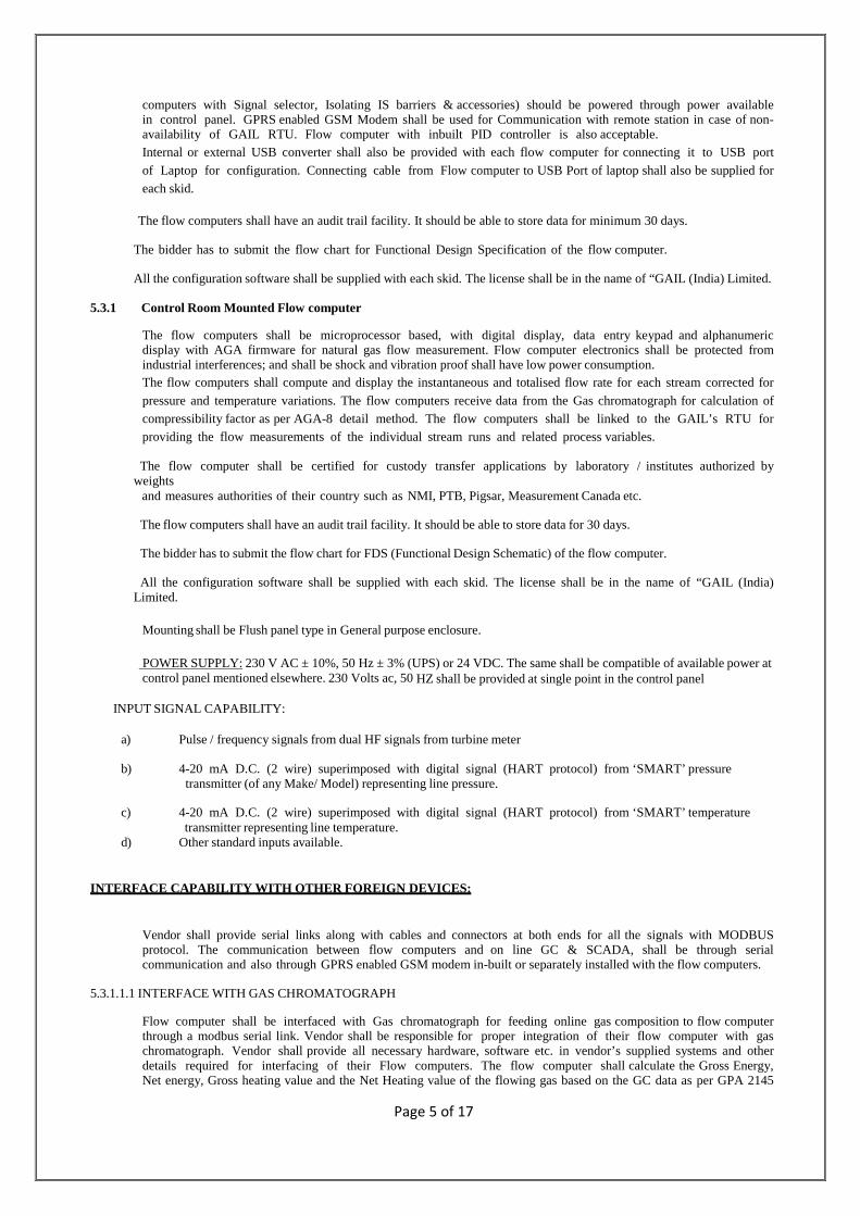
computers with Signal selector, Isolating IS barriers & accessories) should be powered through power available in control panel. GPRS enabled GSM Modem shall be used for Communication with remote station in case of non-availability of GAIL RTU. Flow computer with inbuilt PID controller is also acceptable. Internal or external USB converter shall also be provided with each flow computer for connecting it to USB port
of Laptop for configuration. Connecting cable from Flow computer to USB Port of laptop shall also be supplied for each skid.
The flow computers shall have an audit trail facility. It should be able to store data for minimum 30 days.
The bidder has to submit the flow chart for Functional Design Specification of the flow computer.
All the configuration software shall be supplied with each skid. The license shall be in the name of “GAIL (India) Limited.
5.3.1 Control Room Mounted Flow computer
The flow computers shall be microprocessor based, with digital display, data entry keypad and alphanumeric display with AGA firmware for natural gas flow measurement. Flow computer electronics shall be protected from industrial interferences; and shall be shock and vibration proof shall have low power consumption. The flow computers shall compute and display the instantaneous and totalised flow rate for each stream corrected for
pressure and temperature variations. The flow computers receive data from the Gas chromatograph for calculation of compressibility factor as per AGA-8 detail method. The flow computers shall be linked to the GAIL’s RTU for providing the flow measurements of the individual stream runs and related process variables.
The flow computer shall be certified for custody transfer applications by laboratory / institutes authorized by weights and measures authorities of their country such as NMI, PTB, Pigsar, Measurement Canada etc.
The flow computers shall have an audit trail facility. It should be able to store data for 30 days.
The bidder has to submit the flow chart for FDS (Functional Design Schematic) of the flow computer.
All the configuration software shall be supplied with each skid. The license shall be in the name of “GAIL (India) Limited.
Mounting shall be Flush panel type in General purpose enclosure.
POWER SUPPLY: 230 V AC ± 10%, 50 Hz ± 3% (UPS) or 24 VDC. The same shall be compatible of available power at control panel mentioned elsewhere. 230 Volts ac, 50 HZ shall be provided at single point in the control panel
INPUT SIGNAL CAPABILITY:
a) Pulse / frequency signals from dual HF signals from turbine meter
b) 4-20 mA D.C. (2 wire) superimposed with digital signal (HART protocol) from ‘SMART’ pressure transmitter (of any Make/ Model) representing line pressure.
c) 4-20 mA D.C. (2 wire) superimposed with digital signal (HART protocol) from ‘SMART’ temperature transmitter representing line temperature. d) Other standard inputs available.
INTERFACE CAPABILITY WITH OTHER FOREIGN DEVICES:
Vendor shall provide serial links along with cables and connectors at both ends for all the signals with MODBUS protocol. The communication between flow computers and on line GC & SCADA, shall be through serial communication and also through GPRS enabled GSM modem in-built or separately installed with the flow computers.
5.3.1.1.1 INTERFACE WITH GAS CHROMATOGRAPH
Flow computer shall be interfaced with Gas chromatograph for feeding online gas composition to flow computer through a modbus serial link. Vendor shall be responsible for proper integration of their flow computer with gas chromatograph. Vendor shall provide all necessary hardware, software etc. in vendor’s supplied systems and other details required for interfacing of their Flow computers. The flow computer shall calculate the Gross Energy, Net energy, Gross heating value and the Net Heating value of the flowing gas based on the GC data as per GPA 2145
Page 6 of 17
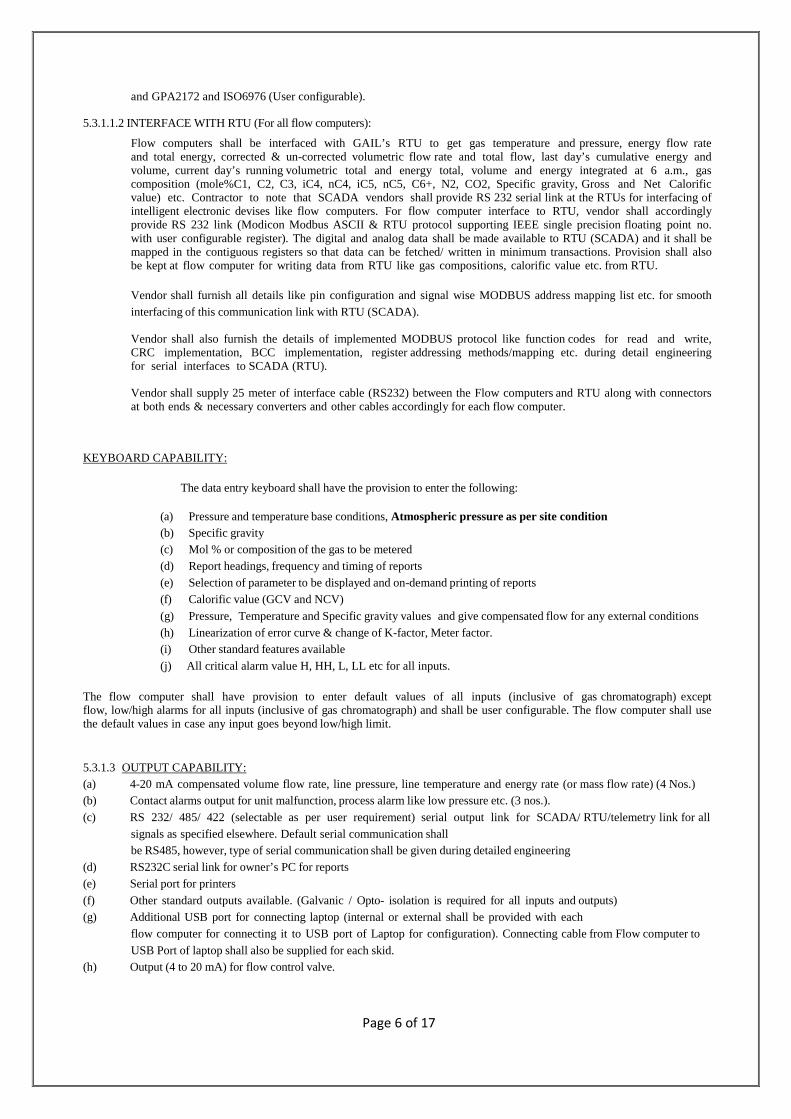
and GPA2172 and ISO6976 (User configurable).
5.3.1.1.2 INTERFACE WITH RTU (For all flow computers):
Flow computers shall be interfaced with GAIL’s RTU to get gas temperature and pressure, energy flow rate and total energy, corrected & un-corrected volumetric flow rate and total flow, last day’s cumulative energy and volume, current day’s running volumetric total and energy total, volume and energy integrated at 6 a.m., gas composition (mole%C1, C2, C3, iC4, nC4, iC5, nC5, C6+, N2, CO2, Specific gravity, Gross and Net Calorific value) etc. Contractor to note that SCADA vendors shall provide RS 232 serial link at the RTUs for interfacing of intelligent electronic devises like flow computers. For flow computer interface to RTU, vendor shall accordingly provide RS 232 link (Modicon Modbus ASCII & RTU protocol supporting IEEE single precision floating point no. with user configurable register). The digital and analog data shall be made available to RTU (SCADA) and it shall be mapped in the contiguous registers so that data can be fetched/ written in minimum transactions. Provision shall also be kept at flow computer for writing data from RTU like gas compositions, calorific value etc. from RTU.
Vendor shall furnish all details like pin configuration and signal wise MODBUS address mapping list etc. for smooth interfacing of this communication link with RTU (SCADA).
Vendor shall also furnish the details of implemented MODBUS protocol like function codes for read and write, CRC implementation, BCC implementation, register addressing methods/mapping etc. during detail engineering for serial interfaces to SCADA (RTU).
Vendor shall supply 25 meter of interface cable (RS232) between the Flow computers and RTU along with connectors at both ends & necessary converters and other cables accordingly for each flow computer.
KEYBOARD CAPABILITY:
The data entry keyboard shall have the provision to enter the following:
(a) Pressure and temperature base conditions, Atmospheric pressure as per site condition (b) Specific gravity (c) Mol % or composition of the gas to be metered (d) Report headings, frequency and timing of reports (e) Selection of parameter to be displayed and on-demand printing of reports (f) Calorific value (GCV and NCV)
(g) Pressure, Temperature and Specific gravity values and give compensated flow for any external conditions (h) Linearization of error curve & change of K-factor, Meter factor. (i) Other standard features available
(j) All critical alarm value H, HH, L, LL etc for all inputs.
The flow computer shall have provision to enter default values of all inputs (inclusive of gas chromatograph) except flow, low/high alarms for all inputs (inclusive of gas chromatograph) and shall be user configurable. The flow computer shall use the default values in case any input goes beyond low/high limit.
5.3.1.3 OUTPUT CAPABILITY: (a) 4-20 mA compensated volume flow rate, line pressure, line temperature and energy rate (or mass flow rate) (4 Nos.) (b) Contact alarms output for unit malfunction, process alarm like low pressure etc. (3 nos.).
(c) RS 232/ 485/ 422 (selectable as per user requirement) serial output link for SCADA/ RTU/telemetry link for all signals as specified elsewhere. Default serial communication shall be RS485, however, type of serial communication shall be given during detailed engineering
(d) RS232C serial link for owner’s PC for reports (e) Serial port for printers
(f) Other standard outputs available. (Galvanic / Opto- isolation is required for all inputs and outputs) (g) Additional USB port for connecting laptop (internal or external shall be provided with each
flow computer for connecting it to USB port of Laptop for configuration). Connecting cable from Flow computer to
USB Port of laptop shall also be supplied for each skid. (h) Output (4 to 20 mA) for flow control valve.

Page 7 of 17
5.3.1.4 COMPUTATIONAL CAPABILITY :
(a) Volume flow rate at standard, normal or operator specified base conditions (Sm3/hr). Initially configured at Base pressure :1.033227 kg/cm2 abs, Base temp : 15.556 °C)
(b) PID algorithm for Flow control. (c) Integrated corrected volume in SCM (d) Energy flow rate and integrated energy (user configurable in MCal, MJ & MMBTU).
(e) Heating value calculation as per ISO-6976/GPA2145/GPA2172 (User configurable). Initially configured as per GPA 2145 / 2172.
(f) Linearization of error flow curve.
(g) Generation of standard and user defined reports at printer. All reports shall be user configurable. (h) Calculation of compressibility factor as per AGA-8 detail method / AGA-8 Gross1/ Gross2 method (user selectable). (i) Previous day’s flow / energy (i.e. yesterday’s Base time total volume / energy to today’s Base time total volume /
energy) & current running total for the day (i.e. volume tantalizer/ integrator value at Base time from first day) to be stored in a separate location (register) and base time shall be user configurable.
(j) Today’s accumulated flow /energy (running total since Base time to current time) and base time shall be user
configurable. (k) Generation of reports for totalised volume & energy at daily, weekly, fortnightly & monthly intervals, flow rate,
pressure, temperature, Uncorrected Flow/ DP, compressibility factor, alarms etc. shall be user configurable.
All the above data shall also be made available by vendor in the serial links to RTU.
5.3.1.5 STANDATRDS USED :
For the above, applicable standards are: (a) AGA report 7 for flow rate and total flow for all tags of Flow meter.
(b) AGA-8 detailed characterization method to determine density, compressibility, super compressibility factor etc. for
flow computers (c) AGA Report 5/GPA 2145-GPA2172 / ISO6976 (user configurable) for energy rate and integrated energy.
5.3.1.6 ENGINEERING UNITS (User Configurable):
Corrected Volume flow rate -Sm3/hr, Mass - kg/hr, Pressure - kg/cm2g, Energy – MMBTU / MCal / MJ/ (user selectable), Temperature - °C, Primarily the unit of measurement for Pressure, Temperature, total energy and Energy flow rates shall be Kg/Cm2g, Deg. C, MCal / MMBTU (user selectable) and Mcal/Hr or MMBTU/hr (User selectable) respectively.
5.3.1.7 MEMORY TYPE: Non volatile
5.3.1.8 A/D AND D/A CONVERTORS:
Calculation accuracy shall be better than ± 0.05% of full scale including linearity, hysterisis, repeatability and resolution. Accuracy for analogue inputs to be minimum 0.075% and for analogue outputs accuracy shall be minimum 0.1%.
5.3.1.9 SCAN PROCESSING TIME:
a) The interval between computer readings of Process variables shall not exceed 1 sec
b) The interval between each cycle for computation of instantaneous flow rate and totalized flow shall be less
than 1 sec.
c) Algorithm and rounding off error for computation shall be with in ±0.001% of computed value
5.3.1.10 SECURITY:
3-Level password protection should be a standard feature in Flow computer.

Page 8 of 17
5.3.1.11 DISPLAY CAPABILITY: The flow computer shall have the capability to display the following parameters:
Uncompensated volume flow rate, Compensated volume flow rate, Integrated volume (corrected and not corrected), Mass flow rate, Integrated mass, Density/Specific gravity, Pressure, Temperature, Energy rate & total energy, Complete gas composition, Calculated parameters (compressibility factor etc.), Current accumulation, previous day accumulation, Data entry, Error codes, Selected parameter codes, Alarms (process and systems) including diagnostic message, Engg. units as per selected parameter, Other standard displays available, Custody transfer flow computers shall have audit trail, All the above data shall also be made available by vendor in the serial links to RTU.
5.3.1.12 DISPLAY TYPE: Alphanumeric LCD display
5.3.1.13 DIAGNOSTICS:
Flow computers shall have elaborate and sufficient on-line diagnostics to ascertain accurate and proper functioning of the flow computer. Results of diagnostics/checking shall be displayed. Provision for high and low limit check for each input, sensor break, saturation and alarms shall be provided.
5.3.1.14 Flow Computer Validation Software:
Supplier to provide one licensed Software in the name of Client for authenticating the algorithm written in the Flow Computers as per AGA-7/ 9 (as applicable).
General Remarks:
a) The software for Configuration of flow computer, Audit trail and history retrieval from flow computer shall be supplied by bidder.
b) Master/ Slave configuration should be possible in Flow Computer for Serial communication with GAIL’s GC. Sufficient output ports shall be envisaged to establish communication with 2 sets of Flow computers installed at different locations.
c) The Flow computer should reject the GC data during GC calibration / Calibration Check and should use the previous data for calculation.
f) Audit Trail feature should display detailed description, old and new value of parameter changed along with time stamp.
g) The Flow computers should accept GC data through GPRS enabled GSM Modem or SCADA or Serial link (user selectable). Spare port shall be provided in Flow computer for SCADA communication via RS 422/ 485/ 232 (user selectable).
h) Alarm should appear when there is Loss of signal/ HF Pulse from Turbine meter. i) Where ever possible, HF pulse shall be used for Turbine meters and RPD meters.
5.4 Control Panels
5.4.1 The prefabricated metering control panels shall be supplied and tested with all items/ instruments mounted and all wiring installed requiring only connection of field wiring to terminal blocks provided for this purpose and inter-panel wiring in order to commission the panels. Metering control panel shall be free-standing type.
5.4.2 Vendor shall be responsible for manufacture and supply of all necessary hardware and software to meet the
functional requirements including Factory Testing (FAT) and Acceptance of the system.
5.4.3 Power supply of 230/ 110 V AC ± 10%, 50 Hz ± 3% UPS (as per the availability of power at site) shall be made available by GAIL to vendor at a single point in the Metering control panel being supplied by vendor. Further distribution to all the instruments, accessories in panel and field instruments at Gas metering skid with all items like MCBs, Bus Bars etc. shall be in vendor’s scope. All the equipments by vendor shall be suitable for the specified voltage variation. Vendor has to made provision in the panel for accepting power supply from electrical feeder and install suitable redundant power supplies for their usage based on suitable load calculation of the entire supplied system.
5.4.4 Vendor shall furnish power consumption details for control panel, each type of power supply mentioned above.
5.4.5 Vendor shall be fully responsible for the manufacture in respect of proper design, quality workmanship and
operation of all the equipment, accessories, etc. supplied by the vendor for the Metering Control panel.
5.4.6 It shall be obligatory on the part of vendor to modify and / or replace any hardware and modify the operating,

Page 9 of 17
application and diagnostic software free of cost, in case any malfunction is revealed even during on line operation after taking over by the owner within the warranty period.
5.4.7 Factory Acceptance Test and Calibration of all items shall be carried out by the vendor and fully compliant reports
shall be furnished to Owner meeting the complete requirements. Owner can witness any or all items testing in stages during manufacture and/or at final stage before shipment at the discretion of Owner.
5.4.8 Vendor shall provide all required Commissioning Spares for the package and shall provide a list of these spares.
If however any additional spare is consumed during erection and commissioning the same shall be provided free of cost by the bidder.
5.4.9 Vendor shall provide hot redundant Power supply in control panel. All the hubs/ routers/ switches/ converter shall also be redundant.
5.4.10 The control panel shall also have hooter for generation of Audible alarm (system generated alarms, process alarm,
Flow computer / GC alarms, operator assigned alarm, Metering supervisory system alarms) and push button shall be provided for Test/ Acknowledge/ accept/ reset of Alarm. Selector switch shall be provide in the panel for selection of operating flow computer (which is in line) for PID control (Flow control) through FCV installed in field. The PID signal for Flow control (through FCV) shall be sent through operating Flow computer.
5.5 KOD SYSTEM AND FILTRATION SYSTEM
5.5.1 Suitably sizing for designed process parameters a knock out drum 100% capacity with level gauges, PSV, vent and drain arrangement etc as per drawings and specification given in tender. It shall have inlet and Outlet ball valves. Suitable bypass arrangement for Inlet ball valve to be provided as per tender requirement. All the design calculations need to be submitted along with the bid documents.
The filtration system shall consist of one no V E R T IC A L filtration systems. The filter cover for each filter shall be provided with Davit arm for ease of maintenance. QOEC with Davit arm is required for Shell/ cover Flange above 10” dia. For Filters with Shell cover / Flange upto 10”, Blind Flange with Davit arm is acceptable. The design of filter shall be such that, the liquid/condensate can be drained in pressurized condition. All drains and vents shall have one ball valve & one plug valve. Fire case PSV of suitable capacity shall be installed in each filter. The filtration capacity shall be 5 microns for gas filter. For Inlet mainline Ball valves (for the filter) shall be provided with equalizing (Block and bleed) arrangements. The withstanding capacity of the filter cartridge shall be more than 1 Kg/cm2. However the DP across the filter in operating condition shall not exceed more than 0.1 kg/cm2. The filtration capacity shall be suitable for 100% of maximum flow possible through selected nozzle.
5.5.2 The Inlet and Outlet nozzles of individual streams of Filtration system shall be designed considering velocity
limit of 20 m/s with rated (max.) flow at operating condition (at minimum operating pressure and max. operating temperature). However the capacity of the filtration system shall be considered as maximum flow possible through selected nozzle (at minimum operating pressure and max. operating temperature) subjected to velocity limit of 20 meters /sec and filtration elements surface area shall be minimum 8 times the cross sectional area of the selected inlet/ outlet nozzles.
5.5.3 The gas filtration system shall be used to remove dust particles up to 5 micron and to remove condensate if any. Fire
case Pressure safety Valves (PSV) shall also be provided on each filter. Each filter stream shall have inlet and Outlet ball valves. Suitable bypass arrangement for Inlet ball valve to be provided as per tender requirement.
Please refer standard technical specifications attached elsewhere for further details. PWHT (Post weld Heat Treatment) shall
be as per ASME code requirement.
5.6 FIELD TRANSMITTERS (Custody & non-custody type)
5.6.1 Field Transmitters shall interface with field mounted Solar powered flow computers / control room mounted flow
computers. These field transmitters can be supplied with/ without HART. For field mounted flow computers. For metering skids with Control room mounted Flow computers, bidder shall supply SMART type transmitters (HART) as per vendor list..
5.6.2 Accuracy of all the pressure transmitters (at the skid inlet, Metering system etc) shall be 0.04% of span or
better (with Turn down ratio 1:5). Accuracy of differential pressure transmitters shall be ± 0.075% of span or better. This accuracy includes the combined effect of zero stability, linearity, hysteresis and repeatability. Transmitter element material shall be minimum AISI SS 316. The Accuracy of Temp. Transmitter shall be 0.15 % of span.
5.6.3 All smart transmitters shall have range-ability of 1:100 having integral intrinsic safe local LCD Display.

Page 10 of 17
5.6.4 Static pressure rating for all the transmitters (PT, DPT) should be of the order of minimum 100
Kg/cm²g for all applications in general. However bidder must ensure that static pressure shall not be less
than 1.3 times of maximum operating pressure for ranges above than 1 kg/cm²g.
5.6.5 The transmitters shall be enabled to HART protocol (only for transmitters connected to Control room mounted Flow computers / indicators). Transmitters communicating with Field mounted Solar powered Flow computers can be low power. For Solar Powered Field mounted Flow computers, Metering PT can also be in built/ integral (impulse line for Pressure directly connected to Flow computer).
5.6.6 All The transmitters envisaged for skid with Field mounted Flow computer (with Solar panel) shall be Low power.
5.7 TEMPERATURE TRANSMITTERS with CLASS ”A” 4-wire RTD (PT-100) Element.
5.7.1 RTD sheath material shall normally be SS 316 as a minimum and RTD shall be Class “A” type with 4 wire system. The gauge head of the Temperature elements (RTD's) shall be 80 mm, as a minimum to ensure maintenance ease.
5.7.2 For temperature transmitters connected to Control room mounted flow computers, the temperature transmitters shall be smart type and shall provide ‘HART’ output. Temperature Transmitters with dual compartment Housing (for termination and display) shall be supplied for maintenance ease. Temperature Transmitters with dual compartment Housing (for termination and display) shall be supplied for maintenance ease. For interface with field mounted solar powered flow computers, temperature transmitters without HART are also acceptable.
5.7.3 Bidder to note that all thermo-wells except surface temperature instruments shall be of flanged type
only.
5.7.4 The RTD shall be Class ”A” type-4 wire PT-100. The RTD & thermo-well shall be designed in such a way that the insertion length in side the pipe shall be more than 60%.
5.8 RECEIVER INSTRUMENTS
5.8.1 Other than custody transfer transmitters, the indication/ display like Filter DP, pressure & Temperature at Inlet
& outlet etc. shall be provided in the control panel.
5.8.2 Indication for slam-shut valves & Metering Ball valve shall also be provided in Flow computer for all Metering skids and also additionally in Control panel based metering skids (for SOR item 6 and 10).
5.9 ISOLATING BARRIERS
In general, intrinsically safe philosophy shall be followed for all transmitters. Bidder to note that external barriers shall be selected based on entity concept.
Typically barrier selection must be made based on the following:
i) Analog Inputs (4-20 mA): Series 5000 of MTL/ P&F KFD series/ Eqv.
ii) Analog Outputs (4-20 mA): Series 5000 of MTL/P&F KFD series/ Eqv. iii) Proximity Inputs: Series 5000 of MTL/ P&F KFD series/Eqv.
5.10 CABLES
5.10.1 All cables shall have PVC insulated primary insulation of 85DC PVC as per IS-5831 Type C/ IEC 502. Inner
and outer jacket shall be made of extruded flame retardant 90 deg C PVC to IS-5831 Type ST-2 / IEC 502. Oxygen index of PVC shall be over 30% and temperature index shall be over 250 deg C.
All cables shall be armoured and fire retardant as per standard IEC 332-3 Part 3 Cat. A. Fire resistance cables
whenever specified shall be as per IEC 331 Cat. A.
Signals cables shall be Type I for single pair and Type IV for multi-pair armoured cables. For cable specification,
refer enclosed standard specification elsewhere. All the cables glands (Field/ JB end), shall be of nickel-plated brass and These glands shall be double compression type suitable for armoured cables. Flame proof Glands wherever required shall be supplied with Ex-d certification.
5.11 JUNCTION BOXES
5.11.1 Bidder shall supply junction boxes as per the cables selected, wherever required. These shall be of die cast
Page 11 of 17
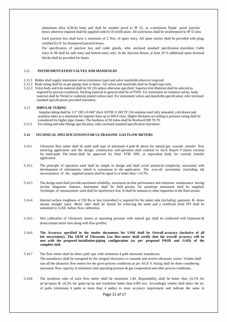
aluminium alloy (LM-6) body and shall be weather proof to IP 55, as a minimum. Flame proof junction boxes wherever required shall be supplied with Ex’d’certification. All such boxes shall be weatherproof to IP 55 also.
Each junction box shall have a minimum of 2 Nos. of spare entry. All spare entries shall be provided with plugs
certified Ex’d’ for flameproof junction boxes.
For specification of junction box and cable glands, refer enclosed standard specification elsewhere. Cable
entry in JB shall be side entry and bottom entry only. In the Junction Boxes, at least 20 % additional spare terminal
blocks shall be provided for future.
5.12 INSTRUMENTATION VALVES AND MANIFOLDS
5.12.1 Bidder shall supply instrument valves (miniature type) and valve manifolds wherever required. 5.12.2 Body rating shall be as per piping class or better. All valves and manifolds shall be forged type only. 5.12.3 Valve body and trim material shall be SS 316 unless otherwise specified. Superior trim Material shall be selected as
required by process conditions. Packing material in general shall be of PTFE. For instrument air isolation valves, body material shall be Nickel or cadmium plated carbon steel. For instrument valves and manifolds specification, refer enclosed standard specifications provided elsewhere.
5.13 IMPULSE TUBING
Impulse tubing shall be 1/2" OD x 0.049" thick ASTM A 269 TP 316 stainless steel fully annealed, cold drawn and seamless tubes as a minimum for impulse lines up to 600 # class. Higher thickness according to pressure rating shall be considered for higher pipe classes. The hardness of SS tubes shall be Rockwell RB 70-79.
5.13.1 For tubing and tube fittings specification, refer enclosed standard specification elsewhere.
5.14 TECHNICAL SPECIFICATIONS FOR ULTRASONIC GAS FLOW M ETERS
5.14.1 Ultrasonic flow meter shall be multi path type of minimum 4 path & above for natural gas custody transfer flow metering application and the design, construction and operation shall conform to AGA Report 9 (latest version) for multi-path. The meter shall be approved by Nmi/ PTB/ NPL or equivalent body for custody transfer application.
5.14.2 The principle of operation used shall be simple in design and shall avoid analytical complexity associated with
development of information, which is extraneous to the application. The over-all uncertainty (including lab uncertainties) of the supplied system shall be equal to or better than +/-0.3%.
5.14.3 The design used shall provide maximum reliability, maximum on-line performance and minimum maintenance having
on-line diagnostic features. Instrument shall be field proven. No prototype instrument shall be supplied. Technique of measurement used shall be interference free. It shall be immune to other impurities in the fluid stream.
5.14.4 Internal surface roughness of 250 Ra or less (smoother) is required for the meter tube (including upstream & down
stream straight runs). Meter tube shall be honed for achieving the same and a certificate from TPI shall be submitted to GAIL before flow calibration.
5.14.5 Wet calibration of Ultrasonic meters at operating pressure with natural gas shall be conducted with Upstream & down stream meter runs along with flow profiler.
5.14.6 The Accuracy specified in the tender documents for USM shall be Overall accuracy (inclusive of all
lab uncertainty). The OEM of Ultrasonic Gas flow meter shall certify that the overall accuracy will be met with the proposed installation-piping configuration (as per proposed P&ID and GAD) of the complete skid.
5.14.7 The flow meter shall be direct path type with minimum 4 path ultrasonic transducers.
The transducers shall be energized by the integral electronics to transmit and receive ultrasonic waves. Vendor shall
size all the ultrasonic flow meters for the given process conditions as per AGA 9. Sizing shall be done considering maximum flow capacity at minimum inlet operating pressure & gas composition and other process conditions.
5.14.8 The turndown ratio of each flow meter shall be minimum 1:40. Repeatability shall be better than ±0.1% for qt<qi<qmax & ±0.2% for qmin<qi<qt and resolution better than 0.001 m/s. Accordingly vendor shall select the no. of paths (minimum 4 paths or more than 4 paths) to meet accuracy requirement and indicate the same in

Page 12 of 17
calculations / back-up literature.
5.14.9 The meter shall be provided with pressure tap to measure the static pressure in the meter.
5.14.10 The meter body shall be made of carbon steel as per data sheets (ASTM A 216 GR. WCB or better). All flanges
shall be weld neck, raised face and shall meet ANSI B 16.5. The ultrasonic metering system shall be provided
with full diagnostics and customer user interface. 5.14.11 It shall be possible to replace or relocate transducers without a change in meter performance. After an
exchange of transducers and a possible change of the associated software constants, the resulting shift in the meter's performance should not be more than the allowable repeatability of the meter. In addition, the maximum error and the maximum peak-to-peak error as detailed in AGA-9 shall not be exceeded.
5.14.12 The vendor shall comprehensively advise the impact of transducer failure on the performance and accuracy of
the USM. Vendor shall confirm that the measurement will not degrade by more than ± 0.05% in case of loss of one path.
5.14.13 The meter design shall have the facility to remove / replace the transducers in situ under line operating condition. Failure or removal of one pair of transducers shall not cause the meter to lose all measurement function. Failure of any path shall generate an alarm identifying the affected path. Also transducers ports shall be designed in a way to reduce the possibility of liquid or solid accumulation.
5.14.14 Area classification shall be IEC Zone-1, Gas Gr. II A & IIB, and Temperature Class T3.
All electrical instruments in the field shall be suitable for the specified area classification and certified by a statutory body such as FM, UL, CENELEC, BASEEFA, and PTB etc. The transducers shall be intrinsically safe certified suitable for the specified area classification and weather proof to IP65/NEMA-4 and vendor shall supply necessary isolating barriers between the transducers and preamplifier/transmitter. However the transducer/sensor housing can be flameproof (EEx d) certified suitable for the specified area classification instead of intrinsically safe.
5.14.15 Overall pressure drops across the meter assembly including meter runs shall be kept minimum. Pressure drop calculation across the meter shall be furnished. Ultrasonic meters shall be rated for the maximum design pressure as indicated in the data sheets.
5.14.16 Ultrasonic flow meter spool inside diameter to meet the specified I.D as per AGA. Internal surface roughness shall be as specified elsewhere.
5.14.17 All ultrasonic flow meters shall be supplied with upstream meter run with flow conditioner/ profiler (min.10D
before flow profiler, 10 D between flow profiler and US meter) and downstream meter runs (min.5D). 5.14.18 The Meter body length and bore has to be specified by the US Meter Manufacturer.
The USM bore and the adjacent upstream pipe along with flanges should have the same inside diameter to within 1% of each other. Vendor has to provide document to justify the same duly certified by third party internationally recognized certifying agencies.
5.14.19 External meter body shall be blast cleaned to near white metal as per international standard and primed with inorganic zinc primer (two coats each of 40 micron minimum dry film thickness) and the final coat of epoxy paint of 40- micron dry film thickness.
5.14.20 METER ELECTRONICS:
a) Meter electronics shall include all associated transmitters, pre-amplifiers etc. b) The transmitter unit shall be microprocessor-based electronics suitable for installation in the field under the ambient
condition specified. Meter electronics shall be Weather proof to IP 65/ NEMA 4 and flameproof certified suitable to install in area classification IEC Zone-1, Gas Gr. IIA & IIB, Temp. Class T3 by a statutory body such as FM, UL, CENELEC, BASEEFA, PTB etc.
c) The electronics unit shall preferably be mounted integral on the meter. d) The transmitter shall have extensive diagnostic capability. Self-diagnostic feature should include monitoring the
health of the transducers and signal quality. e) Meter parameters and factors set into the meter electronics shall be retained in non- volatile memory and shall be
secured with password such that un-authorised changes are prohibited. f) Configuration software and firmware shall be provided for skid. The license shall be in the name of “GAIL (India) Ltd”. g) Meter output signals from the meter electronics shall be without flying leads. All the signals from the meter
electronics shall be terminated in a junction box (JB) supplied by the meter vendor and shall be mounted on skid. JB shall be weather proof (WP) to IP 65/NEMA 4 and flameproof certified suitable for the specified area classification.
h) The cable entry sizes between meter electronics and transducers shall be decided by vendor and the WP & flameproof cable glands to be supplied accordingly. Cable entry sizes shall be as per NPT standards.
i) The maximum velocity through the ultrasonic meter shall be less than 20 m/sec. j) Meter electronics shall be capable of multiple output signals as follows: - Pulse outputs to flow computers configurable for flow rate signals.

Page 13 of 17
- RS-485/422 communication port with MODBUS protocol for communicating with the control systems i.e. control room mounted flow computer for meter diagnostics, test and health data.
m) Vendor shall supply the RS 485/422 cables interconnecting serial link cables which shall be armoured along with suitable connectors and converters against each item/ instrument/ tag for communication between flow meter in field and flow computers mounted on metering control panel located at respective control room.
n) The USM shall be connected to the flow computer serially for digital communication and also for frequency pulse signal shall be connected to flow computer for custody transfer flow indication.
o) Facility of any error correction in USM as permitted for custody transfer application shall be provided.
5.14.21 On Line Field Verification:
Speed of Sound comparison should be done in the stream flow computer for the speed of sound measured value from the USM and the speed of sound calculation based on the GC component data as per AGA 10. If the difference between the SOS between the actual and the calculated one is more than the permissible limit then the flow computer shall generate a alarm. Separately, Licensed software shall be provided in name of GAIL for Speed of Sound calculation (as per AGA 10) as mentioned in Clause No 8 of AGA9.
5.14.22 VERIFICATION FOR CUSTODY TRANSFER AND CALIBRATIO N
5.14.22.1 For skids with Ultrasonic Meters; vendor shall provide certification from Calibrating agency/ Laboratory / OEM
of Ultrasonic Gas Flow meter confirming that the meter being calibrated shall work with specified accuracy/ repeatability with the actual gas composition mentioned in the tender documents. Further certificate must mention that the overall accuracy, performance and repeatability as mentioned in the tender shall be met with the proposed installation-piping configuration (as per proposed P&ID and GAD) of the complete skid. (Vendor shall submit the Calculation for overall system uncertainty including all components of the metering system)
5.14.22.2 Each meter shall be “zero calibrated” (“dry calibrated”) with nitrogen. Test results shall be furnished. In the
dry calibration set up, the gas velocity observed on all the acoustic paths shall be zero. The speed of sound of the individual acoustic path in the dry calibration set up shall not exceed ±0.2% of the mean velocity of all the paths
5.14.22.3 Flow calibration with high pressure Natural gas shall be performed for at least seven points (at 2.5%, 5%,
10%, 25%, 50%, 75% and 100% of Qmax.) and error curve shall be obtained. Flow Verification for at least two points shall be done after adjustment/ incorporation of factors obtained through calibration, in the ultrasonic meter Electronics and the same to be recorded in the calibration report, as per AGA-9.
5.14.22.4 Vendor shall carryout performance test and certify the meter in combination with its companion electronics. A
recognized test facility with traceable reference measurements shall be used. Flow test data at 6 points covering the minimum to the maximum flow rate shall be obtained for ascertaining the meter linearity and repeatability with in the specified limits. The pressure for wet calibration of USM shall be close to the average of minimum and maximum metering Pressure.
5.14.22.5 The Ultrasonic meters shall be ‘flow calibrated’ with natural gas and shall have calibration certificate duly
signed by laboratories approved by weights and measures authority of its country of origin or recognized international Institutes like NMI, PTB, Pigsar, Trans Canada Calibrations(TCC) Canada, Measurement Canada, Colorado Engineering Experiment Station Inc.(CEESI) USA etc. Accuracy with wet flow calibration shall be demonstrated within ±0.3% for multi path type under flow conditions in the turndown ratio of 1:10. The meter proving system to be used by vendor shall be traceable to international standards and uncertainty of meter proving system shall be furnished. Gas metering system integration, testing, validation and including third party "wet' calibrations ( for the ultrasonic meters with its associated upstream / downstream meter runs & flow profiler) should be done in flow labs as detailed above.
5.14.22.6 GAIL (INDIA) LTD has also developed wet calibration facility of USM meters with natural gas at HAZIRA. The
bidder can also opt for wet calibration of USM at GAIL Hazira subjected to the condition that the facility is certified for doing wet calibration of USM by recognized international Institutes like NMI, PTB, Pigsar, Trans Canada Calibrations (TCC) Canada, Measurement Canada, Colorado Engineering Experiment Station Inc.(CEESI) USA etc. Accuracy with wet flow calibration shall be demonstrated within ±0.3% for multi path type under flow conditions in the turndown ratio of 1:10. The meter proving system to be used by facility shall be traceable to international standards and uncertainty of meter proving system shall be furnished. Gas metering system integration, testing, validation and including third party "wet' calibrations ( for the ultrasonic meters with its associated upstream / downstream meter runs & flow profiler) should be done in flow labs as detailed above.
In case the bidder opts for wet calibration of USM at GAIL Hazira, it is bidder’s responsibility to coordinate, transport
the USM metering to and fro, get the wet calibration done within the time frame, pay the charges if any etc as per terms and conditions given from GAIL, Hazira facility. Bidder should confirm the same in detail from GAIL Hazira facility before submission of tender and no additional payment shall be given on account of any changes/alteration afterwards.

Page 14 of 17
5.14.23 Calibration report
The results of flow calibration shall be documented in a written report to be supplied to GAIL. For each meter, the report shall include at a minimum the following:
a) Name of Meter Manufacturer b) Model and Serial No. of Meter c) Name and Address of the Calibration facility. d) SPU Firmware revision number e) Date(s) of calibration
f) Name and Designation/ Title of the person(s) conducting calibration
g) Description of calibration procedure
h) Upstream and Down-stream piping configuration including flow profiler, meter runs.
i) Serial nos. of all piping and flow profiler j) Diagnostic report of the software configuration parameters at the time of calibration
k) All calibration data including Flow rates, Pressure, Temperature, Velocities, errors and gas composition
l) A statement of uncertainty for the facility with reference to the method used and date of last verification of
traceability to the recognized national/ International standard.
m) An Identification of Adjustment method applied and adjustment factors used
n) No. of pages in the calibration document o) Typed name below signature(s) of all the people who sign the calibration document.
5.15 CHECK & PAY CONFIGURATION & PROCEDURE for USM Based Me tering Skids:
The following Procedure is applicable for USM based Metering skid having Z- Configuration (for
Meter Verification through PAY-CHECK configuration). This scheme/ configuration shall be implemented in the Supervisory system being provided by the Bidder.
Stream-1 shall be selected in “PAY” mode and Stream-2 can be selected in “CHECK” mode. Both “PAY” and “CHECK” Flow computers (Stream-1 and 2) shall do fiscal metering separately/ independently and update data in the supervisory computer. In “PAY” Flow computer all fiscal totals get incremented. In “CHECK” Flow computer only maintenance totals get incremented. When the User decides to do meter verification and selects the “PAY” and “CHECK” streams at the meter verification window. The stream selected as “CHECK” shall put its Flow computer in “Maintenance mode” automatically by the HMI system and thereby its maintenance mode totals in the Flow computer shall increment, keeping the fiscal totals at the last reading. Once the streams-1 and 2 are selected in “PAY” and “CHECK” mode respectively and the User clicks on the begin button, a
confirmation is required from the user to proceed ahead. Once the user confirms, system prompts to align the Valves
according to PAY-CHECK streams configuration. The Valve alignment procedure during meter verification is
mentioned below. Once User manually aligns the Valves according to PAY-CHECK streams, reconfirmation
is requested from the User that the Valve alignment has been completed. HMI system also verifies the correct valve
alignment by checking valve open / close feedbacks. After User confirmation by clicking Start button, the system captures cumulative UVOL, CVOL, Mass and Energy Totals of “PAY” Flow computers and are stored as Start status. For “CHECK” Flow computer, Maintenance UVOL, CVOL, Mass and Energy Totals are recorded as Start status of “CHECK” Flow computer.
Cumulative Totalisers of “PAY” Flow computer and “CHECK” Flow computer increment till User Clicks on Stop
Button. When verification is stopped, the system displays respective Totalisers for the Flow computers as Stop status
and also calculates the difference between Stop status and Start Status. Percentage difference between “PAY” Flow computer Totalisers and “CHECK” Flow computer Maintenance Totalisers are calculated and displayed as accuracy indication of Meter under Test. After Meter verification has been stopped, User can either press Yes Button to continue with the meter verification or else press NO Button to move ahead in the sequence and then align the valves as per the procedure mentioned below. After User clicks “RESET” Button, and confirms the “Reset” then the Flow computer status of “CHECK” stream is changed from Check to Offline, resets all other parameters like difference and accuracy readings.
This completes the Meter Verification.
a. Valve Alignment procedure during meter verification:

Page 15 of 17
Correct sequence of Valve operation is as follows when “PAY” stream is to be verified using “CHECK” Stream.
1. Open “PAY” stream Inlet Valve. 2. Open Crossover Valve(s) 3. Ensure closure of “CHECK” Stream Inlet valve 4. Open Outlet valve of “CHECK” Stream 5. Close “PAY” stream Outlet Valve.
b. Valve Re-alignment procedure after completion of meter verification:
1. Close Cross over Valve(s) 2. Open “PAY” stream Outlet Valve 3. Close Outlet valve of “CHECK” Stream
5.16 METERING SUPERVISORY SYSTEM
All the process parameters of the skid including flow computer & GC data shall be provided in the metering supervisory system, which shall be the Human Machine Interface Station Computer. The operating system of HMI of the Metering Supervisory System shall be window based. The computer system for the supervisory control system shall be industrial type IBM compatible, suitable for continuous operation in the non-air-condition environment. It will be mounted in the control panel. The system shall be supplied complete with keyboard, 17” LCD Monitor, pointing device, hub, signal converter (RS 485-232 or vice-versa), all accessories, cables, Connectors and HP laser Printer with 1000 A4 size plain white paper. Licensed version (in name of “GAIL”) of all the required software to be installed and supplied with the supervisory system. The supervisory system shall be capable to provide read only data to consumer through serial communication and shall be web enabled. The computer shall be capable for generating Reports, Audit trail, current and historical trend for the process variables. It should have facility of Process data, Alarm manager, Diagnostic Manager (Automatic Verification), Configuration log, Audit trail etc.
Online validation software with license shall be supplied and shall be installed in HMI. Validation software shall be compatible with supplied front end software of HMI and shall be suitable for the application.
Metering supervisory system shall be designed to work in non air conditioned environment and shall be panel mounted (supplied by bidder). It shall be suitable for environmental conditions mentioned elsewhere.
The computer of metering supervisory system shall have hardware with latest configuration and shall have minimum specification of 1GHZ Pentium IV Processor with high resolution SVGA Monitor with 17” LCD screen, 512 MB RAM, R/W CD ROM Drive. The monitor shall have high speed refresh rates, 1280 X 1024 pixels and 256 basic distinct colours. The monitor shall be anti- glare, anti-reflective and anti-static. No obsolete hardware shall be supplied.
The HMI software shall be a internationally renowned standard Software like wonderware, IFIX, Intellution, cimplicity, licensed in the name of GAIL (INDIA) Ltd. The supplied software shall be Full version (not the run time version) so that it can be upgraded and future changes can be made, if required. All the hardware required to meet the functionality shall be installed in a Control panel. HMI software shall be configure for monitoring of supplied system flow computer as well as the existing two Daniel make S600 flow computers new LEL system and existing GC (Daniel make 570 series 2350A controller) . It is bidder’s responsibility and scope to configure all the facilities in HMI software for all three flow computers and GC. Bidder should select the I/O CAPACITY of supplied HMI software so that all three flow computers, LEL system and existing GC can be monitored through the same.
Metering supervisory system as a minimum, shall contain the following:
a) Display of all the major equipments (indicated in P&ID) along with its Status (BV open/close indication, SSV open/ close status indication etc.) indication in dynamic body colour (depending on change in the status, body colour of equipments shall change).
b) Display of all analog parameter-values (like Inlet PT, Inlet TT, Metering PTs, Meter TTs, DPTs, Corrected Volumetric Flow rates, Uncorrected Volumetric Flow rates, GC–DATA (composition), Specific Gravity, SOS-USM-Paths(path-1, Path-2.---, Path-x), SOS-FCs, GCV-FC, GCV, NCV, Compressibility factors, Energy flow rate, mass flow rate, Total energy flow, total Mass flow, Total Volumetric Flow etc. Display of GC parameters (GC- DATA), FC-DATA(FC-configuration Parameters, base conditions, Keypad values, Alarm values, Atmospheric pressure, Error curve, Meter factor, K-factor etc.) shall also be provided.
c) The screenshots shall also have feature of display of current/ historical trends, History, Audit trail, Reports etc.

Page 16 of 17
LOG Reports (Shift/ Daily/ weekly/ Monthly/ fortnightly Reports) of Metering Supervisory system shall include the following
(as a minimum):
Shift-wise Log Report (for Morning (A) shift, Evening (B) shift and Night (C) shift) shall be generated at pre-defined 8-hour time interval (say at 06:00 hrs, 14:00 hrs and 22:00 hrs). The report header shall display: Report type: Shift-wise; Name of shift: Morning(A)/ Evening(B)/ Night shift(C) (which ever applicable) Date and Time of Report; Report from(---:00 hr.) to(---:00 hr) The parameters (Hourly Average value of parameters) to be displayed shall be for the following parameters : Inlet PT, Inlet TT, DPTs, Metering PTs, Metering TTs, Uncorrected volumetric flow rates, Corrected Volumetric Flow Rates, Mass flow rates, Energy Flow rates, NCV, GCV, Specific Gravity, Compressibility factors(base/ line), GC-Data (Gas Composition in %), SOS readings from USM, SOS calculated by FC, Heating values calculated by Flow Computers etc. Parameter name, Parameter description, Unit of Measurement of various parameters should be provided in the Shift Log report.
Daily Log Report shall be generated at pre-defined 24-hour time interval (say at 06:00 hrs). The report header shall display : Report type: Daily Log; (which ever applicable) Date and Time of taking Report; Report from(---:00 hr. on --/--/--) to (---:00 hr on --/--/--). In the static Fields of Daily Log report, column-wise display of Parameter name, Parameter description and
Unit of Measurement of various parameters should be provided (Column-A shall display parameter-name, Column–
B shall display parameter Description and Column–C shall display Unit of measurement).
The Daily (24 hourly) Log Report shall contain at least 4 columns for display of Parameter-values. The contents of the first 3 columns shall be 8-hourly values (taken at the end of each shift mentioned above) for each Parameters/
Totalized values. For example, 1st column shall display 8-hourly average reading for each parameter from 06:00
hrs. to 14:00 hrs of previous day. The 2nd column shall display 8-hourly average reading of parameter from 14:00
hrs. to 22:00 hrs of previous day. 3rd column shall display 8-hourly average of parameter from 22:00 hrs. of
previous day to 06:00 hrs of current day. The 4th Column shall display Daily average value (average of the last 24 hrs reading, reckoned from 06:00 hrs of previous date to 06:00 hrs. of current date)/ Accumulated value during last 24 hrs. The parameters to be displayed shall be for Inlet PT, Inlet TT, DPTs, Metering PTs, Metering TTs, Uncorrected vol. flow rates, Corrected Volumetric Flow Rates, Mass flow rates, Energy Flow rates, NCV, GCV, Specific Gravity, Total Uncorrected Volumetric Flow (during last 24 hrs), Total Corrected Volumetric Flow (during last 24 hrs), Total Mass Flow (during last 24 hrs), Total Energy Flow (during last 24 hrs), etc.
Fortnightly/ Monthly report shall display daily average figures (24-hourly average values) of various parameters mentioned above for the last 15 days/ last month. These reports shall be automatically generated at pre-defined 15/ monthly interval (say on 01.04.2010, 16.04.2010 ------ at 06:05 hrs). The Header of Fortnightly/ Monthly Reports shall be: Fortnightly Report/ Monthly Report (as applicable) with date and time of report and date and time of values displayed (from 06:00 hrs of --/--/-- to 06:00 hrs of --/--/--).
5.17 Supply of Gas Chromatograph system in this tender is not envisaged but the existing online GC is to be used for
interfacing with supplied flow computer for online GC data available all the time. The existing GC is of Daniel make- 570 series and GC controller model is 2350A. A spare port Rs232/485 is already available in existing GC and it is bildder’s responsibility to configure and communicate the supplied flow computer for online GC data updation. Bidder’s scope shall also consists of all the hardware like converters, cables etc
5.19 HYDROCARBON (LEL) DETECTORS
5.19.1 Minimum 6 nos. of Hydrocarbon (LEL) detectors per skid shall be used to monitor hydrocarbon gas leakages
from the equipments (like Filtration, PRS, metering system etc), valves, piping etc. 5.19.2 LEL detectors shall be provided for each skid. The isolated 4-20mA analog output from each detector shall be
taken to LEL Monitors/ controllers (to be mounted on Metering Control Panel.
5.19.3 Construction and performance of hydrocarbon gas detection system shall be as per BS EN-50054 and 50057.
5.19.4 Basic criteria for deciding location shall be prevailing wind direction and gas densities.

Page 17 of 17
5.19.5 The infra-red type LEL detectors shall be used and shall be dual beam, dual wavelength type.
5.19.6 LEL detectors/transmitters shall be microprocessor based and shall be immune to RF and EM interference.
5.19.7 LEL detectors shall be immune to catalytic poisons and sunlight
5.19.8 Heated optics shall be provided in the LEL detectors to avoid condensation on the window/mirror in the detectors.
5.19.9 Vendor to indicate drift in the calibration of the LEL detectors.
5.19.10 All LEL detectors/transmitters shall be supplied pre-calibrated by the vendor either with the gas to be sensed or by applying cross sensitivity factors to achieve an installed accuracy of ± 2% LEL at site.
5.19.11 All calibration equipment required for site calibration of the detectors including calibration kit with S/W and
special connector, calibration gases (for minimum 6 months use), gas cylinders, self regulating valves, pressure gauges, hose, interconnection tubing, fitting etc., shall be supplied by the vendor.
5.19.12 Any special tool required for the maintenance of the system/ detector head shall be supplied by the vendor. The
maintenance of any detector head/module should not necessitate shutdown of total/partial detection system except those that are being maintained.
5.19.13 Lamps in the infra-red detectors shall be replaceable type. Lamp life shall be minimum 5 years or more.
5.19.14 Infra-red detectors shall be compensated for lamp intensity variation due to dust, variation in humidity etc. All
the supplied LEL detectors/ transmitters shall be weather proof to NEMA 4 or IP 55. 5.19.15 Vendor to furnish calibration procedure for the LEL detectors/transmitters.
5.19.16 Response time of LEL detectors shall be indicated. Time lag caused by splash deflectors/guards and dust filters
shall be taken into consideration.
5.19.17 All mounting accessories/plates for mounting the LEL detectors/transmitters shall be supplied by vendor.
5.19.18 One no. Portable purge Hydrocarbon calibrator complete with 10 liter volume bottle of calibration gas of known gas/ air mixture, pressure regulator, adapter cap, flow meter shall be provided. CCOE Certification for cylinder and certification/ report for mixture composition is to be provided by the bidder.
5.20 Specifications of Laptop
Following minimum configuration required for offered Laptop:
SL No. Part Specification
1 Processor Intel Core i5 3rd generation processor, 2.6 GHz or higher
2 Memory Cache 3MB Cache or higher
3 Memory RAM 4GB DDR3 or higher
4 Hard Disk Drive 500GB 5400RPM SATA Hard Drive or higher
5 Display 14" or higher
6 Interface 1 No. Serial port 9 pin D type connector - (USB to Serial convertor)
3 nos. of USB port Network with RJ 45 connector
7 DVD Drive 8X DVD + /-R Drive
8 Accessories 6 Cell Battery and Charger (Laptop Batteries - 1 Year Warranty)
9 Operating System Windows 7 professional 32-bit (Licensed)