Embed Size (px)
Citation preview
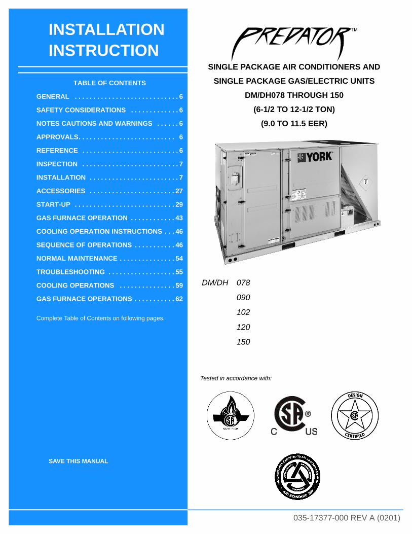
INSTALLATION INSTRUCTION
SAVE THIS MANUAL
SINGLE PACKAGE AIR CONDITIONERS AND
SINGLE PACKAGE GAS/ELECTRIC UNITS
DM/DH078 THROUGH 150
(6-1/2 TO 12-1/2 TON)
(9.0 TO 11.5 EER)
035-17377-000 REV A (0201)
DM/DH 078
090
102
120
150
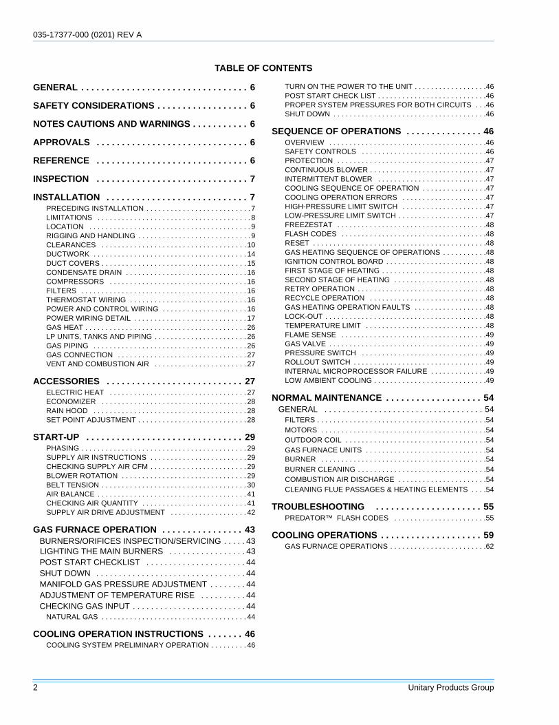
TABLE OF CONTENTS
GENERAL . . . . . . . . . . . . . . . . . . . . . . . . . . . . 6
SAFETY CONSIDERATIONS . . . . . . . . . . . . . 6
NOTES CAUTIONS AND WARNINGS . . . . . . 6
APPROVALS. . . . . . . . . . . . . . . . . . . . . . . . . . 6
REFERENCE . . . . . . . . . . . . . . . . . . . . . . . . . . 6
INSPECTION . . . . . . . . . . . . . . . . . . . . . . . . . . 7
INSTALLATION . . . . . . . . . . . . . . . . . . . . . . . . 7
ACCESSORIES . . . . . . . . . . . . . . . . . . . . . . . 27
START-UP . . . . . . . . . . . . . . . . . . . . . . . . . . . 29
GAS FURNACE OPERATION . . . . . . . . . . . . 43
COOLING OPERATION INSTRUCTIONS . . . 46
SEQUENCE OF OPERATIONS . . . . . . . . . . . 46
NORMAL MAINTENANCE . . . . . . . . . . . . . . . 54
TROUBLESHOOTING . . . . . . . . . . . . . . . . . . 55
COOLING OPERATIONS . . . . . . . . . . . . . . . 59
GAS FURNACE OPERATIONS . . . . . . . . . . . 62
Complete Table of Contents on following pages.
Tested in accordance with:
035-17377-000 (0201) REV A
2 Unitary Products Group
TABLE OF CONTENTS
GENERAL . . . . . . . . . . . . . . . . . . . . . . . . . . . . . . . . . 6
SAFETY CONSIDERATIONS . . . . . . . . . . . . . . . . . . 6
NOTES CAUTIONS AND WARNINGS . . . . . . . . . . . 6
APPROVALS . . . . . . . . . . . . . . . . . . . . . . . . . . . . . . 6
REFERENCE . . . . . . . . . . . . . . . . . . . . . . . . . . . . . . 6
INSPECTION . . . . . . . . . . . . . . . . . . . . . . . . . . . . . . 7
INSTALLATION . . . . . . . . . . . . . . . . . . . . . . . . . . . . 7PRECEDING INSTALLATION . . . . . . . . . . . . . . . . . . . . . . . . . . 7LIMITATIONS . . . . . . . . . . . . . . . . . . . . . . . . . . . . . . . . . . . . . . 8LOCATION . . . . . . . . . . . . . . . . . . . . . . . . . . . . . . . . . . . . . . . . 9RIGGING AND HANDLING . . . . . . . . . . . . . . . . . . . . . . . . . . . . 9CLEARANCES . . . . . . . . . . . . . . . . . . . . . . . . . . . . . . . . . . . . 10DUCTWORK . . . . . . . . . . . . . . . . . . . . . . . . . . . . . . . . . . . . . . 14DUCT COVERS . . . . . . . . . . . . . . . . . . . . . . . . . . . . . . . . . . . . 15CONDENSATE DRAIN . . . . . . . . . . . . . . . . . . . . . . . . . . . . . . 16COMPRESSORS . . . . . . . . . . . . . . . . . . . . . . . . . . . . . . . . . . 16FILTERS . . . . . . . . . . . . . . . . . . . . . . . . . . . . . . . . . . . . . . . . . 16THERMOSTAT WIRING . . . . . . . . . . . . . . . . . . . . . . . . . . . . . 16POWER AND CONTROL WIRING . . . . . . . . . . . . . . . . . . . . . 16POWER WIRING DETAIL . . . . . . . . . . . . . . . . . . . . . . . . . . . . 17GAS HEAT . . . . . . . . . . . . . . . . . . . . . . . . . . . . . . . . . . . . . . . . 26LP UNITS, TANKS AND PIPING . . . . . . . . . . . . . . . . . . . . . . . 26GAS PIPING . . . . . . . . . . . . . . . . . . . . . . . . . . . . . . . . . . . . . . 26GAS CONNECTION . . . . . . . . . . . . . . . . . . . . . . . . . . . . . . . . 27VENT AND COMBUSTION AIR . . . . . . . . . . . . . . . . . . . . . . . 27
ACCESSORIES . . . . . . . . . . . . . . . . . . . . . . . . . . . 27ELECTRIC HEAT . . . . . . . . . . . . . . . . . . . . . . . . . . . . . . . . . . 27ECONOMIZER . . . . . . . . . . . . . . . . . . . . . . . . . . . . . . . . . . . . 28RAIN HOOD . . . . . . . . . . . . . . . . . . . . . . . . . . . . . . . . . . . . . . 28SET POINT ADJUSTMENT . . . . . . . . . . . . . . . . . . . . . . . . . . . 28
START-UP . . . . . . . . . . . . . . . . . . . . . . . . . . . . . . . 29PHASING . . . . . . . . . . . . . . . . . . . . . . . . . . . . . . . . . . . . . . . . . 29SUPPLY AIR INSTRUCTIONS . . . . . . . . . . . . . . . . . . . . . . . . 29CHECKING SUPPLY AIR CFM . . . . . . . . . . . . . . . . . . . . . . . . 29BLOWER ROTATION . . . . . . . . . . . . . . . . . . . . . . . . . . . . . . . 29BELT TENSION . . . . . . . . . . . . . . . . . . . . . . . . . . . . . . . . . . . . 30AIR BALANCE . . . . . . . . . . . . . . . . . . . . . . . . . . . . . . . . . . . . . 41CHECKING AIR QUANTITY . . . . . . . . . . . . . . . . . . . . . . . . . . 41SUPPLY AIR DRIVE ADJUSTMENT . . . . . . . . . . . . . . . . . . . 42
GAS FURNACE OPERATION . . . . . . . . . . . . . . . . 43BURNERS/ORIFICES INSPECTION/SERVICING . . . . . 43
LIGHTING THE MAIN BURNERS . . . . . . . . . . . . . . . . . 43POST START CHECKLIST . . . . . . . . . . . . . . . . . . . . . . 44SHUT DOWN . . . . . . . . . . . . . . . . . . . . . . . . . . . . . . . . . 44MANIFOLD GAS PRESSURE ADJUSTMENT . . . . . . . . 44ADJUSTMENT OF TEMPERATURE RISE . . . . . . . . . . 44CHECKING GAS INPUT . . . . . . . . . . . . . . . . . . . . . . . . . 44
NATURAL GAS . . . . . . . . . . . . . . . . . . . . . . . . . . . . . . . . . . . . 44
COOLING OPERATION INSTRUCTIONS . . . . . . . 46COOLING SYSTEM PRELIMINARY OPERATION . . . . . . . . . 46
TURN ON THE POWER TO THE UNIT . . . . . . . . . . . . . . . . . .46POST START CHECK LIST . . . . . . . . . . . . . . . . . . . . . . . . . . .46PROPER SYSTEM PRESSURES FOR BOTH CIRCUITS . . .46SHUT DOWN . . . . . . . . . . . . . . . . . . . . . . . . . . . . . . . . . . . . . .46
SEQUENCE OF OPERATIONS . . . . . . . . . . . . . . . 46OVERVIEW . . . . . . . . . . . . . . . . . . . . . . . . . . . . . . . . . . . . . . .46SAFETY CONTROLS . . . . . . . . . . . . . . . . . . . . . . . . . . . . . . .46PROTECTION . . . . . . . . . . . . . . . . . . . . . . . . . . . . . . . . . . . . .47CONTINUOUS BLOWER . . . . . . . . . . . . . . . . . . . . . . . . . . . . .47INTERMITTENT BLOWER . . . . . . . . . . . . . . . . . . . . . . . . . . .47COOLING SEQUENCE OF OPERATION . . . . . . . . . . . . . . . .47COOLING OPERATION ERRORS . . . . . . . . . . . . . . . . . . . . .47HIGH-PRESSURE LIMIT SWITCH . . . . . . . . . . . . . . . . . . . . .47LOW-PRESSURE LIMIT SWITCH . . . . . . . . . . . . . . . . . . . . . .47FREEZESTAT . . . . . . . . . . . . . . . . . . . . . . . . . . . . . . . . . . . . .48FLASH CODES . . . . . . . . . . . . . . . . . . . . . . . . . . . . . . . . . . . .48RESET . . . . . . . . . . . . . . . . . . . . . . . . . . . . . . . . . . . . . . . . . . .48GAS HEATING SEQUENCE OF OPERATIONS . . . . . . . . . . .48IGNITION CONTROL BOARD . . . . . . . . . . . . . . . . . . . . . . . . .48FIRST STAGE OF HEATING . . . . . . . . . . . . . . . . . . . . . . . . . .48SECOND STAGE OF HEATING . . . . . . . . . . . . . . . . . . . . . . .48RETRY OPERATION . . . . . . . . . . . . . . . . . . . . . . . . . . . . . . . .48RECYCLE OPERATION . . . . . . . . . . . . . . . . . . . . . . . . . . . . .48GAS HEATING OPERATION FAULTS . . . . . . . . . . . . . . . . . .48LOCK-OUT . . . . . . . . . . . . . . . . . . . . . . . . . . . . . . . . . . . . . . . .48TEMPERATURE LIMIT . . . . . . . . . . . . . . . . . . . . . . . . . . . . . .48FLAME SENSE . . . . . . . . . . . . . . . . . . . . . . . . . . . . . . . . . . . .49GAS VALVE . . . . . . . . . . . . . . . . . . . . . . . . . . . . . . . . . . . . . . .49PRESSURE SWITCH . . . . . . . . . . . . . . . . . . . . . . . . . . . . . . .49ROLLOUT SWITCH . . . . . . . . . . . . . . . . . . . . . . . . . . . . . . . . .49INTERNAL MICROPROCESSOR FAILURE . . . . . . . . . . . . . .49LOW AMBIENT COOLING . . . . . . . . . . . . . . . . . . . . . . . . . . . .49
NORMAL MAINTENANCE . . . . . . . . . . . . . . . . . . . 54GENERAL . . . . . . . . . . . . . . . . . . . . . . . . . . . . . . . . . . . 54
FILTERS . . . . . . . . . . . . . . . . . . . . . . . . . . . . . . . . . . . . . . . . . .54MOTORS . . . . . . . . . . . . . . . . . . . . . . . . . . . . . . . . . . . . . . . . .54OUTDOOR COIL . . . . . . . . . . . . . . . . . . . . . . . . . . . . . . . . . . .54GAS FURNACE UNITS . . . . . . . . . . . . . . . . . . . . . . . . . . . . . .54BURNER . . . . . . . . . . . . . . . . . . . . . . . . . . . . . . . . . . . . . . . . .54BURNER CLEANING . . . . . . . . . . . . . . . . . . . . . . . . . . . . . . . .54COMBUSTION AIR DISCHARGE . . . . . . . . . . . . . . . . . . . . . .54CLEANING FLUE PASSAGES & HEATING ELEMENTS . . . .54
TROUBLESHOOTING . . . . . . . . . . . . . . . . . . . . . 55PREDATOR™ FLASH CODES . . . . . . . . . . . . . . . . . . . . . . .55
COOLING OPERATIONS . . . . . . . . . . . . . . . . . . . . 59GAS FURNACE OPERATIONS . . . . . . . . . . . . . . . . . . . . . . . .62
035-17377-000 REV A (0201)
Unitary Products Group 3
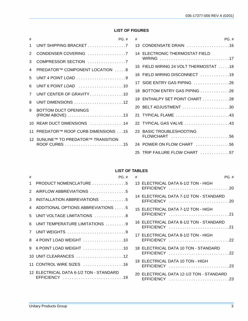
LIST OF FIGURES
# PG. #
1 UNIT SHIPPING BRACKET . . . . . . . . . . . . . . . . .7
2 CONDENSER COVERING . . . . . . . . . . . . . . . . .7
3 COMPRESSOR SECTION . . . . . . . . . . . . . . . . .7
4 PREDATOR™ COMPONENT LOCATION . . . . .8
5 UNIT 4 POINT LOAD . . . . . . . . . . . . . . . . . . . . . .9
6 UNIT 6 POINT LOAD . . . . . . . . . . . . . . . . . . . .10
7 UNIT CENTER OF GRAVITY . . . . . . . . . . . . . . .10
8 UNIT DIMENSIONS . . . . . . . . . . . . . . . . . . . . . .12
9 BOTTOM DUCT OPENINGS (FROM ABOVE) . . . . . . . . . . . . . . . . . . . . . . . . .13
10 REAR DUCT DIMENSIONS . . . . . . . . . . . . . . .14
11 PREDATOR™ ROOF CURB DIMENSIONS . . .15
12 SUNLINE™ TO PREDATOR™ TRANSITION ROOF CURBS . . . . . . . . . . . . . . . . . . . . . . . . . .15
# PG. #
13 CONDENSATE DRAIN . . . . . . . . . . . . . . . . . . .16
14 ELECTRONIC THERMOSTAT FIELD WIRING . . . . . . . . . . . . . . . . . . . . . . . . . . . . . . .17
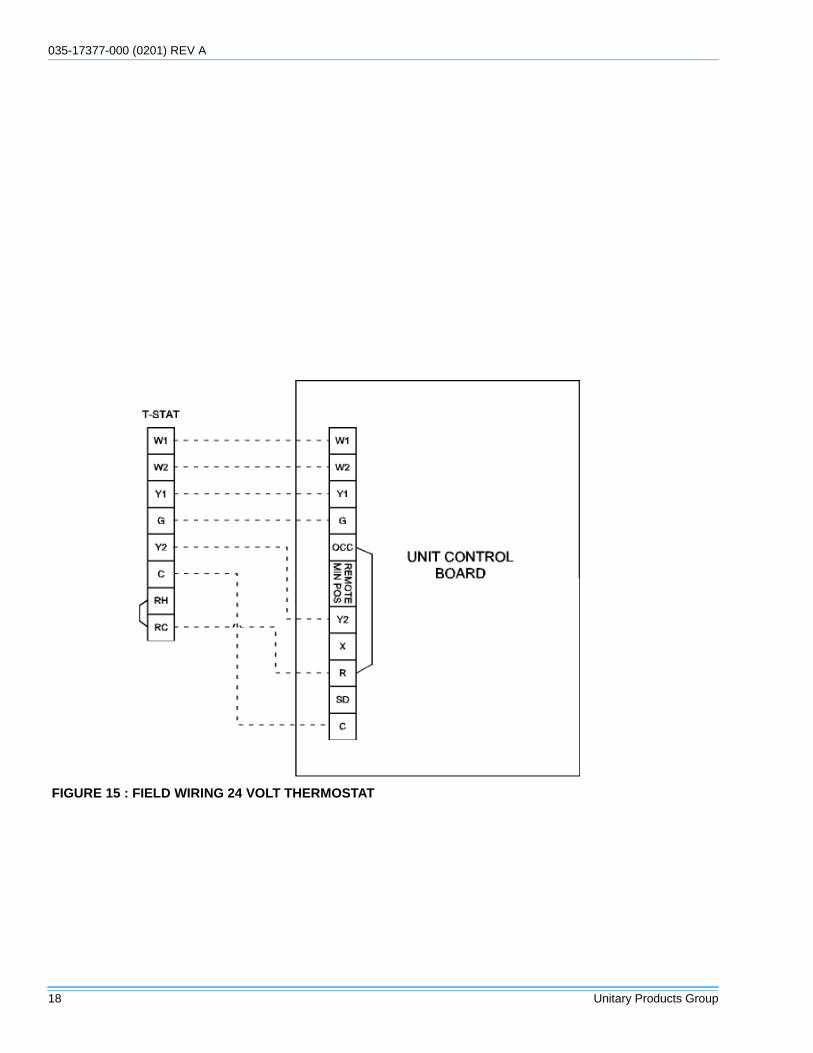
15 FIELD WIRING 24 VOLT THERMOSTAT . . . . .18
16 FIELD WIRING DISCONNECT . . . . . . . . . . . . .19
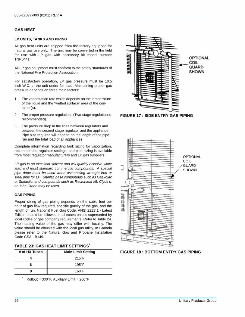
17 SIDE ENTRY GAS PIPING . . . . . . . . . . . . . . . .26
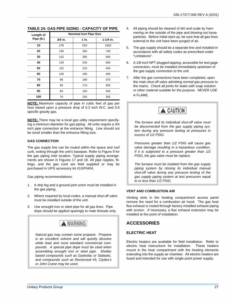
18 BOTTOM ENTRY GAS PIPING . . . . . . . . . . . . .26
19 ENTHALPY SET POINT CHART . . . . . . . . . . . .28
20 BELT ADJUSTMENT . . . . . . . . . . . . . . . . . . . . .30
21 TYPICAL FLAME . . . . . . . . . . . . . . . . . . . . . . . .43
22 TYPICAL GAS VALVE . . . . . . . . . . . . . . . . . . . .43
23 BASIC TROUBLESHOOTING FLOWCHART . . . . . . . . . . . . . . . . . . . . . . . . . .56
24 POWER ON FLOW CHART . . . . . . . . . . . . . . .56
25 TRIP FAILURE FLOW CHART . . . . . . . . . . . . .57
LIST OF TABLES
# PG. #
1 PRODUCT NOMENCLATURE . . . . . . . . . . . . . . .5
2 AIRFLOW ABBREVIATIONS . . . . . . . . . . . . . . . .5
3 INSTALLATION ABBREVIATIONS . . . . . . . . . . .5
4 ADDITIONAL OPTIONS ABBREVIATIONS . . . . .5
5 UNIT VOLTAGE LIMITATIONS . . . . . . . . . . . . . .8
6 UNIT TEMPERATURE LIMITATIONS . . . . . . . . .9
7 UNIT WEIGHTS . . . . . . . . . . . . . . . . . . . . . . . . . .9
8 4 POINT LOAD WEIGHT . . . . . . . . . . . . . . . . . .10
9 6 POINT LOAD WEIGHT . . . . . . . . . . . . . . . . . .10
10 UNIT CLEARANCES . . . . . . . . . . . . . . . . . . . . .12
11 CONTROL WIRE SIZES . . . . . . . . . . . . . . . . . .16
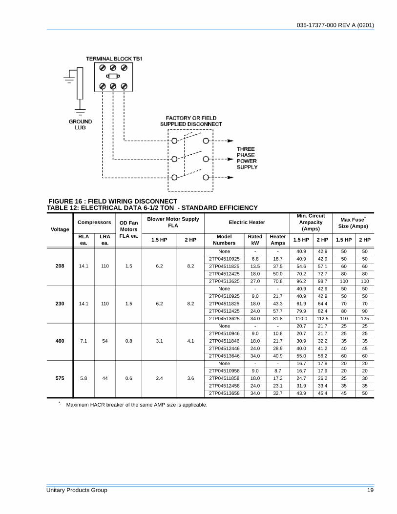
12 ELECTRICAL DATA 6-1/2 TON - STANDARD EFFICIENCY . . . . . . . . . . . . . . . . . . . . . . . . . . .19
# PG. #
13 ELECTRICAL DATA 6-1/2 TON - HIGH EFFICIENCY . . . . . . . . . . . . . . . . . . . . . . . . . . .20
14 ELECTRICAL DATA 7-1/2 TON - STANDARD EFFICIENCY . . . . . . . . . . . . . . . . . . . . . . . . . . .20
15 ELECTRICAL DATA 7-1/2 TON - HIGH EFFICIENCY . . . . . . . . . . . . . . . . . . . . . . . . . . .21
16 ELECTRICAL DATA 8-1/2 TON - STANDARD EFFICIENCY . . . . . . . . . . . . . . . . . . . . . . . . . . .21
17 ELECTRICAL DATA 8-1/2 TON - HIGH EFFICIENCY . . . . . . . . . . . . . . . . . . . . . . . . . . .22
18 ELECTRICAL DATA 10 TON - STANDARD EFFICIENCY . . . . . . . . . . . . . . . . . . . . . . . . . . .22
19 ELECTRICAL DATA 10 TON - HIGH EFFICIENCY . . . . . . . . . . . . . . . . . . . . . . . . . . .23
20 ELECTRICAL DATA 12-1/2 TON - STANDARD EFFICIENCY . . . . . . . . . . . . . . . . . . . . . . . . . . .23
035-17377-000 (0201) REV A
4 Unitary Products Group
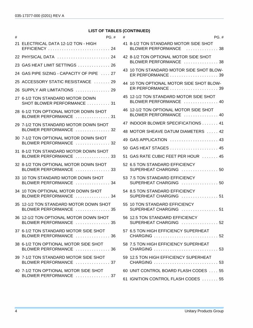
LIST OF TABLES (CONTINUED)
# PG. #
21 ELECTRICAL DATA 12-1/2 TON - HIGH EFFICIENCY . . . . . . . . . . . . . . . . . . . . . . . . . . . 24
22 PHYSICAL DATA . . . . . . . . . . . . . . . . . . . . . . . 24
23 GAS HEAT LIMIT SETTINGS . . . . . . . . . . . . . . 26
24 GAS PIPE SIZING - CAPACITY OF PIPE . . . . 27
25 ACCESSORY STATIC RESISTANCE . . . . . . . 29
26 SUPPLY AIR LIMITATIONS . . . . . . . . . . . . . . . 29
27 6-1/2 TON STANDARD MOTOR DOWN SHOT BLOWER PERFORMANCE . . . . . . . . . . 31
28 6-1/2 TON OPTIONAL MOTOR DOWN SHOT BLOWER PERFORMANCE . . . . . . . . . . . . . . . 31
29 7-1/2 TON STANDARD MOTOR DOWN SHOT BLOWER PERFORMANCE . . . . . . . . . . . . . . . 32
30 7-1/2 TON OPTIONAL MOTOR DOWN SHOT BLOWER PERFORMANCE . . . . . . . . . . . . . . . 32
31 8-1/2 TON STANDARD MOTOR DOWN SHOT BLOWER PERFORMANCE . . . . . . . . . . . . . . . 33
32 8-1/2 TON OPTIONAL MOTOR DOWN SHOT BLOWER PERFORMANCE . . . . . . . . . . . . . . . 33
33 10 TON STANDARD MOTOR DOWN SHOT BLOWER PERFORMANCE . . . . . . . . . . . . . . . 34
34 10 TON OPTIONAL MOTOR DOWN SHOT BLOWER PERFORMANCE . . . . . . . . . . . . . . . 34
35 12-1/2 TON STANDARD MOTOR DOWN SHOT BLOWER PERFORMANCE . . . . . . . . . . . . . . . 35
36 12-1/2 TON OPTIONAL MOTOR DOWN SHOT BLOWER PERFORMANCE . . . . . . . . . . . . . . . 35
37 6-1/2 TON STANDARD MOTOR SIDE SHOT BLOWER PERFORMANCE . . . . . . . . . . . . . . . 36
38 6-1/2 TON OPTIONAL MOTOR SIDE SHOT BLOWER PERFORMANCE . . . . . . . . . . . . . . . 36
39 7-1/2 TON STANDARD MOTOR SIDE SHOT BLOWER PERFORMANCE . . . . . . . . . . . . . . . 37
40 7-1/2 TON OPTIONAL MOTOR SIDE SHOT BLOWER PERFORMANCE . . . . . . . . . . . . . . . 37
# PG. #
41 8-1/2 TON STANDARD MOTOR SIDE SHOT BLOWER PERFORMANCE . . . . . . . . . . . . . . 38
42 8-1/2 TON OPTIONAL MOTOR SIDE SHOT BLOWER PERFORMANCE . . . . . . . . . . . . . . . 38
43 10 TON STANDARD MOTOR SIDE SHOT BLOW-ER PERFORMANCE . . . . . . . . . . . . . . . . . . . . . 39
44 10 TON OPTIONAL MOTOR SIDE SHOT BLOW-ER PERFORMANCE . . . . . . . . . . . . . . . . . . . . . 39
45 12-1/2 TON STANDARD MOTOR SIDE SHOT BLOWER PERFORMANCE . . . . . . . . . . . . . . . 40
46 12-1/2 TON OPTIONAL MOTOR SIDE SHOT BLOWER PERFORMANCE . . . . . . . . . . . . . . . 40
47 INDOOR BLOWER SPECIFICATIONS . . . . . . . 41
48 MOTOR SHEAVE DATUM DIAMETERS . . . . . 42
49 GAS APPLICATION . . . . . . . . . . . . . . . . . . . . . 43
50 GAS HEAT STAGES . . . . . . . . . . . . . . . . . . . . . 45
51 GAS RATE CUBIC FEET PER HOUR . . . . . . . 45
52 6.5 TON STANDARD EFFICIENCY SUPERHEAT CHARGING . . . . . . . . . . . . . . . . 50
53 7.5 TON STANDARD EFFICIENCY SUPERHEAT CHARGING . . . . . . . . . . . . . . . . 50
54 8.5 TON STANDARD EFFICIENCY SUPERHEAT CHARGING . . . . . . . . . . . . . . . . 51
55 10 TON STANDARD EFFICIENCY SUPERHEAT CHARGING . . . . . . . . . . . . . . . . 51
56 12.5 TON STANDARD EFFICIENCY SUPERHEAT CHARGING . . . . . . . . . . . . . . . . 52
57 6.5 TON HIGH EFFICIENCY SUPERHEAT CHARGING . . . . . . . . . . . . . . . . . . . . . . . . . . . . 52
58 7.5 TON HIGH EFFICIENCY SUPERHEAT CHARGING . . . . . . . . . . . . . . . . . . . . . . . . . . . . 53
59 12.5 TON HIGH EFFICIENCY SUPERHEAT CHARGING . . . . . . . . . . . . . . . . . . . . . . . . . . . . 53
60 UNIT CONTROL BOARD FLASH CODES . . . . 55
61 IGNITION CONTROL FLASH CODES . . . . . . . 55
035-17377-000 REV A (0201)
Unitary Products Group 5
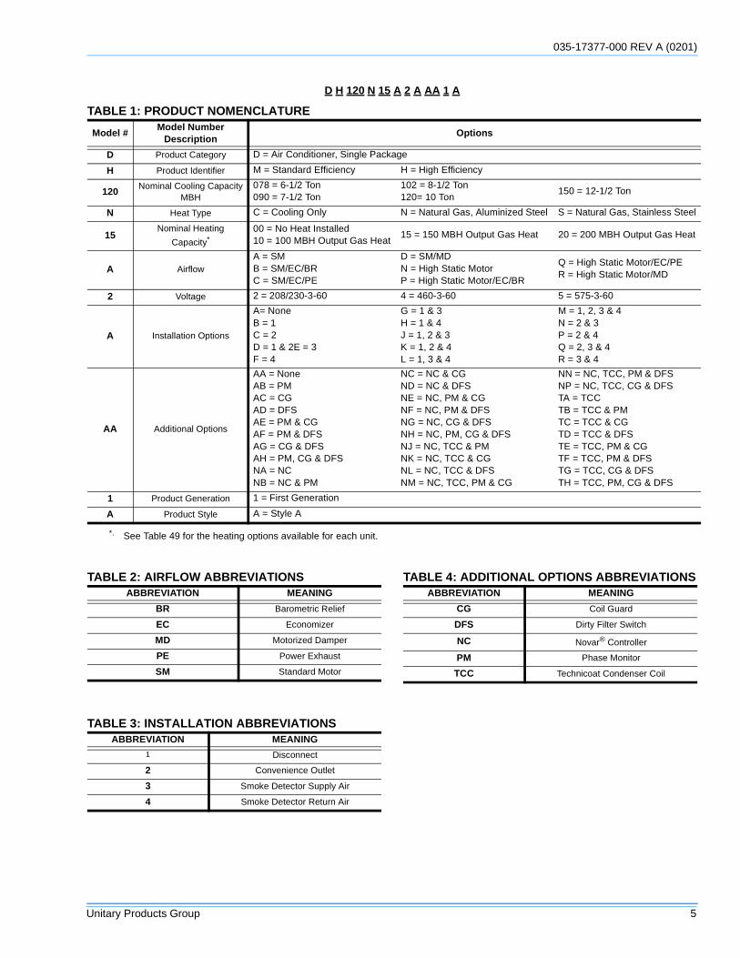
D H 120 N 15 A 2 A AA 1 A
TABLE 1: PRODUCT NOMENCLATURE
Model #Model Number
DescriptionOptions
D Product Category D = Air Conditioner, Single Package
H Product Identifier M = Standard Efficiency H = High Efficiency
120Nominal Cooling Capacity
MBH078 = 6-1/2 Ton090 = 7-1/2 Ton
102 = 8-1/2 Ton120= 10 Ton
150 = 12-1/2 Ton
N Heat Type C = Cooling Only N = Natural Gas, Aluminized Steel S = Natural Gas, Stainless Steel
15Nominal Heating
Capacity*
*. See Table 49 for the heating options available for each unit.
00 = No Heat Installed10 = 100 MBH Output Gas Heat
15 = 150 MBH Output Gas Heat 20 = 200 MBH Output Gas Heat
A AirflowA = SMB = SM/EC/BRC = SM/EC/PE
D = SM/MDN = High Static MotorP = High Static Motor/EC/BR
Q = High Static Motor/EC/PER = High Static Motor/MD
2 Voltage 2 = 208/230-3-60 4 = 460-3-60 5 = 575-3-60
A Installation Options
A= NoneB = 1C = 2D = 1 & 2E = 3F = 4
G = 1 & 3H = 1 & 4J = 1, 2 & 3K = 1, 2 & 4L = 1, 3 & 4
M = 1, 2, 3 & 4N = 2 & 3P = 2 & 4Q = 2, 3 & 4R = 3 & 4
AA Additional Options
AA = NoneAB = PMAC = CGAD = DFSAE = PM & CGAF = PM & DFSAG = CG & DFSAH = PM, CG & DFSNA = NCNB = NC & PM
NC = NC & CGND = NC & DFSNE = NC, PM & CGNF = NC, PM & DFSNG = NC, CG & DFSNH = NC, PM, CG & DFSNJ = NC, TCC & PMNK = NC, TCC & CGNL = NC, TCC & DFSNM = NC, TCC, PM & CG
NN = NC, TCC, PM & DFSNP = NC, TCC, CG & DFSTA = TCCTB = TCC & PMTC = TCC & CGTD = TCC & DFSTE = TCC, PM & CGTF = TCC, PM & DFSTG = TCC, CG & DFSTH = TCC, PM, CG & DFS
1 Product Generation 1 = First Generation
A Product Style A = Style A
TABLE 2: AIRFLOW ABBREVIATIONSABBREVIATION MEANING
BR Barometric Relief
EC Economizer
MD Motorized Damper
PE Power Exhaust
SM Standard Motor
TABLE 3: INSTALLATION ABBREVIATIONSABBREVIATION MEANING
1 Disconnect
2 Convenience Outlet
3 Smoke Detector Supply Air
4 Smoke Detector Return Air
TABLE 4: ADDITIONAL OPTIONS ABBREVIATIONSABBREVIATION MEANING
CG Coil Guard
DFS Dirty Filter Switch
NC Novar® Controller
PM Phase Monitor
TCC Technicoat Condenser Coil
035-17377-000 (0201) REV A
6 Unitary Products Group
GENERAL
YORK Predatorunits are single package air conditionerswith optional gas heating designed for outdoor installation ona rooftop or slab and for non-residential use. These units canbe equipped with field installed electric heaters for heatingapplications.
These units are completely assembled on rigid, permanentlyattached base rails. All piping, refrigerant charge, and electri-cal wiring is factory installed and tested. The units requireelectric power, gas supply (where applicable), and duct con-nections. The electric heaters have nickel-chrome elementsand utilize single-point power connection.
SAFETY CONSIDERATIONS
Due to system pressure, moving parts, and electrical compo-nents, installation and servicing of air conditioning equipmentcan be hazardous. Only qualified, trained service personnelshould install, repair, or service this equipment. Untrainedpersonnel can perform basic maintenance functions of clean-ing coils and filters and replacing filters.
Observe all precautions in the literature, labels, and tagsaccompanying the equipment whenever working on air condi-tioning equipment. Be sure to follow all other applicablesafety precautions and codes including ANSI Z223.1 - latestedition. Wear safety glasses and work gloves. Use quench-ing cloth and have a fire extinguisher available during brazingoperations.
NOTES CAUTIONS AND WARNINGS
Installer should pay particular attention to the words: NOTE,CAUTION, and WARNING. Notes are intended to clarify ormake the installation easier. CAUTIONS are given to preventequipment damage. WARNINGS are given to alert installerthat personal injury and/or equipment damage may result ifinstallation procedure is not handled properly.
APPROVALS
Design certified by CSA as follows:
1. For use as a cooling only unit, cooling unit with supple-mental electric heat or a forced air furnace.
2. For outdoor installation only.
3. For installation on combustible material and may be installed directly on combustible flooring or, in the U.S., on wood flooring or Class A, Class B or Class C roof cov-ering materials.
4. For use with natural gas (convertible to LP with kit).
REFERENCE
Additional information is available in the following referenceforms:
• - Technical Guide• - General Installation• - Pre-start & Post-start Check List• - Economizer Accessory• - Motorized Outdoor Air Damper• - Manual Outdoor Air Damper (0-100%)• - Manual Outdoor Air Damper (0-35%)• - Gas Heat Propane Conversion Kit• - Gas Heat High Altitude Kit (Natural Gas)• - Gas Heat High Altitude Kit (Propane)• - –60°F Gas Heat Kit• - Electric Heater Accessory• - Low Ambient Accessory• - Unit Renewal Parts List
If the information in this manual is not followedexactly, a fire or explosion may result causingproperty damage, personal injury or loss of life.
Do not store or use gasoline or other flammablevapors and liquids in the vicinity of this or anyother appliance.
WHAT TO DO IF YOU SMELL GAS
a. Do not try to light any appliance.
b. Do not touch any electrical switch; do not useany phone in your building.
c. Immediately call your gas supplier from a neigh-bor’s phone. Follow the gas supplier’s instruc-tions.
d. If you cannot reach your gas supplier, call the firedepartment.
Installation and service must be performed by aqualified installer, service agency or the gas sup-plier.
Should overheating occur, or the gas supply fail toshut off, shut off the manual gas valve to the fur-nace before shutting off the electrical supply.
Do not use this furnace if any part has been underwater. Immediately call a qualified service techni-cian to inspect the furnace and to replace any partof the control system and any gas control whichhas been under water.
035-17377-000 REV A (0201)
Unitary Products Group 7
All forms referenced in this instruction may be ordered from:
Standard Register2101 West Tecumseh RoadNorman, OK 73069Toll Free Fax: (877) 379-7920Toll Free Phone: (877) 318-9675
INSPECTION
As soon as a unit is received, it should be inspected for possi-ble damage during transit. If damage is evident, the extent ofthe damage should be noted on the carrier’s freight bill. Aseparate request for inspection by the carrier’s agent should
be made in writing.
INSTALLATION
PRECEDING INSTALLATION
1. Remove the two screws holding the brackets in the front, rear and compressor side fork-lift slots.
2. Turn each bracket toward the ground and the protective plywood covering will drop to the ground.
3. Remove the condenser coil external protective covering prior to operation.
4. Remove the toolless doorknobs and instruction packet prior to installation.
LIMITATIONS
These units must be installed in accordance with the follow-ing:
This furnace is not to be used for temporary heat-ing of buildings or structures under construction.
Before performing service or maintenance opera-tions on unit, turn off main power switch to unit.Electrical shock could cause personal injury.Improper installation, adjustment, alteration, ser-vice or maintenance can cause injury or propertydamage. Refer to this manual. For assistance oradditional information consult a qualified installer,service agency or the gas supplier.
FIGURE 1 : UNIT SHIPPING BRACKET
BracketScrews Turn down
This product must be installed in strict compliance with the enclosed installation instructions and any applicable local, state and national codes includ-ing, but not limited to, building, electrical, and mechanical codes.
The furnace and its individual shut-off valve mustbe disconnected from the gas supply piping sys-tem during any pressure testing at pressures inexcess of 1/2 PSIG.
Pressures greater than 1/2 PSIG will cause gasvalve damage resulting in a hazardous condition.If it is subjected to a pressure greater than 1/2PSIG, the gas valve must be replaced.
The furnace must be isolated from the gas supplypiping system by closing its individual manualshut-off valve during any pressure testing of thegas supply piping system at test pressures equalto or less than 1/2 PSIG
FIGURE 2 : CONDENSER COVERING
FIGURE 3 : COMPRESSOR SECTION
CondenserCoil ExternalProtectiveCovering
Barometric Relief Hood in Shipping Loca-tion (if included)
ToollessDoorknobs
InstallationInstructionPacket
035-17377-000 (0201) REV A
8 Unitary Products Group
In U.S.A.:
1. National Electrical Code, ANSI/NFPA No. 70 - Latest Edition
2. National Fuel Gas Code, ANSI Z223.1 - Latest Edition,
3. Gas-Fired Central Furnace Standard, ANSI Z21.47 - Lat-est Edition
4. Local building codes, and
5. Local gas utility requirements.
In Canada:
1. Canadian Electrical Code, CSA C22.1,
2. Installation Codes, CSA - B149,
3. Local plumbing and waste water codes, and
4. Other applicable local codes.
Refer to Tables 5 & 6 for unit application data.
After installation, gas fired units must be adjusted to obtain atemperature rise within the range specified on the unit ratingplate.
If components are to be added to a unit to meet local codes,they are to be installed at the dealer’s and/or customer’sexpense.
Size of unit for proposed installation should be based on heatloss/heat gain calculation made according to the methods ofAir Conditioning Contractors of America (ACCA).
FIGURE 4 : PREDATOR™ COMPONENT LOCATION
Slide-Out Drain Pan w/ Steel 3/4” FPT Connection
Power Ventor Motor
Compressor #1 Access (High-Eff Compressor w/ crankcase heater)
Belt-Drive Blower Motor
Terminal Block for Hi-Voltage Connection
Control Board w/ ScrewConnector for T-stat Wiring
Disconnect Location(Optional Disconnect Switch)
Filter Access(2” Filters)
Filter-Drier (Solid Core)
Condenser Section
Two-stage gas heat-ing to maintain warm, comfortable temperature
Intelligent control board for safe and efficient operation
Side entry power and control wiring knockouts
Tool-less door latch
TABLE 5: UNIT VOLTAGE LIMITATIONS
Power Rating*
*. Utilization range “A” in accordance with ARI Standard 110.
Minimum Maximum
208/230-3-60 187 252
460-3-60 432 504
575-3-60 540 630
Base Rails w/ Forklift Slots (3 Sides) & Lifting Holes
Second model nameplate inside hinged access panel
Compressor #2 Access (High-Eff Compressor w/ crankcase heater)
Dual stage cooling for maximum comfort
Slide-out motor and blower assembly for easy adjustment and service
Roof curbs in eight- and fourteen-inch heights. Rood curbs for transitioning form Sunline footprint to the DM/DH Series footprint are also available (field-installed accessory)
035-17377-000 REV A (0201)
Unitary Products Group 9
LOCATION
Use the following guidelines to select a suitable location forthese units:
1. Unit is designed for outdoor installation only.
2. Condenser coils must have an unlimited supply of air. Where a choice of location is possible, position the unit on either north or east side of building.
3. Suitable for mounting on roof curb.
4. Roof structures must be able to support the weight of the unit and its options/accessories. Unit must be installed on a solid, level roof curb or appropriate angle iron frame.
5. Maintain level tolerance to 1/2” across the entire width and length of unit.
RIGGING AND HANDLING
Exercise care when moving the unit. Do not remove anypackaging until the unit is near the place of installation. Rigthe unit by attaching chain or cable slings to the lifting holesprovided in the base rails. Spreader bars, whose lengthexceeds the largest dimension across the unit, MUST be
used across the top of the unit.
Before lifting, make sure the unit weight is distributed equallyon the rigging cables so it will lift evenly.
Units may be moved or lifted with a forklift. Slotted openingsin the base rails are provided for this purpose.
Length of forks must be a minimum of 60 inches.
TABLE 6: UNIT TEMPERATURE LIMITATIONS
Temperature Min. Max.
Wet Bulb Temperature (°F) of Air on Evaporator Coil
57 72
Dry Bulb Temperature (°F) of Air on Condenser Coil 0* 125
*. A low ambient accessory is available for operation down to -20°F.
If a unit is to be installed on a roof curb other thana YORK roof curb, gasketing must be applied to allsurfaces that come in contact with the unit under-side.
All panels must be secured in place when the unitis lifted.
The condenser coils should be protected from rig-ging cable damage with plywood or other suitablematerial.
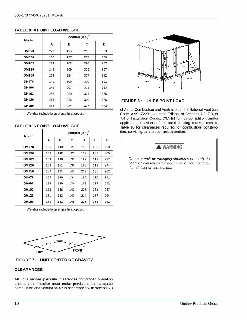
FIGURE 5 : UNIT 4 POINT LOAD
TABLE 7: UNIT WEIGHTSModel Shipping Weight* (lb.) Operating Weight† (lb.)
DM078 1045 1041
DM090 1056 1051
DM102 1089 1084
DM120 1121 1116
DM150 1200 1195
DH078 1104 1099
DH090 1108 1103
DH102 1178 1173
DH120 1212 1207
DH150 1202 1197
Econ. 85 84
w/ PE 150 148
Elec. Heat2 49 49
*. Weights include largest gas heat option.†. 54kW heater.
035-17377-000 (0201) REV A
10 Unitary Products Group
CLEARANCES
All units require particular clearances for proper operationand service. Installer must make provisions for adequatecombustion and ventilation air in accordance with section 5.3
of Air for Combustion and Ventilation of the National Fuel GasCode, ANSI Z223.1 – Latest Edition, or Sections 7.2, 7.3, or7.4 of Installation Codes, CSA-B149 - Latest Edition, and/orapplicable provisions of the local building codes. Refer toTable 10 for clearances required for combustible construc-tion, servicing, and proper unit operation.
TABLE 8: 4 POINT LOAD WEIGHT
ModelLocation (lbs.)*
A B C D
DM078 228 195 285 333
DM090 230 197 287 336
DM102 238 203 296 347
DM120 245 209 305 357
DM150 262 224 327 382
DH078 241 206 300 352
DH090 242 207 301 353
DH102 257 220 321 375
DH120 265 226 330 386
DH150 263 224 327 383
*. Weights include largest gas heat option.
TABLE 9: 6 POINT LOAD WEIGHT
ModelLocation (lbs.)*
*. Weights include largest gas heat option.
A B C D E F
DM078 156 140 127 185 205 228
DM090 158 142 128 187 207 230
DM102 163 146 132 192 213 237
DM120 168 151 136 198 219 244
DM150 180 161 145 212 235 262
DH078 165 148 134 195 216 241
DH090 166 149 134 196 217 242
DH102 176 158 143 208 231 257
DH120 181 163 147 214 237 264
DH150 180 161 146 213 235 262
FIGURE 7 : UNIT CENTER OF GRAVITY
FIGURE 6 : UNIT 6 POINT LOAD
Do not permit overhanging structures or shrubs toobstruct condenser air discharge outlet, combus-tion air inlet or vent outlets.
035-17377-000 REV A (0201)
Unitary Products Group 11
Excessive exposure to contaminated combustionair will result in safety and performance relatedproblems. To maintain combustion air quality, therecommended source of combustion air is the out-door air supply. The outdoor air supplied for com-bustion should be free from contaminants due tochemical exposure that may be present from thefollowing sources.
• Commercial buildings• Indoor pools• Laundry rooms• Hobby or craft rooms• Chemical storage areas
The following substances should be avoided tomaintain outdoor combustion air quality.
• Permanent wave solutions• Chlorinated waxes and cleaners• Chlorine based swimming pool cleaners• Water softening chemicals• De-icing salts or chemicals• Carbon tetrachloride• Halogen type refrigerants• Cleaning solvents (such as perchloroethylene)• Printing inks, paint removers, varnishes, etc.• Hydrochloric acid• Cements and glues• Anti-static fabric softeners for clothes dryers• Masonry acid washing materials
035-17377-000 (0201) REV A
12 Unitary Products Group
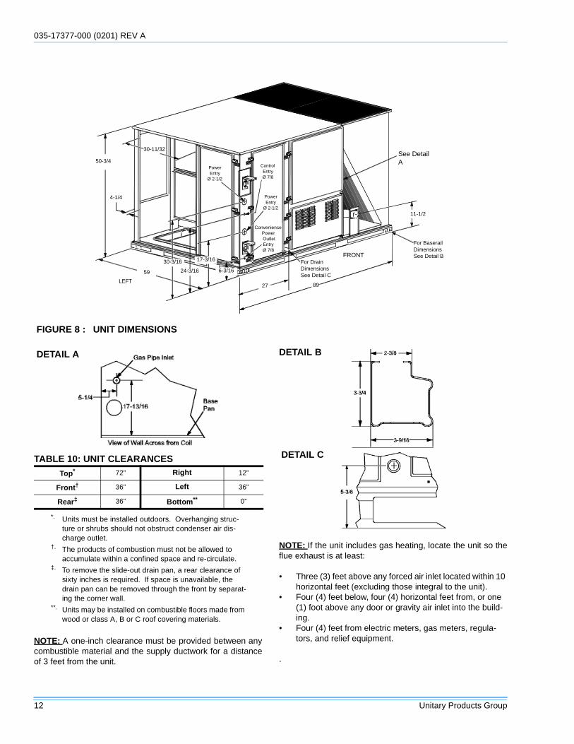
NOTE: A one-inch clearance must be provided between anycombustible material and the supply ductwork for a distanceof 3 feet from the unit.
NOTE: If the unit includes gas heating, locate the unit so theflue exhaust is at least:
• Three (3) feet above any forced air inlet located within 10 horizontal feet (excluding those integral to the unit).
• Four (4) feet below, four (4) horizontal feet from, or one (1) foot above any door or gravity air inlet into the build-ing.
• Four (4) feet from electric meters, gas meters, regula-tors, and relief equipment.
.
FIGURE 8 : UNIT DIMENSIONS
See DetailA
For BaserailDimensionsSee Detail B
8927
59
50-3/4
4-1/4
6-3/16
17-3/16
24-3/16
30-3/16
ConveniencePower OutletEntryØ 7/8
PowerEntry
Ø 2-1/2
11-1/2
30-11/32
ControlEntryØ 7/8
PowerEntry
Ø 2-1/2
LEFT
FRONTFor DrainDimensionsSee Detail C
TABLE 10: UNIT CLEARANCESTop*
*. Units must be installed outdoors. Overhanging struc-ture or shrubs should not obstruct condenser air dis-charge outlet.
72” Right 12”
Front†
†. The products of combustion must not be allowed to accumulate within a confined space and re-circulate.
36” Left 36”
Rear‡
‡. To remove the slide-out drain pan, a rear clearance of sixty inches is required. If space is unavailable, the drain pan can be removed through the front by separat-ing the corner wall.
36” Bottom**
**. Units may be installed on combustible floors made from wood or class A, B or C roof covering materials.
0”
DETAIL A DETAIL B
DETAIL C
035-17377-000 REV A (0201)
Unitary Products Group 13
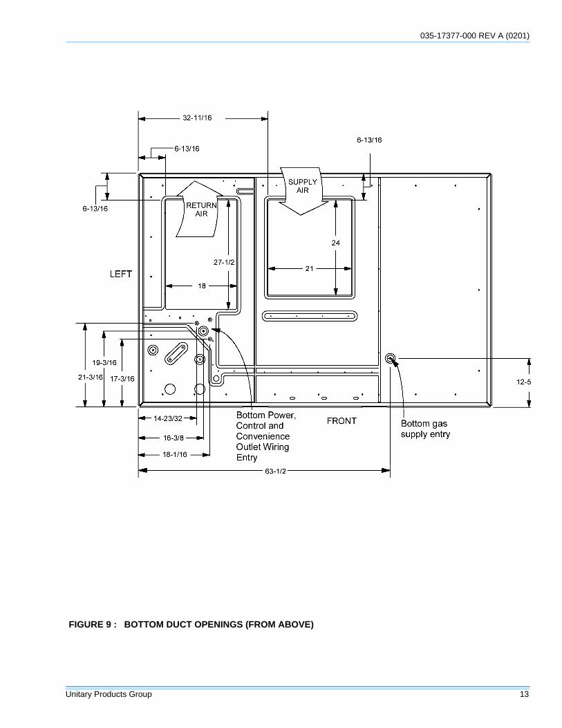
FIGURE 9 : BOTTOM DUCT OPENINGS (FROM ABOVE)
035-17377-000 (0201) REV A
14 Unitary Products Group
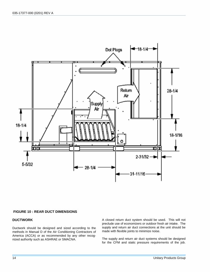
DUCTWORK
Ductwork should be designed and sized according to themethods in Manual D of the Air Conditioning Contractors ofAmerica (ACCA) or as recommended by any other recog-nized authority such as ASHRAE or SMACNA.
A closed return duct system should be used. This will notpreclude use of economizers or outdoor fresh air intake. Thesupply and return air duct connections at the unit should bemade with flexible joints to minimize noise.
The supply and return air duct systems should be designedfor the CFM and static pressure requirements of the job.
FIGURE 10 : REAR DUCT DIMENSIONS
035-17377-000 REV A (0201)
Unitary Products Group 15
They should NOT be sized to match the dimensions of theduct connections on the unit.
Refer to Figure 9 for bottom air duct openings. Refer to Fig-ure 10 for side air duct openings.
DUCT COVERS
Units are shipped with the side duct openings covered. Forbottom duct application, no duct cover changes are neces-sary. For side duct application, remove the side duct coversand install over the bottom duct openings.
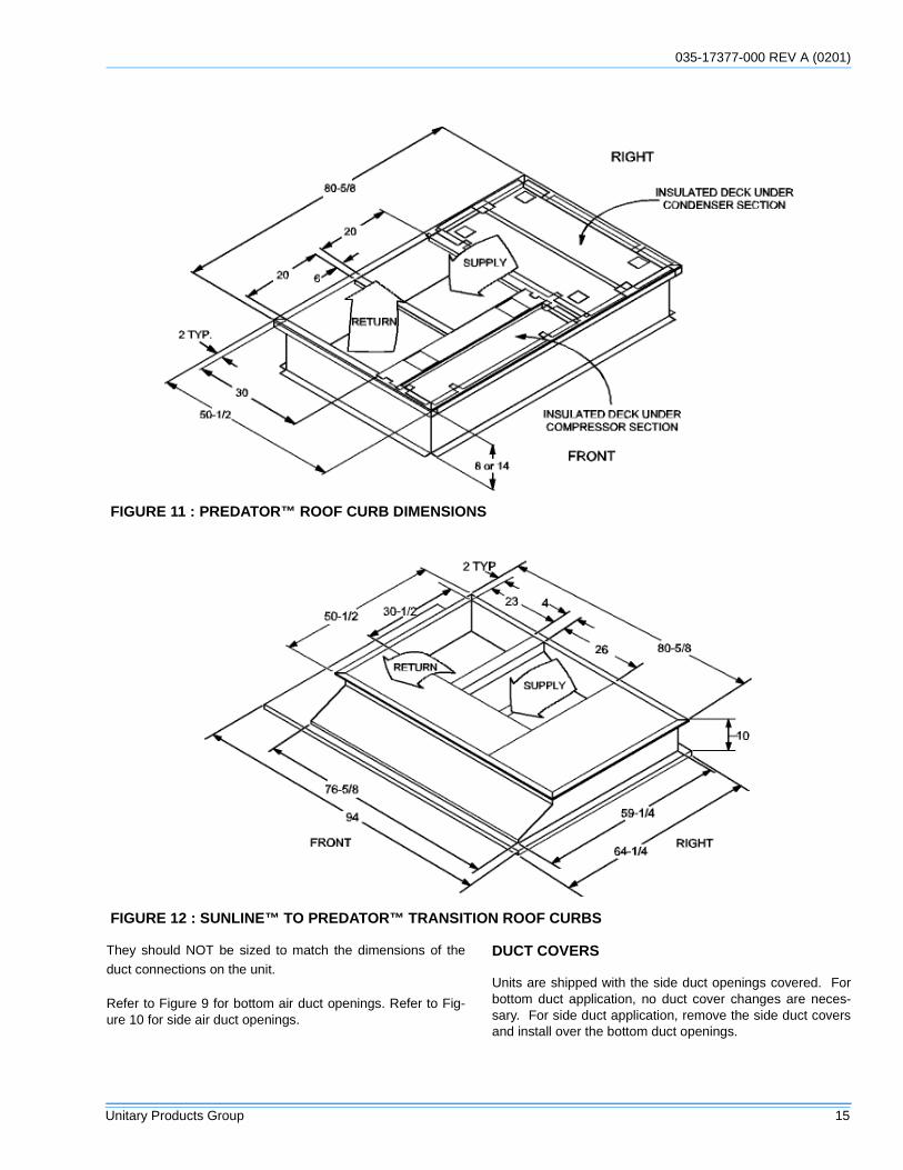
FIGURE 11 : PREDATOR™ ROOF CURB DIMENSIONS
FIGURE 12 : SUNLINE™ TO PREDATOR™ TRANSITION ROOF CURBS
035-17377-000 (0201) REV A
16 Unitary Products Group
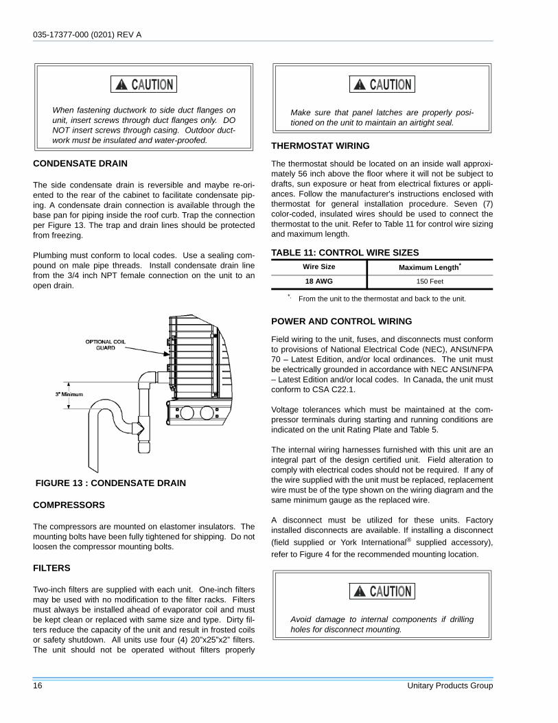
CONDENSATE DRAIN
The side condensate drain is reversible and maybe re-ori-ented to the rear of the cabinet to facilitate condensate pip-ing. A condensate drain connection is available through thebase pan for piping inside the roof curb. Trap the connectionper Figure 13. The trap and drain lines should be protectedfrom freezing.
Plumbing must conform to local codes. Use a sealing com-pound on male pipe threads. Install condensate drain linefrom the 3/4 inch NPT female connection on the unit to anopen drain.
COMPRESSORS
The compressors are mounted on elastomer insulators. Themounting bolts have been fully tightened for shipping. Do notloosen the compressor mounting bolts.
FILTERS
Two-inch filters are supplied with each unit. One-inch filtersmay be used with no modification to the filter racks. Filtersmust always be installed ahead of evaporator coil and mustbe kept clean or replaced with same size and type. Dirty fil-ters reduce the capacity of the unit and result in frosted coilsor safety shutdown. All units use four (4) 20”x25”x2” filters.The unit should not be operated without filters properly
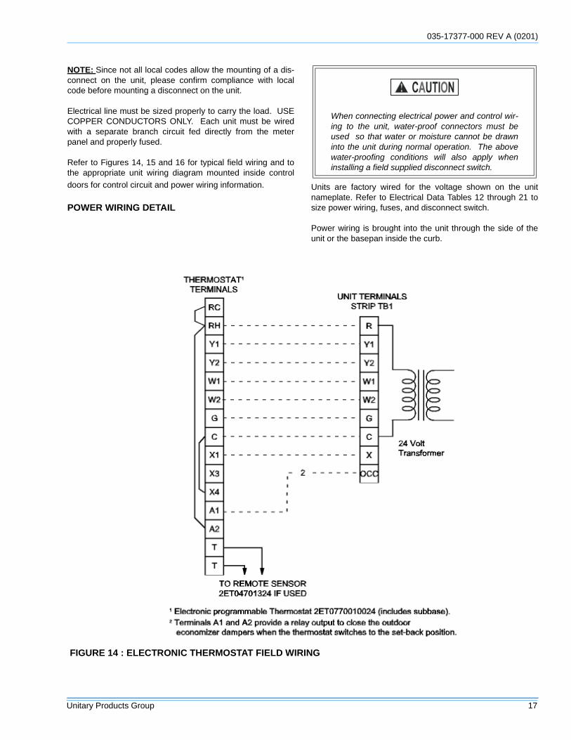
THERMOSTAT WIRING
The thermostat should be located on an inside wall approxi-mately 56 inch above the floor where it will not be subject todrafts, sun exposure or heat from electrical fixtures or appli-ances. Follow the manufacturer's instructions enclosed withthermostat for general installation procedure. Seven (7)color-coded, insulated wires should be used to connect thethermostat to the unit. Refer to Table 11 for control wire sizingand maximum length.
POWER AND CONTROL WIRING
Field wiring to the unit, fuses, and disconnects must conformto provisions of National Electrical Code (NEC), ANSI/NFPA70 – Latest Edition, and/or local ordinances. The unit mustbe electrically grounded in accordance with NEC ANSI/NFPA– Latest Edition and/or local codes. In Canada, the unit mustconform to CSA C22.1.
Voltage tolerances which must be maintained at the com-pressor terminals during starting and running conditions areindicated on the unit Rating Plate and Table 5.
The internal wiring harnesses furnished with this unit are anintegral part of the design certified unit. Field alteration tocomply with electrical codes should not be required. If any ofthe wire supplied with the unit must be replaced, replacementwire must be of the type shown on the wiring diagram and thesame minimum gauge as the replaced wire.
A disconnect must be utilized for these units. Factoryinstalled disconnects are available. If installing a disconnect
(field supplied or York International supplied accessory),
refer to Figure 4 for the recommended mounting location.
When fastening ductwork to side duct flanges onunit, insert screws through duct flanges only. DONOT insert screws through casing. Outdoor duct-work must be insulated and water-proofed.
FIGURE 13 : CONDENSATE DRAIN
Make sure that panel latches are properly posi-tioned on the unit to maintain an airtight seal.
TABLE 11: CONTROL WIRE SIZESWire Size Maximum Length*
*. From the unit to the thermostat and back to the unit.
18 AWG 150 Feet
Avoid damage to internal components if drillingholes for disconnect mounting.
035-17377-000 REV A (0201)
Unitary Products Group 17
NOTE: Since not all local codes allow the mounting of a dis-connect on the unit, please confirm compliance with localcode before mounting a disconnect on the unit.
Electrical line must be sized properly to carry the load. USECOPPER CONDUCTORS ONLY. Each unit must be wiredwith a separate branch circuit fed directly from the meterpanel and properly fused.
Refer to Figures 14, 15 and 16 for typical field wiring and tothe appropriate unit wiring diagram mounted inside controldoors for control circuit and power wiring information.
POWER WIRING DETAIL
Units are factory wired for the voltage shown on the unitnameplate. Refer to Electrical Data Tables 12 through 21 tosize power wiring, fuses, and disconnect switch.
Power wiring is brought into the unit through the side of theunit or the basepan inside the curb.
When connecting electrical power and control wir-ing to the unit, water-proof connectors must beused so that water or moisture cannot be drawninto the unit during normal operation. The abovewater-proofing conditions will also apply wheninstalling a field supplied disconnect switch.
FIGURE 14 : ELECTRONIC THERMOSTAT FIELD WIRING
035-17377-000 (0201) REV A
18 Unitary Products Group
FIGURE 15 : FIELD WIRING 24 VOLT THERMOSTAT
035-17377-000 REV A (0201)
Unitary Products Group 19
FIGURE 16 : FIELD WIRING DISCONNECTTABLE 12: ELECTRICAL DATA 6-1/2 TON - STANDARD EFFICIENCY
VoltageCompressors OD Fan
MotorsFLA ea.
Blower Motor SupplyFLA
Electric HeaterMin. CircuitAmpacity(Amps)
Max Fuse*
Size (Amps)
RLAea.
LRAea.
1.5 HP 2 HPModel
NumbersRated
kWHeaterAmps
1.5 HP 2 HP 1.5 HP 2 HP
208 14.1 110 1.5 6.2 8.2
None - - 40.9 42.9 50 50
2TP04510925 6.8 18.7 40.9 42.9 50 50
2TP04511825 13.5 37.5 54.6 57.1 60 60
2TP04512425 18.0 50.0 70.2 72.7 80 80
2TP04513625 27.0 70.8 96.2 98.7 100 100
230 14.1 110 1.5 6.2 8.2
None - - 40.9 42.9 50 50
2TP04510925 9.0 21.7 40.9 42.9 50 50
2TP04511825 18.0 43.3 61.9 64.4 70 70
2TP04512425 24.0 57.7 79.9 82.4 80 90
2TP04513625 34.0 81.8 110.0 112.5 110 125
460 7.1 54 0.8 3.1 4.1
None - - 20.7 21.7 25 25
2TP04510946 9.0 10.8 20.7 21.7 25 25
2TP04511846 18.0 21.7 30.9 32.2 35 35
2TP04512446 24.0 28.9 40.0 41.2 40 45
2TP04513646 34.0 40.9 55.0 56.2 60 60
575 5.8 44 0.6 2.4 3.6
None - - 16.7 17.9 20 20
2TP04510958 9.0 8.7 16.7 17.9 20 20
2TP04511858 18.0 17.3 24.7 26.2 25 30
2TP04512458 24.0 23.1 31.9 33.4 35 35
2TP04513658 34.0 32.7 43.9 45.4 45 50
*. Maximum HACR breaker of the same AMP size is applicable.
035-17377-000 (0201) REV A
20 Unitary Products Group
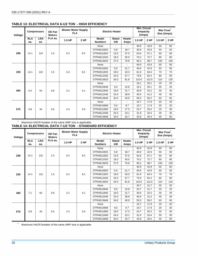
TABLE 13: ELECTRICAL DATA 6-1/2 TON - HIGH EFFICIENCY
VoltageCompressors OD Fan
MotorsFLA ea.
Blower Motor SupplyFLA
Electric HeaterMin. CircuitAmpacity(Amps)
Max Fuse*
Size (Amps)
RLAea.
LRAea.
1.5 HP 2 HPModel
NumbersRated
kWHeaterAmps
1.5 HP 2 HP 1.5 HP 2 HP
208 14.1 110 1.5 6.2 8.2
None - - 40.9 42.9 50 50
2TP04510925 6.8 18.7 40.9 42.9 50 50
2TP04511825 13.5 37.5 54.6 57.1 60 60
2TP04512425 18.0 50.0 70.2 72.7 80 80
2TP04513625 27.0 70.8 96.2 98.7 100 100
230 14.1 110 1.5 6.2 8.2
None - - 40.9 42.9 50 50
2TP04510925 9.0 21.7 40.9 42.9 50 50
2TP04511825 18.0 43.3 61.9 64.4 70 70
2TP04512425 24.0 57.7 79.9 82.4 80 90
2TP04513625 34.0 81.8 110.0 112.5 110 125
460 6.4 54 0.8 3.1 4.1
None - - 19.1 20.1 25 25
2TP04510946 9.0 10.8 19.1 20.1 25 25
2TP04511846 18.0 21.7 30.9 32.2 35 35
2TP04512446 24.0 28.9 40.0 41.2 40 45
2TP04513646 34.0 40.9 55.0 56.2 60 60
575 5.8 44 0.6 2.4 3.6
None - - 16.7 17.9 20 20
2TP04510958 9.0 8.7 16.7 17.9 20 20
2TP04511858 18.0 17.3 24.7 26.2 25 30
2TP04512458 24.0 23.1 31.9 33.4 35 35
2TP04513658 34.0 32.7 43.9 45.4 45 50
*. Maximum HACR breaker of the same AMP size is applicable.
TABLE 14: ELECTRICAL DATA 7-1/2 TON - STANDARD EFFICIENCY
VoltageCompressors OD Fan
MotorsFLA ea.
Blower Motor SupplyFLA
Electric HeaterMin. CircuitAmpacity(Amps)
Max Fuse*
Size (Amps)
RLAea.
LRAea.
1.5 HP 2 HPModel
NumbersRated
kWHeaterAmps
1.5 HP 2 HP 1.5 HP 2 HP
208 14.1 110 1.5 6.2 8.2
None - - 40.9 42.9 50 50
2TP04510925 6.8 18.7 40.9 42.9 50 50
2TP04511825 13.5 37.5 54.6 57.1 60 60
2TP04512425 18.0 50.0 70.2 72.7 80 80
2TP04513625 27.0 70.8 96.2 98.7 100 100
230 14.1 110 1.5 6.2 8.2
None - - 40.9 42.9 50 50
2TP04510925 9.0 21.7 40.9 42.9 50 50
2TP04511825 18.0 43.3 61.9 64.4 70 70
2TP04512425 24.0 57.7 79.9 82.4 80 90
2TP04513625 34.0 81.8 110.0 112.5 110 125
460 7.1 64 0.8 3.1 4.1
None - - 20.7 21.7 25 25
2TP04510946 9.0 10.8 20.7 21.7 25 25
2TP04511846 18.0 21.7 30.9 32.2 35 35
2TP04512446 24.0 28.9 40.0 41.2 40 45
2TP04513646 34.0 40.9 55.0 56.2 60 60
575 5.8 44 0.6 2.4 3.6
None - - 16.7 17.9 20 20
2TP04510958 9.0 8.7 16.7 17.9 20 20
2TP04511858 18.0 17.3 24.7 26.2 25 30
2TP04512458 24.0 23.1 31.9 33.4 35 35
2TP04513658 34.0 32.7 43.9 45.4 45 50
*. Maximum HACR breaker of the same AMP size is applicable.
035-17377-000 REV A (0201)
Unitary Products Group 21
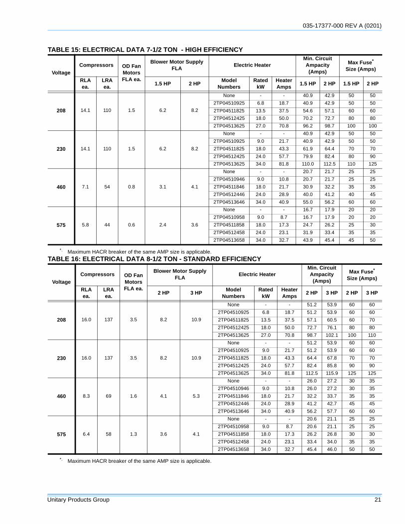
TABLE 15: ELECTRICAL DATA 7-1/2 TON - HIGH EFFICIENCY
VoltageCompressors OD Fan
MotorsFLA ea.
Blower Motor SupplyFLA
Electric HeaterMin. CircuitAmpacity(Amps)
Max Fuse*
Size (Amps)
RLAea.
LRAea.
1.5 HP 2 HPModel
NumbersRated
kWHeaterAmps
1.5 HP 2 HP 1.5 HP 2 HP
208 14.1 110 1.5 6.2 8.2
None - - 40.9 42.9 50 50
2TP04510925 6.8 18.7 40.9 42.9 50 50
2TP04511825 13.5 37.5 54.6 57.1 60 60
2TP04512425 18.0 50.0 70.2 72.7 80 80
2TP04513625 27.0 70.8 96.2 98.7 100 100
230 14.1 110 1.5 6.2 8.2
None - - 40.9 42.9 50 50
2TP04510925 9.0 21.7 40.9 42.9 50 50
2TP04511825 18.0 43.3 61.9 64.4 70 70
2TP04512425 24.0 57.7 79.9 82.4 80 90
2TP04513625 34.0 81.8 110.0 112.5 110 125
460 7.1 54 0.8 3.1 4.1
None - - 20.7 21.7 25 25
2TP04510946 9.0 10.8 20.7 21.7 25 25
2TP04511846 18.0 21.7 30.9 32.2 35 35
2TP04512446 24.0 28.9 40.0 41.2 40 45
2TP04513646 34.0 40.9 55.0 56.2 60 60
575 5.8 44 0.6 2.4 3.6
None - - 16.7 17.9 20 20
2TP04510958 9.0 8.7 16.7 17.9 20 20
2TP04511858 18.0 17.3 24.7 26.2 25 30
2TP04512458 24.0 23.1 31.9 33.4 35 35
2TP04513658 34.0 32.7 43.9 45.4 45 50
*. Maximum HACR breaker of the same AMP size is applicable.TABLE 16: ELECTRICAL DATA 8-1/2 TON - STANDARD EFFICIENCY
VoltageCompressors OD Fan
MotorsFLA ea.
Blower Motor SupplyFLA
Electric HeaterMin. CircuitAmpacity(Amps)
Max Fuse*
Size (Amps)
RLAea.
LRAea.
2 HP 3 HPModel
NumbersRated
kWHeaterAmps
2 HP 3 HP 2 HP 3 HP
208 16.0 137 3.5 8.2 10.9
None - - 51.2 53.9 60 60
2TP04510925 6.8 18.7 51.2 53.9 60 60
2TP04511825 13.5 37.5 57.1 60.5 60 70
2TP04512425 18.0 50.0 72.7 76.1 80 80
2TP04513625 27.0 70.8 98.7 102.1 100 110
230 16.0 137 3.5 8.2 10.9
None - - 51.2 53.9 60 60
2TP04510925 9.0 21.7 51.2 53.9 60 60
2TP04511825 18.0 43.3 64.4 67.8 70 70
2TP04512425 24.0 57.7 82.4 85.8 90 90
2TP04513625 34.0 81.8 112.5 115.9 125 125
460 8.3 69 1.6 4.1 5.3
None - - 26.0 27.2 30 35
2TP04510946 9.0 10.8 26.0 27.2 30 35
2TP04511846 18.0 21.7 32.2 33.7 35 35
2TP04512446 24.0 28.9 41.2 42.7 45 45
2TP04513646 34.0 40.9 56.2 57.7 60 60
575 6.4 58 1.3 3.6 4.1
None - - 20.6 21.1 25 25
2TP04510958 9.0 8.7 20.6 21.1 25 25
2TP04511858 18.0 17.3 26.2 26.8 30 30
2TP04512458 24.0 23.1 33.4 34.0 35 35
2TP04513658 34.0 32.7 45.4 46.0 50 50
*. Maximum HACR breaker of the same AMP size is applicable.
035-17377-000 (0201) REV A
22 Unitary Products Group
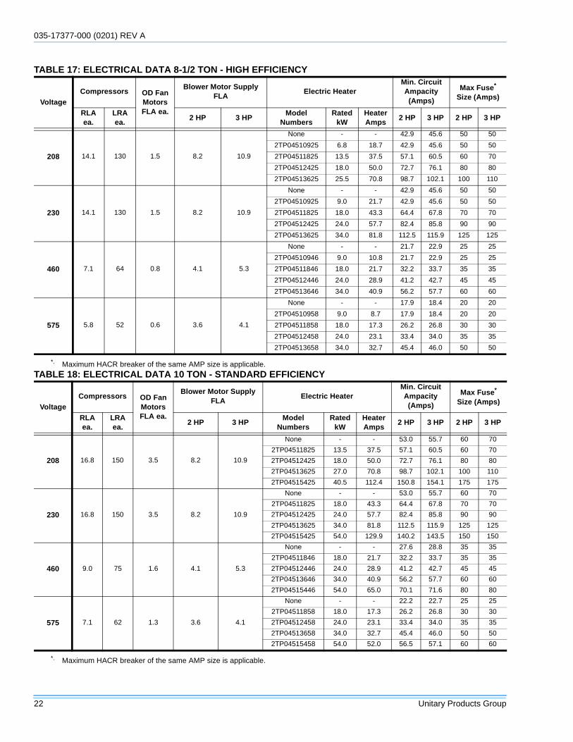
TABLE 17: ELECTRICAL DATA 8-1/2 TON - HIGH EFFICIENCY
VoltageCompressors OD Fan
MotorsFLA ea.
Blower Motor SupplyFLA
Electric HeaterMin. CircuitAmpacity(Amps)
Max Fuse*
Size (Amps)
RLAea.
LRAea.
2 HP 3 HPModel
NumbersRated
kWHeaterAmps
2 HP 3 HP 2 HP 3 HP
208 14.1 130 1.5 8.2 10.9
None - - 42.9 45.6 50 50
2TP04510925 6.8 18.7 42.9 45.6 50 50
2TP04511825 13.5 37.5 57.1 60.5 60 70
2TP04512425 18.0 50.0 72.7 76.1 80 80
2TP04513625 25.5 70.8 98.7 102.1 100 110
230 14.1 130 1.5 8.2 10.9
None - - 42.9 45.6 50 50
2TP04510925 9.0 21.7 42.9 45.6 50 50
2TP04511825 18.0 43.3 64.4 67.8 70 70
2TP04512425 24.0 57.7 82.4 85.8 90 90
2TP04513625 34.0 81.8 112.5 115.9 125 125
460 7.1 64 0.8 4.1 5.3
None - - 21.7 22.9 25 25
2TP04510946 9.0 10.8 21.7 22.9 25 25
2TP04511846 18.0 21.7 32.2 33.7 35 35
2TP04512446 24.0 28.9 41.2 42.7 45 45
2TP04513646 34.0 40.9 56.2 57.7 60 60
575 5.8 52 0.6 3.6 4.1
None - - 17.9 18.4 20 20
2TP04510958 9.0 8.7 17.9 18.4 20 20
2TP04511858 18.0 17.3 26.2 26.8 30 30
2TP04512458 24.0 23.1 33.4 34.0 35 35
2TP04513658 34.0 32.7 45.4 46.0 50 50
*. Maximum HACR breaker of the same AMP size is applicable.TABLE 18: ELECTRICAL DATA 10 TON - STANDARD EFFICIENCY
VoltageCompressors OD Fan
MotorsFLA ea.
Blower Motor SupplyFLA
Electric HeaterMin. CircuitAmpacity(Amps)
Max Fuse*
Size (Amps)
RLAea.
LRAea.
2 HP 3 HPModel
NumbersRated
kWHeaterAmps
2 HP 3 HP 2 HP 3 HP
208 16.8 150 3.5 8.2 10.9
None - - 53.0 55.7 60 70
2TP04511825 13.5 37.5 57.1 60.5 60 70
2TP04512425 18.0 50.0 72.7 76.1 80 80
2TP04513625 27.0 70.8 98.7 102.1 100 110
2TP04515425 40.5 112.4 150.8 154.1 175 175
230 16.8 150 3.5 8.2 10.9
None - - 53.0 55.7 60 70
2TP04511825 18.0 43.3 64.4 67.8 70 70
2TP04512425 24.0 57.7 82.4 85.8 90 90
2TP04513625 34.0 81.8 112.5 115.9 125 125
2TP04515425 54.0 129.9 140.2 143.5 150 150
460 9.0 75 1.6 4.1 5.3
None - - 27.6 28.8 35 35
2TP04511846 18.0 21.7 32.2 33.7 35 35
2TP04512446 24.0 28.9 41.2 42.7 45 45
2TP04513646 34.0 40.9 56.2 57.7 60 60
2TP04515446 54.0 65.0 70.1 71.6 80 80
575 7.1 62 1.3 3.6 4.1
None - - 22.2 22.7 25 25
2TP04511858 18.0 17.3 26.2 26.8 30 30
2TP04512458 24.0 23.1 33.4 34.0 35 35
2TP04513658 34.0 32.7 45.4 46.0 50 50
2TP04515458 54.0 52.0 56.5 57.1 60 60
*. Maximum HACR breaker of the same AMP size is applicable.
035-17377-000 REV A (0201)
Unitary Products Group 23
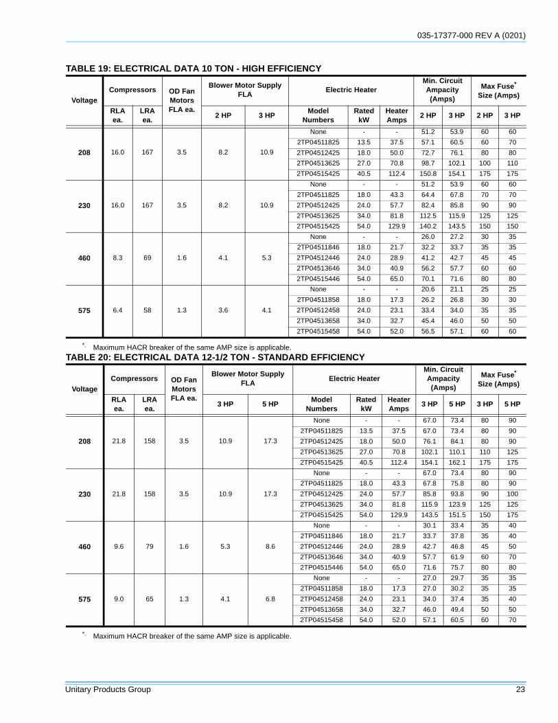
TABLE 19: ELECTRICAL DATA 10 TON - HIGH EFFICIENCY
VoltageCompressors OD Fan
MotorsFLA ea.
Blower Motor SupplyFLA
Electric HeaterMin. CircuitAmpacity(Amps)
Max Fuse*
Size (Amps)
RLAea.
LRAea.
2 HP 3 HPModel
NumbersRated
kWHeaterAmps
2 HP 3 HP 2 HP 3 HP
208 16.0 167 3.5 8.2 10.9
None - - 51.2 53.9 60 60
2TP04511825 13.5 37.5 57.1 60.5 60 70
2TP04512425 18.0 50.0 72.7 76.1 80 80
2TP04513625 27.0 70.8 98.7 102.1 100 110
2TP04515425 40.5 112.4 150.8 154.1 175 175
230 16.0 167 3.5 8.2 10.9
None - - 51.2 53.9 60 60
2TP04511825 18.0 43.3 64.4 67.8 70 70
2TP04512425 24.0 57.7 82.4 85.8 90 90
2TP04513625 34.0 81.8 112.5 115.9 125 125
2TP04515425 54.0 129.9 140.2 143.5 150 150
460 8.3 69 1.6 4.1 5.3
None - - 26.0 27.2 30 35
2TP04511846 18.0 21.7 32.2 33.7 35 35
2TP04512446 24.0 28.9 41.2 42.7 45 45
2TP04513646 34.0 40.9 56.2 57.7 60 60
2TP04515446 54.0 65.0 70.1 71.6 80 80
575 6.4 58 1.3 3.6 4.1
None - - 20.6 21.1 25 25
2TP04511858 18.0 17.3 26.2 26.8 30 30
2TP04512458 24.0 23.1 33.4 34.0 35 35
2TP04513658 34.0 32.7 45.4 46.0 50 50
2TP04515458 54.0 52.0 56.5 57.1 60 60
*. Maximum HACR breaker of the same AMP size is applicable.TABLE 20: ELECTRICAL DATA 12-1/2 TON - STANDARD EFFICIENCY
VoltageCompressors OD Fan
MotorsFLA ea.
Blower Motor SupplyFLA
Electric HeaterMin. CircuitAmpacity(Amps)
Max Fuse*
Size (Amps)
RLAea.
LRAea.
3 HP 5 HPModel
NumbersRated
kWHeaterAmps
3 HP 5 HP 3 HP 5 HP
208 21.8 158 3.5 10.9 17.3
None - - 67.0 73.4 80 90
2TP04511825 13.5 37.5 67.0 73.4 80 90
2TP04512425 18.0 50.0 76.1 84.1 80 90
2TP04513625 27.0 70.8 102.1 110.1 110 125
2TP04515425 40.5 112.4 154.1 162.1 175 175
230 21.8 158 3.5 10.9 17.3
None - - 67.0 73.4 80 90
2TP04511825 18.0 43.3 67.8 75.8 80 90
2TP04512425 24.0 57.7 85.8 93.8 90 100
2TP04513625 34.0 81.8 115.9 123.9 125 125
2TP04515425 54.0 129.9 143.5 151.5 150 175
460 9.6 79 1.6 5.3 8.6
None - - 30.1 33.4 35 40
2TP04511846 18.0 21.7 33.7 37.8 35 40
2TP04512446 24.0 28.9 42.7 46.8 45 50
2TP04513646 34.0 40.9 57.7 61.9 60 70
2TP04515446 54.0 65.0 71.6 75.7 80 80
575 9.0 65 1.3 4.1 6.8
None - - 27.0 29.7 35 35
2TP04511858 18.0 17.3 27.0 30.2 35 35
2TP04512458 24.0 23.1 34.0 37.4 35 40
2TP04513658 34.0 32.7 46.0 49.4 50 50
2TP04515458 54.0 52.0 57.1 60.5 60 70
*. Maximum HACR breaker of the same AMP size is applicable.
035-17377-000 (0201) REV A
24 Unitary Products Group
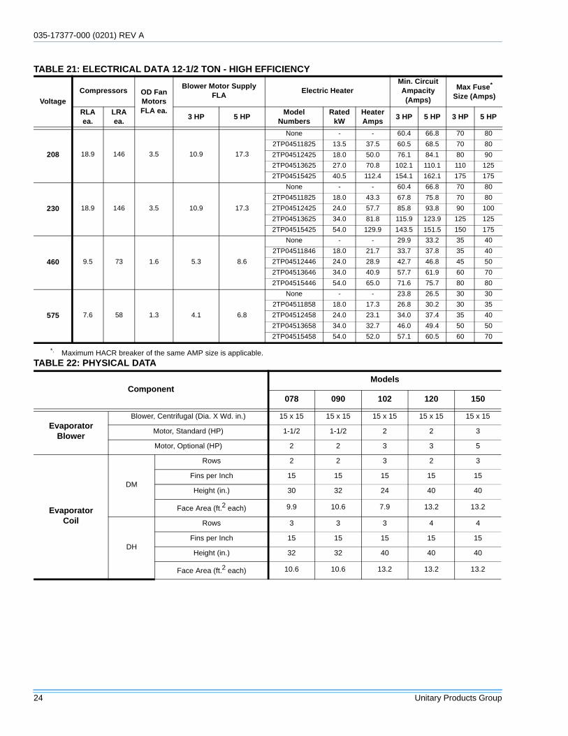
TABLE 21: ELECTRICAL DATA 12-1/2 TON - HIGH EFFICIENCY
VoltageCompressors OD Fan
MotorsFLA ea.
Blower Motor SupplyFLA
Electric HeaterMin. CircuitAmpacity(Amps)
Max Fuse*
Size (Amps)
RLAea.
LRAea.
3 HP 5 HPModel
NumbersRated
kWHeaterAmps
3 HP 5 HP 3 HP 5 HP
208 18.9 146 3.5 10.9 17.3
None - - 60.4 66.8 70 80
2TP04511825 13.5 37.5 60.5 68.5 70 80
2TP04512425 18.0 50.0 76.1 84.1 80 90
2TP04513625 27.0 70.8 102.1 110.1 110 125
2TP04515425 40.5 112.4 154.1 162.1 175 175
230 18.9 146 3.5 10.9 17.3
None - - 60.4 66.8 70 80
2TP04511825 18.0 43.3 67.8 75.8 70 80
2TP04512425 24.0 57.7 85.8 93.8 90 100
2TP04513625 34.0 81.8 115.9 123.9 125 125
2TP04515425 54.0 129.9 143.5 151.5 150 175
460 9.5 73 1.6 5.3 8.6
None - - 29.9 33.2 35 40
2TP04511846 18.0 21.7 33.7 37.8 35 40
2TP04512446 24.0 28.9 42.7 46.8 45 50
2TP04513646 34.0 40.9 57.7 61.9 60 70
2TP04515446 54.0 65.0 71.6 75.7 80 80
575 7.6 58 1.3 4.1 6.8
None - - 23.8 26.5 30 30
2TP04511858 18.0 17.3 26.8 30.2 30 35
2TP04512458 24.0 23.1 34.0 37.4 35 40
2TP04513658 34.0 32.7 46.0 49.4 50 50
2TP04515458 54.0 52.0 57.1 60.5 60 70
*. Maximum HACR breaker of the same AMP size is applicable.TABLE 22: PHYSICAL DATA
ComponentModels
078 090 102 120 150
EvaporatorBlower
Blower, Centrifugal (Dia. X Wd. in.) 15 x 15 15 x 15 15 x 15 15 x 15 15 x 15
Motor, Standard (HP) 1-1/2 1-1/2 2 2 3
Motor, Optional (HP) 2 2 3 3 5
EvaporatorCoil
DM
Rows 2 2 3 2 3
Fins per Inch 15 15 15 15 15
Height (in.) 30 32 24 40 40
Face Area (ft.2 each) 9.9 10.6 7.9 13.2 13.2
DH
Rows 3 3 3 4 4
Fins per Inch 15 15 15 15 15
Height (in.) 32 32 40 40 40
Face Area (ft.2 each) 10.6 10.6 13.2 13.2 13.2
035-17377-000 REV A (0201)
Unitary Products Group 25
CondenserFan
(2 per Unit)
DM
Propeller Dia. (in., each) 24 24 24 24 24
Motor (HP, each) 1/3 1/3 3/4 3/4 3/4
CFM, Nominal (each) 3400 3400 4400 4400 4400
DH
Propeller Dia. (in., each) 24 24 24 24 24
Motor (HP, each) 1/3 1/3 1/3 3/4 3/4
CFM, Nominal (each) 3400 3400 3400 4400 4400
CondenserCoil
(2 per unit)
DM
Rows (each) 1 1 1 1 2
Fins per Inch 20 20 20 20 20
Height (in. each) 24 28 36 44 44
Face Area (ft.2 each) 7.9 9.2 11.9 14.5 14.5
DH
Rows (each) 1 1 2 2 2
Fins per Inch 20 20 20 20 20
Height (in., each) 44 44 44 44 44
Face Area (ft.2 each) 14.5 14.5 14.5 14.5 14.5
RefrigerantCharge
DMSystem 1 (lb./oz.) 4/6 4/12 5/0 6/12 10/12
System 2 (lb./oz.) 4/0 4/6 5/4 6/12 9/8
DHSystem 1 (lb./oz.) 6/4 6/14 10/0 12/0 9/14
System 2 (lb./oz.) 5/12 6/8 9/8 11/0 9/4
Compressors
DMQuantity 2 2 2 2 2
Type Recip Recip Recip Recip Recip
DHQuantity 2 2 2 2 2
Type Recip Recip Recip Recip Scroll
Air FiltersSize (Wd. x Ht. x Thickness in.) 25x20x2 25x20x2 25x20x2 25x20x2 25x20x2
Number Per Unit 4 4 4 4 4
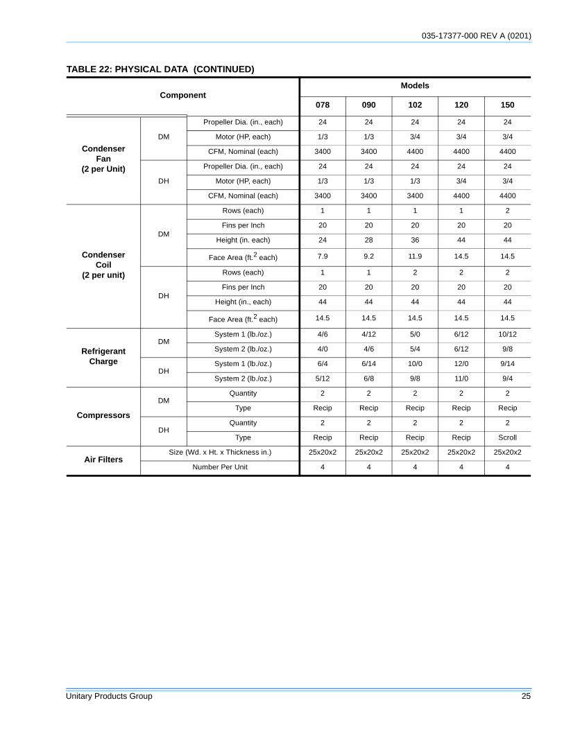
TABLE 22: PHYSICAL DATA (CONTINUED)
ComponentModels
078 090 102 120 150
035-17377-000 (0201) REV A
26 Unitary Products Group
GAS HEAT
LP UNITS, TANKS AND PIPING
All gas heat units are shipped from the factory equipped fornatural gas use only. The unit may be converted in the fieldfor use with LP gas with accessory kit model number1NP0441.
All LP gas equipment must conform to the safety standards ofthe National Fire Protection Association.
For satisfactory operation, LP gas pressure must be 10.5inch W.C. at the unit under full load. Maintaining proper gaspressure depends on three main factors:
1. The vaporization rate which depends on the temperature of the liquid and the “wetted surface” area of the con-tainer(s).
2. The proper pressure regulation. (Two-stage regulation is recommended).
3. The pressure drop in the lines between regulators and between the second stage regulator and the appliance. Pipe size required will depend on the length of the pipe run and the total load of all appliances.
Complete information regarding tank sizing for vaporization,recommended regulator settings, and pipe sizing is availablefrom most regulator manufacturers and LP gas suppliers.
LP gas is an excellent solvent and will quickly dissolve whitelead and most standard commercial compounds. A specialpipe dope must be used when assembling wrought iron orsteel pipe for LP. Shellac base compounds such as Gaskolacor Stalastic, and compounds such as Rectorseal #5, Clyde’s,or John Crane may be used.
GAS PIPING
Proper sizing of gas piping depends on the cubic feet perhour of gas flow required, specific gravity of the gas, and thelength of run. National Fuel Gas Code, ANSI Z223.1 - LatestEdition should be followed in all cases unless superseded bylocal codes or gas company requirements. Refer to Table 24.The heating value of the gas may differ with locality. Thevalue should be checked with the local gas utility. In Canadaplease refer to the Natural Gas and Propane InstallationCode CSA - B149.
TABLE 23: GAS HEAT LIMIT SETTINGS*
*. Rollout = 300°F, Auxiliary Limit = 200°F
# of HX Tubes Main Limit Setting
4 215°F
6 195°F
8 160°F
FIGURE 17 : SIDE ENTRY GAS PIPING
FIGURE 18 : BOTTOM ENTRY GAS PIPING
OPTIONALCOILGUARDSHOWN
035-17377-000 REV A (0201)
Unitary Products Group 27
NOTE: Maximum capacity of pipe in cubic feet of gas perhour based upon a pressure drop of 0.3 inch W.C. and 0.6specific gravity gas.
NOTE: There may be a local gas utility requirement specify-ing a minimum diameter for gas piping. All units require a 3/4inch pipe connection at the entrance fitting. Line should notbe sized smaller than the entrance fitting size.
GAS CONNECTION
The gas supply line can be routed within the space and roofcurb, exiting through the unit’s basepan. Refer to Figure 9 forthe gas piping inlet location. Typical supply piping arrange-ments are shown in Figures 17 and 18. All pipe nipples, fit-tings, and the gas cock are field supplied or may bepurchased in UPG accessory kit #1GP0404.
Gas piping recommendations:
1. A drip leg and a ground joint union must be installed in the gas piping.
2. Where required by local codes, a manual shut-off valve must be installed outside of the unit.
3. Use wrought iron or steel pipe for all gas lines. Pipe dope should be applied sparingly to male threads only.
4. All piping should be cleaned of dirt and scale by ham-mering on the outside of the pipe and blowing out loose particles. Before initial start-up, be sure that all gas lines external to the unit have been purged of air.
5. The gas supply should be a separate line and installed in accordance with all safety codes as prescribed under “Limitations”.
6. A 1/8-inch NPT plugged tapping, accessible for test gage connection, must be installed immediately upstream of the gas supply connection to the unit.
7. After the gas connections have been completed, open the main shut-off valve admitting normal gas pressure to the mains. Check all joints for leaks with soap solution or other material suitable for the purpose. NEVER USE A FLAME.
VENT AND COMBUSTION AIR
Venting slots in the heating compartment access panelremove the need for a combustion air hood. The gas heatflue exhaust is routed through factory installed exhaust pipingwith screen. If necessary, a flue exhaust extension may beinstalled at the point of installation.
ACCESSORIES
ELECTRIC HEAT
Electric heaters are available for field installation. Refer toelectric heat instructions for installation. These heatersmount in the heat compartment with the heating elementsextending into the supply air chamber. All electric heaters arefused and intended for use with single point power supply.
TABLE 24: GAS PIPE SIZING - CAPACITY OF PIPE
Length of Pipe (ft.)
Nominal Iron Pipe Size
3/4 in. 1 in. 1-1/4 in.
10 278 520 1050
20 190 350 730
30 152 285 590
40 130 245 500
50 115 215 440
60 105 195 400
70 96 180 370
80 90 170 350
90 84 160 320
100 79 150 305
Natural gas may contain some propane. Propaneis an excellent solvent and will quickly dissolvewhite lead and most standard commercial com-pounds. A special pipe dope must be used whenassembling wrought iron or steel pipe. Shellacbased compounds such as Gaskolac or Stalastic,and compounds such as Rectorseal #5, Clydes’sor John Crane may be used.
The furnace and its individual shut-off valve mustbe disconnected from the gas supply piping sys-tem during any pressure testing at pressures inexcess of 1/2 PSIG.
Pressures greater than 1/2 PSIG will cause gasvalve damage resulting in a hazardous condition.If it is subjected to a pressure greater than 1/2PSIG, the gas valve must be replace.
The furnace must be isolated from the gas supplypiping system by closing its individual manualshut-off valve during any pressure testing of thegas supply piping system at test pressures equalto or less than 1/2 PSIG.
035-17377-000 (0201) REV A
28 Unitary Products Group
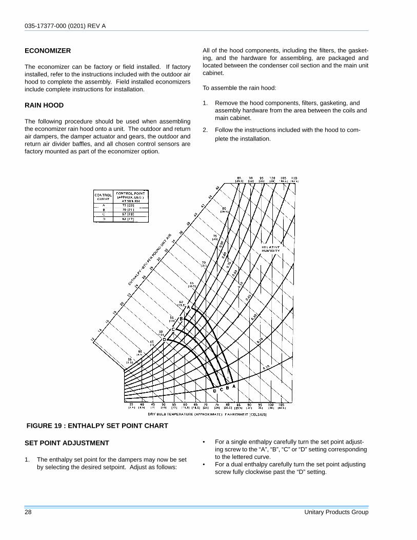
ECONOMIZER
The economizer can be factory or field installed. If factoryinstalled, refer to the instructions included with the outdoor airhood to complete the assembly. Field installed economizersinclude complete instructions for installation.
RAIN HOOD
The following procedure should be used when assemblingthe economizer rain hood onto a unit. The outdoor and returnair dampers, the damper actuator and gears, the outdoor andreturn air divider baffles, and all chosen control sensors arefactory mounted as part of the economizer option.
All of the hood components, including the filters, the gasket-ing, and the hardware for assembling, are packaged andlocated between the condenser coil section and the main unitcabinet.
To assemble the rain hood:
1. Remove the hood components, filters, gasketing, and assembly hardware from the area between the coils and main cabinet.
2. Follow the instructions included with the hood to com-plete the installation.
SET POINT ADJUSTMENT
1. The enthalpy set point for the dampers may now be set by selecting the desired setpoint. Adjust as follows:
• For a single enthalpy carefully turn the set point adjust-ing screw to the “A”, “B”, “C” or “D” setting corresponding to the lettered curve.
• For a dual enthalpy carefully turn the set point adjusting screw fully clockwise past the “D” setting.
FIGURE 19 : ENTHALPY SET POINT CHART
035-17377-000 REV A (0201)
Unitary Products Group 29
2. To check that the damper blades move smoothly without binding carefully turn the minimum position adjusting screw fully clockwise and then energize and de-energize terminals “R to “G”. With terminals “R” to “G” energized, turn the minimum position screw counterclockwise until the desired minimum position has been attained.
START-UP
PHASING
Predator units are properly phased at the factory. Check forproper compressor rotation. If the blower or compressorsrotate in the wrong direction at start-up, the electrical connec-tion to the unit is misphased. Change the incoming line con-nection phasing to obtain proper rotation. (Scrollcompressors operate in only one direction. If the scroll isdrawing low amperage, has similar suction and dischargepressures, or producing a high noise level, the scroll is mis-
phased).
SUPPLY AIR INSTRUCTIONS
CHECKING SUPPLY AIR CFM
The RPM of the supply air blower will depend on the requiredCFM, the static pressure resistances of the unit accessories(see Tables 25), and the static pressure resistance of the airduct system. With this information, the RPM for the supply airblower can be determined from the blower performance data(see Tables 27 - 46). Table 47 provides drive information forthe sheaves supplied with the unit.
The supply air CFM must be within the limitations shown inTable 26.
BLOWER ROTATION
Check for proper supply air blower rotation. If the blower isrotating backwards, the line voltage at the unit point of powerconnection is misphased (See ‘PHASING.’).
Extreme care must be exercised in turning boththe setpoint and minimum position adjustingscrews to prevent twisting them off.
TABLE 25: ACCESSORY STATIC RESISTANCE*
*. Deduct these resistance values from the available external static pressure shown in the respective Blower Performance Table.
Description
External Static Pressure Drop - Resistance, IWG
CFM
2250 3000 4000 5000 6000
Economizer 0.03 0.03 0.04 0.07 0.09
Scroll compressors require proper rotation to oper-ate correctly. Units are properly phased at the fac-tory. Do not change the internal wiring to make theblower condenser fans, or compressor rotate cor-rectly.
TABLE 26: SUPPLY AIR LIMITATIONSUnit Size Minimum Maximum
078 1950 3250
090 2250 3750
102 2550 4250
120 3000 5000
150 3750 6250
035-17377-000 (0201) REV A
30 Unitary Products Group
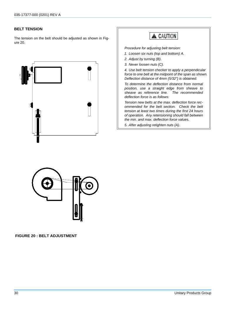
BELT TENSION
The tension on the belt should be adjusted as shown in Fig-ure 20.
FIGURE 20 : BELT ADJUSTMENT
Procedure for adjusting belt tension:
1. Loosen six nuts (top and bottom) A.
2. Adjust by turning (B).
3. Never loosen nuts (C).
4. Use belt tension checker to apply a perpendicular force to one belt at the midpoint of the span as shown. Deflection distance of 4mm (5/32”) is obtained.
To determine the deflection distance from normalposition, use a straight edge from sheave tosheave as reference line. The recommendeddeflection force is as follows:
Tension new belts at the max. deflection force rec-ommended for the belt section. Check the belttension at least two times during the first 24 hoursof operation. Any retensioning should fall betweenthe min. and max. deflection force values.
5. After adjusting retighten nuts (A).
035-17377-000 REV A (0201)
Unitary Products Group 31
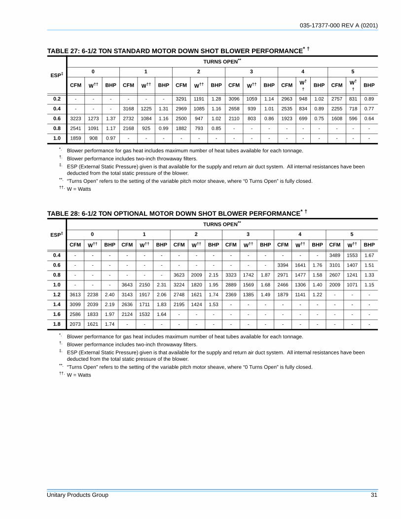
TABLE 27: 6-1/2 TON STANDARD MOTOR DOWN SHOT BLOWER PERFORMANCE* †
ESP‡
TURNS OPEN**
0 1 2 3 4 5
CFM W†† BHP CFM W†† BHP CFM W†† BHP CFM W†† BHP CFM W†
†BHP CFM W†
†BHP
0.2 - - - - - - 3291 1191 1.28 3096 1059 1.14 2963 948 1.02 2757 831 0.89
0.4 - - - 3168 1225 1.31 2969 1085 1.16 2658 939 1.01 2535 834 0.89 2255 718 0.77
0.6 3223 1273 1.37 2732 1084 1.16 2500 947 1.02 2110 803 0.86 1923 699 0.75 1608 596 0.64
0.8 2541 1091 1.17 2168 925 0.99 1882 793 0.85 - - - - - - - - -
1.0 1859 908 0.97 - - - - - - - - - - - - - - -
*. Blower performance for gas heat includes maximum number of heat tubes available for each tonnage.†. Blower performance includes two-inch throwaway filters.‡. ESP (External Static Pressure) given is that available for the supply and return air duct system. All internal resistances have been
deducted from the total static pressure of the blower.**. “Turns Open” refers to the setting of the variable pitch motor sheave, where “0 Turns Open” is fully closed.††. W = Watts
TABLE 28: 6-1/2 TON OPTIONAL MOTOR DOWN SHOT BLOWER PERFORMANCE* †
ESP‡
TURNS OPEN**
0 1 2 3 4 5
CFM W†† BHP CFM W†† BHP CFM W†† BHP CFM W†† BHP CFM W†† BHP CFM W†† BHP
0.4 - - - - - - - - - - - - - - - 3489 1553 1.67
0.6 - - - - - - - - - - - - 3394 1641 1.76 3101 1407 1.51
0.8 - - - - - - 3623 2009 2.15 3323 1742 1.87 2971 1477 1.58 2607 1241 1.33
1.0 - - - 3643 2150 2.31 3224 1820 1.95 2889 1569 1.68 2466 1306 1.40 2009 1071 1.15
1.2 3613 2238 2.40 3143 1917 2.06 2748 1621 1.74 2369 1385 1.49 1879 1141 1.22 - - -
1.4 3099 2039 2.19 2636 1711 1.83 2195 1424 1.53 - - - - - - - - -
1.6 2586 1833 1.97 2124 1532 1.64 - - - - - - - - - - - -
1.8 2073 1621 1.74 - - - - - - - - - - - - - - -
*. Blower performance for gas heat includes maximum number of heat tubes available for each tonnage.†. Blower performance includes two-inch throwaway filters.‡. ESP (External Static Pressure) given is that available for the supply and return air duct system. All internal resistances have been
deducted from the total static pressure of the blower.**. “Turns Open” refers to the setting of the variable pitch motor sheave, where “0 Turns Open” is fully closed.††. W = Watts
035-17377-000 (0201) REV A
32 Unitary Products Group
TABLE 29: 7-1/2 TON STANDARD MOTOR DOWN SHOT BLOWER PERFORMANCE* †
ESP‡
TURNS OPEN**
0 1 2 3 4 5
CFM W†† BHP CFM W†† BHP CFM W†† BHP CFM W†† BHP CFM W†
†BHP CFM W†
†BHP
0.2 - - - 3715 1573 1.69 3634 1434 1.54 3431 1265 1.36 3218 901 0.97 3024 976 1.05
0.4 3650 1657 1.78 3510 1490 1.60 3320 1313 1.41 3079 1145 1.23 2832 810 0.87 2586 860 0.92
0.6 3334 1522 1.63 3146 1351 1.45 2910 1169 1.25 2621 1005 1.08 2307 706 0.76 - - -
0.8 2903 1352 1.45 2622 1167 1.25 2404 1013 1.09 2054 858 0.92 - - - - - -
1.0 2356 1159 1.24 - - - - - - - - - - - - - - -
*. Blower performance for gas heat includes maximum number of heat tubes available for each tonnage.†. Blower performance includes two-inch throwaway filters.‡. ESP (External Static Pressure) given is that available for the supply and return air duct system. All internal resistances have been
deducted from the total static pressure of the blower.**. “Turns Open” refers to the setting of the variable pitch motor sheave, where “0 Turns Open” is fully closed.††. W = Watts
TABLE 30: 7-1/2 TON OPTIONAL MOTOR DOWN SHOT BLOWER PERFORMANCE* †
ESP‡
TURNS OPEN**
0 1 2 3 4 5
CFM W†† BHP CFM W†† BHP CFM W†† BHP CFM W†† BHP CFM W†† BHP CFM W†† BHP
0.2 - - - - - - - - - - - - 3992 1904 2.04 3798 1679 1.80
0.4 - - - - - - - - - 3930 2017 2.16 3734 1786 1.92 3486 1552 1.66
0.6 - - - - - - 3947 2176 2.33 3670 1895 2.03 3394 1641 1.76 3084 1401 1.50
0.8 - - - 4138 2384 2.56 3623 2009 2.15 3323 1742 1.87 2971 1477 1.58 2591 1236 1.33
1.0 4126 2430 2.61 3643 2145 2.30 3224 1820 1.95 2889 1569 1.68 2466 1306 1.40 - - -
1.2 3613 2238 2.40 3143 1921 2.06 2748 1621 1.74 2369 1385 1.49 - - - - - -
1.4 3099 2039 2.19 2636 1714 1.84 2195 1424 1.53 - - - - - - - - -
1.6 2586 1833 1.97 - - - - - - - - - - - - - - -
*. Blower performance for gas heat includes maximum number of heat tubes available for each tonnage.†. Blower performance includes two-inch throwaway filters.‡. ESP (External Static Pressure) given is that available for the supply and return air duct system. All internal resistances have been
deducted from the total static pressure of the blower.**. “Turns Open” refers to the setting of the variable pitch motor sheave, where “0 Turns Open” is fully closed.††. W = Watts

035-17377-000 REV A (0201)
Unitary Products Group 33
TABLE 31: 8-1/2 TON STANDARD MOTOR DOWN SHOT BLOWER PERFORMANCE* †
ESP‡
TURNS OPEN**
0 1 2 3 4 5
CFM W†† BHP CFM W†† BHP CFM W†† BHP CFM W†† BHP CFM W†† BHP CFM W†† BHP
0.2 - - - 4090 1816 1.95 3872 1613 1.73 3681 1448 1.55 3420 1271 1.36 3217 1125 1.21
0.4 3783 1778 1.91 3782 1685 1.81 3548 1489 1.60 3334 1325 1.42 3026 1149 1.23 2796 1010 1.08
0.6 3648 1720 1.84 3387 1529 1.64 3123 1340 1.44 2874 1176 1.26 2495 1002 1.08 - - -
0.8 3317 1583 1.70 2903 1354 1.45 2599 1175 1.26 - - - - - - - - -
1.0 2788 1385 1.49 - - - - - - - - - - - - - - -
*. Blower performance for gas heat includes maximum number of heat tubes available for each tonnage.†. Blower performance includes two-inch throwaway filters.‡. ESP (External Static Pressure) given is that available for the supply and return air duct system. All internal resistances have been
deducted from the total static pressure of the blower.**. “Turns Open” refers to the setting of the variable pitch motor sheave, where “0 Turns Open” is fully closed.††. W = Watts
TABLE 32: 8-1/2 TON OPTIONAL MOTOR DOWN SHOT BLOWER PERFORMANCE* †
ESP‡
TURNS OPEN**
0 1 2 3 4 5
CFM W†† BHP CFM W†† BHP CFM W†† BHP CFM W†† BHP CFM W†† BHP CFM W†† BHP
0.4 - - - - - - - - - 4257 2325 2.49 4117 2079 2.23 3878 1816 1.95
0.6 - - - - - - 4363 2596 2.78 4114 2248 2.41 3876 1961 2.10 3556 1676 1.80
0.8 - - - 4323 2776 2.98 4107 2446 2.62 3838 2104 2.26 3499 1788 1.92 3166 1520 1.63
1.0 4317 2968 3.18 4175 2677 2.87 3803 2276 2.44 3427 1905 2.04 2987 1577 1.69 2710 1355 1.45
1.2 4243 2918 3.13 3869 2486 2.67 3451 2089 2.24 2882 1669 1.79 - - - - - -
1.4 3977 2743 2.94 3408 2225 2.39 3051 1888 2.03 - - - - - - - - -
1.6 3518 2467 2.65 2790 1927 2.07 2604 1679 1.80 - - - - - - - - -
1.8 2868 2125 2.28 - - - - - - - - - - - - - - -
*. Blower performance for gas heat includes maximum number of heat tubes available for each tonnage.†. Blower performance includes two-inch throwaway filters.‡. ESP (External Static Pressure) given is that available for the supply and return air duct system. All internal resistances have been
deducted from the total static pressure of the blower.**. “Turns Open” refers to the setting of the variable pitch motor sheave, where “0 Turns Open” is fully closed.††. W = Watts
035-17377-000 (0201) REV A
34 Unitary Products Group
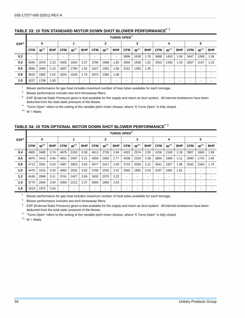
TABLE 33: 10 TON STANDARD MOTOR DOWN SHOT BLOWER PERFORMANCE* †
ESP‡
TURNS OPEN**
0 1 2 3 4 5
CFM W†† BHP CFM W†† BHP CFM W†† BHP CFM W†† BHP CFM W†† BHP CFM W†† BHP
0.2 - - - - - - - - - 3896 1639 1.76 3688 1453 1.56 3447 1268 1.36
0.4 4040 2076 2.23 4005 1934 2.07 3790 1698 1.82 3569 1508 1.62 3333 1330 1.43 3057 1147 1.23
0.6 3890 2006 2.15 3697 1790 1.92 3427 1550 1.66 3152 1356 1.45 - - - - - -
0.8 3620 1882 2.02 3324 1629 1.75 2972 1380 1.48 - - - - - - - - -
1.0 3227 1708 1.83 - - - - - - - - - - - - - - -
*. Blower performance for gas heat includes maximum number of heat tubes available for each tonnage.†. Blower performance includes two-inch throwaway filters.‡. ESP (External Static Pressure) given is that available for the supply and return air duct system. All internal resistances have been
deducted from the total static pressure of the blower.**. “Turns Open” refers to the setting of the variable pitch motor sheave, where “0 Turns Open” is fully closed.††. W = Watts
TABLE 34: 10 TON OPTIONAL MOTOR DOWN SHOT BLOWER PERFORMANCE* †
ESP‡
TURNS OPEN**
0 1 2 3 4 5
CFM W†† BHP CFM W†† BHP CFM W†† BHP CFM W†† BHP CFM W†† BHP CFM W†† BHP
0.4 4965 3485 3.74 4875 3150 3.38 4613 2739 2.94 4322 2374 2.55 4156 2106 2.26 3907 1860 1.99
0.6 4876 3416 3.66 4651 2997 3.21 4359 2582 2.77 4038 2220 2.38 3860 1966 2.11 3590 1724 1.85
0.8 4713 3291 3.53 4387 2823 3.03 4077 2417 2.59 3719 2059 2.21 3541 1827 1.96 3242 1584 1.70
1.0 4476 3116 3.34 4084 2632 2.82 3768 2245 2.41 3365 1892 2.03 3197 1691 1.81 - - -
1.2 4165 2898 3.11 3741 2427 2.60 3432 2070 2.22 - - - - - - - - -
1.4 3779 2646 2.84 3359 2212 2.37 3069 1895 2.03 - - - - - - - - -
1.6 3319 2372 2.54 - - - - - - - - - - - - - - -
*. Blower performance for gas heat includes maximum number of heat tubes available for each tonnage.†. Blower performance includes two-inch throwaway filters.‡. ESP (External Static Pressure) given is that available for the supply and return air duct system. All internal resistances have been
deducted from the total static pressure of the blower.**. “Turns Open” refers to the setting of the variable pitch motor sheave, where “0 Turns Open” is fully closed.††. W = Watts
035-17377-000 REV A (0201)
Unitary Products Group 35
TABLE 35: 12-1/2 TON STANDARD MOTOR DOWN SHOT BLOWER PERFORMANCE* †
ESP‡
TURNS OPEN**
0 1 2 3 4 5
CFM W†† BHP CFM W†† BHP CFM W†† BHP CFM W†† BHP CFM W†† BHP CFM W†† BHP
0.4 5078 3630 3.89 4809 3103 3.33 4594 3053 3.27 4360 2478 2.66 4090 2093 2.24 3812 1798 1.93
0.6 4865 3456 3.71 4584 2961 3.17 4349 2912 3.12 4106 2318 2.49 3814 1964 2.11 - - -
0.8 4642 3284 3.52 4356 2828 3.03 4089 2776 2.98 3840 2137 2.29 - - - - - -
1.0 4408 3114 3.34 4124 2705 2.90 3815 2647 2.84 - - - - - - - - -
1.2 4164 2947 3.16 3889 2592 2.78 - - - - - - - - - - - -
1.4 3910 2787 2.99 - - - - - - - - - - - - - - -
*. Blower performance for gas heat includes maximum number of heat tubes available for each tonnage.†. Blower performance includes two-inch throwaway filters.‡. ESP (External Static Pressure) given is that available for the supply and return air duct system. All internal resistances have been
deducted from the total static pressure of the blower.**. “Turns Open” refers to the setting of the variable pitch motor sheave, where “0 Turns Open” is fully closed.††. W = Watts
TABLE 36: 12-1/2 TON OPTIONAL MOTOR DOWN SHOT BLOWER PERFORMANCE* †
ESP‡
TURNS OPEN**
0 1 2 3 4 5
CFM W†† BHP CFM W†† BHP CFM W†† BHP CFM W†† BHP CFM W†† BHP CFM W†† BHP
0.4 5994 5400 5.79 5565 4369 4.69 5488 4169 4.47 5264 3599 3.86 4990 3085 3.31 4738 2812 3.02
0.6 5824 5216 5.59 5368 4186 4.49 5289 3991 4.28 5049 3437 3.69 4763 2937 3.15 4491 2655 2.85
0.8 5641 5022 5.39 5170 4012 4.30 5076 3807 4.08 4822 3272 3.51 4528 2790 2.99 4235 2497 2.68
1.0 5444 4819 5.17 4971 3846 4.12 4847 3618 3.88 4584 3103 3.33 4286 2644 2.83 3969 2340 2.51
1.2 5233 4609 4.94 4771 3687 3.95 4604 3426 3.67 4335 2933 3.15 4035 2499 2.68 - - -
1.4 5009 4394 4.71 4571 3537 3.79 4346 3233 3.47 4074 2762 2.96 3777 2356 2.53 - - -
1.6 4771 4174 4.48 4370 3395 3.64 4074 3040 3.26 3802 2590 2.78 - - - - - -
1.8 4520 3951 4.24 4169 3262 3.50 3786 2850 3.06 - - - - - - - - -
2.0 4255 3728 4.00 3966 3137 3.36 - - - - - - - - - - - -
2.2 3976 3505 3.76 3763 3020 3.24 - - - - - - - - - - - -
*. Blower performance for gas heat includes maximum number of heat tubes available for each tonnage.†. Blower performance includes two-inch throwaway filters.‡. ESP (External Static Pressure) given is that available for the supply and return air duct system. All internal resistances have been
deducted from the total static pressure of the blower.**. “Turns Open” refers to the setting of the variable pitch motor sheave, where “0 Turns Open” is fully closed.††. W = Watts
035-17377-000 (0201) REV A
36 Unitary Products Group
TABLE 37: 6-1/2 TON STANDARD MOTOR SIDE SHOT BLOWER PERFORMANCE* †
ESP‡
TURNS OPEN**
0 1 2 3 4 5
CFMW†† BHP CFM W†† BHP CFM W†† BHP CFM W†† BHP CFM W†
†BHP CFM W†
†BHP
0.4 - - - - - - 3367 1216 1.30 3133 1067 1.14 2954 944 1.01 2701 819 0.88
0.6 - - - 3208 1239 1.33 2913 1068 1.15 2466 913 0.98 2350 789 0.85 1750 621 0.67
0.8 - - - 2651 1058 1.13 2317 894 0.96 1656 700 0.75 - - - - - -
1.0 2186 998 1.07 1774 830 0.89 - - - - - - - - - - - -
*. Blower performance for gas heat includes maximum number of heat tubes available for each tonnage.†. Blower performance includes two-inch throwaway filters.‡. ESP (External Static Pressure) given is that available for the supply and return air duct system. All internal resistances have been
deducted from the total static pressure of the blower.**. “Turns Open” refers to the setting of the variable pitch motor sheave, where “0 Turns Open” is fully closed.††. W = Watts
TABLE 38: 6-1/2 TON OPTIONAL MOTOR SIDE SHOT BLOWER PERFORMANCE* †
ESP‡
TURNS OPEN**
0 1 2 3 4 5
CFM W†† BHP CFM W†† BHP CFM W†† BHP CFM W†† BHP CFM W†† BHP CFM W†† BHP
0.6 - - - - - - - - - - - - - - - 3597 1598 1.71
0.8 - - - - - - - - - - - - 3503 1689 1.81 3172 1430 1.53
1.0 - - - - - - 3406 1778 1.91 3032 1497 1.61 2248 1143 1.23
1.2 - - - - - - 3327 1866 2.00 2926 1578 1.69 2160 1217 1.31 - - -
1.4 - - - 3270 1971 2.11 2537 1544 1.66 2043 1296 1.39 - - - - - -
1.6 3196 2077 2.23 2460 1651 1.77 1858 1318 1.41 - - - - - - - - -
1.8 2426 1768 1.90 - - - - - - - - - - - - - - -
*. Blower performance for gas heat includes maximum number of heat tubes available for each tonnage.†. Blower performance includes two-inch throwaway filters.‡. ESP (External Static Pressure) given is that available for the supply and return air duct system. All internal resistances have been
deducted from the total static pressure of the blower.**. “Turns Open” refers to the setting of the variable pitch motor sheave, where “0 Turns Open” is fully closed.††. W = Watts
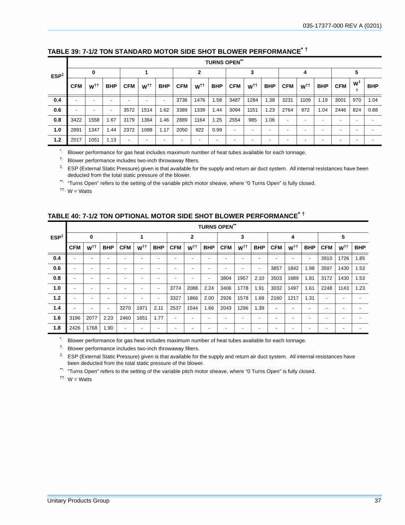
035-17377-000 REV A (0201)
Unitary Products Group 37
TABLE 39: 7-1/2 TON STANDARD MOTOR SIDE SHOT BLOWER PERFORMANCE* †
ESP‡
TURNS OPEN**
0 1 2 3 4 5
CFM W†† BHP CFM W†† BHP CFM W†† BHP CFM W†† BHP CFM W†† BHP CFM W†
†BHP
0.4 - - - - - - 3736 1476 1.58 3487 1284 1.38 3231 1109 1.19 3001 970 1.04
0.6 - - - 3572 1514 1.62 3389 1339 1.44 3094 1151 1.23 2764 972 1.04 2446 824 0.88
0.8 3422 1558 1.67 3179 1364 1.46 2889 1164 1.25 2554 985 1.06 - - - - - -
1.0 2891 1347 1.44 2372 1088 1.17 2050 922 0.99 - - - - - - - - -
1.2 2017 1051 1.13 - - - - - - - - - - - - - - -
*. Blower performance for gas heat includes maximum number of heat tubes available for each tonnage.†. Blower performance includes two-inch throwaway filters.‡. ESP (External Static Pressure) given is that available for the supply and return air duct system. All internal resistances have been
deducted from the total static pressure of the blower.**. “Turns Open” refers to the setting of the variable pitch motor sheave, where “0 Turns Open” is fully closed.††. W = Watts
TABLE 40: 7-1/2 TON OPTIONAL MOTOR SIDE SHOT BLOWER PERFORMANCE* †
ESP‡
TURNS OPEN**
0 1 2 3 4 5
CFM W†† BHP CFM W†† BHP CFM W†† BHP CFM W†† BHP CFM W†† BHP CFM W†† BHP
0.4 - - - - - - - - - - - - - - - 3910 1726 1.85
0.6 - - - - - - - - - - - - 3857 1842 1.98 3597 1430 1.53
0.8 - - - - - - - - - 3804 1957 2.10 3503 1689 1.81 3172 1430 1.53
1.0 - - - - - - 3774 2088 2.24 3406 1778 1.91 3032 1497 1.61 2248 1143 1.23
1.2 - - - - - - 3327 1866 2.00 2926 1578 1.69 2160 1217 1.31 - - -
1.4 - - - 3270 1971 2.11 2537 1544 1.66 2043 1296 1.39 - - - - - -
1.6 3196 2077 2.23 2460 1651 1.77 - - - - - - - - - - - -
1.8 2426 1768 1.90 - - - - - - - - - - - - - - -
*. Blower performance for gas heat includes maximum number of heat tubes available for each tonnage.†. Blower performance includes two-inch throwaway filters.‡. ESP (External Static Pressure) given is that available for the supply and return air duct system. All internal resistances have
been deducted from the total static pressure of the blower.**. “Turns Open” refers to the setting of the variable pitch motor sheave, where “0 Turns Open” is fully closed.††. W = Watts
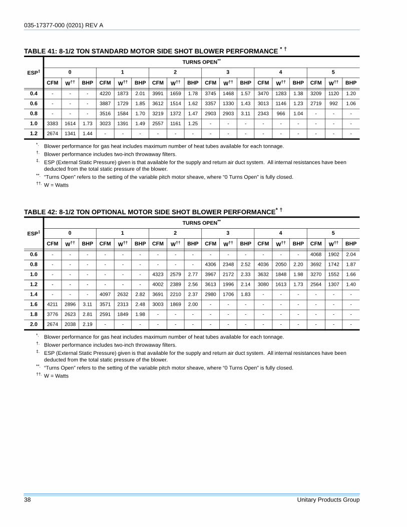
035-17377-000 (0201) REV A
38 Unitary Products Group
TABLE 41: 8-1/2 TON STANDARD MOTOR SIDE SHOT BLOWER PERFORMANCE * †
ESP‡
TURNS OPEN**
0 1 2 3 4 5
CFM W†† BHP CFM W†† BHP CFM W†† BHP CFM W†† BHP CFM W†† BHP CFM W†† BHP
0.4 - - - 4220 1873 2.01 3991 1659 1.78 3745 1468 1.57 3470 1283 1.38 3209 1120 1.20
0.6 - - - 3887 1729 1.85 3612 1514 1.62 3357 1330 1.43 3013 1146 1.23 2719 992 1.06
0.8 - - - 3516 1584 1.70 3219 1372 1.47 2903 2903 3.11 2343 966 1.04 - - -
1.0 3383 1614 1.73 3023 1391 1.49 2557 1161 1.25 - - - - - - - - -
1.2 2674 1341 1.44 - - - - - - - - - - - - - - -
*. Blower performance for gas heat includes maximum number of heat tubes available for each tonnage.†. Blower performance includes two-inch throwaway filters.‡. ESP (External Static Pressure) given is that available for the supply and return air duct system. All internal resistances have been
deducted from the total static pressure of the blower.**. “Turns Open” refers to the setting of the variable pitch motor sheave, where “0 Turns Open” is fully closed.††. W = Watts
TABLE 42: 8-1/2 TON OPTIONAL MOTOR SIDE SHOT BLOWER PERFORMANCE* †
ESP‡
TURNS OPEN**
0 1 2 3 4 5
CFM W†† BHP CFM W†† BHP CFM W†† BHP CFM W†† BHP CFM W†† BHP CFM W†† BHP
0.6 - - - - - - - - - - - - - - - 4068 1902 2.04
0.8 - - - - - - - - - 4306 2348 2.52 4036 2050 2.20 3692 1742 1.87
1.0 - - - - - - 4323 2579 2.77 3967 2172 2.33 3632 1848 1.98 3270 1552 1.66
1.2 - - - - - - 4002 2389 2.56 3613 1996 2.14 3080 1613 1.73 2564 1307 1.40
1.4 - - - 4097 2632 2.82 3691 2210 2.37 2980 1706 1.83 - - - - - -
1.6 4211 2896 3.11 3571 2313 2.48 3003 1869 2.00 - - - - - - - - -
1.8 3776 2623 2.81 2591 1849 1.98 - - - - - - - - - - - -
2.0 2674 2038 2.19 - - - - - - - - - - - - - - -
*. Blower performance for gas heat includes maximum number of heat tubes available for each tonnage.†. Blower performance includes two-inch throwaway filters.‡. ESP (External Static Pressure) given is that available for the supply and return air duct system. All internal resistances have been
deducted from the total static pressure of the blower.**. “Turns Open” refers to the setting of the variable pitch motor sheave, where “0 Turns Open” is fully closed.††. W = Watts
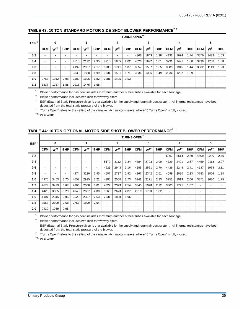
035-17377-000 REV A (0201)
Unitary Products Group 39
TABLE 43: 10 TON STANDARD MOTOR SIDE SHOT BLOWER PERFORMANCE* †
ESP‡
TURNS OPEN**
0 1 2 3 4 5
CFM W†† BHP CFM W†† BHP CFM W†† BHP CFM W†† BHP CFM W†† BHP CFM W†† BHP
0.2 - - - - - - - - - 4368 1843 1.98 4132 1624 1.74 3870 1423 1.53
0.4 - - - 4515 2192 2.35 4213 1885 2.02 4020 1692 1.81 3791 1491 1.60 3499 1283 1.38
0.6 - - - 4192 2027 2.17 3905 1741 1.87 3657 1537 1.65 3383 1345 1.44 3062 1149 1.23
0.8 - - - 3838 1858 1.99 3534 1591 1.71 3236 1386 1.49 2934 1202 1.29 - - -
1.0 3755 1942 2.08 3489 1695 1.82 3081 1425 1.53 - - - - - - - - -
1.2 3337 1757 1.88 2918 1475 1.58 - - - - - - - - - - - -
*. Blower performance for gas heat includes maximum number of heat tubes available for each tonnage.†. Blower performance includes two-inch throwaway filters.‡. ESP (External Static Pressure) given is that available for the supply and return air duct system. All internal resistances have been
deducted from the total static pressure of the blower.**. “Turns Open” refers to the setting of the variable pitch motor sheave, where “0 Turns Open” is fully closed.††. W = Watts
TABLE 44: 10 TON OPTIONAL MOTOR SIDE SHOT BLOWER PERFORMANCE* †
ESP‡
TURNS OPEN**
0 1 2 3 4 5
CFM W†† BHP CFM W†† BHP CFM W†† BHP CFM W†† BHP CFM W†† BHP CFM W†† BHP
0.2 - - - - - - - - - - - - 5067 2614 2.80 4809 2290 2.46
0.4 - - - - - - 5179 3112 3.34 4884 2703 2.90 4729 2401 2.57 4459 2113 2.27
0.6 - - - - - - 4925 2943 3.16 4585 2521 2.70 4429 2244 2.41 4137 1964 2.11
0.8 - - - 4974 3220 3.45 4607 2727 2.92 4267 2342 2.51 4099 2080 2.23 3783 1809 1.94
1.0 4975 3453 3.70 4657 2995 3.21 4305 2550 2.73 3941 2171 2.33 3751 1919 2.06 3371 1630 1.75
1.2 4679 3423 3.67 4366 2808 3.01 4022 2373 2.54 3545 1978 2.12 3305 1741 1.87 - - -
1.4 4429 3065 3.29 4040 2607 2.80 3669 2673 2.87 2918 1700 1.82 - - - - - -
1.6 4107 2845 3.05 3620 2357 2.53 2931 1830 1.96 - - - - - - - - -
1.8 3553 2500 2.68 2756 1899 2.04 - - - - - - - - - - - -
2.0 2439 1939 2.08 - - - - - - - - - - - - - - -
*. Blower performance for gas heat includes maximum number of heat tubes available for each tonnage.†. Blower performance includes two-inch throwaway filters.‡. ESP (External Static Pressure) given is that available for the supply and return air duct system. All internal resistances have been
deducted from the total static pressure of the blower.**. “Turns Open” refers to the setting of the variable pitch motor sheave, where “0 Turns Open” is fully closed.††. W = Watts
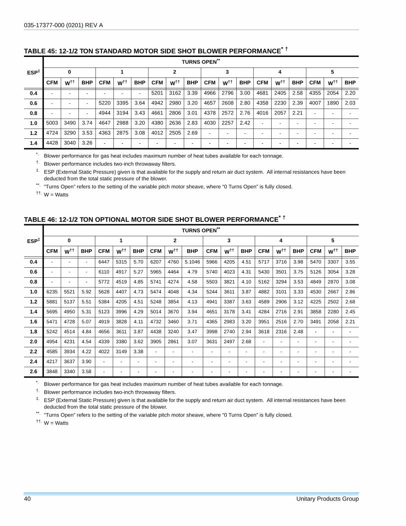
035-17377-000 (0201) REV A
40 Unitary Products Group
TABLE 45: 12-1/2 TON STANDARD MOTOR SIDE SHOT BLOWER PERFORMANCE* †
ESP‡
TURNS OPEN**
0 1 2 3 4 5
CFM W†† BHP CFM W†† BHP CFM W†† BHP CFM W†† BHP CFM W†† BHP CFM W†† BHP
0.4 - - - - - - 5201 3162 3.39 4966 2796 3.00 4681 2405 2.58 4355 2054 2.20
0.6 - - - 5220 3395 3.64 4942 2980 3.20 4657 2608 2.80 4358 2230 2.39 4007 1890 2.03
0.8 - - - 4944 3194 3.43 4661 2806 3.01 4378 2572 2.76 4016 2057 2.21 - - -
1.0 5003 3490 3.74 4647 2988 3.20 4380 2636 2.83 4030 2257 2.42 - - - - - -
1.2 4724 3290 3.53 4363 2875 3.08 4012 2505 2.69 - - - - - - - - -
1.4 4428 3040 3.26 - - - - - - - - - - - - - - -
*. Blower performance for gas heat includes maximum number of heat tubes available for each tonnage.†. Blower performance includes two-inch throwaway filters.‡. ESP (External Static Pressure) given is that available for the supply and return air duct system. All internal resistances have been
deducted from the total static pressure of the blower.**. “Turns Open” refers to the setting of the variable pitch motor sheave, where “0 Turns Open” is fully closed.††. W = Watts
TABLE 46: 12-1/2 TON OPTIONAL MOTOR SIDE SHOT BLOWER PERFORMANCE* †
ESP‡
TURNS OPEN**
0 1 2 3 4 5
CFM W†† BHP CFM W†† BHP CFM W†† BHP CFM W†† BHP CFM W†† BHP CFM W†† BHP
0.4 - - - 6447 5315 5.70 6207 4760 5.1046 5966 4205 4.51 5717 3716 3.98 5470 3307 3.55
0.6 - - - 6110 4917 5.27 5965 4464 4.79 5740 4023 4.31 5430 3501 3.75 5126 3054 3.28
0.8 - - - 5772 4519 4.85 5741 4274 4.58 5503 3821 4.10 5162 3294 3.53 4849 2870 3.08
1.0 6235 5521 5.92 5628 4407 4.73 5474 4048 4.34 5244 3611 3.87 4882 3101 3.33 4530 2667 2.86
1.2 5881 5137 5.51 5384 4205 4.51 5248 3854 4.13 4941 3387 3.63 4589 2906 3.12 4225 2502 2.68
1.4 5695 4950 5.31 5123 3996 4.29 5014 3670 3.94 4651 3178 3.41 4284 2716 2.91 3858 2280 2.45
1.6 5471 4728 5.07 4919 3828 4.11 4732 3460 3.71 4365 2983 3.20 3951 2516 2.70 3491 2058 2.21
1.8 5242 4514 4.84 4656 3611 3.87 4438 3240 3.47 3998 2740 2.94 3618 2316 2.48 - - -
2.0 4954 4231 4.54 4339 3380 3.62 3905 2861 3.07 3631 2497 2.68 - - - - - -
2.2 4585 3934 4.22 4022 3149 3.38 - - - - - - - - - - - -
2.4 4217 3637 3.90 - - - - - - - - - - - - - - -
2.6 3848 3340 3.58 - - - - - - - - - - - - - - -
*. Blower performance for gas heat includes maximum number of heat tubes available for each tonnage.†. Blower performance includes two-inch throwaway filters.‡. ESP (External Static Pressure) given is that available for the supply and return air duct system. All internal resistances have been
deducted from the total static pressure of the blower.**. “Turns Open” refers to the setting of the variable pitch motor sheave, where “0 Turns Open” is fully closed.††. W = Watts
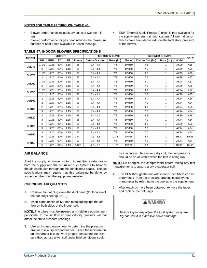
035-17377-000 REV A (0201)
Unitary Products Group 41
NOTES FOR TABLE 27 THROUGH TABLE 46:
• Blower performance includes dry coil and two-inch fil-ters.
• Blower performance for gas heat includes the maximum number of heat tubes available for each tonnage.
• ESP (External Static Pressure) given is that available for the supply and return air duct system. All internal resis-tances have been deducted from the total static pressure of the blower.
AIR BALANCE
Start the supply air blower motor. Adjust the resistances inboth the supply and the return air duct systems to balancethe air distribution throughout the conditioned space. The jobspecifications may require that this balancing be done bysomeone other than the equipment installer.
CHECKING AIR QUANTITY
1. Remove the dot plugs from the duct panel (for location of the dot plugs see figure 10).
2. Insert eight-inches of 1/4 inch metal tubing into the air-flow on both sides of the indoor coil.
NOTE: The tubes must be inserted and held in a position per-pendicular to the air flow so that velocity pressure will notaffect the static pressure readings.
3. Use an inclined manometer to determine the pressure drop across a dry evaporator coil. Since the moisture on an evaporator coil can vary greatly, measuring the pres-sure drop across a wet coil under field conditions could
be inaccurate. To assure a dry coil, the compressors should be de-activated while the test is being run.
NOTE: De-energize the compressors before taking any testmeasurements to assure a dry evaporator coil.
4. The CFM through the unit with clean 2 inch filters can be determined from the pressure drop indicated by the manometer by referring to the curves in the supplement.
5. After readings have been obtained, remove the tubes and replace the dot plugs.
TABLE 47: INDOOR BLOWER SPECIFICATIONS
MODELMOTOR MOTOR SHEAVE BLOWER SHEAVE
BELTHP RPM Eff. SF Frame Datum Dia. (in.) Bore (in.) Model Datum Dia. (in.) Bore (in.) Model
DM0781-1/2 1725 80% 1.15 56 3.4 - 4.4 7/8 1VM50 9.5 1 AK99 A58
2 1725 80% 1.15 56 3.4 - 4.4 7/8 1VM50 7.5 1 AK79 A55
DH0781-1/2 1725 80% 1.15 56 3.4 - 4.4 7/8 1VM50 9.5 1 AK99 A58
2 1725 80% 1.15 56 3.4 - 4.4 7/8 1VM50 7.5 1 AK79 A55
DM0901-1/2 1725 80% 1.15 56 3.4 - 4.4 7/8 1VM50 9.0 1 AK94 A57
2 1725 80% 1.15 56 3.4 - 4.4 7/8 1VM50 7.5 1 AK79 A55
DH0901-1/2 1725 80% 1.15 56 3.4 - 4.4 7/8 1VM50 9.0 1 AK94 A57
2 1725 80% 1.15 56 3.4 - 4.4 7/8 1VM50 7.5 1 AK79 A55
DM1022 1725 80% 1.15 56 3.4 - 4.4 7/8 1VM50 9.0 1 AK94 A56
3 1725 80% 1.15 56 3.4 - 4.4 7/8 1VM50 7.0 1 AK74 A54
DH1022 1725 80% 1.15 56 3.4 - 4.4 7/8 1VM50 9.0 1 AK94 A56
3 1725 80% 1.15 56 3.4 - 4.4 7/8 1VM50 7.0 1 AK74 A54
DM1202 1725 80% 1.15 56 3.4 - 4.4 7/8 1VM50 8.5 1 AK89 A56
3 1725 80% 1.15 56 3.4 - 4.4 7/8 1VM50 7.0 1 AK74 A54
DH1202 1725 80% 1.15 56 3.4 - 4.4 7/8 1VM50 8.5 1 AK89 A56
3 1725 80% 1.15 56 3.4 - 4.4 7/8 1VM50 7.0 1 AK74 A54
DM1503 1725 80% 1.15 56 3.4 - 4.4 7/8 1VM50 7.0 1 AK74 A54
5 1725 87% 1.15 184T 4.3 - 5.3 1 1/8 1VP56 6.7 1 BK77 BX55
DH1503 1725 80% 1.15 56 3.4 - 4.4 7/8 1VM50 7.0 1 AK74 A54
5 1725 87% 1.15 184T 4.3 - 5.3 1 1/8 1VP56 6.7 1 BK77 BX55
Failure to properly adjust the total system air quan-tity can result in extensive blower damage.
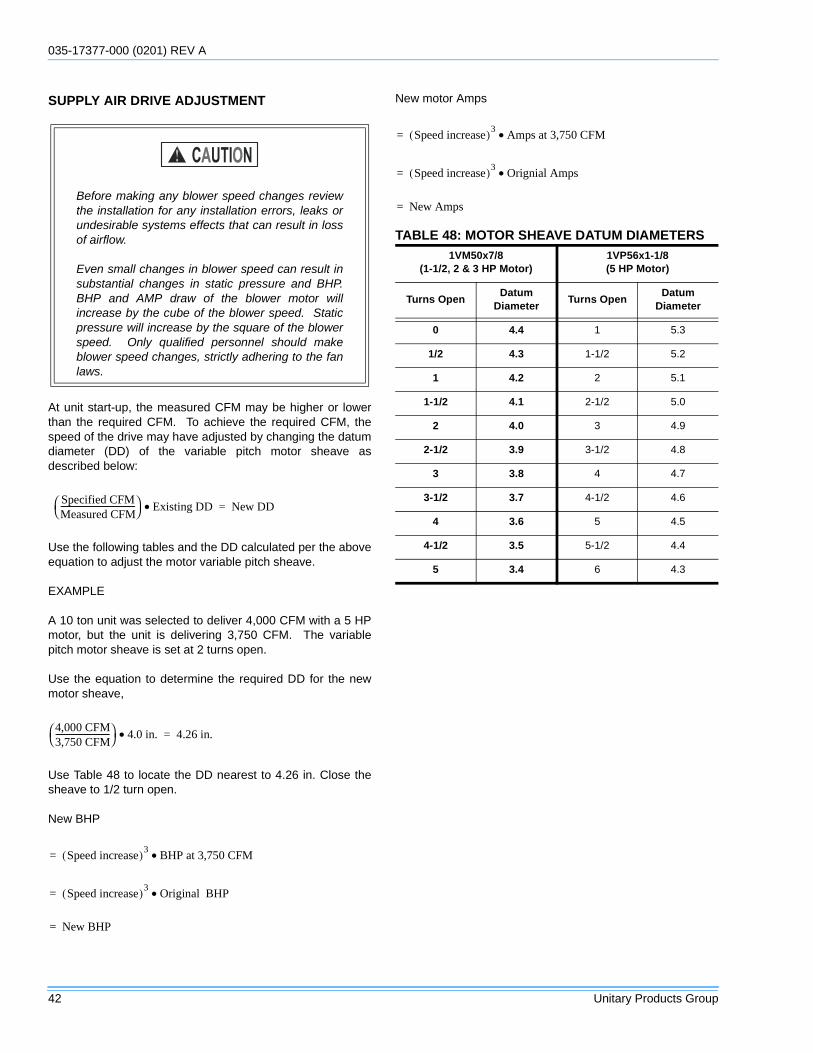
035-17377-000 (0201) REV A
42 Unitary Products Group
SUPPLY AIR DRIVE ADJUSTMENT
At unit start-up, the measured CFM may be higher or lowerthan the required CFM. To achieve the required CFM, thespeed of the drive may have adjusted by changing the datumdiameter (DD) of the variable pitch motor sheave asdescribed below:
Use the following tables and the DD calculated per the aboveequation to adjust the motor variable pitch sheave.
EXAMPLE
A 10 ton unit was selected to deliver 4,000 CFM with a 5 HPmotor, but the unit is delivering 3,750 CFM. The variablepitch motor sheave is set at 2 turns open.
Use the equation to determine the required DD for the newmotor sheave,
Use Table 48 to locate the DD nearest to 4.26 in. Close thesheave to 1/2 turn open.
New BHP
New motor Amps
Before making any blower speed changes reviewthe installation for any installation errors, leaks orundesirable systems effects that can result in lossof airflow.
Even small changes in blower speed can result insubstantial changes in static pressure and BHP.BHP and AMP draw of the blower motor willincrease by the cube of the blower speed. Staticpressure will increase by the square of the blowerspeed. Only qualified personnel should makeblower speed changes, strictly adhering to the fanlaws.
Specified CFMMeasured CFM-------------------------------------
Existing DD• New DD=
4,000 CFM3,750 CFM---------------------------
4.0 in.• 4.26 in.=
Speed increase( )3BHP at 3,750 CFM•=
Speed increase( )3Original BHP•=
New BHP=
TABLE 48: MOTOR SHEAVE DATUM DIAMETERS1VM50x7/8
(1-1/2, 2 & 3 HP Motor)1VP56x1-1/8(5 HP Motor)
Turns OpenDatum
DiameterTurns Open
Datum Diameter
0 4.4 1 5.3
1/2 4.3 1-1/2 5.2
1 4.2 2 5.1
1-1/2 4.1 2-1/2 5.0
2 4.0 3 4.9
2-1/2 3.9 3-1/2 4.8
3 3.8 4 4.7
3-1/2 3.7 4-1/2 4.6
4 3.6 5 4.5
4-1/2 3.5 5-1/2 4.4
5 3.4 6 4.3
Speed increase( )3= Amps at 3,750 CFM•
Speed increase( )=3
Orignial Amps•
New Amps=
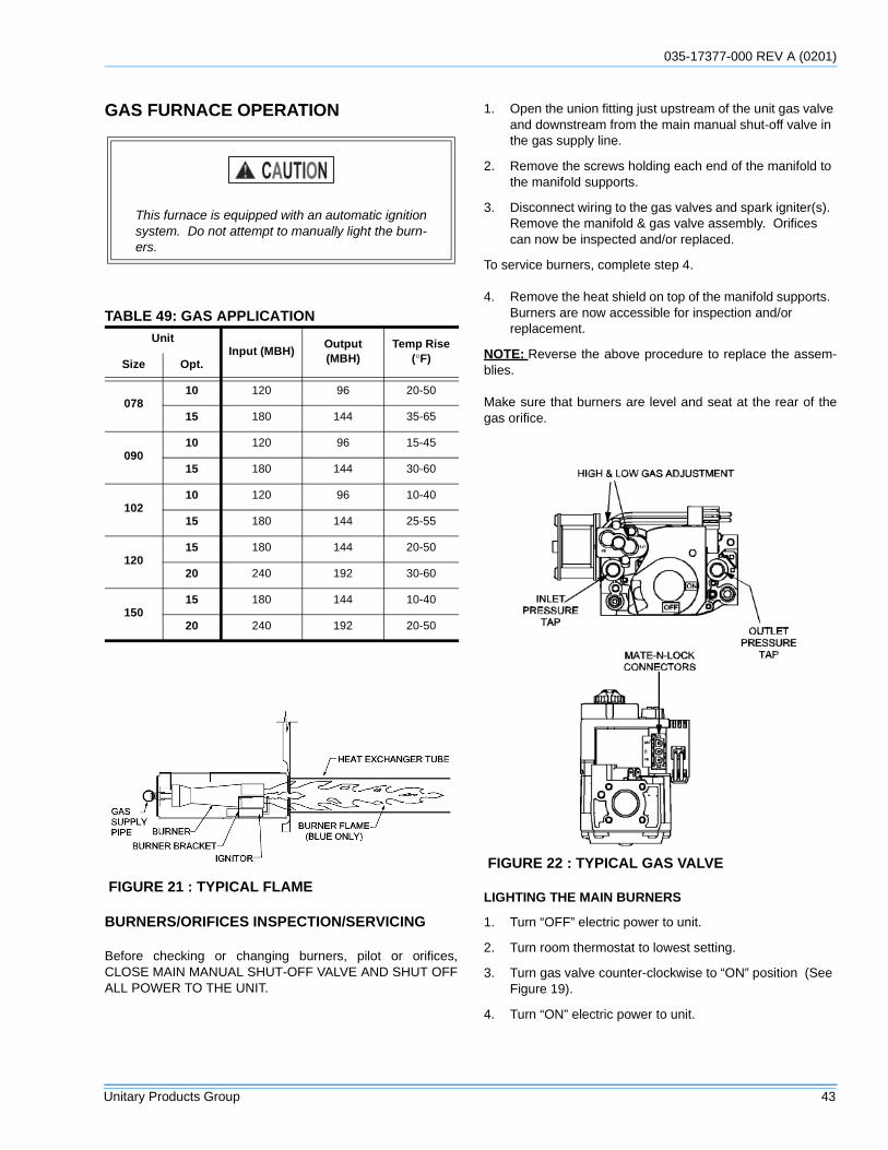
035-17377-000 REV A (0201)
Unitary Products Group 43
GAS FURNACE OPERATION
BURNERS/ORIFICES INSPECTION/SERVICING
Before checking or changing burners, pilot or orifices,CLOSE MAIN MANUAL SHUT-OFF VALVE AND SHUT OFFALL POWER TO THE UNIT.
1. Open the union fitting just upstream of the unit gas valve and downstream from the main manual shut-off valve in the gas supply line.
2. Remove the screws holding each end of the manifold to the manifold supports.
3. Disconnect wiring to the gas valves and spark igniter(s). Remove the manifold & gas valve assembly. Orifices can now be inspected and/or replaced.
To service burners, complete step 4.
4. Remove the heat shield on top of the manifold supports. Burners are now accessible for inspection and/or replacement.
NOTE: Reverse the above procedure to replace the assem-blies.
Make sure that burners are level and seat at the rear of thegas orifice.
LIGHTING THE MAIN BURNERS
1. Turn “OFF” electric power to unit.
2. Turn room thermostat to lowest setting.
3. Turn gas valve counter-clockwise to “ON” position (See Figure 19).
4. Turn “ON” electric power to unit.
This furnace is equipped with an automatic ignitionsystem. Do not attempt to manually light the burn-ers.
TABLE 49: GAS APPLICATIONUnit
Input (MBH)Output (MBH)
Temp Rise (°F)Size Opt.
07810 120 96 20-50
15 180 144 35-65
09010 120 96 15-45
15 180 144 30-60
10210 120 96 10-40
15 180 144 25-55
12015 180 144 20-50
20 240 192 30-60
15015 180 144 10-40
20 240 192 20-50
FIGURE 21 : TYPICAL FLAME
FIGURE 22 : TYPICAL GAS VALVE
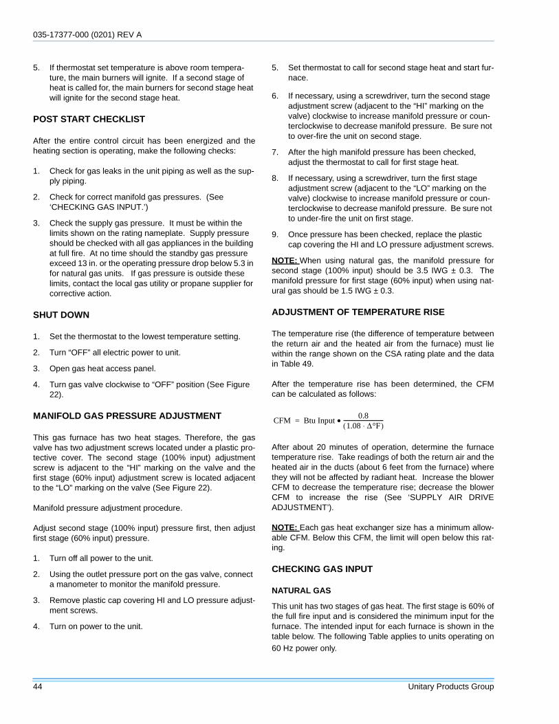
035-17377-000 (0201) REV A
44 Unitary Products Group
5. If thermostat set temperature is above room tempera-ture, the main burners will ignite. If a second stage of heat is called for, the main burners for second stage heat will ignite for the second stage heat.
POST START CHECKLIST
After the entire control circuit has been energized and theheating section is operating, make the following checks:
1. Check for gas leaks in the unit piping as well as the sup-ply piping.
2. Check for correct manifold gas pressures. (See ‘CHECKING GAS INPUT.’)
3. Check the supply gas pressure. It must be within the limits shown on the rating nameplate. Supply pressure should be checked with all gas appliances in the building at full fire. At no time should the standby gas pressure exceed 13 in. or the operating pressure drop below 5.3 in for natural gas units. If gas pressure is outside these limits, contact the local gas utility or propane supplier for corrective action.
SHUT DOWN
1. Set the thermostat to the lowest temperature setting.
2. Turn “OFF” all electric power to unit.
3. Open gas heat access panel.
4. Turn gas valve clockwise to “OFF” position (See Figure 22).
MANIFOLD GAS PRESSURE ADJUSTMENT
This gas furnace has two heat stages. Therefore, the gasvalve has two adjustment screws located under a plastic pro-tective cover. The second stage (100% input) adjustmentscrew is adjacent to the “HI” marking on the valve and thefirst stage (60% input) adjustment screw is located adjacentto the “LO” marking on the valve (See Figure 22).
Manifold pressure adjustment procedure.
Adjust second stage (100% input) pressure first, then adjustfirst stage (60% input) pressure.
1. Turn off all power to the unit.
2. Using the outlet pressure port on the gas valve, connect a manometer to monitor the manifold pressure.
3. Remove plastic cap covering HI and LO pressure adjust-ment screws.
4. Turn on power to the unit.
5. Set thermostat to call for second stage heat and start fur-nace.
6. If necessary, using a screwdriver, turn the second stage adjustment screw (adjacent to the “HI” marking on the valve) clockwise to increase manifold pressure or coun-terclockwise to decrease manifold pressure. Be sure not to over-fire the unit on second stage.
7. After the high manifold pressure has been checked, adjust the thermostat to call for first stage heat.
8. If necessary, using a screwdriver, turn the first stage adjustment screw (adjacent to the “LO” marking on the valve) clockwise to increase manifold pressure or coun-terclockwise to decrease manifold pressure. Be sure not to under-fire the unit on first stage.
9. Once pressure has been checked, replace the plastic cap covering the HI and LO pressure adjustment screws.
NOTE: When using natural gas, the manifold pressure forsecond stage (100% input) should be 3.5 IWG ± 0.3. Themanifold pressure for first stage (60% input) when using nat-ural gas should be 1.5 IWG ± 0.3.
ADJUSTMENT OF TEMPERATURE RISE
The temperature rise (the difference of temperature betweenthe return air and the heated air from the furnace) must liewithin the range shown on the CSA rating plate and the datain Table 49.
After the temperature rise has been determined, the CFMcan be calculated as follows:
After about 20 minutes of operation, determine the furnacetemperature rise. Take readings of both the return air and theheated air in the ducts (about 6 feet from the furnace) wherethey will not be affected by radiant heat. Increase the blowerCFM to decrease the temperature rise; decrease the blowerCFM to increase the rise (See ‘SUPPLY AIR DRIVEADJUSTMENT’).
NOTE: Each gas heat exchanger size has a minimum allow-able CFM. Below this CFM, the limit will open below this rat-ing.
CHECKING GAS INPUT
NATURAL GAS
This unit has two stages of gas heat. The first stage is 60% ofthe full fire input and is considered the minimum input for thefurnace. The intended input for each furnace is shown in thetable below. The following Table applies to units operating on60 Hz power only.
CFM Btu Input0.8
1.08 ∆°F⋅( )-----------------------------•=
035-17377-000 REV A (0201)
Unitary Products Group 45
1. To determine the rate of gas flow (second Stage).
2. Turn of all other gas appliances connected to the gas meter.
3. Turn on the furnace and make sure the thermostat is calling for Second stage (100% input) heat.
4. Measure the time needed for one revolution of the hand on the smallest dial on the meter. A typical gas meter has a 1/2 or a 1 cubic foot test dial.
5. Using the number of seconds it takes for one revolution of the dial, calculate the cubic feet of gas consumed per hour. (See example below).
6. If necessary, adjust the high pressure regulator as dis-cussed in the section “Manifold Gas Pressure Adjust-ment”. Be sure not to over-fire the furnace on Second stage. If in doubt, it is better to leave the Second stage of the furnace slightly under-fired. Repeat Steps 1-5.
To determine the rate of gas flow (First Stage)
1. Turn of all other gas appliances connected to the gas meter.
2. Turn on the furnace and make sure the thermostat is calling for first stage (60% input) heat.
3. Even when the thermostat is calling for first stage heat, the unit will light on second stage and will run on Second stage for 1 minute. Allow this one-minute time period to expire and be certain the unit is running on first stage.
4. Measure the time needed for one revolution of the hand on the smallest dial on the meter. A typical gas meter has a 1/2 or a 1 cubic foot test dial.
5. Using the number of seconds it takes for one revolution of the dial, calculate the cubic feet of gas consumed per hour (See example below).
6. If necessary, adjust the low pressure regulator as dis-cussed in the section “Manifold Gas Pressure Adjust-ment”. Be sure not to under-fire the furnace on first stage. If in doubt, it is better to leave the first stage of the furnace slightly over-fired (greater than 60% input). Repeat Steps 1-6.
NOTE: To find the Btu input, multiply the number of cubic feetof gas consumed per hour by the Btu content of the gas inyour particular locality (contact your gas company for thisinformation as it varies widely from area to area).
EXAMPLE
By actual measurement, it takes 19 seconds for the hand ona 1 cubic foot dial to make a revolution with a 192,000 Btuhfurnace running. To determine rotations per minute, divide 60by 19 = 3.16. To calculate rotations per hour, multiply 3.16 •60 = 189.6. Multiply 189.6 • 1 (0.5 if using a 1/2 cubic footdial) = 189.6. Multiply 189.6 • (the Btu rating of the gas). Forthis example, assume the gas has a Btu rating of 1050Btu/ft.3. The result of 199,000 Btuh is within 5% of the192,000 Btuh rating of the furnace.
TABLE 50: GAS HEAT STAGES
# of Burner Tubes2nd Stage
Input (100%Btuh)
1st StageInput (60%)
Btuh
4 120,000 72,000
6 180,000 108,000
8 240,000 144,000
TABLE 51: GAS RATE CUBIC FEET PER HOURSecondsfor One
Rev.
Size of Test Dial
1/2 cu. ft. 1 cu. ft.
10 180 360
12 150 300
14 129 257
16 113 225
18 100 200
20 90 180
22 82 164
24 75 150
26 69 138
28 64 129
30 60 120
32 56 113
34 53 106
36 50 100
38 47 95
40 45 90
42 43 86
44 41 82
46 39 78
48 37 75
50 36 72
52 35 69
54 34 67
56 32 64
58 31 62
60 30 60
035-17377-000 (0201) REV A
46 Unitary Products Group
COOLING OPERATION INSTRUCTIONS
COOLING SYSTEM PRELIMINARY OPERATION
NOTE: Prior to each cooling season, the crankcase heatersmust be energized at least 10 hours before the system is putinto operation.
TURN ON THE POWER TO THE UNIT
1. Set the room thermostat setting to lower than the room temperature.
2. First stage compressors will energize after the built-in time delay (five minutes).
3. The second stage of the thermostat will energize second stage compressor if needed.
POST START CHECK LIST
VERIFY PROPER SYSTEM PRESSURES FOR BOTH CIR-CUITS
1. Check the unit air flower (CFM). See “CHECKING AIR QUANTITY” on page 41.
2. Measure the temperature drop across the evaporator coil.
3. Check the voltage input.
4. Measure the system Amperage draw across all legs of 3 phase power wires.
5. Measure the condenser fan amps draw.
6. Measure evaporator fan motor’s amp draw.
SHUT DOWN
1. Set the thermostat to highest temperature setting.
2. Turn off the electrical power to the unit.
SEQUENCE OF OPERATIONS
OVERVIEW
For the Predator series of units, the thermostat makes a cir-cuit between “R” and “Y1” for the first stage of cooling.
The call is passed to the unit control board (UCB), which thendetermines whether the requested operation is available and,if so, which components to energize.
For gas heating, the UCB monitors the “W1” call but does nothandle the operation of the gas furnace. An ignition controlboard controls the gas heater operation. For electric heatunits, the UCB passes the call to the electric heater. In bothcases, when the “W1” call is sensed, the indoor air blower isenergized following a specified heating delay.
If at any time a call for both heating and cooling are present,the heating operation will be performed. If operating, thecooling system is halted as with a completion of a call forcooling. Heating always takes priority.
SAFETY CONTROLS
ThePredator unit control board monitors the followinginputs for each cooling system:
1. A suction line freezestat to protect against low evapora-tor temperatures due to a low airflow or a low return air temperature, (opens at 26 ± 5 °F and resets at 38 ± 5 °F).
2. A high-pressure switch to protect against excessive dis-charge pressures due to a blocked condenser coil or a condenser motor failure, (opens at 405 ± 10 psig and resets at 300 ± 10 psig).
3. A low-pressure switch to protect against loss of refriger-ant charge, (opens at 7 ± 3 psig and resets at 22 ± 5 psig).
The above pressure switches are hard-soldered to the unit.The refrigeration systems are independently monitored andcontrolled. On any fault, only the associated system will beeffected by any safety/preventive action. The other refriger-ant system will continue in operation unless it is effected bythe fault as well.
The unit control board monitors the temperature limit switchof electric heat units and the temperature limit switch and thegas valve of gas furnace units.
The ignition control board monitors the temperature limitswitch, the rollout switch, the draft motor proving switch, theflame sensor, and the gas valve.
After installation has been completed, energize thecrankcase heaters for at least four hours beforeoperating unit. After this initial warm-up, the com-pressors should be given three false starts (ener-gized just long enough to make a few revolutions)with 5-7 minutes of delay between each startbefore being put into full time service.
035-17377-000 REV A (0201)
Unitary Products Group 47
PROTECTION
The compressors also have inherent (internal) protection. Ifthere is an abnormal temperature rise in a compressor, theprotector will open to shut down the compressor.
The UCB incorporates features to minimize compressor wearand damage. An anti-short cycle delay (ASCD) is utilized toprevent operation of a compressor too soon after its previousrun. Additionally, a minimum run time is imposed any time acompressor is energized.
The ASCD is initiated on unit start-up and on any compressorreset or lock-out.
CONTINUOUS BLOWER
By setting the room thermostat to “ON,” the supply air blowerwill operate continuously.
INTERMITTENT BLOWER
With the room thermostat fan switch set to “AUTO” and thesystem switch set to either the “AUTO” or “HEAT” settings,the blower is energized whenever a cooling or heating opera-tion is requested. The blower is energized after any specifieddelay associated with the operation.
When energized, the indoor blower has a minimum run timeof 30 seconds. Additionally, the indoor blower has a delay of10 seconds between operations.
COOLING SEQUENCE OF OPERATION
When the thermostat calls for the first stage of cooling, thelow-voltage control circuit from “R” to “Y1” and “G” is com-pleted. The UCB energizes the economizer (if installed andfree cooling is available) or the first available compressor*
and the condenser fans. For first stage cooling, compressor#1 is energized. If compressor #1 is unavailable, compressor#2 is energized. After completing the specified fan on delayfor cooling, the UCB will energize the blower motor.
When the thermostat calls for the second stage of cooling,the low-voltage control circuit from “R” to “Y2” is completed.The control board energizes the first available compressor. Iffree cooling is being used for the first stage of cooling, com-pressor #1 is energized. If compressor #1 is active for firststage cooling or the first compressor is locked-out, compres-sor #2 is energized. In free-cooling mode, if the call for thesecond stage of cooling continues for 20 minutes, compres-sor #2 is energized, provided it has not been locked-out.
If there is an initial call for both stages of cooling, the UCB willdelay energizing compressor #2 by 30 seconds in order toavoid a power rush.
Once the thermostat has been satisfied, the it will de-ener-gize Y1 and Y2. If the compressors have satisfied their mini-mum run times, the compressors and condenser fans are de-energized. Otherwise, the unit operates each cooling systemuntil the minimum run times for the compressors have beencompleted. Upon the final compressor de-energizing, theblower is stopped following the elapse of the fan off delay forcooling.
* To be available, a compressor must not be locked-out dueto a high or low-pressure switch or freezestat trip and theanti-short cycle delay (ASCD) must have elapsed.
COOLING OPERATION ERRORS
Each cooling system is monitored for operation outside of theintended parameters. Errors are handled as describedbelow. All system errors override minimum run times forcompressors.
HIGH-PRESSURE LIMIT SWITCH
During cooling operation, if a high-pressure limit switchopens, the UCB will de-energize the associated compressor,initiate the ASCD, and, if the other compressor is idle, stopthe condenser fans. If the call for cooling is still present at theconclusion of the ASCD, the UCB will re-energize the haltedcompressor.
Should a high-pressure switch open three times within twohours of operation, the UCB will lock-out the associated com-pressor and flash a code (see Table 60). If the other com-pressor is inactive, the condenser fans will be de-energized.
LOW-PRESSURE LIMIT SWITCH
The low-pressure limit switch is not monitored during the ini-tial 30 seconds of a cooling system’s operation. For the fol-lowing 30 seconds, the UCB will monitor the low-pressureswitch to ensure it closes. If the low-pressure switch fails toclose after the 30-second monitoring phase, the UCB will de-energize the associated compressor, initiate the ASCD, and,if the other compressor is idle, stop the condenser fans.
Once the low-pressure switch has been proven (closed dur-ing the 30-second monitor period described above), the UCBwill monitor the low-pressure limit switch for any openings. Ifthe low-pressure switch opens for greater than 5 seconds,the UCB will de-energize the associated compressor, initiatethe ASCD, and, if the other compressor is idle, stop the con-denser fans.
If the call for cooling is still present at the conclusion of theASCD, the UCB will re-energize the halted compressor.
Should a low-pressure switch open three times within onehour of operation, the UCB will lock-out the associated com-pressor and flash a code (Table 60). If the other compressoris inactive, the condenser fans will be de-energized.
035-17377-000 (0201) REV A
48 Unitary Products Group
FREEZESTAT
During cooling operation, if a freezestat opens, the UCB willde-energize the associated compressor, initiate the ASCD,and, if the other compressor is idle, stop the condenser fans.If the call for cooling is still present at the conclusion of theASCD, the UCB will re-energize the halted compressor.
Should a freezestat open three times within two hours ofoperation, the UCB will lock-out the associated compressorand flash a code (Table 60). If the other compressor is inac-tive, the condenser fans will be de-energized.
FLASH CODES
When the UCB has locked-out a compressor, the UCB willinitiate a flash code associated with the error. Also, if thethermostat is so equipped, the UCB will energize the thermo-stat trouble light.
RESET
Remove the call for cooling, by raising thermostat settinghigher than the space temperature. This resets any pressureor freezestat flash codes.
GAS HEATING SEQUENCE OF OPERATIONS
When the thermostat calls for the first stage of heating, thelow-voltage control circuit from “R” to “W1” is completed. Acall for heat passes through the UCB to the ignition controlboard (ICB). The UCB monitors the “W1” call and acts uponany call for heat by monitoring the gas valve (GV). Once volt-age has been sensed at the GV, the UCB will initiate the fanon delay for heating, energizing the indoor blower the speci-fied delay has elapsed.
When the thermostat has been satisfied, heating calls areceased. The GV is immediately closed. The blower is de-energized after the fan off delay for heating has elapsed. Thedraft motor performs a 30-second post purge.
IGNITION CONTROL BOARD
FIRST STAGE OF HEATING
When the ICB receives a call for first stage of heating, “W1,”the draft motor is energized. Once the draft motor has beenproven, a 30-second purge is initiated. At the end of thepurge, both main valves of the GV are opened, and the sparkignitor is energized for 10 seconds. The ICB then checks forthe presence of flame. If flame is detected, the ICB enters aflame stabilization period. If flame was not detected, bothmain valves close, and a retry operation begins.
During the flame stabilization period, a loss of the flame for 2seconds will cause the main valves to close and the retryoperation to begin. After the flame stabilization period, a lossof flame for 3/4 second will cause the main valves to closeand the retry operation to begin.
At the conclusion of the flame stabilization period, the ICB willoperate the gas heat in high fire (both valves open) for anadditional 100 seconds (for a total for 120 seconds of highfire operation). After this 100 seconds, the ICB will then usethe call for the second stage of heat to control the secondmain valve of the GV.
When “W1” is satisfied, both valves are closed.
SECOND STAGE OF HEATING
When the ICB receives a call for the second stage of heating,“W2,” the ICB conducts a complete first stage ignitionsequence. If this sequence is satisfied, the second mainvalve of the GV is opened.
When “W2” is satisfied, the second main valve is closed.
RETRY OPERATION
When a flame is lost or is not detected during an attempt toachieve ignition, a retry operation occurs. A 30-second purgeis performed between ignition attempts.
If the unit fails after three ignition attempts, the furnace islocked-out for one hour. The furnace is monitored during thisone-hour period for unsafe conditions.
RECYCLE OPERATION
When a flame is lost after the flame stabilization period, arecycle operation occurs. If the unit fails after five recycleattempts, the furnace is locked-out for one hour.
GAS HEATING OPERATION FAULTS
LOCK-OUT
A one-hour lockout occurs following three retries or five recy-cles. During the one-hour lockout, flame detection, limit con-ditions, and main valves are tested. Any improper results willcause the appropriate action to occur. Recycling the low volt-age power cancels the lock-out.
TEMPERATURE LIMIT
If the UCB senses zero volts from the high temperature limit,the indoor blower motor is immediately energized. When theUCB again senses 24 volts from the temperature limit, thedraft motor will perform a 15-second post-purge and theindoor blower will be de-energized following the elapse of thefan off delay for heating.
This limit is monitored regardless of unit operation status, i.e.this limit is monitored at all time.
If the temperature limit opens three times within one hour, itwill lock-on the indoor blower motor and flash code is initiated(See Table 60).
035-17377-000 REV A (0201)
Unitary Products Group 49
FLAME SENSE
Flame sensing occurs at all times. If “W1” is not present anda flame is sensed for 2 seconds, the draft motor is energizedand the main valve is kept off. The ICB halts any operationuntil a flame is not detected. Once the flame detection is lost,the ICB performs a post-purge. Normal operation is allowedconcurrently with the purge (i.e. this purge can be consideredthe purge associated with a call for “W1”).
If “W1” is present, a flame is sensed, but the main valve is notenergized, the draft motor is energized until the flame detec-tion is lost. Normal operation is now allowed.
The flame detection circuitry continually tests itself. If the ICBfinds the flame detection circuitry to be faulty, the ICB will notpermit an ignition sequence. Also, the draft motor is ener-gized. If this failure should occur during an ignition cycle thefailure is counted as a recycle.
GAS VALVE
The UCB and ICB continuously monitor the GV.
If the ICB senses voltage at the GV when not requested, theICB will energize the draft motor. The ICB will not operate thefurnace until voltage is no longer sensed at the GV. The draftmotor is stopped when voltage is not sensed at the GV.
Any time the UCB senses voltage at the GV without a call forheat for a continuous five-minute period, the UCB will lock-onthe indoor blower and a flash code is initiated (Table 60).When voltage is no longer sensed at the GV, the UCB will de-energize the indoor blower following the elapse of the fan offdelay for heating.
If voltage has been sensed at the GV for at least 15 secondsduring the fan on delay for heating and GV voltage or “W1” islost, the indoor blower is forced on for the length of the fan offdelay for heating.
During a call for heat, if the UCB does not sense voltage atthe GV for a continuous five-minute period the UCB will ini-tiate a flash code (Table 60). The indoor blower motor will notbe locked-on while there is no GV voltage.
However, if during a normal ignition sequence, the NPC hasbeen tested to be open, IDM energized, NPC closes and thenthe first stage main valve (MV1) is detected as being on, theignition sequence stops and the IDM is de-energized. (Sincethe NPC is wired serially with the main valve relays, de-ener-gizing the IDM will open the NPC). This failure is counted asa recycle and will result in an eventual recycle lockout. If themain valve continues to be energized after the IDM is de-energized the IDM is re-energized. The second stage (MV2)main valve is not monitored for closure after energization.
PRESSURE SWITCH
Once the draft motor has been proven during a normal igni-tion sequence, if proving is lost for 2 seconds, the GV will bede-energized, the ignition cycle is aborted, and the ICBflashes the appropriate code. The draft motor is energizeduntil again proven or “W1” is lost.
ROLLOUT SWITCH
The rollout switch is wired in series with the draft motor prov-ing switch. As such, the ICB cannot distinguish the rolloutswitch operation from that of the draft motor proving switch.Consequently, the control will only respond as in the samemanner as outlined above (under Pressure Switch). Anopen rollout will inhibit the gas valve from actuating.
INTERNAL MICROPROCESSOR FAILURE
If the ICB detects an internal failure, it will turn cease all out-puts, ignore inputs, and display the proper flash code for con-trol replacement. The ICB remains in this condition untilreplaced.
LOW AMBIENT COOLING
To determine when to operate in low ambient mode, the UCBhas a pair of terminals connected to a temperature-activatedswitch. When the low ambient switch is closed and the ther-mostat is calling for cooling, the UCB will operate in the lowambient mode.
Low ambient mode operates the compressors in this manner:10 minutes on, 5 minutes off. The indoor blower is operatedthroughout the cycle. The 5-minute off period is necessary todefrost the indoor coil.
Low ambient mode always begins with compressor opera-tion. Compressor minimum run time may extend the minutesof compressor operation. The defrost cycle will begin immedi-ately following the elapse of the minimum run time.
When operating in low ambient mode, the UCB will not lock-out the compressors due to a freezestat trip. However, afreezestat trip will de-energize the associated compressor. Ifthe call for cooling is still present at the end of the ASCD andthe freezestat has closed, the unit will resume operation.
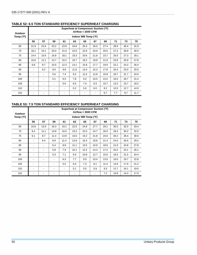
035-17377-000 (0201) REV A
50 Unitary Products Group
TABLE 52: 6.5 TON STANDARD EFFICIENCY SUPERHEAT CHARGING
OutdoorTemp (°F)
Superheat at Compressor Suction (°F)Airflow = 2500 CFM
Indoor WB Temp (°F)
55 57 59 61 63 65 67 69 71 73 75
65 21.9 22.6 23.2 23.9 24.6 25.3 26.0 27.4 28.9 30.4 31.9
70 18.1 19.1 20.0 21.0 22.0 22.9 23.9 25.5 27.2 28.9 30.5
75 14.4 15.6 16.8 18.1 19.3 20.6 21.8 23.7 25.5 27.3 29.1
80 10.6 12.1 13.7 15.2 16.7 18.2 19.8 21.8 23.8 25.8 27.8
85 6.8 8.7 10.5 12.3 14.1 15.9 17.7 19.9 22.1 24.2 26.4
90 - 6.2 8.0 9.8 11.6 13.4 15.3 17.8 20.4 23.0 25.5
95 - - 5.6 7.4 9.2 11.0 12.8 15.8 18.7 21.7 24.6
100 - - 5.1 6.5 7.8 9.2 10.5 13.2 16.0 18.7 21.4
105 - - - 5.6 6.5 7.4 8.3 10.7 13.2 15.7 18.2
110 - - - - 5.2 5.6 6.0 8.2 10.5 12.7 14.9
115 - - - - - - - 5.7 7.7 9.7 11.7
TABLE 53: 7.5 TON STANDARD EFFICIENCY SUPERHEAT CHARGING
OutdoorTemp (°F)
Superheat at Compressor Suction (°F)Airflow = 3000 CFM
Indoor WB Temp (°F)
55 57 59 61 63 65 67 69 71 73 75
65 10.6 13.5 16.3 19.1 22.0 24.8 27.7 29.1 30.5 32.0 33.4
70 8.4 11.1 13.8 16.5 19.3 22.0 24.7 26.5 28.4 30.2 32.0
75 6.1 8.7 11.3 13.9 16.6 19.2 21.8 24.0 26.2 28.4 30.6
80 - 6.4 8.9 11.4 13.9 16.3 18.8 21.4 24.0 26.6 29.2
85 - - 6.4 8.8 11.1 13.5 15.9 18.9 21.9 24.8 27.8
90 - - 5.8 7.9 10.1 12.2 14.3 17.2 20.2 23.1 26.1
95 - - 5.3 7.1 9.0 10.8 12.7 15.6 18.5 21.5 24.4
100 - - - 6.3 7.7 9.0 10.4 13.5 16.6 19.7 22.8
105 - - - 5.5 6.4 7.3 8.1 11.4 14.6 17.9 21.2
110 - - - - 5.1 5.5 5.9 9.3 12.7 16.1 19.5
115 - - - - - - - 7.2 10.8 14.3 17.9
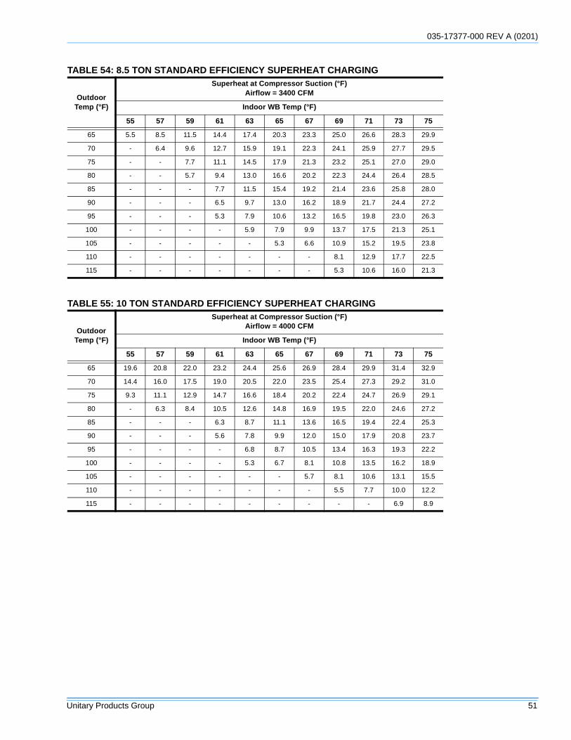
035-17377-000 REV A (0201)
Unitary Products Group 51
TABLE 54: 8.5 TON STANDARD EFFICIENCY SUPERHEAT CHARGING
OutdoorTemp (°F)
Superheat at Compressor Suction (°F)Airflow = 3400 CFM
Indoor WB Temp (°F)
55 57 59 61 63 65 67 69 71 73 75
65 5.5 8.5 11.5 14.4 17.4 20.3 23.3 25.0 26.6 28.3 29.9
70 - 6.4 9.6 12.7 15.9 19.1 22.3 24.1 25.9 27.7 29.5
75 - - 7.7 11.1 14.5 17.9 21.3 23.2 25.1 27.0 29.0
80 - - 5.7 9.4 13.0 16.6 20.2 22.3 24.4 26.4 28.5
85 - - - 7.7 11.5 15.4 19.2 21.4 23.6 25.8 28.0
90 - - - 6.5 9.7 13.0 16.2 18.9 21.7 24.4 27.2
95 - - - 5.3 7.9 10.6 13.2 16.5 19.8 23.0 26.3
100 - - - - 5.9 7.9 9.9 13.7 17.5 21.3 25.1
105 - - - - - 5.3 6.6 10.9 15.2 19.5 23.8
110 - - - - - - - 8.1 12.9 17.7 22.5
115 - - - - - - - 5.3 10.6 16.0 21.3
TABLE 55: 10 TON STANDARD EFFICIENCY SUPERHEAT CHARGING
OutdoorTemp (°F)
Superheat at Compressor Suction (°F)Airflow = 4000 CFM
Indoor WB Temp (°F)
55 57 59 61 63 65 67 69 71 73 75
65 19.6 20.8 22.0 23.2 24.4 25.6 26.9 28.4 29.9 31.4 32.9
70 14.4 16.0 17.5 19.0 20.5 22.0 23.5 25.4 27.3 29.2 31.0
75 9.3 11.1 12.9 14.7 16.6 18.4 20.2 22.4 24.7 26.9 29.1
80 - 6.3 8.4 10.5 12.6 14.8 16.9 19.5 22.0 24.6 27.2
85 - - - 6.3 8.7 11.1 13.6 16.5 19.4 22.4 25.3
90 - - - 5.6 7.8 9.9 12.0 15.0 17.9 20.8 23.7
95 - - - - 6.8 8.7 10.5 13.4 16.3 19.3 22.2
100 - - - - 5.3 6.7 8.1 10.8 13.5 16.2 18.9
105 - - - - - - 5.7 8.1 10.6 13.1 15.5
110 - - - - - - - 5.5 7.7 10.0 12.2
115 - - - - - - - - - 6.9 8.9
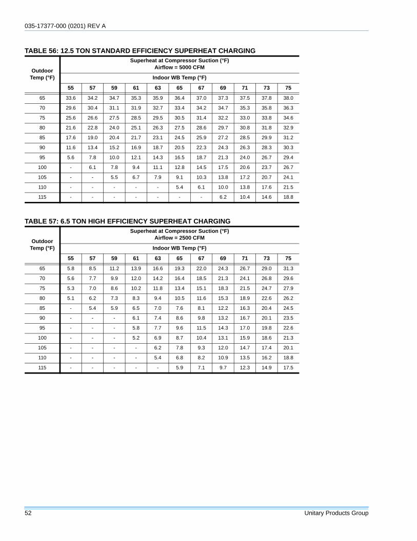
035-17377-000 (0201) REV A
52 Unitary Products Group
TABLE 56: 12.5 TON STANDARD EFFICIENCY SUPERHEAT CHARGING
OutdoorTemp (°F)
Superheat at Compressor Suction (°F)Airflow = 5000 CFM
Indoor WB Temp (°F)
55 57 59 61 63 65 67 69 71 73 75
65 33.6 34.2 34.7 35.3 35.9 36.4 37.0 37.3 37.5 37.8 38.0
70 29.6 30.4 31.1 31.9 32.7 33.4 34.2 34.7 35.3 35.8 36.3
75 25.6 26.6 27.5 28.5 29.5 30.5 31.4 32.2 33.0 33.8 34.6
80 21.6 22.8 24.0 25.1 26.3 27.5 28.6 29.7 30.8 31.8 32.9
85 17.6 19.0 20.4 21.7 23.1 24.5 25.9 27.2 28.5 29.9 31.2
90 11.6 13.4 15.2 16.9 18.7 20.5 22.3 24.3 26.3 28.3 30.3
95 5.6 7.8 10.0 12.1 14.3 16.5 18.7 21.3 24.0 26.7 29.4
100 - 6.1 7.8 9.4 11.1 12.8 14.5 17.5 20.6 23.7 26.7
105 - - 5.5 6.7 7.9 9.1 10.3 13.8 17.2 20.7 24.1
110 - - - - - 5.4 6.1 10.0 13.8 17.6 21.5
115 - - - - - - - 6.2 10.4 14.6 18.8
TABLE 57: 6.5 TON HIGH EFFICIENCY SUPERHEAT CHARGING
OutdoorTemp (°F)
Superheat at Compressor Suction (°F)Airflow = 2500 CFM
Indoor WB Temp (°F)
55 57 59 61 63 65 67 69 71 73 75
65 5.8 8.5 11.2 13.9 16.6 19.3 22.0 24.3 26.7 29.0 31.3
70 5.6 7.7 9.9 12.0 14.2 16.4 18.5 21.3 24.1 26.8 29.6
75 5.3 7.0 8.6 10.2 11.8 13.4 15.1 18.3 21.5 24.7 27.9
80 5.1 6.2 7.3 8.3 9.4 10.5 11.6 15.3 18.9 22.6 26.2
85 - 5.4 5.9 6.5 7.0 7.6 8.1 12.2 16.3 20.4 24.5
90 - - - 6.1 7.4 8.6 9.8 13.2 16.7 20.1 23.5
95 - - - 5.8 7.7 9.6 11.5 14.3 17.0 19.8 22.6
100 - - - 5.2 6.9 8.7 10.4 13.1 15.9 18.6 21.3
105 - - - - 6.2 7.8 9.3 12.0 14.7 17.4 20.1
110 - - - - 5.4 6.8 8.2 10.9 13.5 16.2 18.8
115 - - - - - 5.9 7.1 9.7 12.3 14.9 17.5
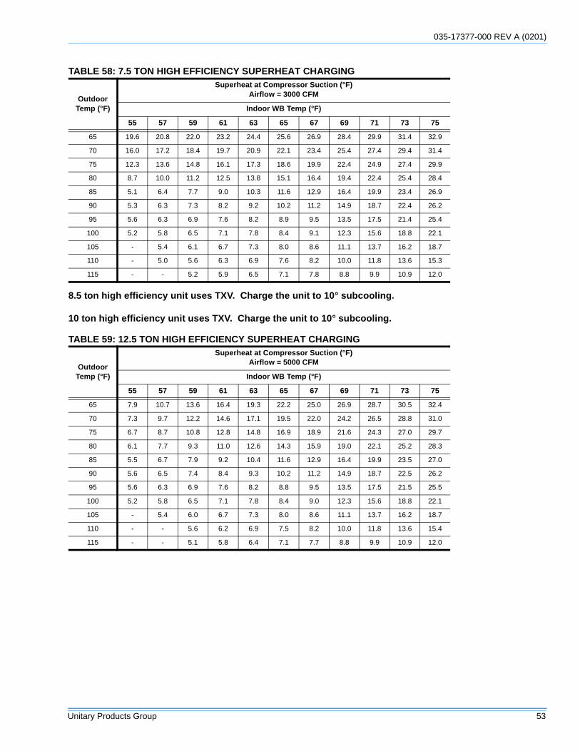
035-17377-000 REV A (0201)
Unitary Products Group 53
8.5 ton high efficiency unit uses TXV. Charge the unit to 10° subcooling.
10 ton high efficiency unit uses TXV. Charge the unit to 10° subcooling.
TABLE 58: 7.5 TON HIGH EFFICIENCY SUPERHEAT CHARGING
OutdoorTemp (°F)
Superheat at Compressor Suction (°F)Airflow = 3000 CFM
Indoor WB Temp (°F)
55 57 59 61 63 65 67 69 71 73 75
65 19.6 20.8 22.0 23.2 24.4 25.6 26.9 28.4 29.9 31.4 32.9
70 16.0 17.2 18.4 19.7 20.9 22.1 23.4 25.4 27.4 29.4 31.4
75 12.3 13.6 14.8 16.1 17.3 18.6 19.9 22.4 24.9 27.4 29.9
80 8.7 10.0 11.2 12.5 13.8 15.1 16.4 19.4 22.4 25.4 28.4
85 5.1 6.4 7.7 9.0 10.3 11.6 12.9 16.4 19.9 23.4 26.9
90 5.3 6.3 7.3 8.2 9.2 10.2 11.2 14.9 18.7 22.4 26.2
95 5.6 6.3 6.9 7.6 8.2 8.9 9.5 13.5 17.5 21.4 25.4
100 5.2 5.8 6.5 7.1 7.8 8.4 9.1 12.3 15.6 18.8 22.1
105 - 5.4 6.1 6.7 7.3 8.0 8.6 11.1 13.7 16.2 18.7
110 - 5.0 5.6 6.3 6.9 7.6 8.2 10.0 11.8 13.6 15.3
115 - - 5.2 5.9 6.5 7.1 7.8 8.8 9.9 10.9 12.0
TABLE 59: 12.5 TON HIGH EFFICIENCY SUPERHEAT CHARGING
OutdoorTemp (°F)
Superheat at Compressor Suction (°F)Airflow = 5000 CFM
Indoor WB Temp (°F)
55 57 59 61 63 65 67 69 71 73 75
65 7.9 10.7 13.6 16.4 19.3 22.2 25.0 26.9 28.7 30.5 32.4
70 7.3 9.7 12.2 14.6 17.1 19.5 22.0 24.2 26.5 28.8 31.0
75 6.7 8.7 10.8 12.8 14.8 16.9 18.9 21.6 24.3 27.0 29.7
80 6.1 7.7 9.3 11.0 12.6 14.3 15.9 19.0 22.1 25.2 28.3
85 5.5 6.7 7.9 9.2 10.4 11.6 12.9 16.4 19.9 23.5 27.0
90 5.6 6.5 7.4 8.4 9.3 10.2 11.2 14.9 18.7 22.5 26.2
95 5.6 6.3 6.9 7.6 8.2 8.8 9.5 13.5 17.5 21.5 25.5
100 5.2 5.8 6.5 7.1 7.8 8.4 9.0 12.3 15.6 18.8 22.1
105 - 5.4 6.0 6.7 7.3 8.0 8.6 11.1 13.7 16.2 18.7
110 - - 5.6 6.2 6.9 7.5 8.2 10.0 11.8 13.6 15.4
115 - - 5.1 5.8 6.4 7.1 7.7 8.8 9.9 10.9 12.0
035-17377-000 (0201) REV A
54 Unitary Products Group
NORMAL MAINTENANCE
GENERAL
FILTERS
Inspect once a month. Replace disposable or clean perma-nent type as necessary. DO NOT replace permanent typewith disposable.
MOTORS
Indoor fan and outdoor fan motors are permanently lubricatedand require no maintenance.
The draft motors on gas furnace units are factory lubricatedfor an estimated 10 years of life.
OUTDOOR COIL
Dirt should not be allowed to accumulate on the outdoor coilsurface or other parts in the air circuit. Cleaning should be asoften as necessary to keep coil clean. Use a brush, vacuumcleaner attachment, or other suitable means. If water is usedto clean coil, be sure power to the unit is shut off prior tocleaning. Service access is provided in the front and rearcondenser compartment panels to provide improved accessto the condenser coils.
NOTE: Exercise care when cleaning the coil so that the coilfins are not damaged. Do not permit the outdoor air dis-charge to be obstructed by overhanging structures of shrubs.
GAS FURNACE UNITS
BURNER
Periodically (at least annually at the beginning of each heat-ing season) make a visual check of the main burner flame. Ifit is not possible to adjust for the proper flame, the burnersmay need cleaning.
BURNER CLEANING
Remove the burners from the furnace as explained in“BURNER/ORIFICE INSTRUCTIONS”. Clean burners byapplying hot water along the top of the burners.
COMBUSTION AIR DISCHARGE
Visually inspect discharge outlet periodically to make surethat there is no buildup of soot and dirt. If necessary, cleanthe outlet to maintain adequate combustion air discharge.
CLEANING FLUE PASSAGES & HEATING ELEMENTS
With proper combustion adjustment, the heat exchangertubes of a gas-fired furnace will seldom need cleaning. If thetubes should become sooted, they can be cleaned as follows:
1. Remove the burner assembly as outlined in “BURNER/ORIFICES INSTRUCTIONS”.
2. Remove the screws holding the flue collector box. Care-fully remove the flue collector box.
3. Remove the flue baffles from the tube interiors.
4. Using a wire brush on a flexible wand, brush out the inside of each heat exchanger from the burner inlet and flue outlet ends.
5. Brush out the inside of the flue collector box and the flue baffles.
6. Run the wire brush into the flue exhaust tube from the flue collector end. Do not damage the flue exhaust screen, remove if necessary.
7. If soot build-up is particularly bad, remove the draft motor and clean the wheel and housing.
8. After brushing is complete, blow away all brushed areas with air or nitrogen. Vacuum as needed.
9. Replace parts in the reverse order that they were removed in Steps 1 through 3.
10. Assure that all seams on the vent side of the combustion system are airtight. Apply a high temperature (500°F+) sealing compound where needed.
Prior to any of the following maintenance proce-dures, shut off all power to the unit to prevent per-sonal injury.
Periodic maintenance normally consists of chang-ing or cleaning filters and (under some conditions)cleaning the main burners of gas furnace units.
Do not remove service panels or attempt to cleanthe interior of the condenser section when the unitis powered and/or operating. Shut off all power tothe unit prior to cleaning or maintenance of thecondenser section internals.
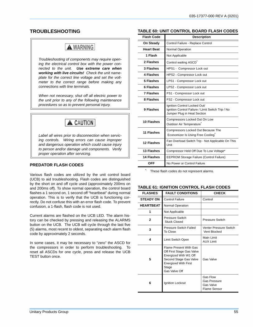
035-17377-000 REV A (0201)
Unitary Products Group 55
TROUBLESHOOTING
PREDATOR FLASH CODES
Various flash codes are utilized by the unit control board(UCB) to aid troubleshooting. Flash codes are distinguishedby the short on and off cycle used (approximately 200ms onand 200ms off). To show normal operation, the control boardflashes a 1 second on, 1 second off “heartbeat” during normaloperation. This is to verify that the UCB is functioning cor-rectly. Do not confuse this with an error flash code. To preventconfusion, a 1-flash, flash code is not used.
Current alarms are flashed on the UCB LED. The alarm his-tory can be checked by pressing and releasing the ALARMSbutton on the UCB. The UCB will cycle through the last five(5) alarms, most recent to oldest, separating each alarm flashcode by approximately 2 seconds.
In some cases, it may be necessary to “zero” the ASCD forthe compressors in order to perform troubleshooting. Toreset all ASCDs for one cycle, press and release the UCBTEST button once.
Troubleshooting of components may require open-ing the electrical control box with the power con-nected to the unit. Use extreme care whenworking with live circuits! Check the unit name-plate for the correct line voltage and set the volt-meter to the correct range before making anyconnections with line terminals.
When not necessary, shut off all electric power tothe unit prior to any of the following maintenanceprocedures so as to prevent personal injury.
Label all wires prior to disconnection when servic-ing controls. Wiring errors can cause improperand dangerous operation which could cause injuryto person and/or damage unit components. Verifyproper operation after servicing.
TABLE 60: UNIT CONTROL BOARD FLASH CODESFlash Code Description
On Steady Control Failure - Replace Control
Heart Beat Normal Operation
1 Flash Not Applicable
2 Flashes Control waiting ASCD*
3 Flashes HPS1 - Compressor Lock out
4 Flashes HPS2 - Compressor Lock out
5 Flashes LPS1 - Compressor Lock out
6 Flashes LPS2 - Compressor Lock out
7 Flashes FS1 - Compressor Lock out
8 Flashes FS2 - Compressor Lock out
9 FlashesIgnition Control Locked Out/Ignition Control Failure / Limit Switch Trip / No Jumper Plug in Heat Section
10 FlashesCompressors Locked Out On Low
Outdoor Air Temperature*
11 FlashesCompressors Locked Out Because The
Economizer Is Using Free Cooling*
12 FlashesFan Overload Switch Trip - Not Applicable On This Unit
13 Flashes Compressor Held Off Due To Low Voltage*
14 Flashes EEPROM Storage Failure (Control Failure)
OFF No Power or Control Failure
*. These flash codes do not represent alarms.
TABLE 61: IGNITION CONTROL FLASH CODESFLASHES FAULT CONDITIONS CHECK
STEADY ON Control Failure Control
HEARTBEAT Normal Operation
1 Not Applicable
2Pressure Switch Stuck Closed
Pressure Switch
3Pressure Switch FailedTo Close
Venter Pressure Switch Vent Blocked
4 Limit Switch OpenMain LimitAUX Limit
5
Flame Present With GasOff First Stage Gas ValveEnergized With W1 OffSecond Stage Gas ValveEnergized With First StageGas Valve Off
Gas Valve
6 Ignition Lockout
Gas FlowGas PressureGas ValveFlame Sensor
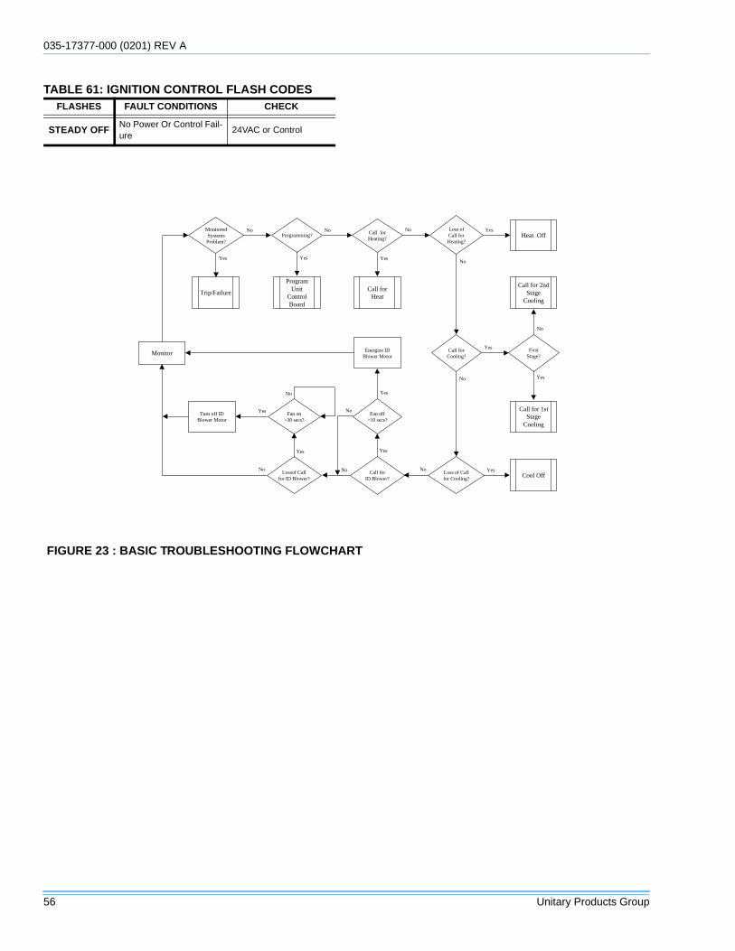
035-17377-000 (0201) REV A
56 Unitary Products Group
STEADY OFFNo Power Or Control Fail-ure
24VAC or Control
TABLE 61: IGNITION CONTROL FLASH CODESFLASHES FAULT CONDITIONS CHECK
FIGURE 23 : BASIC TROUBLESHOOTING FLOWCHART
Monitor
MonitoredSystems
Problem?
Call forCooling?
Call forHeating?
Call forHeat
Yes
No No No
Call for 1stStage
Cooling
FirstStage?
Call for 2ndStage
Cooling
Yes
Yes
Loss ofCall forHeating?
Loss of Callfor Cooling?
Heat Off
Cool Off
Yes
Yes
No
Call forID Blower?
Fan off>10 secs?
Energize IDBlower Motor
Yes
Yes
No
Programming?
ProgramUnit
ControlBoard
Trip/Failure
No
NoLossof Callfor ID Blower?
Turn off IDBlower Motor
Fan on>30 secs?
Yes
No
Yes
No
No
Yes
Yes
No
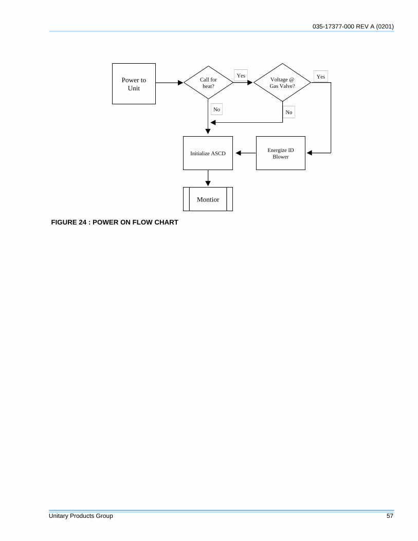
035-17377-000 REV A (0201)
Unitary Products Group 57
FIGURE 24 : POWER ON FLOW CHART
Power toUnit
Initialize ASCD
Call forheat?
Voltage @Gas Valve?
No No
Energize IDBlower
YesYes
Montior
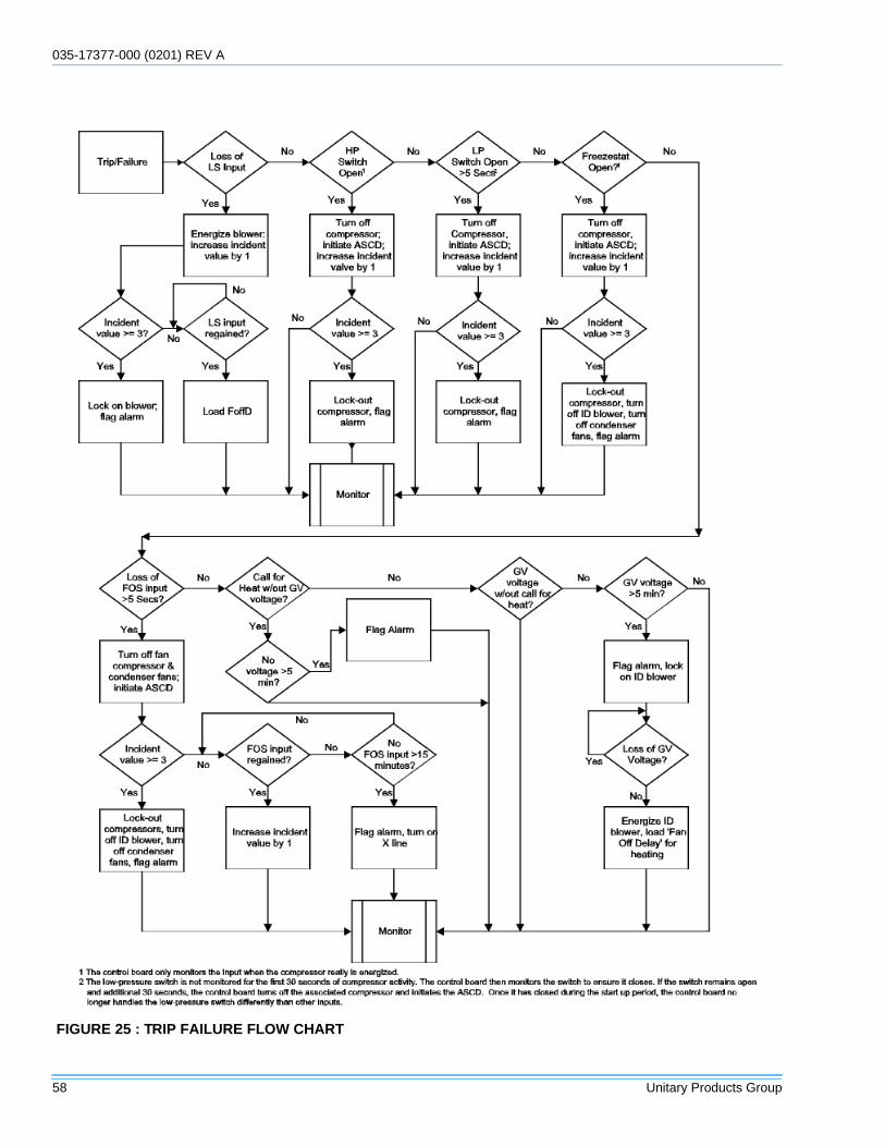
035-17377-000 (0201) REV A
58 Unitary Products Group
FIGURE 25 : TRIP FAILURE FLOW CHART
035-17377-000 REV A (0201)
Unitary Products Group 59
COOLING OPERATIONS
On calls for cooling, if the compressors are operating but thesupply air blower motor does not energize after a short delay(the room thermostat fan switch is in the “AUTO” position).
1. Turn the thermostat fan switch to the ON position. If the supply air blower motor does not energize, go to Step 3.
2. If the blower motor runs with the fan switch in the ON posi-tion but will not run after the first compressor has ener-gized when the fan switch is in the AUTO position, check the room thermostat for contact between R and G in the AUTO position during calls for cooling.
3. If the supply air blower motor does not energize when the fan switch is set to ON, check that line voltage is being supplied to the contacts of the M3, contactor, and that the contactor is pulled in. Check for loose wiring between the contactor and the supply air blower motor.
4. If M3 is pulled in and voltage is supplied to M3, lightly touch the supply air blower motor housing. If it is hot, the motor may be off on internal protection. Cancel any ther-mostat calls and set the fan switch to AUTO. Wait for the internal overload to reset. Test again when cool.
5. If M3 is not pulled in, check for 24 volts at the M3 coil. If 24 volts are present at M3 but M3 is not pulled in, replace the contactor.
6. Failing the above, if there is line voltage supplied at M3, M3 is pulled in, and the supply air blower motor still does not operate, replace the motor.
7. If 24 volts is not present at M3, check that 24 volts is present at the UCB supply air blower motor terminal, “FAN”. If 24 volts is present at the FAN, check for loose wiring between the UCB and M3.
8. If 24 volts is not present at the “FAN” terminal, check for 24 volts from the room thermostat. If 24 volts are not present from the room thermostat, check for the following:
a. proper operation of the room thermostat (contactbetween R and G with the fan switch in the ON posi-tion and in the AUTO position during operation calls),b. proper wiring between the room thermostat and theUCB, and c. loose wiring from the room thermostat tothe UCB.
9. If 24 volts is present at the room thermostat but not at the UCB, check for proper wiring between the thermostat and the UCB, i.e. that the thermostat G terminal is connected to the G terminal of the UCB, and for loose wiring.
10. If the thermostat and UCB are properly wired, replace the UCB.
On calls for cooling, the supply air blower motor is operatingbut compressor #1 is not (the room thermostat fan switch is inthe “AUTO” position).
1. If installed, check the position of the economizer blades. If the blades are open, the economizer is providing free cooling and the compressors will not immediately operate. If both stages of cooling are requested simultaneously and the economizer provides free cooling, following a short delay compressor #1 will be energized unless it is locked out. If compressor #1 is locked out, compressor #2 is energized. Compressor #2 is always energized in place of compressor #1 when compressor #1 is requested but locked out.
2. If no economizer is installed or the economizer is not opening to provide free cooling and compressor #1 does not energize on a call for cooling, check for line voltage at the compressor contactor, M1, and that the contactor is pulled in. Check for loose wiring between the contactor and the compressor.
3. If M1 is pulled in and voltage is supplied at M1, lightly touch the compressor housing. If it is hot, the compressor may be off on inherent protection. Cancel any calls for cooling and wait for the internal overload to reset. Test again when cool.
4. If M1 is not pulled in, check for 24 volts at the M1 coil. If 24 volts are present and M1 is not pulled in, replace the contactor.
5. Failing the above, if voltage is supplied at M1, M1 is pulled in, and the compressor still does not operate, replace the compressor.
6. If 24 volts is not present at M1, check for 24 volts at the UCB terminal, C1. If 24 volts is present, check for loose wiring between C1 and the compressor contactor.
7. If 24 volts is not present at the C1 terminal, check for 24 volts from the room thermostat at the UCB Y1 terminal. If 24 volts is not present from the room thermostat, check for the following: a) 24 volts at the thermostat Y1 terminal, b) proper wiring between the room thermostat and the UCB, i.e. Y1 to Y1, Y2 to Y2, and c) loose wiring from the room thermostat to the UCB.
8. If 24 volts is present at the UCB Y1 terminal, the compres-sor may be out due to an open high-pressure switch, low-pressure switch, or freezestat. Check for 24 volts at the HPS1, LPS1, and FS1 terminals of the UCB. If a switch has opened, there should be a voltage potential between the UCB terminals, e.g. if LPS1 has opened, there will be a 24-volt potential between the LPS1 terminals.
9. If 24 volts is present at the UCB Y1 terminal and none of the protection switches have opened, the UCB may have locked out the compressor for repeat trips. The UCB
035-17377-000 (0201) REV A
60 Unitary Products Group
should be flashing an alarm code. If not, press and release the ALARMS button on the UCB. The UCB will flash the last five alarms on the LED. If the compressor is locked out, cancel any call for cooling. This will reset any compressor lock outs.
NOTE: While the above step will reset any lockouts, compres-sor #1 may be held off for the ASCD. See the next step.
10. If 24 volts is present at the UCB Y1 terminal and none of the switches are open and the compressor is not locked out, the UCB may have the compressor in an ASCD. Check the LED for an indication of an ASCD cycle. The ASCD should time out within 5 minutes. Press and release the TEST button to reset all ASCDs.
11. If 24 volts is present at the UCB Y1 terminal and the com-pressor is not out due to a protective switch trip, repeat trip lock out, or ASCD, the economizer terminals of the UCB may be improperly wired. Check for 24 volts at the Y1 “OUT” terminal of the UCB. If 24 volts is present, trace the wiring from Y1 “OUT” for incorrect wiring. If 24 volts is not present at the Y1 “OUT” terminal, the UCB must be replaced.
12. For units without economizers:If 24 volts is present at the Y1 OUT terminal, check for 24 volts at the Y1 “ECON” ter-minal. If 24 volts is not present, check for loose wiring from the Y1 “OUT” terminal to the Mate-N-Lock plug, the jumper in the Mate-N-Lock plug, and in the wiring from the Mate-N-Lock plug to the Y1 “ECON” terminal.
13. For units with economizers: If 24 volts is present at the Y1 “OUT” terminal, check for 24 volts at the Y1 “ECON” termi-nal. If 24 volts is not present, check for loose wiring from the Y1 “OUT” terminal to the Mate-N-Lock plug, a poor connection between the UCB and economizer Mate-N-Lock plugs, loose wiring from the Mate-N-Lock plug to the economizer, back to the Mate-N-Lock plug, and from the Mate-N-Lock plug to the Y1 “ECON” terminal. If nothing is found, the economizer DME may have faulted and is fail-ing to return the 24-volt “call” to the Y1 “ECON” terminal even though the economizer is not providing free cooling. To test, disconnect the Mate-N-Locks and jumper between the WHITE and YELLOW wires of the UCB’s Mate-N-Lock plug. If compressor #1 energizes, there is a fault in the economizer wiring or DME.
14. The UCB can be programmed to lock out compressor operation during free cooling and in low ambient condi-tions. These options are not enabled by default. Local York distributors can test the UCB for this programming.
15. If none of the above corrected the error, test the integrity of the UGB. Disconnect the C1 terminal wire and jumper it to the Y1 terminal. DO NOT jump the Y1 to C1 terminals. If the compressor engages, the UCB has faulted.
16. If none of the above correct the error, replace the UCB.
On calls for the second stage of cooling, the supply air blowermotor and compressor #1 are operating but compressor #2 isnot (the room thermostat fan switch is in the “AUTO” position).
1. If installed, check the position of the economizer blades. If the blades are open, the economizer is providing free cooling. If the second stage of cooling is requested, fol-lowing a short delay, compressor #1 will be energized unless it is locked out. Typically, compressor #2 is ener-gized only during free cooling if the call for the second stage of cooling persists for 20 minutes.
2. Compressor #2 will not energize simultaneously with com-pressor #1 if a call for both stages of cooling is received. The UCB delays compressor #2 by 30 seconds to prevent a power surge. If after the delay compressor #2 does not energize on a second stage call for cooling, check for line voltage at the compressor contactor, M2, and that the con-tactor is pulled in. Check for loose wiring between the contactor and the compressor.
3. If M2 is pulled in and voltage is supplied at M2, lightly touch the compressor housing. If it is hot, the compressor may be off on inherent protection. Cancel any calls for cooling and wait for the internal overload to reset. Test again when cool.
4. If M2 is not pulled in, check for 24 volts at the M2 coil. If 24 volts is present and M2 is not pulled in, replace the contactor.
5. Failing the above, if voltage is supplied at M2, M2 is pulled in, and the compressor still does not operate, replace the compressor.
6. If 24 volts is not present at M2, check for 24 volts at the UCB terminal, C2. If 24 volts are present, check for loose wiring between C2 and the compressor contactor.
7. If 24 volts is not present at the C2 terminal, check for 24 volts from the room thermostat at the UCB Y2 terminal. If 24 volts is not present from the room thermostat, check for the following: a) 24 volts at the thermostat Y2 terminal, b) proper wiring between the room thermostat and the UCB, i.e. Y1 to Y1, Y2 to Y2, and c) loose wiring from the room thermostat to the UCB.
8. If 24 volts is present at the UCB Y2 terminal, the compres-sor may be out due to an open high-pressure switch, low-pressure switch, or freezestat. Check for 24 volts at the HPS2, LPS2, and FS2 terminals of the UCB. If a switch has opened, there should be a voltage potential between the UCB terminals, e.g. if LPS2 has opened, there will be 24 volts of potential between the LPS2 terminals.
9. If 24 volts is present at the UCB Y2 terminal and none of the protection switches have opened, the UCB may have locked out the compressor for repeat trips. The UCB should be flashing a code. If not, press and release the
035-17377-000 REV A (0201)
Unitary Products Group 61
ALARMS button on the UCB. The UCB will flash the last five alarms on the LED. If the compressor is locked out, remove any call for cooling at the thermostat or by discon-necting the thermostat wiring at the Y2 UCB terminal. This will reset any compressor lock outs.
NOTE: While the above step will reset any lock outs, compres-sor #1 will be held off for the ASCD, and compressor #2 maybe held off for a portion of the ASCD. See the next step.
10. If 24 volts is present at the UCB Y2 terminal and none of the switches are open and the compressor is not locked out, the UCB may have the compressor in an ASCD. Check the LED for an indication of an ASCD cycle. The ASCD should time out within 5 minutes. Press and release the TEST button to reset all ASCDs.
11. The UCB can be programmed to lock out compressor operation during free cooling and in low ambient condi-tions. These options are not enabled by default. Local York distributors can test the UCB for this programming.
12. If none of the above corrected the error, test the integrity of the UGB. Disconnect the C2 terminal wire and jumper it to the Y2 terminal. DO NOT jump the Y2 to C2 terminals. If the compressor engages, the UCB has faulted.
13. If none of the above correct the error, replace the UCB.
On a call for cooling, the supply air blower motor and compres-sor #2 are operating but compressor #1 is not (the room ther-mostat fan switch is in the “AUTO” position).
1. Compressor #2 is energized in place of compressor #1 when compressor #1 is unavailable for cooling calls. Check the UCB for alarms indicating that compressor #1 is locked out. Press and release the ALARMS button if the LED is not flashing an alarm.
2. Check for line voltage at the compressor contactor, M1, and that the contactor is pulled in. Check for loose wiring between the contactor and the compressor.
3. If M1 is pulled in and voltage is supplied at M1, lightly touch the compressor housing. If it is hot, the compressor may be off on inherent protection. Cancel any calls for cooling and wait for the internal overload to reset. Test again when cool.
4. If M1 is not pulled in, check for 24 volts at the M1 coil. If 24 volts is present and M1 is not pulled in, replace the contactor.
5. Failing the above, if voltage is supplied at M1, M1 is pulled in, and the compressor still does not operate, replace the compressor.
6. If 24 volts is not present at M1, check for 24 volts at the UCB terminal, C1. If 24 volts is present, check for loose wiring between C1 and the compressor contactor.
7. If 24 volts is not present at the C1 terminal, check for 24 volts from the room thermostat at the UCB Y1 terminal. If 24 volts are not present at the UCB Y1 terminal, the UCB may have faulted. Check for 24 volts at the Y1 ECON ter-minal. If 24 volts is not present at Y1 “ECON”, the UCB has faulted. The UCB should de-energize all compressors on a loss of call for the first stage of cooling, i.e. a loss if 24 volts at the Y1 terminal.
8. If 24 volts are present at the UCB Y1 terminal, the com-pressor may be out due to an open high-pressure switch, low-pressure switch, or freezestat. Check for 24 volts at the HPS1, LPS1, and FS1 terminals of the UCB. If a switch has opened, there should be a voltage potential between the UCB terminals, e.g. if LPS1 has opened, there will be a 24-volt potential between the LPS1 termi-nals.
9. If 24 volts is present at the UCB Y1 terminal and none of the protection switches have opened, the UCB may have locked out the compressor for repeat trips. The UCB should be flashing a code. If not, press and release the ALARMS button on the UCB. The UCB will flash the last five alarms on the LED. If the compressor is locked out, remove any call for cooling. This will reset any compres-sor lock outs.
NOTE: While the above step will reset any lock outs, compres-sor #2 will be held off for the ASCD, and compressor #1 maybe held off for a portion of the ASCD. See the next step.
10. If 24 volts is present at the UCB Y1 terminal and none of the switches are open and the compressor is not locked out, the UCB may have the compressor in an ASCD. Check the LED for an indication of an ASCD cycle. The ASCD should time out within 5 minutes. Press and release the TEST button to reset all ASCDs.
11. If 24 volts is present at the UCB Y1 terminal and the com-pressor is not out due to a protective switch trip, repeat trip lock out, or ASCD, the economizer terminals of the UCB may be improperly wired. Check for 24 volts at the Y1 “OUT” terminal of the UCB. If 24 volts is present, trace the wiring from Y1 “OUT” for incorrect wiring. If 24 volts is not present at the Y1 “OUT” terminal, the UCB must be replaced.
12. For units without economizers: If 24 volts is present at the Y1 “OUT” terminal, check for 24 volts at the Y1 “ECON” terminal. If 24 volts is not present, check for loose wiring from the Y1 “OUT” terminal to the Mate-N-Lock plug, the jumper in the Mate-N-Lock plug, and in the wiring from the Mate-N-Lock plug to the Y1 “ECON” terminal.
035-17377-000 (0201) REV A
62 Unitary Products Group
For units with economizers:If 24 volts is present at the Y1 “OUT” terminal, check for 24 volts at the Y1 “ECON” termi-nal. If 24 volts is not present, check for loose wiring from the Y1 “OUT” terminal to the Mate-N-Lock plug, a poor connection between the UCB and economizer Mate-N-Lock plugs, loose wiring from the Mate-N-Lock plug to the economizer, back to the Mate-N-Lock plug, and from the Mate-N-Lock plug to the Y1 “ECON” terminal. The econo-mizer board may have faulted and is not returning the 24 volts to the Y1 “ECON” terminal even though the econo-mizer is not providing free cooling. To test the economizer board, disconnect the Mate-N-Locks and jumper between the WHITE and YELLOW wires of the UCB’s Mate-N-Lock plug.
13. The UCB can be programmed to lock out compressor operation during free cooling and in low ambient condi-tions. These options are not enabled by default. They can be checked by local York distributors.
14. If none of the above corrected the error, test the integrity of the UGB. Disconnect the C1 terminal wire and jumper it to the Y1 terminal. DO NOT jump the Y1 to C1 terminals. If the compressor engages, the UCB has faulted.
15. If none of the above correct the error, replace the UCB.
GAS FURNACE OPERATIONS
On calls for heating, the draft motor operates and the furnacelights but the supply air blower motor does not energize after ashort delay (the room thermostat fan switch is in “AUTO” posi-tion).
1. Place the thermostat fan switch in the “ON” position. If the supply air blower motor energizes, go to Step 9.
2. If the supply air blower motor does not energize when the fan switch is set to “ON,” check that line voltage is being supplied to the contacts of the M3 contactor, and that the contactor is pulled in. Check for loose wiring between the contactor and the supply air blower motor.
3. If M3 is pulled in and voltage is supplied at M3, lightly touch the supply air blower motor housing. If it is hot, the motor may be off on inherent protection. Cancel any ther-
mostat calls and set the fan switch to “AUTO”, wait for the internal overload to reset. Test again when cool.
4. If M3 is not pulled in, check for 24 volts at the M3 coil. If 24 volts is present at M3 but M3 is not pulled in, replace the contactor.
5. Failing the above, if there is line voltage supplied at M3, M3 is pulled in, and the supply air blower motor still does not operate, replace the motor.
6. If 24 volts is not present at M3, check that 24 volts is present at the supply air blower motor terminal on the UCB. If 24 volts is present at the UCB terminal, check for loose wiring between the UCB and M3.
a. If 24 volts is not present at the UCB supply air blowermotor terminal, check for 24 volts from the room ther-mostat. If 24 volts is not present from the room ther-mostat, check for the following:proper operation of the room thermostat (contactbetween R and G with the fan switch in the “ON” posi-tion and in the “AUTO” position during operationcalls), b) proper wiring between the room thermostatand the UCB, and c) loose wiring from the room ther-mostat to the UCB.
7. If 24 volts is present at the room thermostat but not at the UCB, check for proper wiring between the thermostat and the UCB, i.e. that the thermostat G terminal is connected to the G terminal of the UCB, and for loose wiring.
8. If the thermostat and UCB are properly wired, replace the UCB.
9. If the blower motor runs with the fan switch in the “ON” position but does not run shortly after the furnace has ignited when the fan switch is in the “AUTO” position, check the room thermostat for contact between R and G during “W1” calls.
On calls for heating, the supply air blower operates but thedraft motor does not (the room thermostat fan switch is in the“AUTO” position).
1. The draft motor has inherent protection. If the motor shell is hot to the touch, wait for the internal overload to reset.
2. If the motor shell is cold with the room thermostat calling for heat, check for line voltage at the motor leads. If line voltage is present, replace the draft motor.
3. If line voltage is not present, check for line voltage on the ignition control at the “inducer” terminal draft motor relay (DMR or DMC) contacts in the main control box and check to see if the (DMR or DMC) is pulled in.
The draft motor runs but the furnace does not light and thespark ignitor does not spark.
The furnace may shut down on a high temperaturecondition during the procedure. If this occurs, theUCB energize the supply air blower motor until thehigh temperature limit has reset. Caution shouldbe used at all times as the supply air blower mayenergize regardless of the room thermostat fanswitch position.
035-17377-000 REV A (0201)
Unitary Products Group 63
1. Check for 24 volts at the spark ignitor from the ignition control board (ICB). Check the 24-volt wiring from the ICB to the spark ignitor. Check for 24 volts at the ICB spark ignitor terminal.
2. Check the ground wiring for the ICB and the gas valve is intact and making good electrical connection. Check the ceramic insulator on the spark ignitor for breaks or cracks. Replace the spark ignitor if damaged.
3. With the draft motor running, check for 24 volts at the pressure switch terminal on the ICB. If not present, check for 24 volts on the terminal from the pressure switch. If present, go to step 4. If 24 volts is not present, the either pressure or rollout switch is not closed. Or the draft motor is not sufficiently evacuating the heat exchanger tubes or the pressure switch has failed. Check the operation of the pressure switch. Check the line voltage to the unit; if line voltage is low, call the local power company. If the prob-lem persists, the draft motor may need replacement.
4. If the furnace is hot, it may be out on a high temperature limit open; wait for limit reset.
5. If all are intact replace the ICB.
The draft motor runs and the spark ignitor sparks at the burner,but the burner does not ignite and a gas odor is not detected atthe draft motor outlet.
1. Check to ensure gas is being supplied to the unit. Confirm that the gas pressure to the unit is within the proper limits as described in the “POST START CHECKLIST”.
2. Check the voltage at the gas valve and at the gas valve terminals on the ICB. Check all wiring between the ICB and the gas valve. Check to make sure the ground con-nections are intact.
3. If 24 volts is present, remove the pilot burner and the ori-fice. The removal procedure is described in “BURNER/ORIFICE INSTRUCTIONS.” Inspect the orifice for obstruction. If it is clear, replace the gas valve.
Main burners light but exhibit erratic flame characteristics.
4. Check the main burner orifices for obstruction and align-ment. The removal procedure is described in “BURNER/ORIFICE INSTRUCTIONS.” Clean or replace burner orifices and burners as needed.
Subject to change without notice. Printed in U.S.A. CD-17377 Supersedes: 035-17240-000 Rev B (0101) Copyright © by Unitary Products Group 2001. All rights reserved. 035-17377-000 A (0201)
Unitary 5005 NormanProducts York OKGroup Drive 73069
NOTES
035-17377-000 REV A (0201)
Unitary Products Group 65
GENERAL . . . . . . . . . . . . . . . . . . . . . . . . . . . . . . . . .6
SAFETY CONSIDERATIONS . . . . . . . . . . . . . . . . . .6
NOTES CAUTIONS AND WARNINGS . . . . . . . . . . .6
APPROVALS . . . . . . . . . . . . . . . . . . . . . . . . . . . . . . .6
REFERENCE . . . . . . . . . . . . . . . . . . . . . . . . . . . . . . .6
INSPECTION . . . . . . . . . . . . . . . . . . . . . . . . . . . . . . .7
INSTALLATION . . . . . . . . . . . . . . . . . . . . . . . . . . . . .7PRECEDING INSTALLATION . . . . . . . . . . . . . . . . . . . . . 7LIMITATIONS . . . . . . . . . . . . . . . . . . . . . . . . . . . . . . . . . . 8LOCATION . . . . . . . . . . . . . . . . . . . . . . . . . . . . . . . . . . . . 9RIGGING AND HANDLING . . . . . . . . . . . . . . . . . . . . . . . 9CLEARANCES . . . . . . . . . . . . . . . . . . . . . . . . . . . . . . . . 10DUCTWORK . . . . . . . . . . . . . . . . . . . . . . . . . . . . . . . . . . 14DUCT COVERS . . . . . . . . . . . . . . . . . . . . . . . . . . . . . . . 15CONDENSATE DRAIN . . . . . . . . . . . . . . . . . . . . . . . . . . 16COMPRESSORS . . . . . . . . . . . . . . . . . . . . . . . . . . . . . . 16FILTERS . . . . . . . . . . . . . . . . . . . . . . . . . . . . . . . . . . . . . 16THERMOSTAT WIRING . . . . . . . . . . . . . . . . . . . . . . . . . 16POWER AND CONTROL WIRING . . . . . . . . . . . . . . . . . 16POWER WIRING DETAIL . . . . . . . . . . . . . . . . . . . . . . . 17GAS HEAT . . . . . . . . . . . . . . . . . . . . . . . . . . . . . . . . . . . 26
LP UNITS, TANKS AND PIPING . . . . . . . . . . . . . . . . . . . . . . . 26GAS PIPING . . . . . . . . . . . . . . . . . . . . . . . . . . . . . . . . . . . . . . 26GAS CONNECTION . . . . . . . . . . . . . . . . . . . . . . . . . . . . . . . . 27VENT AND COMBUSTION AIR . . . . . . . . . . . . . . . . . . . . . . . 27
ACCESSORIES . . . . . . . . . . . . . . . . . . . . . . . . . . . .27ELECTRIC HEAT . . . . . . . . . . . . . . . . . . . . . . . . . . . . . . 27ECONOMIZER . . . . . . . . . . . . . . . . . . . . . . . . . . . . . . . . 28RAIN HOOD . . . . . . . . . . . . . . . . . . . . . . . . . . . . . . . . . . 28SET POINT ADJUSTMENT . . . . . . . . . . . . . . . . . . . . . . 28
START-UP . . . . . . . . . . . . . . . . . . . . . . . . . . . . . . . .29PHASING . . . . . . . . . . . . . . . . . . . . . . . . . . . . . . . . . . . . 29SUPPLY AIR INSTRUCTIONS . . . . . . . . . . . . . . . . . . . . 29
CHECKING SUPPLY AIR CFM . . . . . . . . . . . . . . . . . . . . . . . . 29
BLOWER ROTATION . . . . . . . . . . . . . . . . . . . . . . . . . . . 29BELT TENSION . . . . . . . . . . . . . . . . . . . . . . . . . . . . . . . 30AIR BALANCE . . . . . . . . . . . . . . . . . . . . . . . . . . . . . . . . 41CHECKING AIR QUANTITY . . . . . . . . . . . . . . . . . . . . . . 41SUPPLY AIR DRIVE ADJUSTMENT . . . . . . . . . . . . . . . 42
GAS FURNACE OPERATION . . . . . . . . . . . . . . . . .43BURNERS/ORIFICES INSPECTION/SERVICING . . . . 43
LIGHTING THE MAIN BURNERS . . . . . . . . . . . . . . . . . . . . . . 43
POST START CHECKLIST . . . . . . . . . . . . . . . . . . . . . . 44SHUT DOWN . . . . . . . . . . . . . . . . . . . . . . . . . . . . . . . . . 44MANIFOLD GAS PRESSURE ADJUSTMENT . . . . . . . . 44ADJUSTMENT OF TEMPERATURE RISE . . . . . . . . . . 44CHECKING GAS INPUT . . . . . . . . . . . . . . . . . . . . . . . . 44
NATURAL GAS . . . . . . . . . . . . . . . . . . . . . . . . . . . . . . . . . . . . 44
COOLING OPERATION INSTRUCTIONS . . . . . . .46COOLING SYSTEM PRELIMINARY OPERATION . . . . 46TURN ON THE POWER TO THE UNIT . . . . . . . . . . . . . 46POST START CHECK LIST . . . . . . . . . . . . . . . . . . . . . . 46
PROPER SYSTEM PRESSURES FOR BOTH CIRCUITS . . .46SHUT DOWN . . . . . . . . . . . . . . . . . . . . . . . . . . . . . . . . . . . . . .46
SEQUENCE OF OPERATIONS . . . . . . . . . . . . . . . .46OVERVIEW . . . . . . . . . . . . . . . . . . . . . . . . . . . . . . . . . . 46SAFETY CONTROLS . . . . . . . . . . . . . . . . . . . . . . . . . . 46PROTECTION . . . . . . . . . . . . . . . . . . . . . . . . . . . . . . . . 47CONTINUOUS BLOWER . . . . . . . . . . . . . . . . . . . . . . . . 47INTERMITTENT BLOWER . . . . . . . . . . . . . . . . . . . . . . 47COOLING SEQUENCE OF OPERATION . . . . . . . . . . . 47COOLING OPERATION ERRORS . . . . . . . . . . . . . . . . 47
HIGH-PRESSURE LIMIT SWITCH . . . . . . . . . . . . . . . . . . . . .47LOW-PRESSURE LIMIT SWITCH . . . . . . . . . . . . . . . . . . . . . .47FREEZESTAT . . . . . . . . . . . . . . . . . . . . . . . . . . . . . . . . . . . . .48FLASH CODES . . . . . . . . . . . . . . . . . . . . . . . . . . . . . . . . . . . .48RESET . . . . . . . . . . . . . . . . . . . . . . . . . . . . . . . . . . . . . . . . . . .48
GAS HEATING SEQUENCE OF OPERATIONS . . . . . . 48IGNITION CONTROL BOARD . . . . . . . . . . . . . . . . . . . . 48
FIRST STAGE OF HEATING . . . . . . . . . . . . . . . . . . . . . . . . . .48SECOND STAGE OF HEATING . . . . . . . . . . . . . . . . . . . . . . .48RETRY OPERATION . . . . . . . . . . . . . . . . . . . . . . . . . . . . . . . .48RECYCLE OPERATION . . . . . . . . . . . . . . . . . . . . . . . . . . . . .48
GAS HEATING OPERATION FAULTS . . . . . . . . . . . . . 48LOCK-OUT . . . . . . . . . . . . . . . . . . . . . . . . . . . . . . . . . . . . . . . .48TEMPERATURE LIMIT . . . . . . . . . . . . . . . . . . . . . . . . . . . . . .48FLAME SENSE . . . . . . . . . . . . . . . . . . . . . . . . . . . . . . . . . . . .49GAS VALVE . . . . . . . . . . . . . . . . . . . . . . . . . . . . . . . . . . . . . . .49PRESSURE SWITCH . . . . . . . . . . . . . . . . . . . . . . . . . . . . . . .49ROLLOUT SWITCH . . . . . . . . . . . . . . . . . . . . . . . . . . . . . . . . .49INTERNAL MICROPROCESSOR FAILURE . . . . . . . . . . . . . .49
LOW AMBIENT COOLING . . . . . . . . . . . . . . . . . . . . . . . 49
NORMAL MAINTENANCE . . . . . . . . . . . . . . . . . . .54GENERAL . . . . . . . . . . . . . . . . . . . . . . . . . . . . . . . . . . . 54
FILTERS . . . . . . . . . . . . . . . . . . . . . . . . . . . . . . . . . . . . . . . . .54MOTORS . . . . . . . . . . . . . . . . . . . . . . . . . . . . . . . . . . . . . . . . .54OUTDOOR COIL . . . . . . . . . . . . . . . . . . . . . . . . . . . . . . . . . . .54
GAS FURNACE UNITS . . . . . . . . . . . . . . . . . . . . . . . . . 54BURNER . . . . . . . . . . . . . . . . . . . . . . . . . . . . . . . . . . . . . . . . .54BURNER CLEANING . . . . . . . . . . . . . . . . . . . . . . . . . . . . . . . .54COMBUSTION AIR DISCHARGE . . . . . . . . . . . . . . . . . . . . . .54CLEANING FLUE PASSAGES & HEATING ELEMENTS . . . .54
TROUBLESHOOTING . . . . . . . . . . . . . . . . . . . . .55PREDATOR FLASH CODES . . . . . . . . . . . . . . . . . . . . . 55
COOLING OPERATIONS . . . . . . . . . . . . . . . . . . . .58
GAS FURNACE OPERATIONS . . . . . . . . . . . . . . .61
035-17377-000 REV A (0201)
66 Unitary Products Group
035-17377-000 REV A (0201)
Unitary Products Group 67
1 UNIT SHIPPING BRACKET . . . . . . . . . . . . . . . . .7
2 CONDENSER COVERING . . . . . . . . . . . . . . . . .7
3 COMPRESSOR SECTION . . . . . . . . . . . . . . . . .7
4 PREDATOR™ COMPONENT LOCATION . . . . .8
5 UNIT 4 POINT LOAD . . . . . . . . . . . . . . . . . . . . . .9
6 UNIT CENTER OF GRAVITY . . . . . . . . . . . . . .10
7 UNIT 6 POINT LOAD . . . . . . . . . . . . . . . . . . . . .10
8 UNIT DIMENSIONS . . . . . . . . . . . . . . . . . . . . . .12
9 BOTTOM DUCT OPENINGS (FROM ABOVE) . . . . . . . . . . . . . . . . . . . . . . . . .13
10 REAR DUCT DIMENSIONS . . . . . . . . . . . . . . .14
11 PREDATOR™ ROOF CURB DIMENSIONS . . .15
12 SUNLINE™ TO PREDATOR™ TRANSITION ROOF CURBS . . . . . . . . . . . . . . . . . . . . . . . . . .15
13 CONDENSATE DRAIN . . . . . . . . . . . . . . . . . . .16
14 ELECTRONIC THERMOSTAT FIELD WIRING . . . . . . . . . . . . . . . . . . . . . . . . . . . . . . .17
15 FIELD WIRING 24 VOLT THERMOSTAT . . . . .18
16 FIELD WIRING DISCONNECT . . . . . . . . . . . . .19
17 SIDE ENTRY GAS PIPING . . . . . . . . . . . . . . . .26
18 BOTTOM ENTRY GAS PIPING . . . . . . . . . . . . .26
19 ENTHALPY SET POINT CHART . . . . . . . . . . . .28
20 BELT ADJUSTMENT . . . . . . . . . . . . . . . . . . . . .30
21 TYPICAL FLAME . . . . . . . . . . . . . . . . . . . . . . . .43
22 TYPICAL GAS VALVE . . . . . . . . . . . . . . . . . . . .43
23 BASIC TROUBLESHOOTING FLOWCHART . . . . . . . . . . . . . . . . . . . . . . . . . .56
24 POWER ON FLOW CHART . . . . . . . . . . . . . . .56
25 TRIP FAILURE FLOW CHART . . . . . . . . . . . . .57

035-17377-000 REV A (0201)
68 Unitary Products Group
035-17377-000 REV A (0201)
Unitary Products Group 69
1 PRODUCT NOMENCLATURE . . . . . . . . . . . . . .5
2 AIRFLOW ABBREVIATIONS . . . . . . . . . . . . . . . .5
3 INSTALLATION ABBREVIATIONS . . . . . . . . . . .5
4 ADDITIONAL OPTIONS ABBREVIATIONS . . . .5
5 UNIT VOLTAGE LIMITATIONS . . . . . . . . . . . . . .8
6 UNIT TEMPERATURE LIMITATIONS . . . . . . . . .9
7 UNIT WEIGHTS . . . . . . . . . . . . . . . . . . . . . . . . . .9
8 4 POINT LOAD WEIGHT . . . . . . . . . . . . . . . . . .10
9 6 POINT LOAD WEIGHT . . . . . . . . . . . . . . . . . .10
10 UNIT CLEARANCES . . . . . . . . . . . . . . . . . . . . .12
11 CONTROL WIRE SIZES . . . . . . . . . . . . . . . . . .16
12 ELECTRICAL DATA 6-1/2 TON - STANDARD EFFICIENCY . . . . . . . . . . . . . . . . . . . . . . . . . . .19
13 ELECTRICAL DATA 6-1/2 TON - HIGH EFFICIENCY . . . . . . . . . . . . . . . . . . . . . . . . . . .20
14 ELECTRICAL DATA 7-1/2 TON - STANDARD EFFICIENCY . . . . . . . . . . . . . . . . . . . . . . . . . . .20
15 ELECTRICAL DATA 7-1/2 TON - HIGH EFFICIENCY . . . . . . . . . . . . . . . . . . . . . . . . . . .21
16 ELECTRICAL DATA 8-1/2 TON - STANDARD EFFICIENCY . . . . . . . . . . . . . . . . . . . . . . . . . . .21
17 ELECTRICAL DATA 8-1/2 TON - HIGH EFFICIENCY . . . . . . . . . . . . . . . . . . . . . . . . . . .22
18 ELECTRICAL DATA 10 TON - STANDARD EFFICIENCY . . . . . . . . . . . . . . . . . . . . . . . . . . .22
19 ELECTRICAL DATA 10 TON - HIGH EFFICIENCY . . . . . . . . . . . . . . . . . . . . . . . . . . .23
20 ELECTRICAL DATA 12-1/2 TON - STANDARD EFFICIENCY . . . . . . . . . . . . . . . . . . . . . . . . . . .23
21 ELECTRICAL DATA 12-1/2 TON - HIGH EFFICIENCY . . . . . . . . . . . . . . . . . . . . . . . . . . .24
22 PHYSICAL DATA . . . . . . . . . . . . . . . . . . . . . . . .24
23 GAS HEAT LIMIT SETTINGS . . . . . . . . . . . . . .26
24 GAS PIPE SIZING - CAPACITY OF PIPE . . . . .27
25 ACCESSORY STATIC RESISTANCE . . . . . . . .29
26 SUPPLY AIR LIMITATIONS . . . . . . . . . . . . . . .29
27 6-1/2 TON STANDARD MOTOR DOWN SHOT BLOWER PERFORMANCE . . . . . . . . . .31
28 6-1/2 TON OPTIONAL MOTOR DOWN SHOT BLOWER PERFORMANCE . . . . . . . . . . . . . . .31
29 7-1/2 TON STANDARD MOTOR DOWN SHOT BLOWER PERFORMANCE . . . . . . . . . . . . . . .32
30 7-1/2 TON OPTIONAL MOTOR DOWN SHOT BLOWER PERFORMANCE . . . . . . . . . . . . . . .32
31 8-1/2 TON STANDARD MOTOR DOWN SHOT BLOWER PERFORMANCE 33
32 8-1/2 TON OPTIONAL MOTOR DOWN SHOT BLOWER PERFORMANCE . . . . . . . . . . . . . . .33
33 10 TON STANDARD MOTOR DOWN SHOT BLOWER PERFORMANCE . . . . . . . . . . . . . . .34
34 10 TON OPTIONAL MOTOR DOWN SHOT BLOWER PERFORMANCE . . . . . . . . . . . . . . .34
35 12-1/2 TON STANDARD MOTOR DOWN SHOT BLOWER PERFORMANCE . . . . . . . . . . . . . . .35
36 12-1/2 TON OPTIONAL MOTOR DOWN SHOT BLOWER PERFORMANCE . . . . . . . . . . . . . . .35
37 6-1/2 TON STANDARD MOTOR SIDE SHOT BLOWER PERFORMANCE . . . . . . . . . . . . . . .36
38 6-1/2 TON OPTIONAL MOTOR SIDE SHOT BLOWER PERFORMANCE . . . . . . . . . . . . . . .36
39 7-1/2 TON STANDARD MOTOR SIDE SHOT BLOWER PERFORMANCE . . . . . . . . . . . . . . .37
40 7-1/2 TON OPTIONAL MOTOR SIDE SHOT BLOWER PERFORMANCE . . . . . . . . . . . . . . .37
41 8-1/2 TON STANDARD MOTOR SIDE SHOT BLOWER PERFORMANCE . . . . . . . . . . . . . . .38
42 8-1/2 TON OPTIONAL MOTOR SIDE SHOT BLOWER PERFORMANCE . . . . . . . . . . . . . . .38
43 10 TON STANDARD MOTOR SIDE SHOT BLOW-ER PERFORMANCE 39
44 10 TON OPTIONAL MOTOR SIDE SHOT BLOW-ER PERFORMANCE . . . . . . . . . . . . . . . . . . . .39
45 12-1/2 TON STANDARD MOTOR SIDE SHOT BLOWER PERFORMANCE . . . . . . . . . . . . . . .40
46 12-1/2 TON OPTIONAL MOTOR SIDE SHOT BLOWER PERFORMANCE . . . . . . . . . . . . . . .40
47 INDOOR BLOWER SPECIFICATIONS . . . . . . .41
48 MOTOR SHEAVE DATUM DIAMETERS . . . . .42
49 GAS APPLICATION . . . . . . . . . . . . . . . . . . . . . .43
035-17377-000 REV A (0201)
70 Unitary Products Group
50 GAS HEAT STAGES . . . . . . . . . . . . . . . . . . . . 45
51 GAS RATE CUBIC FEET PER HOUR . . . . . . . 45
52 6.5 TON STANDARD EFFICIENCY SUPERHEAT CHARGING . . . . . . . . . . . . . . . . 50
53 7.5 TON STANDARD EFFICIENCY SUPERHEAT CHARGING . . . . . . . . . . . . . . . . 50
54 8.5 TON STANDARD EFFICIENCY SUPERHEAT CHARGING . . . . . . . . . . . . . . . . 51
55 10 TON STANDARD EFFICIENCY SUPERHEAT CHARGING . . . . . . . . . . . . . . . . 51
56 12.5 TON STANDARD EFFICIENCY SUPERHEAT CHARGING . . . . . . . . . . . . . . . . 52
57 6.5 TON HIGH EFFICIENCY SUPERHEAT CHARGING . . . . . . . . . . . . . . . . . . . . . . . . . . . . 52
58 7.5 TON HIGH EFFICIENCY SUPERHEAT CHARGING . . . . . . . . . . . . . . . . . . . . . . . . . . . . 53
59 12.5 TON HIGH EFFICIENCY SUPERHEAT CHARGING . . . . . . . . . . . . . . . . . . . . . . . . . . . . 53
60 UNIT CONTROL BOARD FLASH CODES . . . . 55
61 IGNITION CONTROL FLASH CODES . . . . . . . 55