Embed Size (px)
Citation preview

034115
PHOSPHORUS
Lambda User Controlled Infrastructure for European
Research Integrated Project Strategic objective: Research Networking Testbeds
Deliverable D6.2 Global test-bed
Due date of deliverable: 2007-07-31 Actual submission date: 2007-07-31
Document code: Phosphorus-WP6-D6.2 Start date of project: Duration: October 1, 2006 30 Months Organisation name of lead contractor for this deliverable: Instytut Chemii Bioorganicznej PAN
Project co-funded by the European Commission within the Sixth Framework Programme (2002-2006)
Dissemination Level
PU Public
PP Restricted to other programme participants (including the Commission Services) X
RE Restricted to a group specified by the consortium (including the Commission Services) CO Confidential, only for members of the consortium (including the Commission Services)

Global test-bed
Project: Phosphorus Deliverable Number: D6.2 Date of Issue: 31/07/07 EC Contract No.: 034115 Document Code: Phosphorus-WP6-D6.2
2
Authors
Lada Altmannová
Artur Binczewski
Wojbor Bogacki
Maciej Brzeźniak
Gino Carrozzo
Nicola Ciuli
David Domingo
Thomas Eickermann
Ursula Eisenblätter
Sergi Figuerola
Marcin Garstka
Leon Gommans
Paola Grosso
Ferdinand Hommes
Gigi Karmous-Edwards
Cees de Laat
Tomasz Makieła
John Moore
Reza Nejabati
Bram Peeters
Jan Radil
Carsten Rosche
Angel Sanchez
Michel Savoie
Jochen Schon
Stanislav Šíma
Dimitra Simeonidou
Maciej Stroiński
Berenguer Vilajoliu
Josef Vojtěch
Jan Węglarz
CESNET
PSNC
PSNC
PSNC
NXW
NXW
i2CAT
FZJ
FHG
i2CAT
PSNC
UVA
UVA
FHG
MCNC
UvA
PSNC
MCNC
UESSEX
SURFnet
CESNET
FHG
i2CAT
CRC
FHG
CESNET
UESSEX
PSNC
i2CAT
CESNET
PSNC
Global test-bed
Project: Phosphorus Deliverable Number: D6.2 Date of Issue: 31/07/07 EC Contract No.: 034115 Document Code: Phosphorus-WP6-D6.2
3
Abstract
One of the main objectives of Phosphorus is to demonstrate an application development environment that will
validate the new services and the infrastructure developed in the project. To achieve this objective a distributed
testbed has been built, in which the project developments will be incrementally introduced. The testbed
constitutes a real environment in which the project outcome will be demonstrated with a set of real scientific
applications in a set of real-life scenarios. The testbed is constructed from communications equipment (optical
switches, TDM switches, Gigabit Ethernet switches, transmission equipment) and advanced GRID resources
(like computing nodes, visualisation and storage resources). The communications equipment is the platform of
the project’s developments and implementations in order to allow applications to utilise the functionality of an
advanced optical network and assure seamless cooperation of various testbed equipment.
The Phosphorus testbed consists of multiple local testbeds located in several sites in Europe and outside
Europe. The local testbeds are interconnected with other local testbeds using multiple international optical
networks (including GÉANT2 and others) to create a global, heterogeneous testbed comprising several
technological and administrative domains. The structure of the testbed is based on requirements of other
Phosphorus activities, which will utilise the testbed in order to verify and demonstrate their developments.
This document presents the current state of the test-bed after the first stage of its development. It is divided into
two main sections, one of which describes the local testbeds and the resources present in them, while the other
one shows the topology of interconnections between local testbeds.
The current state of the test-bed makes the starting point for future developments in order to accommodate the
outcome of other Phosphorus activities.

Global test-bed
Project: Phosphorus Deliverable Number: D6.2 Date of Issue: 31/07/07 EC Contract No.: 034115 Document Code: Phosphorus-WP6-D6.2
4
Table of Contents
0 Executive Summary 6
1 Local Testbeds 8
1.1 PSNC testbed 10
1.2 CESNET testbed 15
1.3 i2CAT testbed 22
1.4 SURFnet testbed 27
1.5 UvA testbed 30
1.6 UESSEX testbed 36
1.7 VIOLA testbed 41
1.8 MCNC testbed 49
1.9 CRC testbed 54
2 Topology of the global testbed 64
2.1 Data plane connections 65
2.2 Control/provisioning plane 67
3 Conclusions 68
4 References 69
5 Acronyms 70

Global test-bed
Project: Phosphorus Deliverable Number: D6.2 Date of Issue: 31/07/07 EC Contract No.: 034115 Document Code: Phosphorus-WP6-D6.2
5
Table of Figures
Figure 1.1: Planned topology of the PSNC local testbed 12
Figure 1.2: Testbed topology in CESNET 16
Figure 1.3: CESNET Dark fibre 18
Figure 1.4: i2CAT test-bed 23
Figure 1.5: i2CAT connections to other partners 25
Figure 1.6: Topology of the SURFnet local test-bed 28
Figure 1.7: The VanGogh / Rembrandt cluster nodes in Netherlight / Lighthouse 31
Figure 1.8: The DAS-3 Cluster Node at UvA Netherlight 31
Figure 1.9: The GMPLS testbed setup 32
Figure 1.10: The UCLP Testbed based on NORTEL OME’s 32
Figure 1.11: The planned Token Based FORCES router setup. 33
Figure 1.12: A future multi-domain Token Based test setup using GMPLS. 33
Figure 1.13: Multi-domain Generic AAA Testbed at UvA Lighthouse 34
Figure 1.14: The UEssex topology of the local testbed and the testbed resources 38
Figure 1.15: Topology of the VIOLA local test-bed 43
Figure 1.16: Topology of the Enlightened Resource testbed 49
Figure 1.17: Topology of the Enlightened testbed 51
Figure 1.18: CANARIE Infrastructure 56
Figure 1.19: CRC's Local Testbed Connectivity Infrastructure 57
Figure 1.20: Detailed View of CRC's Local Testbed 58
Figure 1.21: Detailed view of the AON Demonstrator at CRC 59
Figure 1.22: CRC Testbed Topology 61
Figure 1.23: CRC Phosphorus LightPaths 61
Figure 1.24: Details of CRC Phosphorus LightPaths 62
Figure 2.1: Planned topology of the PHOSPHORUS testbed 66

Global test-bed
Project: Phosphorus Deliverable Number: D6.2 Date of Issue: 31/07/07 EC Contract No.: 034115 Document Code: Phosphorus-WP6-D6.2
6
0 Executive Summary
Phosphorus addresses some of the key technical challenges to enable on-demand e2e network services
across multiple domains. The Phosphorus network concept makes applications aware of their complete Grid
resources (computational and networking) environment and capabilities, and enables them to make dynamic,
adaptive and optimized use of heterogeneous network infrastructures connecting various high-end resources.
Phosphorus will enhance and demonstrate solutions that facilitate vertical and horizontal communication
among applications middleware, existing Network Resource Provisioning Systems, and the proposed Grid-
GMPLS Control Plane.
One of the main assumptions of Phosphorus is that the project propositions and developments should be
validated and demonstrated in a real advanced optical network. To achieve this, the project has built
a distributed testbed in which the project outcome will be demonstrated with a set of real scientific applications
in a set of real-life scenarios.
The testbed is constructed from communications equipment (optical switches, TDM switches, Gigabit Ethernet
switches, transmission equipment) and advanced GRID resources (like computing nodes, visualisation and
storage resources). The communications equipment is the platform of the project’s developments and
implementations in order to allow applications to utilise the functionality of an advanced optical network and
assure seamless cooperation of various testbed equipment. The different types of resources (communications,
computing etc) corresponds to the elements of an advanced GRID system in which GRID resources are
distributed over a communications network. The structure of the testbed is also compatible with the Phosphorus
paradigm of integration between traditional GRID and the communications infrastructure.
The project demonstrates an incremental approach to the testbed construction. The current version of the
testbed is based on the solutions (equipment, technology, protocols, functionality) available in the first months
of the project lifetime. It will be now incrementally extended to support the developments of Phosphorus. The
extension of the testbed will include mostly (but not only) new versions of control plane protocols and resource
provisioning systems which will be developed in Phosphorus and new functionality they offer.
The Phosphorus testbed consists of multiple local testbeds located in several sites in Europe and outside
Europe. The local testbeds are interconnected with other local testbeds using multiple international optical
networks (including GÉANT2 and others) to create a global, heterogeneous testbed comprising several
technological and administrative domains. The structure of the testbed is based on requirements of other
Phosphorus activities, which will utilise the testbed in order to verify and demonstrate their developments.

Global test-bed
Project: Phosphorus Deliverable Number: D6.2 Date of Issue: 31/07/07 EC Contract No.: 034115 Document Code: Phosphorus-WP6-D6.2
7
This document presents the current state of the test-bed after the first stage of its development. It is divided into
two main sections, one of which describes the local testbeds and the resources present in them, while the other
one shows the topology of interconnections between local testbeds.

Global test-bed
Project: Phosphorus Deliverable Number: D6.2 Date of Issue: 31/07/07 EC Contract No.: 034115 Document Code: Phosphorus-WP6-D6.2
8
1 Local Testbeds
The Phosphorus testbed consists of several local testbeds in which the switching and GRID resources are
actually located and in which the testbed operations will be executed. Each local testbed is constructed from
different resources and supports different project needs which gives the testbed the heterogeneity needed to
achieve the project goals and demonstrate that the project developments are not limited to any single
technology or any product family. The distribution of testbed will also create natural technology and
administrative domains which allows for demonstration and verification of the project results in a multi-domain
environment. The distribution of the testbed makes the work in workpackage 6 more challenging and requires
some efforts to ensure seamless integration of all local testbeds on multiple layers: physical interconnection of
the local testbeds, control plane and/or NRPS integration, application distribution, resource allocation and
administrative issues. Workpackage 6 will take care of the integration.
Each local testbed is provided and operated by one project participant. As a general rule the project participant
provides all the resources to the local testbed but a limited amount of equipment can be provided by project
participants who do not have their own local testbeds and will contribute to local testbeds operated by other
partners.
Local testbeds have various equipment and play different roles in the global testbed. There are three types of
equipment that local testbeds provide:
• Networking – providing connectivity
• Computing and visualisation – providing processing power
• Storage – providing room for data storage
The choice of resources for each local testbed is based on the requirements from other Phosphorus activities
and depends on the tasks that will be performed in each local testbed. The computing, visualisation and
storage resources will be used by applications run by Workpackage 3 and will generate streams of data which
will be transmitted over the testbed. The networking equipment in the local testbeds (mostly pure optical
switches, Gigabit Ethernet switches and SDH crossconnects) will not only serve to transmit the data but first of
all will be the devices on which G2MPLS and NRPSes will provision connectivity for applications. The
equipment will be integrated with the control/provisioning layer of the testbed with use of a set of management

Global test-bed
Project: Phosphorus Deliverable Number: D6.2 Date of Issue: 31/07/07 EC Contract No.: 034115 Document Code: Phosphorus-WP6-D6.2
9
interfaces. In fact the switching equipment in local testbeds is the most important element of the whole
Phosphorus testbed.
The testbed is built from networking devices from multiple vendors to demonstrate the open approach of
Phosphorus which developments will not be limited to any single vendor or any set of vendors.
The PHOSPHORUS testbed consists of 11 local testbeds. The testbeds are provided by PSNC, CESNET,
i2CAT, SURFnet, UESSEX, UvA, NORTEL, MCNC and CRC. Another local testbed (the VIOLA testbed) is
provided jointly by three Phosphorus partners: FHG, FZJ and UniBonn. A detailed description of the local
testbeds is given in the next sections of this document. An additional local testbed may be located at CCT at
LSU which is not a member of the PHOSPHORUS consortium but has declared its interest in collaboration with
the project. The consortium may also use some resources of SARA for testing the TOPS application. In this
case SARA will be connected to SURFnet local testbed using SURFnet infrastructure.
This document shows the current status of development of the local testbeds. The development is not finished
and will be continued during the whole project lifetime to accommodate the outcome of other Phosphorus
activities.

Global test-bed
Project: Phosphorus Deliverable Number: D6.2 Date of Issue: 31/07/07 EC Contract No.: 034115 Document Code: Phosphorus-WP6-D6.2
10
1.1 PSNC testbed
The local PSNC testbed is going to be used for DDSS, KoDaVis and WISDOM applications tests, as defined by
Workpackage 3. PSNC testbed contains switching, computing and storage resources. The switching layer is
built from optical switches and Gigabit Ethernet switches, computing resources include PC cluster nodes and
a high-end storage server and storage resources encompass disk volumes on Fibre Channel disk matrices and
tape pools in an automated tape library.
The PSNC local testbed will be controlled by GMPLS/G2MPLS and integrated with other Phosphorus local
testbeds with use of the proper GMPLS/G2MPLS interfaces. The GMPLS/G2MPLS control plane will allow for
automatic provisioning of optical paths. GMPLS/G2MPLS stack for the switching devices used in the PSNC
local test-bed will be prepared by Workpackege 2 and then installed in the test-bed.
1.1.1 GRID resources in the local testbed
Computing resources installed in PSNC local testbed include 4 PC cluster nodes with following hardware
configuration: 2x Itanium2 1.3GHz CPUs, 4 GB RAM and 2 Gigabit Ethernet adapters. The testbed includes
also a storage server equipped with 4x Xeon 2.80GHz CPUs, 2 GB RAM and 2 Gigabit Ethernet interfaces.
Additionally, some resources of three IBM x345 PCs are still kept in reserve – they will be used if the
processing power of the PC cluster nodes is insufficient for effective testing of network features using the test
applications. These PCs have 2x Xeon 2.66 GHz CPUs, 1 GB RAM, 2 Gigabit Ethernet interfaces and 2 Fibre
Channel interface cards each.
Storage resources assigned by PSNC for application test are two disk volumes: 1TB volume configured on IBM
FastT700 disk matrix (total capacity of matrix is 15TB on 160 disk FC drives) and 2TB disk volume exported
from NexSan SATABeast matrix (total capacity of matrix is 21 TB on 42 SATA drives).
Additionally PSNC will assigned 4 TB of LTO2 tapes (i.e, 20 tapes) and one LTO2 Ultrium tape drive for DDSS
B/A application tests. These resources belong to ADIC Scalar i2000 library with 60 TB of LTO2 tapes and
6 Fiber Channel drives.

Global test-bed
Project: Phosphorus Deliverable Number: D6.2 Date of Issue: 31/07/07 EC Contract No.: 034115 Document Code: Phosphorus-WP6-D6.2
11
1.1.2 Switching and transmission resources in the local testbed
onnections inside the local testbed use Gigabit Ethernet as the transmission technology. Some internal
connections between GRID nodes and the storage use Fibre Channel.
As declared in the design of the testbed (Deliverable D6.1), the core of the local testbed will be built from three
optical switches to which the other testbed resources will be connected. The optical switches were not
introduces to the testbed yet. One of them has already been ordered by PSNC. The delivery is expected in
August 2007. The other optical switches will be ordered later. As hardware platform for optical switching PSNC
selected Calient products. The optical switches will be needed when the implementation of GMPLS is available
from Workpackage 2 (it is still in development). The optical switches will be introduced to the testbed when they
are delivered.
The switching infrastructure contains three Gigabit Ethernet switches and two Fibre Channel switches for
internal connections between GRID resources. Fibre Channel switches will be located at the back-end of the
some nodes attached to the testbed. Therefore, they are not direct components of the testbed and are not
directly connected to the optical switching infrastructure.
The Gigabit Ethernet switches (Foundry XMRs) are used to interconnect the GRID nodes and connect them to
other local test-beds. This connectivity is sufficient for the setup of applications and GRID middleware.
1.1.3 Topology of connections inside the local testbed
The planned topology of connections inside the local testbed is shown in Figure 1.1 and was described in
Deliverable D6.1. The planned topology will be achieved when the three optical switches are delivered to PSNC.
For the time of preparation of this document the connections inside the local testbed use the three Gigabit
Ethernet switches which are connected in a triangle. The GRID nodes are connected to two of the switches
while the third one terminates links from other local testbeds.

Project: Phosphorus Deliverable Number: D6.2 Date of Issue: 31/07/07 EC Contract No.: 034115 Document Code: Phosphorus-WP6-D6.2
12
Figure 1.1: Planned topology of the PSNC local testbed

Global test-bed
Project: Phosphorus Deliverable Number: D6.2 Date of Issue: 31/07/07 EC Contract No.: 034115 Document Code: Phosphorus-WP6-D6.2
13
1.1.4 Control and provisioning plane in the local testbed
The GMPLS/G2MPLS control plane will be gradually introduced to the local testbed when provided by
Workpackage 2.
1.1.5 Middleware and applications in the local testbed
Computing servers and the storage server run the Linux operating system, which is appropriate for the testbed
purposes. PSNC uses CentOS Linux release 4.5. Computing servers (PC cluster nodes) run Globus Toolkit
version 4 and the Grid FTP server and client modules. They will be used by one part of DDSS tests, i.e. Grid
FTP transfers. IBM Tivoli Storage Manager clients are also installed on PC cluster nodes and will be used for
DDSS backup/archive application tests.
PC cluster nodes also run the KoDaVis client and data-server as well as the WISDOM client. Also UNICORE
modules are installed in these nodes since they are necessary to support KoDaVis and WISDOM applications.
The storage server runs the IBM Tivoli Storage Manager server and client software as well as Globus Toolkit 4
and the Grid FTP server and client software that will be used for DDSS B/A and DDSS Grid FTP tests. It will
not be used for other application tests.
Besides the test applications that will are provided by PSNC, PSNC cluster nodes also run the applications
provided by the other project partners. These partners’ applications include KoDaVis and WISDOM. Therefore
KoDaVis (test-only) client and WISDOM client are installed in PSNC cluster nodes. The WISDOM application
test requires access to FLEXlm- and Oracle servers. These servers are located at VIOLA and are accessed
remotely from the PSNC testbed. As PSNC will act as test-only client for KoDaVis application tests, therefore
installation of AVS/Express in PSNC was not performed.
1.1.6 Interconnections with other local testbeds
Three connections from the PSNC local testbed are already operational – to CRC, I2CAT and SURFNET. The
other connections are in progress and are temporarily replaced by connectivity over Internet which is
appropriate during the phase of middleware and applications setup when big streams of data are not
transmitted.
1.1.7 Integration with other local testbeds
Intergration of GMPLS/G2MPLS will take place when the Phosphorus GMPLS is available from Workpackege 2.
On the GRID middleware layer the integration with other local testbeds included:

Global test-bed
Project: Phosphorus Deliverable Number: D6.2 Date of Issue: 31/07/07 EC Contract No.: 034115 Document Code: Phosphorus-WP6-D6.2
14
• For Globus Toolkit:
○ arrangement of version 4 of the Globus Toolkit,
○ configuration of a common Certification Authority unit as well as creation and exchange of host and
user certificates,
○ mapping of the distinguished names of certificates to local user accounts.
• For UNICORE:
○ installation and configuration of the UNICORE toolkit,
○ configuration of PSNC UNICORE nodes for collaboration with FHG nodes
Configuration of common Certification Authority for Globus Toolkit as well as installation of compatible versions
of the Globus Toolkit and UNICORE were very important to assure the actual compatibility of the GRID
middleware in local testbeds. This part of integration was performed in collaboration with other Phosphorus
partners.
On the application layer integration with other local testbeds required:
• DDSS GridFTP: configuration of PSNC GridFTP servers and clients for collaboration with other partners
(FZJ, FHG, UESSEX)
• DDSS B/A: configuration of PSNC Backup/Archive clients for collaboration with FZJ's TSM server
• KoDaVis: configuration of the application data-server and test-only clients
• WISDOM: configuration of the application clients
According to an agreement between Workpackage 3 partners (this workpackage is responsible for GRID
middleware and applications in Phosphorus) each application was configured and integrated by the partner that
provided this application for use in Phosphorus. PSNC was responsible for the integration of GridFTP and B/A
applications between different local testbeds.

Global test-bed
Project: Phosphorus Deliverable Number: D6.2 Date of Issue: 31/07/07 EC Contract No.: 034115 Document Code: Phosphorus-WP6-D6.2
15
1.2 CESNET testbed
For a global Phosphorus testbed, CESNET can contribute with metropolitan, intercity and cross-border dark
fibres for experimental purposes, pure optical lambdas in CESNET2 network and optical switching and routing
equipment. Equipment can be used to switch fibres (optical switch), lambdas (SDH/SONET crossconnects) and
to route or switch 1GbE/10GbE signals. The testbed can be connected to the PHOSPHORUS testbed via
lambdas provided by GN2 or via cross-border dark fibre provided by CESNET. In addition we can provide
connection services on 10Gb lambda from Prague to StarLight in Chicago.
Most of equipment have been already installed.
1.2.1 Equipment and connectivity to the local testbed
Figure 1.2 shows a map of the local testbed. There are two main PoPs in Praha and Brno. The core network is
based on Cisco 15454 MSPP (3 boxes in Praha, 1 in Brno). These SONET crossconnects are connected via
10 G DWDM lambdas (ie lambdas with OC-192c framing) and are able to aggregate 1 GbE signals. In addition
to SONET equipment, 1Gb/10Gb LAN and WAN PHYs GbE switching and routing platforms from Cisco
(Catalyst 6503), Force10 (E300) and Foundry (BigIron, EdgeIron, SuperX) are available. All equipment
supports DWDM pluggable optics (XENPAK, XFP, GBIC, SFP), Cisco 15454 support full tuneable (32 channels
in C band) transponders.
There are no dedicated core/edge routers or switches, but they can be deployed and used as needed.
Dark fibres Praha-Brno-Cieszyn are designed to support 10 Gbps transmission speeds today but may be used
for higher bit rates (40 Gbps and higher), as in the optical core cloud testbed described by the UEssex.
A smaller testbed is dedicated for higher speeds (40, 80, 160 Gbps) and all optical signal experiments (2R
regenerators, multiwavelength conversions, OTDM). This high-speed testbed can be connected to the local
testbed as well.
An emulation of Grid-like resources is possible with powerful PCs with 1 GbE and 10 GbE cards. 10 GbE cards
support pluggable DWDM transceivers (XFP) and can be connected to the local testbed either directly (DWDM)
or through tuneable transponders. We believe it’d be very interesting and useful for our community to provide
the end users with more then just 1 GbE channels over DWDM/MPLS networks.
Just to summarize, equipment from all three categories can be connected to the local CESNET testbed or
directly to the Phosphorus testbed.

Global test-bed
Project: Phosphorus Deliverable Number: D6.2 Date of Issue: 31/07/07 EC Contract No.: 034115 Document Code: Phosphorus-WP6-D6.2
16
Figure 1.2: Testbed topology in CESNET
1.2.2 Management/control plane
CESNET is using commercial software to manage 15454 (Cisco Transport Controller) via a ‘common’ IP
network and we’re discussing with Cisco their plans for support of GMPLS.
We've been informed that Cisco has no plans to support GMPLS on MSPP 15454 this year, so we're interested
in development efforts on external PC-based GMPLS controllers. We believe it'll be important also for our intent
to deploy semiconductor optical switches within our local testbed, because these optical switches have no
embedded GMPLS support. External controllers are perhaps the only solution how to integrate them with the
rest of our equipment.
We'd like to add some remarks to the latest discussion about optical impairments. As our colleagues from UoE,
we can perform different types of emulating/stressing/measurements (OSNR, CD). What we can append here
is a possibility to perform these tasks not only in our lab (ie fibre reels) but on intercity and cross-border dark
fibre links (ie Praha-Brno, Brno-Cieszyn). It may be difficult to do similar tests on lambda-based testbeds.
Equipment (ie SONET crossconnects, routers/switches, PCs) has no GMPLS built-in controllers but may be
controlled via an external controller (PC with GMPLS or G2MPLS implementations) if such controllers are
available.

Global test-bed
Project: Phosphorus Deliverable Number: D6.2 Date of Issue: 31/07/07 EC Contract No.: 034115 Document Code: Phosphorus-WP6-D6.2
17
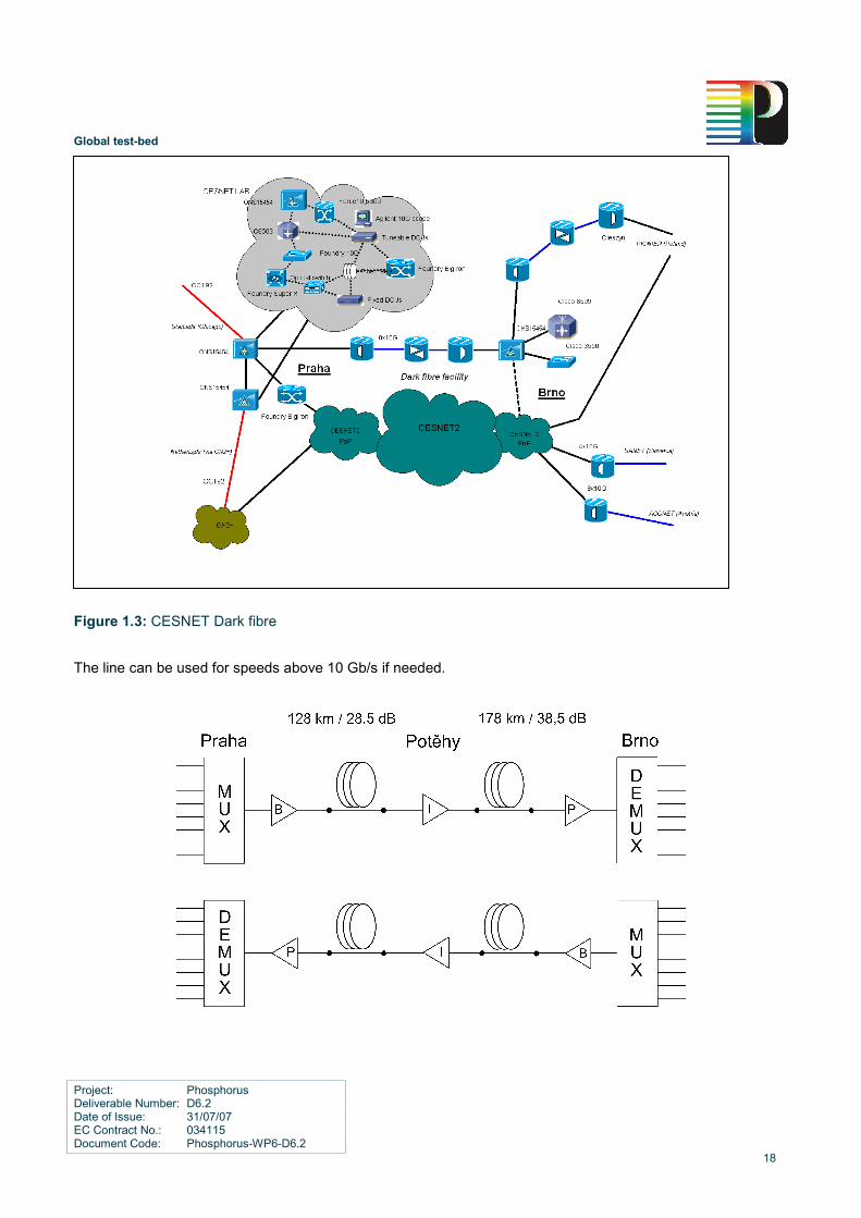
1.2.3 Experimental dark fibre line Praha - Brno (CESNET)
1.2.3.1 Line
The line is composed of 298,5 km of G.652/G.655+/G.655- fibres having 67 dB of attenuation and 440 ps/nm of
chromatic dispersion. There’s one inline amplifier and no compensators of chromatic dispersion.
1.2.3.2 Deployment
The line is the longest one in the testbed and was planned to be deployed as NIL with utilization of Raman
amplification. It all started as an experiment over 302 km/65 dB of mixture G.652/G.655+ on fibre reels because
we were trying to simulate the real line. Dispersion compensation fibres were used together with EDFAs and
Raman amplifiers. This worked quite well in our lab. The next step was to deploy all equipment on the real line.
We found that the combination of G.655+/G.655- is almost balanced and therefore no compensation was
needed (440 ps/nm is well within the margins of transceivers). The real attenuation 67 dB was too high (even
the attenuation coefficient is 0,225 dB/km which is really excellent) and even with powerful Raman amplifiers
the line experienced too bad BER. Therefore Raman amplifiers had to be displaced and one inline EDFA had to
be deployed. As a matter of fact, a NIL solution with Ramans was too sensitive to planned future upgrades to
more DWDM channels and the final solution with inline amplification was not that bad.
Perhaps one important result we have found is that G.652 fibres are a rather good choice when one need to
work with high power equipment (some EDFA boosters and all Raman equipment) because of a larger effective
area (i.e. a bigger core diameter). Therefore G.652 fibres are not so sensitive to nonlinear effects like self
phase modulation (SPM) and cross phase modulation (CPM) for DWDM systems. Both last miles in Praha and
Brno are G.652 fibres and not G.655 (we asked to extend the length of G.652 to approx. 25 km as last miles).
1.2.3.3 Advantages for project
The line connects two major cities Praha and Brno. Praha has connections to NetherLight (via Geant2+) and to
StarLight (a direct lambda), Brno has Nx10G connections to Slovakia and Austria, which can be used for the
project too. Another Nx10G line Brno – Cieszyn is being prepared – please see the following paragraphs.
Global test-bed
Project: Phosphorus Deliverable Number: D6.2 Date of Issue: 31/07/07 EC Contract No.: 034115 Document Code: Phosphorus-WP6-D6.2
18
Figure 1.3: CESNET Dark fibre
The line can be used for speeds above 10 Gb/s if needed.

Global test-bed
Project: Phosphorus Deliverable Number: D6.2 Date of Issue: 31/07/07 EC Contract No.: 034115 Document Code: Phosphorus-WP6-D6.2
19
1.2.4 Experimental dark fibre line Brno (CESNET) – Cieszyn (PIONIER)
1.2.4.1 Line
The line is composed of 264 km of G.652 fibre showing totally about 63 dB of attenuation and 4500 ps/nm of
chromatic dispersion.
1.2.4.2 Planned optical deployment
A deployment is planned as cost effective static DWDM system based on CLA devices allowing up to
8 avelengths with speeds up to 10 Gbps. A NIL (Nothing-In-Line) solution is possible but would need distributed
Raman amplification. To avoid high cost and high powers in fibres a solution with one inline amplification point
was proposed. All amplification points will use CLA boxes with remote monitoring and management. Chromatic
dispersion will be compensated using FBGs (Fibre-Bragg-Grating).
1.2.4.3 CLA amplifiers
The lack of optical equipment suitable for NREN’s needs in past years led CESNET to develop optical - building
kit composed from commercially available elements and modules. The result is low-profile and reliable rack
mountable device having a plenty of management interfaces. Reliability is increased by e.g. power supply
redundancy, important parameters monitoring, amplification and management part independency and usage of
non-moving parts (hard disc).
Real life usability was proven in CzechLight testbed and then within NREN CESNET2 network in past. In year
2006 a CBF triangle A-CZ-SK was finished enabling the interconnections of neighbouring NREN CESNET2,
SANET and ACOnet at the optical level (Layer-1). Two lines Brno – Bratislava (about 200 km, 45 dB
attenuation, G.652 fibre) and Brno – Vienna (224 km, 50 dB, G.652) are operated by CLA amplifiers. More
details can be found at http://www.ces.net/doc/press/2006/pr061106.html.
1.2.4.4 Advantages for project
Among the most important features belong a fact that device is operated by SW based on Linux and allowing
easy remote monitoring, management and possibility of future development. Parameters like optical powers,
currents, voltages, temperatures, fan speeds can be monitored.

Global test-bed
Project: Phosphorus Deliverable Number: D6.2 Date of Issue: 31/07/07 EC Contract No.: 034115 Document Code: Phosphorus-WP6-D6.2
20
Cross Border Dark Fibres Brno (CZ) – Cieszyn (PL), 263km, 8 x 10 Gb/s
1.2.5 Open dark fibre and photonic facility
CESNET has dark fibre facility and photonics lab, enabling building of testbeds for different projects and
purposes. This allows integration of L1/L2 elements and support of designing the Internet of the future at all
network levels (from dark fibre lighting to network applications in different research areas). Testbeds based on
lambda connections only (without full access to dark fibres and programming of lighting devices) are
considered useful but not sufficient for above task. CESNET has experience in deployment of dark fibres since
1999 and in deployment of open source photonics products since 2002.
The facility enables fundamental shift from current networking technologies that are optimized for legacy
Internet, and do not offer the software programmability and flexibility required by the research community.
Modular optical components (photonics industry products) readily available in the market and based on
standards allow building of fully programmable optical network platforms. This extends well-known open
approach from software development to hardware and optical devices development and management.
CESNET has 4 cross-border fibres (CBF) to neighbor NRENs now. We suppose our testbeds will be connected
by CBF to other dark fibre testbeds (dark fibre islands) in different projects, if feasible from budgetary view
(supposing fibres are available, cost for multispan lighting is now about 200 kEUR/1000 km for 8 lambdas using
open systems). Interconnection of two or more dark fibre testbeds by lambdas will be seen as possible
temporary solution. The main purpose of interconnection is to achieve synergy effect by joint research. Dark
fibre testbeds will be open for partners for collaboration on the place or by remote access, if technically feasible.
For example, CzechLight Amplifiers (programmable optical devices with remote control) are now manufactured
by two independent companies under license of CESNET and CESNET developed prototypes of CzechLight
tuneable CD Compensator and CzechLight semiconductor optical switch. This means development of above or

Global test-bed
Project: Phosphorus Deliverable Number: D6.2 Date of Issue: 31/07/07 EC Contract No.: 034115 Document Code: Phosphorus-WP6-D6.2
21
similar devices will not be supported by Phosphorus project, but CESNET will support Phosphorus project by
possibility to use such devices in the testbed.
For Phosphorus purposes, the facility will allow testing and integration of above devices as well as L1 agnostic
switches, impairment monitoring and lightpaths switching and restoration, fibre lighting by new advanced
products of photonics industry, testing of reconfigurable optical transport systems, testing of inter-operability in
multi-vendor environment (including lighting products and alien waves), implementation of services by multiple
lambdas (for example 10x10G or 5x20G), etc.
This means CESNET testbed for Phosphorus project can be modified step by step as result of intra-
Phosphorus discussion about:
• what optical parameters of transmission are interesting for monitoring and optical resource
management,
• what improvements of programmable optical devices (amplifiers, compensators, semiconductor
switches) are recommendable

Global test-bed
Project: Phosphorus Deliverable Number: D6.2 Date of Issue: 31/07/07 EC Contract No.: 034115 Document Code: Phosphorus-WP6-D6.2
22
1.3 i2CAT testbed
The Phosphorus test-bed located at i2CAT is going to be used to test the interoperability between different
NRPSs and between UCLP and GMPLS. It is also going to be used to test TOPS application. The switching
layer will be composed by L2 switches and optical equipment from Nortel and Alcatel. Our test-bed will also
include some computational resources that can be connected to the Phosphorus test-bed data plane.
The i2CAT local test-bed data plane will be connected to other Phosphorus test-beds data planes using the
infrastructure of the Spanish NREN (RedIRIS) that is connected to Géant2. However the i2CAT connection to
GLIF facilities in Amsterdam will also be used to expand our Phosphorus test-bed.
1.3.1 GRID resources in local test-bed
Grid resources in the i2CAT local test-bed include the following hardware:
• 9 x Blade Dell PowerEDGE 1855, Pentium Xeon 2.8 Ghz, 512/1024 MB RAM, 73/140 GB HD and
Gigabit Ethernet interface.
• 5 x Pentium IV 2.8 GHz , 512 MB RAM, 120 GB HD with Gigabit Ethernet interface.
All grid nodes have a Debian Linux OS and Globus 4.0 installed.
1.3.2 Optical networking and physical layer resources in the local test-bed
At this moment it is not planned by i2CAT to use any optical switch like a Glimmerglass switch or from any
other vendor for its local test-bed. Electrical switching will be performed with Cisco equipment. Most of them are
Cisco Catalyst 3750 switches because of its policy, bandwidth adjustments and jumbo frames support. Note
that the Gigabit Ethernet switches will not be controlled by UCLP version 2.
All connections inside the local test-bed will use Gigabit Ethernet as the transmission technology. In some
cases Gigabit Ethernet links will be over a DWDM 200GHz spaced ring while others (short distance) will use
Gigabit Ethernet PHY over copper or fibre (850nm). In the same way, the connection to and between i2CAT
computing resources will use Gigabit Ethernet links. In order to share the computing resources with other
i2CAT projects we will use L2VPN technology in our IP core network.
The DWDM ring will be implemented using two Nortel OPTera Metro 5200 boxes. Each one has the capability
to transmit 2 Gigabit Ethernet plus 2 SDH channels up to 2,5 Gbps. The internal architecture of the Nortel
Metro OPTera 5200 will permit the possibility to create a Gigabit Ethernet connection and teardown it.
The possibility to connect one of the Gigabit Ethernet channels to the other one also exists, acting as
a loopback. This capability will be interesting in order to connect different partners acting only as a transit
network. The 2 SDH channels will not be used because i2CAT has not any client equipment supporting this

Global test-bed
Project: Phosphorus Deliverable Number: D6.2 Date of Issue: 31/07/07 EC Contract No.: 034115 Document Code: Phosphorus-WP6-D6.2
23
technology. The mentioned Nortel OPTera devices will be controlled by UCLP. The connections to other
partners can follow two options depending on its topological location (they can be connected through Géant2 or
not). The first one is across our NREN who is connected to the Géant2 network and the interface to that partner
will be a 1000Mbps CBR VLAN. The tags are not specified for now. The other way is using i2CAT connection to
GLIF infrastructure. In this case, the interface to the internal test-bed will be Gigabit Ethernet in 850nm or
1310nm (depending on our disponibility of SFP's). In this case, the technology used on the link to the GLIF
infrastructure will be Gigabit Ethernet over SDH. GFP will allow us to adjust the bandwidth from 155 Mbps to
1 Gbps.
1.3.3 Topology of connections inside the local test-bed
The following figure describes the i2CAT local test-bed:
No
rtel
OP
Ter
a 5
20
0(P
ho
sph
oru
s #2
)
ALC
AT
EL
185
0T
SS
-320
VLA
N i2
CA
T-S
UR
Fn
et
VLA
N i2
CA
T-C
RC
VL
AN
i2C
AT
-VIO
LA
SF
P L
X
ava
ilab
le
SF
P S
Xa
vaila
ble
GL
IF#
4(S
MF
)G
LIF
#3
(SM
F)
GL
IF#2
(MM
F)
Figure 1.4: i2CAT test-bed

Global test-bed
Project: Phosphorus Deliverable Number: D6.2 Date of Issue: 31/07/07 EC Contract No.: 034115 Document Code: Phosphorus-WP6-D6.2
24
The connection from i2CAT to PSNC is carried by local (Catalonia, CESCA) and national (Spain, RedIRIS)
NRENs to PSNC through Géant2 network using an end to end VLAN. For now is not planned to upgrade this to
an end to end transparent GE interface. But it is possible to plan a Q-in-Q scenario between partners using this
feature in the Phosphorus switch at i2CAT and the same schema on the other side. The incoming VLAN arrives
to the Phosphorus test-bed through one i2CAT's core network switch. The first network element is a Nortel
OPTera Metro 5200 (OCI 5 @ OPTera #1) able to transport to any other of the OPTera Metro's OCI in any
shelf.
The connections going through CATLight and GLIF networks are quite different because of the use of NG-SDH
as a transport technology. So it’s possible to establish different VLANs (using 802.1Q tagging) between
partners. LCAS is not enabled so dynamically change the capacity of each circuit is not possible. On the other
hand, VCAT is used to assign capacity to each cirtuit with a granularity of STS-3c. The network element in
charge of mapping the Ethernet VLAN to the SDH link to GLIF hub (NetherLight) is an Alcatel 1850TSS-320.
The connections using this scenario are i2CAT to CRC, SURFnet and VIOLA, being the last one not yet
configured and SURFnet being in progress too.
All the connections from the Alcatel enter the Phosphorus test-bed passing through the Cisco Catalyst 3750
switch of the local test-bed, which supports JumboFrames and allows the aggregation / segregation of VLANs
and manual assignation to the desired ports. The Alcatel is transparent to the incoming VLANs of the local
Phosphorus test-bed.
Two connections are enabled between the network part and the application part (switch to connect to server
farm) to maximize the end partners connected to it and maintain the possibility of connecting different partners
between them, acting as a pass-through network.
1.3.4 Control and provisioning plane in the local test-bed
As an NRPS developer i2CAT will deploy UCLP on its local test-bed. In particular we will use UCLP to control
the Nortel OPTera Metro platform. The server running UCLP will be located on i2CAT premises and will have
two GigabitEthernet interfaces. One will be connected to the Control Plane using a VPN created using software
and the other one will be connected to a port of a L2 switch with a dedicated VLAN for the management of the
optical equipment involved on this project. This way all the optical devices that will be controlled on the i2CAT
Phosphorus test-bed will have their management ports connected to ports on L2 switches with the
management VLAN configured on them.
We have mainly two options regarding the management protocol used to configure the equipment: SNMP and
TL1. We have decided to use the TL1 interface to set up connections.
In case we want to interconnect UCLP with other NRPSs (through the NSP) or GMPLS controlled domains, our
UCLP server will be able to communicate with them through the interface connected to internet using the VPN
software. Moreover, this interface will also allow a user located on a remote site to control the i2CAT using the
UCLP software running in the UCLP server.

Global test-bed
Project: Phosphorus Deliverable Number: D6.2 Date of Issue: 31/07/07 EC Contract No.: 034115 Document Code: Phosphorus-WP6-D6.2
25
1.3.5 Middleware and applications in the local test-bed
Our test clients will be composed by computing resources in the local test-bed that run a Linux operating
system and have a GT4 stack installed. During the first phase of the project we plan to have as an application
in our test-bed TOPS. In particular we will configure a cluster to act as a visualization end point using a tiled
display.
1.3.6 Interconnection with other local test-bed
i2CAT local test-bed will be connected to four different partners using two international connections.
Figure 1.5: i2CAT connections to other partners
Firstly, i2CAT local test-bed will connect to PSNC local test-bed through the Géant2 infrastructure using an end
to end VLAN. The link ends in a Nortel OPTera Metro 5200 dedicated to the project.
Secondly, i2CAT local test-bed will connect to VIOLA, SURFnet and PSNC local test-beds through a 10 Gbps
SDH link provided by GLIF and local NRENs. Each one of these connections uses 7xVC-4 containers, and is
converted to a different VLAN in the local test-bed using the Alcatel 1850TSS-320, that delivers the VLANs to
the test-bed switch.

Global test-bed
Project: Phosphorus Deliverable Number: D6.2 Date of Issue: 31/07/07 EC Contract No.: 034115 Document Code: Phosphorus-WP6-D6.2
26
1.3.7 Integration with other local test-beds
At control plane level, i2CAT test-bed will be connected with the other two types of NRPS: ARGON and DRAC.
All the NRPS-controlled domains previously registered with the Network Service Plane, will be able to
intercommunicate between them and create interdomain and intradomain connections through the
correspondent NRPS.
At the Grid Middleware layer, for TOPS application test, i2CAT test-bed will install and deploy Globus Toolkit
version 4.
At the application layer, integration with TOPS is required.
1.3.8 Operation in local test-bed
The i2CAT local test-bed will participate in the TOPS application test. The local UCLP NRPS will be able to
configure optical paths inside the local test-bed and will communicate with the other NRPSs to create the
connections required between the local test-bed and the other Phosphorus test-beds. Inside the local test-bed,
the NRPS will control 2 Nortel Optera Metro 5200.

Global test-bed
Project: Phosphorus Deliverable Number: D6.2 Date of Issue: 31/07/07 EC Contract No.: 034115 Document Code: Phosphorus-WP6-D6.2
27
1.4 SURFnet testbed
The local SURFnet test-bed is used for testing of DRAC in Workpackage 1. It will also be used eventually to
connect applications provided by local partners (SARA, UvA) to the actual middleware-controlled network. The
testbed currently contains three Nortel OME6500s and two servers running the DRAC controller.
The SURFnet testbed is connected with three ports to the SURFnet L2 phosphorous hub switch, making it
a possibility to connect directly to the three other partners in Workpackage 1, and when required to any other
partner wishing to make use of the SURFnet testbed. The connections across the testbed can currently be
controlled manually by the participants via the web interface at http://drac.surfnet.nl/. Additionally the web
services interface that is used to interface with the NSP-adapter is also available.
1.4.1 GRID resources in the local test-bed
The SURFnet network does not contain any grid resources. It is limited to a setup representing the transport
network that can be controlled by the applications requiring their own dedicated connections. For basic testing
a pingable host is connected as a client.
1.4.2 Switching and transmission resources in the local test-bed and their
connections
The core of the local test-bed is built from three SDH cross connects, which switch VC4 connections when
requested by DRAC. The SDH cross connects are Nortell 6500 MSPPs. The three nodes are connected via 10
Gbps links, building a triangle. Each of the nodes has several GE ports and can be able to switch each GE port
to any other GbE port using SDH connections. Three GE ports are connected to the Phosphorous hub switch
where transparent connections are created towards three other Workpackage 1 partners.
The connections inside the local test-bed are configurable via DRAC. All endpoints are currently GE ports,
however it is foreseen that a L1 connection will be tested as well. This connection is already physically
connected between the testbed and NetherLight. This will make it trivial to expand testing to include multiple
heterogeneous technologies.
The topology of the test-bed as well is shown in Figure 1.6.

Global test-bed
Project: Phosphorus Deliverable Number: D6.2 Date of Issue: 31/07/07 EC Contract No.: 034115 Document Code: Phosphorus-WP6-D6.2
28
Figure 1.6: Topology of the SURFnet local test-bed
1.4.3 Control and provisioning plane in the local test-bed
The transmission nodes are controlled by DRAC. DRAC is installed on a server that is publicly accessible via
http://drac.surfnet.nl/. This is also the interface for the secure web services. The signalling to create
connections across the testbed is therefore completely out-of-band. Internally the DRAC server talks directly to
the nodes via the secure SURFnet DCN. Connecting to DRAC will happen via an adapter that is purposely built
for Workpackage 1 integration into the NSP. The connection between the NSP and the adapter will be secured
with a VPN.
1.4.4 Middleware and applications in the local test-bed
The SURFnet network does not contain any application. It is a setup representing the transport network that
can be controlled by the applications requiring their own dedicated connections. Except for the DRAC controller
no additional middleware is planned to be required for the project.
1.4.5 Interconnections with other local test-beds
The SURFnet test-bed is directly connected to the SURFnet phospohorous hub switch with 3 physical links.
From the hub switch connections are created to i2CAT, CRC and Viola. All three connections have been tested
and are functional. These connections are created using multiple VLANs to simulate light paths on a single
physical link.
L2 hub Switch
i2CAT
Viola_1
PSNC
Test host
All connections are transparent GEs GE circuits can be set up on SURFnet Testbed
DRAC http://drac.surfnet.
SURFnet testbed – three OME6500
nodes
NSP, applications, users
UNI
E-NNI
E-NNI
E-NNI

Global test-bed
Project: Phosphorus Deliverable Number: D6.2 Date of Issue: 31/07/07 EC Contract No.: 034115 Document Code: Phosphorus-WP6-D6.2
29
1.4.6 Integration with other local test-beds
To ensure smooth interactions between the SURFnet local test-bed and other Phosphorus only control plane
integration is necessary. This activity is fully covered in Workpackage 1, and will eventually allow to
transparently control the testbed together with other testbeds. Proof-of-principle testing of the connection
capabilities have been done, and middleware integration is proceeding. The public server that was required to
allow other testbeds (or the NSP) to interact with the SURFnet local testbed has been installed and tested.

Global test-bed
Project: Phosphorus Deliverable Number: D6.2 Date of Issue: 31/07/07 EC Contract No.: 034115 Document Code: Phosphorus-WP6-D6.2
30
1.5 UvA testbed
The UvA testbed is dedicated to developments in Workpackage 1 and 4 and may be used by applications if
needed and fits in the schedule. The testbed consists of several smaller testbeds, which allows the
collaboration to experiment with various Authorization models in different control plane implementations. In
particular the following basic Authorisation models are implemented as a separate testbeds: a GMPLS (Dragon
based) Network Resource Provisioning System (NRPS), a Token Based Network using in-band signalling
(based on IXDP2850 network processor). The testbed also provides an example of the multidomain
heterogeneous infrastructure for investigating the use of the Network Description Language
(http://www.science.uva.nl/research/ sne/ndl) as a semantic model for topology information exchange between
the various UvA testbeds. The testbed includes several cluster computer setups that can be used to experiment
with applications using the various control plane implementations as Grid resources. UvA testbed relies on the
SURFnet testbed resources that in particular provide the DRAC testbed and uses the LightHouse experimental
facility run by UvA. A new testbed consisting of 3 clusters of control plane nodes and 802.1Q VLAN switches
will be integrated to allow interoperability testing with various GMPLS implementations deploying G2MPLS,
DRAGON, etc. Also, authorization interoperability with domains using NPRS’s such as DRAC, ARGON and
UCLP are intended to be supported.
1.5.1 GRID resources in the local testbed
We have three different cluster computer setups that can be connected to the testbed. Those are the Van Gogh
cluster, the Rembrandt cluster and DAS-3 connected via StarPlane (www.starplane.org)
Furthermore there are several individual computers that support service, control and data plane functions in the
testbed. Here are some pictures of the clusters:

Global test-bed
Project: Phosphorus Deliverable Number: D6.2 Date of Issue: 31/07/07 EC Contract No.: 034115 Document Code: Phosphorus-WP6-D6.2
31
Figure 1.7: The VanGogh / Rembrandt cluster nodes in Netherlight / Lighthouse
Figure 1.8: The DAS-3 Cluster Node at UvA Netherlight

Global test-bed
Project: Phosphorus Deliverable Number: D6.2 Date of Issue: 31/07/07 EC Contract No.: 034115 Document Code: Phosphorus-WP6-D6.2
32
1.5.2 Switching and transmission resources in the local testbed
Here we describe only the switching elements in our control plane test setups in our laboratory. Obviously the MEMS devices in the picture above are also included. The StarPlane network is described on http://www.starplane.org/ .
The first described CP-testbed is the GMPLS setup.
Figure 1.9: The GMPLS testbed setup
The second CP-testbed is the UCLP2 setup:
Figure 1.10: The UCLP Testbed based on NORTEL OME’s

Global test-bed
Project: Phosphorus Deliverable Number: D6.2 Date of Issue: 31/07/07 EC Contract No.: 034115 Document Code: Phosphorus-WP6-D6.2
33
The third testbed to note is the Token Based Network testbed: Token Based Switch is a low-level system for
traffic routing at high speeds (multi gigabits/sec) based on packet authentication. TBS helps high-performance
computing and grid applications that require high bandwidth links between grid nodes to bypass the regular
Internet for authorised packets by establishing shortcuts on network links with policy constraints. TBS is fast
and safe and uses the latest network processor generation (Intel IXP2850). The associated testbed architecture
is depicted in the next pictures. The first figure (1.11) shows an overview of the context where TBS-IP systems
will be plugged in. In this first case, we suppose to build an end-to-end connection composed of lightpaths
based only on IP packets. The second figure (1.12) shows another context where TBS-IP systems work
together with GMPLS testbed connected as a separate network domain. In other words, in this scheme we
suppose to have some GMPLS lightpaths within the end-to-end connection that uses normally IP packets.
iD, Key
IP_hdr, IPsec_AH, Data
IPsec pkt.
AAA
PDP
DRAM
TVS STS
AAA
PDP
DRAM
TVS STS
DRAM
TVS STS
User/Apps
ForCEG-IXP
TBS-IP (Domain 3)
TBS-IP (Domain 2)
ForCEG-IXP ForCEG-IXP
TBS-IP (Domain 1)
AAA
PDP
request
TB/STS
request
default default default
iD, Key
User/Apps
Requestor
TB/STS
Figure 1.11: The planned Token Based FORCES router setup.
iD, Key
IP_hdr, IPsec_AH, Data
IPsec pkt.
AAA
PDP
DRAM
TVS STS
AAA
PDP
PEP
TVS STS
PEP
TVS STS
User/Apps
DRAGON VLSR
TBS-GMPLS (Domain 3)
TBS-IP (Domain 2)
ForCEG-IXP DRAGON-CSA
ForCEG-IXP
TBS-IP (Domain 1)
AAA
PDP
request
TB/STS
request
default default
iD, Key
RSVP-TE
OSPF
AAA
PDP
PEP
TVS STS
ForCEG-IXP DRAGON-CSA
default
TBS-IP (Domain 4)
RSVP-TE
OSPF
User/Apps
Requestor
TB/STS
Figure 1.12: A future multi-domain Token Based test setup using GMPLS.

Global test-bed
Project: Phosphorus Deliverable Number: D6.2 Date of Issue: 31/07/07 EC Contract No.: 034115 Document Code: Phosphorus-WP6-D6.2
34
1.5.3 Multi domain AAA testbed.
This testbed is being constructed and should be operational end of Q3 2007. It is intended to support various
GMPLS implementations such as DRAGON and, when available from Workpackage 2, G2MPLS. Also NPRS
based domains can be implemented in the testbed. Each domain in shown picture has 3 CPU nodes, 2 nodes
are intended to act as a control plane node, driving 802.1Q VLAN switches (or other types if necessary and
made available to this testbed) and accepting and forwarding signalling messages via an east-west interface
and communicating operation and control messages via a North/South bound interface, which are generated by
the 3rd node. The 3rd node will act as a service plane / AAA node that provisions the control plane with service
and AAA information. The testbed will be made accessible to both partners from the Phosphorus project and
organizations that want to collaborate in the area of AAA, such as Internet2.
Figure 1.13: Multi-domain Generic AAA Testbed at UvA Lighthouse
1.5.4 Topology of connections inside the local testbed
The different parts of the testbeds are connected with fibre supporting 1 and 10 Gbps, passing through the
MEMS devices from Calient and GlimmerGlass. This will enable dynamic reconfiguration of the inter-
connectivity.

Global test-bed
Project: Phosphorus Deliverable Number: D6.2 Date of Issue: 31/07/07 EC Contract No.: 034115 Document Code: Phosphorus-WP6-D6.2
35
1.5.5 Control and provisioning plane in the local testbed
Part of the GMPLS testbed will initially be controlled by the DRAGON project implementation. This
implementation has been augmented with our own AAA modules to allow Authorization. This functionality is
intended to be incorporated into the Phosphorus GMPLS/G2MPLS implementations when they become
available. Other parts of our testbed will be controlled by NPRS style control/service plane implementations
using for example webservices based interfacing.
1.5.6 Middleware and applications in the local testbed
The middleware deployed in this testbed is based on the current releases of UCPL2 and Dragon GMPLS
software augmented with our components to enable the topology information framework as developed in
Workpackage 1 and Authorization modules as developed in Workpackage 4.
1.5.7 Interconnections with other local testbeds
Interconnection with other local testbeds will be done via the MEMS devices and our layer 2 switches as
depicted in the first picture in this section. Connectivity to other testbeds is handled via NetherLight.

Global test-bed
Project: Phosphorus Deliverable Number: D6.2 Date of Issue: 31/07/07 EC Contract No.: 034115 Document Code: Phosphorus-WP6-D6.2
36
1.6 UESSEX testbed
UEssex local test-bed comprises a hybrid optical network testbed involving wavelength switching, sub-
wavelength switching (OBS) and GigEthernet/VLAN switching. Additionally, the test-bed includes a Grid
computing cluster connected to the hybrid optical testbed. The UEssex local testbed will be connected to the
Phosphorus global testbed through UKLight dark fibre, JANETLigtht Path and GN2.
The UEssex local testbed is going to participate in INCA, DSSS, KoDaVis and WISDOM application tests as
defined by Workpackage 3.
1.6.1 UEssex Grid computing resources
UEssex Grid computing resources comprises:
• One SGI Altix 450 Mide-Range and Multi-CPU computer server. It comprises 20 Dual Core Intel Itanium
2 Processors and 20GB RAM.
• One The SGI InfiniteStorage 220 Storage solutions with 4TB capacity
• Three Dell servers with Dual core Intel Xeon Processor at (2.40GHz and 1.86GHZ) and Gigabit
Ethernet interfaces
• Anritsu Network/data analyzer/generator which can emulate traffic and analyse data traffic in the
testbed at 1GbEtherent and 10GbEtherent.
UEssex is in the process of purchasing the SGI Altix 450 supercomputer and the SGI InfiniteStorage 220
storage. They are expected to be ready and operational for the test-bed by end of September 2007. Three Dell
servers and the Antirust network/data analyzer/generator (MD1230) have already been installed in the test-bed
and they are ready to participate in the initial application test.
UEssex will participate into the first phase of the Phosphorus global test-bed with three servers (as test-only
clients) and the Anritsu network monitoring device. The full Gird resources including supercomputer and
storage will be ready for participation in the second phase of the project.
1.6.2 Optical networking and physical layer resources in the local testbed
The optical networking testbed in the UEssex comprises of three main parts: the optical core wavelength
switched testbed, the sub-wavelength switched (optical burst switching) testbed and the high-speed all optical
signal processing testbed.
A. Optical wavelength switched testbed: It comprises one Calient DiamondWave FiberConnect switch. This
switch has been partitioned into four virtual independent switches. These switches have been connected in

Global test-bed
Project: Phosphorus Deliverable Number: D6.2 Date of Issue: 31/07/07 EC Contract No.: 034115 Document Code: Phosphorus-WP6-D6.2
37
a semi-mesh topology and they interconnect different parts of the local testbed as shown in Figure 1.14. The
optical wavelength switched testbed has the capability for DWDM transmission at Bit rates: 1 Gbps, 10 Gbps,
40 Gbps, and 160 Gbps.
The Calient DiamondWave FiberConnect Switch has been installed and tested in the test-bed. The wavelength
switched test-bed physical layer is ready for participation in the Phosphorus test-bed activities. It provides
connectivity between Phosphorus global testbed and UEssex local optical and Grid testbed facilities as shown
in Figure 1.14.
B. Optical sub-wavelength switching testbed: it is an optical burst switching testbed with capability of data
burst transmission at 2.5 Gbps. The testbed has been developed in UEssex and comprises two edge routers
and one core router. Each edge router can accept Gigabit Ethernet traffic and is able to map them into optical
burst according to the application requirements. The core OBS router is an active two section hybrid optical
switch. The active part of the router comprises a high-speed network processing engine which is able to
process data carried within OBS control header and perform advanced application-aware routing functionalities.
The optical switching part of the core OBS router comprises of a high-speed (ns regime) SOA based switch for
routing of small data bursts and a slow (20ms) 2D MEM-based switch for routing of large data bursts.
The optical sub-wavelength switched testbed is operational and will participate in Phosphorus testbed if it is
necessary and appropriate.
C. High-speed all optical signal processing testbed: this is a high-speed optical transmission testbed with
capability to support 160 Gbps transmission rate. With this testbed, it is possible to emulate different types of
transmission impairments such as loss and dispersion. It also has multi wavelengths 2R & 3R regeneration
facilities to compensate transmission impairments. Furthermore it supports all optical signal processing and
OTDM functionalities such as: all optical clock recovery, all optical data recovery and all and all optical time slot
interchanging. This part of testbed is operational and ready to participate in the Phosphorus global test-bed. It
can emulate different types of transmission impairments such as loss, dispersion and transmission links with
different lengths and qualities for the Phosphorus testbed. This will allow the Phosphorus control plane to
incorporate and consider constrain based routing with physical layer constrains as described in technical annex.

Global test-bed
Project: Phosphorus Deliverable Number: D6.2 Date of Issue: 31/07/07 EC Contract No.: 034115 Document Code: Phosphorus-WP6-D6.2
38
1.6.3 Local testbed connectivity
Figure 1.14: The UEssex topology of the local testbed and the testbed resources
Figure 1.14 shows the UEssex hybrid optical network and Grid testbed topology and connectivity. The local
testbed comprises two VLAN Gigabit Ethernet switches with 10GE and 1GE switching capability. The VLAN
switches are under purchasing process and they are expected to be deployed in the test-bed by end of August
2007.
One VLAN switch (VG2) connects the local Grid testbed to the optical core wavelength switched testbed. The
local Grid resources use Gigabit Ethernet for communication and their traffic is aggregated by the VLAN Gigabit
Ethernet switch for transmission over optical network.
The second VLAN switch (VG1) interconnects the Phosphorus global testbed to the optical core of the local
test-bed (wavelength switched testbed). It segregates/aggregates VLAN tagged traffic from/to different local
testbeds and interconnect them individually to the core of the UEssex local testbed. Deployment of the VG1
switch in the testbed allows segregation of VLAN tagged traffic from different sources into individual optical
links for switching through different part of the local testbed

Global test-bed
Project: Phosphorus Deliverable Number: D6.2 Date of Issue: 31/07/07 EC Contract No.: 034115 Document Code: Phosphorus-WP6-D6.2
39
The optical core wavelength switched testbed comprises one 96X96 Calient DiamondWave FiberConnect
switch. This switch has been partitioned into 4 virtual independent 24X24 switches (VS1,VS2,VS3,VS4). These
switches are connected in a semi-mesh topology as shown in Figure 1.14. They are connected together with
two main fibres (one for each direction) and two protection fibres. These switches interconnect the Grid testbed,
the optical sub-wavelength switched testbed and the high-speed all optical testbed to the Phosphorus global
testbed.
1.6.4 Control and provisioning plane in the local testbed
The UEssex local test-bed control plane comprises a network of six node controllers. They are Dell servers with
Dual core Intel Xeon Processor and each of them control one of the VG1,VG2,VS1,VS2, VS4 switches. The
control plane network has been installed and tested. It is operational and ready to deploy control and
provisioning plane of the Phosphorus global test-bed.
UEssex will deploy GMPLS control plane (Workpackage 2 deliverable) and UCLP NRPS in the first phase of
the project and also G2MPLS control plane (Workpackage 2 deliverable) in the second phase. The GMPLS/
G2MPLS control plane and the UCLP NRPS will control the optical switches (i.e. VS1,VS2,VS3 and VS4) at the
core. The node controllers use TL1 based interfaces to communicate with the switches.
The control plane network will deploy software based VPN to communicate with control plane in other local
test-beds. This solution will be based on a dedicated control plane node (PC) running VPN software which
allows using a common flat control plane network and also covers different sites. UEssex is currently liaising
with other partners in Workpackage 6 to setup the inter domain connectivity for the control plane. The inter
domain control plane connectivity is expected to be operational by end of August.
The PHOSPHORUS testbed doesn’t require for UEssex local testbed to have NRPS provisioning plane.
However UEssex is currently working with I2Cat (Workpackage 1 partner) to deploy UCLP in the local test-bed.
It is planned to deploy UCLP for controlling the VS1,VS2,VS3 and VS4 optical switches. This allows the
UEssex local test-bed to participate in the Phosphorus global testbed activities before delivery of GMPLS and
G2MPLS control plane from Workpackage 2. The UCLP is expected to be fully deployed in the UEssex local
test-bed by end of August.
1.6.5 Middleware and applications in the local testbed
All the test clients, the servers, the supercomputing and the storage resources in the local testbed are based on
Linux operating system. One server is planned to run Globus toolkit middle ware and it is allocated for DDSS
application and INCA application. Two other servers are planned to run UNICORE middle ware and they are
allocated for WISDOM and KoDaVis applications. All the servers are operational and ready to participate in the
test-bed activity.
UEssex is currently liaising with Workpackage3 partners to decide about appropriate applications and
middleware for the SGI Altix 450 supercomputer and the SGI InfiniteStorage 220 storage. The test-bed

Global test-bed
Project: Phosphorus Deliverable Number: D6.2 Date of Issue: 31/07/07 EC Contract No.: 034115 Document Code: Phosphorus-WP6-D6.2
40
activities with these computing and storage resources will be planned by end September when they ready and
operational.

Global test-bed
Project: Phosphorus Deliverable Number: D6.2 Date of Issue: 31/07/07 EC Contract No.: 034115 Document Code: Phosphorus-WP6-D6.2
41
1.7 VIOLA testbed
The local VIOLA test-bed is used for TOPS, DDSS, KoDaVis, and WISDOM applications tests, as defined by
Workpackage 3. The VIOLA test-bed contains switching, computing, visualization, and storage resources. The
switching layer is built from SDH cross connects and Gigabit Ethernet switches, computing resources include a
Cray X-D1 Opteron cluster and an Intel Xeon cluster. The main visualization resource is the i-CONE™ display
system. It consists of four Barco 909 projectors and provides a resolution of up to 2000x1460 pixels at 96 Hz.
The pixels are send over the network to a PC cluster, where each PC is attached to a projector. A STK tape
library serves as the main storage resource.
The VIOLA local test-bed will be controlled by the NRPS ARGON with GMPLS interface. The GMPLS control
plane provides automatic provisioning of optical paths based on SDH connections within the VIOLA test-bed
and between different Phosphorus test-beds.
1.7.1 GRID resources in the local test-bed
The main compute resources in the VIOLA test-bed are a Cray X-D1 system at FZJ (14 dual Opteron compute
nodes, each of them attached to the test-bed with a 1 GbE adapter) and an Intel Xeon cluster named PACK at
FhG-SCAI (17 dual Xeon compute nodes, each of them attached to the test-bed with a 1 GbE adapter). These
clusters will provide the compute capacity for the WISDOM and KoDaVis applications. They will also serve as
client nodes for the DDSS application.
AT FZJ, access to a TSM server with an STK tape library has been granted for the DDSS application
(backup/archive). The TSM client to be used by DDSS is installed on the Cray X-D1.
At FhG-IAIS we use the i-CONE™ display system for TOPS application. The i-CONE™ projects virtual
environments on a curved, 240 degree wide-angle screen. The screen is slightly tilted backwards to improve
visual and acoustic qualities. This technology eliminates the edges and corners of a CAVE™ – the cubic virtual
theatre widely used today. The i-CONE™ is driven in active stereo mode by a sgi Onyx or a PC Cluster (HP
xw8200, Quadro FX3000G) with a total resolution of up to 6200x1460 pixels. The i-CONE™ consists of four
channels with a resolution of 1440x1320 pixel or 1600x1460 pixel at 94 Hz per BARCO 909 projector. For the
initial test a single HP-workstation is used with one projector. This PC is connected with its Gigabit network
card to the VIOLA test-bed. As ist was not possible to put the existing PC Cluster outside the FhG-IAIS firewall
or to allow access from outside, the 4 Cluster PCs have been equipped with internal disks and been put into
a separate network which is available at SARA and FhG-IAIS. The PCs are connected to a Gigabit switch with
a Gigabit uplink to this network. Switching between internal network and testing network has to be done by
hand. Tests are in preparation.

Global test-bed
Project: Phosphorus Deliverable Number: D6.2 Date of Issue: 31/07/07 EC Contract No.: 034115 Document Code: Phosphorus-WP6-D6.2
42
1.7.2 Switching and transmission resources in the local test-bed and their
connections
The connections inside the local test-bed as well as all links to the other Phosphorus local test-beds use
Gigabit Ethernet as the transmission technology. This way the local test-bed uses the same transmission
technologies as most modern GRIDs. Gigabit Ethernet transmissions are switched in the test-bed in two layers
– on layer one by SDH cross connects and on layer two by Gigabit Ethernet switches using MPLS.
The core of the local test-bed is built from three SDH cross connects, which switch SDH connections by using
GMPLS. The SDH cross connects are Alcatel 1678 MCC systems.The cross connects are connected via 10
Gbps SDH links, building a triangle. Each of the SDH cross connects has at least 12 Gigabit Ethernet ports and
will be able to switch each GbE port to any other GbE port using SDH connections. The Alcatel cross connects
can be connected to OIF UNI 2.0 clients, which can be used for creating user initiated end-to-end connections.
Three Proxy UNI 2.0 clients from Alcatel are available within the test-bed.
The SDH cross connects are accompanied by three Riverstone 15008 Gigabit Ethernet switches between
which services based on MPLS tunnels can be defined. The Ethernet switches build the MPLS domain and add
an additional layer to the heterogeneous Phosphorus network. The connections between the Ethernet switches
themselves are 10 GbE links. Both SDH cross connects and Gigabit Ethernet switches will be controlled by the
NRPS ARGON or the Thin NRPS.
The Riverstone Gigabit Ethernet switches aggregate traffic from GRID resources which are connected to them.
The Alcatel 7750 Ethernet switches are used for connecting the VIOLA test-bed to the other PHOSPHORUS
test-beds (see chapter “Interconnections with other local test-beds”).
All Gigabit Ethernet Switches, SDH cross connects and Proxy UNI systems are connected to a common control
network (DCN network). This network is used for local management and configuration of the network devices.
The topology of the test-bed as well as all the test-bed resources is shown in Figure 1.15.

Global test-bed
Project: Phosphorus Deliverable Number: D6.2 Date of Issue: 31/07/07 EC Contract No.: 034115 Document Code: Phosphorus-WP6-D6.2
43
Jülic
h
Bonn
Jülic
h
Bonn
Sankt Augustin
San
kt Aug
ustin
Figure 1.15: Topology of the VIOLA local test-bed
1.7.3 Control and provisioning plane in the local test-bed
The SDH cross connects are controlled by GMPLS (in the first phase of the project) and G2MPLS (in the
second stage). For GMPLS these switches have a built-in controller. For G²MPLS they will have an external
controller made of a personal computer running a G2MPLS implementation. The GMPLS/G²MPLS controllers
and the UNI proxies are connected to a common Ethernet network for exchanging control plane traffic (out-of-
band signalling). The lat structure of the network allows communication between each pair of controllers. The
control plane network also interconnects GRID resources (computing nodes) with the controllers in order to
allow the exchange of control information between the GRID resources and the control plane of the network.
The control plane network has been implemented as a layer 2 segment to which all the controllers are
connected by Fast or Gigabit Ethernet links. The publicly available free software TINC will be used for

Global test-bed
Project: Phosphorus Deliverable Number: D6.2 Date of Issue: 31/07/07 EC Contract No.: 034115 Document Code: Phosphorus-WP6-D6.2
44
separating the control plane at different locations. This software also allows to use a common flat control plane
network, which covers different sites. Such a common network will allow capturing all control plane packets of
the whole test-bed at each side.
1.7.4 Middleware and applications in the local test-bed
The normal VIOLA middleware stack is installed on the X-D1 and PACK clusters. In addition to UNICORE, the
new Web-Service based UNIORE 6.0 has been installed on the Cray X-D1. Further components are an RMS
with advance reservation capabilities (PBS Pro on the X-D1, and EASY on PACK). Access to network
reservation services (ARGON) is provided via the MetaScheduling Service (MSS) located at SCAI. Distributed
MPI applications are supported by the MetaMPICH library and a specific MetaMPICH UNICORE client-plugin.
This middleware is required by the WISDOM and KoDaVis applications.
The Globus Toolkit 4.0.3 has been installed on the X-D1 and PACK for use by the GridFTP part of the DDSS
application (GridFTP).
A TSM (IBM Tivoli Storage manager) client is installed on the X-D1 for use by the backup/archive part of the
DDSS application.
The firewall systems have been configured to allow the middleware and distributed applications to
communicate as necessary with the other test-beds. This involved opening ports and port ranges for girdFTP,
UNICORE and applicationspecific ports for KoDaVis.
1.7.5 Interconnections with other local test-beds
The VIOLA local test-bed will have direct connections to Phosphorus local test-beds at SURFnet (3 physical
links and PSNC (1 link). One of the links to SURFnet has allready been established. The other links will be
provided until the end of September 2007. Via these test-beds other Phosphorus test-beds like I2CAT and CRC
can be reached. Multiple VLANs are used for simulating light paths on a single physical link. The links are
terminated in one of the Alcatel 7750 Gigabit Ethernet switches in order to de/multiplex the VLANs. The Alcatel
7750 switches are connected to the Alcatel SDH cross connects. These cross connects can switch the
connections from the other Phosphorus test-beds to local applications or to connections to other Phosphorus
test-beds.
1.7.6 Integration with other local test-beds
To ensure smooth interactions between the VIOLA local test-bed and other Phosphorus local test-beds
a precise integration is necessary. The integration covers three layers: control plane to ensure provisioning of
lightpaths between local test-beds (described in section 1.7.3), GRID middleware to allow for distributed

Global test-bed
Project: Phosphorus Deliverable Number: D6.2 Date of Issue: 31/07/07 EC Contract No.: 034115 Document Code: Phosphorus-WP6-D6.2
45
computing and use of distributed storage and applications to have the same application using resources in
different local test-beds.
The first version of the test-bed did not require a full integration of all components in order to enable the first
application tests. The following integration work has been performed:
• For UNICORE:
○ Installation of a UNICORE 5 and 6 servers in the VIOLA test-bed and of the respective UNICORE
clients in the other test-beds.
• For Globus Toolkit:
○ installation of version 4 of the Globus Toolkit at all
• For both Grid middlewares:
○ agreements with PSNC about Certification Authorities (CAs), exchange of certificates and mapping
of the distinguished names of certificates to local user accounts. Using EUGridPMA acknowledged
CAs has been the natural choice.
For the next version of the test-bed integration the following tasks have to be perfomed:
• For UNICORE:
○ Installation of UNICORE servers at the other test-beds and configuration of the servers to form
a common UNICORE grid.
On the application layer the following tasks have been performed for the integration with other local test-beds:
• DDSS GridFTP: configuration of GridFTP servers and clients at FZJ and FhG-SCAI.
• KoDaVis: configuration of the application data-server and test-only clients
• WISDOM: configuration of the application workflows. Local installation and tests of Docking tools
AutoDock and FlexX with BioSolveit 200Testdata set.
• TOPS: configuration of the visualization client. The connection of the video signal of the visualisation
client (PC Cluster of 4 PCs) to the i-CONE™ display is done by local switching procedures, the
projectors have to be switched on by hand. While the TOPS application is running the researcher at the
display site will view the pictures. Control of the application at the viewing side will be realized by using
a Logitech gamepad.
1.7.7 Operations in the local test-bed
All of the four applications defined in Workpackage 3 will access the VIOLA test-bed: WISDOM, KoDaVis,
TOPS, and DDSS (both GridFTP and TSM). These applications will use the Phosphorus services mainly
through the Grid middleware. This middleware is provided by Workpackage 3 and will access these services
either directly (e.g. the compute resources via UNICORE, the MSS and the local RMS) or through the

Global test-bed
Project: Phosphorus Deliverable Number: D6.2 Date of Issue: 31/07/07 EC Contract No.: 034115 Document Code: Phosphorus-WP6-D6.2
46
interfaces to Workpackage 1. As planned for the first phase, the MSS uses the ARGON system to access the
network services provided by the Phosphorus test-bed.
The distribution of the applications over the test-bed resources is shown in Table 1.1. The use cases which are
being deployed and tested in this local test-bed have been described by Workpackage 3 in the Deliverable
D3.1 “Use-cases, requirements and design of changes and extensions of the applications and middleware”.
More details can be found in that document. The table shows the current status of deployment of the
middleware and applications on the hardware resources in the VIOLA test-bed:

Global test-bed
Project: Phosphorus Deliverable Number: D6.2 Date of Issue: 31/07/07 EC Contract No.: 034115 Document Code: Phosphorus-WP6-D6.2
47
Resource WISDOM KoDaVis TOPS DDSS GridFTP DDSS B/A
Hardware resources
Cray X-D1 yes Initial version of server installed
gridFTP installed
TSM client installed
PACK Cluster yes yes yes
Visualization system (Display, PC graphics cluster
initial version installed, tests in preparation
STK tape library yes
Grid middleware
Globus Toolkit middleware
GT 4.0.3 installed
Unicore middleware UNICORE 5
installed UNICORE 5/6
installed
Other software
FlexX/Autodock FLEXlm, Oracle
• FlexX/AutoDock with test data set available
• FlexX floating licenses via dedicated port access to Flexlm server available
• Oracle actually not used
C/C++ compiler, MPI available available available
Other standard Linux packages
available
TSM available

Global test-bed
Project: Phosphorus Deliverable Number: D6.2 Date of Issue: 31/07/07 EC Contract No.: 034115 Document Code: Phosphorus-WP6-D6.2
48
Table 1.1: Application distribution over VIOLA local test-bed
Forschungszentrum Jülich: Cray X-D1
# Nodes 14 x 2-CPU for VIOLA and Phosphorus CPU Opteron, 2.2 GHz Memory per node 4 GB per Node (2 CPU) Home-Data 1.1 TB (global via NFS) Temp-Data 8 GB per node local (/tmp)
Fraunhofer Institute SCAI: PACK Cluster
# Nodes 17 x 2-CPU SMP + Login/Service-nodes (2 x SMP) +File/server-nodes(2 x SMP)
CPU 3,0 Ghz
Memory / node 2 GB ECC-RAM
Home-Data 320 GB
Temp-Data 80 GB
# Nodes 6
CPU 2 x Ultrasparc-IIIi 1,1 Ghz SUN Fire V240
Memory per node 2 GB RAM
Temp-Data 35 GB per node local (/space)

Global test-bed
Project: Phosphorus Deliverable Number: D6.2 Date of Issue: 31/07/07 EC Contract No.: 034115 Document Code: Phosphorus-WP6-D6.2
49
1.8 MCNC testbed
The existing Enlightened Computing testbed is a national-footprint optical network that has been deployed to
facilitate the middleware and application goals set forth by the project, as well as to support investigations into
new network and control plane architectural models. The core of the testbed is built using Calient Networks
Diamond Wave optical cross-connect (OXC) switches interconnected by Ten Gigabit Ethernet (10 GbE) circuits
provided by Cisco Systems and NLR.
GMPLS is used as the control plane protocol to allow dynamic instantiation of end-to-end paths across the
testbed, in order to interconnect computing and storage resources as required by applications. Each of the four
original sites that host an OXC also provides 10 GbE-attached switches and/or end hosts as well as the
potential to extend connectivity to users and resources via local Regional Optical Networks (RONs). Individual
institutions within the team administer their local nodes and help with planning and day-to-day maintenance of
the complete cooperatively managed domain.
1.8.1 GRID resources in the local testbed
Below is a figure of the Enlightened Resource testbed, to include compute resources off of each OXC. Access
to those resources can be discussed with the individual owners of the compute resources.
Figure 1.16: Topology of the Enlightened Resource testbed

Global test-bed
Project: Phosphorus Deliverable Number: D6.2 Date of Issue: 31/07/07 EC Contract No.: 034115 Document Code: Phosphorus-WP6-D6.2
50
1.8.2 Switching and transmission resources in the Enlightened testbed
All internal connections within the local testbed are realized with 10 Gigabit Ethernet circuits from National
Lambda Rail (NLR). Two circuit types are currently deployed: layer 1 circuits (NLR WaveNet service) and layer
2 circuits (NLR FrameNet service). The layer 1 handoff to the Enlightened testbed is directly from the NLR
DWDM equipment at each site. The layer 2 handoff is from NLR Ethernet switches at each site.
The core of the Enlightened testbed is built with optical cross-connect switches (OXC), interconnected by the
10 Gigabit Ethernet circuits described above. There are currently four OXCs deployed in the following locations
by Enlightened partners: Chicago, Illinois (Starlight), Los Angeles, California (Ulralight), Baton Rouge,
Louisiana (Louisiana Optical Network Initiative - LONI) and Raleigh, North Carolina (MCNC).
Since all direct connections to the OXCs are using 10 Gigabit Ethernet interfaces, the switching granularity of
the testbed is 10 Gigabit Ethernet. At the Starlight location, there is an Ethernet switch managed by LONI that
can be used to aggregate 10 Gigabit Ethernet circuits as needed.
In most cases, Ethernet switches are attached to tributary ports on the OXCs forming the edge of the testbed.
Computing and storage resources are then connected to the edge switch via Gigabit Ethernet of 10 Gigabit
Ethernet connections. In some cases, computing and storage resources are attached directly to tributary ports
on the OXC.
Currently all Ethernet ports that connect directly to the OXC are configured for untagged framing. This allows
for any to any connectivity between tributary ports, since trunk configuration don’t have to be matched. It also
eliminates the need to negotiate VLAN tag assignments between sites. The limitation of this method is that
trunks between sites are not supported.
End-to-end provisioning between sites is accomplished via a GMPLS control plane initiated from the Grid
middleware. The GMPLS control plane only establishes lightpaths across the Calient optical switches.
1.8.3 Topology of connections inside the Enlightened testbed
The current topology of the testbed is a hub and spoke, with the hub in Chicago at Starlight. One circuit
connects each site to the hub OXC.
The network team is currently working on extending the core topology of the testbed through a close
collaboration with NLR. A new OXC owned by NLR is being deployed in Kansas City, along with additional
circuits between key sites. The OXC and circuits will be full integrated into the GMPLS-controlled domain and
managed cooperatively with the other OXCs as an equal partner. Figure 1.17 illustrates the new extended
topology.
NLR is intending to use the combined testbed to pilot a resilient wave service that it would like to deploy as an
alternative to its' existing unprotected wave service. Combining the testbeds in this way allows both projects to

Global test-bed
Project: Phosphorus Deliverable Number: D6.2 Date of Issue: 31/07/07 EC Contract No.: 034115 Document Code: Phosphorus-WP6-D6.2
51
benefit from additional capacity and complexity of the combined facility. For example, the Enlightened team can
design new features in the middleware that allow the use of alternate paths to a single destination, as a means
of providing path recovery from that layer. Additionally, the team could investigate how the middleware should
react to a network layer recovery scenario, much like the resiliency function that NLR is planning to investigate.
Figure 1.17: Topology of the Enlightened testbed
1.8.4 Control and provisioning plane in the Enlightened testbed
The optical switches in the local testbed use GMPLS for the control plane. The Ethernet switches at the
network edge are currently configured statically. Using PC-based GMPLS controllers (Dragon’s VLSRs) to
instantiate dynamic VLANs on the Ethernet switches has been discussed, but there are no firm plans for
implementation at this time.
The control plane transport between OXCs on the Enlightened testbed is currently provided by normal NREN
IP service paths. To better protect and observe the traffic on this vital connection, MCNC has proposed a two-
phase project to use an NLR-provided FrameNet (Layer 2) circuit to build the control plane transport. The first
phase entails connecting the OXCs together via the multi-point FrameNet connection, and has been approved
by the NLR Network Research Council. Phase one is being deployed as part of the testbed expansion
described above.

Global test-bed
Project: Phosphorus Deliverable Number: D6.2 Date of Issue: 31/07/07 EC Contract No.: 034115 Document Code: Phosphorus-WP6-D6.2
52
The second phase of the proposed project will add the capability to support multiple control plane projects (via
VLAN segmentation) and capture control plane traffic to aid in debugging and protocol development. The phase
2 proposal is currently in process, and MCNC is hopeful that sufficient funding to move forward will be found in
the next few months.
Middleware provisions end-to-end paths by attaching to the management interface of the OXCs and using TL-1.
Manual provisioning can also be accomplished via the Calient Web-based GUI. We currently manually
provision the Ethernet switches attached to the OXCs. We are now investigating dynamic layer two provisioning
via control plane or middleware.
Investigation into using G2MPLS on the Enlightened testbed is just beginning.
1.8.5 Middleware and applications in the Enlightened testbed
The Enlightened middleware is currently capable of instantiating a GMPLS request to setup dynamic lightpaths
across the OXCs and coordinate with requested compute resources via HARC middleware. This is based
currently on a static topology, however, work has begun on implementation of topology discovery via OSPF
information captured by the OXC control plane.
1.8.6 Interconnections with other Enlightened testbeds
Based on the footprint of the Enlightened testbed, a natural interconnection point with other local testbeds is the
Starlight facility in Chicago. Discussions about which trans-continental circuits might be used and details of the
interconnections have just begun.
Currently there is an interconnection at Starlight between the Enlightened testbed and the JGNII GMPLS
testbed in Japan, using a JGNII-owned 10 Gbps circuit that terminates in Tokyo. Both data plane and control
plane connections use that circuit, segmented in different VLANs. The data plane connection terminates on the
Enlightened OXC in Chicago with a 10 Gigabit Ethernet interface. The control interfaces of the OXCs are
connected via Fast Ethernet connections to a small JGNII switch at Starlight.
The control plane connection between domains uses GMPLS E-NNI. We have successfully demonstrated
interdomain provisioning across this interface.
A similar strategy for interconnection could be used with other Phosphorus local testbeds. Data plane
connections via 10 Gigabit Ethernet interfaces could be easily accommodated directly on the OXC. Gigabit
Ethernet interconnections could possibly be accommodated using the Ethernet aggregation switch mentioned
above. Fast Ethernet control plane interconnections could possibly be hosted on the Ethernet switch owned by
JGNII.

Global test-bed
Project: Phosphorus Deliverable Number: D6.2 Date of Issue: 31/07/07 EC Contract No.: 034115 Document Code: Phosphorus-WP6-D6.2
53
1.8.7 Integration with other local testbeds
To ensure smooth interactions between the Enlightened testbed and some of the Phosphorus local testbeds,
precise integration is necessary. The integration must cover three layers: a control plane to ensure provisioning
of lightpaths between local testbeds, the GRID middleware to allow for distributed computing, and use of
distributed storage and applications to have the same application using resources in different local testbeds.
The Enlightened testbed currently supports interdomain provisioning using GMPLS E-NNI, as stated above.
Thus, interoperability with OXCs on other local testbeds using GMPLS E-NNI will require some detail
coordination as a first step. Supporting G2MPLS directly on the Enlightened testbed is still under investigation.

Global test-bed
Project: Phosphorus Deliverable Number: D6.2 Date of Issue: 31/07/07 EC Contract No.: 034115 Document Code: Phosphorus-WP6-D6.2
54
1.9 CRC testbed
The CRC testbed comprises equipment located in the Broadband Applications and Demonstration Laboratory
(BADLABTM) and the Optical Networking Laboratory (ONL) facilities and extends across CANARIE, Canada’s
advanced network. The CANARIE network elements assigned to the Phosphorus project can be managed and
controlled via the UCLP NRPS.
The LightPaths (LPs) established across CANARIE terminate at the GÉANT2 POP in New York, the GLIF POP
in New York and the STARLIGHT POP in Chicago enabling connections to other Phosphorus partner testbeds.
There is also an LP from CRC to Nortel spanning the CANARIE Ottawa POP.

Global test-bed
Project: Phosphorus Deliverable Number: D6.2 Date of Issue: 31/07/07 EC Contract No.: 034115 Document Code: Phosphorus-WP6-D6.2
55
1.9.1 Networking, computing, storage and visualization resources in local
testbed
The Table 1.2 shows the equipment available at CRC for the present project.
Networking Computing & Storage Visualization
• Cisco Catalyst 6509
(24 GbE SFP, 16 GbE
GBIC, 10/100 Ethernet,
100 MJRT Ethernet
blades)
• Cisco Catalyst 3750
• Force10 S2410 (24 x
10 GbE XFP)
• Force10 S50V (48 GbE
10/100/1000 Ethernet ,
4 GbE SFP, two port
10GbE XFP module)
• 8 Channel CWDM
MUX/DEMUX
• Cisco 12008 router
(GbE, ATM)
• Nortel OPTera Metro
5200 (GbE, DWDM)
• 8 x 8 Photonic
Switches
• 16 Channel ROADM
• 16 Channel DWDM
MUX/DEMUX
• EDFAs
• VOAs
• OCPM
• BERT Tester
• OSA
• 2 x Pentium Duo Core
Processors @ 3.2
GHz, 1.0 GB RAM,
200GB HDD
• 3 x Pentium IV Dual
Xeon @ 2.8GHz, 2.5
GB RAM, 2 x 40 GB
HDD
• 3 x Penitum IV 3.8
GHz, 1 GB RAM, 160
GB HDD
• 3 x Pentium IV Duo
Core Processors @
2.0 GHz Laptops
• 3 x Pentium IV Dual
Xenon @ 1.7 GHz,
512 MB RAM, 1 or 2
40 – 120 GB HDD
• 9 x Pentium IV 3.2
GHz, 512 MB – 1 GB
RAM, 100 – 160 GB
HDD
• UltraGrid Uncompressed HD
(Xena HS and DVS Centaurus
capture cards)
• SAGE 2x2 Tiled Display (Sharp
PN-455 45” LCD Monitors)
• 2 x NEC 50MP1 10” Plasma
Monitors
• Pleora Technology,
Uncompressed SD
• Pleora Technology, DVB-ASI
• Pleora Technology, HDV
• NiCT/TEL Ruff HDV System
• NiCT DVTS System
• ISABEL (Clients (26),
flowservers, license servers (24
users)
• H.323 (Polycom VSX 7000 with
MCU (x3), Polycom Viewstation
FX, Polycom PVX (x10))
• VideoLAN (HDV, DV)
• Skype
• Sony HVR-Z1U HD camcorder
• Sony HDR-SR1 HD camcorder
• JVC JY-HD10U HD camcorder
• JVC GR-HD1U HD camcorder
• JVC HM-DH5U recorder (x2)
Table 1.2: Equipment available at CRC for the project.

Global test-bed
Project: Phosphorus Deliverable Number: D6.2 Date of Issue: 31/07/07 EC Contract No.: 034115 Document Code: Phosphorus-WP6-D6.2
56
1.9.2 Optical networking and physical layer resources in the local testbed
The BADLAB facility is connected to the CANARIE Ottawa POPs via an 8-channel CWDM infrastructure. The
core switch/router in the BADLAB is a Cisco Catalyst 6509. A Nortel OPTera Metro 5200 is also available as
part of the Optical Networking Laboratory (ONL) adjacent to the BADLAB and supports GbE interfaces which
can be connected to the Catalyst 6509 and/or PC’s.
GbE is the common interface used on the CANARIE network elements shown in Figure 1.18. The GbE ports
are mapped onto STS-24c circuits (or lesser depending on availability and the bandwidth required by the
applications). The networking equipment in the BADLAB has been upgraded to support 10 GbE with the
addition of two switches from Force10 Networks as depicted in Figure 1.19. A request has been issued to
CANARIE to request a 10 GbE connection to the CANARIE Ottawa POP. Once this connection has been
established, we will be in the position to support LPs based on circuits up to STS-192c. Within the BADLAB, the
Cisco Catalyst 6509 provides standard switching and routing functionalities.
Figure 1.18: CANARIE Infrastructure

Global test-bed
Project: Phosphorus Deliverable Number: D6.2 Date of Issue: 31/07/07 EC Contract No.: 034115 Document Code: Phosphorus-WP6-D6.2
57
Figure 1.19: CRC's Local Testbed Connectivity Infrastructure
The Cisco Catalyst 6509 supported ports are: copper at 10/100/1000 Mbps Ethernet, 100BaseFX,
1000BaseT/SX/LX/ZX; the Force10 Networks S50V and S2410 supported ports are: copper at 10/100/1000
Mbps Ethernet, 1000BaseT/SX/LX/ZX, 10000BaseSR/LX/ZX; the Nortel Optera Metro 5200 supported ports:
protocol and bit rate transparent with 1310 nm optics.

Global test-bed
Project: Phosphorus Deliverable Number: D6.2 Date of Issue: 31/07/07 EC Contract No.: 034115 Document Code: Phosphorus-WP6-D6.2
58
1.9.3 Topology of connections inside the local testbed
Computing resources connected to the local testbed are depicted in Figure 1.20. The port types have been
described in the previous section.
10/100 Blade Gigabit Ethernet Blade
EucalyptusPleora Controller
EucalyptusService Manage
PleoraEthercastSD TX
PleoraEthercastSD RX
4x4 LCD Panel Display
SAGEReceiver
SAGEReceiver
FreeSpaceManager
GigE
GigE
GigE
UltragridHD Server
UltragridHD Server
8 Channel CWDM
GigE
ISABELClient
ISABELLicenseServer
HDV RX
Plasma Display Plasma Display
Devices all Web Service Enabled
DWDM
AON
Demonstrator
GigE
Cisco 3750
VideoServer
VideoClient
Federal GigaPOP
CRC GigaPOP
Catalyst 6509
OME 6500
8 Channel CWDM
Optera 5200
PleoraEthercast
PleoraEthercastHDV TX
Lx
SxSxLx 2/0/4
2/0/52/0/6
2/0/3
1470
149
0
151
0
157
0
TBD
147
0
157
0
TB
D
151
0
149
0
147
0
149
0
151
0
157
0
TB
D
10GigE Server
10GigE Server
GMPLS Controller
10 GigE
Force10S2410
Force10 S50V
1/0/8
Nortel Vlan 20
TB
D
CAnet 5
10 GigE
GigEBonded GigE
Figure 1.20: Detailed View of CRC's Local Testbed
The equipment associated with the AON Demonstrator shown in Figure 1.21 can be used to extend the local
testbed to include an optical infrastructure with lambdas as the end-to-end connections or lightpaths.

Global test-bed
Project: Phosphorus Deliverable Number: D6.2 Date of Issue: 31/07/07 EC Contract No.: 034115 Document Code: Phosphorus-WP6-D6.2
59
Figure 1.21: Detailed view of the AON Demonstrator at CRC
1.9.4 Control and provisioning plane in the local testbed
As an NRPS developer, CRC will deploy UCLP on the portion of the local testbed which extends across
CANARIE. The network elements consist of the following platforms: Cisco ONS 15454, Nortel OME 6500 and
Nortel HDXc. There is also the possibility of including the Nortel OPTera Metro 5200 platform in the ONL.
A server running UCLP will be located in the ONL. This equipment will be managed via their TL1 interface.
Software based VPNs will be deployed over the Layer 3 service offered by CANARIE, GN2 and other NRENs
for control plane connectivity between the local testbeds.
It is expected that software will be made available through Workpackage 2 to implement a GMPLS (and later
G2MPLS) based control plane running on a number of PCs in the BADLAB. It is assumed that this control
plane will be used to control a subset of the network elements comprising the local testbed which extends
across CANARIE. Initially, this would be done making use of networking resources assigned to the UCLP
Virtual Lab on CANARIE in order to perform the first round of tests and achieve some level of confidence with
the control plane software.

Global test-bed
Project: Phosphorus Deliverable Number: D6.2 Date of Issue: 31/07/07 EC Contract No.: 034115 Document Code: Phosphorus-WP6-D6.2
60
1.9.5 Middleware and applications in the local testbed
Some of our computing resources that run the Linux operating system will be configured with the GT4 stack
which will enable these resources to be accessed by Grid applications. Other resources have been virtualized
as Web Services and made available for use by the Eucalyptus solution based on SOA and UCLP technologies
which supports collaborative multi-site design for advanced network communities and will be tested with i2CAT.
The Web Services include: the ISABEL Computer Supported Collaborative Work application, Pleora’s
Ethercast uncompressed SD video streaming, the UltraGrid uncompressed HD video streaming, rendering,
visualization, etc. Since we have already deployed the Scalable Adaptive Graphics Environment (SAGE) to
drive a Tiled Display, the TOPS application developed by SARA could also be tested.
1.9.6 Interconnection with other local testbeds
The CRC local testbed has been interconnected to various partner testbeds using three international
connections and a local connection as depicted in Figure 1.22. CRC is using 4 Gigabit Ethernet (GbE)
connections from the Broadband Applications and Demonstration Laboratory (BADLABTM) to the CANARIE
Ottawa POP. These terminating points are connected via LightPaths (LPs) to: the GN2 New York POP, the
GLIF New York POP, the STARLIGHT in Chicago and Nortel in Ottawa.
The actual route of the LPs are depicted in Figure 1.23 with the actual details shown in Figure 1.24. The LP
from CRC to Nortel via the CANARIE Ottawa POP has been operational since January 19, 2007. The LP from
CRC to i2CAT via the Netherlight in Amsterdam has been operational since May 24, 2007. The LP from CRC to
PSNC via the GN2 New York POP is operational since June 13, 2007. The LP from CRC to the STARLIGHT in
Chicago is in place and the connection from there to MCNC/LSU is in progress. The LPs across CANARIE are
based on STS-24c and STS-3c-7v channels terminated on GbE ports.
There is an option to use VLANs over the LPs to provide richer connectivity and therefore a more complex
demonstration.

Global test-bed
Project: Phosphorus Deliverable Number: D6.2 Date of Issue: 31/07/07 EC Contract No.: 034115 Document Code: Phosphorus-WP6-D6.2
61
CRC
VIOLA
i2CAT
Nortel
SURFnet
CAnet 5
GN2
NetherLight
STARLIGHT
LSU MCNC
PSNC
OperationalIn progress
Figure 1.22: CRC Testbed Topology
SCALE SHEET
DWG NO. REVDRAWN
ISSUED
Thomas Tam 1.1
1 of 1
TITLE
14 June 2007Nortel OME 6500Nortel HDXc CA*net 4 ONS 15454
CRC Phosphorus lighpaths
Nortel LightpathControl/Data paths
I2CAT lightpathControl/Data paths
Data plane GE
GEANT2@ LightpathControl/Data paths
5 Phosphorus project lightpats, CRC will control VLAN
configuration for each lightpath
CISCO3750
MANLAN, NY
CRC, Ottawa
SURFnet HDXc
i2CAT, Spain
StarLight, ChicagoMCNC/LSU
SL Force10
PXC
GEANT2Transport GEANT2@ Lightpath
Control/Data pathsNo connection detail yet.
SwitchSwitch
Nortel, Ottawa
SURFNet Transatlantic circuit
GEANT2 Transatlantic circuit
Amsterdam
GbE
Multiple GbEsAlcatel
1850TSS
GbE
GbE
10GbE
Figure 1.23: CRC Phosphorus LightPaths

Global test-bed
Project: Phosphorus Deliverable Number: D6.2 Date of Issue: 31/07/07 EC Contract No.: 034115 Document Code: Phosphorus-WP6-D6.2
62
SCALE SHEET
DWG NO. REVDRAWN
ISSUED
Thomas Tam 1.1
1 of 1
TITLE
14 June 2007Nortel OME 6500Nortel HDXc CA*net 4 ONS 15454
Ottawa Montreal
CRC - Phosphorus lighpaths project
I2CAT lightpathData planeSTS3c-7v
(sts 151 – 171)
Data plane GE
PSNC(GEANT2)Data planeSTS3c-7v
(sts 130 – 150)
MANLAN, NY
CRC, Ottawa
SURFnet HDXc
i2CAT, Spain
StarLight, ChicagoMCNC/LSU
SL Force10
PXC
Switch
Switch
Nortel, Ottawa
SURFNet Transatlantic circuit
GEANT2 Transatlantic circuit
Amsterdam
GbE
Multiple GbEs
Alcatel 1850TSS
GbE
GbE
10GbESTS3c-7v (sts 73 – 93)
503/4
504/1
STS3c-7v (sts 25 – 45)
STS3c-7v(sts 22 - 42
12-1
12/1
STS3c-7v (sts 76 – 96)
13-111-1
13
-1
5/1
501/2
STS24cSTS1-24
STS3c-7v (sts 43 – 63)VC4-7v (Channel 15-21)
504/3
STS3c-7v (sts 61– 81)
STS3c-7v (sts 55 – 75)
13
-2
13
-4
13
-3
Stacked CISCO3750CANARIE Network
CRC, Ottawa
CISCO6509
CWDM
CWDM
Four channels is activated
6543
Figure 1.24: Details of CRC Phosphorus LightPaths
1.9.7 Integration with other local testbeds
At the control plane level, the CRC local testbed will be connected with all three types of NRPS: ARGON,
DRAC and UCLP. All the NRPS-controlled domains previously registered with the Network Service Plane will
be able to intercommunicate between them and create interdomain and intradomain connections through the
corresponding NRPS.
A PC in the BADLABTM running MS Windows XP has been configured with tinc and will be used for the CRC
local testbed to join the VPN that will be used to establish the Phosphorus control plane over the Layer 3 routed
services offered by the various participating NRENs. This PC is reachable via the Layer 3 routed services (IP
address: 142.92.76.34) and is also connected to the UCLP NRPS host.
At the Grid Middleware layer, for Grid application tests with other Phosporus partners, the Globus Toolkit
version 4 will be installed on a number of computing resources. As in most cases no IP routing will take place
between a pair of Grid resources (located either in one local testbed or in different local testbeds), the Grid
resources (computing nodes, storage servers, etc.) must have IP addresses from the same IP subnet. An IP

Global test-bed
Project: Phosphorus Deliverable Number: D6.2 Date of Issue: 31/07/07 EC Contract No.: 034115 Document Code: Phosphorus-WP6-D6.2
63
subnet must be assigned to each of the connections. The addressing scheme may be different for each test
and will depend on the test scenario and the resources and network topology associated with a test.
For the Eucalyptus application test with i2CAT, equipment and software will have to be configured within the
i2CAT local testbed in order to implement a collaborative multi-site design capability using SOA and UCLP
technologies.
1.9.8 Operation in local testbed
CRC will participate in the Eucalyptus application tests with i2CAT. The local UCLP NRPS will be able to
configure the LPs on the CANARIE portion as well as interfacing with the software that implements the GMPLS
(and later G2MPLS) based control plane running on a number of PCs in the BADLAB to control local networking
equipment. There is also the possibility of using the Virtual Lab feature offered on CANARIE in order to
implement more complex network topologies.

Global test-bed
Project: Phosphorus Deliverable Number: D6.2 Date of Issue: 31/07/07 EC Contract No.: 034115 Document Code: Phosphorus-WP6-D6.2
64
2 Topology of the global testbed
The global testbed consists of multiple local testbeds located in several places in Europe, United States and
Canada. For the integration of the whole Phosphorus testbed all local testbeds must be interconnected on data
plane as well as on the control/provisioning plane. The data plane connections will be used to transit user data
between GRID resources located in different local testbeds while the control/provisioning plane connections will
be used for integration of the control planes (GMPLS, G2MPLS) of local testbeds as well as integration of
NRPSes to allow for signalling between them and multi-domain processing of users’ requests.
The data plane connectivity are based on dedicated lightpaths capable of transmitting huge amounts of data –
the amounts which will be generated by Phosphorus applications. As the Phosphorus project is developing
optical technologies and the testbed has to allow for demonstration of the project developments, it was decided
that the data plane would be build as an optical network with switching capabilities in local testbeds and
transparent lightpaths between local testbeds.
The topology of interconnections between local testbeds results from requirements from other Phosphorus
activities – the activities which will utilise the testbed to demonstrate their developments. To make the testbed
as cost-effective as possible, the lightpaths are obtained from several providers, especially those who provide
transmission services to the research community free of cost or whose services are included in subscription
fees already paid by the community. For this reason most of the lightpaths use the GÉANT+ infrastructure
which allows for provisioning lightpaths between European NRENs and between Europe and New York. The
GÉANT+ lightpaths are complemented by lightpaths from other sources (like CANET4 in Canada, Cross Border
Dark Fibre provided by NRENs, GLIF and others).
The control/provisioning network is not intended to transport huge amounts of data but to provide reliable
connectivity suitable to transmit only the necessary signalling information between local testbeds. To achieve
reliable control/provisioning communication even when the experiments conducted in the testbed may disrupt
the data plane connectivity, it was decided to separate the control/provisioning plane from the data plane and
create dedicated connections for signalling. The control/provisioning plane will use transmission over the
Internet which is reliable enough for the testing purposes and very easy to provision.

Global test-bed
Project: Phosphorus Deliverable Number: D6.2 Date of Issue: 31/07/07 EC Contract No.: 034115 Document Code: Phosphorus-WP6-D6.2
65
2.1 Data plane connections
The data plane is responsible for transporting data between GRID resources in the Phosphorus testbed. It
comprises switching resources in local testbeds (described in section 1 of this document) and a set of
transmission links between local testbeds.
All links between local testbeds are able to carry flows of Ethernet frames with the capacity of 1 Gbps. Some
exceptions are due to external constraints. To prevent any network element which is outside the control of
Phosphorus from affecting the flow of Phosphorus data, the project aims at using only transparent lightpaths in
providers’ networks, without any routing or Ethernet switching outside Phosphorus local testbeds. Most links
will be fully transparent but some of them will pass a Gigabit Ethernet switch or router which is controlled by an
external entity. The transmission parameters (e.g. transmission time or bandwidth) of all fully transparent
interconnections should be virtually constant (changing only in case of a failure in a provider’s network).
The testbed uses links from different providers: GN2 (the GÉANT+ service), Cross Border Fibre (CBF), CAnet,
GLIF and others. In some cases the international links must be extended to the premises of the Phosphorus
partners by local NRENs.
The planned topology of the interconnections between local testbeds is shown in Figure 2.1. As for the time of
preparing this document, some of the planned links are operational while others are in different stages of
obtaining. The links which are not operational yet are temporarily replaced by connectivity over public Internet
which can be used during setup of the middleware and applications while mostly control data must be
exchanged to verify interoperability and configuration of different instances of the same application or
middleware distributed over several local testbeds.
The following links are already operational:
• PSNC - CRC
• PSNC – i2CAT
• PSNC - SURFNET
• CRC – NORTEL
• CRC – I2CAT
• i2CAT – VIOLA over GÉANT2
• SURFNET – VIOLA
• CESNET – SURFNET

Global test-bed
Project: Phosphorus Deliverable Number: D6.2 Date of Issue: 31/07/07 EC Contract No.: 034115 Document Code: Phosphorus-WP6-D6.2
66
Figure 2.1: Planned topology of the PHOSPHORUS testbed

Global test-bed
Project: Phosphorus Deliverable Number: D6.2 Date of Issue: 31/07/07 EC Contract No.: 034115 Document Code: Phosphorus-WP6-D6.2
67
2.2 Control/provisioning plane
The control/provisioning plane is the main area of the Phosphorus developments. The developments of other
Phosphorus workpackages will be incrementally introduced to the testbed when they are provided by the
workpackages which are responsible for them.
As for the time of this document the legacy versions of the NRPSes developed in Phosphorus are already
installed in some of the local test-beds. The Phosphorus implementation of GMPLS which will constitute the
base for transition to G2MPLS is still in development in Workpackage 2 and cannot be installed in the testbed
yet. It will be introduced to the testbed when provided by Workpackage 2 in accordance whith the Workpackage
2 timeplanned shown in annex 1.
Provisioning of the VPN for secure control/provisioning plane communication over Internet, as described in
Deliverable D6.1, is in progress with the first local testbeds already connected to the VPN.

Global test-bed
Project: Phosphorus Deliverable Number: D6.2 Date of Issue: 31/07/07 EC Contract No.: 034115 Document Code: Phosphorus-WP6-D6.2
68
3 Conclusions
The purpose of this deliverable was to show the current state of the implementation of the Phosphorus testbed
which makes Deliverable D6.2. The development of the testbed is not completed and will be continued during
the whole project lifetime, mostly to introduce in the testbed the developments of other Phosphorus activities.

Global test-bed
Project: Phosphorus Deliverable Number: D6.2 Date of Issue: 31/07/07 EC Contract No.: 034115 Document Code: Phosphorus-WP6-D6.2
69
4 References
tinc www.tinc-vpn.org
OpenSSL www.openssl.org
CAnet 4 www.canarie.ca
STARLIGHT http://www.startap.net/starlight/
MetaMPICH Bierbaum, B.*; Clauss, C.*; Eickermann, T.; Kirtchakova, L.; Krechel, A.*; Springstubbe, S.*;
Wäldrich, O.*; Ziegler, W.*
Reliable Orchestration of Distributed MPI-Applications in a UNICORE-Based Grid with
MetaMPICH and MetaScheduling 3-540-39110-X
Recent Advances in Parallel Virtual Machine and Message Passing Interface: 13th European
PVM/MPI User' s Group Meeting, Bonn, Germany, September 17-20, 2006; proceedings / ed.:
B. Mohr, J. Larsson Träff, J. Worringen, J. Dongarra. - Berlin, Springer, 2006. - (Lecture Notes
in Computer Science; 4192). 3-540-39110-X, 978-3-540-39110-4. - S. 174 - 183.
i-CONE Simon, A.; Göbel, M.: The i-CONE TM - a panoramic display system for virtual environments
10th Pacific Conference on Computer Graphics and Applications. October 9 - 11, 2002,
Tsinghua University, Beijing, Proceedings /ed.: Coquillart, S.:
Los Alamitos, Calif.: IEEE Computer Society, 2002, ISBN: 0-7695-1784-6, pp.3-7
CAVE: The CAVE: audio visual experience automatic virtual environment
Communications of the ACM, Volume 35, Issue 6 (June 1992) Pages: 64 - 72, Year of
Publication: 1992
ISSN:0001-0782, C. Cruz-Neita, D.J. Sandin, T.A. DeFanti, R.V. Kenyon, J.C. Hart
ACM Press New York, NY, USA

Global test-bed
Project: Phosphorus Deliverable Number: D6.2 Date of Issue: 31/07/07 EC Contract No.: 034115 Document Code: Phosphorus-WP6-D6.2
70
5 Acronyms
AON All Optical Network
B/A backup/archive
BADLAB Broadband Applications and Demonstration Laboratory
BER Bit Error Rate
CANET 4 The Canadian NREN
CAVE Cave Automatic Virtual Environment
CD Chromatic Dispersion
CLA CzechLight Amplifier
CPM Cross phase modulation
DDSS Distributed Data Storage Systems
DWDM Dense Wavelength Division Multiplexing
EDFA Erbium Doped Fibre Amplifier
FBG Fibre Bragg Grating
FC Fibre Channel
FC-SATA Fibre Channel to SATA technology (mixed technology used in disk matrices: disk matrix have Fibre
Channel ports for hosts connectivity, but contains SATA disk drives)
GÉANT2 Pan-European Gigabit Research Network
GÉANT+ the point-to-point service in GÉANT2
GMPLS Generalized MPLS (MultiProtocol Label Switching)
G2MPLS Grid-GMPLS (enhancements to GMPLS for Grid support)
GN2 GÉANT2
GT4 Globus Toolkit Version 4.0
IP Internet Protocol
IPSec IP Security
MEMS Microelectromechanical Systems
MPI Message Passing Interface, see http://www-unix.mcs.anl.gov/mpi
MPLS MultiProtocol Label Switching
MSS MetaScheduling Service
NIL Nothing In Line
NNI Network to Network Interface
NREN National Research and Education Network
NRPS Network Resource Provisioning System

Global test-bed
Project: Phosphorus Deliverable Number: D6.2 Date of Issue: 31/07/07 EC Contract No.: 034115 Document Code: Phosphorus-WP6-D6.2
71
ONL Optical Networking Laboratory
OSNR Optical Signal to Noise Ratio
PoP Point of Presence
Raman this isn't an acronym, amplification here is simply based on Raman's scattering
RMS Resource Management System
SAGbE Scalable Adaptive Graphics Environment
SNMP Simple Network Management Protocol
SOA Service Oriented Architecture
SPM Self Phase Modulation
STK StorageTek, a company producing tape libraries
TBS Token Based Switch
TL1 Transaction Language 1
TOPS Technology for Optical Pixel Streaming
TSM Tivoli Storage Manager, a commercial backup/archive software by Tivoli, formerly known as IBM’s ADSM)
UCLP User Controlled Light Paths
UNI User to Network Interface
VLAN Virtual LAN (as specified in IEEE 802.1p)
VPN Virtual Private Network

Global test-bed
Project: Phosphorus Deliverable Number: D6.2 Date of Issue: 31/07/07 EC Contract No.: 034115 Document Code: Phosphorus-WP6-D6.2
72
Disclaimer
The Phosphorus project is funded by the European Commission under the FP6 contract no. 034115. This
document contains material which is the copyright of Phosphorus contractors and the EC, and may not be
reproduced or copied without permission. The information herein does not express the opinion of the EC. The
EC is not responsible for any use that might be made of data appearing herein. The information in this
document is provided as is and no guarantee or warranty is given that the information is fit for any particular
purpose. The user thereof uses the information at its sole risk and liability.


![i2CAT presentation DIH 20170122 [Modo de compatibilidad] · 22/01/2018 i2CAT, silvia.casellví@i2CAT.net 3 activitiesforSMEs An open source service platform for the industry developed](https://img.pdfslide.us/doc/110x75/5f80010427b65b047361439b/i2cat-presentation-dih-20170122-modo-de-compatibilidad-22012018-i2cat-silviacasellvi2catnet.jpg)


![Tyson’s Corner • Bethesda Fhg]Zr](https://img.pdfslide.us/doc/110x75/606aa5af8b89964d9d2fbe06/tysonas-corner-a-bethesda-fhgzr-.jpg)


![Fhg]heugo%jkkm^eZe ХӨРСНИЙ ЧИЙГИЙГ ЗАЙНААС ТАНДАХ …](https://img.pdfslide.us/doc/110x75/6271d4d2b0ec543f5a4dc037/fhgheugojkkmeze-khrsniy-chiygiyg-zaynaas-tandakh-.jpg)