Embed Size (px)
DESCRIPTION
qwer
Citation preview

3D1 / Microprocessor Systems I
Demo program from Lecture #1• Add four numbers together
• total = a + b + c + d
• total, a, b, c, and d are stored in memory
• operations (move and add) are performed in CPU
• how many memory ↔ CPU transfers?
Accessing memory is slow relative to the speed at which the processor can execute instructions
Processors use small fast internal storage to temporarily store values – called registers
1
Registers ARM Assembly Language
startMOV total, a ; Make the first number the subtotalADD total, total, b ; Add the second number to the subtotalADD total, total, c ; Add the third number to the subtotalADD total, total, d ; Add the fourth number to the subtotal
stop B stopmov total, a total ← a
add total, total, b total ← total + b

3D1 / Microprocessor Systems I
ARM7TDMI Registers
• 15 word-size registers, labelled r0, r1, ..., r14
• Program Counter Register, PC, also labelled r15
• Current Program Status Register (CPSR)
Program Counter always contains the address in memory of the next instruction to be fetched
CPSR contains information about the result of the last instruction executed (e.g. Was the result zero? Was the result negative?) and the status of the processor
r13 and r14 are normally reserved for special purposes and you should avoid using them
2
ARM7TDMI Registers ARM Assembly Language

3D1 / Microprocessor Systems I
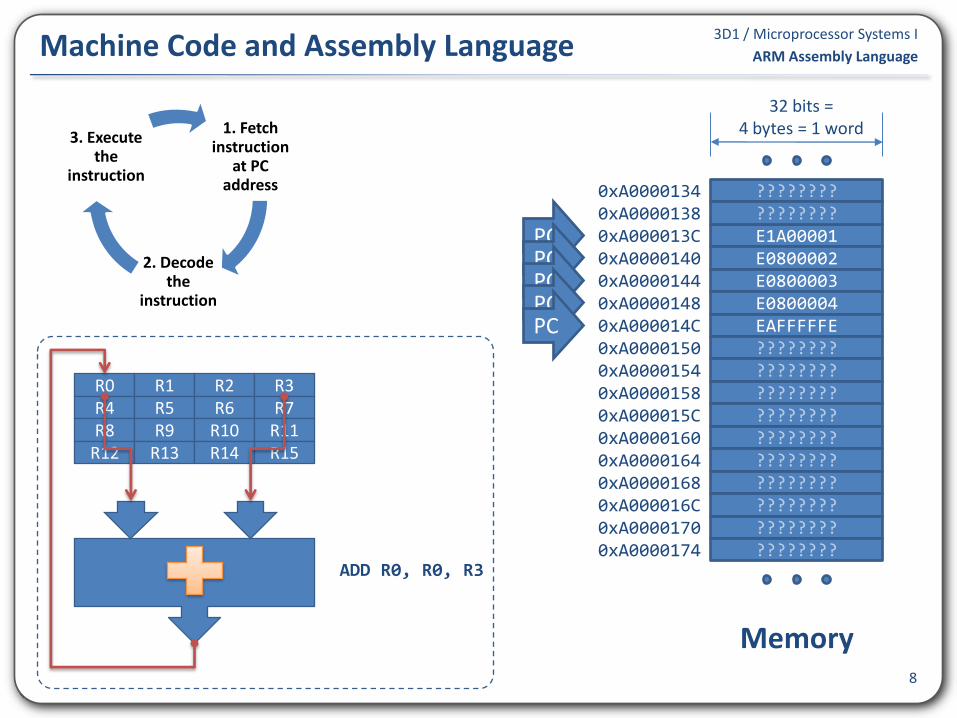
A program is composed of a sequence of instructions stored in memory as machine code• Instructions determine the operations performed by the
processor (e.g. add, move, multiply, subtract, compare, ...)
A single instruction is composed of• an operator (instruction)
• zero, one or more operands
e.g. ADD the values in r1 and r2 and store the result in r0• Operator is ADD
• Want to store the result in r0 (first operand)
• We want to add the values in r1 and r2 (second and third operands)
Each instruction and its operands are encoded using a unique value• e.g. 0xE0810002 is the machine that causes the processor to
add the values in r1 and r2 and store the result in r33
Machine Code and Assembly Language ARM Assembly Language

3D1 / Microprocessor Systems I
Writing programs using machine code is possible but not practical
Instead, we write programs using assembly language
• Instructions are expressed using mnemonics
4
Machine Code and Assembly Language ARM Assembly Language
• e.g. the word “ADD” instead of the machine code 0xE08
• e.g. the expression “r2” to refer to register number two, instead of the machine code value 0x2
Assembly language must still be translated into machine code
• Done using a program called an assembler
• Machine code produced by the assembler is stored in memory and executed by the processor

3D1 / Microprocessor Systems IProgram 1.1 revisited
5
ARM Assembly Language
start
MOV r0, r1 ; Make the first number the subtotal
ADD r0, r0, r2 ; Add the second number to the subtotal
ADD r0, r0, r3 ; Add the third number to the subtotal
ADD r0, r0, r4 ; Add the fourth number to the subtotal
stop B stop

3D1 / Microprocessor Systems IProgram 1.1 – Demonstration (Demo.lst)
6
ARM Assembly Language
1 00000000 AREA Demo, CODE, READONLY
2 00000000 IMPORT main
3 00000000 EXPORT start
4 00000000
5 00000000 start
6 00000000 E1A00001 MOV r0, r1
7 00000004 E0800002 ADD r0, r0, r2
8 00000008 E0800003 ADD r0, r0, r3
9 0000000C E0800004 ADD r0, r0, r4
10 00000010
11 00000010 EAFFFFFE
stop B stop
12 00000014
13 00000014 END
addresslinenumber
machinecode
original assembly language program

3D1 / Microprocessor Systems I
Every ARM machine code instruction is 32-bits long
32-bit instruction word must encode
• operation (instruction)
• all the required instruction operands
Example – add r0, r0, r2
7
Machine Code and Assembly Language ARM Assembly Language
1 1 1 0 0 0 0 0 1 0 0 0 Rn Rd Rm0 0 0 0 0 0 0 0
031 34111215161920
1 1 1 0 0 0 0 0 1 0 0 0 0 0 0 0 0 0 0 0 0 0 1 00 0 0 0 0 0 0 0
031 34111215161920
03
1 1 1 0 0 0 0 0 0 0 0 0 0 0 1 00 0 0 00 0 0 00 0 0 0 1 0 0 0
4781112151619202324272831
add Rd, Rn, Rm
E 0 0 2000 8
3D1 / Microprocessor Systems I
8
Machine Code and Assembly Language ARM Assembly Language
E1A00001E0800002E0800003E0800004EAFFFFFE
0xA00001440xA00001480xA000014C0xA00001500xA0000154
????????
0xA000013C0xA0000140
0xA00001580xA000015C0xA00001600xA00001640xA00001680xA000016C0xA00001700xA0000174
0xA00001340xA0000138
32 bits =4 bytes = 1 word
Memory
????????
????????????????????????????????????????????????????????????????????????????????
1. Fetch instruction
at PC address
2. Decode the
instruction
3. Execute the
instruction
PCPCPCPCPC
R0R4R8
R12
R1R5R9
R13
R2R6
R10R14
R3R7
R11R15
ADD R0, R0, R3

3D1 / Microprocessor Systems I
Start Debug Session
Program assembled and loaded into memory at a pre-defined address
Program Counter (PC) set to same pre-defined
address
Fetch-Decode-Execute cycle resumes
9
Program Execution ARM Assembly Language
0xA00000080xA000000C0xA00000100xA0000014
????????
0xA00000000xA0000004
0x9FFFFFF80x9FFFFFFC
32 bits =4 bytes = 1 word
Memory
????????
????????????????
PC ????????????????????????????????
E1A00001E0800002E0800003E0800004EAFFFFFEWhat happens
when we reach the end of our
program?

3D1 / Microprocessor Systems I
Write an assembly language program to swap the contents of register r0 and r1
10
Program 3.1 – Swap Registers ARM Assembly Language
startMOV r2, r0 ; temp <-- r0MOV r0, r1 ; r0 <-- r1MOV r1, r2 ; r1 <-- temp
stop B stop
startEOR r0, r0, r1 ; r0 <-- r0 xor r1EOR r1, r0, r1 ; r1 <-- (r0 xor r1) xor r1 = r0EOR r0, r0, r1 ; r0 <-- (r0 xor r1) xor r0 = r1
stop B stop
Compare both programs with respect
to instructions executed and registers
used ...

3D1 / Microprocessor Systems I
Register operands
Often want to use constant values as operands, instead of registers
• e.g. Move the value 0 (zero) into register r0
• e.g. Set r1 = r2 + 1
Called an immediate operand, syntax #x11
Immediate Operands ARM Assembly Language
ADD Rd, Rn, Rm
MOV Rd, Rm
ADD Rd, Rn, #x
MOV Rd, #x
MOV r0, #0 ; r0 <-- 0
ADD r1, r2, #1 ; r1 <-- r2 + 1

3D1 / Microprocessor Systems I
Write an assembly language program to compute ...
... if x is stored in r1. Store the result in r0
• Cannot use MUL to multiply by a constant value
• MUL Rx, Rx, Ry produces unpredictable results [UPDATE]
• r1 unmodified ... which may be something we want ... or not12
Program 3.2 – Simple Arithmetic ARM Assembly Language
startMUL r0, r1, r1 ; result <-- x * xLDR r2, =4 ; tmp <-- 4MUL r0, r2, r0 ; result <-- 4 * x * x
LDR r2, =3 ; tmp <-- 3MUL r2, r1, r2 ; tmp <-- x * tmp
ADD r0, r0, r1 ; result <-- result + tmp
stop B stop

3D1 / Microprocessor Systems I
Note use of operand =3
• Move constant value 3 into register r2
LoaD Register instruction can be used to load any 32-bit signed constant value into a register
Note use of =x syntax instead of #x with LDR instruction
13
LoaD Register ARM Assembly Language
... ... ...
LDR r2, =3 ; tmp <-- 3MUL r2, r1, r2 ; tmp <-- x * tmp
... ... ...
LDR r4, =0xA000013C ; r4 <-- 0xA000013C

3D1 / Microprocessor Systems I
Cannot fit large constant values in a 32-bit instruction
LDR is a “pseudo-instruction” that simplifies the implementation of a work-around for this limitation
For small constants, LDR is replaced with MOV14
MOV, LDR and Constant Values ARM Assembly Language
MOV r0, #7
6 00000000 E3A00007 MOV r0, #7
LDR r0, =7
6 00000000 E3A00007 LDR r0, =7
MOV r0, #0x4FE8
error: A1510E: Immediate 0x00004FE8 cannot be represented by 0-255 and a rotation
LDR r0, =0x4FE8
6 00000000 E59F0000 LDR r0, =0x4FE8

3D1 / Microprocessor Systems I
Provide meaningful comments and assume someone else will be reading your code
Break your programs into small pieces
While starting out, keep programs simple
Pay attention to initial values in registers (and memory)
15
Assembly Language Programming Guidelines ARM Assembly Language
MUL r2, r1, r2 ; r2 <-- r1 * r2
MUL r2, r1, r2 ; tmp <-- x * tmp

![Orbit Studies during ALBA Commissioning · 0 1 2 3 Horizontal [mm] mean rms max 0 1 2 3 Vertical 13 03 14 03 17 03 21 03 22 03 23 03 25 03 28 03 29 03 30 03 31 03 07 04 08 04 12 04](https://img.pdfslide.us/doc/110x75/60d5a0a03693bd125d57bcea/orbit-studies-during-alba-commissioning-0-1-2-3-horizontal-mm-mean-rms-max-0-1.jpg)