Embed Size (px)
Citation preview

Progress In Electromagnetics Research C, Vol. 25, 15–26, 2012
CRLH ZOR ANTENNA OF A CIRCULAR MICROSTRIPPATCH CAPACITIVELY COUPLED TO A CIRCULARSHORTED RING
S. Yoo and S. Kahng*
Department of Information and Telecommunication Engineering,University of Incheon, 12-1 Songdo-dong, Yeonsu-gu, Incheo 406-772,Korea
Abstract—In this paper, a novel Metamaterial (MTM) CRLH ZerothOrder Resonance (ZOR) Circular microstrip patch antenna is proposedto have a monopole antenna pattern due to the completely closed loopof a magnetic current around the structure, and reduced profile andsize due to the left-handedness. Different from other ZOR antennasof 1D periodic arrays with shorted patches, we suggest 1 circularpatch capacitively coupled to 1 circular shorted ring to have ZOR and−1st resonance modes. The antenna is designed and modeled withequivalent circuits for the coaxial-fed central patch and the circularshorted ring and verified by the comparison with 3D EM simulation ofthe physical structure. The no-phase variation at the ZOR (2.4GHz)and the −1st resonance mode (2 GHz) as the metamaterial propertiesare proven with electric field distributions and far-field patterns. Themeasurement shows there exist the ZOR and the −1 resonance modesdespite the frequency shift from the simulation, which is proven bythe monopolar radiation pattern and broadside radiation pattern,respectively. So the advantages of the proposed antenna will beaddressed with the low-profile monopole at the ZOR and the sizereduction effect at the −1st resonance.
1. INTRODUCTION
Portable devices for wireless communication are required to havesmaller RF components and antennas, while the high quality oftheir performances like multi-functions should be maintained. Theresearchers have sought and tried a number of approaches to
Received 28 July 2011, Accepted 28 September 2011, Scheduled 19 October 2011* Corresponding author: Sungtek Kahng ([email protected]).

16 Yoo and Kahng
circumvent the conflicts between the requirements on the size andfunction.
One of the latest ways to tackle the problem is taking advantage ofmetamaterial (MTM) structures. The MTM is artificially formed andengineered, showing negative or near zero or zero effective permittivity(εreff ) and permeability (µreff ). On the contrary to the phase delayfrom the Right-Handed (RH) wave with Double Positive εreff andµreff , (DPS), the Left-Handed (LH) wave with Double Negative εreff
and µreff , (DNG) results in phase-lead phenomenon. The differencebetween phase delay and phase lead in the Composite RH andLH (CRLH) determines the propagation number for Zeroth OrderResonance (ZOR), Negative resonance (NR), and Positive resonance(PR) of the structure. Specifically, the ZOR where no phase variationor infinite wavelength occurs and the Negative resonance are foundhelpful to the design of microwave components and antennas [1, 2].
Particularly, when the MTM is applied to antenna designs, CRLH-line cells are periodically arrayed to make leaky wave antennas orresonant ones [3–6]. ZOR CRLH antennas are brought up to obtainthe benefit of size-reduction [2–6]. Lai et al. and Lee et al. placemushrooms periodically in a 1D array with a line-feeding and showthe monopolar radiation pattern from a microstrip patch at the DNGZOR [3–5]. Instead of the DNG type ZOR, Kim et al. make theEpsilon Negative (ENG) ZOR antenna in the form of 1D periodicmushrooms [6]. Gomez-Diaz et al. put shorted metal strips closetogether in a longitudinal line to create leaky-wave radiation from afast-wave region of the dispersion characteristic [7]. Lee and Lee. madea 3X3 array of periodic mushrooms to enlarge magnetic current loopfor increasing the antenna gain [8]. Neither periodic nor an arrayform, Jang et al. coupled a half-wavelength rectangular patch toa rectangular ring having a few vias to make ZOR radiation withincreased antenna gain [9].
In this paper, we propose a new MTM antenna by transforminga circular patch of 2.4GHz PR to the DNG-type ZOR antennathrough capacitive coupling to 1 circular shorted ring. In otherwords, the positive half-wavelength resonance changes to the ZORphenomenon at the same frequency. As a result, it comes to have themonopolar far-field pattern at the ZOR frequency and the broadsideradiation pattern at the −1st resonance as the lower frequency aswell. For design and analysis, we use the equivalent circuits of theconventional PR and the attached circular shorted ring for the CRLHDNG, and we implement this antenna with a dielectric substratedifferent from [9] which uses the air under the patch to avoid possiblemechanical instability. It is validated by the 3D EM simulation,

Progress In Electromagnetics Research C, Vol. 25, 2012 17
the fabrication, and the measurement. Especially, the simulated andmeasured radiation patterns at the −1st resonance and the ZORwill prove the metamaterial properties of the proposed non-periodicMTM antenna along with the no-phase variation E-field at the ZORfrequency over the entire geometry, in spite of the frequency deviationof the experiment from the predicted S11. Finally, the antenna gain ofabout 2 dBi ∼ 5 dBi is mentioned along with the size-reduction effectby the −1st resonance mode and the ZOR in terms of the broadsideantenna pattern and low profile monopolar pattern.
2. EQUIVALENT CIRCUITS OF THE CIRCULARPATCH AND THE PROPOSED CRLH ZOR ANTENNA
To change the conventional half-wavelength Circular patch antennato the CRLH form, it is necessary to know the equivalent circuitsof the conventional patch antenna and the proposed circular shortedring. When the patch resonates at 2.4GHz with coaxial-feedingas in Fig. 1(a), it can be expressed with the equivalent circuit inFig. 1(b) where L1, L2 and C1 are calculated 1 nH, 0.2 nH and 4.6 pF,respectively. L1 and C1 account for the series inductance of thepatch surface and the shunt capacitance between the patch and theground. L2 mainly comes from the inner conductor of the coaxialfeed. At the resonance mode, say, half-wavelength resonance (λg/2)mode, the electric field is distributed as out-of-phase vectors at theopposite edges of the patch. This conventional antenna radiates fieldsin the broadside and in order to have the omni-directional radiationpattern in the azimuth plane, we need a metamaterial structure, and weshould change the circuit in Fig. 1(b) to Fig. 2 as the CRLH equivalentconfiguration.
In Fig. 2, series C (CL) plays the major role in changing theconventional patch to the CRLH antenna, which will be the couplingbetween the conventional patch and the proposed shorted ring. LL,
(a) (b)
R1
L2
Source
C1
L1
C1
L1
Figure 1. Conventional microstrip patch antenna. (a) Geometry,(b) equivalent circuit.

18 Yoo and Kahng
R1
L2
Source
CLLR L R
C RLL CR LL
Patch (Center)Metamaterial CRLH
C1C1
L1L1 C L
Figure 2. Equivalent circuit of the proposed CRLH microstripantenna.
1.6 1.8 2.0 2.2 2.4 2.6 2.8 3.0-30
-20
-10
0
Ret
urn
Loss
, d
B
Frequency, GHz
Initial parameter value Final parameter value
Figure 3. Conventional microstrip patch antenna: Return loss for theinitial and final values of Pr.
CR and LR are also necessary to make the complete CRLH combinedwith L1, C1, and L2. All the lumped elements are calculated to achievethe ZOR at 2.4 GHz, and L1, L2, C1, LR, CL, CR and LL are 1 nH,0.2 nH, 4.6 pF, 3 nH, 1.4 pF, 22 pF and 0.2 nH, respectively. From thefollowing equations, also shown in [10].
ωL =1√
LLCL, ωR =
1√LRCR
, ωse =1√
LRCL, ωsh =
1√LLCR
,
ω0 =√
ωRωL, ZL =√
LL
CL, ZR =
√LR
CR, Zse =
1− ω2LRCL
jωCL,
Zsh =jωLL
1− ω2LLCR
(1)
where ωL, ωR, ωse, and ωsh are cut-off frequencies for LH, RH, series,and shunt resonance, respectively, and the geometric average of thecut-off freqeuncies should be ω0 Also, ZL and ZR are set to thecharacteristic impedance.

Progress In Electromagnetics Research C, Vol. 25, 2012 19
CL, LL, CR and LR as the circuit elements will be realized withthe proposed geometry of the capacitive coupled circular shorted ring.
3. DESIGN RESULTS OF THE PROPOSED CRLH ZORANTENNA
Now the aforementioned equivalent circuits are changed to physicalgeometries. The initial geometrical dimensions can be obtainedthrough the approximate formulas for the circuit elements, as similarlydone in [9–11]. The initial geometries are drawn and adjusted inthe CST-MWS as a 3D EM field simulator to have the resonance atthe designated frequency. Pr is initially given by a formula from [9]concerned with λg/2. And Pr is iteratively varied in the field simulator.Its value is finalized as shown in Table 1.
Regarding the coaxial feeding, a circular patch of radius 23.4 mmis needed to resonate at 2.4 GHz. With the geometry of Fig. 1(a), thereturn loss is given as follows.
As expected, S11 of the conventional patch antenna has theresonance at 2.4 GHz with the finalized Pr as checked in Fig. 3. In thelater section of this paper, λg/2 E-field of the ordinary patch resonancemode will be presented.
It is time to illustrate and discuss the geometry of the proposedCRLH antenna. As mentioned earlier, the metamaterial antenna inthis paper uses the conventional circular patch as the central patch forL1, L2 and C1, and takes the circular shorted ring for CL, LL, CR andLR.
The shorted ring is made up of a metal strip loop supported byvias through the substrate from the ground. The surface of the metalstrip loop provides LR, and CR. The vias correspond to LL. Thegap between the central patch and the shorted ring explains CL. Ifthe gap is small, its size is obtained from the capacitance between theparallel lines. The length of the vias determines the height of the metalloop, which is the shunt inductance obtained through an approximate
Table 1. Conventional microstrip patch: radious.
Initial value Final valueResonance frequency 2.25GHz 2.4 GHz
Pr 24.7mm 23.4 mmSubstrate thickness 3.175 mm 3.175 mm
tan δ 0.0009 0.0009

20 Yoo and Kahng
formula.
Xp = ωLp = η0µr
(h
λ0
)[−γ + ln
(2√
µrεrk0a
)](2)
Through the iterative 3D EM simulations to meet the equivalentcircuit simulation result, the geometry is determined as follows.
As part of the process to find the final structure, we carry out theparametric studies that vary the physical dimensions and εr until thedesired result is obtained. First, we select the different values of εr
for the substrate. They are 1.0, 2.2 (RT Duroid 5880) and 4.4 (FR4).These numbers are realistic. Also, for the resonance at 2.4 GHz, thelength of the patch should be roughly inversely proportional to thedifferent εr. Here comes the return loss along with the gain at theresonance mode.
(a) (b)
(c)
Figure 4. Proposed ZOR patch antenna. (a) 3D view of the geometry,(b) top view, (c) circuit and EM simulations.

Progress In Electromagnetics Research C, Vol. 25, 2012 21
0 30 60 90 120 150 180 210 240 270 300 330 360-30
-20
-10
0
phi = 90 at air
phi = 90 at Rogers 5880
phi = 90 at FR 4
Gain
, d
B
Theta
(a) (b)
1.6 1.8 2.0 2.2 2.4 2.6 2.8 3.0-30
-20
-10
0
Air
Rogers 5880FR4
Ret
urn
Loss
, d
B
Frequency, GHz
Figure 5. Frequency response and antenna gain VS. different εr.(a) Return loss. (b) Radiation pattern at the ZOR VS. the elevationangle: Parameters are viar = 0.4mm, the number of the vias = 8,Rd = 0.1mm.
Table 2. Physical dimensions.
εr = 2.2, thickness = 3.175mm, metal thickeness = 1 oz,
W = L = 76.8mm, Pr = 23.4mm, Rw = 10mm,
Rd = 0.1mm, viap = 6 mm, viar = 0.4mm
and the number of the vias = 8
As shown in Fig. 5, all the three cases have both the ZOR and the−1st resonance mode, as the proposed CRLH antenna. The monopolarpatterns at 2.4 GHz in Fig. 5(b) prove the MTM ZOR characteristic.Since we set and fix 2.4 GHz as the ZOR for all the cases, they do notmove, but the −1st resonance mode varies upward with increasing εr.Besides, the ZOR radiation patterns show the higher εr becomes, thelower the antenna gain gets. Therefore, we choose εr = 2.2 for ourfinal design in terms of the size, the pattern and the antenna gain.
Next parametric studies go with the radius of the vias which isrelated to the number and distance of the vias and the distance betweena via and the outer edge of the metal loop, and Pr. The number ofthe vias is set 8, εr is 2.2, the gap is 0.1 mm. Fig. 6 presents theirfrequency responses.
When viar and viap are changed, they mainly affect the currentpath on the metal strip, thus LR. This causes the ZOR to move,while the −1st resonance mode barely changes, as shown in Figs. 6(a)and (b). When Pr becomes 18 mm, the−1st and ZOR frequencies moveupward as shown in Fig. 6(c), where the circuit and EM simulationshave very similar behaviors.
22 Yoo and Kahng
1.6 2.0 2.4 2.8 3.2 3.6-40
-30
-20
-10
0
Ret
urn
Loss
, d
B
Frequency, GHz
via_r = 0.2 mm
via_r = 0.4 mm
via_r = 0.6 mm
via_r = 0.8 mmvia_r = 1 mm
1.6 1.8 2.0 2.2 2.4 2.6 2.8 3.0-30
-20
-10
0
Ret
urn
Loss
, d
B
Frequency, GHz
viap =1mm
via
p
=3mm
via
p
=5mm
viap =71mm
1 2 3 4 5-25
-20
-15
-10
-5
0
EM Simulation result Circuit Simulation result
Ret
urn
Loss
(d
B)
Frequency (GHz)
(a) (b)
(c)
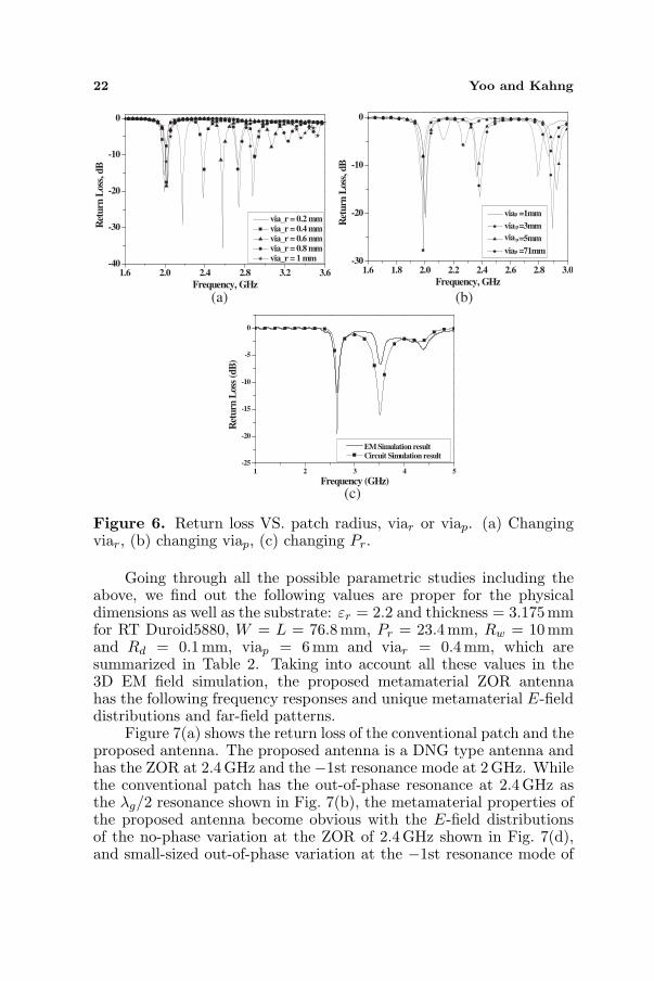
Figure 6. Return loss VS. patch radius, viar or viap. (a) Changingviar, (b) changing viap, (c) changing Pr.
Going through all the possible parametric studies including theabove, we find out the following values are proper for the physicaldimensions as well as the substrate: εr = 2.2 and thickness = 3.175mmfor RT Duroid5880, W = L = 76.8mm, Pr = 23.4mm, Rw = 10 mmand Rd = 0.1mm, viap = 6 mm and viar = 0.4 mm, which aresummarized in Table 2. Taking into account all these values in the3D EM field simulation, the proposed metamaterial ZOR antennahas the following frequency responses and unique metamaterial E-fielddistributions and far-field patterns.
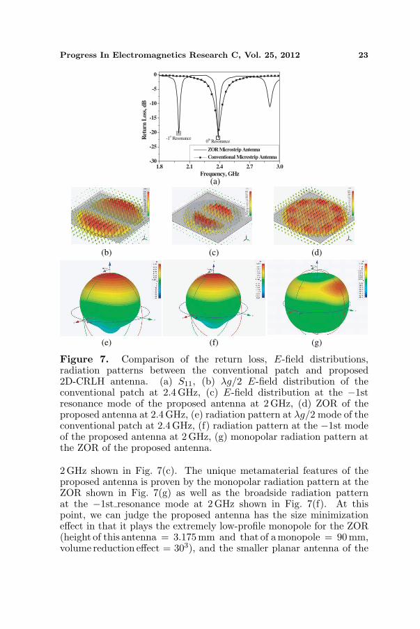
Figure 7(a) shows the return loss of the conventional patch and theproposed antenna. The proposed antenna is a DNG type antenna andhas the ZOR at 2.4GHz and the −1st resonance mode at 2 GHz. Whilethe conventional patch has the out-of-phase resonance at 2.4 GHz asthe λg/2 resonance shown in Fig. 7(b), the metamaterial properties ofthe proposed antenna become obvious with the E-field distributionsof the no-phase variation at the ZOR of 2.4 GHz shown in Fig. 7(d),and small-sized out-of-phase variation at the −1st resonance mode of
Progress In Electromagnetics Research C, Vol. 25, 2012 23
1.8 2.1 2.4 2.7 3.0-30
-25
-20
-15
-10
-5
0
0th Resonance
-1st ResonanceR
etu
rn L
oss
, d
B
Frequency, GHz
ZOR Microstrip Antenna
Conventional Micrestrip Antenna
(a)
(g)(f)(e)
(d)(c)(b)
Figure 7. Comparison of the return loss, E-field distributions,radiation patterns between the conventional patch and proposed2D-CRLH antenna. (a) S11, (b) λg/2 E-field distribution of theconventional patch at 2.4 GHz, (c) E-field distribution at the −1stresonance mode of the proposed antenna at 2 GHz, (d) ZOR of theproposed antenna at 2.4 GHz, (e) radiation pattern at λg/2 mode of theconventional patch at 2.4 GHz, (f) radiation pattern at the −1st modeof the proposed antenna at 2 GHz, (g) monopolar radiation pattern atthe ZOR of the proposed antenna.
2GHz shown in Fig. 7(c). The unique metamaterial features of theproposed antenna is proven by the monopolar radiation pattern at theZOR shown in Fig. 7(g) as well as the broadside radiation patternat the −1st resonance mode at 2 GHz shown in Fig. 7(f). At thispoint, we can judge the proposed antenna has the size minimizationeffect in that it plays the extremely low-profile monopole for the ZOR(height of this antenna = 3.175mm and that of a monopole = 90 mm,volume reduction effect = 303), and the smaller planar antenna of the

24 Yoo and Kahng
−1st resonance as the lower frequency having the broadside radiationpattern at a frequency below the ZOR frequency. Especially, to getgenerally useful radiation patterns and acceptable gain for differentfrequencies in one structure, the proposed antenna makes advantagesover the conventional combination of the individual 2 GHz antennaand the individual 2.4 GHz antenna, because a 2 GHz antenna has itsharmonic 4 GHz and it can not hold a slot for 2.4 GHz resonance whosesize exceeds the 2 GHz patch. This explains the size reduction by thenegative resonance of the proposed antenna.
Finally, the proposed antenna is fabricated with the same physicaldimensions and substrate as the 3D EM simulation above. Thusthe measurement of the physically implemented antenna presents thefollowing performances.
1.8 2.1 2.4 2.7 3.0-25
-20
-15
-10
-5
0
EM Simulation result
Measurement result
Circuit Simulation result
0th ResonanceR
etur
n L
oss
(dB
)
Frequency (GHz)
-1st Resonance
-30
-20
-10
0
100
30
60
90
120
150
180
210
240
270
300
330
-30
-20
-10
0
10
Simulation at phi = 90 degMeasurement at phi = 90 deg
-30
-20
-10
0
100
30
60
90
120
150
180
210
240
270
300
330
-30
-20
-10
0
10
Simulation at phi = 90 degMeasurement at phi = 90 deg
(a) (b)
(c) (d)
Figure 8. Measurement of the fabricated proposed 2D CRLHantenna. (a) Top and bottom views of the antenna. (b) Measured andsimulated S11. (c) Radiation pattern at the −1st mode of the proposedantenna, simulated at 2GHz and measured at 2.2 GHz. (d) Monopolarradiation pattern at the ZOR of the proposed antenna, simulated at2.4GHz and measured at 2.5 GHz.

Progress In Electromagnetics Research C, Vol. 25, 2012 25
Figure 8(a) is the photo of the fabricated antenna which looks thesame as Fig. 4(a). The return loss of this proposed antenna is measuredin the first place. The resonance frequencies (2.2 GHz and 2.5 GHz)of the measurement are shifted from those (2 GHz and 2.4 GHz) inthe circuit and EM simulation due to the manufacturing toleranceaffecting the gap, via radii, a real connector, gluing/soldering and εr
error (possibly non-uniform over the substrate slab and roughness)and test environment. Especially, the discrepancy is attributed to thechange in the gap from 0.1 mm to 0.17 mm. Despite the resonancefrequency shift, 2.2GHz and 2.5 GHz of the measurement still keep themetamaterial characteristics of 2 GHz and 2.4 GHz, respectively, whichis proven by the radiation patterns that are generated for the −1stresonance and ZOR modes. The monopolar pattern of gain 2.36 dBiis achieved at 2.5 GHz shifted from the ZOR at 2.4GHz. Besides,the −1st resonance mode far-field pattern of gain 2.23 dBi is obtainedat 2.2 GHz in the measurement the same as that of 2 GHz in thesimulation.
4. CONCLUSION
In this paper, a novel metamaterial CRLH ZOR Circular microstrippatch antenna is proposed, which comprises 1 circular patchcapacitively coupled to 1 circular ring mushroom to have a monopoleantenna pattern due to the completely closed loop of a magneticcurrent around the structure, and reduced profile and size due tothe Left-handedness. The antenna is designed and modeled withthe equivalent circuits and verified by the 3D EM simulation of thephysical structure. The no-phase variation at the ZOR and the −1stresonance mode are proven with electric field distributions and far-field patterns. The measurement shows there exist the ZOR and the−1 resonance mode despite the frequency shift from the simulation,which is proven by the monopolar pattern and broadside radiation,respectively. Also the proposed antenna turns out effective in sizeminimization as the low-profile monopole at the ZOR and the lowerfrequency resonance at a higher frequency size. Hence, the suggesteddesign method will be applicable to the antennas for surface mountablevehicles and miniaturized wireless communication systems.
ACKNOWLEDGMENT
This work was supported by the research promotion program of theuniversity of Incheon in 2011.

26 Yoo and Kahng
REFERENCES
1. Caloz, C. and T. Itoh, Electromagnetic Metamaterials: Trans-mission Line Theory and Microwave Application, Wiley & Sons,2006.
2. Jang, G. and S. Kahng, “Design of a metamaterial bandpassfilter using the zor of a modified circular mushroom structure,”Microwave Journal, Vol. 54, No. 5, 158–167, May 2011.
3. Lai, A., C. Caloz, and T. Itoh, “Composite right/left-handedtransmission line metamaterials,” IEEE Microwave Magazine,Vol. 5, No. 3, 34–50, Sep. 2004.
4. Lee, C.-J., K. M. K. H. Leong, and T. Itoh, “Composite right/left-handed transmission line based compact resonant antennas for RFmodule integration,” IEEE Trans. on Antennas and Propagat.,Vol. 54, 2283–2291, Aug. 2006.
5. Lai, A., K. M. K. H. Leong, and T. Itoh, “Infinite wavelengthresonant antennas with monopolar radiation patterns based onperiodic structures,” IEEE Trans. on Antennas Propagat., Vol. 55,No. 3, 868–876, Mar. 2007.
6. Kim, J. and J. Choi, “Dual band MIMO antenna using ENGzeroth order resonator for 4G system,” IEEE InternationalWorkshop on Antenna Technology, iWAT, 1–4, Oct. 2009.
7. Gomez-Diaz, J. S., A. Alvarez-Melcon, and T. Bertuch, “Amodal-based iterative circuit model for the analysis of crlhleaky-wave antennas comprising periodically loaded PPW,” IEEETransactions on Antennas and Propagation, Vol. 59, No. 4, 1101–1112, Apr. 2011.
8. Lee, J.-G. and J.-H. Lee “Zeroth order resonance loop antenna,”IEEE Trans. on Antennas and Propagat., Vol. 55, No. 3, 994–997,Mar. 2007.
9. Jang, G., S. Kahng, J. Ju, J. Anguera, and J. Choi, “A novelmetamaterial CRLH ZOR microstrip patch antenna capacitivleycoupled to a rectangular ring,” IEEE Antennas and PropagationSociety International Symposium (APSURSI), Toronto, Jul. 11–17, 2010.
10. Jang, G. and S. Kahng, “Design of a dual-band metamaterialbandpass filter using zeroth order resonance,” Progress InElectromagnetics Research C, Vol. 12, 149–162, 2010.
11. Balanis, A., Antenna Theory: Analysis and Design, John Wiley& Sons, 1997.


