Embed Size (px)
Citation preview
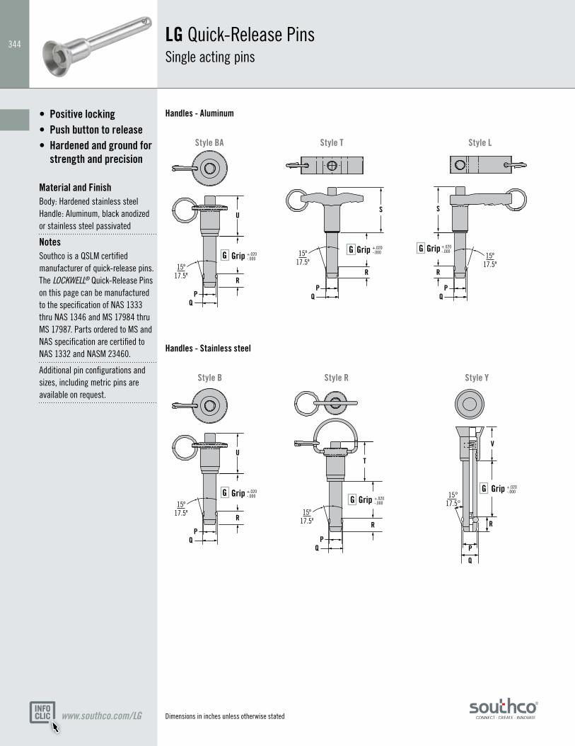
344LG Quick-Release Pins Single acting pins
Positive locking•Push button to release•Hardened and ground for •
strength and precision
Material and FinishBody: Hardened stainless steel Handle: Aluminum, black anodized or stainless steel passivated
NotesSouthco is a QSLM certified manufacturer of quick-release pins. The LOCKWELL® Quick-Release Pins on this page can be manufactured to the specification of NAS 1333 thru NAS 1346 and MS 17984 thru MS 17987. Parts ordered to MS and NAS specification are certified to NAS 1332 and NASM 23460.
Additional pin configurations and sizes, including metric pins are available on request.
www.southco.com/LG
Handles - Aluminum
Style R
Style L
Style B Style Y
R
15°17.5°
P
Q
QP
QP
QP
QP
R R
S S
RR
U
T
V
15º17.5º
15º17.5º 15º
17.5º
15º17.5º
GripGGripGGripG
GripG GripG+.020 -.000
+.020 -.000
+.020 -.000
+.020 -.000
+.020 -.000
R
15°17.5°
P
Q
QP
QP
QP
QP
R R
S S
RR
U
T
V
15º17.5º
15º17.5º 15º
17.5º
15º17.5º
GripGGripGGripG
GripG GripG+.020 -.000
+.020 -.000
+.020 -.000
+.020 -.000
+.020 -.000
R
15°17.5°
P
Q
QP
QP
QP
QP
R R
S S
RR
U
T
V
15º17.5º
15º17.5º 15º
17.5º
15º17.5º
GripGGripGGripG
GripG GripG+.020 -.000
+.020 -.000
+.020 -.000
+.020 -.000
+.020 -.000
R
15°17.5°
P
Q
QP
QP
QP
QP
R R
S S
RR
U
T
V
15º17.5º
15º17.5º 15º
17.5º
15º17.5º
GripGGripGGripG
GripG GripG+.020 -.000
+.020 -.000
+.020 -.000
+.020 -.000
+.020 -.000
R
15°17.5°
P
Q
QP
QP
QP
QP
R R
S S
RR
U
T
V
15º17.5º
15º17.5º 15º
17.5º
15º17.5º
GripGGripGGripG
GripG GripG+.020 -.000
+.020 -.000
+.020 -.000
+.020 -.000
+.020 -.000
Style T
Handles - Stainless steel
Style BA
R
15°17.5°
P
Q
QP
QP
QP
QP
R R
S S
RR
U
T
V
15º17.5º
15º17.5º 15º
17.5º
15º17.5º
GripGGripGGripG
GripG GripG+.020 -.000
+.020 -.000
+.020 -.000
+.020 -.000
+.020 -.000
Dimensions in inches unless otherwise stated
345
www.southco.com/LG
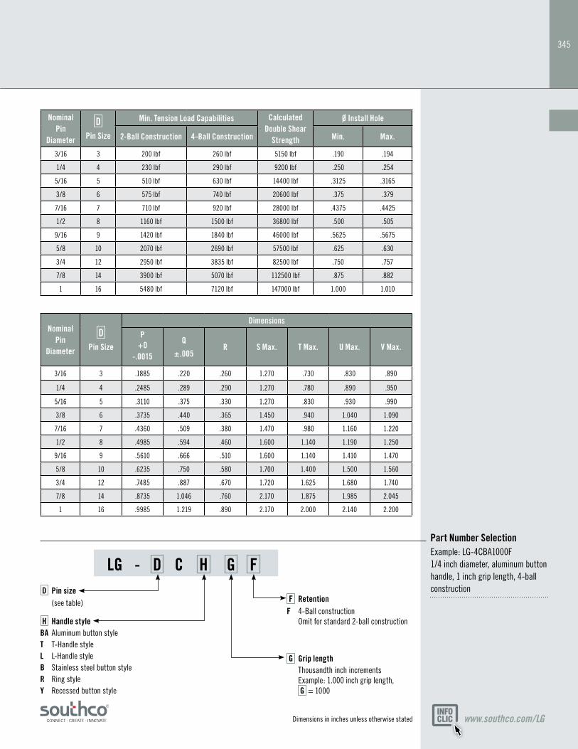
LG - D C H G F
Part Number SelectionExample: LG-4CBA1000F 1/4 inch diameter, aluminum button handle, 1 inch grip length, 4-ball construction
Nominal Pin
Diameter
D
Pin Size
Dimensions
P+0
-.0015
Q
±.005R S Max. T Max. U Max. V Max.
3/16 3 .1885 .220 .260 1.270 .730 .830 .890
1/4 4 .2485 .289 .290 1.270 .780 .890 .950
5/16 5 .3110 .375 .330 1.270 .830 .930 .990
3/8 6 .3735 .440 .365 1.450 .940 1.040 1.090
7/16 7 .4360 .509 .380 1.470 .980 1.160 1.220
1/2 8 .4985 .594 .460 1.600 1.140 1.190 1.250
9/16 9 .5610 .666 .510 1.600 1.140 1.410 1.470
5/8 10 .6235 .750 .580 1.700 1.400 1.500 1.560
3/4 12 .7485 .887 .670 1.720 1.625 1.680 1.740
7/8 14 .8735 1.046 .760 2.170 1.875 1.985 2.045
1 16 .9985 1.219 .890 2.170 2.000 2.140 2.200
H Handle styleBA Aluminum button styleT T-Handle style L L-Handle style B Stainless steel button styleR Ring styleY Recessed button style
G Grip length Thousandth inch increments Example: 1.000 inch grip length, G = 1000
Nominal Pin
Diameter
D
Pin Size
Min. Tension Load Capabilities Calculated Double Shear
Strength
Ø Install Hole
2-Ball Construction 4-Ball Construction Min. Max.
3/16 3 200 lbf 260 lbf 5150 lbf .190 .194
1/4 4 230 lbf 290 lbf 9200 lbf .250 .254
5/16 5 510 lbf 630 lbf 14400 lbf .3125 .3165
3/8 6 575 lbf 740 lbf 20600 lbf .375 .379
7/16 7 710 lbf 920 lbf 28000 lbf .4375 .4425
1/2 8 1160 lbf 1500 lbf 36800 lbf .500 .505
9/16 9 1420 lbf 1840 lbf 46000 lbf .5625 .5675
5/8 10 2070 lbf 2690 lbf 57500 lbf .625 .630
3/4 12 2950 lbf 3835 lbf 82500 lbf .750 .757
7/8 14 3900 lbf 5070 lbf 112500 lbf .875 .882
1 16 5480 lbf 7120 lbf 147000 lbf 1.000 1.010
F RetentionF 4-Ball construction Omit for standard 2-ball construction
D Pin size (see table)
Dimensions in inches unless otherwise stated
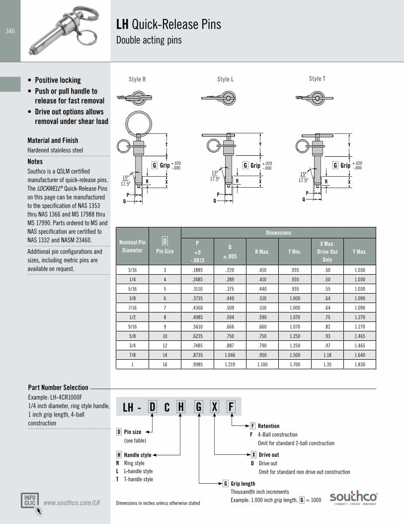
346LH Quick-Release Pins Double acting pins
Positive locking•Push or pull handle to •
release for fast removalDrive out options allows •
removal under shear load Material and FinishHardened stainless steel
NotesSouthco is a QSLM certified manufacturer of quick-release pins. The LOCKWELL® Quick-Release Pins on this page can be manufactured to the specification of NAS 1353 thru NAS 1366 and MS 17988 thru MS 17990. Parts ordered to MS and NAS specification are certified to NAS 1332 and NASM 23460.
Additional pin configurations and sizes, including metric pins are available on request.
www.southco.com/LH
Style R Style TStyle L
LH - D C H G X F
Part Number SelectionExample: LH-4CR1000F 1/4 inch diameter, ring style handle, 1 inch grip length, 4-ball construction
R X
T
R X
Y
R X
Y
QP
QP
15º17.5º
15º17.5º
QP
15º17.5º
Grip GGrip G GripG+.020-.000
+.020-.000
+.020-.000
Nominal Pin Diameter
D
Pin Size
Dimensions
P
+0 -.0015
Q
±.005R Max. T Min.
X Max. Drive Out
OnlyY Max.
3/16 3 .1885 .220 .410 .935 .50 1.030
1/4 4 .2485 .289 .410 .935 .50 1.030
5/16 5 .3110 .375 .440 .935 .55 1.030
3/8 6 .3735 .440 .510 1.000 .64 1.090
7/16 7 .4360 .509 .510 1.000 .64 1.090
1/2 8 .4985 .594 .590 1.070 .75 1.270
9/16 9 .5610 .666 .660 1.070 .82 1.270
5/8 10 .6235 .750 .750 1.250 .93 1.465
3/4 12 .7485 .887 .790 1.250 .97 1.465
7/8 14 .8735 1.046 .950 1.500 1.18 1.640
1 16 .9985 1.219 1.100 1.700 1.35 1.830
H Handle style R Ring style L L-handle styleT T-handle style
G Grip length Thousandth inch increments Example: 1.000 inch grip length, G = 1000
D Pin size (see table)
F RetentionF 4-Ball construction Omit for standard 2-ball construction
X Drive outD Drive out Omit for standard non drive out construction
Dimensions in inches unless otherwise stated
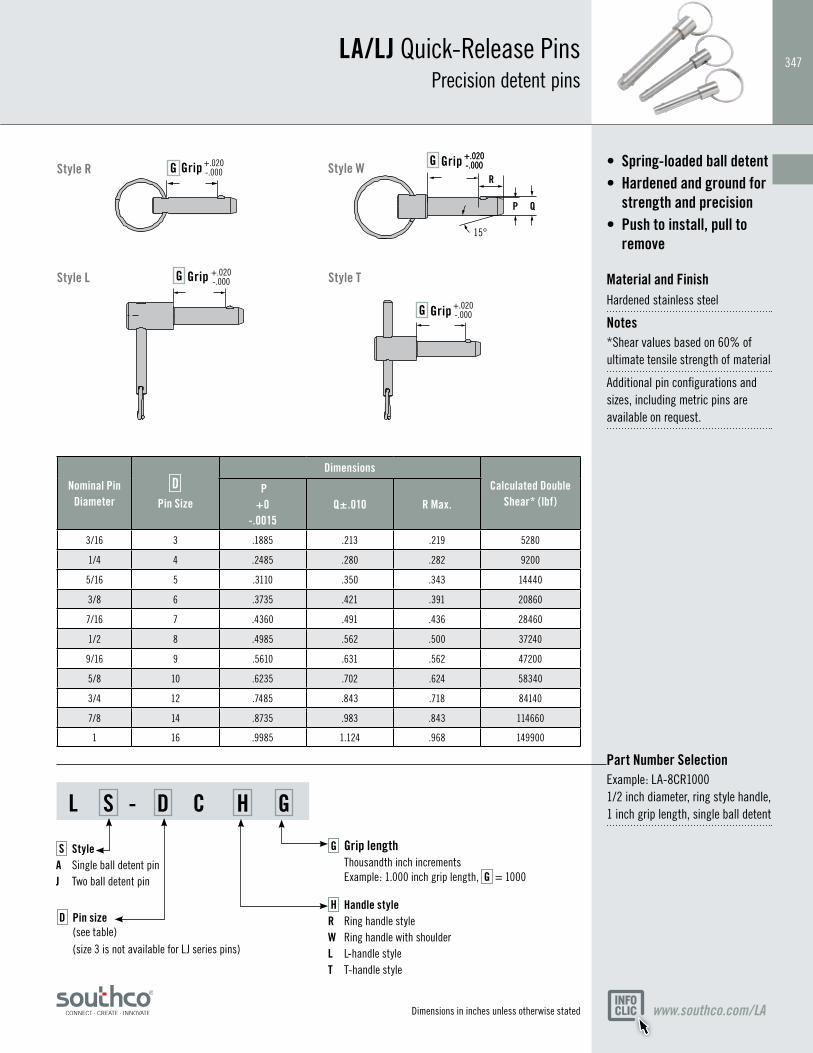
347LA/LJ Quick-Release Pins
Precision detent pins
Spring-loaded ball detent•Hardened and ground for •
strength and precisionPush to install, pull to •
remove Material and FinishHardened stainless steel
Notes*Shear values based on 60% of ultimate tensile strength of material
Additional pin configurations and sizes, including metric pins are available on request.
www.southco.com/LA
Style R
Style L Style T
L S - D C H G
Part Number SelectionExample: LA-8CR1000 1/2 inch diameter, ring style handle, 1 inch grip length, single ball detent
Nominal Pin Diameter
D
Pin Size
DimensionsCalculated Double
Shear* (lbf) P +0
-.0015Q±.010 R Max.
3/16 3 .1885 .213 .219 5280
1/4 4 .2485 .280 .282 9200
5/16 5 .3110 .350 .343 14440
3/8 6 .3735 .421 .391 20860
7/16 7 .4360 .491 .436 28460
1/2 8 .4985 .562 .500 37240
9/16 9 .5610 .631 .562 47200
5/8 10 .6235 .702 .624 58340
3/4 12 .7485 .843 .718 84140
7/8 14 .8735 .983 .843 114660
1 16 .9985 1.124 .968 149900
+.020-.000
R
QP
15°
GG
G
G
+.020-.000
Grip Grip
Grip
Grip
+.020-.000
+.020-.000
+.020-.000
H Handle styleR Ring handle style W Ring handle with shoulderL L-handle style T T-handle style
D Pin size (see table) (size 3 is not available for LJ series pins)
G Grip length Thousandth inch increments Example: 1.000 inch grip length, G = 1000
S StyleA Single ball detent pinJ Two ball detent pin
Dimensions in inches unless otherwise stated
Style W
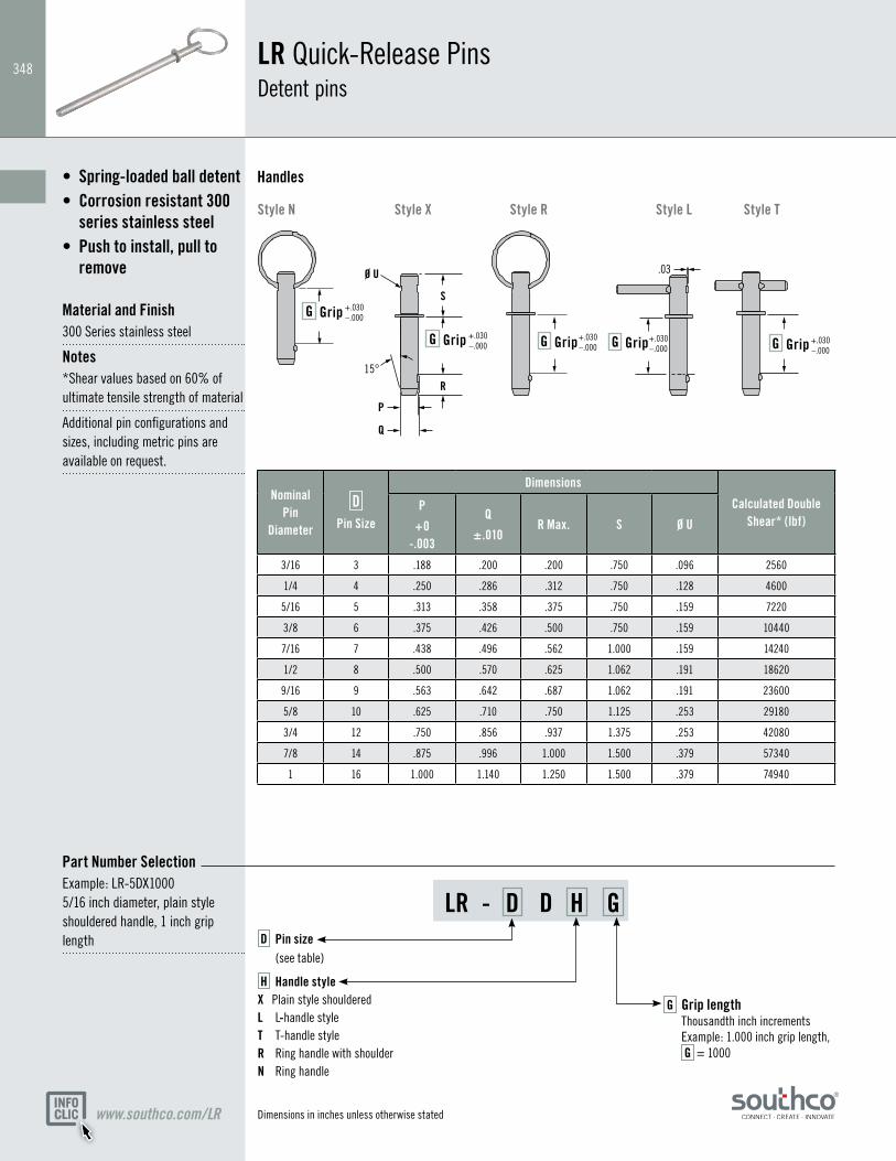
348
LR - D D H G
LR Quick-Release Pins Detent pins
www.southco.com/LR
H Handle style X Plain style shoulderedL L-handle styleT T-handle styleR Ring handle with shoulderN Ring handle
G Grip length Thousandth inch increments Example: 1.000 inch grip length, G = 1000
D Pin size (see table)
Spring-loaded ball detent•Corrosion resistant 300 •
series stainless steelPush to install, pull to •
remove Material and Finish300 Series stainless steel
Notes*Shear values based on 60% of ultimate tensile strength of material
Additional pin configurations and sizes, including metric pins are available on request.
Style N Style X Style R Style L Style T
Part Number SelectionExample: LR-5DX1000 5/16 inch diameter, plain style shouldered handle, 1 inch grip length
Nominal Pin
Diameter
D
Pin Size
Dimensions
Calculated Double Shear* (lbf)
P
+0 -.003
Q
±.010R Max. S Ø U
3/16 3 .188 .200 .200 .750 .096 2560
1/4 4 .250 .286 .312 .750 .128 4600
5/16 5 .313 .358 .375 .750 .159 7220
3/8 6 .375 .426 .500 .750 .159 10440
7/16 7 .438 .496 .562 1.000 .159 14240
1/2 8 .500 .570 .625 1.062 .191 18620
9/16 9 .563 .642 .687 1.062 .191 23600
5/8 10 .625 .710 .750 1.125 .253 29180
3/4 12 .750 .856 .937 1.375 .253 42080
7/8 14 .875 .996 1.000 1.500 .379 57340
1 16 1.000 1.140 1.250 1.500 .379 74940
P
Q
R
S
Ø U
15°
Grip
.03
G GripG GripG GripG
GripG +.030–.000
+.030–.000
+.030–.000
+.030–.000
+.030–.000
Handles
Dimensions in inches unless otherwise stated
349
Other options available. For complete details on variety, part numbers, installation and specification, go to
Other options available. For complete details on variety, part numbers, installation and specification, go to
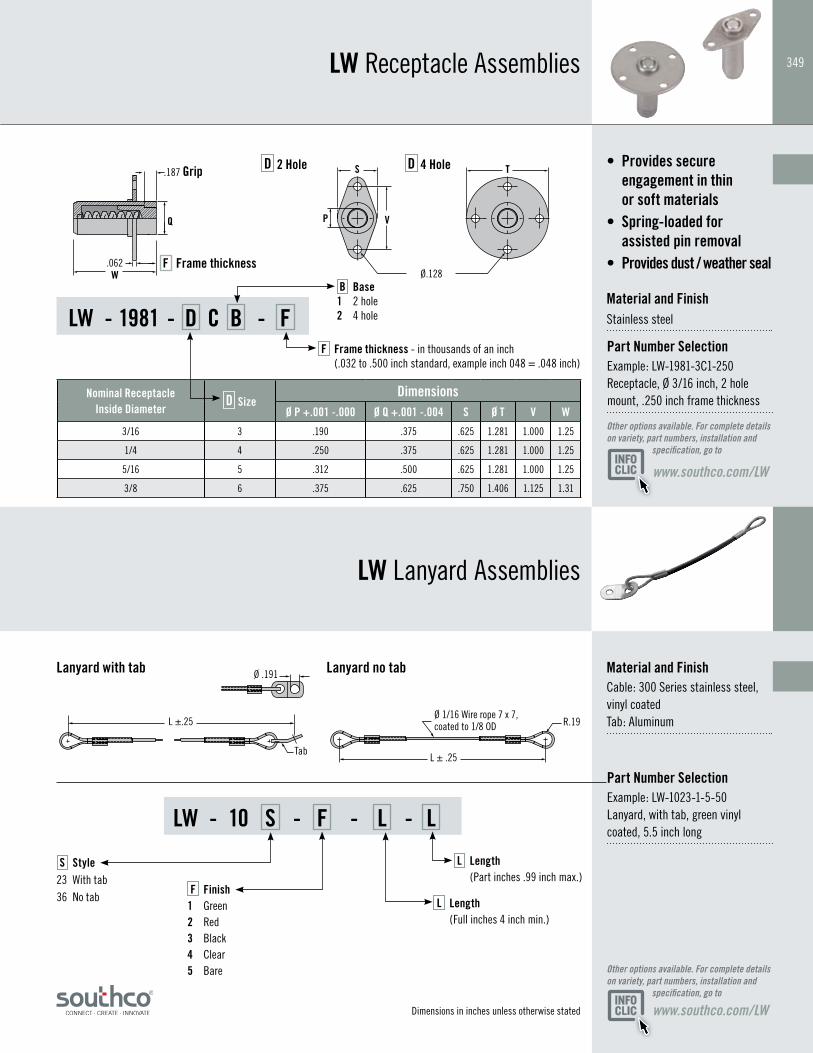
LW Receptacle Assemblies
LW Lanyard Assemblies
Material and FinishCable: 300 Series stainless steel, vinyl coated Tab: Aluminum
Provides secure • engagement in thin or soft materials
Spring-loaded for • assisted pin removal
Provides dust / weather seal• Material and FinishStainless steel
www.southco.com/LW
www.southco.com/LW
D 2 Hole D 4 Hole
Lanyard with tab Lanyard no tab
LW - 10 S - F - L - L
LW - 1981 - D C B - F
Part Number SelectionExample: LW-1023-1-5-50 Lanyard, with tab, green vinyl coated, 5.5 inch long
Part Number SelectionExample: LW-1981-3C1-250 Receptacle, Ø 3/16 inch, 2 hole mount, .250 inch frame thickness
F Finish 1 Green2 Red3 Black4 Clear5 Bare
B Base 1 2 hole 2 4 hole
S Style23 With tab36 No tab L Length
(Full inches 4 inch min.)
F Frame thickness - in thousands of an inch (.032 to .500 inch standard, example inch 048 = .048 inch)
Tab
L ±.25
Ø .191
Ø 1/16 Wire rope 7 x 7, coated to 1/8 OD R.19
L ± .25
Q P V
S T
W Ø.128.062 Frame thicknessF
.187 Grip
Nominal Receptacle Inside Diameter
D SizeDimensions
Ø P +.001 -.000 Ø Q +.001 -.004 S Ø T V W
3/16 3 .190 .375 .625 1.281 1.000 1.25
1/4 4 .250 .375 .625 1.281 1.000 1.25
5/16 5 .312 .500 .625 1.281 1.000 1.25
3/8 6 .375 .625 .750 1.406 1.125 1.31
L Length (Part inches .99 inch max.)
Dimensions in inches unless otherwise stated


![Max. Holding Capacity N[lbf.] mm [inch]](https://img.pdfslide.us/doc/110x75/6230327c0f03ee649506ccca/max-holding-capacity-nlbf-mm-inch.jpg)