Embed Size (px)
Citation preview

Monroe L. Weber-Shirk
School of Civil and
Environmental Engineering
Pipe Networks
Pipeline systemsTransmission linesPipe networksMeasurementsManifolds and diffusersPumpsTransients
You are here

Pipeline systems:Pipe networks
Water distribution systems for municipalities Multiple sources and multiple sinks connected
with an interconnected network of pipes. Computer solutions!
KYpipesWaterCADCyberNETEPANET http://www.epa.gov/ORD/NRMRL/wswrd/epanet.html

Water Distribution System Assumption
Each point in the system can only have one _______
The pressure change from 1 to 2 by path a must equal the pressure change from 1 to 2 by path b
a
p1
γ+
V12
2g+ z1 =
p2
γ+
V22
2g+ z2 + hL
p2
γ−
p1
γ=
V1a
2
2g+ z1 −
V2 a
2
2g− z2 − hLa
b
1 2pressure
Same for path b!

hLa= hLb
a
b
1 2Pressure change by path a
Water Distribution System Assumption
Pipe diameters are constant or K.E. is smallModel withdrawals as occurring at nodes so
V is constant between nodes
Or sum of head loss around loop is _____.zero(Need a sign convention)
V1a
2
2g+ z1 −
V2a
2
2g− z2 − hL a
=V1b
2
2g+ z1 −
V2 b
2
2g− z2 − hLb

Pipes in Parallel
A B
Q1
Qtotal
energy
proportion
Find discharge given pressure at A and B______& ____ equationadd flows
Find head loss given the total flowassume a discharge Q1’ through pipe 1
solve for head loss using the assumed discharge
using the calculated head loss to find Q2’
assume that the actual flow is divided in the same _________ as the assumed flow
Q2
S-J
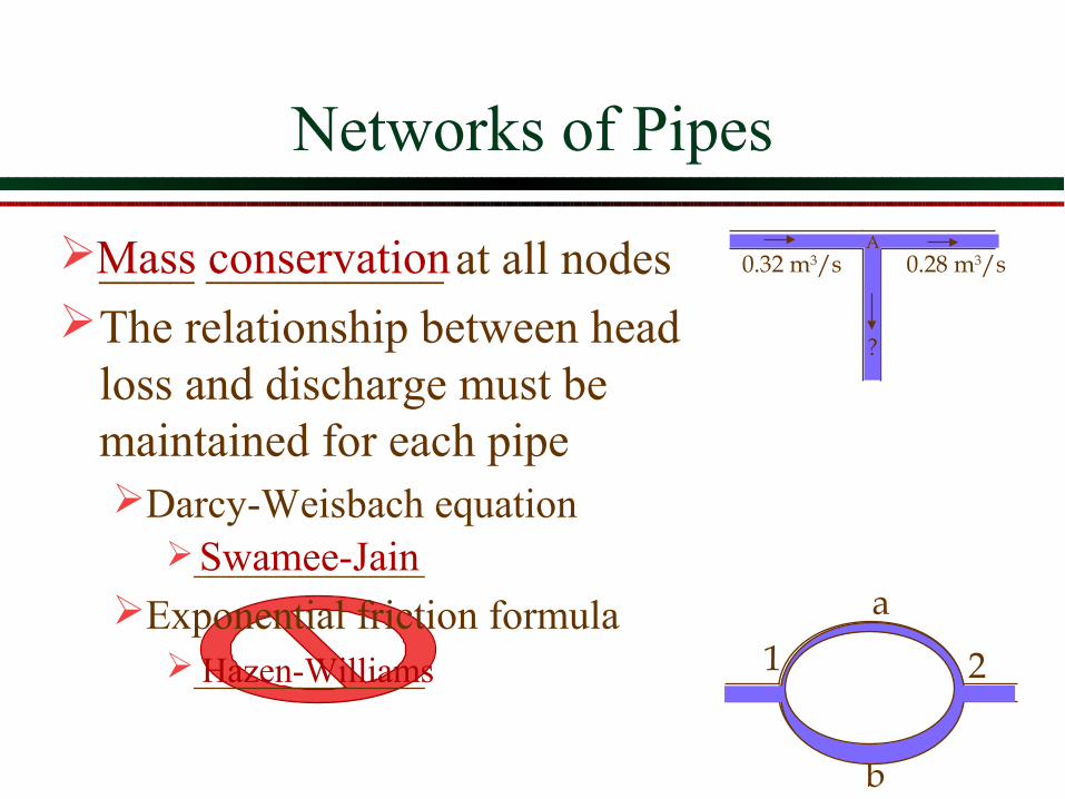
Networks of Pipes
____ __________ at all nodesThe relationship between head
loss and discharge must be maintained for each pipe Darcy-Weisbach equation
_____________
Exponential friction formula_____________
A0.32 m3/s 0.28 m3/s
?
b
a
1 2
Mass conservation
Swamee-Jain
Hazen-Williams

Network Analysis
Find the flows in the loop given the inflows and outflows.The pipes are all 25 cm cast iron (ε=0.26 mm).
A B
C D0.10 m3/s
0.32 m3/s 0.28 m3/s
0.14 m3/s200 m
100 m

Network Analysis
Assign a flow to each pipe link Flow into each junction must equal flow out
of the junction
A B
C D0.10 m3/s
0.32 m3/s 0.28 m3/s
0.14 m3/s
0.320.00
0.10
0.04
arbitrary

Network Analysis
Calculate the head loss in each pipe
f=0.02 for Re>200000 hf =
8 fLgD5π 2
Q2
fh kQ Q=
339)25.0)(8.9(
)200)(02.0(825
1 =
=
πk
k1,k3=339k2,k4=169
A B
C D0.10 m3/s
0.32 m3/s 0.28 m3/s
0.14 m3/s
1
4 2
3
hf1= 34.7m
hf2= 0.222m
hf3= −3.39m
hf4= −0.00m
hfi
i=1
4
∑ = 31.53m
Sign convention +CW2
5
s
m

Network Analysis
The head loss around the loop isn’t zero Need to change the flow around the loop
the ___________ flow is too great (head loss is positive)
reduce the clockwise flow to reduce the head loss
Solution techniquesHardy Cross loop-balancing (___________ _________)Use a numeric solver (Solver in Excel) to find a change
in flow that will give zero head loss around the loopUse Network Analysis software (EPANET)
clockwise
optimizes correction

Numeric Solver
Set up a spreadsheet as shown below. the numbers in bold were entered, the other cells are
calculations initially ∆Q is 0 use “solver” to set the sum of the head loss to 0 by changing ∆Q
the column Q0+ ∆Q contains the correct flows
∆Q 0.000pipe f L D k Q0 Q0+∆Q hfP1 0.02 200 0.25 339 0.32 0.320 34.69P2 0.02 100 0.25 169 0.04 0.040 0.27P3 0.02 200 0.25 339 -0.1 -0.100 -3.39P4 0.02 100 0.25 169 0 0.000 0.00
31.575Sum Head Loss

Solution to Loop Problem
A B
C D0.10 m3/s
0.32 m3/s 0.28 m3/s
0.14 m3/s
0.218
0.102
0.202
0.062
1
4 2
3
Q0+ ∆Q 0.218−0.062−0.202−0.102
Better solution is software with a GUI showing the pipe network.

Network Elements
ControlsCheck valve (CV)Pressure relief valvePressure reducing valve (PRV)Pressure sustaining valve (PSV)Flow control valve (FCV)
Pumps: need a relationship between flow and head Reservoirs: infinite source, elevation is not
affected by demand Tanks: specific geometry, mass conservation
applies

Check Valve
Valve only allows flow in one directionThe valve automatically closes when flow
begins to reverse
closedopen
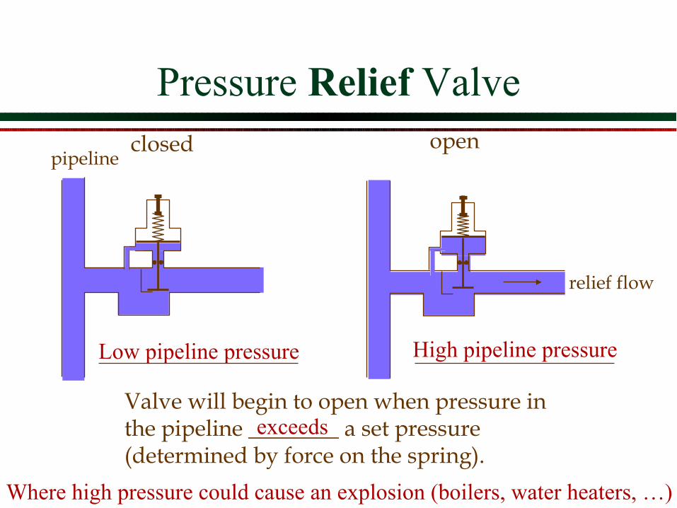
Pressure Relief Valve
Valve will begin to open when pressure in the pipeline ________ a set pressure (determined by force on the spring).
pipelineclosed
relief flow
open
exceeds
Low pipeline pressure High pipeline pressure
Where high pressure could cause an explosion (boilers, water heaters, …)
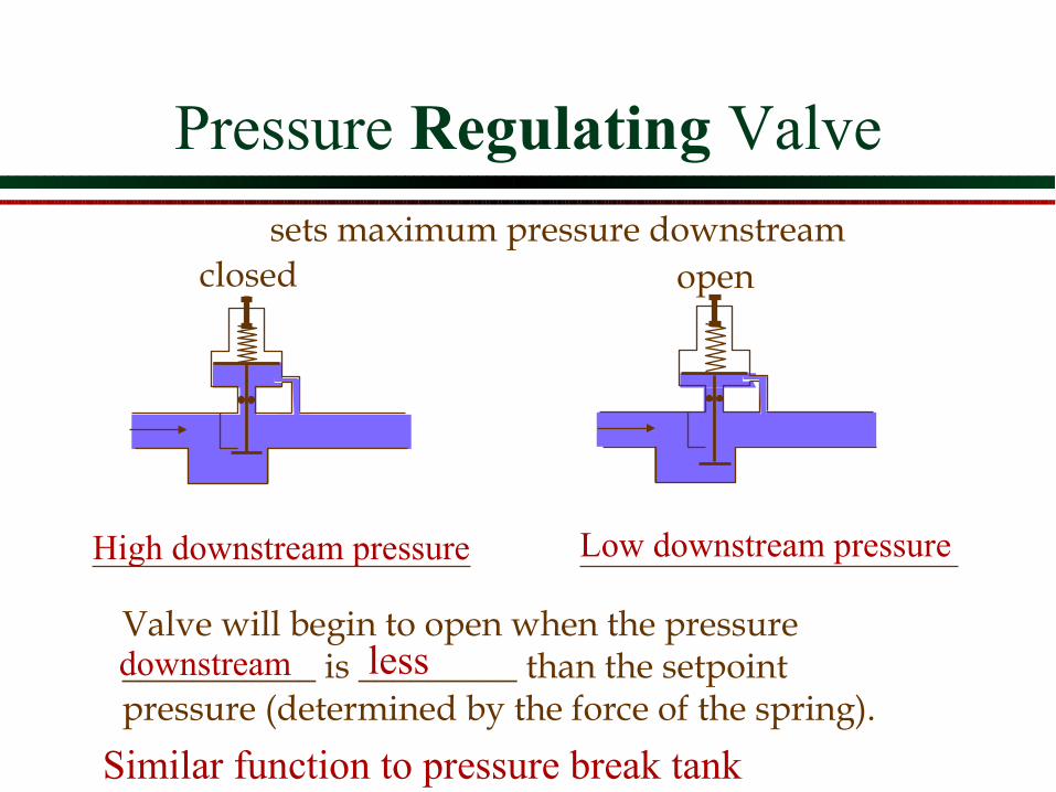
Pressure Regulating Valve
Valve will begin to open when the pressure ___________ is _________ than the setpoint pressure (determined by the force of the spring).
sets maximum pressure downstreamclosed open
lessdownstream
High downstream pressure Low downstream pressure
Similar function to pressure break tank

Pressure Sustaining Valve
Valve will begin to open when the pressure ________ is _________ than the setpoint pressure (determined by the force of the spring).
sets minimum pressure upstream
closed open
upstream greater
Low upstream pressure High upstream pressure
Similar to pressure relief valve

Flow control valve (FCV)
Limits the ____ ___ through the valve to a specified value, in a specified direction
Commonly used to limit the maximum flow to a value that will not adversely affect the provider’s system
flow rate

Pressure Break Tanks
In the developing world small water supplies in mountainous regions can develop too much pressure for the PVC pipe.
They don’t want to use PRVs because they are too expensive and are prone to failure.
Pressure break tanks have an inlet, an outlet, and an overflow.
Is there a better solution?

Network Analysis Extended
The previous approach works for a simple loop, but it doesn’t easily extend to a whole network of loops
Need a matrix methodInitial guess for flowsAdjust all flows to reduce the error in pressures __________________________ _______________________________
Simultaneous equations
Appendix D of EPANET manual

Pressure Network Analysis Software: EPANET
A B
C D0.10 m3/s
0.32 m3/s 0.28 m3/s
0.14 m3/s
0.218
0.102
0.202
0.062
1
4 2
3
junctionpipereservoir

EPANET network solution
2ni j ij ij ijH H h rQ mQ− = = +
0ij ij
Q D− =∑
AH = F
ii ijj
A p= ∑ij ijA p= −
1
1
2ij n
ij ij
pnr Q m Q
−=+
hf =
8 fLgD5π 2
Q2
5 2
8 fLr
gD π
= ÷ 2n =
5 2
1
82
ij
ij
pfL
QgD π
= ÷

i ij i ij if fj j f
F Q D y p H
= − + + ÷ ∑ ∑ ∑
( ) ( )2sgn
n
ij ij ij ij ijy p r Q m Q Q= +
( )ij ij ij ij i jQ Q y p H H = − − −


![Pipe networks analysis_modified [compatibility mode]](https://img.pdfslide.us/doc/110x75/557e6e92d8b42a1e178b5176/pipe-networks-analysismodified-compatibility-mode.jpg)