Embed Size (px)
Citation preview

Issue Description Date 06 CC1039 March 2013
GL0120P - 012623
Domestic Biosafe 5 & 6 (HEQ18) Wastewater Treatment Systems
Installation & Maintenance Guidelines
Service Contact Numbers: GB: +44 (0) 844 846 0500 NI: +44 (0) 28 302 54077 IRL: +44 (0) 48 302 54077
DS1003P Treatment plant Dimensions
DS1004P General Layout
DS1005P Lifting Guidelines
Enclosed Documents

GL0120P-05 – 012623 Domestic Biosafe 5 & 6 (MEQ) Wastewater Treatment Systems. I & O Guidelines
Page 2
CONTENTS 1. Health & Safety .........................................................................................................................................2 2. Introduction ..............................................................................................................................................3 3. System Overview. ....................................................................................................................................5 4. Site Delivery Check List. .........................................................................................................................6 5. Handling and Storage ..............................................................................................................................7 6. Site Planning ............................................................................................................................................7 7. Installation – General ...............................................................................................................................9 8. Concrete Specification ..........................................................................................................................10 9. Unit Installation ......................................................................................................................................10 10. Technical Information ............................................................................................................................13 11. Process ...................................................................................................................................................13 12. Operation ................................................................................................................................................16 13. Maintenance ...........................................................................................................................................18 14. Warranty ..................................................................................................................................................19 15. FAQ’s .......................................................................................................................................................20
1. Health & Safety
These warnings are provided in the interest of safety.
You must read them carefully before installing or using the equipment.
It is important that this document is retained with the equipment for future reference. Should the equipment be transferred to a new owner, always ensure that all relevant documents are supplied in order that the new owner can be acquainted with the functioning of the equipment and the relevant warnings.
Installation should only be carried out by a suitably experienced contractor, following these guidelines.
We recommend the use of a dust mask and gloves when cutting GRP components.
Electrical work should be carried out by only by a qualified electrician.
Sewage and sewage effluent, contaminated surface water can contain micro organisms and substances harmful to human health. Any person carrying out maintenance on the equipment should wear suitable protective clothing, including gloves. Good hygiene practice should also be observed.
Covers should be kept locked. Do not walk on the covers. When covers are removed, precautions must be taken against personnel falling into the unit.
Alternate access covers should be selected with reference to the location of the unit and traffic loads to be accommodated. These are not part of the units supply.
Should you wish to inspect the operation of the equipment, please observe all necessary precautions, including those listed below, which apply to maintenance procedures.

GL0120P-05 – 012623 Domestic Biosafe 5 & 6 (MEQ) Wastewater Treatment Systems. I & O Guidelines
Page 3
Ensure that you are familiar with the safe working areas and accesses. Ensure that the working area is adequately lit.
Take care to maintain correct posture, particularly when lifting. Use appropriate lifting equipment when necessary. Keep proper footing and balance at all times. Avoid any sharp edges.
Observe all hazard labels and take appropriate action to avoid exposure to the risks indicated. The units contain electrical items, pumps, and air lifts.
The power supply to the equipment must be isolated at the control panel(s) before lifting the covers. Where a specific maintenance procedure requires the equipment to be running with the covers off, all care must be taken to avoid contact with moving parts and electrical components or conductors.
Once power has been isolated, the control panel must be kept locked shut to avoid accidental re-connection whilst work or inspection is being carried out.
The correct ongoing maintenance is essential for the proper operation of the equipment.
The removal of sludge and liquid from the unit must be carried out by a contractor holding the relevant permits to transport and dispose of such waste. The contractor should refer to the guidelines in this document.
2. Introduction
Thank you for choosing our waste water treatment system. This manual will help you to keep it operating efficiently over a long service life. Please read this manual thoroughly before installation.
This manual should be referred to by:
a) The installer
b) The electrician
c) The maintenance engineer
d) The desludge contractor
e) The owner/user
These Guidelines represent Best Practice for the installation of wastewater treatment systems. Many years of specialist experience has led to the successful installation of thousands of systems. It must be noted however, that these Guidelines are necessarily of a general nature. It is the responsibility of others to verify that they are appropriate for the specific ground conditions and in-service loads of each installation. Any information or advice given by employees or agents of the company in connection with the design of the installation must be verified by a qualified specialist (e.g. civil engineering consultant).

GL0120P-05 – 012623 Domestic Biosafe 5 & 6 (MEQ) Wastewater Treatment Systems. I & O Guidelines
Page 4
Each Biosafe system has been individually selected to achieve the specified final effluent quality. The equipment size / system design is based on your declared required effluent quality, application and the estimated daily volume and loads for various parameters. Your quotation will have specified the incoming parameters and the final effluent quality to be obtained. You will be supplied with a control panel which includes the appropriate timed recycle settings and operations to achieve the quality specified.
Treatment takes place within a single horizontal tank which includes primary and final settlement areas as well as treatment zones. Within the system, the partially treated effluent is recycled. When treating domestic effluents, the treatment process is designed to achieve an effluent quality with a daily average of:
20mg/l BOD / 30mg/l SS / 20mg/l NH4 N
Non domestic sewage applications with specified effluent qualities are specified individually. Standard system designs require sludge removal at intervals of approx 90 days. Units with chemical dosing may have a decreased interval.
In the UK, Wastewater equipment selection and application guidance is provided by the Environment Agency, Pollution Prevention Guidelines PPG 4. In Ireland, guidance is provided by the EPA manuals. You will require permission to install a wastewater treatment system and permission /consent to discharge the effluent which will probably include specified effluent qualities and a maximum volume. Consult your local authority as the installation will probably require Planning and Building Control approval. In the UK, you will need to be aware of publication DETR 3/99 (Welsh office 10/99) “Planning requirement in respect to use of non mains sewerage incorporating septic tanks in new development” and the drainage and waste disposal building regulations H2 (2000). In Ireland, guidance is provided in circular letter SP/03 for the protection of groundwater. These documents require detailed site assessments.
Should you require information regarding the design of a drainage field or alternate system designs and sizing please contact us. Large systems treating large daily volumes require large land areas. In the UK, BS: 6297; 2007 provides drainage field designs. In Ireland, the single house EPA manual provides design guidance. Percolation test methods to identify soil suitability are slightly different in UK and Ireland, the percolation test results should be documented and retained. A building inspector may wish to examine the site before, during or after tank installation and may require sight of percolation test results.
Wastewater treatment systems are covered within the UK by H2 Building regulations 2000. Systems should have sufficient capacity to enable the breakdown of solid matter in the wastewater from the buildings, be sited and constructed so as to prevent overloading of the receiving water. They must not be prejudicial to health or be a nuisance, adversely affect any water sources or resources or pollute controlled waters. They must not be sited in an area where there is a risk of flooding. Systems must be constructed so as to have adequate ventilation and so as to prevent the leakage of the contents. They must have adequate means of access for maintenance and emptying.
Buildings which utilise Biological treatment systems should have a notice affixed within the building. This notice should advise the estimated emptying frequency and the need to use a licensed waste disposal contractor. Details of maintenance requirements are required. The owner is legally responsible for ensuring that the system does not cause pollution, a health hazard or a nuisance.

GL0120P-05 – 012623 Domestic Biosafe 5 & 6 (MEQ) Wastewater Treatment Systems. I & O Guidelines
Page 5
3. System Overview.
Pictorial representation below indicates basic requirements for a standard system, please note not all of the items required are supplied by us.

GL0120P-05 – 012623 Domestic Biosafe 5 & 6 (MEQ) Wastewater Treatment Systems. I & O Guidelines
Page 6
4. Site Delivery Check List.
The delivery ticket will have 2 or 3 module codes that will need to be checked against items actually delivered. Only 1.5m or 2.0m invert systems will have 3 module codes
Each module will be clearly identified as per list below.
Additional items available on request NOT standard supply (please contact our sales department for more information):
1. Final Effluent Pump Stations
2. Sample Chamber
Ø1.8 GRP Chamber:
1. Below Ground Tank Assembly.
2. Pedestrian Duty Access Covers.
NB: For tanks with invert depths greater than 1.0m Access Covers will
be included in Neck Extension Kit. BS
FxC
AS
E
Extension Necks & Fittings:
1. Extension Neck Kits (Only required for inverts 1.5 and 2.0m).
2. Pedestrian Duty Access Covers.
3. Mastic Kits (Consisting of: 2m Mastic per neck, 24qty M8 Bolts, 24
qty M8 Nuts and 48 qty M8 Washers per Extension Neck
20
12
74
Blowers, Controls & Connecting Pipe:
1. Main Supply Blower.
2. Blower Manifold.
3. Control Panel.
4. High Temperature Hose (2 x 10m).
5. Warning Beacon.
BS
F1
8B
LO
WE
R

GL0120P-05 – 012623 Domestic Biosafe 5 & 6 (MEQ) Wastewater Treatment Systems. I & O Guidelines
Page 7
5. Handling and Storage
Unit dimensions, connections, and weights etc. are provided on a separate drawing.
Care must be taken to ensure that units are not damaged during delivery and handling on site. Tanks are manufactured in glass fibre reinforced polyester (GRP) which makes the tanks light in weight and easy to transport and install. The tanks can be damaged by sharp objects and point loads. The unit includes loose plastic media within two of the compartments. You must avoid rolling the unit. If there is any damage found at delivery, it should be reported to us within 48 hours.
The design requirements of our products will frequently mean that the centre of gravity of the unit is “offset”. Care must therefore be taken to ensure that the unit is stable when lifting. If the covers have been removed, rainwater may collect inside units, adding weight and increasing instability. Check units before lifting and pump out any excess water.
When lifting the unit, use webbing slings of a suitable specification. DO NOT USE CHAINS. Lifting equipment should be selected by taking into account the unit weight, length and the distance of lift required on site.
A suitable spreader bar should be used to ensure that units are stable and that loads are evenly distributed during lifting. When lifting units, a spreader bar should be used where the slings would otherwise be at an angle greater than 30 degrees to the vertical.
Whenever units are stored or moved on site, ensure that the storage location is free of rock, debris and any sharp objects, which may damage the unit. The units must be placed on ground, which is flat and level to evenly support the base of the unit.
6. Site Planning
The following points should be considered before installation of the equipment:
The discharge must have the consent of the relevant environmental regulator. Details of the consent should be advised to us in advance of placing an order. There will be a requirement to provide a sample chamber and there may be a requirement to provide facilities for flow measurement. (See notes below)
The installation should have planning and building control approval (See Introduction)
Position the unit at the maximum distance from habitation. For single house systems, distances in excess of 7m are usually the minimum acceptable to the planners, but this varies depending on buildings, boundaries, etc. and your local authority. Large systems, such as a Biosafe unit should be installed at greater distances. The installation must be sited so as not to be prejudicial to health, nor to contaminate water supplies.
See BS EN 752-4. Drain & sewer systems outside Buildings.
Consider placing inspection points in the drain line before and after units.
The regulator will require a sample chamber to be installed at the outlet of the treatment systems. The regulators will advise their specific requirements. They usually advise that access to the sampling point should be via a path and constructed from a firm material and on a level ground where possible. Sample chambers should be easily accessible and provide the means to take a running sample, a sample container must be able to be positioned under a protruding pipe lip which is located at a height of 200mm above the water level. (We can provide sample chambers however some regulators may specify specific designs and other requirements). Samples, with agreement may also be taken at the inlet point of a downstream effluent pump station. The treatment unit should preferably be installed at a level which will allow connection to the incoming drain and a free discharge at the system outlet. The system should not be installed deeper than necessary. Units are available with inlet inverts of 0.5m, 1.0m, 1.5m and 2.0m. Selection of the correct inlet invert is key, it must be suitable for the drainage and ground levels on site, the invert CAN NOT be altered once the plant is installed. In any circumstance, the maximum allowable inlet invert is 2000mm. Select a suitable location for the unit. This will normally be at the lowest ground level on the site so that the facilities can be drained by gravity, please consult architect.
Check that no other structure - or special access - is required at the selected position.

GL0120P-05 – 012623 Domestic Biosafe 5 & 6 (MEQ) Wastewater Treatment Systems. I & O Guidelines
Page 8
Provision can be made, if necessary, to place the unit in a roadway, provided that the backfill, cover slab and access cover are designed in accordance with the load requirements. Special provision to accommodate maintenance access needs to be incorporated into the design. Please contact Kingspan Sales for advice.
Check that no underground cable, pipe or service duct lies beneath the selected position.
Consider if there is a need for a pumping station upstream of the treatment unit. The treatment unit is available with a number of standard invert options. The invert must be specified at the time of order. The process design may have specified a pump station to assist in flow attenuation or to minimise the excavation required. If the site contractor has specified their own pump station, this must be advised to us at the design stage, so that we can ensure that it will not adversely impact on the process. Systems must be ventilated with both a “local to the unit vent” and with appropriate high level vent(s) located on the building(s) served, considering prevailing wind direction. The head of the drainage system should be connected to a stack pipe, open at high level, so as to draw foul air from the system and be sited with consideration to prevailing wind direction. Tile vents & air admittance valves within the buildings should not be used as the sole high level drainage ventilation facility. All inspection points within the drain system should be sealed so as to enable ventilation at high level. If tanks or pump stations are fitted before the treatment unit, then be aware of the possibility that the high level vent may only vent these units. The Biosafe unit requires independent ventilation. Check for any local regulations.
Uncontaminated run off such as roof and surface water must be excluded from the unit. Separate drains must be provided for surface water which must NOT enter the unit.
Ground conditions and water table level should be assessed. If the water table will be above the base of the unit at any time of the year, adequate concrete backfill must be provided to avoid the unit’s flotation. In poorly draining ground, consideration should also be given to the likelihood of flotation due to surface water collecting in the backfill, and an appropriate installation method devised to avoid this.
If the discharge is to a drainage field, a porosity test must be carried out as part of the assessment of suitability for sub-soil drainage. UK - See BS 6297:2007. Ireland - See EPA Manual.
There must be at least 1 metre of clear, level ground all around the access covers to allow for routine maintenance. There must be access to the unit for sludge gulpers. Vehicles should not be permitted within a distance equal to the depth of the unit, unless suitable structural protection is provided when the unit is installed.
Provide separate suitable electrical supplies for the Biosafe system and any ancillary pump station. These should be RCD isolated and protected.
Proximity to a mains water hosepipe connection point is recommended, for maintenance purposes. Such a supply should be connected in accordance with water bylaws and regulations. Never leave a hose connected and immersed in sewage.
For discharge consents within the Environment Agencies control, we understand that for discharges above 50m3 per day, all new consents will stipulate the requirement for flow measurement. They may require flow measurement locations and devices for discharges 5-50m3 per day. You should contact the regulator for individual consent conditions and advice as to their requirements. See EA document EASD/230/1/3/27, water quality consenting standard flow measurement for discharges.
Installation should only be carried out by suitably qualified and experienced contractors in accordance with current Health and Safety Regulations. Electrical work should only be carried out by a qualified electrician, working to the latest edition of IEE.
Units are supplied with pedestrian duty access covers and frames.
GL0120P-05 – 012623 Domestic Biosafe 5 & 6 (MEQ) Wastewater Treatment Systems. I & O Guidelines
Page 9
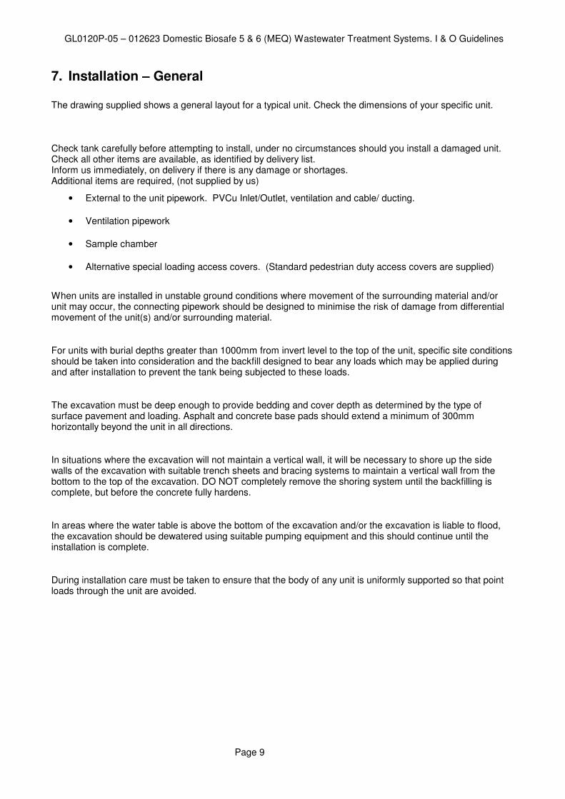
7. Installation – General
The drawing supplied shows a general layout for a typical unit. Check the dimensions of your specific unit. Check tank carefully before attempting to install, under no circumstances should you install a damaged unit. Check all other items are available, as identified by delivery list. Inform us immediately, on delivery if there is any damage or shortages. Additional items are required, (not supplied by us)
• External to the unit pipework. PVCu Inlet/Outlet, ventilation and cable/ ducting.
• Ventilation pipework
• Sample chamber
• Alternative special loading access covers. (Standard pedestrian duty access covers are supplied)
When units are installed in unstable ground conditions where movement of the surrounding material and/or unit may occur, the connecting pipework should be designed to minimise the risk of damage from differential movement of the unit(s) and/or surrounding material.
For units with burial depths greater than 1000mm from invert level to the top of the unit, specific site conditions should be taken into consideration and the backfill designed to bear any loads which may be applied during and after installation to prevent the tank being subjected to these loads.
The excavation must be deep enough to provide bedding and cover depth as determined by the type of surface pavement and loading. Asphalt and concrete base pads should extend a minimum of 300mm horizontally beyond the unit in all directions.
In situations where the excavation will not maintain a vertical wall, it will be necessary to shore up the side walls of the excavation with suitable trench sheets and bracing systems to maintain a vertical wall from the bottom to the top of the excavation. DO NOT completely remove the shoring system until the backfilling is complete, but before the concrete fully hardens.
In areas where the water table is above the bottom of the excavation and/or the excavation is liable to flood, the excavation should be dewatered using suitable pumping equipment and this should continue until the installation is complete.
During installation care must be taken to ensure that the body of any unit is uniformly supported so that point loads through the unit are avoided.

GL0120P-05 – 012623 Domestic Biosafe 5 & 6 (MEQ) Wastewater Treatment Systems. I & O Guidelines
Page 10
8. Concrete Specification
The concrete Specification below is a general specification. It is not a site specific installation design.
GENERAL CONCRETE SPECIFICATION IN ACCORDANCE WITH BS EN 206-1 ( BS 8500-1)
TYPE OF MIX (DC) DESIGN
PERMITTED TYPE OF CEMENT BS 12 (OPC): BS 12 (RHPC): BS 4027 (SRPC)
PERMITTED TYPE OF AGGREGATE (coarse & fine)
BS 882
NOMINAL MAXIMUM SIZE OF AGGREGATE 20 mm
GRADES: C25 /30
C25 /30
C16 /20
REINFORCED & ABOVE GROUND WITH HOLDING DOWN BOLTS
REINFORCED (EG. FOR HIGH WATER TABLE)
UNREINFORCED (NORMAL CONDITIONS)
MINIMUM CEMENT CONTENT
C30
C20
270 - 280 Kg/M3
220 - 230 Kg/M3
SLUMP CLASS S1 (25mm)
RATE OF SAMPLING READY MIX CONCRETE SHOULD BE SUPPLIED COMPLETE WITH APPROPRIATE DELIVERY TICKET IN ACCORDANCE WITH BS EN 12350-1
NOTE: STANDARD MIXES SHOULD NOT BE USED WHERE SULPHATES OR OTHER AGGRESSIVE CHEMICALS EXIST IN GROUND WATER
9. Unit Installation
Do not install in trafficked areas unless a suitable top slab has been designed and constructed. The top slab should bear on a suitable foundation to prevent superimposed loads being transmitted to the unit and access turrets. Loads applied must bear on the top slab, not the access turrets.
See the section on “Deep Invert Units” for fitting of extension necks and manifolds.
Ground conditions and water table level should be assessed. If the water table will be above the base of the unit at any time of the year, adequate concrete backfill must be provided to avoid flotation. In poorly draining ground, consideration should also be given to the likelihood of flotation due to surface water collecting in the backfill. It should be borne in mind that the inlet drain trench will act as a land drain, directing surface water to the backfill around the unit.
1. Excavate a hole of sufficient length and width to accommodate the tank plus a minimum 225mm concrete surround. The depth should allow for the burial depth of the unit plus a concrete base slab of 300mm. The maximum depth to the base of the excavation must be no more than 3.7m including the base slab.
2. Construct a suitable concrete base slab appropriate to site conditions. Ensure that the slab is flat and level.
3. When the concrete base slab has set enough to support the installed load, lower the unit onto the slab using suitable webbing slings and lifting equipment. The selection of lifting equipment is the responsibility of the installer considering unit weight, length, height and distance of lift. The unit includes baffles, pumps, diffusers and other components so please note that the unit weight will not be evenly balanced. Note the fitted feet are for stabilising purposes only.

GL0120P-05 – 012623 Domestic Biosafe 5 & 6 (MEQ) Wastewater Treatment Systems. I & O Guidelines
Page 11
4. Pour no more than 300mm depth of clean water into each compartment. This should be achieved simultaneously but avoid a shock load. A recommended way of doing this is to add clean water into the second biological treatment zone (which has media within it) until the level in the first biological treatment zone is 300mm. At the same time, fill the first and last turret, the primary and final settlement zones.
5. DO NOT OVERFILL; the unit is not designed to hold water whilst unsupported. Place concrete backfill to approximately 300mm depth under and to the sides of the tank ensuring good compaction to remove voids. Concrete backfill must be manually compacted; WE DO NOT recommend the use of vibrating lances. ALLOW INITIAL CONCRETE SET TO OCCUR BEFORE PROCEEDING. Ensure concrete fills the voids underneath tank and feet.
6. Continue adding concrete backfill, simultaneously keeping the internal water level no more than 300mm above the backfill level at all times, until the backfill is just below the underside of the outlet drain, giving sufficient room to connect the inlet and outlet pipework.
7. Connect the inlet and outlet drains to the site pipe work when safe access to the backfill can be gained.
8. Connect the ventilation pipes and run the pipe work to above ground level when safe access to the backfill can be gained.
9. Connect the cable conduits when safe access to the backfill can be gained.
10. Connect the two hoses to the internal diffuser assemblies via the pre drilled holes in the 2 centre necks of
the tank; connect to the internal galvanized manifold at the top of the air diffuser assemblies, secure in place with relevant jubilee clips.
11. Run the lengths of hose through the ducting to the blower housing, cut hose to required length and connect
the free ends to the outlet connections on the Blower Manifold securing in place with relevant jubilee clips.
12. Run the pre fitted control panel flying lead (15m) with ‘quick connector’ from the internal terminal box (JB001 situated in neck of Biozone 1) through the cable conduits to the main control panel and connect opposite end of quick connector.
13. Continue backfilling with concrete over the tank body to the required level. Build up a shell of concrete, minimum 225mm thick, around the access turrets.
Deep Invert Units The standard units include fitted access turrets, however, for units with deeper inverts i.e. 1500 mm inlet inverts and above, additional access turret sections need to be site fitted. Before fitting the extension turrets, you must fit the extension pipes to the diffuser droppers and couple to the manifold which must be fitted into the top extension. The pumps are also supplied with extension kits that must be fitted prior to installing the neck extension. The pump cable should also be brought to the uppermost turret as installation progresses.
When the installation includes a separate structural concrete raft it is necessary to order the extension kit to the full invert depth. The full invert depth is from finished ground level, Failure to take account of the finished ground level will mean that the internal valves and junction boxes will not be accessible for routine maintenance and servicing. This may require “confined space” entry which will significantly increase the cost of maintenance and servicing.

GL0120P-05 – 012623 Domestic Biosafe 5 & 6 (MEQ) Wastewater Treatment Systems. I & O Guidelines
Page 12
NB: For units with inverts greater than 1500mm the wiring loom junction boxes will NOT be supplied fixed to the neck, once the extension turrets have been fitted the junction boxes should be fixed to the upper most extension pieces in holes provided.
The additional turrets are flanged. Use the mastic supplied and bolt through the flanges, from top to bottom using washers below the bolt head and above the nut. Check that the flanges are fully sealed and water tight before completing the concrete backfill around each turret.
For deeper invert units (above 1000mm invert) we recommend that you temporarily strut extension turrets during this procedure to avoid distortion or collapse as the necks are non-structural.
Continue back-filling in 300mm stages, ensuring minimum 225mm concrete thickness around the access turrets.
Leave until the concrete is fully cured. The unit should be left filled with clean water up to the invert level of the outlet pipe. Check that there is a discharge.
Replace all manhole covers.
Electrical connection Electrical work should be carried out by only by a qualified electrician working to the latest electrical regulations.
The treatment unit contains the following electrical components inside the plant, all of which are prewired to a common electrical terminal (JB001) located within one of the middle turrets:
• High Level Float
• Recirculation Pump
• Desludge Pump The main supply blower and control panel are located in the GRP housing supplied with unit. Connecting Main Blower: Run cable between the blower terminal box and the Control Panel connecting the cable to the blower terminals within the control panel (see wiring diagram supplied with unit). Connecting Internal Loom: Run the cable with quick connector (male end) from JB001 through the ducting to the Control panel kiosk. Connect the male quick connector to the female quick connector located on the base of the control panel. Connect the control panel to the suitably protected mains power supply. The wiring is complete. Please insure you refer to the wiring diagrams provided in the control panel.

GL0120P-05 – 012623 Domestic Biosafe 5 & 6 (MEQ) Wastewater Treatment Systems. I & O Guidelines
Page 13
10. Technical Information
Model Biosafe 5 Biosafe 6
Max flow m
3/
day 8 11
Peak flow rate for ½ hr in any 2 hour period
m3/
hr 0.9 1.25
Main Blower power / Power supply phase Full load current
Kw
A
0.27 230 V Single
10.5
0.27 230 V Single
11.8 Recirculation Pumps (on timer operation) Power Power supply phase Full load current
Kw
A
0.25
230 V single 1.9
11. Process
General
The biological treatment process of your unit is self-regulating and it requires no specialised operational knowledge, but it is important that you are aware of the following points.
Your system uses colonies of live natural micro-organisms (biomass), to break down the pollutants in the sewage. Many chemicals used in households and commercial establishments can inhibit or kill these micro-organisms; particularly if used in excessive amounts.
Generally speaking all common household cleaning fluids are acceptable, provided they are used in accordance with the makers’ instructions and stipulated concentrations. The golden rule is "If in doubt - leave it out”. Commercial cleansing products are much stronger and some can adversely affect the biology." Please see the list of Do’s and Don’ts.
Standard Effluent quality
This system process is designed to achieve a high quality effluent from a domestic sewage feed.
When loaded at is maximum rated capacity (BOD and Ammonia, the plant design provides for a 90 days desludge interval.
Operation
The biological process requires the addition of power and air. Blowers, pumps, air lifts and diffusers are used to control the process; movement /recycling of liquids and solids and provide oxygen for the biological process. Within the unit there are aerobic zones, controlling aerobic biological treatment, nitrification and de-nitrification. The process energy efficiency is optimised as a result of utilising biological de-nitrification and high efficiency air diffusers.
The air supply is provided from a blower mounted remotely from the plant adjacent to the electrical control panel. Duty / Standby units or Duty / Assist configurations are available options.

GL0120P-05 – 012623 Domestic Biosafe 5 & 6 (MEQ) Wastewater Treatment Systems. I & O Guidelines
Page 14
The unit is divided into a number of compartments. At the front of the unit is a large compartment, the purpose of which is to provide a settlement zone for the primary solids.
From the primary compartment, the settled effluent passes into an aerated carbonaceous treatment biozone. This compartment contains diffusers and media. The carbonaceous biozone is followed by a large aerated nitrification biozone also with diffusers and media. Within these zones bacteria grow both on the surface of media and suspended within the liquor. The system is able to adapt quickly to a change in sewage loading and the bacterial biomasses will develop to cope with the normal daily load variations.
The system can be adjusted to perform with reduced loads (i.e. down to 50% of the specified maximum daily load) When it has been identified /agreed that this facility is required, the design modifications will have been completed pre delivery. The modifications can be made post installation to accommodate this requirement. (Site inspection charges will apply) This makes the Biosafe particularly useful for applications which expect to have periods of inactivity, such as schools, or when the loads are of a seasonal nature.
The final compartment acts as the final settlement tank (FST) where the fine solids settle. Effluent discharges by gravity, overflowing from the system into a sample chamber. (Optional Extra)
Within each compartment, the volume and liquid levels are controlled using a mixture of air lift transfers and pumped recycling. There is minimal hydraulic loss across the unit, (150mm fall). The plant design incorporates flow management to smooth out the volume and load variations and create the optimum conditions for bacterial growth.
In a gravity feed situation, in the event of a power failure, the sewage will flow into the plant, be primary settled and pass through the various zones before overflowing into the final settlement tank and out of the discharge pipe.
The system requires regular desludging from the primary and final compartments only. There is no need or requirement to empty either of the biozones. The biozones stay in operation during the period following servicing whilst the water level is restored. As a result of this, the final effluent quality remains consistently good.
Users should be made aware that their sewage enters a biological wastewater treatment system so that they can dispose of their waste considerately. Not everything is suitable for disposal into the system, for example where the unit serves premises with a catering function, special arrangements should be made to prevent the oils, fats and grease from entering the unit. Disinfectants, weed-killers, medicines, brewers cleansing chemicals etc. can all adversely affect the biological process. Please request User leaflets which provides detailed information for individual householders.

GL0120P-05 – 012623 Domestic Biosafe 5 & 6 (MEQ) Wastewater Treatment Systems. I & O Guidelines
Page 15
Domestic and other properties feeding into the system should display a label within the building identifying use of a treatment system. See introduction notes. We can supply copies of the labels for use at individual properties.
Specified effluent qualities
The design will be tailored for each application to suit the expected daily incoming volume, the advised influent level and the required effluent quality. This information is provided separately or within the electrical panel settings.
Timer Settings
Electrical drawings for the timer setting are in the control panel
Model Biosafe 5 Biosafe 6
Cycle length hour 1 1
De-sludge timer on seconds 38 51
Desludge timer off minutes 59 59
Cycle length hour 0.25 0.25
Recycle timer on minutes 0.7 0.9
Recycle timer off minutes 14 14
Do’s and Don’ts – Domestic Products
Washing machine and dishwasher detergents, washing up liquids:
These are generally all right to use in the normal concentrations and usage found in domestic housing applications but when chemical dosing, they should be chosen with care to avoid un-necessary addition of phosphate. All commercial applications should be individually assessed before installation for their laundry load. Please contact us for advice if any changes are contemplated e.g. addition of extra laundry facilities.
Floor cleaners, disinfectants and bleaches:
These are safe to use in accordance with the makers recommendations and in the minimum necessary quantity and concentration. Do not pour neat disinfectant or bleach down sinks or outside gullies. If these are smelly it usually indicates a build up of decaying material, fat or a plumbing problem and should be dealt with accordingly.
Nappy disinfectants and bottle sterilising fluids. e.g. Milton:
When disposing of the used fluid, ensure that it is well diluted with water. The easiest way of doing this is usually to flush it away down the toilet.
Waste disposal units:
These should not be used. Their use has not been considered when designing the process. They do not inhibit the biomass, but, depending on their use, they can present the treatment plant with considerable extra load and solids. This can result in the treatment process becoming unbalanced, leading to problems. It is much better to compost vegetable peelings etc - its cheaper and environmentally friendly.
Home beer and wine making.
This presents a similar problem to waste disposal units. The unit has to work as hard to treat one pint of beer tipped down the drain as it does to treat all the normal waste produced by one person in 24 hours. See also the notes above regarding sterilising fluids.

GL0120P-05 – 012623 Domestic Biosafe 5 & 6 (MEQ) Wastewater Treatment Systems. I & O Guidelines
Page 16
THE FOLLOWING MUST NOT BE DISCHARGED INTO THE DRAINS (This is not an exhaustive list!):
• Cooking oil and fat.
• Chemical Toilet Waste
• Motor oil, grease, anti-freeze, brake fluid etc.
• Weed-killers, insecticides, fungicides and other gardening chemicals.
• Paint, thinners, white spirit, turpentine, creosote etc.
• Medicines -Take unused medicines to a pharmacist for safe disposal.
• Photographic developing fluids and chemicals.
• Strong commercial cleansing chemicals, e.g., products for cleaning beer lines, drain products.
• Nappies, nappy liners, sanitary items, fabric wipes, rags, soft toys, tennis balls etc
o Although such items are not directly damaging to the biomass they can cause problems, not the least of which is simple blockage of the drains. Even so-called disposable nappies and sanitary towels often do not degrade fully in the treatment plant and can lead to malfunction, so it is best to dispose of them by other means.
12. Operation
General Every care is taken to ensure that all mechanical components are correctly fitted and adjusted prior to leaving the factory. However, subsequent handling during transportation and installation may result in the movement of components and an alteration of valve settings causing a need to re-adjust prior to starting the unit. If, on inspection, you consider that any components require adjustment, please contact us. We consider that it is essential that these units are properly commissioned by us before use.
After installation, the unit should have been left full of clean water. Power should be connected to the control panel, pumps, unit and any ancillary equipment.
Power should be left OFF, pending our inspection. Please contact us to arrange Pre-service Inspection Agreement
Should you choose to start up the system without using our services, the following notes are provided for assistance however, in providing these, we have assumed that your contractor has correctly installed, connected and tested all the equipment correctly.
Optional Pump Station Check that the pumps have been installed and wired to the Pump Control Panel.
Check that the Pump Control Panel timer is set correctly. Our pump stations are usually supplied with a separate control panel, but in some instances, we may supply a single control panel to operate the treatment system and pump station)
Check the setting of the floats in the pump chamber.
Ensure that the float(s) can operate freely without risk of entanglement.
Influent pumps should be set to pump little and often in order to spread the load entering the treatment unit. Direct pumping into the unit should be avoided by using an external upstream discharge point. (Please consult us for further parameters)
Treatment Unit
Check that the unit is full of water to the outlet level.
GL0120P-05 – 012623 Domestic Biosafe 5 & 6 (MEQ) Wastewater Treatment Systems. I & O Guidelines
Page 17
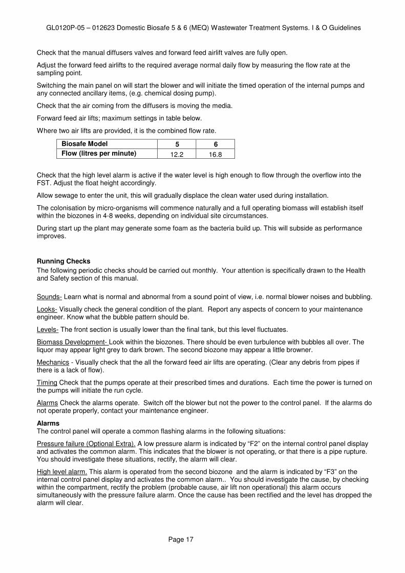
Check that the manual diffusers valves and forward feed airlift valves are fully open.
Adjust the forward feed airlifts to the required average normal daily flow by measuring the flow rate at the sampling point.
Switching the main panel on will start the blower and will initiate the timed operation of the internal pumps and any connected ancillary items, (e.g. chemical dosing pump).
Check that the air coming from the diffusers is moving the media.
Forward feed air lifts; maximum settings in table below.
Where two air lifts are provided, it is the combined flow rate.
Biosafe Model 5 6
Flow (litres per minute) 12.2 16.8
Check that the high level alarm is active if the water level is high enough to flow through the overflow into the FST. Adjust the float height accordingly.
Allow sewage to enter the unit, this will gradually displace the clean water used during installation.
The colonisation by micro-organisms will commence naturally and a full operating biomass will establish itself within the biozones in 4-8 weeks, depending on individual site circumstances.
During start up the plant may generate some foam as the bacteria build up. This will subside as performance improves.
Running Checks
The following periodic checks should be carried out monthly. Your attention is specifically drawn to the Health and Safety section of this manual.
Sounds- Learn what is normal and abnormal from a sound point of view, i.e. normal blower noises and bubbling.
Looks- Visually check the general condition of the plant. Report any aspects of concern to your maintenance engineer. Know what the bubble pattern should be.
Levels- The front section is usually lower than the final tank, but this level fluctuates.
Biomass Development- Look within the biozones. There should be even turbulence with bubbles all over. The liquor may appear light grey to dark brown. The second biozone may appear a little browner.
Mechanics - Visually check that the all the forward feed air lifts are operating. (Clear any debris from pipes if there is a lack of flow).
Timing Check that the pumps operate at their prescribed times and durations. Each time the power is turned on the pumps will initiate the run cycle.
Alarms Check the alarms operate. Switch off the blower but not the power to the control panel. If the alarms do not operate properly, contact your maintenance engineer.
Alarms The control panel will operate a common flashing alarms in the following situations:
Pressure failure (Optional Extra). A low pressure alarm is indicated by “F2” on the internal control panel display and activates the common alarm. This indicates that the blower is not operating, or that there is a pipe rupture. You should investigate these situations, rectify, the alarm will clear.
High level alarm. This alarm is operated from the second biozone and the alarm is indicated by “F3” on the internal control panel display and activates the common alarm.. You should investigate the cause, by checking within the compartment, rectify the problem (probable cause, air lift non operational) this alarm occurs simultaneously with the pressure failure alarm. Once the cause has been rectified and the level has dropped the alarm will clear.

GL0120P-05 – 012623 Domestic Biosafe 5 & 6 (MEQ) Wastewater Treatment Systems. I & O Guidelines
Page 18
Power failure. This alarm is indicated by “F1” on the internal control panel display and activates the common alarm. It will automatically reset itself if the power supply returns. If it does not, within an appropriate period, investigate.
Note Any interruption of power supply will adversely affect the effluent quality.
13. Maintenance
General
The system operates with air blowers, pumps and airlifts.
• Blowers will require checking regularly and will require filter cleaning and replacement.
• Air lifts must be checked to ensure that they are performing correctly, delivering the correct volume and have not become blocked.
• Pumps are operated using timers. Periodically pumps will need to be removed and their orifices checked for blockages.
Desludging The system requires emptying periodically. When operating at the normal daily load, emptying should take place at 90 day intervals. The frequency of sludge removal is expected to increase if the unit is chemically dosed. The volumes to be removed from each unit are given in the table below. Units which are over utilised may require more frequent emptying. Units which are not emptied will accumulate excess solids within the compartments. Final solids will be released and contribute to poor effluent qualities, run the risk of blocking any associated drainage field and contribute to pollution. Different allowances/calculations should be made for non domestic inputs such as pubs and other commercial premises. Please contact us for an assessment. DO NOT EXTEND THE EMPTYING FREQUENCY Maintenance Contracts
We recommend and can provide regular planned maintenance visits to inspect the operation and performance of the units. Please contact us for details
Desludging Procedure
The two stage primary zone should be de-sludged to remove the floating scum and approximately 60% of the volume. The FST requires the floating surface sludge to removed along with 50% of its volume. See table below for volumes.
1. Isolate power at the main control panel. 2. Remove access covers from the first, second and last access points. 3. Remove the floating surface scum from the final settlement tank. (last access point). 4. Place desludging nozzle into the base of the tank and withdraw the volume indicated, taking the
settled sludge rather than the supernatant liquor. Note. Please avoid the location of the pump connected by fixed pipework from the base of the compartment.
5. Remove the floating surface scum from the first and then second compartments of the primary settlement zone (first and second access points)
6. Place desludging nozzle into the base of first compartment tank and withdraw 80% of the advised volume, taking the settled sludge rather than the supernatant liquor. Take any settled sludge from the base of the second compartment up to total volume indicated.
7. DO NOT REMOVE LIQUOR FROM ANY OF THE OTHER COMPARTMENTS. (THESE MUST NOT BE EMPTIED AS TO DO SO REMOVES BOTH THE BIOMASS AND THE MEDIA)

GL0120P-05 – 012623 Domestic Biosafe 5 & 6 (MEQ) Wastewater Treatment Systems. I & O Guidelines
Page 19
8. Replace all the access covers and secure. 9. Switch on power at the main control panel. 10. Allow sewage to enter the first compartment as normal, only if supplied by a pump station
Note. Level switches on the recycle pumps will prevent their operation until a satisfactory liquid level has been reached.
Biosafe Model Biosafe 5 Biosafe 6
FST plus scum layer litres gallons
3,900 1,030
5,300 1,400
PST plus scum layer litres gallons
8,800 2,325
11,500 3,040
Total Volume to be removed per visit
litres gallons
12,700 3,350
16,800 4,440
Note: A log should be kept recording the frequency of emptying. Note: The waste should be removed under the terms of The Waste Management Code of Practice. The Code imposes a duty of care on the waste producer to ensure that the Cleansing contractor is registered with the Environment Regulator and that the final disposal of the waste is to a licensed facility.
Servicing Our site engineers are available to carry out Pre-service Inspection Agreement, service and maintenance visits. We recommend regular maintenance contracts for these units. We offer a service to supervise tank emptying. Contact details are provided on the cover sheet.
14. Warranty
Taken from ‘Kingspan’s Terms & Conditions of Sale’ The company will replace or, at its option, properly repair without charge any goods which are found to be defective and which cause failure in normal circumstances of use within a period of twelve months from the date of delivery. This warranty is conditional upon: (a) the Buyer notifying the Company of any claim within Seven days of the failure becoming discernible. (b) the Company being allowed a reasonable opportunity to inspect the goods so as to confirm that they are defective. (c) the goods not having been modified, mishandled or misused and being used strictly in accordance with any relevant instructions issued by the Company. The Company’s liability under this Clause is limited to the repair or replacement of the defective goods, and does not cover costs of transport, installation or associated site costs, if applicable. The Company’s liability to replace or repair the goods is in lieu of and excludes all other warranties and conditions, and in particular (but without limitation) the Company shall have no liability of any kind for consequential loss or damage. For any further advice, please contact us. A Warranty Form is included in this package, to register your unit for Warranty. Please complete ALL sections of the form, and return it at your earliest convenience.

GL0120P-05 – 012623 Domestic Biosafe 5 & 6 (MEQ) Wastewater Treatment Systems. I & O Guidelines
Page 20
Our service provider: Kingspan Environmental Services: 0845 355 05
15. FAQ’s
20 Frequently asked questions; if you do not find your answer please contact our technical team.
1. General.
• Maintenance and service checks should be carried out by suitably trained personnel.
• Electrical equipment should only be worked on by suitably skilled personnel.
2. Can I get into the tank to fix something • On no account should anybody enter the tank.
3. Is it safe to work on the plant
• If suitable safety precautions are observed.
• Always wear rubber/latex gloves.
• Safely isolate the electricity supply to the plant
• Always wash thoroughly after contact with the plant.
• Do not eat/drink or smoke without washing hands first.
• Any splashes into the eye should be rinsed with saline water SEEK MEDICAL ADVICE.
• If any liquid in the plant is swallowed, do nor induce vomiting, drink plenty of water, seek medical attention.
4. Something has fallen into the tank
• Do not attempt to enter the tank.
• If the item floats, use a fishing net or similar tool to remove.
• If it sinks and it is magnetic, tie a strong magnet to a rope and attempt to remove it.
• In the majority of cases small items are not a problem, but check the diffusers for damage particulary if vigorous “boiling” is evident.
5. There is foam oozing out of the vent/access covers+
• This is normal on start up of this type of biological process.
• It will subside in a few days depending on the connected load on the plant.
• Water spray will knock it down or small doses of silicon based anti foam may be used.
6. There is a dry crust on the surface of the primary tank
• This is quite normal and will not cause any problems.
• When the tank is “de-sludged”, this crust will be removed.
7. There is a dark brown wet sludge on the surface of the final settlement zone
• This is a good indication that the process is operating, but may also indicate a problem with the sludge return pump.
• Isolate the power to the plant, remove the pump and check operation.
8. A noise like vigorous boiling water is coming from one of the access points.
• The diffuser may have come off the drop pipe.
9. The plant is smelling like raw sewage, slightly sickly sweet
• Check that the air blower is operating, check the inlet air filter on the blower, if blocked fit a clean one.
• Check the liquid level in the plant, is there a blockage downstream causing the liquid to back

GL0120P-05 – 012623 Domestic Biosafe 5 & 6 (MEQ) Wastewater Treatment Systems. I & O Guidelines
Page 21
up? (Particularly Soak-aways and drainage mounds).
• Check for indications of toxic chemicals such as disinfection, drain cleaning products or caustic based cleaners etc.
10. There is a white growth in the water course where the plant discharge is
• A sign of poor treatment. The biological process is overloaded, the blower is under performing, Toxic chemicals, disinfectants, cleaners etc
11. The water discharging from the plant has a rainbow sheen on it
• Petroleum products, oil or diesel have been discharge into the plant. Locate source and eliminate.
• The plant will recover from small discharges but a large discharge may require a special tanker, contact your local licensed waste disposal company.
12. The blower discharge pipe is very hot.
• If the blower is too hot, check the air filter, if there is a large resistance to removing the cover, the filter is blocked, replace.
• Check that the valves on the aeration drop pipes are open.
• Check the water level in the tank: high level the blower works harder so temperature high.
• The blower will normally be 25°C to 30°C higher than the outside air temperature.
• Are the ventilation louvers in kiosk clear, run with the kiosk door open for 10-15 minutes, does the blower cool down? If yes, increase the ventilation into the kiosk.
• Are there any signs of the blower pipe work being damaged or crushed?
13. The final effluent is cloudy
• This usually occurs when the plant de-sludge is overdue.
• Check service records and arrange de-sludge.
• Other causes are “process” related and normal checks should be made on the blower, toxic chemicals and un-authorised discharges.
14. The final effluent is coloured • This can be: unauthorised discharges, or ground
water entering the plant
15. What position should the ball valves in the diffuser pipes be?
• Valve position is determined by airflow so all plants may vary.
• Position valves so media is agitated but not moving violently.
16. Will the air diffusers need cleaning. • Not in normal operation.
• Flow of air will unblock diffusers.
17. My warning beacon is flashing. • Check control panel for fault (see table below).
Control Panel Fault Indication Codes
Code Fault
F1 Mains Failure
F2 Blower Pressure Not Present (If Fitted)
F3 High Level Alarm/Main Blower Not Running
F4 Timer Circuit Fuse Fault (Fuse F3 - 3.15A HBC)

GL0120P-05 – 012623 Domestic Biosafe 5 & 6 (MEQ) Wastewater Treatment Systems. I & O Guidelines
Page 22
Notice to affix within the building
BIOSAFE
The foul drainage from this property discharges into a package treatment works. Maintenance is required, the frequency of which depends upon the model installed, its use and application. Please consult your Operation & Maintenance Manual.
* When operating at the normal daily load, emptying should take place at 90 day intervals.
* The frequency of sludge removal is expected to increase if the unit is chemically dosed and require more frequent maintenance (see individual operating manuals)
Maintenance and Desludging should be carried out by the owner in accordance with the Manufactures instructions.
THE OWNER OF THE PROPERTY IS LEGALLY RESPONSIBLE FOR ENSURING THAT THE SYSTEM DOES NOT CAUSE POLLUTION, A HEALTH HAZARD OR A NUISANCE.
We recommend that a separate log is kept of all maintenance and service visits, the log should detail the date and any action taken, e.g. Regular maintenance service, breakdown visit, desludge volume removed, parts replaced. This notice should be fixed by the owner within the building alerting current and future owners to the maintenance requirement.
(Building regulation H2 (1.57) Please contact Service on +44 (0) 844 846 0500 or Service Department Ireland on + 44 (0) 2830254077 to arrange a maintenance service or to request replacement operating instructions. It would be helpful if you provide your equipment serial number.