Embed Size (px)
Citation preview


2
Section 1 - Introduction . . . . . . . . . . . . . . . . . 1-31.1 The Manual . . . . . . . . . . . . . . . . . . . . . . . 1-31.2 Service and Replacement Parts . . . . . . . 1-31.3 Product Registration . . . . . . . . . . . . . . . . 1-31.4 Unauthorized Replacement Parts . . . . . . 1-31.5 Disclaimer . . . . . . . . . . . . . . . . . . . . . . . . 1-31.6 Technical Service Communications . . . . . 1-3
Section 2 - Safety2.1 Safety Alerts . . . . . . . . . . . . . . . . . . . . . . 2-42.2 Signal Words . . . . . . . . . . . . . . . . . . . . . . 2-42.3 Notations . . . . . . . . . . . . . . . . . . . . . . . . . 2-42.4 Practices and Laws . . . . . . . . . . . . . . . . . 2-42.5 Required Operator Training . . . . . . . . . . . 2-42.6 Preparation . . . . . . . . . . . . . . . . . . . . . . . 2-42.7 Cleaning and Storage . . . . . . . . . . . . . . . 2-42.8 Safety Rules . . . . . . . . . . . . . . . . . . . . . . 2-5
Section 3 - Specifications . . . . . . . . . . . . . . . 3-8
Section 4 - General Maintenance &Adjustments. . . . . . . . . . . . . . . . . . . . . . . .4-21
4.1 Controls and Features . . . . . . . . . . . . . . .4-214.2 Service Positions . . . . . . . . . . . . . . . . . . .4-224.3 Filling The Fuel Tank . . . . . . . . . . . . . . . .4-224.4 General Lubrication . . . . . . . . . . . . . . . . .4-224.5 Check Mower Blade. . . . . . . . . . . . . . . . .4-234.6 Check Drive Belt . . . . . . . . . . . . . . . . . . .4-234.7 Check Engine/Blade Control . . . . . . . . . .4-234.8 Check Grass Bag. . . . . . . . . . . . . . . . . . .4-244.9 Check Drive Control. . . . . . . . . . . . . . . . .4-244.10 Handlebar Adjustment . . . . . . . . . . . . . .4-254.11 Speed Control Bell Crank. . . . . . . . . . . .4-254.12 Friction Wheel Adjustment. . . . . . . . . . .4-26
Section 5 - Engine . . . . . . . . . . . . . . . . . . . . . .5-275.1 Engine Troubleshooting . . . . . . . . . . . . . .5-275.2 Engine Service Locations . . . . . . . . . . . .5-285.3 Engine Oil . . . . . . . . . . . . . . . . . . . . . . . .5-295.4 Air Cleaner . . . . . . . . . . . . . . . . . . . . . . . .5-295.5 Engine Cooling. . . . . . . . . . . . . . . . . . . . .5-315.6 Spark Plug . . . . . . . . . . . . . . . . . . . . . . . .5-315.7 Battery (Electric Start Model) . . . . . . . . . .5-31
Section 6 - Mower Deck . . . . . . . . . . . . . . . . .6-326.1 Blade Brake/clutch Removal . . . . . . . . . .6-326.2 Drive Belt Replacement . . . . . . . . . . . . . .6-336.3 Idler Removal. . . . . . . . . . . . . . . . . . . . . .6-336.4 Wheels And Adjusters . . . . . . . . . . . . . . .6-33
Section 7 - Handlebars & Controls . . . . . . . .7-377.1 Handlebars And Bails . . . . . . . . . . . . . . .7-377.2 Speed Control Bell Crank . . . . . . . . . . . .7-37
Section 8 - Electrical . . . . . . . . . . . . . . . . . . . .8-398.1 Battery (Electric Start Models) . . . . . . . . .8-398.2 Wiring Diagram . . . . . . . . . . . . . . . . . . . .8-398.3 Continuity Diagram . . . . . . . . . . . . . . . . .8-39
Section 9 - Friction Drive System & Axle. . .9-409.1 Introduction . . . . . . . . . . . . . . . . . . . . . . .9-409.2 Gear Removal . . . . . . . . . . . . . . . . . . . . .9-409.3 Axle Removal. . . . . . . . . . . . . . . . . . . . . .9-409.4 Drive Mount Removal . . . . . . . . . . . . . . .9-409.5 Drive Mount Disassembly . . . . . . . . . . . .9-409.6 Friction Wheel Replacement . . . . . . . . . .9-409.7 Drive Disk Removal . . . . . . . . . . . . . . . . .9-41
Section 10 - Gear Drive System & Axle. . . . 10-4310.1 Introduction . . . . . . . . . . . . . . . . . . . . . 10-4310.2 Transmission Replacement . . . . . . . . . 10-43
TABLE OF CONTENTS
1 - 3
1.1 THE MANUALBefore operation of unit, carefully and completely read your manuals. The contents will provide you with an understanding of safety instructions and controls during normal operation and maintenance.
All reference to left, right, front, or rear are given from the operation position, facing the direction of forward travel.
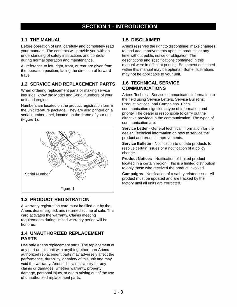
1.2 SERVICE AND REPLACEMENT PARTSWhen ordering replacement parts or making service inquiries, know the Model and Serial numbers of your unit and engine.
Numbers are located on the product registration form in the unit literature package. They are also printed on a serial number label, located on the frame of your unit (Figure 1).
1.3 PRODUCT REGISTRATIONA warranty registration card must be filled out by the Ariens dealer, signed, and returned at time of sale. This card activates the warranty. Claims meeting requirements during limited warranty period will be honored.
1.4 UNAUTHORIZED REPLACEMENT PARTSUse only Ariens replacement parts. The replacement of any part on this unit with anything other than Ariens authorized replacement parts may adversely affect the performance, durability, or safety of this unit and may void the warranty. Ariens disclaims liability for any claims or damages, whether warranty, property damage, personal injury, or death arising out of the use of unauthorized replacement parts.
1.5 DISCLAIMERAriens reserves the right to discontinue, make changes to, and add improvements upon its products at any time without public notice or obligation. The descriptions and specifications contained in this manual were in effect at printing. Equipment described within this manual may be optional. Some illustrations may not be applicable to your unit.
1.6 TECHNICAL SERVICE COMMUNICATIONSAriens Technical Service communicates information to the field using Service Letters, Service Bulletins, Product Notices, and Campaigns. Each communication signifies a type of information and priority. The dealer is responsible to carry out the directive provided in the communication. The types of communication are:
Service Letter - General technical information for the dealer. Technical information on how to service the product and product improvements.
Service Bulletin - Notification to update products to resolve certain issues or a notification of a policy change.
Product Notices - Notification of limited product located in a certain region. This is a limited distribution to only those who received the product involved.
Campaigns - Notification of a safety related issue. All product must be updated and are tracked by the factory until all units are corrected.
SECTION 1 - INTRODUCTION
Figure 1
Serial Number
2 - 4
2.1 SAFETY ALERTSLook for these symbols to point out important safety precautions. They mean:
Attention! Personal Safety Is Involved!Become Alert! Obey The Message!
2.2 SIGNAL WORDSThe safety alert symbol is used in decals on the unit and with proper operation procedures in this manual. They alert you to the existence and relative degree of hazards.
Understand the safety message. It contains important information about personal safety on or near the unit.
2.3 NOTATIONSNOTE: General reference information for proper oper-ation and maintenance practices.
IMPORTANT: Specific procedures or information required to prevent damage to unit or attachment.
2.4 PRACTICES AND LAWSPractice usual and customary safe working precautions, for the benefit of yourself and others. Understand and follow all safety messages. Be alert to unsafe conditions and the possibility of minor, moderate, or serious injury or death. Learn applicable rules and laws in your area.
2.5 REQUIRED OPERATOR TRAININGOriginal purchaser of this unit was instructed by the seller on safe and proper operation. If unit is to be used by someone other than original purchaser; loaned, rented or sold, ALWAYS provide this manual and any needed safety training before operation.
2.6 PREPARATIONBefore starting any removal of parts, proper preparation is very important for efficient work. A clean work area at the start of each job will allow you to perform service repairs easily and quickly.
To reduce the incidence of misplaced tools or parts, place removed components with all attaching hardware in the disassembly order on a clean work surface. Organization is a key part of proper reassembly.
Tools, instruments, and parts needed for the job should be gathered before work is started. Interrupting a job to locate tools or parts is a needless delay.
2.7 CLEANING AND STORAGE
IMPORTANT: Never spray unit with water or store unit outdoors to help prevent sealed bearing rust or corrosion. Water can seep into sealed bearings and reduce component life. Bearings are sealed against dirt and debris only.
A unit that is excessively dirty should be cleaned before work starts. Cleaning will occasionally uncover trouble sources. Dirt and abrasive dust reduce the efficient work life of parts and can lead to costly replacement.
SECTION 2 - SAFETY
DANGER: IMMINENTLY HAZARDOUS SITUATION! If not avoided, WILL RESULT in death or serious injury.
WARNING: POTENTIALLY HAZARDOUS SITUATION! If not avoided, COULD RESULT in death or serious injury.
CAUTION: POTENTIALLY HAZARDOUS SITUATION! If not avoided, MAY RESULT in minor or moderate injury. It may also be used to alert against unsafe practices.
CAUTION: Remove enough fuel so that no spillage will occur. Remove battery to prevent spillage of electrolyte.
WARNING: AVOID SHARP EDGES which can cut. Movement of parts can cut off fingers or a hand. Wear gloves, and use extreme caution when servicing.
2 - 5
When taking unit out of extended storage:
1. Check for any damage or loose parts. Repair, replace, or tighten hardware before operation.
2. If a preservative fluid was used in fuel tank, drain and discard. Fill fuel tank with fresh new fuel.
2.8 SAFETY RULES
Walk Around InspectionComplete a walk around inspection of unit and work area to understand:
• Work area.
• Your unit.
• All safety decals.
Work AreaALWAYS check overhead and side clearances carefully before operation. ALWAYS be aware of traffic when operating along streets or curbs.
ALWAYS keep hands and feet within the limits of the unit.
Keep children, people, and animals away. Keep children out of work area and under watchful care of a responsible adult.
Keep area of operation clear of all toys, pets, and debris. Stay alert for hidden hazards.
Clear work area of objects which might be picked up and thrown. Remove all stones, sticks, wires, and other foreign objects. Tall grass can hide obstacles.
DO NOT run engine in an enclosed area. Always provide good ventilation.
UnitALWAYS keep protective structures, guards, and panels in good repair, in place and securely fastened. NEVER modify or remove safety devices.
Check Safety Interlock System for proper operation daily (see Operation section). Do not operate unless system operates properly.
Keep equipment in good condition.
ALWAYS keep discharge cover in place.
NEVER operate the engine with the Rear Door open unless the Grass Bag is in place.
When mulching, the Side Discharge Opening Cover must be installed and the Rear Door fully closed whenever the engine is operating.
OperationUnderstand:
• How to operate all controls
• The functions of all controls
• How to STOP in an Emergency
• Speed ranges
ALWAYS operate unit in good visibility and light.
DO NOT pull mower backwards unless absolutely necessary. Look down and back before and while moving backwards.
DO NOT start the engine or operate mower unless either the Side Discharge Opening Cover or the Side Discharge Deflector is installed.
Keep the area of operation clear of all persons, children and pets.
ALWAYS clear area before operation to avoid thrown objects.
Stop mower if anyone enters the area.
Keep safety devices or guards in place and functioning properly. NEVER modify or remove safety devices.
ALWAYS keep hands away from all rotating parts during operation.
Do not put hands or feet near or under rotating parts. Keep clear of the discharge opening and mower pan at all times. NEVER open the Rear Door without the Grass Bag in place when the engine is operating.
ALWAYS keep feet and hands away from all rotating parts during operation. Rotating parts can cut off body parts.
DO NOT mow at too fast a rate. DO NOT change engine governor setting or over-speed the engine.
ALWAYS operate unit when there is good visibility and light.
Use extra care when approaching blind corners, shrubs, trees, or other objects which may obscure vision.
ALWAYS be sure of your footing.
Do not operate mower in wet grass. Always be sure of your footing. Keep a firm hold on handlebar. Walk, never run.
If equipment vibrates abnormally, stop engine at once, wait for moving parts to stop and remove wire from spark plug. Repair any damage before restarting unit.
Avoid uneven work areas and any rough terrain.
Be familiar with area of operation. Stay alert for holes, rocks, roots, and hidden hazards in area of operation. Operator could lose footing or balance.
DO NOT operate on steep slopes.
NEVER leave unit unattended on a slope. Chock wheels if parking on a slope.
Mow across the face of slopes, never up and down. Be especially cautious when changing direction on slopes.
Remove the key when parking.
Take all possible precautions when leaving unit unattended.
ALWAYS shut off engine, remove key and remove spark plug wire to prevent accidental starting or unauthorized use.

2 - 6
Fuel is highly flammable and its vapors can explode. Use ONLY approved fuel containers. NO Smoking!NO Sparks!NO Flames!Allow engine to cool before servicing.NEVER fill fuel tank when engine is running, hot, or unit is indoors.
Abnormal Vibrations are a warning of trouble. Striking a foreign object can damage unit. Stop unit and engine. Wait for all moving parts to stop. Remove wire from spark plug. Inspect unit and make any necessary repairs before restart.
Hazardous SlopesDO NOT operate on steep slopes. Avoid operating on slopes. When you must operate on a slope, travel up and down the slope. Never operate cross a slope. Never operate on a slope greater than 10 degrees.
Child SafetyNEVER allow children to operate or play on or near unit. Be alert and shut off unit if children enter area.
Personal SafetyRead and obey all warning, caution, and instructions on the unit and in provided manuals.
• Only trained adults may operate unit.
• Training includes actual operation.
• Clearly understand instructions.
• Be alert! Conditions can change.
NEVER operate unit after or during the use of medication, drugs or alcohol. Safe operation requires your complete and unimpaired attention at all times.
NEVER allow anyone to operate the unit when their alertness or coordination is impaired.
Avoid Sharp Edges. Sharp edges can cut. Moving parts can cut or amputate fingers or a hand. Wear gloves to service unit when handling sharp edges.
ALWAYS keep hands away from any pinch points.
ALWAYS keep hands and feet away from all moving parts during operation. Moving parts can cut off body parts.
DO NOT touch unit parts which might be hot from operation. Allow parts to cool before attempting to maintain, adjust, or service.
Keep children out of work area and under the watchful care of an adult.
NEVER allow children to operate mower.
Turn the mower off if children enter the area.
NEVER direct discharge toward bystanders. The operator is responsible for the safety of bystanders.
Wear adequate safety gear, protective gloves and footwear.
Wear sturdy footwear. DO NOT operate mower barefoot or when wearing open sandals or canvas shoes.
Always wear safety goggles or safety glasses with side shields when operating mower.
NEVER wear loose clothing, jewelry or long hair that may get caught in rotating parts. Protect eyes, face and head from objects that may be thrown from unit.
ALWAYS stand clear of discharge when operating unit.
Do not operate mower on gravel or on loose material such as sand. Stop mower when crossing gravel drives, walks, or roads, Objects may be picked up and thrown, causing damage or injury.
Fumes from the engine exhaust can cause death or serious injury. DO NOT run engine in an enclosed area.
Service and AdjustmentsNEVER attempt to make any adjustments to unit while engine is running. Stop engine, remove key, disconnect spark plug wire and wait for all moving parts to stop before servicing (except where specifically recommended).
DO NOT make cutting height wheel adjustments while the engine is running.
On self-propelled models, the wheel drive control will cause the forward movement of the mower to stop. If this feature fails to operate, disconnect ignition wire and repair before using. Wheel drive must be disengaged when starting engine.
Fuel is highly flammable and its vapors can explode. ONLY use approved fuel containers.
• NO Smoking!
• NO Sparks!
• NO Flames!
• Allow engine to cool before filling fuel tank.
Check fuel supply before starting engine.
DO NOT fill gasoline tank indoors, when engine is running, or while engine is still hot.
Allow engine to cool several minutes before removing fuel cap.
Replace gasoline tank cap securely and clean up any spilled fuel before starting engine.
Stop engine, wait for moving parts to stop, remove ignition wire and secure away from spark plug before attempting to: unclog, repair, adjust, inspect or clean unit.
To reduce fire hazard and overheating, keep equipment free of grass, leaves, debris or excessive lubricants.
2 - 7
BatteryAvoid Electric Shock. DO NOT remove wire from spark plug while engine is running. Do not put battery in fire or mutilate.
Explosive Gases! Poisonous battery fluid contains sulfuric acid. Contact with skin, eyes or clothing can cause severe chemical burns.
No flames, No Sparks, No smoking, near battery.
ALWAYS wear safety glasses and protective gear near battery.
ALWAYS KEEP BATTERIES OUT OF REACH of children.
MaintenanceFollow engine manufacturer’s safety instructions when servicing engine.
Keep all nuts, bolts, and screws tight and be sure equipment is in safe working condition. Check all hardware at regular intervals, especially blade attachment bolts.
Use only replacement parts designed for your unit. See your Ariens Dealer.
Worn out mufflers are more than just a noise nuisance and should be replaced immediately. Continued use could result in fire or explosion.
ALWAYS block wheels and know all jack stands are strong and secure and will hold weight of unit during maintenance.
Check grass bag for wear, damage, and/or deterioration. Replace only with Ariens original equipment replacement part for safety.
StorageAllow engine to cool before storing in any enclosure.
Refer to Storage Section of the Owner’s Manual for important instructions if unit is to be stored for extended periods.
ALWAYS clean unit before extended storage. See engine manual for proper storage.
DO NOT store unit before extended storage. See engine manual for proper storage.
DO NOT store unit inside a building with fuel in the fuel tank where ignition sources are present.
Safety Interlock SystemEngine/Blade Control feature on mower will cause engine and blade to stop whenever operator releases control on handlebar. If feature fails to operate, disconnect spark plug wire and adjust or have it repaired before using unit.
AccessoriesUse only accessories which have been approved by Ariens and are properly installed.
Spark ArrestorThis product is equipped with an internal combustion engine. DO NOT use on or near any unimproved, forest or brush covered land unless the exhaust system is equipped with a spark arrestor meeting applicable local, state or federal laws. A spark arrestor, if used, must be maintained in effective working order by the operator. See your Ariens Dealer or engine manufacturer’s service center.

3 - 8
SECTION 3 - SPECIFICATIONS
Model Number 911044 911045 911046 911047
Description Name LM214SP LM219SP LM217SP LM21SB
Engine Manufacture Tecumseh Briggs Tecumseh Tecumseh
Cycles Four Four Four Four
HP (3600RPM) 5.5 5 5.5 5.5
Fuel Tank Capacity - qt (L) 1.5 (1.4) 1.6 (1.5) 1.5 (1.4) 1.5 (1.4)
Fuel Unleaded Unleaded Unleaded Unleaded
Primer Bulb Standard Standard Standard Standard
Throttle/Choke Control N/A N/A N/A N/A
Starting Recoil Recoil Recoil Recoil
Cylinder Bore Aluminum Aluminum Aluminum Aluminum
Pressurized Oil System Standard N/A Standard N/A
Governed RPM 2850+/-150 2900 2850+/-150 2900
Crank Case Capacity - oz (L) 27 (0.8) 20 (0.6) 27 (0.8) 27 (0.8)
Air Cleaner Paper Element Paper Element Paper Element Paper Element
Engine Oil Type SAE 30 SAE 30 SAE 30 SAE 30
Spark Plug Gap 0.03 0.03 0.03 0.03
Differential Standard Standard Standard Standard
Variable Speeds-MPH (KPH) 0-3.5 (0-5.6) 0-3.5 (0-5.6) 0-3.5 (0-5.6) 0-3.5 (0-5.6)
Mower Deck Gauge 14 Gauge Stamped Steel
14 Gauge Stamped Steel
14 Gauge Stamped Steel
14 Gauge Stamped Steel
Baked Powder Paint Standard Standard Standard Standard
Cutting Width - in (cm) 21 (53.3) 21 (53.3) 21 (53.3) 21 (53.3)
Cutting Height - in (cm) 6 Positions 6 Positions 6 Positions 6 Positions
1.2-3.5 (3.2-8.9) 1.2-3.5 (3.2-8.9) 1.2-3.5 (3.2-8.9) 1.2-3.5 (3.2-8.9)
Folding Handlebar Standard One Piece Standard One Piece Standard One Piece Standard One Piece
Adjustable Handlebar 4 Position 4 Position 4 Position 4 Position
Front Wheel Diameter - in (cm) 7.5 (19.1) 7.5 (19.1) 7.5 (19.1) 7.5 (19.1)
Rear Wheel Diameter - in (cm) 10.5 (26.7) 10.5 (26.7) 10.5 (26.7) 10.5 (26.7)
Side Discharge Standard Standard Standard Standard
Bagger Standard Standard Standard Standard
Mulching Capability With Kit With Kit With Kit With Kit
Attachments (* denotes it comes with unit)
Dethatcher 71102400 71102400 71102400 71102400
Mulchmaster Package 71102700 71102700 71102700 71102700
Leaf Shredder 71102800 71102800 71102800 71102800
Side Discharge Chute 71102900 71102900 71102900 71102900
Rear Bagger 71103000 71103000 71103000 71103000
Swivel Wheel Kit 71103300 71103300 71103300 71103300
Rear Discharge Chute 71103200 71103200 71103200 71103200
Rear Roller Kit 71103400 71103400 71103400 71103400
Mulching Kit 71103500 71103500 71103500 71103500

3 - 9
Model Number 911048 911049 911050 911051
Description Name LM21SC LM21 LM21S LM21
Engine Manufacture Briggs Tecumseh Tecumseh Tecumseh
Cycles Four Four Four Four
HP (3600RPM) 5 5 5 5.5
Fuel Tank Capacity - qt (L) 1.6 (1.5) 1 (0.9) 1 (0.9) 1.5 (1.4)
Fuel Unleaded Unleaded Unleaded Unleaded
Primer Bulb Standard Standard Standard Standard
Throttle/Choke Control
Starting Recoil Recoil Recoil Recoil
Cylinder Bore Cast Iron Sleeve Aluminum Aluminum Aluminum
Pressurized Oil System N/A N/A N/A N/A
Governed RPM 2850 2850 2850 2850
Crank Case Capacity - oz (L) 20 (0.6) 21 (0.6) 21 (0.6) 27 (0.8)
Air Cleaner Dual Element Paper Element Paper Element Paper Element
Engine Oil Type SAE 30 SAE 30 SAE 30 SAE 30
Spark Plug Gap 0.03 0.03 0.03 0.03
Differential Standard N/A Standard N/A
Variable Speeds-MPH (KPH) 0-3.5 (0-5.6) N/A 0-3.5 (0-5.6) N/A
Mower Deck Gauge 14 Gauge Stamped Steel
14 Gauge Stamped Steel
14 Gauge Stamped Steel
14 Gauge Stamped Steel
Baked Powder Paint Standard Standard Standard Standard
Cutting Width - in (cm) 21 (53.3) 21 (53.3) 21 (53.3) 21 (53.3)
Cutting Height - in (cm) 6 Positions 6 Positions 6 Positions 6 Positions
1.2-3.5 (3.2-8.9) 1.2-3.5 (3.2-8.9) 1.2-3.5 (3.2-8.9) 1.2-3.5 (3.2-8.9)
Folding Handlebar Standard One Piece Standard One Piece Standard One Piece Standard One Piece
Adjustable Handlebar 4 Position 4 Position 4 Position 4 Position
Front Wheel Diameter - in (cm) 7.5 (19.1) 7.5 (19.1) 7.5 (19.1) 7.5 (19.1)
Rear Wheel Diameter - in (cm) 10.5 (26.7) 10.5 (26.7) 10.5 (26.7) 10.5 (26.7)
Side Discharge Standard Standard Standard Standard
Bagger Standard Standard Standard Standard
Mulching Capability With Kit With Kit With Kit With Kit
Attachments (* denotes it comes with unit)
Dethatcher 71102400 71102400 71102400 N/A
Mulchmaster Package 71102700 71102700 71102700 71102700
Leaf Shredder 71102800 71102800 71102800 71102800
Side Discharge Chute 71102900 71102900 71102900 71102900
Rear Bagger 71103000 71103000 71103000
Swivel Wheel Kit 71103300 71103300 71103300 71103300
Rear Discharge Chute 71103200 71103200 71103200 71103200
Rear Roller Kit 71103400 71103400 71103400 71103400
Mulching Kit 71103500 71103500 71103500 71103500
3 - 10
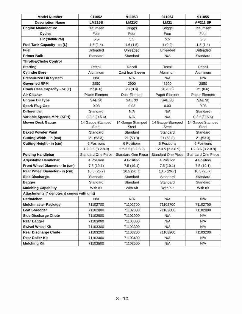
Model Number 911052 911053 911054 911055
Description Name LM216S LM21C LM21 AP211 SP
Engine Manufacture Tecumseh Briggs Briggs Tecumseh
Cycles Four Four Four Four
HP (3600RPM) 5.5 5.5 5.5 5.5
Fuel Tank Capacity - qt (L) 1.5 (1.4) 1.6 (1.5) 1 (0.9) 1.5 (1.4)
Fuel Unleaded Unleaded Unleaded Unleaded
Primer Bulb Standard Standard N/A Standard
Throttle/Choke Control
Starting Recoil Recoil Recoil Recoil
Cylinder Bore Aluminum Cast Iron Sleeve Aluminum Aluminum
Pressurized Oil System N/A N/A N/A N/A
Governed RPM 2850 2900 3200 2850
Crank Case Capacity - oz (L) 27 (0.8) 20 (0.6) 20 (0.6) 21 (0.6)
Air Cleaner Paper Element Dual Element Paper Element Paper Element
Engine Oil Type SAE 30 SAE 30 SAE 30 SAE 30
Spark Plug Gap 0.03 0.03 0.03 0.03
Differential Standard N/A N/A Standard
Variable Speeds-MPH (KPH) 0-3.5 (0-5.6) N/A N/A 0-3.5 (0-5.6)
Mower Deck Gauge 14 Gauge Stamped Steel
14 Gauge Stamped Steel
14 Gauge Stamped Steel
14 Gauge Stamped Steel
Baked Powder Paint Standard Standard Standard Standard
Cutting Width - in (cm) 21 (53.3) 21 (53.3) 21 (53.3) 21 (53.3)
Cutting Height - in (cm) 6 Positions 6 Positions 6 Positions 6 Positions
1.2-3.5 (3.2-8.9) 1.2-3.5 (3.2-8.9) 1.2-3.5 (3.2-8.9) 1.2-3.5 (3.2-8.9)
Folding Handlebar Standard One Piece Standard One Piece Standard One Piece Standard One Piece
Adjustable Handlebar 4 Position 4 Position 4 Position 4 Position
Front Wheel Diameter - in (cm) 7.5 (19.1) 7.5 (19.1) 7.5 (19.1) 7.5 (19.1)
Rear Wheel Diameter - in (cm) 10.5 (26.7) 10.5 (26.7) 10.5 (26.7) 10.5 (26.7)
Side Discharge Standard Standard Standard Standard
Bagger Standard Standard Standard Standard
Mulching Capability With Kit With Kit With Kit With Kit
Attachments (* denotes it comes with unit)
Dethatcher N/A N/A N/A N/A
Mulchmaster Package 71102700 71102700 71102700 71102700
Leaf Shredder 71102800 71102800 71102800 71102800
Side Discharge Chute 71102900 71102900 N/A N/A
Rear Bagger 71103000 71103000 N/A N/A
Swivel Wheel Kit 71103300 71103300 N/A N/A
Rear Discharge Chute 71103200 71103200 71103200 71103200
Rear Roller Kit 71103400 71103400 N/A N/A
Mulching Kit 71103500 71103500 N/A N/A

3 - 11
Model Number 911056 911057 911058 911059
Description Name AP212 SP LM2178 SP AP 210 LM220 SP
Engine Manufacture Tecumseh Briggs Tecumseh Tecumseh
Cycles Four Four Four Four
HP (3600RPM) 4.5 5 4 5.5
Fuel Tank Capacity - qt (L) 1.5 (1.4) 1.6 (1.5) 1.5 (1.4) 1.5 (1.4)
Fuel Unleaded Unleaded Unleaded Unleaded
Primer Bulb Standard Standard Standard Standard
Throttle/Choke Control
Starting Recoil Recoil Recoil Recoil
Cylinder Bore Aluminum Cast Iron Sleeve Aluminum Cast Iron Sleeve
Pressurized Oil System N/A N/A N/A N/A
Governed RPM 2850 2900 3200 2850
Crank Case Capacity - oz (L) 21 (0.6) 20 (0.6) 21 (0.6) 27 (0.8)
Air Cleaner Paper Element Dual Element Paper Element Dual Element
Engine Oil Type SAE 30 SAE 30 SAE 30 SAE 30
Spark Plug Gap 0.03 0.03 0.03 0.03
Differential Standard Standard N/A Standard
Variable Speeds-MPH (KPH) 0-3.5 (0-5.6) 0-3.5 (0-5.6) N/A 0-3.5 (0-5.6)
Mower Deck Gauge 14 Gauge Stamped Steel
14 Gauge Stamped Steel
14 Gauge Stamped Steel
14 Gauge Stamped Steel
Baked Powder Paint Standard Standard Standard Standard
Cutting Width - in (cm) 21 (53.3) 21 (53.3) 21 (53.3) 21 (53.3)
Cutting Height - in (cm) 6 Positions 6 Positions 6 Positions 6 Positions
1.2-3.5 (3.2-8.9) 1.2-3.5 (3.2-8.9) 1.2-3.5 (3.2-8.9) 1.2-3.5 (3.2-8.9)
Folding Handlebar Standard One Piece Standard One Piece Standard One Piece Standard One Piece
Adjustable Handlebar 4 Position 4 Position 4 Position 4 Position
Front Wheel Diameter - in (cm) 7.5 (19.1) 7.5 (19.1) 7.5 (19.1) 7.5 (19.1)
Rear Wheel Diameter - in (cm) 10.5 (26.7) 10.5 (26.7) 10.5 (26.7) 10.5 (26.7)
Side Discharge Standard Standard Standard Standard
Bagger Standard Standard Standard Standard
Mulching Capability With Kit With Kit With Kit With Kit
Attachments (* denotes it comes with unit)
Dethatcher N/A N/A N/A 71102400
Mulchmaster Package 71102700 71102700 71102700 71102700
Leaf Shredder 71102800 N/A 71102800 71102800
Side Discharge Chute N/A 71102900 N/A 71102900
Rear Bagger N/A N/A N/A 71103000
Swivel Wheel Kit N/A 71103300 N/A 71103300
Rear Discharge Chute 71103200 71103200 71103200 71103200
Rear Roller Kit N/A 71103400 N/A 71103400
Mulching Kit N/A 71103500 N/A 71103500
3 - 12
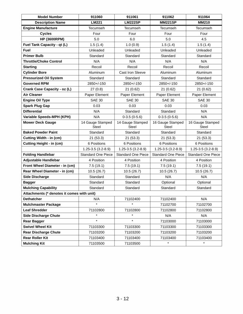
Model Number 911060 911061 911062 911064
Description Name LM221 LM222SP MM221SP MM210
Engine Manufacture Tecumseh Tecumseh Tecumseh Tecumseh
Cycles Four Four Four Four
HP (3600RPM) 5.0 6.0 5.0 4.5
Fuel Tank Capacity - qt (L) 1.5 (1.4) 1.0 (0.9) 1.5 (1.4) 1.5 (1.4)
Fuel Unleaded Unleaded Unleaded Unleaded
Primer Bulb Standard Standard Standard Standard
Throttle/Choke Control N/A N/A N/A N/A
Starting Recoil Recoil Recoil Recoil
Cylinder Bore Aluminum Cast Iron Sleeve Aluminum Aluminum
Pressurized Oil System Standard Standard Standard Standard
Governed RPM 2850+/-150 2850+/-150 2850+/-150 2850+/-150
Crank Case Capacity - oz (L) 27 (0.8) 21 (0.62) 21 (0.62) 21 (0.62)
Air Cleaner Paper Element Paper Element Paper Element Paper Element
Engine Oil Type SAE 30 SAE 30 SAE 30 SAE 30
Spark Plug Gap 0.03 0.03 0.03 0.03
Differential N/A Standard Standard N/A
Variable Speeds-MPH (KPH) N/A 0-3.5 (0-5.6) 0-3.5 (0-5.6) N/A
Mower Deck Gauge 14 Gauge Stamped Steel
14 Gauge Stamped Steel
16 Gauge Stamped Steel
16 Gauge Stamped Steel
Baked Powder Paint Standard Standard Standard Standard
Cutting Width - in (cm) 21 (53.3) 21 (53.3) 21 (53.3) 21 (53.3)
Cutting Height - in (cm) 6 Positions 6 Positions 6 Positions 6 Positions
1.25-3.5 (3.2-8.9) 1.25-3.5 (3.2-8.9) 1.25-3.5 (3.2-8.9) 1.25-3.5 (3.2-8.9)
Folding Handlebar Standard One Piece Standard One Piece Standard One Piece Standard One Piece
Adjustable Handlebar 4 Position 4 Position 4 Position 4 Position
Front Wheel Diameter - in (cm) 7.5 (19.1) 7.5 (19.1) 7.5 (19.1) 7.5 (19.1)
Rear Wheel Diameter - in (cm) 10.5 (26.7) 10.5 (26.7) 10.5 (26.7) 10.5 (26.7)
Side Discharge Standard Standard N/A N/A
Bagger Standard Standard Optional Optional
Mulching Capability Standard Standard Standard Standard
Attachments (* denotes it comes with unit)
Dethatcher N/A 71102400 71102400 N/A
Mulchmaster Package * * 71102700 71102700
Leaf Shredder 71102800 71102800 71102800 71102800
Side Discharge Chute * * N/A N/A
Rear Bagger * * 71103000 71103000
Swivel Wheel Kit 71103300 71103300 71103300 71103300
Rear Discharge Chute 71103200 71103200 71103200 71103200
Rear Roller Kit 71103400 71103400 71103400 71103400
Mulching Kit 71103500 71103500 * *
3 - 13
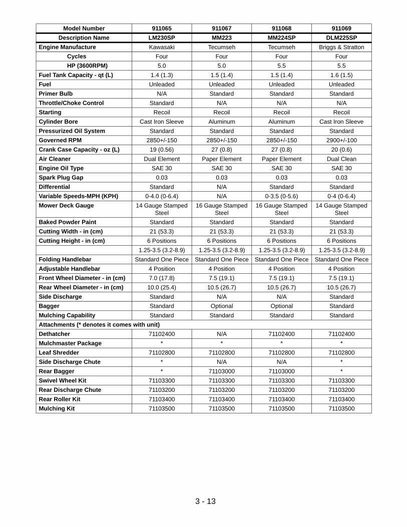
Model Number 911065 911067 911068 911069
Description Name LM230SP MM223 MM224SP DLM225SP
Engine Manufacture Kawasaki Tecumseh Tecumseh Briggs & Stratton
Cycles Four Four Four Four
HP (3600RPM) 5.0 5.0 5.5 5.5
Fuel Tank Capacity - qt (L) 1.4 (1.3) 1.5 (1.4) 1.5 (1.4) 1.6 (1.5)
Fuel Unleaded Unleaded Unleaded Unleaded
Primer Bulb N/A Standard Standard Standard
Throttle/Choke Control Standard N/A N/A N/A
Starting Recoil Recoil Recoil Recoil
Cylinder Bore Cast Iron Sleeve Aluminum Aluminum Cast Iron Sleeve
Pressurized Oil System Standard Standard Standard Standard
Governed RPM 2850+/-150 2850+/-150 2850+/-150 2900+/-100
Crank Case Capacity - oz (L) 19 (0.56) 27 (0.8) 27 (0.8) 20 (0.6)
Air Cleaner Dual Element Paper Element Paper Element Dual Clean
Engine Oil Type SAE 30 SAE 30 SAE 30 SAE 30
Spark Plug Gap 0.03 0.03 0.03 0.03
Differential Standard N/A Standard Standard
Variable Speeds-MPH (KPH) 0-4.0 (0-6.4) N/A 0-3.5 (0-5.6) 0-4 (0-6.4)
Mower Deck Gauge 14 Gauge Stamped Steel
16 Gauge Stamped Steel
16 Gauge Stamped Steel
14 Gauge Stamped Steel
Baked Powder Paint Standard Standard Standard Standard
Cutting Width - in (cm) 21 (53.3) 21 (53.3) 21 (53.3) 21 (53.3)
Cutting Height - in (cm) 6 Positions 6 Positions 6 Positions 6 Positions
1.25-3.5 (3.2-8.9) 1.25-3.5 (3.2-8.9) 1.25-3.5 (3.2-8.9) 1.25-3.5 (3.2-8.9)
Folding Handlebar Standard One Piece Standard One Piece Standard One Piece Standard One Piece
Adjustable Handlebar 4 Position 4 Position 4 Position 4 Position
Front Wheel Diameter - in (cm) 7.0 (17.8) 7.5 (19.1) 7.5 (19.1) 7.5 (19.1)
Rear Wheel Diameter - in (cm) 10.0 (25.4) 10.5 (26.7) 10.5 (26.7) 10.5 (26.7)
Side Discharge Standard N/A N/A Standard
Bagger Standard Optional Optional Standard
Mulching Capability Standard Standard Standard Standard
Attachments (* denotes it comes with unit)
Dethatcher 71102400 N/A 71102400 71102400
Mulchmaster Package * * * *
Leaf Shredder 71102800 71102800 71102800 71102800
Side Discharge Chute * N/A N/A *
Rear Bagger * 71103000 71103000 *
Swivel Wheel Kit 71103300 71103300 71103300 71103300
Rear Discharge Chute 71103200 71103200 71103200 71103200
Rear Roller Kit 71103400 71103400 71103400 71103400
Mulching Kit 71103500 71103500 71103500 71103500
3 - 14
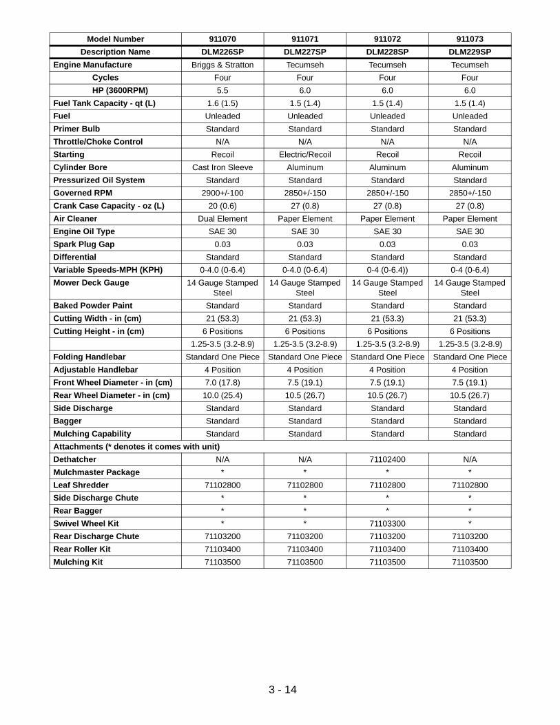
Model Number 911070 911071 911072 911073
Description Name DLM226SP DLM227SP DLM228SP DLM229SP
Engine Manufacture Briggs & Stratton Tecumseh Tecumseh Tecumseh
Cycles Four Four Four Four
HP (3600RPM) 5.5 6.0 6.0 6.0
Fuel Tank Capacity - qt (L) 1.6 (1.5) 1.5 (1.4) 1.5 (1.4) 1.5 (1.4)
Fuel Unleaded Unleaded Unleaded Unleaded
Primer Bulb Standard Standard Standard Standard
Throttle/Choke Control N/A N/A N/A N/A
Starting Recoil Electric/Recoil Recoil Recoil
Cylinder Bore Cast Iron Sleeve Aluminum Aluminum Aluminum
Pressurized Oil System Standard Standard Standard Standard
Governed RPM 2900+/-100 2850+/-150 2850+/-150 2850+/-150
Crank Case Capacity - oz (L) 20 (0.6) 27 (0.8) 27 (0.8) 27 (0.8)
Air Cleaner Dual Element Paper Element Paper Element Paper Element
Engine Oil Type SAE 30 SAE 30 SAE 30 SAE 30
Spark Plug Gap 0.03 0.03 0.03 0.03
Differential Standard Standard Standard Standard
Variable Speeds-MPH (KPH) 0-4.0 (0-6.4) 0-4.0 (0-6.4) 0-4 (0-6.4)) 0-4 (0-6.4)
Mower Deck Gauge 14 Gauge Stamped Steel
14 Gauge Stamped Steel
14 Gauge Stamped Steel
14 Gauge Stamped Steel
Baked Powder Paint Standard Standard Standard Standard
Cutting Width - in (cm) 21 (53.3) 21 (53.3) 21 (53.3) 21 (53.3)
Cutting Height - in (cm) 6 Positions 6 Positions 6 Positions 6 Positions
1.25-3.5 (3.2-8.9) 1.25-3.5 (3.2-8.9) 1.25-3.5 (3.2-8.9) 1.25-3.5 (3.2-8.9)
Folding Handlebar Standard One Piece Standard One Piece Standard One Piece Standard One Piece
Adjustable Handlebar 4 Position 4 Position 4 Position 4 Position
Front Wheel Diameter - in (cm) 7.0 (17.8) 7.5 (19.1) 7.5 (19.1) 7.5 (19.1)
Rear Wheel Diameter - in (cm) 10.0 (25.4) 10.5 (26.7) 10.5 (26.7) 10.5 (26.7)
Side Discharge Standard Standard Standard Standard
Bagger Standard Standard Standard Standard
Mulching Capability Standard Standard Standard Standard
Attachments (* denotes it comes with unit)
Dethatcher N/A N/A 71102400 N/A
Mulchmaster Package * * * *
Leaf Shredder 71102800 71102800 71102800 71102800
Side Discharge Chute * * * *
Rear Bagger * * * *
Swivel Wheel Kit * * 71103300 *
Rear Discharge Chute 71103200 71103200 71103200 71103200
Rear Roller Kit 71103400 71103400 71103400 71103400
Mulching Kit 71103500 71103500 71103500 71103500
3 - 15
Model Number 911075 911076 911077 911078
Description Name DLM21SEW DLM21SEW
Engine Manufacture Tecumseh Tecumseh Tecumseh Tecumseh
Cycles Four Four Four Four
HP (3600RPM) 6.0 5.5 5.5 6.0
Fuel Tank Capacity - qt (L) 1.5 (1.4) 1.5 (1.4) 1.5 (1.4) 1.5 (1.4)
Fuel Unleaded Unleaded Unleaded Unleaded
Primer Bulb Standard Standard Standard Standard
Throttle/Choke Control N/A N/A N/A N/A
Starting Electric/Recoil Recoil Electric/Recoil Electric/Recoil
Cylinder Bore Aluminum Aluminum Aluminum Aluminum
Pressurized Oil System Standard Standard Standard Standard
Governed RPM 2850+/-150 2850+/-150 2850+/-150 2850+/-150
Crank Case Capacity - oz (L) 27 (0.8) 27 (0.8) 27 (0.8) 27 (0.8)
Air Cleaner Paper Element Paper Element Paper Element Paper Element
Engine Oil Type SAE 30 SAE 30 SAE 30 SAE 30
Spark Plug Gap 0.03 0.03 0.03 0.03
Differential Standard Standard Standard Standard
Variable Speeds-MPH (KPH) 0-4 (0-6.4) 0-3.5 (0-5.6) 0-3.5 (0-5.6) 0-4 (0-6.4)
Mower Deck Gauge 14 Gauge Stamped Steel
14 Gauge Stamped Steel
14 Gauge Stamped Steel
14 Gauge Stamped Steel
Baked Powder Paint Standard Standard Standard Standard
Cutting Width - in (cm) 21 (53.3) 21 (53.3) 21 (53.3) 21 (53.3)
Cutting Height - in (cm) 6 Positions 6 Positions 6 Positions 6 Positions
1.25-3.5 (3.2-8.9) 1.25-3.5 (3.2-8.9) 1.25-3.5 (3.2-8.9) 1.25-3.5 (3.2-8.9)
Folding Handlebar Standard One Piece Standard One Piece Standard One Piece Standard One Piece
Adjustable Handlebar 4 Position 4 Position 4 Position 4 Position
Front Wheel Diameter - in (cm) 7.5 (19.1) 7.0 (17.8) 7.5 (19.1) 7.5 (19.1)
Rear Wheel Diameter - in (cm) 10.5 (26.7) 10.0 (25.4) 10.5 (26.7) 10.5 (26.7)
Side Discharge Standard Standard Standard Standard
Bagger Standard Standard Standard Standard
Mulching Capability Standard With Kit With Kit Standard
Attachments (* denotes it comes with unit)
Dethatcher N/A 71102400 71102400 N/A
Mulchmaster Package * 71102700 71102700 *
Leaf Shredder 71102800 71102800 71102800 71102800
Side Discharge Chute * 71102900 71102900 *
Rear Bagger * 71103000 71103000 *
Swivel Wheel Kit * 71103300 71103300 *
Rear Discharge Chute 71103200 71103200 71103200 71103200
Rear Roller Kit 71103400 71103400 71103400 71103400
Mulching Kit 71103500 71103500 71103500 71103500

3 - 16
Model Number 911079 911080 911081 911082
Description Name DLM21S DLM21SW SLM21 SLM21S
Engine Manufacture Tecumseh Tecumseh Tecumseh Tecumseh
Cycles Four Four Four Four
HP (3600RPM) 6.0 6.0 5.0 5.5
Fuel Tank Capacity - qt (L) 1.5 (1.4) 1.5 (1.4) 1.5 (1.4) 1.5 (1.4)
Fuel Unleaded Unleaded Unleaded Unleaded
Primer Bulb Standard Standard Standard Standard
Throttle/Choke Control N/A N/A N/A N/A
Starting Recoil Recoil Recoil Recoil
Cylinder Bore Aluminum Aluminum Aluminum Aluminum
Pressurized Oil System Standard Standard Standard Standard
Governed RPM 2800+/-200 2800+/-200 3150+/-200 3150+/-200
Crank Case Capacity - oz (L) 27 (0.8) 27 (0.8) 27 (0.8) 27 (0.8)
Air Cleaner Paper Element Paper Element Paper Element Paper Element
Engine Oil Type SAE 30 SAE 30 SAE 30 SAE 30
Spark Plug Gap 0.03 0.03 0.03 0.03
Differential Standard Standard N/A Standard
Variable Speeds-MPH (KPH) 0-4 (0-6.4) 0-4 (0-6.4) N/A 0-3.5 (0-5.6)
Mower Deck Gauge 14 Gauge Stamped Steel
14 Gauge Stamped Steel
16 Gauge Stamped Steel
16 Gauge Stamped Steel
Baked Powder Paint Standard Standard Standard Standard
Cutting Width - in (cm) 21 (53.3) 21 (53.3) 21 (53.3) 21 (53.3)
Cutting Height - in (cm) 6 Positions 6 Positions 6 Positions 6 Positions
1.25-3.5 (3.2-8.9) 1.25-3.5 (3.2-8.9) 1.25-3.5 (3.2-8.9) 1.25-3.5 (3.2-8.9)
Folding Handlebar Standard One Piece Standard One Piece Standard One Piece Standard One Piece
Adjustable Handlebar 4 Position 4 Position 4 Position 4 Position
Front Wheel Diameter - in (cm) 7.5 (19.1) 7.0 (17.8) 7.5 (19.1) 7.5 (19.1)
Rear Wheel Diameter - in (cm) 10.5 (26.7) 10.0 (25.4) 10.5 (26.7) 10.5 (26.7)
Side Discharge Standard Standard N/A N/A
Bagger Standard Standard Standard Standard
Mulching Capability Standard Standard Standard With Kit
Attachments (* denotes it comes with unit)
Dethatcher 71102400 N/A N/A 71102400
Mulchmaster Package * * * *
Leaf Shredder 71102800 71102800 71102800 71102800
Side Discharge Chute * * N/A N/A
Rear Bagger * * * *
Swivel Wheel Kit 71103300 * 71103300 71103300
Rear Discharge Chute 71103200 71103200 71103200 71103200
Rear Roller Kit 71103400 71103400 71103400 71103400
Mulching Kit 71103500 71103500 71103500 71103500
3 - 17
Model Number 911083 911084 911304 911311
Description Name DLM21C DLM21SC LM21 LM21S
Engine Manufacture Robin Robin Briggs & Stratton Briggs & Stratton
Cycles Four Four Four Four
HP (3600RPM) 6.0 6.0 5.0 5.0
Fuel Tank Capacity - qt (L) 1.5 (1.4) 1.5 (1.4) 1.5 (1.4) 1.5 (1.4)
Fuel Unleaded Unleaded Unleaded Unleaded
Primer Bulb N/A N/A N/A N/A
Throttle/Choke Control Standard Standard Standard Standard
Starting Recoil Recoil Recoil Recoil
Cylinder Bore Cast Iron Sleeve Cast Iron Sleeve Aluminum Aluminum
Pressurized Oil System Standard Standard Standard Standard
Governed RPM 2850+/-150 2850+/-150 2900+/-100 2900+/-100
Crank Case Capacity - oz (L) 17 (0.5) 17 (0.5) 20 (0.6) 20 (0.6)
Air Cleaner Dual Element Dual Element Paper Element Paper Element
Engine Oil Type SAE 30 SAE 30 SAE 30 SAE 30
Spark Plug Gap 0.03 0.03 0.03 0.03
Differential N/A Standard N/A Standard
Variable Speeds-MPH (KPH) N/A 0-4 (0-6.4) 0-4 (0-6.4) 0-4 (0-6.4)
Mower Deck Gauge 14 Gauge Stamped Steel
14 Gauge Stamped Steel
14 Gauge Stamped Steel
14 Gauge Stamped Steel
Baked Powder Paint Standard Standard Standard Standard
Cutting Width - in (cm) 21 (53.3) 21 (53.3) 21 (53.3) 21 (53.3)
Cutting Height - in (cm) 6 Positions 6 Positions 6 Positions 6 Positions
1.25-3.5 (3.2-8.9) 1.25-3.5 (3.2-8.9) 1.25-3.5 (3.2-8.9) 1.25-3.5 (3.2-8.9)
Folding Handlebar Standard One Piece Standard One Piece Standard One Piece Standard One Piece
Adjustable Handlebar 4 Position 4 Position 4 Position 4 Position
Front Wheel Diameter - in (cm) 7.0 (17.8) 7.0 (17.8) 7.5 (19.1) 7.5 (19.1)
Rear Wheel Diameter - in (cm) 10.0 (25.4) 10.0 (25.4) 10.5 (26.7) 10.5 (26.7)
Side Discharge Standard Standard Standard Standard
Bagger Standard Standard Standard Standard
Mulching Capability Standard Standard With Kit With Kit
Attachments (* denotes it comes with unit)
Dethatcher N/A 71102400 N/A 71102400
Mulchmaster Package * * 71102700 71102700
Leaf Shredder 71102800 71102800 71102800 71102800
Side Discharge Chute * * * *
Rear Bagger * * * *
Swivel Wheel Kit 71103300 71103300 71103300 71103300
Rear Discharge Chute 71103200 71103200 71103200 71103200
Rear Roller Kit 71103400 71103400 71103400 71103400
Mulching Kit 71103500 71103500 71103500 71103500
3 - 18
Model Number 911463 911467 911468 911469
Description Name DLM239 SLM237 SLM238SP DLM232SP
Engine Manufacture Robin Tecumseh Tecumseh Briggs & Stratton
Cycles Four Four Four Four
HP (3600RPM) 6.0 5.0 5.5 5.5
Fuel Tank Capacity - qt (L) 1.5 (1.4) 1.5 (1.4) 1.5 (1.4) 1.6 (1.5)
Fuel Unleaded Unleaded Unleaded Unleaded
Primer Bulb N/A Standard Standard Standard
Throttle/Choke Control Standard N/A N/A N/A
Starting Recoil Recoil Recoil Recoil
Cylinder Bore Cast Iron Sleeve Aluminum Aluminum Cast Iron Sleeve
Pressurized Oil System Standard Standard Standard Standard
Governed RPM 2900+/-100 3200+/-150 3200+/-150 2900+/-100
Crank Case Capacity - oz (L) 17 (0.5) 27 (0.8) 27 (0.8) 20 (0.6)
Air Cleaner Dual Element Paper Element Paper Element Dual Clean
Engine Oil Type SAE 30 SAE 30 SAE 30 SAE 30
Spark Plug Gap 0.03 0.03 0.03 0.03
Differential N/A N/A Standard Standard
Variable Speeds-MPH (KPH) N/A N/A 0-3.5 (0-5.6) 0-4 (0-6.4)
Mower Deck Gauge 14 Gauge Stamped Steel
16 Gauge Stamped Steel
16 Gauge Stamped Steel
14 Gauge Stamped Steel
Baked Powder Paint Standard Standard Standard Standard
Cutting Width - in (cm) 21 (53.3) 21 (53.3) 21 (53.3) 21 (53.3)
Cutting Height - in (cm) 6 Positions 6 Positions 6 Positions 6 Positions
1.25-3.5 (3.2-8.9) 1.25-3.5 (3.2-8.9) 1.25-3.5 (3.2-8.9) 1.25-3.5 (3.2-8.9)
Folding Handlebar Standard One Piece Standard One Piece Standard One Piece Standard One Piece
Adjustable Handlebar 4 Position 4 Position 4 Position 4 Position
Front Wheel Diameter - in (cm) 7.0 (17.8) 7.5 (19.1) 7.5 (19.1) 7.5 (19.1)
Rear Wheel Diameter - in (cm) 10.0 (25.4) 10.5 (26.7) 10.5 (26.7) 10.5 (26.7)
Side Discharge Standard N/A N/A Standard
Bagger Standard Standard Standard Standard
Mulching Capability Standard Standard Standard Standard
Attachments (* denotes it comes with unit)
Dethatcher N/A N/A 71102400 71102400
Mulchmaster Package * * * *
Leaf Shredder 71102800 71102800 71102800 71102800
Side Discharge Chute * N/A N/A *
Rear Bagger * * * *
Swivel Wheel Kit 71103300 71103300 71103300 71103300
Rear Discharge Chute 71103200 71103200 71103200 71103200
Rear Roller Kit 71103400 71103400 71103400 71103400
Mulching Kit 71103500 71103500 71103500 71103500

3 - 19
Model Number 911475 911509 911511 911513
Description Name DLM240SP LM21SCH LM21SC LM21
Engine Manufacture Robin Robin Robin Briggs & Stratton
Cycles Four Four Four Four
HP (3600RPM) 6.0 5.4 5.3 4.37
Fuel Tank Capacity - qt (L) 1.5 (1.4) 2.0 (1.9) 2 (1.9) 22 oz. (0.65)
Fuel Unleaded Unleaded Unleaded Unleaded
Primer Bulb N/A N/A N/A Standard
Throttle/Choke Control Standard Standard Standard N/A
Starting Recoil Recoil Recoil Recoil
Cylinder Bore Cast Iron Sleeve Aluminum Cast Iron Sleeve Aluminum
Pressurized Oil System Standard Splash Pressurized Splash
Governed RPM 2900+/-100 3000+/-100 3000+/-100 3000+/-100
Crank Case Capacity - oz (L) 27 (0.8) 17 (0.5) 17 (0.5) 22 (0.65)
Air Cleaner Dual Element Dual Element Dual Element Paper Element
Engine Oil Type SAE 30 SAE 30 SAE 30 SAE 30
Spark Plug Gap 0.03 0.03 0.03 0.03
Differential Standard Standard Standard N/A
Variable Speeds-MPH (KPH) 0-4 (0-6.4) 1.55, 2.98, 3.8 (2.48, 4.77, 6.08)
0-3.5 (0-5.6) N/A
Mower Deck Gauge 14 Gauge Stamped Steel
14 Gauge Stamped Steel
14 Gauge Stamped Steel
14 Gauge Stamped Steel
Baked Powder Paint Standard Standard Standard Standard
Cutting Width - in (cm) 21 (53.3) 21 (53.3) 21 (53.3) 21 (53.3)
Cutting Height - in (cm) 6 Positions 6 Positions 1.25-3.5 6 Positions 6 Positions
1.25-3.5 (3.2-8.9) 1-3.5 (3.2-8.9) 1.25-3.5 (3.2-8.9) 1.25-3.5 (3.2-8.9)
Folding Handlebar Standard One Piece Standard One Piece Standard One Piece Standard One Piece
Adjustable Handlebar 4 Position 4 Position 4 Position 4 Position
Front Wheel Diameter - in (cm) 7.0 (17.8) 8 (20.3) 7.5 (19.1) 7.5 (19.1)
Rear Wheel Diameter - in (cm) 10.0 (25.4) 8 (20.3) 10.5 (26.7) 10.5 (26.7)
Side Discharge Standard Standard Standard Standard
Bagger Standard Standard Standard Standard
Mulching Capability Standard Standard Standard Standard
Attachments (* denotes it comes with unit)
Dethatcher 71102400 71102400 71102400 71102400
Mulchmaster Package * 71102700 * *
Leaf Shredder 71102800 71103700 71102800 71102800
Side Discharge Chute * * * *
Rear Bagger * * * *
Swivel Wheel Kit 71103300 71104000 71103300 71103300
Rear Discharge Chute 71103200 71103200 71103200 71103200
Rear Roller Kit 71103400 71103400 71103400 71103400
Mulching Kit 71103500 71103500 71103500 71103500
3 - 20
Model Number 911514 911515 911516 911517
Description Name LM21S LM21SE LM21SW LM21SC
Engine Manufacture Briggs & Stratton Briggs & Stratton Briggs & Stratton Robin
Cycles Four Four Four Four
HP (3600RPM) 4.37 4.37 4.37 5.3
Fuel Tank Capacity - qt (L) 22 oz. (0.65) 22 oz (0.65) 22 oz (0.65) 2 (1.9)
Fuel Unleaded Unleaded Unleaded Unleaded
Primer Bulb Standard Standard Standard N/A
Throttle/Choke Control N/A N/A N/A Standard
Starting Recoil Electric/Recoil Recoil Recoil
Cylinder Bore Aluminum Aluminum Aluminum Cast Iron Sleeve
Pressurized Oil System Splash Splash Splash Pressurized
Governed RPM 3000+/-100 3000+/-100 3000+/-100 3000+/-100
Crank Case Capacity - oz (L) 22 (0.65) 22 (0.65) 22 (0.65) 17 (0.5)
Air Cleaner Paper Element Paper Element Paper Element Dual Element
Engine Oil Type SAE 30 SAE 30 SAE 30 SAE 30
Spark Plug Gap 0.03 0.03 0.03 0.03
Differential Standard Standard N/A Standard
Variable Speeds-MPH (KPH) 0-4 (0-6.4) 0-4 (0-6.4) N/A 0-3.5 (0-5.6)
Mower Deck Gauge 14 Gauge Stamped Steel
14 Gauge Stamped Steel
14 Gauge Stamped Steel
14 Gauge Stamped Steel
Baked Powder Paint Standard Standard Standard Standard
Cutting Width - in (cm) 21 (53.3) 21 (53.3) 21 (53.3) 21 (53.3)
Cutting Height - in (cm) 6 Positions 6 Positions 6 Positions 6 Positions
1.25-3.5 (3.2-8.9) 1.25-3.5 (3.2-8.9) 1.25-3.5 (3.2-8.9) 1.25-3.5 (3.2-8.9)
Folding Handlebar Standard One Piece Standard One Piece Standard One Piece Standard One Piece
Adjustable Handlebar 4 Position 4 Position 4 Position 4 Position
Front Wheel Diameter - in (cm) 7.5 (19.1) 7.0 (17.8) 7.5 (19.1) 7.5 (19.1)
Rear Wheel Diameter - in (cm) 10.5 (26.7) 10.0 (25.4) 10.5 (26.7) 10.5 (26.7)
Side Discharge Standard Standard Standard Standard
Bagger Standard Standard Standard Standard
Mulching Capability Standard Standard Standard Standard
Attachments (* denotes it comes with unit)
Dethatcher 71102400 71102400 N/A 71102400
Mulchmaster Package * * * 71102700
Leaf Shredder 71102800 71102800 71102800 71102800
Side Discharge Chute * * * *
Rear Bagger * * * *
Swivel Wheel Kit 71103300 71103300 * 71103300
Rear Discharge Chute 71103200 71103200 71103200 71103200
Rear Roller Kit 71103400 71103400 71103400 71103400
Mulching Kit 71103500 71103500 71103500 71103500
4 - 21
4.1 CONTROLS AND FEATURES
SECTION 4 - GENERAL MAINTENANCE & ADJUSTMENTS
OM0032
1. Engine Control2. Ignition Switch (Electric Start
Models)3. Speed Selector (Self-propelled)4. Primer (Briggs Engine)5. Side Discharge Cover6. Side Discharge Deflector
7. Cutting Height Levers (2 Rear Wheel Adjusters, 2 Front Wheel Adjusters
8. Rear Door9. Adjustable and Folding
Handlebars10.Grass Bag
11.Recoil12.Wheel Drive Control13.Mulchmaster™ Plug14.Throttle Control (Robin Engines)15.Handlebar Adjustment Holes16.Speed Indicator (Self-propelled)
Figure 2
1
2
3
4
56
7
8
9
10
11
12
13
14
15
16
7

4 - 22
4.2 SERVICE POSITIONSPlace unit on a flat level surface. ALWAYS stop engine. Assure unit is secure and will not tip over. Strap and clamp onto bench if needed.
A handlebar service position is provided for tipping the unit for cleaning and service (Figure 3). See Adjustments.
IMPORTANT: When tipping to service engine or unit, use the following service positions for the brand and type of engine on your mower:
Tecumseh & Robin Engines: Place handlebar into service position and tip machine to the rear.
Briggs & Stratton Intek Engines: Place handlebar into handlebar service position and tip the machine to the left, opposite the discharge opening.
Kawasaki: Place handlebar in service position and tip unit to right.
IMPORTANT: If engine becomes "flooded" due to tipping, clean air cleaner and remove spark plug, put one teaspoon of oil in cylinder, turn engine over a few times and reinstall spark plug.
4.3 FILLING THE FUEL TANK
To add fuel to fuel tank:
1. Put unit in open or well-ventilated area.
2. Stop engine and allow to cool.
3. Clean fuel cap and surrounding area to prevent dust, dirt and debris from entering fuel tank.
4. Remove cap.
IMPORTANT: DO NOT use gasohol or gasoline containing alcohol because alcohol will cause internal parts to deteriorate. See Engine Manual for correct type and grade of fuel.
5. Fill fuel tank. (See Specifications for tank capacity.)
6. Replace fuel cap and tighten.
7. ALWAYS clean up any spilled fuel.
4.4 GENERAL LUBRICATION
Swivel Lubrication (swivel units)
See Figure 4.
Apply Sten Mix Hi-Temp Grease or equivalent to the lube fittings. Order P/N: 00036800 - 3 pack of 3 oz. cartridges.
When using Sten Mix Grease for the first time, all components should be thoroughly cleaned prior to lubricating.
Commercial ModelsGrease fittings on rear axle housing every 25 hours.
WARNING: ACCIDENTAL ENGINE START UP can cause death or serious injury. ALWAYS stop engine, remove key, wait for moving parts to stop and remove wire from spark plug before adjusting or servicing.
CAUTION: FUEL SPILLS may result in minor or moderate injury and/or damage to the unit. Before unit is tipped up onto housing, remove enough fuel so that no spillage will occur. Remove battery to prevent spillage of electrolyte.
Figure 3OM0210
WARNING: EXPLOSIVE VAPORS and its FLAMMABLE FUEL can result in death or serious injury. Handle fuel with care.
ALWAYS use an approved fuel container.
No Smoking! No lighted Materials!
No Open Flame!
Allow engine to cool before maintenance. Gasoline is highly flammable and must be handled with care. Allow engine to cool several minutes before removing fuel tank cap. Never fill tank when engine is running or is hot from operation. DO NOT allow open flame, matches, or smoking in area. DO NOT overfill. Allow about 1/4" of tank space for fuel expansion. Wipe up any spills and allow vapors to dissipate before starting engine. Use approved gasoline container.

4 - 23
4.5 CHECK MOWER BLADE
See Figures 5 and 6.
Regularly check mower blades for wear and that lock washer is fully compressed by cap screw (requires 25-30 ft-lbs (33-40 Nm) of torque on cap screw).
When blade needs sharpening:
1. Block blade to prevent rotation.
2. Remove cap screw, lock washer and blade from shaft.
3. Sharpen both ends of blade at original angle (25
o
), removing equal amounts of material from each end to maintain proper blade balance. New blades are balanced to within 1.3 in. oz. at factory. DO NOT grind around corner at tip of blade. If cutting edge of blade cannot be sharpened in a straight line to within 1/8 of an inch of its end, replace blade with Ariens replacement blade only.
4. Install blade, lock washer and tighten cap screw 25-30 ft-lbs (33-40 Nm) until lock washer is fully compressed.
IMPORTANT:
If mower is used under sandy soil conditions, replace blades when air lifts become eroded.
4.6 CHECK DRIVE BELT
Check drive belt for wear or damage. Replace belt if worn or damaged.
4.7 CHECK ENGINE/BLADE CONTROL
The engine/blade control must stop the engine and blade within 3 seconds after the bail is released. If the engine or blade continues to run, adjust or repair control immediately.
Engine control must stop engine ignition, at 3/4" to 1-1/4" from handlebar as control is released.
Figure 4
1. Grease Fitting2. Swivel Lock Hole
1
2
OM0210
Figure 5
1. Cutting Edge2. Square Corner3. Air Lift Erosion
4. Air Lift5. Reverse Lift
OM0240
OM0230
1
2
3
45
12
3
4
Figure 6
1. Blade2. Cap Screw, Lock
Washer & Flat Washer
3. Drive Belt4. Idler
1
2
3
4
OM0250

4 - 24
To check (Figure 7):
1. Start engine and slowly release control until engine stops firing.
2. Measure distance between handlebar and control at the point that engine stopped firing.
3. Turn cable nuts at handlebar mount clockwise if measurement is more than 1-1/4" or counter-clockwise if measurement is less than 3/4".
4. Turn nuts against mount to lock in position.
There must not be slack in cable.
To check, rotate blade in it’s cutting direction (this draws control rod fully in).
To eliminate slack in cable, turn nuts on cable at handlebar clockwise.
4.8 CHECK GRASS BAGCheck bag for wear or damage. Keep bag clean and dry. Replace only with Ariens original equipment replacement bag.
4.9 CHECK DRIVE CONTROLCheck operation of drive control. The drive must disengage completely when the bail handle is released. Adjust bail travel if necessary. See Figure 10.
When the wheel drive control is squeezed toward the handlebar, the extension spring, located at the bottom end of the traction cable, must start to extend when the control is between 1-1/2" and 2" (3.8 and 5 cm) away from the handlebar. To check:
1. Squeeze the wheel drive control toward the handlebar until the spring starts to open.
2. Measure the distance between the wheel drive control and handlebar at the handlebar indentation.
3. To obtain the proper adjustment, turn the cable nuts. Turn clockwise if the measurement is more than 2"; counterclockwise if the measurement is less than 1-1/2". Tighten the nuts against the bracket to lock in position. If there is not enough thread length for adjustment, the opposite end of the cable can be adjusted.
Three Speed Drive ControlWhen the wheel drive control bail is squeezed toward the handlebar, the extension spring must start to extend when the control bail is between 3-7/8" to 4-1/8" away from the handlebar. The extension spring is located at the bottom end of the traction control cable.
Figure 7
1. Engine Control2. Handlebar
3. Cable Nuts4. Mount
OM0280
1
2 3
4
Figure 8
1. Cable Nuts2. Bracket3. Spring
1-1/8" to 1-5/16"
1
2
3
Figure 9
1. Cable Nuts2. Bracket3. Spring
4. Spring or "S" Hook5. Control Rod
1
2
34
5
S Hook onSome Models

4 - 25
To check the control cable spring:
1. Squeeze the wheel drive control bail towards the handlebar until the spring starts to open.
2. Measure the distance between the wheel drive bail to the handlebar indentation.
3. To obtain the proper adjustments turn the control cable nuts at the handlebar or the bottom of the control cable anchor against the anchor supports.
4.10 HANDLEBAR ADJUSTMENTHoles in handlebar braces provide four height positions, a service position, and a storage position (except on professional models).
Use one of the four holes to adjust handlebar height to a safe, comfortable position. Place bolt on handlebar bracket through one of holes 1, 2, 3 or 4 in order of increasing height (See Figure 11).
NOTE: On Professional models nuts and bolts replace pins.
For storage, rotate handlebar forward and place pins through holes further up braces.
4.11 SPEED CONTROL BELL CRANKThe speed control bell crank holds the speed selector rod in position after a speed has been set. The spring washers may become loose with normal wear. If the speed selector rod does not stay firmly in position, adjust the speed control bell crank. See Figure 12.
To adjust:
1. Remove cover, fully compress the helical spring lockwashers with lock nut and then back lock nut off, one half turn.
2. If the speed selector rod is still too loose, tighten lock nut by small increments until it holds its position. Tightening the lock nut too much will not allow the speed selector rod to move at all.
3. Align notch in left hand side of cover with bolt and secure with knob.
Figure 10
1. Traction Cable2. Handlebar
Indentation
3. Cable Nuts4. Wheel Drive Control
1
2
3
4
Figure 11
1. Hole No. 12. Hole No. 23. Hole No. 34. Hole No. 45. Handlebar Stud
6. Handlebar Adjustment Link
7. Professional Bracket8. Storage Position
OM0271
12
3
4
5
6
81 2
3
4
7
4 - 26
4.12 FRICTION WHEEL ADJUSTMENT
Early Models (Side Pull)Adjust rear cutting height levers to middle position. Check to be sure there is slack in the friction wheel drive cable, if not readjust cable nuts.
Set speed selector at slowest speed and loosen the two cap screws on drive mount. Hold lever securing drive cable down toward mower pan and adjust drive assembly to bring friction wheel to within 1/16" above drive disk. Tighten cap screws. Check for proper function of friction wheel and speed selector. Adjust cable nuts to remove slack.
Figure 12
1. Lock Nut2. Helical Spring
Lockwashers3. Speed Control Bell
Crank
4. Speed Selector Rod5. Hair Pin6. Swivel
OM0300
1
2
3
4
5 6
Figure 13
1. Cable Nuts2. Drive Mount3. Adjustment Screws
4. Drive Disk5. Friction Wheel6. Battery
1
2
34
5
6
23
4
5
5 - 27
5.1 ENGINE TROUBLESHOOTINGThe following troubleshooting chart is to be used to isolate engine problems and give possible causes and corrective action responses.
The troubleshooting key is generic and can be used for several types of engines. Use only those possible causes and corrective actions that apply to the unit.
SECTION 5 - ENGINE
TROUBLE POSSIBLE CAUSES
(Refer to Key Below)
CORRECTIVE ACTION
Black Exhaust 1, 20, 22, 25, 29, 31, 32, 33 repair or replaceBlue/White Exhaust 4, 20, 25, 31, 33, 34 repair or replace
Difficult Starting 1, 5, 7, 8, 9, 10, 20, 21, 22, 29, 31, 32, 33 repair or replaceErratic Running 1, 7, 8, 9, 10, 20, 21, 23, 26, 29, 33, 59, 62 repair or replaceExcessive Fuel Consumption 1, 20, 22, 23, 25, 39, 31, 32, 33 repair or replace
High Oil Pressure 4, 41 repair or replaceKnocking 22, 26, 29, 31, 33, 36, 46, 59 repair or replaceLoss of Power or System 1, 8, 10, 20, 21, 22, 23, 25, 26, 31, 32, 33 repair or replace
Low Cranking Power 2, 3, 4, 11 repair or replaceLow Oil Pressure 4, 36, 37, 39 repair or replaceMisfiring 10, 20, 25, 26, 28, 29, 32 repair or replace
Overheating 1, 19, 25, repair or replacePoor Compression 25, 28, 29, 31, 32, 33, 34,59, repair or replaceStarts and Stops 1, 6, 10, 62 repair or replace
see electrical systems
see engine service manualVibration 20, 23, 25, 26, 29, 33, 45, 49 repair or replaceWill Not Crank 2, 11, 45 charge battery or replace
Will Not Start 1, 10, 62 repair or replace
see electrical systems
see engine service manual
TROUBLESHOOTING KEY1 Restriction in air cleaner 22 Incorrect grade of fuel 43 Faulty suction pipe2 Bad electrical connection 23 Sticking throttle/restricted movement 44 Choked oil filter3 Faulty starter motor 24 Exhaust pipe restriction 45 Bad solenoid switch4 Incorrect grade of lubricating oil 25 Leaking cylinder head gasket 46 Incorrect piston height5 Low cranking speed 26 Overheating 47 Damaged fan6 Fuel tank empty 27 Cold running 48 Faulty engine mounting7 Controls not in correct operation
position28 Incorrect tappet adjustment 49 Incorrectly aligned flywheel and/or
flywheel housing8 Blocked fuel feed line 29 Sticking valves 50 Faulty thermostat9 Faulty fuel lift pump 30 Incorrect high pressure pipes 51 Restriction in water jacket10 Choked fuel filter 31 Worn cylinder bores 52 Loose fan belt11 Battery capacity low 32 Pitted valves and seats 53 Choked radiator12 Air in fuel system 33 Broken, worn or sticking piston ring(s) 54 Faulty water pump13 Faulty fuel injection pump 34 Worn valve stems and guides 55 Choked breather pipe14 Faulty fuel injectors or incorrect
type35 Restriction in air cleaner 56 Damaged valve stem oil deflector (if
fitted)15 Incorrect use of cold start
equipment36 Worn or damaged bearings 57 Coolant level too low
16 Faulty cold start equipment 37 Insufficient oil in sump 58 Blocked sump strainer17 Broken fuel injection pump drive 38 Bad/defective oil temperature switch 59 Broken valve spring18 Incorrect fuel pump timing 39 Oil pump worn 60 Exhaust or vacuum pipe leak19 Incorrect valve timing 40 Pressure relief valve sticking open 61 Bad or defective water temperature
switch20 Poor compression 41 Pressure relief valve sticking closed 62 Bad spark plug(s)21 Blocked fuel tank vent 42 Broken relief valve spring

5 - 28
5.2 ENGINE SERVICE LOCATIONS
Figure 14
1. Oil Fill Cap and Dipstick2. Air Cleaner
3. Spark Plug and Wire4. Fuel Cap and Tank
5. Primer 6. Filter
OM0550OM0570
1
2
3
4
1
2
3
4
1 2
3
4
1
2
3
2
4
Robin EngineBriggs & Stratton Intek OHV
2 Cycle Briggs Engine Kawasaki Engine
Briggs & Stratton Professional Engine
Tecumseh Engine
5
6
1 4
5 - 29
5.3 ENGINE OILIMPORTANT: Change engine crankcase oil after first two (2) hours of operation. Thereafter, change oil every twenty five hours of operation (more often in dusty dirty conditions). Refer to Engine Manual for oil type and grade and detailed instructions.
Engine Oil Check and ChangeThe engine crankcase oil should be checked daily or every five (5) hours of operation. Oil level MUST be maintained in safe operating range on dipstick at all times or engine damage will result.
IMPORTANT: DO NOT overfill. Be sure engine is level when adding oil.
See Engine Manual for detailed instructions.
5.4 AIR CLEANERInspect air cleaner every twenty five hours of operation or every three months, whichever comes first.
When dirty, foam filter elements should be removed and cleaned. Refer to the following instructions.
NOTE: Inspect air cleaner more often if unit is used under dirty, dusty conditions.
Foam Filter Element - (Pre Cleaner) - Wash foam elements in warm water and detergent. Rinse thoroughly until all traces of detergent are eliminated. Squeeze (don’t wring) away excess water and air dry.
Soak foam element in clean, fresh oil, wrap in paper towel or rag, and squeeze out excess oil.
Cartridge - Paper cartridge is to be replaced when it is dirty or becomes distorted.
NOTE: DO NOT attempt to clean paper elements.
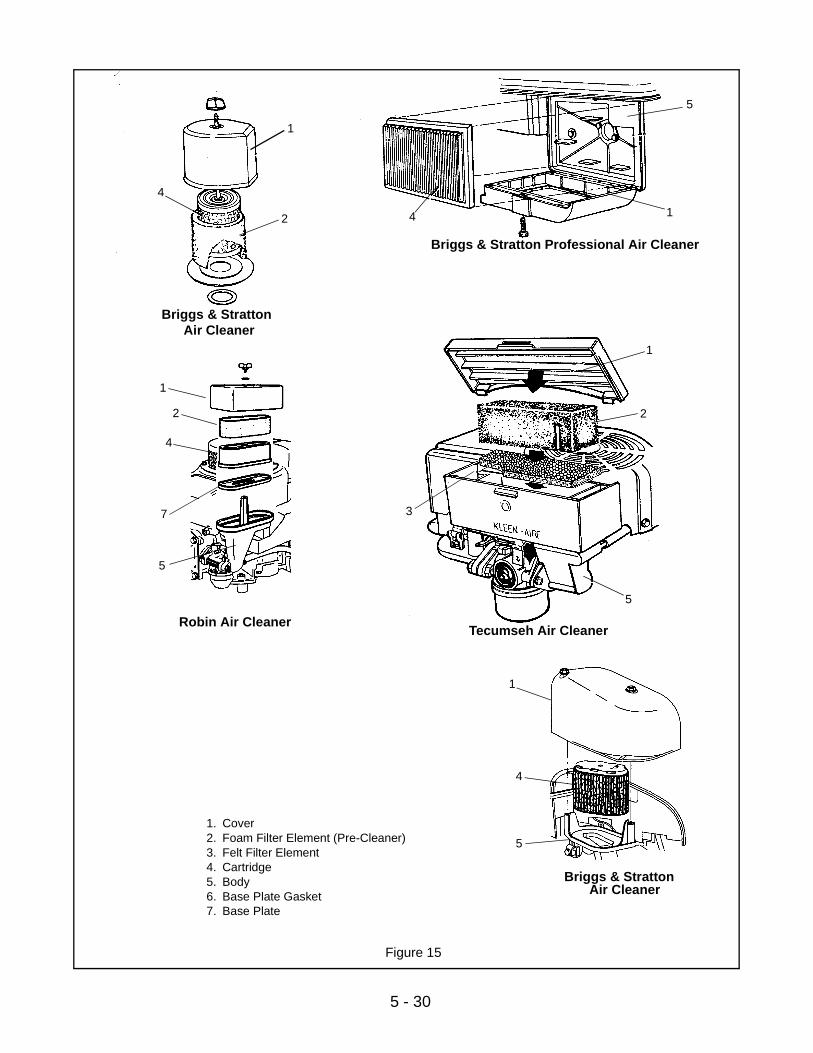
5 - 30
Figure 15
1. Cover2. Foam Filter Element (Pre-Cleaner)3. Felt Filter Element4. Cartridge5. Body6. Base Plate Gasket7. Base Plate
Briggs & StrattonAir Cleaner
Briggs & Stratton Professional Air Cleaner
Tecumseh Air Cleaner1
2
4
5
6
7
2
1
3
5
1
4
5
12
4
Briggs & StrattonAir Cleaner
1
4
5
Robin Air Cleaner
1
2
4
5
7
5 - 31
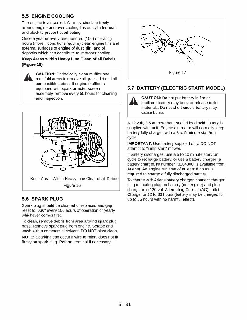
5.5 ENGINE COOLINGThe engine is air cooled. Air must circulate freely around engine and over cooling fins on cylinder head and block to prevent overheating.
Once a year or every one hundred (100) operating hours (more if conditions require) clean engine fins and external surfaces of engine of dust, dirt, and oil deposits which can contribute to improper cooling.
Keep Areas within Heavy Line Clean of all Debris (Figure 16).
5.6 SPARK PLUGSpark plug should be cleaned or replaced and gap reset to .030" every 100 hours of operation or yearly whichever comes first.
To clean, remove debris from area around spark plug base. Remove spark plug from engine. Scrape and wash with a commercial solvent. DO NOT blast clean.
NOTE: Sparking can occur if wire terminal does not fit firmly on spark plug. Reform terminal if necessary.
5.7 BATTERY (ELECTRIC START MODEL)
A 12 volt, 2.5 ampere hour sealed lead acid battery is supplied with unit. Engine alternator will normally keep battery fully charged with a 3 to 5 minute start/run cycle.
IMPORTANT: Use battery supplied only. DO NOT attempt to "jump start" mower.
If battery discharges, use a 5 to 10 minute start/run cycle to recharge battery, or use a battery charger (a battery charger, kit number 71104300, is available from Ariens). An engine run time of at least 8 hours is required to charge a fully discharged battery.
To charge with Ariens battery charger, connect charger plug to mating plug on battery (not engine) and plug charger into 120 volt Alternating Current (AC) outlet. Charge for 12 to 36 hours (battery may be charged for up to 56 hours with no harmful effect).
CAUTION: Periodically clean muffler and manifold areas to remove all grass, dirt and all combustible debris. If engine muffler is equipped with spark arrester screen assembly, remove every 50 hours for cleaning and inspection.
Figure 16
Keep Areas Within Heavy Line Clear of all Debris
CAUTION: Do not put battery in fire or mutilate; battery may burst or release toxic materials. Do not short circuit; battery may cause burns.
Figure 17

6 - 32
6.1 BLADE BRAKE/CLUTCH REMOVALRemove mower blade.
Squeeze brake/clutch bail against handlebar and insert cotter pin into open hole of actuating rod.
Remove 3/8-24x2-1/2" cap screw that retains brake, blade, clutch (BBC) leaf spring and leaf spring from shaft.
Remove BBC flywheel by securing flywheel with BBC wrench (P/N 000239). Remove flywheel and cotter pin securing actuator rod to brake actuator.
Remove three nuts and remove brake actuator from unit.
Inspect parts for wear and or damage, replace as necessary. Assemble in reverse order.
NOTE: When attaching actuator rod to brake actuator, brake actuator is to be rotated all the way up so proper hole is aligned.
On models with key, position key in crankshaft. Slide flywheel onto crankshaft and BBC leaf spring onto flywheel stub shaft.
IMPORTANT: Install 3/8-24x2-1/2" Gr. 5 cap screw and lockwasher to secure. Torque to 30 ft-lbs (40.6 Nm) using BBC wrench to hold leaf spring and flywheel. Secure mower blade with two 3/8-24x1-1/4" Gr. 5 cap screws with lockwashers, torque to 25-30 ft-lbs (33.8-40.6 Nm).
Check idler for free rotation of pulley and movement of pivot.
Replace drive belt in reverse order being sure that belt seats in pulley grooves with idler positioned on back (flat) side of belt.
SECTION 6 - MOWER DECK
Figure 18
1. Drive Belt2. Drive Disk3. Ball Bearing4. Washer5. Spindle
6. Bearing Retainer7. Center Baffle8. Traction Drive Pulley9. Blade Adapter
1
2
3
4
5
6
7
8
9
3
Brake Engaged
Blade Engaged
Figure 19

6 - 33
6.2 DRIVE BELT REPLACEMENT
NOTE: On BBC model blade brake/clutch assembly must be removed to change belt.
Place right rear adjustment lever in first notch and left rear height adjustment lever in third notch. This provides clearance between friction wheel and drive disk.
Remove belt from idler, drive disk and engine pulley. Remove belt through opening under mower pan.
Inspect parts for wear and or damage, replace as necessary.
Assemble in reverse order.
NOTE: Be sure to return wheel height adjustment levers to original position.
6.3 IDLER REMOVALRemove mower blade, hub, and center baffle. Refer to Mower Blade Section of this manual.
Remove idler spring. Loosen hardware securing idler arm to mower pan, and remove cap screw securing idler to idler arm.
Inspect parts for wear and or damage, replace as necessary. Assemble in reverse order.
6.4 WHEELS AND ADJUSTERSRegularly check wheels and adjusters for wear. Replace wheels when they become excessively worn. Adjusters should be cleaned and fasteners checked for tightness.
Check the front wheels for bushing wear. Replace as needed.
CAUTION: Use sturdy gloves or padding to protect hands when working with mower blades.
Figure 20
1. Blade2. Cap Screw, Lock
Washer & Flat Washer3. Leaf Spring
4. Flywheel5. Brake Actuator6. Ramp Assembly
1
2
3
4
5
6
Figure 21
1. Two-Way Lock Nut2. Idler3. Extension Spring4. Center Lock Nut5. Washer
6. Idler Arm7. Flange Bushing8. Tension Spring9. Spacer
Configuration 1
1
2 34
567
1
2
9
7
8
Configuration 2
6 - 34
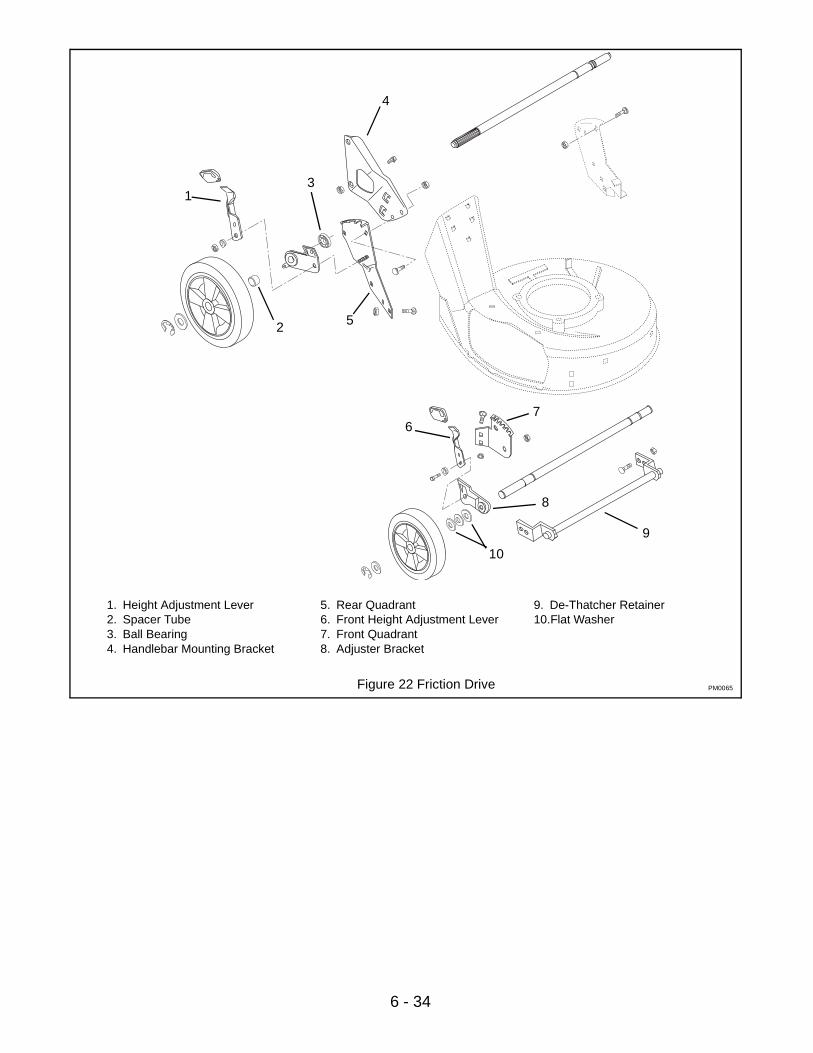
Figure 22 Friction Drive
1. Height Adjustment Lever2. Spacer Tube3. Ball Bearing4. Handlebar Mounting Bracket
5. Rear Quadrant6. Front Height Adjustment Lever7. Front Quadrant8. Adjuster Bracket
9. De-Thatcher Retainer 10.Flat Washer
PM0065
1
2
3
4
5
67
8
9
10
6 - 35
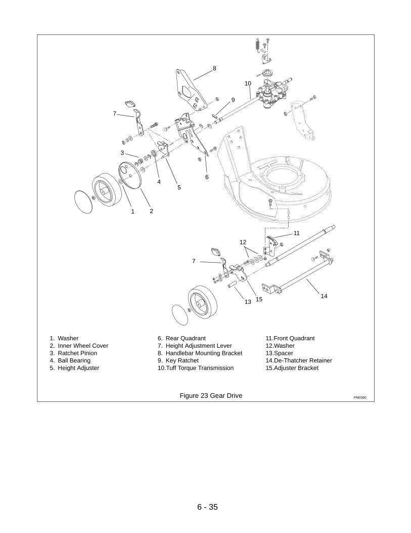
Figure 23 Gear Drive
1. Washer2. Inner Wheel Cover3. Ratchet Pinion4. Ball Bearing5. Height Adjuster
6. Rear Quadrant7. Height Adjustment Lever8. Handlebar Mounting Bracket9. Key Ratchet10.Tuff Torque Transmission
11.Front Quadrant12.Washer13.Spacer14.De-Thatcher Retainer15.Adjuster Bracket
PM0360
1 2
3
45
6
7
8
9
10
11
12
7
141513

6 - 36
Figure 24
1. Kickout Ring2. Sleeve Bushing3. Clevis Pin4. Mount Arm
5. Axle Tab6. Flange Bushing7. Wheel Yoke 8. Lube Fitting
1
23
4
2
5
6
7
8
PM0071

7 - 37
7.1 HANDLEBARS AND BAILSTo remove handlebars:
Remove cable retainers and disconnect cable from bail. Remove push nuts and washers securing bails to handlebars. Remove bails from handlebars.
Remove carriage bolts and washers or knob and washers securing braces to handlebars. Remove braces.
Remove carriage bolt, nut and washer securing handlebar to handlebar bracket. Remove handlebars and inspect parts for wear and or damage. Replace as necessary and assemble in reverse order.
Check all parts for wear and replace as needed.
7.2 SPEED CONTROL BELL CRANKTo adjust models with spring, fully compress compression spring with lock nut and then back lock nut off one turn.
To adjust units without spring:
1. Remove cover and completely compress helical spring lockwashers with locknut, then back off 1/4 turn.
2. If rod is still too loose, tighten nut in small increments until the rod holds.
SECTION 7 - HANDLEBARS & CONTROLS
Figure 25 Friction Wheel Handlebars and Controls
1. Engine Bail2. Handlebar3. Traction Bail4. Cable Anchor5. Cable Anchor Switch
6. Throttle Cable7. Engine Control Cable8. Traction Cable9. Speed Control Brace10.Rivet
11.Speed Control Bracket12.Support Pad13.Speed Control Rod14.Handlebar Adjuster Link
PM0024
1
2
34
5
67
8
9
1011
1213
1414
7 - 38
1
2
3
4
5
6
7
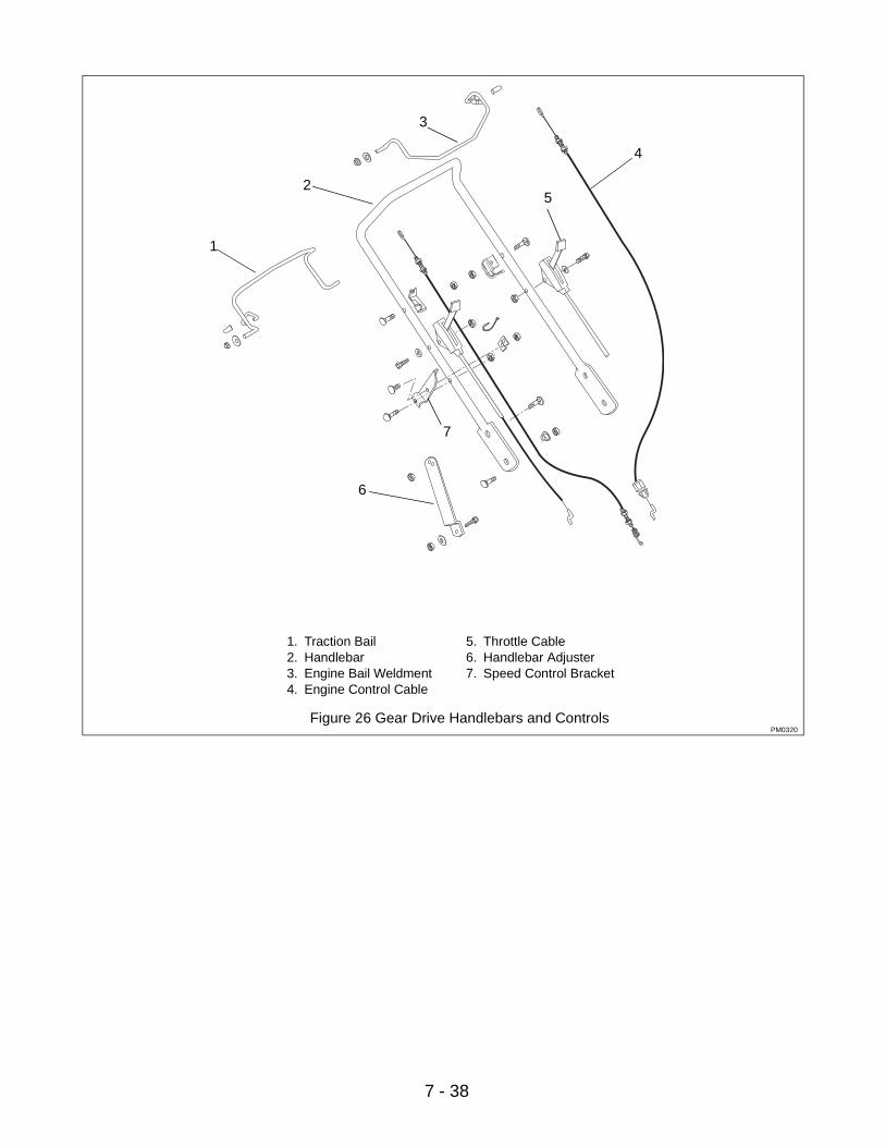
Figure 26 Gear Drive Handlebars and Controls
1. Traction Bail2. Handlebar3. Engine Bail Weldment4. Engine Control Cable
5. Throttle Cable6. Handlebar Adjuster7. Speed Control Bracket
PM0320
8 - 39
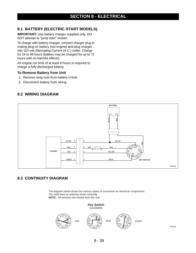
8.1 BATTERY (ELECTRIC START MODELS)IMPORTANT: Use battery charger supplied only. DO NOT attempt to "jump start" mower.
To charge with battery charger, connect charger plug to mating plug on battery (not engine) and plug charger into 110 volt Alternating Current (A.C.) outlet. Charge for 24 to 48 hours (battery may be charged for up to 72 hours with no harmful effects).
An engine run time of at least 8 hours is required to charge a fully discharged battery.
To Remove Battery from Unit1. Remove wing nuts from battery U-bolt.
2. Disconnect battery from wiring.
8.2 WIRING DIAGRAM
8.3 CONTINUITY DIAGRAM
SECTION 8 - ELECTRICAL
S
B
A
M
R
RE
D
BLA
CK
BATTERY
1
2
3
4
A B
KEY SWITCH
RE
DBLACK
REDREDRED
RED YELLOW
WHITE
BLACK
GREEN
ENGINE 1
2
3
4
PM0090
Key Switch(01155800)
OFF
S
B A
MRRUN
S
B A
MRSTART
S
B A
MR
The diagram below shows the various states of connection for electrical components.The solid lines on switches show continuity.NOTE: All switches are viewed from the rear.
PM0100
9 - 40
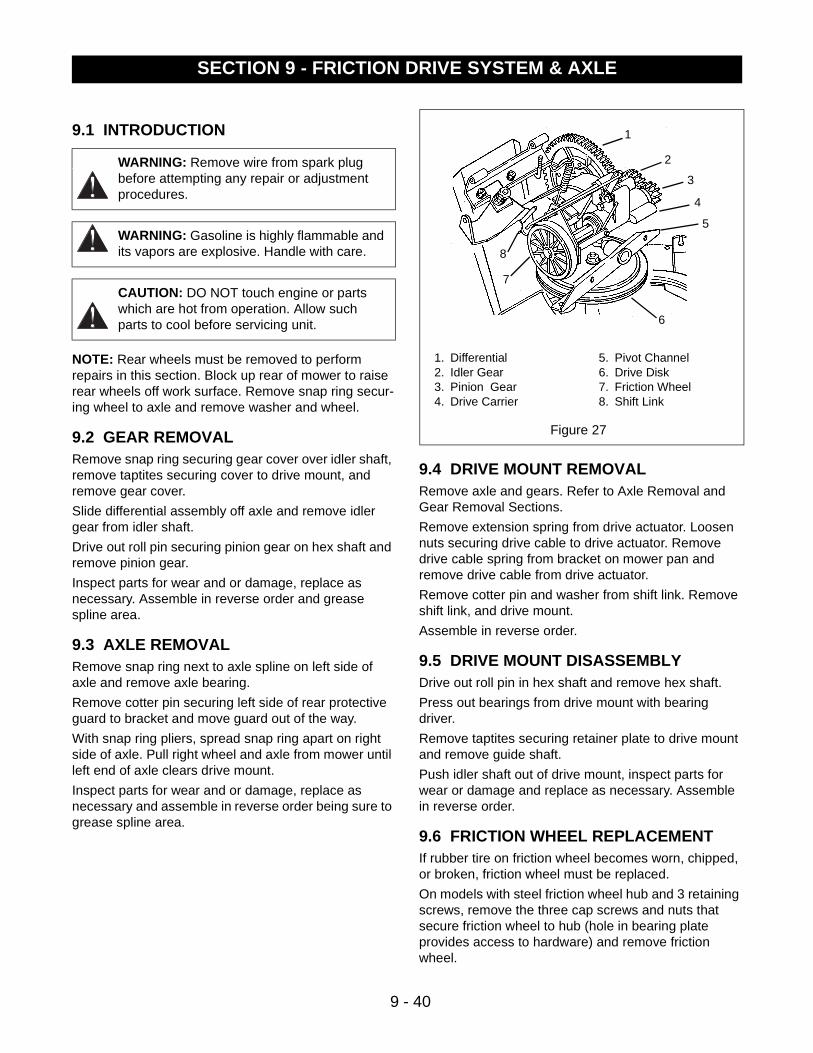
9.1 INTRODUCTION
NOTE: Rear wheels must be removed to perform repairs in this section. Block up rear of mower to raise rear wheels off work surface. Remove snap ring secur-ing wheel to axle and remove washer and wheel.
9.2 GEAR REMOVALRemove snap ring securing gear cover over idler shaft, remove taptites securing cover to drive mount, and remove gear cover.
Slide differential assembly off axle and remove idler gear from idler shaft.
Drive out roll pin securing pinion gear on hex shaft and remove pinion gear.
Inspect parts for wear and or damage, replace as necessary. Assemble in reverse order and grease spline area.
9.3 AXLE REMOVALRemove snap ring next to axle spline on left side of axle and remove axle bearing.
Remove cotter pin securing left side of rear protective guard to bracket and move guard out of the way.
With snap ring pliers, spread snap ring apart on right side of axle. Pull right wheel and axle from mower until left end of axle clears drive mount.
Inspect parts for wear and or damage, replace as necessary and assemble in reverse order being sure to grease spline area.
9.4 DRIVE MOUNT REMOVALRemove axle and gears. Refer to Axle Removal and Gear Removal Sections.
Remove extension spring from drive actuator. Loosen nuts securing drive cable to drive actuator. Remove drive cable spring from bracket on mower pan and remove drive cable from drive actuator.
Remove cotter pin and washer from shift link. Remove shift link, and drive mount.
Assemble in reverse order.
9.5 DRIVE MOUNT DISASSEMBLYDrive out roll pin in hex shaft and remove hex shaft.
Press out bearings from drive mount with bearing driver.
Remove taptites securing retainer plate to drive mount and remove guide shaft.
Push idler shaft out of drive mount, inspect parts for wear or damage and replace as necessary. Assemble in reverse order.
9.6 FRICTION WHEEL REPLACEMENTIf rubber tire on friction wheel becomes worn, chipped, or broken, friction wheel must be replaced.
On models with steel friction wheel hub and 3 retaining screws, remove the three cap screws and nuts that secure friction wheel to hub (hole in bearing plate provides access to hardware) and remove friction wheel.
WARNING: Remove wire from spark plug before attempting any repair or adjustment procedures.
WARNING: Gasoline is highly flammable and its vapors are explosive. Handle with care.
CAUTION: DO NOT touch engine or parts which are hot from operation. Allow such parts to cool before servicing unit.
SECTION 9 - FRICTION DRIVE SYSTEM & AXLE
Figure 27
1. Differential2. Idler Gear3. Pinion Gear4. Drive Carrier
5. Pivot Channel6. Drive Disk7. Friction Wheel8. Shift Link
1
2
3
4
5
6
7
8

9 - 41
Assemble in reverse order. Refer to Section 4.12 to adjust friction wheel drive.
On models with plastic friction wheel hub, remove drive cover nut and remove drive cover. Remove two taptites and snap ring from gear cover and remove gear cover. Remove cotter pin from shift link and move shift link out of way.
Remove three #12-24 x 1/2" taptites from retainer plate. Remove 3/16 x 7/8" roll pin from hex shaft with roll pin driver. Slide hex shaft to left. Slide friction wheel, retainer plate and thrust plate off hex shaft. Remove taptites from thrust plate, separate thrust plate, and remove friction wheel.
Install new friction wheel using reverse procedure.
9.7 DRIVE DISK REMOVALRemove drive belt.
Remove nut, lockwasher and flat washer securing drive disk to mower pan.
Remove four taptites securing bearing retainer to drive disk, remove bearing retainer and spindle.
Press out bearings from drive disk using Ariens Bearing Driver P/N 000026. Replace bearings with Bearing Driver P/N 000046.
Inspect parts for wear or damage and replace as necessary. Assemble in reverse order.
Figure 28
1. Cap Screw2. Friction Wheel
3. Friction Wheel Hub4. Lock Nut
1
2
3
4
Figure 29
1. Taptite2. Thrust Plate
3. Guide Plate4. Friction Wheel
1
2
3
4
Figure 30
1. Nut2. Lock Washer3. Washer4. Drive Disk5. Ball Bearing
6. Washer7. Spindle8. Bearing Retainer9. Taptite10.Carriage Bolt
12
4
5
6
7
9
10
3
8
5
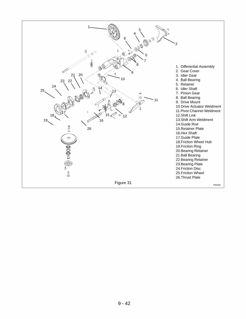
9 - 42
Figure 31
1. Differential Assembly2. Gear Cover3. Idler Gear4. Ball Bearing5. Retainer6. Idler Shaft7. Pinion Gear8. Ball Bearing9. Drive Mount10.Drive Actuator Weldment11.Pivot Channel Weldment12.Shift Link13.Shift Arm Weldment14.Guide Rod15.Retainer Plate16.Hex Shaft17.Guide Plate18.Friction Wheel Hub19.Friction Ring20.Bearing Retainer21.Ball Bearing22.Bearing Retainer23.Bearing Plate24.Friction Disc25.Friction Wheel26.Thrust Plate
1
2
34
5
6
78
9
10
811
12
1314
15
16
1718
19
2021
2223
2524
26
PM0080

10 - 43
10.1 INTRODUCTION
NOTE: Rear wheels must be removed to perform repairs in this section. Block up rear of mower to raise rear wheels off work surface. Remove snap ring secur-ing wheel to axle and remove washer and wheel.
10.2 TRANSMISSION REPLACEMENTThe 3-speed transmission is not repairable. It should be replaced if internal problems develop. To remove the transmission, remove the drive wheels and pinions. Slide the axles out.
1. Remove wheel cover and axle nut to remove wheel and inner cover.
2. Remove drive pinion and axle bearing by removing the two retaining E-clips.
3. Repeat steps 1 and 2 for the other rear wheel.
4. Disconnect the gearshift cable.
5. Unbolt the transmission from the left hand quadrant.
6. Remove drive belt from pulley.
7. Slide the transmission/axle assembly to the right and then down to remove.
8. Install replacement in reverse order. Use pulley and shift linkage from removed unit.
SECTION 10 - GEAR DRIVE SYSTEM & AXLE
WARNING: Remove wire from spark plug before attempting any repair or adjustment procedures.
WARNING: Gasoline is highly flammable and its vapors are explosive. Handle with care.
CAUTION: DO NOT touch engine or parts which are hot from operation. Allow such parts to cool before servicing unit.
1. Transmission-Tuff Torque2. Left Hand Rear Quadrant3. Ball Bearing4. Ratchet Pinion5. Wheel Inner Cover
Figure 32
1
2
34
5

Ariens Company655 West Ryan StreetP.O. Box 157Brillion, WI 54110-0157920-756-2141Fax 920-756-2407www.ariens.com


