Embed Size (px)
Citation preview
1
1. Introduction to Chemical Process & Product
Design
Objectives
After completing this chapter, students should
be able to
appreciate the importance of chemical pro-
cess and plant design
understand the natures of chemical pro-
cess and plant design
know the sequence of process and plant
design
have a basic understanding of the organi-
sation of a chemical engineering project
have a basic knowledge on how to produce
a project documentation

2
know how to specify/identify codes & stan-
dards, design factors, and systems of units
used in the chemical engineering project
understand how to set the design object-
tive(s) and that the design always has a
limitation/constraints

3
1.1 Nature of Chemical Process and Plant Design
Chemical products are essential to modern
society. High living standards depend heavily on
the chemical products
Almost all aspects of our everyday life are
supported by chemical products in one way or
another [1]
Examples of chemical products widely used in
our daily life are illustrated in Figures 1.1-1.6

4
Figure 1.1 Products from poly-ethylene (PE)
(from http://www.ineos.com & http://www.freelin-wade.com)
Figure 1.2 Pharmaceutical products
(from http://www.rc-globalholding.com &
http://www.spotoncoating.com)

5
Figure 1.3 Luxury products from PVC
(from http://www.lyst.com & http://www.ebay.com)
6
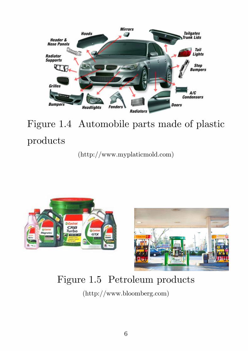
Figure 1.4 Automobile parts made of plastic
products (http://www.myplaticmold.com)
Figure 1.5 Petroleum products
(http://www.bloomberg.com)

7
Figure 1.6 Fragrances
Chemical products can be divided into 3 cate-
gories [1]:
1) Commodity or bulb chemicals:
Produced in large volumes
Purchased on the basis of chemical com-
position, purity, and price
Examples are sulphuric acid, nitrogen,
and oxygen

8
2) Fine chemicals:
Produced in small volumes
Purchased on the basis of chemical com-
position, purity, and price; but with
higher purity and price
Examples include
o chloropropylene oxide (used for the
manufacture of epoxy resins and ion-
exchange resins)
o dimethyl formamide (used as an in-
termediate in the manufacture of
pharmaceutical products)
o n-butyric acid (used in the produc-
tion of beverages, flavourings, and
fragrances)

9
3) Specialty or functional chemicals:
Purchased of their function
High value-added and sold at a very
high margin (or profit)
Short lifetime
Examples are
o Pharmaceutical/healthy products
o flavourings
o perfumes
These chemical products (of any category) are
produced in chemical plants, which were operated
mainly by chemical engineers

10
The creation of plans & specifications and the
analysis of financial feasibility/profitability for
the construction/modification/operation of che-
mical processes/plants to produce chemical pro-
ducts is the activity of chemical engineering de-
sign
Process and plant designs are the focal point
of chemical engineering practice [2]
The development of chemical processes and
plant products is the creative activity [2-3]
The designers of either processes or plants
normally start their designs from specific object-
tives or customers’ needs and arrive at the best
way to achieve such objectives/needs
11
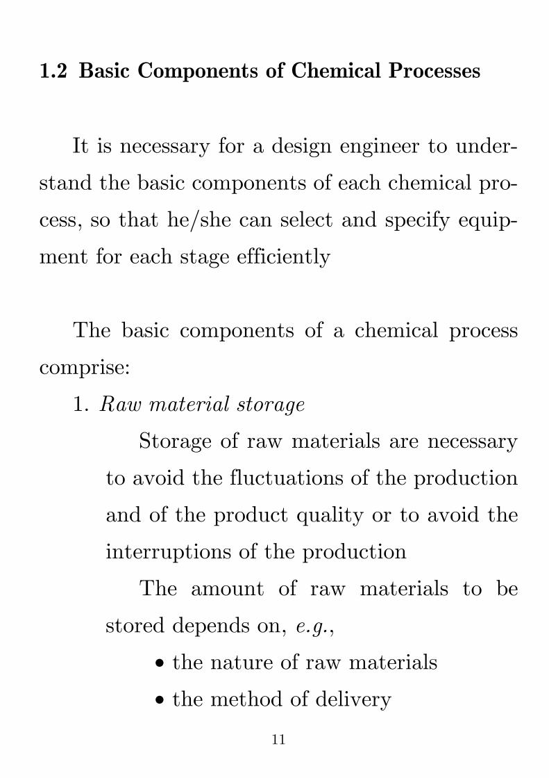
1.2 Basic Components of Chemical Processes
It is necessary for a design engineer to under-
stand the basic components of each chemical pro-
cess, so that he/she can select and specify equip-
ment for each stage efficiently
The basic components of a chemical process
comprise:
1. Raw material storage
Storage of raw materials are necessary
to avoid the fluctuations of the production
and of the product quality or to avoid the
interruptions of the production
The amount of raw materials to be
stored depends on, e.g.,
the nature of raw materials
the method of delivery

12
Storing too high amounts of raw mate-
rials leads to higher capital and operating
costs; on the other hand, if the amount of
raw materials stored is not sufficient, it can
result in the interruption of the process
2. Feed preparation
This stage is required to prepare the
raw materials to be, e.g.,
at the appropriate purity
in the right form/size
free of contaminants that can be
poison to the catalysts
3. Reaction
This stage is the most important
stage (or the heart) of a chemical process.
The design engineer must design the
reactor such that the desired product(s)
is(are) produced at the desired amount

13
4. Separation
In this stage, the desired product(s) are
separated from the by-product(s) and the
un-reacted reactant(s)
At times, the un-reacted reactant(s)
is(are) recycled to the reaction or the feed
preparation stage
5. Purification
In this stage, the main product(s)
is(are) purified using various kinds of tech-
niques, in order to meet the standard(s) or
market/customer need(s)
6. Product storage and sales
The amount of product(s) to be stocked
before sales depends on the nature of the
product(s) and/or the market/customer
demand(s)

14
In addition to the basic components of chemi-
cal processes, auxiliary processes producing and
supplying such services or utilities as
process water
cooling water
air/process gas (e.g., nitrogen, oxygen)
steam
are also needed for each component of a chemical
process
The design engineer must not overlook these
services/utilities

15
1.3 Choice of Continuous vs Batch Production
As students have already learned from the
course of Material & Energy Balances,
Continuous processes are designed to oper-
ate 24 hours a day, 7 days a week, through-out a long period of time (e.g., a year)
The operating rate (commonly called
the attainment percentage) of the conti-
nuous process can be determined by the
following equation:
Number of hours
actually operated% Attainment 100
8,760
é ùê úê úê úë û= ´
(1.1)
Generally, % attainment of continuous
processes ranges from 90-95% on annual
basis

16
Batch processes are designed to run inter-
mittently (for a certain period of time; e.g.,
10 hours, depending on the nature of the
chemical process)
It should be noted that the combination of
continuous and batch operations is common for
chemical processes; for example, a batch reactor
is employed to produce the mixture of ethanol +
water at a low concentration of ethanol through
fermentation, and this mixture of ethanol + water
is used as a feed to a continuous distillation
column to produce ethanol with a higher purity
Continuous processes are usually more econo-
mical than batch processes, especially for large-
scale production, as their capital/fixed costs are
much lower (for a high-volume production)

17
However, batch processes are more flexible, as
they allow the production of multiple products
with different grades/purities in the same equip-
ment; additionally, they are easier to clean and
maintain sterile operation
Accordingly,
the continuous processes are the best
choice for producing commodity or bulb
chemical products
the batch processes are highly recommended
for specialty or functional chemical products
Fine chemical products can be produced by
either continuous or batch processes, depending
on the quantity produced.

18
1.4 Organisation of a Chemical Engineering
Project
The structure of a chemical engineering pro-
ject can be listed sequentially as follows
1. Project specification (setting the design ob-
jectives or determining customers’ needs)
In this stage, the designer should obtain
as clear and unambiguous requirements as
possible
The needs can be categorised into
Must-have: cannot be compromised
during the design
Should-have: can be relaxed during
the design

19
Additionally, in this stage, the design
basis is set; the design basis is a more pre-
cise statement of the design problem, e.g.,
production rate and purity specifications,
along with constraints that will affect the
design, such as
the international, national, local, or
company’s standards/codes
the details of raw materials avail-
able
information regarding the possible
plant location(s), e.g., climate data,
seismic condition, infra-structure
availability
information concerning the condi-
tions, availability, and price of utili-
ties (e.g., electricity, water supply,
fuels)

20
It is necessary to have a clearly defined
design basis before detailed design can be
started
2. Determination of possible designs/choices
In this stage, possible solutions to the
design problem are to be analysed, evalu-
ated, and selected
For example, the possible ways of in-
creasing the plant capacity for producing a
higher amount of polymer according to an
increase of the market need are [1]
Choice 1: 10% increase, with a mo-
dest capital cost
Choice 2: 20% increase, with a sig-
nificant capital cost
Choice 3: 30% increase, with an ex-
tremely huge capital cost
Choice 4: Build a new plant

21
When the choice is selected, the next
steps (i.e. the economic evaluation and the
detailed design & equipment selection) will
be proceeded according to the selected
choice
Generally, chemical engineering pro-
jects can be categorised into 3 types:
1) Modifications to the existing plant,
to, e.g., increase the purity of the
product, or to lower the emissions
of pollutants
2) Expansion of the existing plant, to
meet the growing demand
3) Development of the new process/
plant

22
The next step is to examine the fitness of
the designs/choices, which includes the se-
lection of the process and the sketch of flow
diagrams
In this stage, the designer must evalu-
ate each design/choice to see how well it
fit the purpose (objective/need)
Process simulation software package
(e.g., Aspen Plus® or Aspen HYSYS® or
Pro/II®) are to be employed to test the
choices
3. Performing material & energy balances
4. Preliminarily selecting & designing process
equipment
In this stage, the detailed specifications
of equipment in the chosen process, e.g.,
vessels, heat exchangers, pumps, reactors,

23
and distillation columns, are specified (by
chemical & mechanical engineers)
Control systems are also examined and
selected (by chemical & electrical engineers)
Additionally, plant site preparation for
further construction is to be made (by civil
engineers)
At times, these tasks are carried out by
an Engineering, Procurement, and Con-
struction (EPC) company (or a contractor).
5. Formulating the process flow diagram
(PFD); an example of PFD is depicted in
Figure 1.7

24
Figure 1.7 An example of a process flow diagram
(PFD) (from http://chemengineering.wikispaces.com)
6. Preliminarily estimating process/plant costs
and acquiring the source of funds
After selected design(s)/choice(s) can
be chosen from Stage 2 & 4, economic per-
spective of each design/choice will be ana-
lysed

25
In addition to economic analysis, effects
on human’s health/hazards and the envi-
ronment will (must) also be determined
7. Piping & instrumentation design [an exam-
ple of piping & instrumentation diagram
(P & ID) is as shown in Figure 1.8] and
detailed process design, which includes
selecting/designing chemical engineering
equipment
selecting/specifying instrument & con-
trol systems
selecting/specifying pumps & compres-
sors
a reactor design
a heat exchanger design
selecting/specifying/designing separa-
tion equipment

26
Figure 1.8 An example of piping & instrumenta-
tion diagram (P & ID) (from http://www.creativeengineers.com)
a piping design
designing/specifying utilities & other
services
selecting/specifying electrical motors,
switch gear, and sub-stations

27
8. Structural & plant layout design, which
comprise
a structural design
a plant layout design
designs of general civil works, foun-
dations, drainage systems, and roads
designs of offices, laboratories, and con-
trol rooms
9. Project cost estimation & fund authorisa-
tion
10. Procurement/purchasing
11. Construction
12. Start-up (or commission)
In this stage, even though the plant is
fully operational, it is not for commerciali-
sation yet; the purpose of this stage is to
examine whether or not the plant is ready

28
During this start-up period, the design
engineer must be ready to be called to
resolve the start-up and operating problem
13. Operation
Up to this point, the plant is ready for
commercial operation
14. Sales (including Marketing)
1.5 Project Documentation
Since the chemical engineering project is very
complicated and requires the co-operation of
several groups, it is necessary to have an effective
and well-organised documentation, which include
Correspondence within the design group
and with, e.g.,
o government departments
o the client
o vendors
29
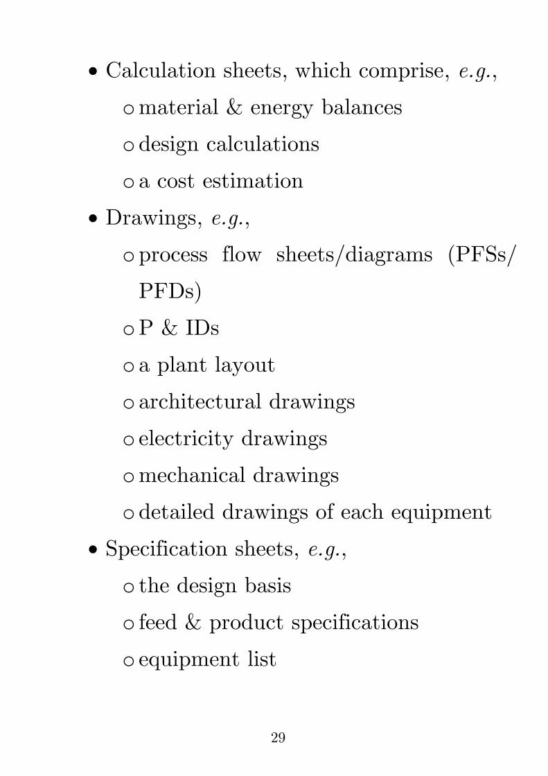
Calculation sheets, which comprise, e.g.,
o material & energy balances
o design calculations
o a cost estimation
Drawings, e.g.,
o process flow sheets/diagrams (PFSs/
PFDs)
o P & IDs
o a plant layout
o architectural drawings
o electricity drawings
o mechanical drawings
o detailed drawings of each equipment
Specification sheets, e.g.,
o the design basis
o feed & product specifications
o equipment list

30
o detailed specifications of each equip-
ment
Information on health, safety, and the en-
vironment, e.g.,
o material safety data sheets (MSDSs);
an example of MSDS is as illustrated in
Figure 1.9
o HAZOP or HAZAN documentation (will
be discussed in detail later)
o documents concerning emission assess-
ments
Purchase orders, e.g.,
o quotations
o invoices

31
Figure 1.9 An example of a material safety data
sheet (MSDS) (from http://www.zeofill.com)
32
Process manuals: describing the process
and the basis of the design, which provide
a complete technical description of the pro-
cess; generally, process manuals are ac-
companied by PFDs/PFSs and P & IDs
Operating manuals: the detailed, step by
step, instructions for the operation of the
whole process and of each equipment
1.6 Codes and Standards
Nowadays, the standardisation is needed;
thus, all the design of chemical processes must
follow codes and standards strictly
There are several codes and standards to be
complied with, e.g.,

33
International Organisation for Standardi-
sation (ISO): http://www.iso.org/
British Standards (BS):
http://www.bsigroup.com/en-GB/
German Institute for Standardisation or
Deutsches Institut für Normung (DIN):
http://www.din.de/
American National Standards Institute
(ANSI): http://www.ansi.org/
American Society for Testing and Mate-
rials (ASTM): http://www.astm.org/
Japanese Industrial Standards (JIS):
http://www.jisc.go.jp/eng/
Thai Industrial Standards (TIS: มอก):
http://www.tisi.go.th/eng/

34
1.7 Design Factors
Since errors and uncertainties arising from the
data and approximation are unavoidable, it is
common for the designer to include some degrees
of over-design, commonly known as design fac-
tor or safety factor [1-2]
Concerning the design/safety factor, the de-
signer should keep in mind that
if design/safety factor is too low, the pro-
cess might not work or it may run at a high
risk
on the contrary, if the design/safety factor
is too high, it would cause the process to
be unnecessarily expensive or less efficient

35
Thus, a balance must be made between these
two extremes [1]
1.8 Systems of Units
Even though modern engineering design is
based on SI units, traditional scientific (i.e. metric
system) and engineering [i.e. American Engi-
neering (AE) system] are still widely employed
Additionally, some useful data are also avail-
able in metric and AE systems
Accordingly, design engineers must be familiar
with other unit systems (as mentioned above), in
addition to SI units, and must be able to make a
conversion between the unit systems fluently

36
The following are the examples of the units
commonly used in chemical process design:
Temperature is presented in oC or oF, ra-
ther than K or R
Pressure is commonly given in bar, rather
than Pa (N/m2) or atm
Volume or volumetric flow rate is provided
in L or L/time, rather than m3 or m3/time,
which gives too small values
kg or tonnes (103 kg) used normally em-
ployed to describe plant capacities; g gives
too high values and Gg (gigagramme – i.e.
109 g) is rarely used
In the USA, M is used for 103, and MM is
used for 106, which can be confusing to
those familiar with SI or metric units
(where k and M are used for 103 and 106,
respectvely)

37
It is highly recommended that design engi-
neers clearly specify the unit systems used in the
project before the start of the design process
1.9 Design Objectives and Constraints
In the design process, it must have the design
objective(s) for the whole process or for each sub-
process
The design objective is to either minimise or
maximise a specific quantity
For example, to
maximise a profit
minimise a cost or emissions

38
However, the design objective(s) always has
(have) a limitation (limitations), which is generally
called constraints
Examples of constraints are as follows
Product purity ≥ 99.99 wt%
Production rate ≤ 500,000 tonnes/year
NOx emissions ≤ 200 ppm
In order to satisfy the design objective(s), a
design engineer must be able to translate the
design objective(s) and constraint(s) into equa-
tion, in order to be able to solve for the suitable
values of variables related to the design ob-
jective(s) and constraint(s) that lead to the
satisfaction of the design objective(s), which is
commonly called optimisation

39
An example of an optimisation problem is as
illustrated below:
Maximise: 2
1 23 5z x x= +
(this is an objective)
Constraints: 1 2
10x x+ =
1
4x ³
The obtained values of 1
x and 2
x must satisfy
all objectives and constraints

40
References
[1] R. Smith, Chemical Process: Design and Integration,
Wiley, 2005.
[2] R. Sinnot and G. Towler, Chemical Engineering
Design: Principles, Practice, and Economics of Plant
Design, 2nd ed., Elsevier, 2013.
[3] R. Turton, R.C. Bailie, W.B. Whiting, J.A. Shaeiwitz,
and D. Bhattacharyya, Analysis, Synthesis, and Design
of Chemical Processes, 4th ed., Pearson, 2013.