Embed Size (px)
Citation preview

MAE 656 - Advanced Computer Aided Design
01. Introduction – Doc 03
Numerical Simulation of Truss Elements

Introduction
The main aim of this lesson is to present the basic of a numerical calculation: If we can transform a calculation in a repetitive procedure we can send it to a computer and it will do it for us. A computer cannot think but can perform calculations substantially faster than us.
MAE 656 – cba Dr. Xavier Martinez, 2012 01. Intro – Doc 03
If we tell the computer how to calculate this:
It can afterwards calculate this:
Or this:
Introduction
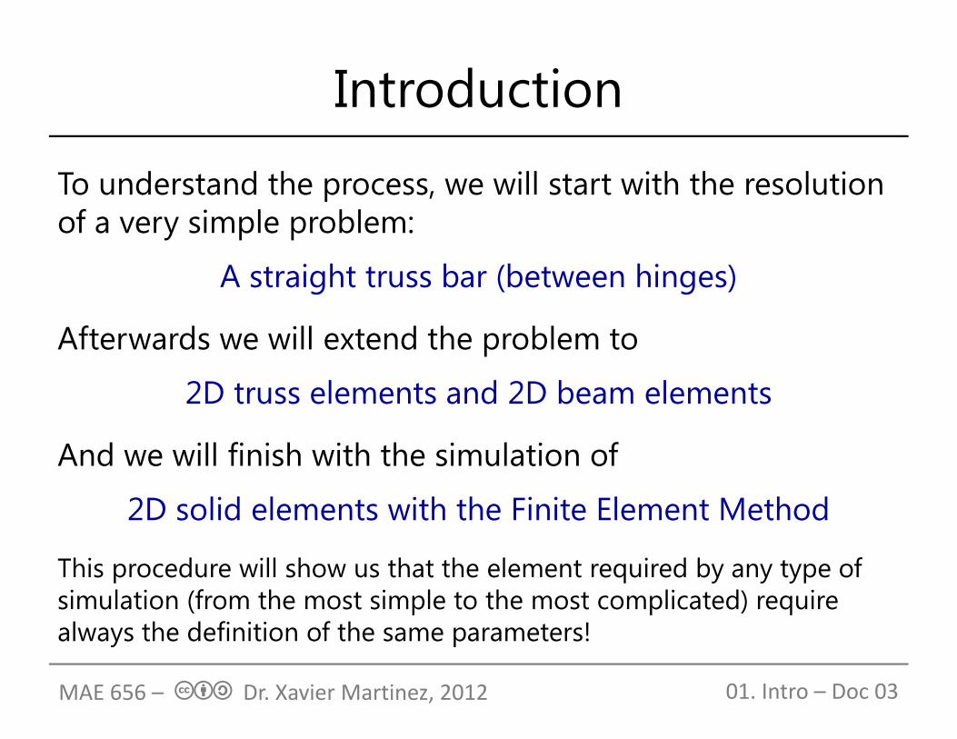
To understand the process, we will start with the resolution of a very simple problem:
A straight truss bar (between hinges)
Afterwards we will extend the problem to
2D truss elements and 2D beam elements
And we will finish with the simulation of
2D solid elements with the Finite Element Method
This procedure will show us that the element required by any type of simulation (from the most simple to the most complicated) require always the definition of the same parameters!
01. Intro – Doc 03MAE 656 – cba Dr. Xavier Martinez, 2012

Single bar between hinges
∙ ∙
∙∙
∙
0;
if the bar is in equilibrium:
→
01. Intro – Doc 03MAE 656 – cba Dr. Xavier Martinez, 2012

Single bar between hinges
The forces of each node can be computed as:
Which can be written as a matrix:
∙∙
∙∙
∙∙ 1 1
1 1 ∙
∙ ∙
∙ ∙ ∙
Thus, it is possible to obtain the forces on each node of a truss from the displacement of its nodes:
01. Intro – Doc 03
element stiffness matrix
MAE 656 – cba Dr. Xavier Martinez, 2012

Three bars between hingesLet’s see how the previous formulation can be used to solve:
For each bar we can write:
∙∙ 1 1
1 1 ∙
∙∙ 1 1
1 1 ∙
∙∙ 1 1
1 1 ∙
01. Intro – Doc 03MAE 656 – cba Dr. Xavier Martinez, 2012

Three bars between hinges
Previous three equations are valid for any case. However, for our particular structure:
;
;
;
;
;
;
and
01. Intro – Doc 03MAE 656 – cba Dr. Xavier Martinez, 2012

Three bars between hinges
Therefore: ∙ 1 11 1 ∙
∙ 1 11 1 ∙
∙ 1 11 1 ∙
∙with,
We’ve been able to relate all forces and displacements of the structure using the stiffness of all bars composing it!
01. Intro – Doc 03MAE 656 – cba Dr. Xavier Martinez, 2012

Three bars between hinges
we can write now the global system of equations:
∙ 1 11 1 ∙ ∙ 1 1
1 1 ∙
∙ 1 11 1 ∙
having:
01. Intro – Doc 03
structure stiffness matrix
MAE 656 – cba Dr. Xavier Martinez, 2012

Three bars between hinges
we can write now the global system of equations:
∙ 1 11 1 ∙ ∙ 1 1
1 1 ∙
having:
01. Intro – Doc 03
structure stiffness matrix
∙ 1 11 1 ∙
MAE 656 – cba Dr. Xavier Martinez, 2012

Three bars between hinges
we can write now the global system of equations:
∙ 1 11 1 ∙ ∙ 1 1
1 1 ∙
having:
01. Intro – Doc 03
structure stiffness matrix
∙ 1 11 1 ∙
MAE 656 – cba Dr. Xavier Martinez, 2012
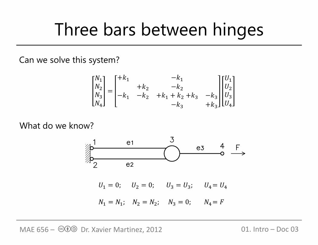
Three bars between hingesCan we solve this system?
What do we know?
0; 0; ;
; ; 0;
01. Intro – Doc 03MAE 656 – cba Dr. Xavier Martinez, 2012

Three bars between hinges
0
00
therefore,
and the resulting system that has to be solved is:
0
Once knowing the values of U3 and U4, we can use the complete system to calculate reactions N1 and N2
01. Intro – Doc 03MAE 656 – cba Dr. Xavier Martinez, 2012

Can we systematize it?Bar connectivities:
01. Intro – Doc 03MAE 656 – cba Dr. Xavier Martinez, 2012

Can we systematize it?Bar connectivities:
01. Intro – Doc 03MAE 656 – cba Dr. Xavier Martinez, 2012

Can we systematize it?Bar connectivities:
The stiffness matrix is defined adding the stiffness of each bar element at the position of the nodes that define the bar.
01. Intro – Doc 03MAE 656 – cba Dr. Xavier Martinez, 2012

Can we systematize it?
⋮
⋮
⋮ ⋮⋯ ⋯
⋮ ⋮⋯ ⋯
⋮
⋮
In general:
The stiffness matrix of the structure is defined by the mechanical characteristics of the bar ke (E, A, L) and the connectivities of the different bar elements.
Column j
Column i
Row i
Row j
01. Intro – Doc 03MAE 656 – cba Dr. Xavier Martinez, 2012

Can we systematize it?Boundary Conditions:
01. Intro – Doc 03
Nodes with known forces (=F)
Nodes with known forces (=0)
Nodes with unknown forces butknown displacements
To solve the problem we will remove from the system all rows and columns of the nodes. The resulting system of equations is perfectly defined and can be solved to obtain the displacements of all the structure.
MAE 656 – cba Dr. Xavier Martinez, 2012
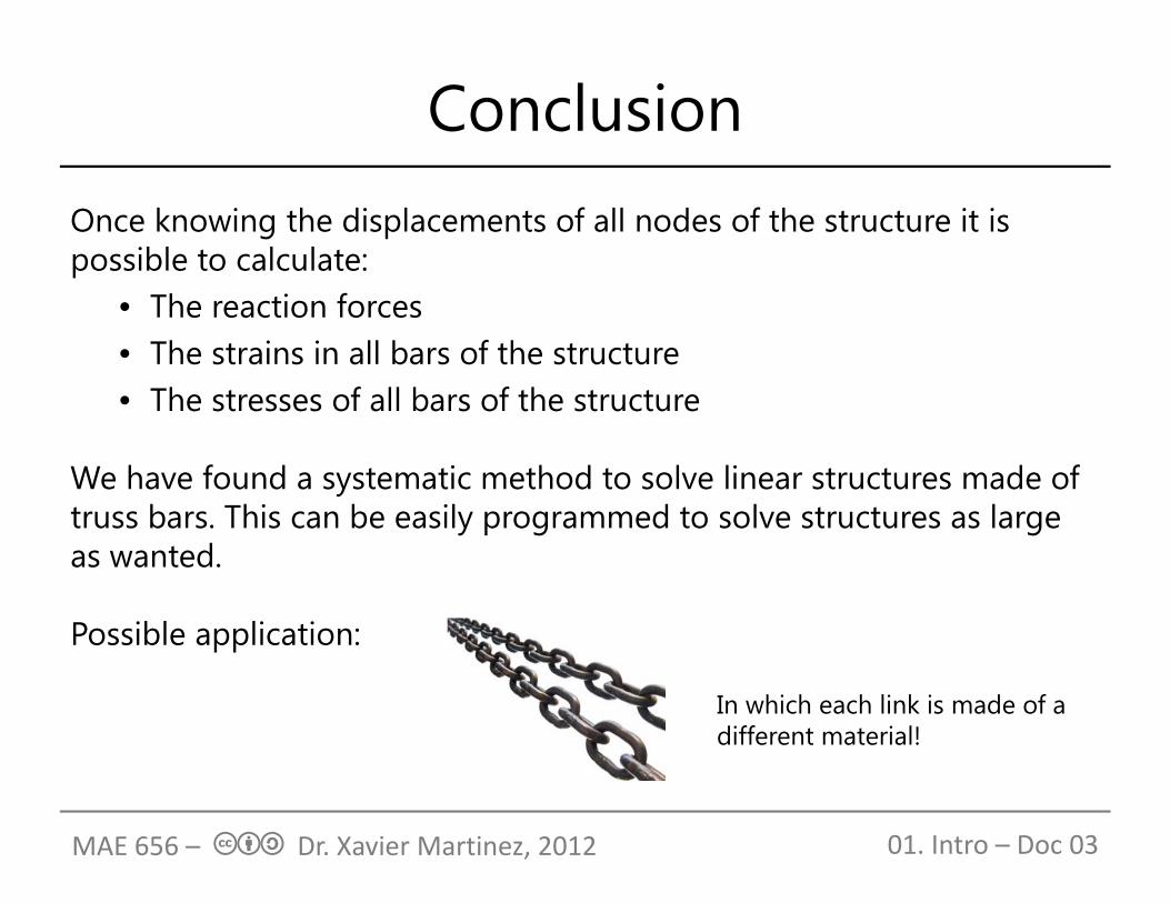
ConclusionOnce knowing the displacements of all nodes of the structure it is possible to calculate:
• The reaction forces• The strains in all bars of the structure• The stresses of all bars of the structure
We have found a systematic method to solve linear structures made of truss bars. This can be easily programmed to solve structures as large as wanted.
Possible application:
01. Intro – Doc 03
In which each link is made of a different material!
MAE 656 – cba Dr. Xavier Martinez, 2012

2D Truss StructuresIf the structure is 2D, the bar element can be defined with any possible angle respect the horizontal. In a general case:
01. Intro – Doc 03
∙ cos ∙ sin
∙ cos ; ∙ sin
where:
MAE 656 – cba Dr. Xavier Martinez, 2012

2D Truss StructuresDefining L, the rotation matrix, as:
It is possible to rewrite the relations between the un-rotated and the rotated beam as:
In the un-rotated configuration:
01. Intro – Doc 03
cos sin
cossin ∙ ∙
cos sin ∙ ∙
∙ 1 11 1 ∙
MAE 656 – cba Dr. Xavier Martinez, 2012
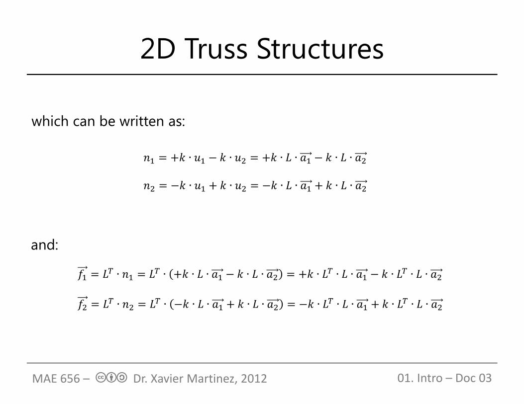
2D Truss Structures
which can be written as:
01. Intro – Doc 03
∙ ∙ ∙ ∙ ∙ ∙ ∙ ∙ ∙ ∙ ∙ ∙
∙ ∙ ∙ ∙ ∙ ∙ ∙ ∙ ∙ ∙ ∙ ∙
∙ ∙ ∙ ∙ ∙ ∙
∙ ∙ ∙ ∙ ∙ ∙
and:
MAE 656 – cba Dr. Xavier Martinez, 2012

2D Truss Structures
01. Intro – Doc 03
∙ ∙ ; ∙ ∙
∙ ∙ ; ∙ ∙
where:
Now it is possible to relate the force and displacement vectors as:
∙ ∙
being: ∙ cos
sin ∙ cos sin cos cos ∙ sincos ∙ sin sin
MAE 656 – cba Dr. Xavier Martinez, 2012

2D Truss StructuresFor a general case:
⋮
⋮
⋮ ⋮⋯ ⋯
⋮ ⋮⋯ ⋯
⋮
⋮
Column j
Column i
Row i
Row j
01. Intro – Doc 03
with: 1 ∙
∙∙ cos cos ∙ sincos ∙ sin sin Note: Positive angle
counterclockwise
MAE 656 – cba Dr. Xavier Martinez, 2012

Implementation (1/2)1. Define the stiffness matrix:
Size = (2 x # nodes) x (2 x # nodes)
2. For each bar of the structure: a. Get/read the bar properties (E, A, L, )b. Compute its stiffness matrix kij
c. Add the bar to the structure stiffness matrix in the position i, j defined by the bar nodes (i, j)
3. Define the forces and displacement vectors. Size = (2 x # nodes) x 1
4. Fill the force vector with the forces applied to the structure. The rest of the nodes will have force zero or unknown.
01. Intro – Doc 03MAE 656 – cba Dr. Xavier Martinez, 2012

Implementation (2/2)5. Remove the rows and columns of the linear system corresponding
to those nodes with the displacement equal to zero (x or y)
6. Solve the linear system of equations
01. Intro – Doc 03MAE 656 – cba Dr. Xavier Martinez, 2012
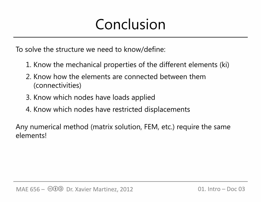
ConclusionTo solve the structure we need to know/define:
1. Know the mechanical properties of the different elements (ki)
2. Know how the elements are connected between them (connectivities)
3. Know which nodes have loads applied
4. Know which nodes have restricted displacements
Any numerical method (matrix solution, FEM, etc.) require the same elements!
01. Intro – Doc 03MAE 656 – cba Dr. Xavier Martinez, 2012