Embed Size (px)
Citation preview
FMGM 2015 – PM Dight (ed.) © 2015 Australian Centre for Geomechanics, Perth, ISBN 978-0-9924810-2-5
FMGM 2015, Sydney, Australia 93
Precision survey monitoring with a reflectorless total station
CJ Hope Monir Precision Monitoring, Canada
SW Dawe Monir Precision Monitoring, Canada
Abstract This paper provides a summary of the state of practice of reflectorless precision survey monitoring using a manual total station to track and record movements. Topics covered include instrument selection, achievable accuracy under varying and challenging conditions, sources of error, reflectorless controls and establishing accurate baseline readings. The authors provide their opinion, with respect to when this technology is a valuable alternative to standard surveying and when it is not applicable. Abbreviated case studies from projects located in downtown Toronto, Ontario, Canada, are used to provide examples of practical and technical aspects of reflectorless precision survey monitoring. The abbreviated case studies include monitoring of high voltage transmission towers in an electrical substation with a deep excavation nearby, background measurements on the Head‐House at Union Station (a historic structure) over four seasons, and taking measurements of adjacent buildings when access is difficult for target installation. A comparison of precise measurements versus reflectorless measurements used for precision survey monitoring is also included. The authors feel this paper will be a useful reference for determining when to use reflectorless monitoring instead of more standard manual monitoring.
1 Introduction Surveyors involved in the monitoring field have most likely learned the problems of installing and monitoring targets on structures and shoring during their career. Sometimes, however, it is not possible to install targets where the shoring or structure needs to be measured. Whether due to inaccessible areas, areas deemed too dangerous to enter or unreceptive neighbours who will not allow the installation of targets, it is still possible to take readings and collect data under the right conditions. Due to the many variables that encroach on the physical world, surveyors must be extremely cautious with the management of errors and must have an understanding of which variables can affect readings. In field applications, reflectorless precision surveying monitoring is used to protect lives, provide cost savings, verify design assumptions and reduce risks when traditional targets cannot be used. In theory, these are simple and easy benefits to realise. In practice, these benefits may be difficult to measure and record due to site conditions, access problems, stakeholder unfamiliarity, and budgetary constraints.
2 A short history of distance measurement It was not until mankind left his nomadic lifestyle and began to settle down that we see the importance of distance measurement. As societies grew and became more complex, so did the need for better accuracies in distance measurement. Today there are a number of technologies that are used to measure distances to very high accuracies in a variety of different applications.
Historically, distances were measured using a variety of means. Some of the earliest techniques included using body parts such as the length of a person’s arm. As societies advanced, we saw the introduction of more consistent means of measuring distance, from the original platinum one metre rule, created by the French during the French revolution, to using chains which were constructed of standardised links of a known length. Eventually, survey tape replaced chains which were constructed of steel and invar. In the 1880s, a Scottish firm by the name of Barr and Stroud developed an optical range finder which was used to measure distance. Tacheometry (Greek for fast measurement) is the science of measuring distances by measuring the angle between two ends of an object with a known size, and was sometimes used prior to

Precision survey monitoring with a reflectorless total station CJ Hope and SW Dawe
94 FMGM 2015, Sydney, Australia
the invention of electronic distance measurement (EDM) where rough ground made chain measurement impractical.
Some of the more recent advances in distance measurement technologies occurred in the 20th Century with the introduction of radar in the 1940s and then in the 1960s, with advances in laser technology, we saw the emergence of EDM technologies.
Until recently, the only means of measuring an electronic distance was combining EDM technology with a retro prism. In the past 20 years, one of the most significant advancements in EDM technologies has been the introduction of Reflectorless EDM. Today, Reflectorless EDM technology has become a standard surveying technique used in various applications where it is either not practical to place a retro prism because of access or because it is unsafe to place retro prisms.
Today a number of companies are manufacturing Reflectorless EDM technologies for use in various industries which include some of the following — construction, engineering and surveying. They come with various types of ranges, accuracies, and features. Some of the major companies offering this technology include Leica Geosystems, Trimble, and Topcon.
3 Recommended practises
3.1 Instrument selection
While there are many reflectorless total stations on the market, many are not sufficiently precise for most precision monitoring applications. A precision reflectorless instrument is generally one with published specifications of 2 mm + 2 ppm or less in the EDM and one second or less in the angular measurement. The instrument used in the writing of this paper was a Leica TS30. Ideally, instruments manufactured for precision monitoring will offer the best accuracy for the measurements, as they are purpose built for the job and come with on‐board compensators and specialised reflectorless measurement technology.
3.2 Accuracy and precision
In theory, any reflectorless total station can be used to attempt a reflectorless monitoring project. However, due to the nature of the work, the practice is much more difficult than would be expected.
One of the best ways to guarantee precise results is to use the same geometry, instrument and operator for all of the readings. While this is not always possible in reality, using the same geometry as much as possible is one of the most important steps to follow. While reflectorless total stations can measure to inaccessible locations, it can be hard to know what happens to the laser as it travels to and from the monitoring point or even if it is hitting the right point. Measuring to the wrong type of surface, not understanding the properties of the laser and how it is affected by atmospheric conditions and the impact of those conditions on the measurements all have varying effects. These are some of the questions that we feel need to be answered and it is also important to understand what the instrument is capable of and under what conditions it operates at its best.
High humidity, fog, precipitation of any kind, bad lighting, vibration, dust, smoke and strong winds will all impact the accuracy of the measurements.
3.3 Controls and baseline readings
Figure 1 illustrates a typical control network. Controls can be precision targets, reflectorless points or a combination of the two.
Reflectorless controls have to be located and lines of sight have to be planned very carefully before any readings are taken. Any reflectorless control point needs to be on a smooth surface, not more than eighty metres away with a clear line of sight.

Case studies
FMGM 2015, Sydney, Australia 95
Figure 1 Site plan showing control point locations (Hope 2007)
To gain the most reliable repeatability, it is vitally important to pick points that are readily identifiable through the telescope with as small a chance of ambiguity as possible. Some examples of these are paint marks already on structures and buildings, flat bolts, ink marks, nail heads, imperfections in colour or marks on bricks and masonry. Keep in mind that the points may have to be read during rainy periods so they should also be visible when wet.
Ten to twelve control points on as many axes as possible is an ideal configuration for a control network with two axes as the minimum; just make sure that the structures that have controls on are not going to move too much while you are monitoring.
Be careful of indentations in surfaces; they look good and are easy to find again but due to their depth, it is very difficult to repeat the original measurement unless you can use the same reading location that was used for the original measurements (the same geometry).

Precision survey monitoring with a reflectorless total station CJ Hope and SW Dawe
96 FMGM 2015, Sydney, Australia
3.4 Using both faces of the instrument
Using the instrument in both faces will control any calibration errors in the instrument and is needed for the accuracy it provides for reflectorless readings. By taking readings on both faces of the instrument multiple times, the repeatability of the initial measurements to the controls and the monitoring points can be kept within a tolerable range as long as the correct procedures are followed. If large differences are noted between readings on either face of the instrument then a change in geometry to a more perpendicular location is recommended.
3.5 Perpendicular problems
The plan below illustrates the angular ranges for precise and reflector less readings. This also applies to readings on the vertical plane.
Figure 2 Diagram Showing Angular Range for reflectorless readings (Monir Precision Monitoring, May 2015)
By keeping measurement angles within an 80 degree range as much as possible, the laser will return an accurate and precise location of the point. A way to think of this is to stay as perpendicular to as many monitoring points as is possible. Any monitoring or control point should be within 40 degrees of the perpendicular for the most consistent and accurate readings. Exceeding the 40 degree range will most often cause a discrepancy in the return of the laser; frequently because of the attenuation of the beam over the surface and also due to background scatter. The readings should be confined to a flat and smooth surface as much as possible, from a distance not greater than 80 m.
By using optimal geometry for the position of control points, it is possible to obtain an accuracy of less than 2 mm over the X, Y, and Z positions of the instrument in precise mode.
By conducting an accurate and precise re‐section to known co‐ordinates, the instrument will fix its position and record all the data.
4 Sources of error and error management It is critical for a surveyor to take the time and care, both in the field and when processing data, to avoid or minimise errors. The most common errors encountered in the field include background noise, pointing errors, observation errors, vibration errors, lack of calibration and instrument drift.
4.1 Background noise
A major problem with reflectorless monitoring is the surface that is being measured to; it needs to be as flat and smooth as possible to reduce the amount of background scatter from the EDM. A rough and uneven surface will cause the EDM to pick up the scatter from the background, not just the point and this will cause an error in the points measured.
Case studies
FMGM 2015, Sydney, Australia 97
4.2 Pointing errors
Pointing errors are caused when the instrument is not pointing directly at the target when the reading is taken. This normally occurs when the surveyor does not take the time to ensure that he/she is truly pointing at the target when taking a reading.
4.3 Observation errors
Angle of observation errors are caused by the laser being attenuated over a target as it measures the distance. This normally occurs when the target is too oblique or acute in relation to the instrument.
Long observation errors are caused by too much distance between the total station and the target. This normally occurs when measurement distances exceed 80 metres in reflectorless mode.
Heat shimmer causes sighting problems when targets become a blur through the telescope. This occurs more often in summer when the atmosphere carries a great deal of heat and targets appear as wobbling, blurred smears as the day progresses. That does not mean that the same problems can’t occur in winter, especially with cold winters where you might have 10 to 15 large pieces of equipment discharging their exhaust into the atmosphere between the instrument and the targets.
Taking observations in the early morning is one of the most ideal options in this situation. Other options include short sighting distances (not always possible), taking observations under an overcast sky (not always possible), taking observations in the late afternoon (not as good as morning because of accumulated dust and heat in the air) or taking observations at night (logistically difficult).
4.4 Vibration errors
Vibrations from nearby machinery or de‐watering systems on the project site can cause a noticeable degradation in observations. This normally occurs when the instrument is set up too close to a vibration source. Wind vibration is less of an issue; however, it can cause the instrument to drift or create difficulties with calibration checks. Setting up the instrument near a busy road with vehicles travelling over grates or manholes can cause the instrument to move out of alignment due to vibrations. Regular checks to reference points whilst working are recommended.
4.5 Calibration
Precision total station theodolites require calibration at least once a day. Calibration is affected by temperature changes, barometric changes, and altitude changes. Transporting the instrument in a vehicle can cause vibrations and it is advisable to calibrate the instrument at the end of each journey. Yearly visits to the instrument manufacturer for cleaning and factory calibration are also highly recommended.
4.6 Instrument drift
Drifting of the instrument is most commonly caused by unstable ground conditions, strong winds or uneven sun exposure. By anchoring the tripod legs securely, it is possible to decrease the risk of drifting. It is also advisable to let the instrument acclimatise on the tripod for fifteen minutes, before commencing observations. A brace for the tripod legs prevents sliding when working on smooth surfaces. Even the slightest bump or knock to the instrument may cause it to drift off alignment. Care needs to be taken during observations to ensure there is nothing touching the tripod.
5 Things to keep in mind Everything moves, all the time. By keeping this in mind, it is possible to filter out the background movements on a project. Thermal loading, settlement, frost invasion, strong winds, weather fluctuations and heat shimmer can all cause background movements.
Thermal loading, even in a Toronto winter, carries a great deal of energy. As buildings and structures expand and contract due to the transfer of energy, the reference and monitoring points move with them. Energy from the sun can shift a tripod and/or instrument, as will shadows from clouds moving across the

Precision survey monitoring with a reflectorless total station CJ Hope and SW Dawe
98 FMGM 2015, Sydney, Australia
instrument whilst taking observations. To help address this problem, the instrument should be placed in either full sun or full shade. The instrument must be allowed to acclimatise on the tripod before taking observations. This is usually accomplished by letting the instrument sit for at least 15 minutes before taking readings. By doing this the instrument will be at or close to the ambient temperature currently being experienced.
As water is pumped from the excavation, settlement of points may occur. If control points are seen to be moving, re‐surveying the affected point(s) using stable control points away from the zone of influence is necessary.
Frost invasion of control points can be a problem in cold climates. By placing control points above the ground, on structures and buildings, it is possible to minimise this problem. While points on the ground will heave and subside with a frost and thaw cycle, points on buildings and structures are more stable and adverse effects are minimal. It is also possible to install deep datum points extending well below the frost line.
Strong winds and other weather fluctuations can cause observation errors. Attempting to take observations under inclement weather conditions causes stress for the observer and will probably cause degradation in the accuracy and precision of the readings. One gust of wind can blow the instrument out of alignment, so it is important to keep the tripod firmly anchored. If the wind is causing errors, it is advisable to take observations at another time. If this is not an option, then considerable time, patience and persistence will be necessary to have any chance of obtaining good observations.
6 Case study applications 6.1 Hydro towers
The photo below shows the hydro towers that needed to be monitored while a five storey excavation was dug eight metres away.
Figure 3 The hydro towers that were monitored (Monir Precision Monitoring, 2008)
To place traditional targets on the towers, the workers would have needed one week of specialist training as well as special permission from multiple authorities just to enter the area. After that, locations for the installation would have to have been accessed and then the points could finally be installed. After discussions with the client, it was agreed that it would be a good idea to try using the new reflectorless technology made available by the supplier. The control points used were of the paper stick‐on variety with a set constant measured over three axes.

Case studies
FMGM 2015, Sydney, Australia 99
Figure 4 Some typical bolts used as monitoring points (Monir Precision Monitoring, 2008)
Figure 5 Lateral movements on the hydro towers (Monir Precision Monitoring, 2008)
Points 201 to 210 were below points 211 to 220 so that the movement for both high and low targets could be seen on one graph.
The monitoring was successful and the client was happy with the results and the peace of mind that they created. From the operators point of view the job was stressful as it had not been attempted by the company before, there were large movements recorded and it was challenging on site to be able to repeat the geometry from one set of readings to another. The repeatability of the readings was good with little scatter and the points used on the towers were small, flat bolt heads that were used to hold the structure together.
6.2 Union Station Head-House
As part of the Union Station revitalisation project, background readings were required on the Head‐House over three seasons before work commenced in the area. The original operative for the project had problems with repeatability and signal return from the targets used. As a specialist monitoring company, we were asked if we could take over the readings for better precision and accuracy. The original targets used were 10 mm square and had been contaminated making any return signal very weak. The targets were reinitialised with a reflectorless instrument and a control network of paper and reflectorless points was also established. The readings commenced in February 2011 with ‐8°C temperatures and snow flurries.
Precision survey monitoring with a reflectorless total station CJ Hope and SW Dawe
100 FMGM 2015, Sydney, Australia
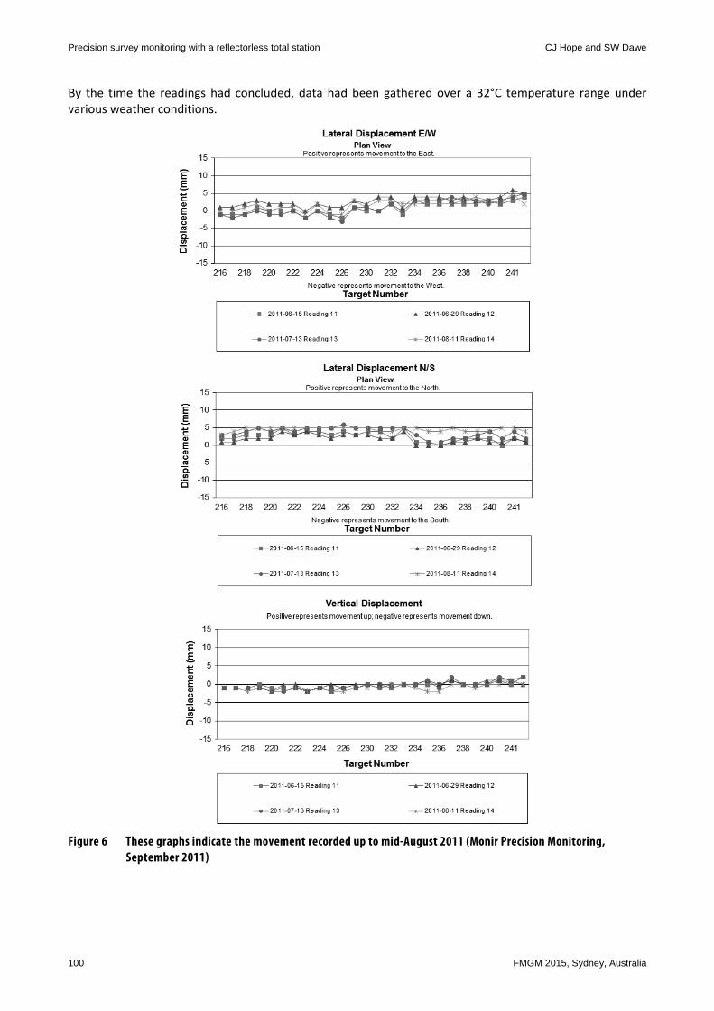
By the time the readings had concluded, data had been gathered over a 32°C temperature range under various weather conditions.
Figure 6 These graphs indicate the movement recorded up to mid-August 2011 (Monir Precision Monitoring, September 2011)

Case studies
FMGM 2015, Sydney, Australia 101
This was an interesting job from the point of view of taking the background readings, as this is normally done only once and then the monitoring readings start. The results above showed only small movements from the seasonal changes with good repeatability.
Figure 7 Monitoring points on the Head-House (Monir Precision Monitoring, February 2011)
6.3 Brampton Civic Centre
The Brampton Civic Centre project was an expansion of the Brampton Civic Centre onto a large piece of vacant land, across the road from the existing centre; however, some of the neighbouring properties were unreceptive to the project and would not agree to tie‐backs or to having monitoring points installed on their buildings. As a way to work around the lack of monitoring targets, reflectorless points were used on multiple buildings to track movements.
Figure 8 Monitoring locations on some of the unreceptive buildings (Monir Precision Monitoring, February 2012)
The surfaces above were weathered stucco with some moderately flat areas amongst the rougher portions. There was some background scatter included in the readings but the trends of the movements were still easily recognised.

Precision survey monitoring with a reflectorless total station CJ Hope and SW Dawe
102 FMGM 2015, Sydney, Australia
Figure 9 These graphs show reflectorless measurements to points on unreceptive buildings (Monir Precision Monitoring, February 2012)
Case studies
FMGM 2015, Sydney, Australia 103
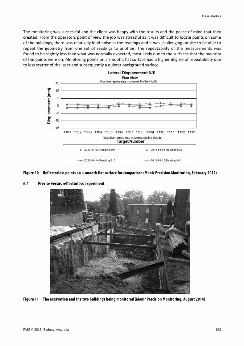
The monitoring was successful and the client was happy with the results and the peace of mind that they created. From the operators point of view the job was stressful as it was difficult to locate points on some of the buildings, there was relatively loud noise in the readings and it was challenging on site to be able to repeat the geometry from one set of readings to another. The repeatability of the measurements was found to be slightly less than what was normally expected, most likely due to the surfaces that the majority of the points were on. Monitoring points on a smooth, flat surface had a higher degree of repeatability due to less scatter of the laser and subsequently a quieter background surface.
Figure 10 Reflectorless points on a smooth flat surface for comparison (Monir Precision Monitoring, February 2012)
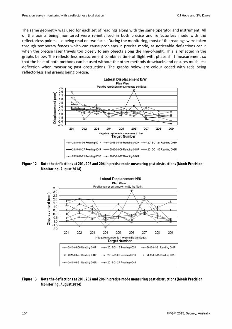
6.4 Precise versus reflectorless experiment
Figure 11 The excavation and the two buildings being monitored (Monir Precision Monitoring, August 2014)
Precision survey monitoring with a reflectorless total station CJ Hope and SW Dawe
104 FMGM 2015, Sydney, Australia
The same geometry was used for each set of readings along with the same operator and instrument. All of the points being monitored were re‐initialised in both precise and reflectorless mode with the reflectorless points also being read on two faces. During the monitoring, most of the readings were taken through temporary fences which can cause problems in precise mode, as noticeable deflections occur when the precise laser travels too closely to any objects along the line‐of‐sight. This is reflected in the graphs below. The reflectorless measurement combines time of flight with phase shift measurement so that the best of both methods can be used without the other methods drawbacks and ensures much less deflection when measuring past obstructions. The graphs below are colour coded with reds being reflectorless and greens being precise.
Figure 12 Note the deflections at 201, 202 and 206 in precise mode measuring past obstructions (Monir Precision Monitoring, August 2014)
Figure 13 Note the deflections at 201, 202 and 206 in precise mode measuring past obstructions (Monir Precision Monitoring, August 2014)
Case studies
FMGM 2015, Sydney, Australia 105
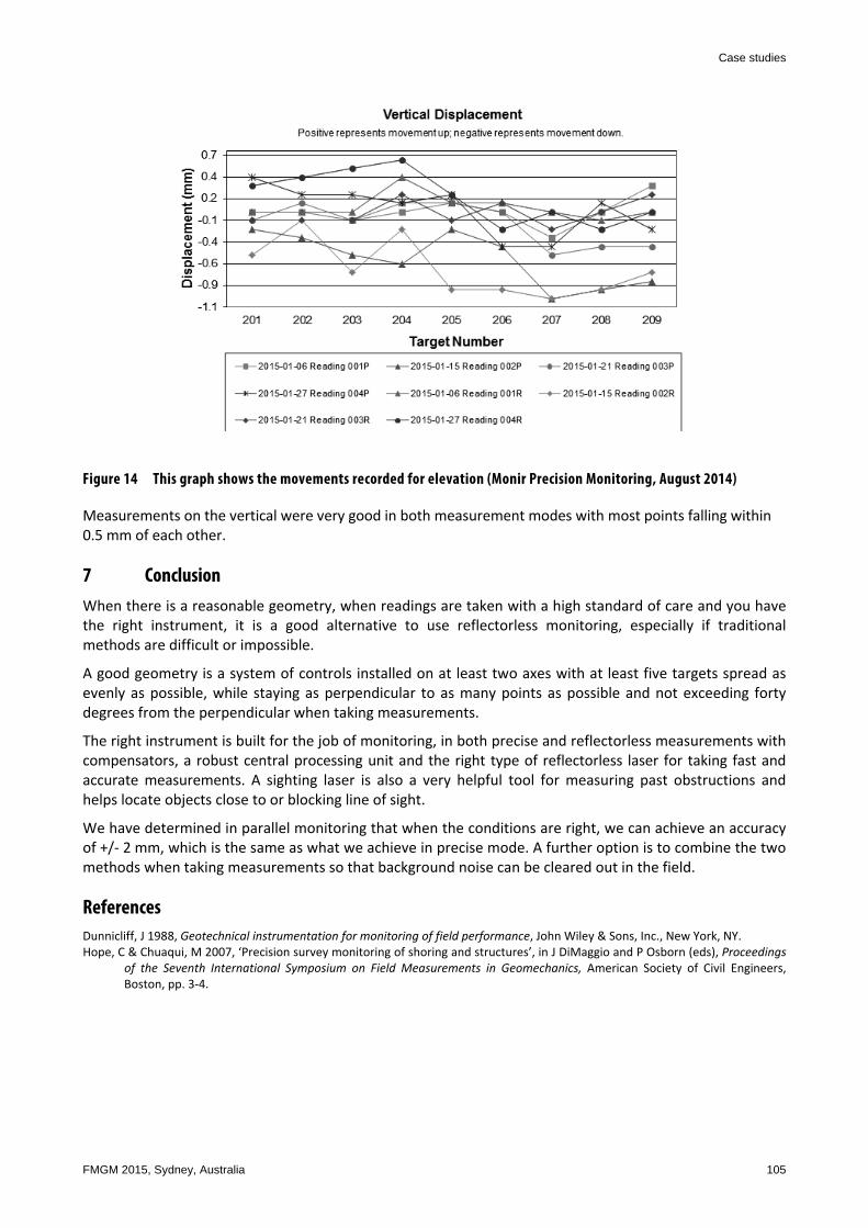
Figure 14 This graph shows the movements recorded for elevation (Monir Precision Monitoring, August 2014)
Measurements on the vertical were very good in both measurement modes with most points falling within 0.5 mm of each other.
7 Conclusion When there is a reasonable geometry, when readings are taken with a high standard of care and you have the right instrument, it is a good alternative to use reflectorless monitoring, especially if traditional methods are difficult or impossible.
A good geometry is a system of controls installed on at least two axes with at least five targets spread as evenly as possible, while staying as perpendicular to as many points as possible and not exceeding forty degrees from the perpendicular when taking measurements.
The right instrument is built for the job of monitoring, in both precise and reflectorless measurements with compensators, a robust central processing unit and the right type of reflectorless laser for taking fast and accurate measurements. A sighting laser is also a very helpful tool for measuring past obstructions and helps locate objects close to or blocking line of sight.
We have determined in parallel monitoring that when the conditions are right, we can achieve an accuracy of +/‐ 2 mm, which is the same as what we achieve in precise mode. A further option is to combine the two methods when taking measurements so that background noise can be cleared out in the field.
References Dunnicliff, J 1988, Geotechnical instrumentation for monitoring of field performance, John Wiley & Sons, Inc., New York, NY. Hope, C & Chuaqui, M 2007, ‘Precision survey monitoring of shoring and structures’, in J DiMaggio and P Osborn (eds), Proceedings
of the Seventh International Symposium on Field Measurements in Geomechanics, American Society of Civil Engineers, Boston, pp. 3‐4.

Precision survey monitoring with a reflectorless total station CJ Hope and SW Dawe
106 FMGM 2015, Sydney, Australia