Embed Size (px)
Citation preview

Initial Print Date: 03/11
Table of Contents
Subject Page
Introduction . . . . . . . . . . . . . . . . . . . . . . . . . . . . . . . . . . . . . . . . . . . . . .5Cooling System N54 . . . . . . . . . . . . . . . . . . . . . . . . . . . . . . . . . . . . . . . . . . . .5
Layout . . . . . . . . . . . . . . . . . . . . . . . . . . . . . . . . . . . . . . . . . . . . . . . . . . . . .7Radiator . . . . . . . . . . . . . . . . . . . . . . . . . . . . . . . . . . . . . . . . . . . . . . . . . . . . .7Electric Coolant Pump (EWP) . . . . . . . . . . . . . . . . . . . . . . . . . . . . . . . . .8
Cooling System N55 . . . . . . . . . . . . . . . . . . . . . . . . . . . . . . . . . . . . . . . . . .10Engine Cooling Circuit Diagram (N55) . . . . . . . . . . . . . . . . . . . . . . . . .14
Cooling System N63 . . . . . . . . . . . . . . . . . . . . . . . . . . . . . . . . . . . . . . . . . .16Coolant Pumps N63 . . . . . . . . . . . . . . . . . . . . . . . . . . . . . . . . . . . . . . . .18
Main coolant pump . . . . . . . . . . . . . . . . . . . . . . . . . . . . . . . . . . . . . .18Auxiliary coolant pump for turbocharger cooling . . . . . . . . . . . . .18
System Protection . . . . . . . . . . . . . . . . . . . . . . . . . . . . . . . . . . . . . . . . . .18Cooling System N74 . . . . . . . . . . . . . . . . . . . . . . . . . . . . . . . . . . . . . . . . . .19
Coolant Pumps N74 . . . . . . . . . . . . . . . . . . . . . . . . . . . . . . . . . . . . . . . .20Main coolant pump . . . . . . . . . . . . . . . . . . . . . . . . . . . . . . . . . . . . . .20Auxiliary water pump for exhaust turbochargers . . . . . . . . . . . . .20
Expansion Tank . . . . . . . . . . . . . . . . . . . . . . . . . . . . . . . . . . . . . . . . . . . .21
Charge Air Cooling . . . . . . . . . . . . . . . . . . . . . . . . . . . . . . . . . . . . . . .23Charge Air Cooling N63 . . . . . . . . . . . . . . . . . . . . . . . . . . . . . . . . . . . . . . . .23
Intercoolers . . . . . . . . . . . . . . . . . . . . . . . . . . . . . . . . . . . . . . . . . . . . . . . .24Electric Coolant Pump . . . . . . . . . . . . . . . . . . . . . . . . . . . . . . . . . . . . . . .24Venting . . . . . . . . . . . . . . . . . . . . . . . . . . . . . . . . . . . . . . . . . . . . . . . . . . . .24
Charge Air Cooling N74 . . . . . . . . . . . . . . . . . . . . . . . . . . . . . . . . . . . . . . . .24Auxiliary Coolant Pump for Charge Air Cooling . . . . . . . . . . . . . . . . .24Charge-air Cooler . . . . . . . . . . . . . . . . . . . . . . . . . . . . . . . . . . . . . . . . . . .24
Engine Oil Cooling . . . . . . . . . . . . . . . . . . . . . . . . . . . . . . . . . . . . . . . .27Engine Oil Cooling (N54) . . . . . . . . . . . . . . . . . . . . . . . . . . . . . . . . . . . . . . .27
Oil Pump and Pressure Control (N55) . . . . . . . . . . . . . . . . . . . . . . . . .28Oil Pressure . . . . . . . . . . . . . . . . . . . . . . . . . . . . . . . . . . . . . . . . . . . . . . . .31Oil Pressure Sensor . . . . . . . . . . . . . . . . . . . . . . . . . . . . . . . . . . . . . . . . .31
Electronic Oil Condition Monitoring . . . . . . . . . . . . . . . . . . . . . . . . . . . . . .31Function of the Oil Condition Sensor . . . . . . . . . . . . . . . . . . . . . . . . . .33Faults/Evaluation . . . . . . . . . . . . . . . . . . . . . . . . . . . . . . . . . . . . . . . . . . . .33
Cooling Systems
Revision Date:
meeknet.co.uk/e64
Subject Page
Electronic Oil Level Indicator . . . . . . . . . . . . . . . . . . . . . . . . . . . . . . . . . . .34Static Oil Level Measurement at Engine OFF . . . . . . . . . . . . . . . . .34Dynamic Oil Level Measurement During Vehicle Operation . . . . . .36Display Options . . . . . . . . . . . . . . . . . . . . . . . . . . . . . . . . . . . . . . . . . . . . .37
Heat Management . . . . . . . . . . . . . . . . . . . . . . . . . . . . . . . . . . . . . . . .39Intelligent Heat Management Options . . . . . . . . . . . . . . . . . . . . . . . . . . .41System Protection . . . . . . . . . . . . . . . . . . . . . . . . . . . . . . . . . . . . . . . . . . . . .42
Measures and Displays for Engine Oil Temperature . . . . . . . . . . . .42Measures and Displays for Coolant Temperature . . . . . . . . . . . . . . .43

Subject Page
BLANKPAGE
4Cooling Systems
Cooling Systems
Model: All
Production: All
After completion of this module you will be able to:
• Understand the operation of the main components in the cooling system
• Understand the different charge air cooling systems
• Understand the principles of Heat Management
• Understand the difference between static and dynamic oil measurement
• List the advantages of EWP
5Cooling Systems
Cooling System N54
The cooling system of the N54 engine consists of a radiator circuit and an isolated oil cooling circuit. The fact that there is an isolated oil-cooling circuit ensures that heatis not introduced via the engine oil into the engine's coolant system.
There is a significantly greater quantity of heat on account of this engine's increasedpower of 75.5 kW/l in comparison with the N52.
This boundary condition is satisfied by the engine cooling system with its increased performance. This increase in power was to be realized in spite of some factors lessadvantageous to cooling.
Factors to be mentioned here are:
• Approximately 15% less flow area is available on account of the intercooler locatedbelow the radiator.
• The already small amount of space provided by the engine compartment is furtherlimited by the accommodation of further components.
• Because the exhaust turbochargers are cooled by the coolant, an additional quanti-ty of heat is introduced into the system via these turbochargers.
Measures for increasing cooling-system performance:
• Coolant pump with increased power 400 W/9000 l/h
• Separation of water and engine-oil cooling
• Radiator with increased power
• Electric fan with increased power 600W for all gearbox variants
Charge-air cooling is described in the section dealing with air-intake ducting.
Introduction

6Cooling Systems
N54 Cooling System
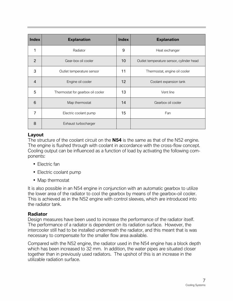
Layout The structure of the coolant circuit on the N54 is the same as that of the N52 engine.The engine is flushed through with coolant in accordance with the cross-flow concept.Cooling output can be influenced as a function of load by activating the following com-ponents:
• Electric fan
• Electric coolant pump
• Map thermostat
It is also possible in an N54 engine in conjunction with an automatic gearbox to utilizethe lower area of the radiator to cool the gearbox by means of the gearbox-oil cooler.This is achieved as in the N52 engine with control sleeves, which are introduced intothe radiator tank.
RadiatorDesign measures have been used to increase the performance of the radiator itself. The performance of a radiator is dependent on its radiation surface. However, the intercooler still had to be installed underneath the radiator, and this meant that is was necessary to compensate for the smaller flow area available.
Compared with the N52 engine, the radiator used in the N54 engine has a block depthwhich has been increased to 32 mm. In addition, the water pipes are situated closertogether than in previously used radiators. The upshot of this is an increase in the utilizable radiation surface.
7Cooling Systems
Index Explanation Index Explanation
1 Radiator 9 Heat exchanger
2 Gear-box oil cooler 10 Outlet temperature sensor, cylinder head
3 Outlet temperature sensor 11 Thermostat, engine oil cooler
4 Engine oil cooler 12 Coolant expansion tank
5 Thermostat for gearbox oil cooler 13 Vent line
6 Map thermostat 14 Gearbox oil cooler
7 Electric coolant pump 15 Fan
8 Exhaust turbocharger

8Cooling Systems
Electric Coolant Pump (EWP)The coolant pump of the N54 engine is an electrically driven centrifugal pump with apower output of 400W and a maximum flow rate of 9000 l/h. This represents a signifi-cant increase in power of the electric coolant pump used in the N52 engine, which hasa power output of 200 W and a maximum flow rate of 7000 l/h.
The power of the electric wet-rotor motor is electronically controlled by the electronicmodule (3) in the pump. The electronic module is connected via the bit-serial datainterface (BSD) to the ECM engine control unit.
The engine control unit uses the engine load, the operating mode and the data from thetemperature sensors to calculate the required cooling output. Based on this data, theengine control unit issues the corresponding command to the electric coolant pump.
The electric coolant pump regulates its speed in accordance with this command. The system coolant flows through the motor of the coolant pump, thus cooling boththe motor as well as the electronic module. The coolant lubricates the bearings of the electric coolant pump.
The same rules apply to all Electric Coolant Pumps (EWP). The pumpmust be filled with coolant when removed for service to prevent anycorrosion. Also, the pump impeller must be turned by hand beforeinstallation to ensure the pump is not seized.
Index Explanation Index Explanation
1 Pump 3 Electronics for coolant pump
2 Motor
9Cooling Systems
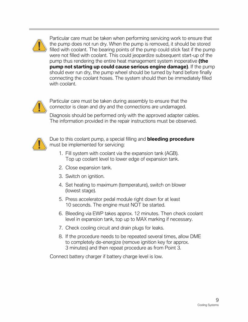
Particular�care�must�be�taken�when�performing�servicing�work�to�ensure�thatthe�pump�does�not�run�dry.�When�the�pump�is�removed,�it�should�be�storedfilled�with�coolant.�The�bearing�points�of�the�pump�could�stick�fast�if�the�pumpwere�not�filled�with�coolant.�This�could�jeopardize�subsequent�start-up�of�thepump�thus�rendering�the�entire�heat�management�system�inoperative�(thepump not starting up could cause serious engine damage).�If�the�pumpshould�ever�run�dry,�the�pump�wheel�should�be�turned�by�hand�before�finallyconnecting�the�coolant�hoses.�The�system�should�then�be�immediately�filledwith�coolant.
Particular�care�must�be�taken�during�assembly�to�ensure�that�theconnector�is�clean�and�dry�and�the�connections�are�undamaged.
Diagnosis�should�be�performed�only�with�the�approved�adapter�cables.The�information�provided�in�the�repair�instructions�must�be�observed.
Due to this coolant pump, a special filling and bleeding proceduremust be implemented for servicing:
1. Fill system with coolant via the expansion tank (AGB).Top up coolant level to lower edge of expansion tank.
2. Close expansion tank.
3. Switch on ignition.
4. Set heating to maximum (temperature), switch on blower(lowest stage).
5. Press accelerator pedal module right down for at least10 seconds. The engine must NOT be started.
6. Bleeding via EWP takes approx. 12 minutes. Then check coolantlevel in expansion tank, top up to MAX marking if necessary.
7. Check cooling circuit and drain plugs for leaks.
8. If the procedure needs to be repeated several times, allow DMEto completely de-energize (remove ignition key for approx.3 minutes) and then repeat procedure as from Point 3.
Connect�battery�charger�if�battery�charge�level�is�low.

Cooling System N55
The cooling system of the N55 is enhanced with additional oil cooling.
Two different types of oil cooling systems are used depending on the model and appli-cation. In the “hot climate” version, heat transfer from the engine oil to the enginecoolant is avoided by separating the oil cooler from the engine coolant circuit. The otherversion uses an auxiliary radiator in combination with an oil to coolant heat exchangerbolted to the oil filter housing. The auxiliary radiator enhances cooling efficiency byadding surface area to the cooling system.
10Cooling Systems
N55 Cooling System
11Cooling Systems
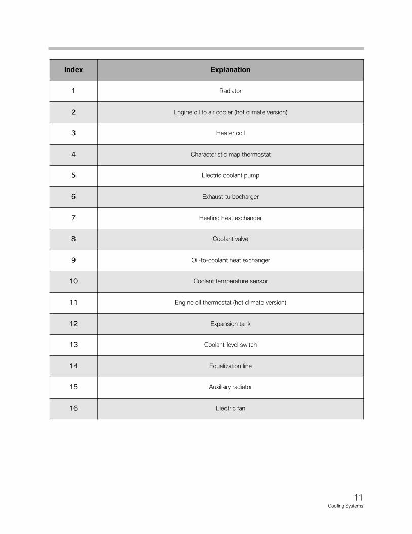
Index Explanation
1 Radiator
2 Engine oil to air cooler (hot climate version)
3 Heater coil
4 Characteristic map thermostat
5 Electric coolant pump
6 Exhaust turbocharger
7 Heating heat exchanger
8 Coolant valve
9 Oil-to-coolant heat exchanger
10 Coolant temperature sensor
11 Engine oil thermostat (hot climate version)
12 Expansion tank
13 Coolant level switch
14 Equalization line
15 Auxiliary radiator
16 Electric fan
12Cooling Systems
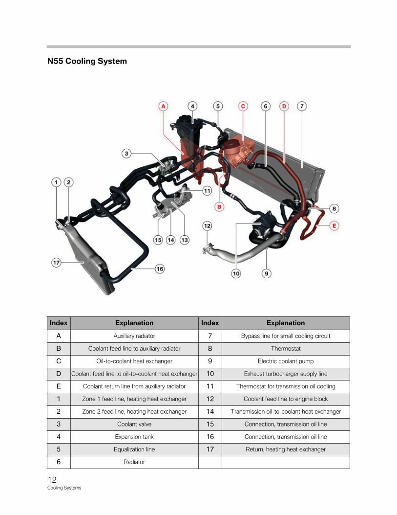
Index Explanation Index Explanation
A Auxiliary radiator 7 Bypass line for small cooling circuit
B Coolant feed line to auxiliary radiator 8 Thermostat
C Oil-to-coolant heat exchanger 9 Electric coolant pump
D Coolant feed line to oil-to-coolant heat exchanger 10 Exhaust turbocharger supply line
E Coolant return line from auxiliary radiator 11 Thermostat for transmission oil cooling
1 Zone 1 feed line, heating heat exchanger 12 Coolant feed line to engine block
2 Zone 2 feed line, heating heat exchanger 14 Transmission oil-to-coolant heat exchanger
3 Coolant valve 15 Connection, transmission oil line
4 Expansion tank 16 Connection, transmission oil line
5 Equalization line 17 Return, heating heat exchanger
6 Radiator
N55 Cooling System
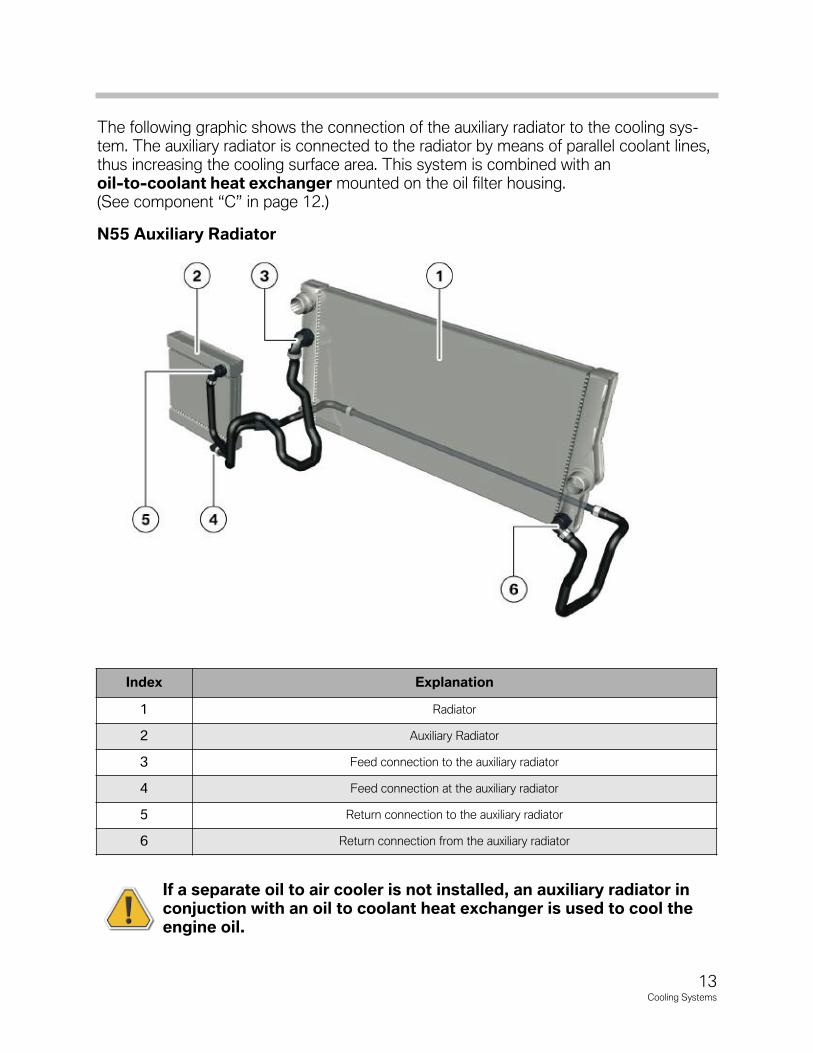
The�following�graphic�shows�the�connection�of�the�auxiliary�radiator�to�the�cooling�sys-tem.�The�auxiliary�radiator�is�connected�to�the�radiator�by�means�of�parallel�coolant�lines,thus�increasing�the�cooling�surface�area.�This�system�is�combined�with�anoil-to-coolant heat exchanger mounted�on�the�oil�filter�housing.(See�component�“C”�in�page�12.)
If a separate oil to air cooler is not installed, an auxiliary radiator in conjuction with an oil to coolant heat exchanger is used to cool theengine oil.
13Cooling Systems
Index Explanation
1 Radiator
2 Auxiliary�Radiator
3 Feed�connection�to�the�auxiliary�radiator
4 Feed�connection�at�the�auxiliary�radiator
5 Return�connection�to�the�auxiliary�radiator
6 Return�connection�from�the�auxiliary�radiator
N55 Auxiliary Radiator
14Cooling Systems
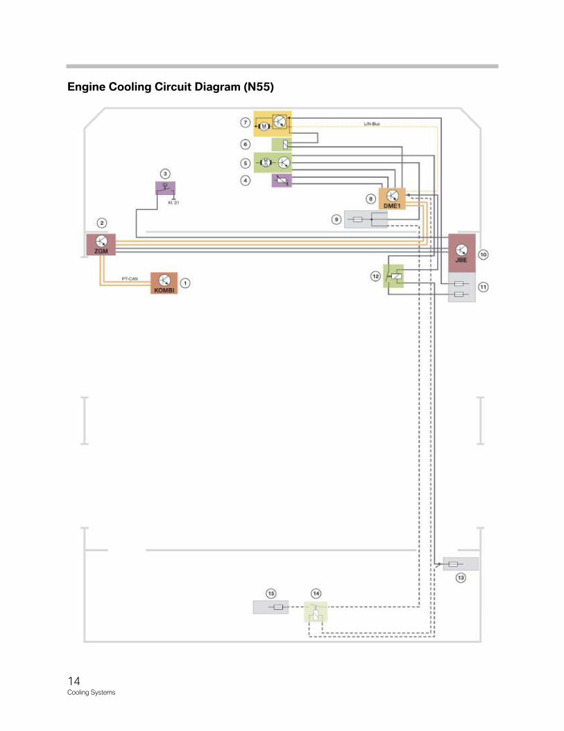
Engine Cooling Circuit Diagram (N55)
15Cooling Systems
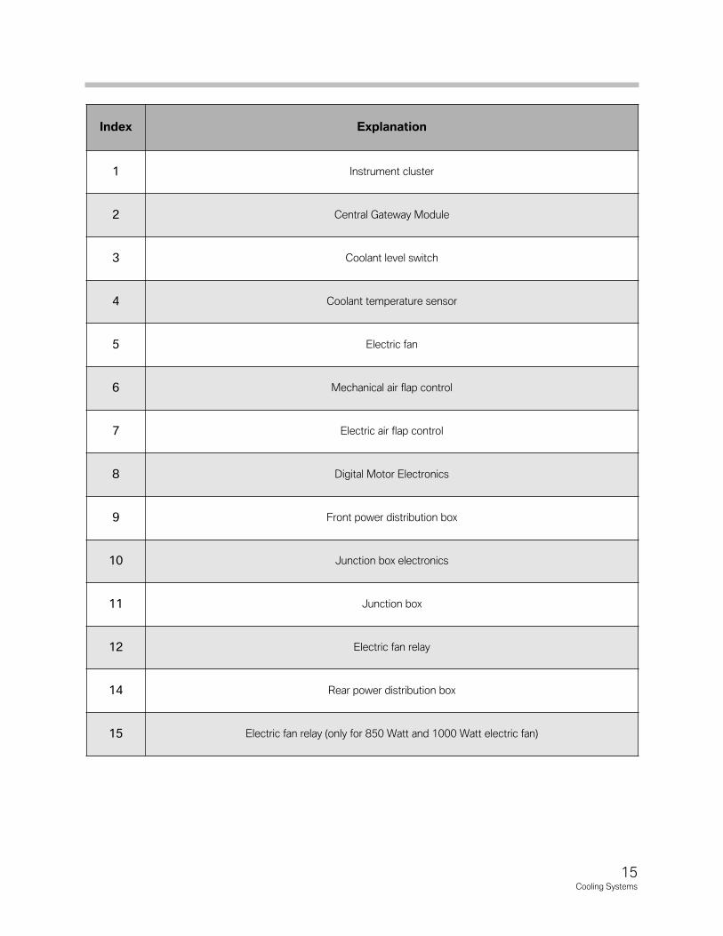
Index Explanation
1 Instrument cluster
2 Central Gateway Module
3 Coolant level switch
4 Coolant temperature sensor
5 Electric fan
6 Mechanical air flap control
7 Electric air flap control
8 Digital Motor Electronics
9 Front power distribution box
10 Junction box electronics
11 Junction box
12 Electric fan relay
14 Rear power distribution box
15 Electric fan relay (only for 850 Watt and 1000 Watt electric fan)
16Cooling Systems
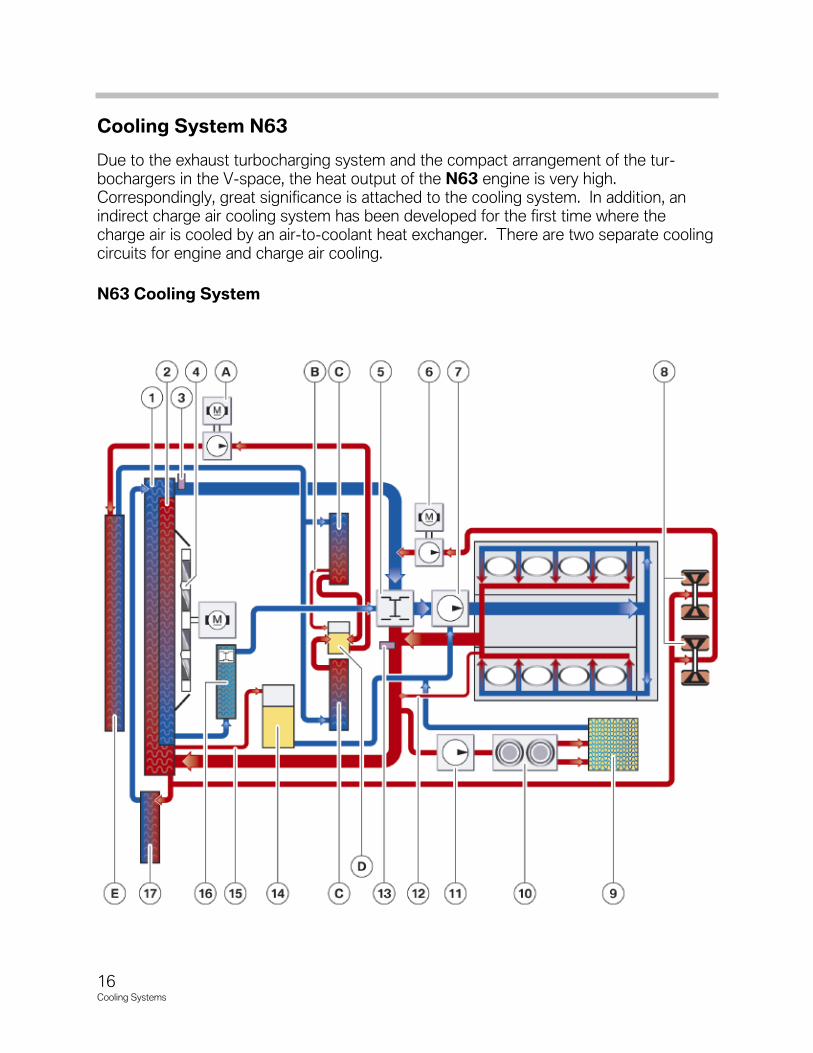
Cooling System N63
Due to the exhaust turbocharging system and the compact arrangement of the tur-bochargers in the V-space, the heat output of the N63 engine is very high.Correspondingly, great significance is attached to the cooling system. In addition, anindirect charge air cooling system has been developed for the first time where thecharge air is cooled by an air-to-coolant heat exchanger. There are two separate coolingcircuits for engine and charge air cooling.
N63 Cooling System
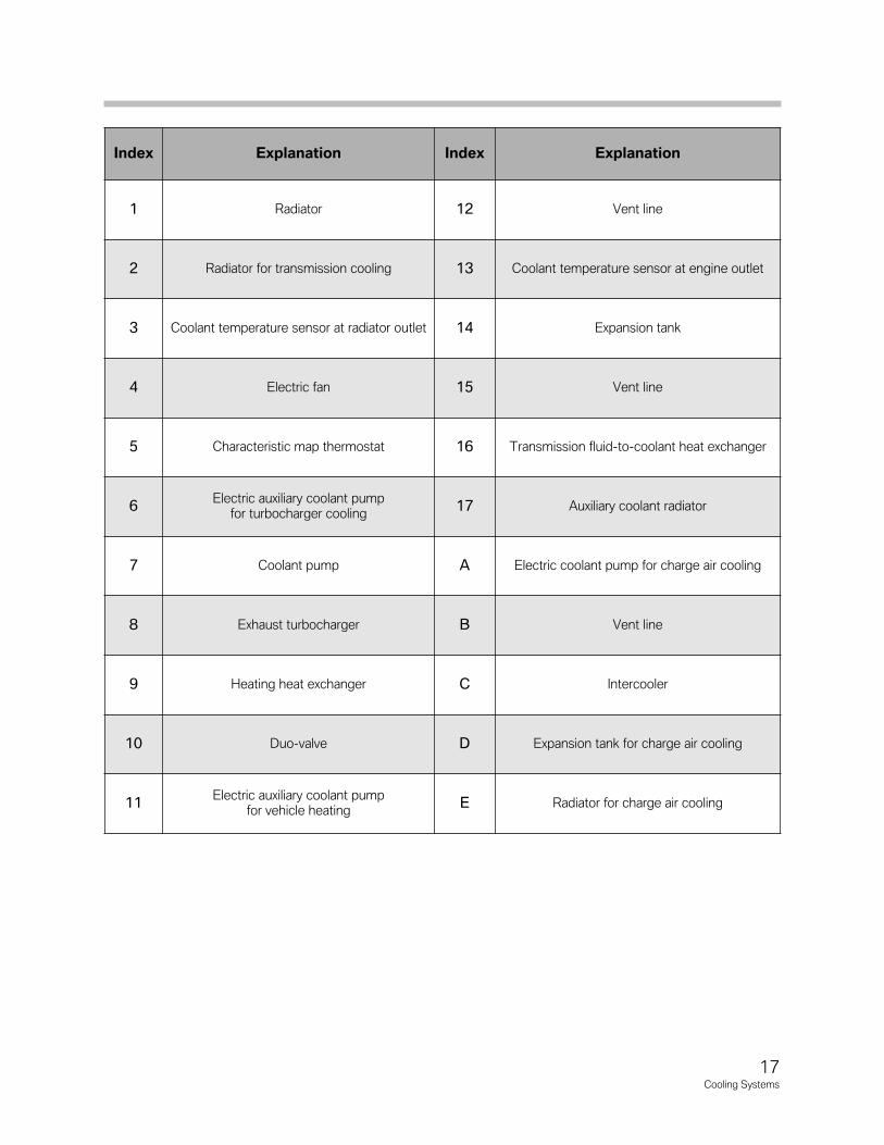
17Cooling Systems
Index Explanation Index Explanation
1 Radiator 12 Vent line
2 Radiator for transmission cooling 13 Coolant temperature sensor at engine outlet
3 Coolant temperature sensor at radiator outlet 14 Expansion tank
4 Electric fan 15 Vent line
5 Characteristic map thermostat 16 Transmission fluid-to-coolant heat exchanger
6Electric auxiliary coolant pump
for turbocharger cooling 17 Auxiliary coolant radiator
7 Coolant pump A Electric coolant pump for charge air cooling
8 Exhaust turbocharger B Vent line
9 Heating heat exchanger C Intercooler
10 Duo-valve D Expansion tank for charge air cooling
11Electric auxiliary coolant pump
for vehicle heating E Radiator for charge air cooling

The engine cooling system undertakes the classic task of carrying heat away from theengine and maintaining a defined operating temperature as constant as possible. As onthe N54 engine, the two turbochargers are also cooled.
Coolant Pumps N63
Main coolant pump
The N63 engine features a conventional coolant pump that is driven by the belt drive.This pump cannot be used to continue cooling the turbochargers after the engine hasbeen shut down. For this reason the N63 is also equipped with an auxiliary coolantpump.
Auxiliary coolant pump for turbocharger cooling
The electric coolant pump on the N54 engine features an after-running function to carryaway the heat build-up from the turbochargers after the engine has been shut down.
For this function, the N63 engine is equipped with an additional electrically operatedcoolant pump with an output of 20 W. This pump is also used during engine operation toassist turbocharger cooling.
The auxiliary electric coolant pump cuts in, taking the following factors into consideration:
• Coolant temperature at engine outlet
• Engine oil temperature
• Injected fuel quantity
The heat input into the engine is calculated based on the injected fuel quantity. Thisfunction is similar to the heat management function on 6-cylinder engines.
The after-running period of the auxiliary electric coolant pump can extend up to 30 min-utes. The electric fan also cuts in to improve the cooling effect.
As in previous systems, the electric fan runs for a maximumof 11 minutes, however, it now operates more frequently.
System ProtectionAs on the N54 engine, the N63 in the event of the coolant or engine oil being subject toexcessive temperatures, certain functions in the vehicle are influenced in such a way thatmore energy is made available to the engine cooling system, i.e. temperature increasingloads are avoided.
18Cooling Systems

19Cooling Systems
Cooling System N74
Because of the turbocharging and indirect charge air cooling, the N74 engine has thesame cooling requirements as the N63 engine. Consequently it too has two separatecooling circuits. One is for cooling the engine and exhaust turbochargers, the other is forcharge air cooling and for cooling the two engine control units.
The engine cooling system performs the task of drawing heat off the engine and maintaining the operating temperature as constant as possible. As on the N54 and N63engines, the two exhaust turbochargers are also cooled.
On the N74 engine, the coolant passages have been integrated mainly in the engineblock. Optimizations to the engine cooling circuit have enabled a significant reduction inthe coolant quantity for the bypass mode, thus shortening the warm-up phase.
The coolant feed line downstream of the coolant pump is routed directly beside theengines main oil duct. The oil in the main oil duct flows in the opposite direction to thecoolant. This enhances the heat exchange between the two media, and has a positiveeffect on the engine oil temperature. The overall cooling effect is comparable with thatof an engine oil-coolant heat exchanger.
The coolant passages in the cylinder heads are similar to the N63 engine. The coolantflows through the cylinder heads diagonally from the outside to the inside, whereby itflows in at the rear (outside) and flows out at the front (inside). This is also known as diagonal cooling.
As on the N63 engine, an additional electric coolant pump is usedwhich supplies the bearings of the exhaust turbochargers withcoolant.
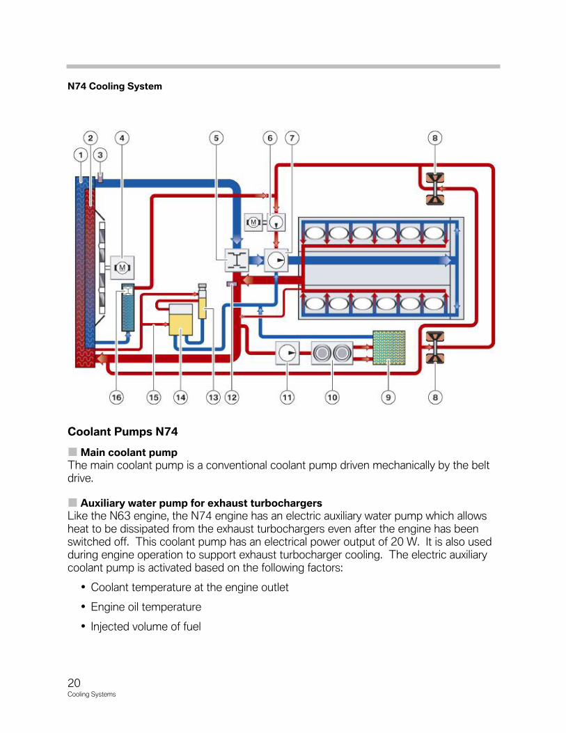
Coolant Pumps N74
Main coolant pump
The main coolant pump is a conventional coolant pump driven mechanically by the beltdrive.
Auxiliary water pump for exhaust turbochargers
Like the N63 engine, the N74 engine has an electric auxiliary water pump which allowsheat to be dissipated from the exhaust turbochargers even after the engine has beenswitched off. This coolant pump has an electrical power output of 20 W. It is also usedduring engine operation to support exhaust turbocharger cooling. The electric auxiliarycoolant pump is activated based on the following factors:
• Coolant temperature at the engine outlet
• Engine oil temperature
• Injected volume of fuel
20Cooling Systems
N74 Cooling System
21Cooling Systems
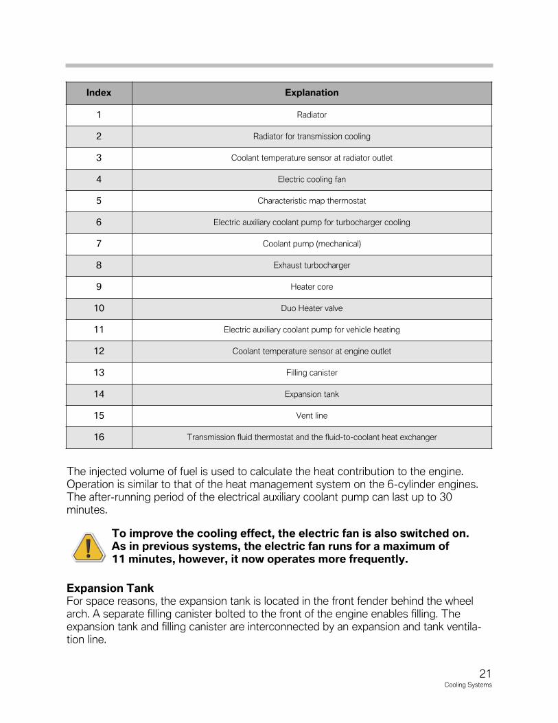
The injected volume of fuel is used to calculate the heat contribution to the engine.Operation is similar to that of the heat management system on the 6-cylinder engines.The after-running period of the electrical auxiliary coolant pump can last up to 30 minutes.
To improve the cooling effect, the electric fan is also switched on.As in previous systems, the electric fan runs for a maximum of11 minutes, however, it now operates more frequently.
Expansion TankFor space reasons, the expansion tank is located in the front fender behind the wheelarch. A separate filling canister bolted to the front of the engine enables filling. Theexpansion tank and filling canister are interconnected by an expansion and tank ventila-tion line.
Index Explanation
1 Radiator
2 Radiator for transmission cooling
3 Coolant temperature sensor at radiator outlet
4 Electric cooling fan
5 Characteristic map thermostat
6 Electric auxiliary coolant pump for turbocharger cooling
7 Coolant pump (mechanical)
8 Exhaust turbocharger
9 Heater core
10 Duo Heater valve
11 Electric auxiliary coolant pump for vehicle heating
12 Coolant temperature sensor at engine outlet
13 Filling canister
14 Expansion tank
15 Vent line
16 Transmission fluid thermostat and the fluid-to-coolant heat exchanger

22Cooling Systems
NOTESPAGE
23Cooling Systems
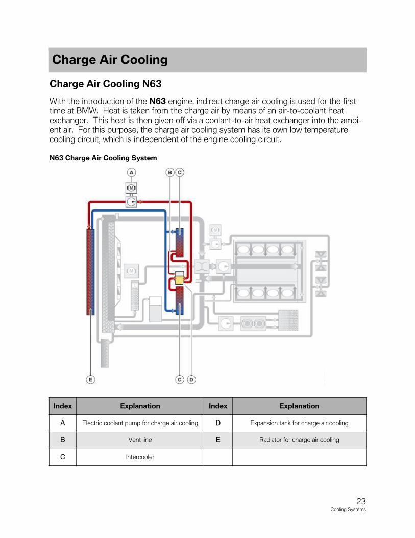
Charge Air Cooling N63
With the introduction of the N63 engine, indirect charge air cooling is used for the firsttime at BMW. Heat is taken from the charge air by means of an air-to-coolant heatexchanger. This heat is then given off via a coolant-to-air heat exchanger into the ambi-ent air. For this purpose, the charge air cooling system has its own low temperaturecooling circuit, which is independent of the engine cooling circuit.
Index Explanation Index Explanation
A Electric coolant pump for charge air cooling D Expansion tank for charge air cooling
B Vent line E Radiator for charge air cooling
C Intercooler
N63 Charge Air Cooling System
Charge Air Cooling

24Cooling Systems
IntercoolersThe intercoolers are installed on the end faces of the cylinder heads. They operate inaccordance with the counterflow principle and cool the charge air by up to 80°C.
Electric Coolant PumpThe coolant circuit for charge air coolant is operated with a 50 W pump. This pumpdoes not run automatically when the engine is turned on.
Pump actuation depends on the following values:
• Outside temperature
• Difference between charge air temperature and outside temperature
VentingA separate venting routine is provided for the purpose of venting the low-temperaturecircuit of the charge air cooling system. This venting is initiated in the same way as forthe cooling circuit on 6-cylinder engines.
The venting test module can be found in the “Service Functions” section of the diagnos-tic program.
Charge Air Cooling N74
The N63 engine was the first BMW engine to use indirect charge air cooling; this hasnow also been adopted for the N74 engine. The heat is extracted from the charge air bymeans of an air to coolant heat exchanger. This heat is then released to the ambient airacross a coolant to air heat exchanger. To achieve this, the charge air cooling has its ownlow-temperature cooling circuit. This is independent of the engine cooling circuit.
Auxiliary Coolant Pump for Charge Air CoolingThe cooling circuit for charge air cooling is operated with a 50 W pump. It does not runautomatically when the engine is switched on.
The following parameters are used for the auxiliary pump activation:
• Outside temperature
• Difference between charge-air temperature and outside temperature.
Charge-air CoolerThe charge air coolers (intercoolers) are attached to the intake system near the rear ofthe cylinder heads. They enable efficient cooling of the charge air by extracting heatenergy from the air charge and carrying it away to the coolant to air heat exchangerlocated in the front of the vehicle.

25Cooling Systems
Index Explanation
1 Radiator for charge air cooling
2 Electric coolant pump for charge air cooling
3 Engine control unit
4 Expansion tank
5 Charge-air cooler
N74 Charge Air Cooling System

26Cooling Systems
NOTESPAGE

27Cooling Systems
One of the main purposes of the ECM is to monitor and control the Engine-Oil Coolingwhich includes the actuation of several components. In the following pages you will find ageneric explanation on how this system works. For more detailed information pleaseaccess BMW Training Reference Manuals found on-line.
Engine Oil Cooling (N54)
The N54 engine is equipped with a high performance engine-oil cooler. The pendulum-slide pump delivers the oil from the oil sump to the oil filter. A thermostat flanged to theoil-filter housing admits the oil to the engine-oil cooler. The engine-oil cooler is locatedin the right wheel arch. The thermostat can reduce the resistance opposing the oil byopening the bypass line between the feed and return lines of the engine-oil cooler. Thisensures that the engine warms up safely and quickly.
Engine Oil Cooling
28Cooling Systems
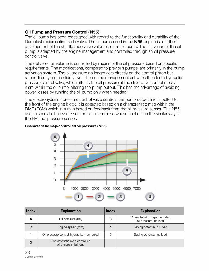
Oil�Pump�and�Pressure�Control�(N55)The�oil�pump�has�been�redesigned�with�regard�to�the�functionality�and�durability�of�theDuroplast�reciprocating�slide�valve.�The�oil�pump�used�in�the�N55 engine�is�a�furtherdevelopment�of�the�shuttle�slide�valve�volume�control�oil�pump.�The�activation�of�the�oilpump�is�adapted�by�the�engine�management�and�controlled�through�an�oil�pressure�control�valve.�
The�delivered�oil�volume�is�controlled�by�means�of�the�oil�pressure,�based�on�specificrequirements.�The�modifications,�compared�to�previous�pumps,�are�primarily�in�the�pumpactivation�system.�The�oil�pressure�no�longer�acts�directly�on�the�control�piston�butrather�directly�on�the�slide�valve.�The�engine�management�activates�the�electrohydraulic�pressure�control�valve,�which�affects�the�oil�pressure�at�the�slide�valve�control�mecha-nism�within�the�oil�pump,�altering�the�pump�output.�This�has�the�advantage�of�avoidingpower�losses�by�running�the�oil�pump�only�when�needed.
The�electrohydraulic�pressure�control�valve�controls�the�pump�output�and�is�bolted�tothe�front�of�the�engine�block.�It�is�operated�based�on�a�characteristic�map�within�theDME�(ECM)�which�in�turn�is�based�on�feedback�from�the�oil�pressure�sensor.�The�N55uses�a�special�oil�pressure�sensor�for�this�purpose�which�functions�in�the�similar�way�asthe�HPI�fuel�pressure�sensor.
Characteristic�map-controlled�oil�pressure�(N55)
Index Explanation Index Explanation
A Oil�pressure�(bar) 3Characteristic�map-controlled�
oil�pressure,�no�load
B Engine�speed�(rpm)� 4 Saving�potential,�full�load
1 Oil�pressure�control,�hydraulic/�mechanical� 5 Saving�potential,�no�load�
2Characteristic�map-controlled�
oil�pressure,�full�load
29Cooling Systems
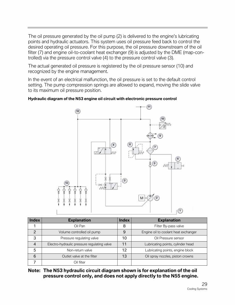
The�oil�pressure�generated�by�the�oil�pump�(2)�is�delivered�to�the�engine’s�lubricatingpoints�and�hydraulic�actuators.�This�system�uses�oil�pressure�feed�back�to�control�thedesired�operating�oil�pressure.�For�this�purpose,�the�oil�pressure�downstream�of�the�oil�filter�(7)�and�engine�oil-to-coolant�heat�exchanger�(9)�is�adjusted�by�the�DME�(map-con-trolled)�via�the�pressure�control�valve�(4)�to�the�pressure�control�valve�(3).
The�actual�generated�oil�pressure�is�registered�by�the�oil�pressure�sensor�(10)�andrecognized�by�the�engine�management.
In�the�event�of�an�electrical�malfunction,�the�oil�pressure�is�set�to�the�default�control�setting.�The�pump�compression�springs�are�allowed�to�expand,�moving�the�slide�valveto�its�maximum�oil�pressure�position.
Hydraulic�diagram�of�the�N53�engine�oil�circuit�with�electronic�pressure�control
Note: The�N53�hydraulic�circuit�diagram�shown�is�for�explanation�of�the�oilpressure�control�only,�and�does�not�apply�directly�to�the�N55�engine.
Index Explanation Index Explanation
1 Oil�Pan 8 Filter�By-pass�valve
2 Volume�controlled�oil�pump 9 Engine�oil�to�coolant�heat�exchanger�
3 Pressure�regulating�valve 10 Oil�Pressure�sensor
4 Electro-hydraulic�pressure�regulating�valve 11 Lubricating�points,�cylinder�head
5 Non-return�valve 12 Lubricating�points,�engine�block
6 Outlet�valve�at�the�filter 13 Oil�spray�nozzles,�piston�crowns
7 Oil�filter

30Cooling Systems
N55,�oil�pump�and�pressure�control�valve
Index Explanation
1 Oil�pressure�control�valve
2 Oil�pump
3 Oil�pressure�sensor
3
Oil�PressureSince�the�N55 engine�has�an�oil�pump�with�electronic�volumetric�flow�control,�it�is�nec-essary�to�measure�the�oil�pressure�precisely.�For�this�reason,�a�new�oil�pressure�sensoris�installed.�
Advantages�of�the�new�oil�pressure�sensor:
•�It�now�measures�absolute�pressure�(previous�measured�relative�pressure).
•�It�is�characteristic�map�control�in�all�speed�ranges.
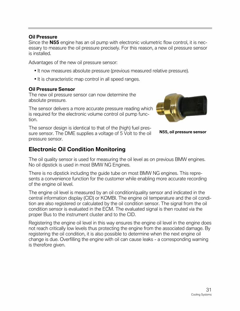
Oil�Pressure�SensorThe�new�oil�pressure�sensor�can�now�determine�theabsolute�pressure.�
The�sensor�delivers�a�more�accurate�pressure�reading�whichis�required�for�the�electronic�volume�control�oil�pump�func-tion.�
The�sensor�design�is�identical�to�that�of�the�(high)�fuel�pres-sure�sensor.�The�DME�supplies�a�voltage�of�5�Volt�to�the�oilpressure�sensor.
Electronic Oil Condition Monitoring
The�oil�quality�sensor�is�used�for�measuring�the�oil�level�as�on�previous�BMW�engines.No�oil�dipstick�is�used�in�most�BMW�NG�Engines.
There�is�no�dipstick�including�the�guide�tube�on�most�BMW�NG�engines.�This�repre-sents�a�convenience�function�for�the�customer�while�enabling�more�accurate�recordingof�the�engine�oil�level.
The�engine�oil�level�is�measured�by�an�oil�condition/quality�sensor�and�indicated�in�thecentral�information�display�(CID)�or�KOMBI.�The�engine�oil�temperature�and�the�oil�condi-tion�are�also�registered�or�calculated�by�the�oil�condition�sensor.�The�signal�from�the�oilcondition�sensor�is�evaluated�in�the�ECM.�The�evaluated�signal�is�then�routed�via�theproper�Bus�to�the�instrument�cluster�and�to�the�CID.
Registering�the�engine�oil�level�in�this�way�ensures�the�engine�oil�level�in�the�engine�doesnot�reach�critically�low�levels�thus�protecting�the�engine�from�the�associated�damage.�Byregistering�the�oil�condition,�it�is�also�possible�to�determine�when�the�next�engine�oilchange�is�due.�Overfilling�the�engine�with�oil�can�cause�leaks�-�a�corresponding�warningis�therefore�given.
31Cooling Systems
N55,�oil�pressure�sensor
32Cooling�Systems
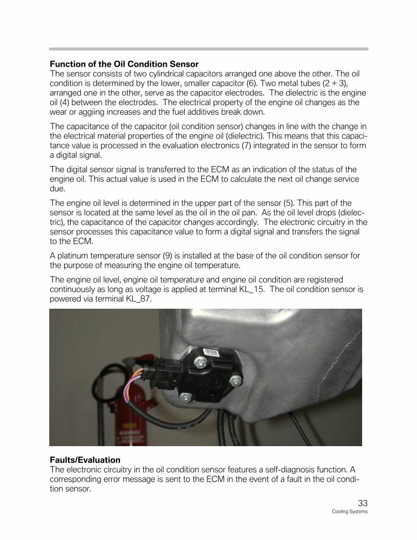
Index Explanation Index Explanation
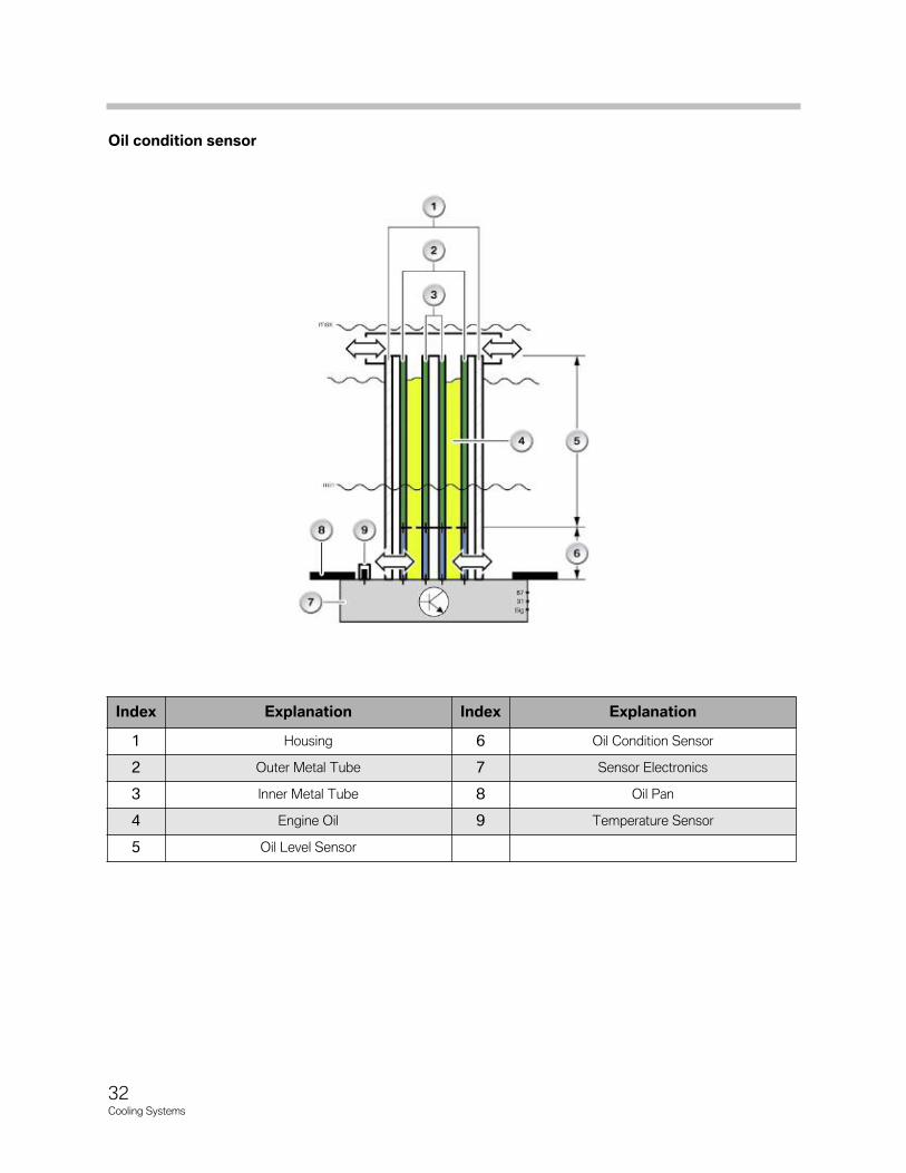
1 Housing 6 Oil�Condition�Sensor
2 Outer�Metal�Tube 7 Sensor�Electronics
3 Inner�Metal�Tube 8 Oil�Pan
4 Engine�Oil 9 Temperature�Sensor
5 Oil�Level�Sensor
Oil condition sensor
33Cooling�Systems
Function of the Oil Condition SensorThe sensor consists of two cylindrical capacitors arranged one above the other. The oilcondition is determined by the lower, smaller capacitor (6). Two metal tubes (2 + 3),arranged one in the other, serve as the capacitor electrodes. The dielectric is the engineoil (4) between the electrodes. The electrical property of the engine oil changes as thewear or aggiing increases and the fuel additives break down.
The capacitance of the capacitor (oil condition sensor) changes in line with the change inthe electrical material properties of the engine oil (dielectric). This means that this capaci-tance value is processed in the evaluation electronics (7) integrated in the sensor to forma digital signal.
The digital sensor signal is transferred to the ECM as an indication of the status of theengine oil. This actual value is used in the ECM to calculate the next oil change servicedue.
The engine oil level is determined in the upper part of the sensor (5). This part of the sensor is located at the same level as the oil in the oil pan. As the oil level drops (dielec-tric), the capacitance of the capacitor changes accordingly. The electronic circuitry in thesensor processes this capacitance value to form a digital signal and transfers the signalto the ECM.
A platinum temperature sensor (9) is installed at the base of the oil condition sensor forthe purpose of measuring the engine oil temperature.
The engine oil level, engine oil temperature and engine oil condition are registered continuously as long as voltage is applied at terminal KL_15. The oil condition sensor ispowered via terminal KL_87.
Faults/EvaluationThe electronic circuitry in the oil condition sensor features a self-diagnosis function. Acorresponding error message is sent to the ECM in the event of a fault in the oil condi-tion sensor.
34Cooling�Systems
Electronic Oil Level Indicator
The oil level is measured in two stages:
• Static oil level measurement while the vehicle is stationary
• Dynamic oil level measurement during vehicle operation
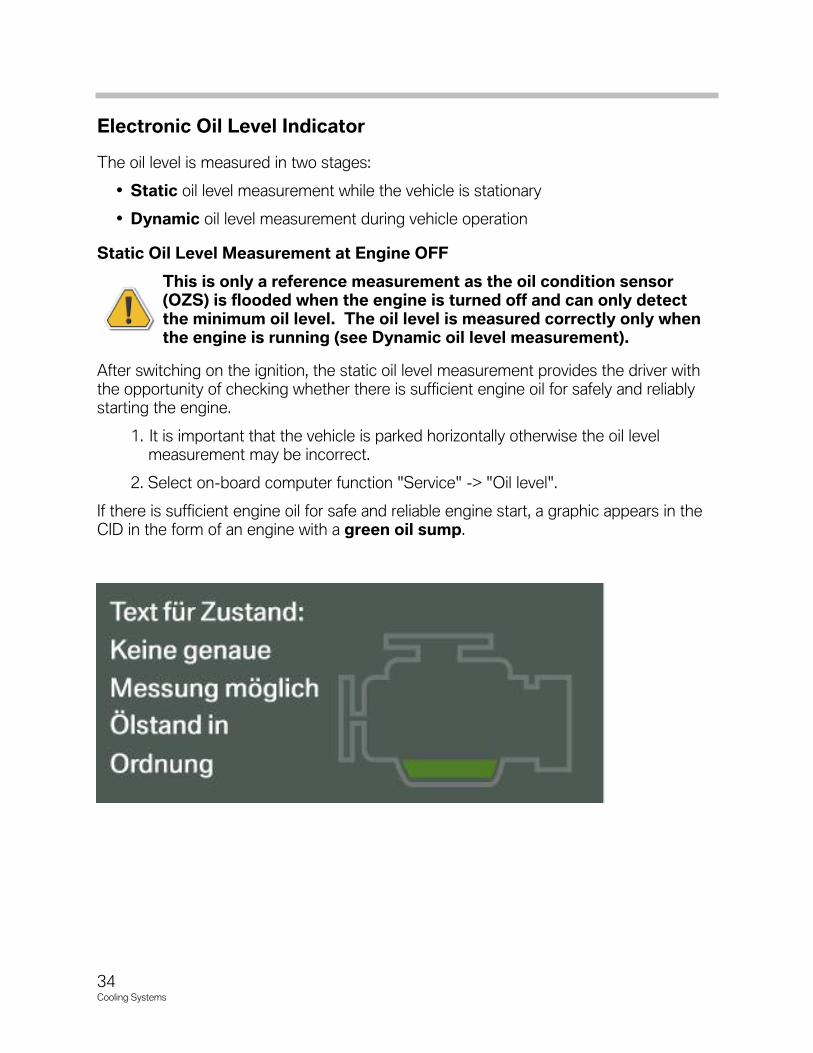
Static Oil Level Measurement at Engine OFF
This is only a reference measurement as the oil condition sensor(OZS) is flooded when the engine is turned off and can only detectthe minimum oil level. The oil level is measured correctly only whenthe engine is running (see Dynamic oil level measurement).
After switching on the ignition, the static oil level measurement provides the driver withthe opportunity of checking whether there is sufficient engine oil for safely and reliablystarting the engine.
1. It is important that the vehicle is parked horizontally otherwise the oil level measurement may be incorrect.
2. Select on-board computer function "Service" -> "Oil level".
If there is sufficient engine oil for safe and reliable engine start, a graphic appears in theCID in the form of an engine with a green oil sump.

35Cooling�Systems
If�the�oil�level�is�close�to�minimum,�thegraphic�appears�with�a�yellow oil sumpand�an�oil�dipstick�that�represents�the�lowoil�level�in�yellow.
A�top-up�request�+1�liter�additionallyappears�as�a�text�message.��The�displaywill�not�change�if�less�than�1�liter�of�oil�istopped�up.�MAX�is�indicated�only�after�top-ping�up�a�quantity�of�1�liter.
If�the�oil�level�drops�below�minimum,�thegraphic�appears�with�a�red oil sump andan�oil�dipstick�that�represents�the�low�oillevel�in�red.
A�top-up�request�+1�liter�will�additionallyappear�as�a�text�message.
The�display�will�not�change�if�less�than�1liter�of�oil�is�topped�up.��MAX�is�indicatedonly�after�topping�up�a�quantity�of�1�liter.
If�the�oil�level�is�above�maximum,�thegraphic�appears�with�a�yellow�oil�sump�andan�oil�dipstick�that�represents�the�high�oillevel�in�yellow.
A�text�message�is�also�displayed�for�the�driver.
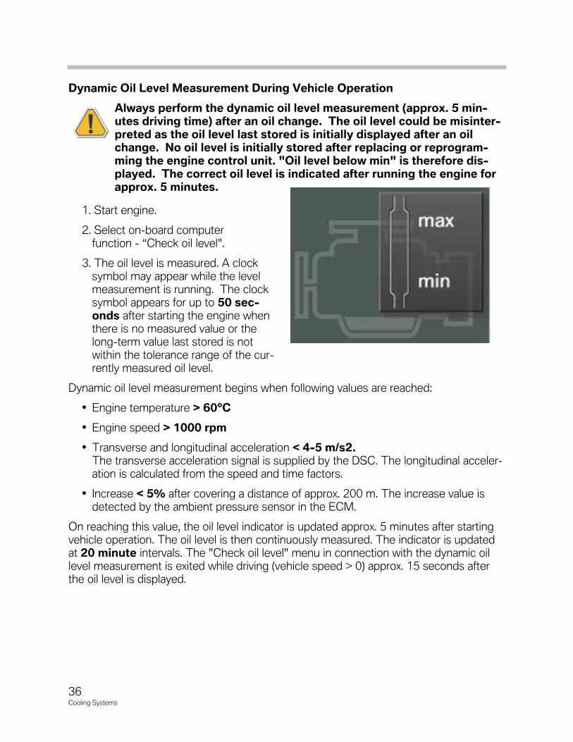
Dynamic Oil Level Measurement During Vehicle Operation
Always perform the dynamic oil level measurement (approx. 5 min-utes driving time) after an oil change. The oil level could be misinter-preted as the oil level last stored is initially displayed after an oilchange. No oil level is initially stored after replacing or reprogram-ming the engine control unit. "Oil level below min" is therefore dis-played. The correct oil level is indicated after running the engine forapprox. 5 minutes.
1. Start engine.
2. Select on-board computer function - “Check oil level".
3. The oil level is measured. A clock symbol may appear while the level measurement is running. The clocksymbol appears for up to 50 sec-onds after starting the engine whenthere is no measured value or thelong-term value last stored is notwithin the tolerance range of the cur-rently measured oil level.
Dynamic oil level measurement begins when following values are reached:
• Engine temperature > 60°C
• Engine speed > 1000 rpm
• Transverse and longitudinal acceleration < 4-5 m/s2.The transverse acceleration signal is supplied by the DSC. The longitudinal acceler-ation is calculated from the speed and time factors.
• Increase < 5% after covering a distance of approx. 200 m. The increase value isdetected by the ambient pressure sensor in the ECM.
On reaching this value, the oil level indicator is updated approx. 5 minutes after startingvehicle operation. The oil level is then continuously measured. The indicator is updatedat 20 minute intervals. The "Check oil level" menu in connection with the dynamic oillevel measurement is exited while driving (vehicle speed > 0) approx. 15 seconds afterthe oil level is displayed.
36Cooling�Systems
37Cooling�Systems
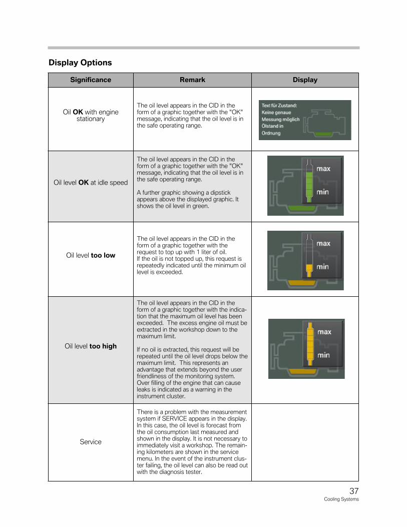
Display Options
Significance Remark Display
Oil OK with enginestationary
The oil level appears in the CID in theform of a graphic together with the "OK" message, indicating that the oil level is inthe safe operating range.
Oil level OK at idle speed
The oil level appears in the CID in theform of a graphic together with the "OK" message, indicating that the oil level is inthe safe operating range.
A further graphic showing a dipstickappears above the displayed graphic. Itshows the oil level in green.
Oil level too low
The oil level appears in the CID in theform of a graphic together with therequest to top up with 1 liter of oil. If the oil is not topped up, this request isrepeatedly indicated until the minimum oillevel is exceeded.
Oil level too high
The oil level appears in the CID in theform of a graphic together with the indica-tion that the maximum oil level has beenexceeded. The excess engine oil must beextracted in the workshop down to themaximum limit.
If no oil is extracted, this request will berepeated until the oil level drops below themaximum limit. This represents an advantage that extends beyond the userfriendliness of the monitoring system.Over filling of the engine that can causeleaks is indicated as a warning in theinstrument cluster.
Service
There is a problem with the measurementsystem if SERVICE appears in the display.In this case, the oil level is forecast fromthe oil consumption last measured andshown in the display. It is not necessary toimmediately visit a workshop. The remain-ing kilometers are shown in the servicemenu. In the event of the instrument clus-ter failing, the oil level can also be read outwith the diagnosis tester.

NOTESPAGE
38Cooling�Systems
The engine control unit of the N54 engine controls the coolant pump according torequirements:
• Low output in connection with low cooling requirements and low outside temperatures
• High output in connection with high cooling requirements and high outside temperatures
The coolant pump may also be completely switched off under certain circumstances,e.g. to allow the coolant to heat up rapidly during the warm-up phase. However, thisonly occurs when no heating is required and the outside temperature is within the per-mitted range.
The coolant pump also operates differently than conventional pumps when controllingthe engine temperature. To date, only the currently applied temperature could be controlled by the thermostat.
The software in the engine control unit now features a calculation model that can takeinto account the development of the cylinder head temperature based on load. In addition to the characteristic map control of the thermostat, the heat management system makes it possible to use various maps for the purpose of controlling the coolantpump. For instance, the engine control unit can adapt the engine temperature to matchthe current operating situation.
This means that four different temperature ranges can be implemented:
• 108°C ECO mode
• 104°C Normal mode
• 95°C High mode
• 90°C High + map-thermostat mode
The control system aims to set a higher cylinder-head temperature (108°C) if theengine control unit determines ECO (economy) mode based on the engine perfor-mance.
The engine is operated with relatively low fuel consumption in this temperature range asthe internal friction is reduced.
39Cooling Systems
Heat Management
An increase in temperature therefore favors slower fuel consumption in the low loadrange. In HIGH and map-thermostat mode, the driver wishes to utilize the optimumpower development of the engine. The cylinder-head temperature is reduced to 90°Cfor this purpose. This results in improved volumetric efficiency, thus increasing theengine torque. The engine control unit can now set a certain temperature mode adaptedto the respective operating situation. Consequently, it is possible to influence fuel consumption and power output by means of the cooling system.
The temperatures specified only ever represent a target value, the attainment of which isdependent on many factors. These temperatures are first and foremost not attained precisely.
The consumption-reducing and power increasing effects arise in each case in a temperature spectrum. The function of the cooling system is to provide the optimal cooling output according to the boundary conditions under which the engine is beingoperated.
40Cooling Systems

41Cooling Systems
Intelligent Heat Management Options
The previous section dealt with the various temperature ranges in which heat management is effected. However, an electrically driven coolant pump makes availableeven further options. For instance, it is now possible to warm up the engine without recirculating the coolant or to allow the pump to continue to operate after turning off theengine to facilitate heat dissipation. The advantages offered by this type of pump are listed in the following table:
Consumption
• Faster warm-up as coolant is not recirculateduntil needed
• Increased compression ratio due to greatercooling output all full load as compared to simi-lar engines without this option
Emissions
• Faster engine warm-up by drastically reducedpump speed and the lower volumetric flow ofcoolant
• Reduced friction
• Reduced fuel consumption
• Reduced exhaust emissions
Power Output
• Component cooling independent of enginespeed
• Requirement controlled coolant pump output
• Avoidance of power loss
Comfort
• Optimum volumetric flow
- Heating capacity reduced as required
- Residual heat with engine stationary
Component Protection
• After-running of electric coolant pump =improved heat dissipation from engine switchoff point. Allows protection of turbochargersby reduced oil “coking” during heat soak.
42Cooling Systems
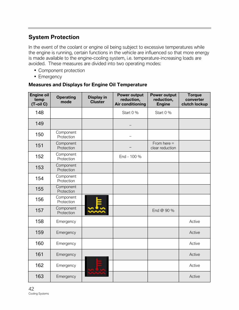
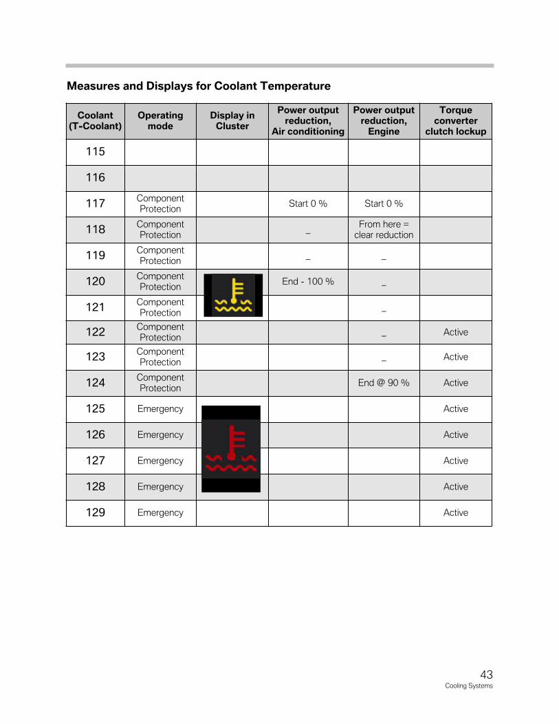
System Protection
In the event of the coolant or engine oil being subject to excessive temperatures whilethe engine is running, certain functions in the vehicle are influenced so that more energyis made available to the engine-cooling system, i.e. temperature-increasing loads are avoided. These measures are divided into two operating modes:
• Component protection
• Emergency
Measures and Displays for Engine Oil Temperature
Engine oiltemp
(T-oil C)
Operatingmode
Display inCluster
Power outputreduction,
Air conditioning
Power outputreduction,
Engine
Torque converter
clutch lockup
148 Start 0 % Start 0 %
149 _
150ComponentProtection
_
151ComponentProtection
_From here =
clear reduction
152ComponentProtection
End - 100 %
153ComponentProtection
154ComponentProtection
155ComponentProtection
156ComponentProtection
157ComponentProtection
End @ 90 %
158 Emergency Active
159 Emergency Active
160 Emergency Active
161 Emergency Active
162 Emergency Active
163 Emergency Active
43Cooling Systems
Measures and Displays for Coolant Temperature
Coolant (T-Coolant)
Operatingmode
Display inCluster
Power outputreduction,
Air conditioning
Power outputreduction,
Engine
Torque converter
clutch lockup
115
116
117ComponentProtection
Start 0 % Start 0 %
118ComponentProtection
_From here =
clear reduction
119ComponentProtection
_ _
120ComponentProtection
End - 100 % _
121ComponentProtection
_
122ComponentProtection
_ Active
123ComponentProtection
_ Active
124ComponentProtection
End @ 90 % Active
125 Emergency Active
126 Emergency Active
127 Emergency Active
128 Emergency Active
129 Emergency Active

44Cooling Systems
NOTESPAGE