Embed Size (px)
Citation preview
Initial Print Date: 03/05
Table of Contents
Subject Page
Basic Engine Measurements . . . . . . . . . . . . . . . . . . . . . . . . . . . . . . . . . . .3Vernier Measurement . . . . . . . . . . . . . . . . . . . . . . . . . . . . . . . . . . . . . . . . . . .4MIcrometer Measurements . . . . . . . . . . . . . . . . . . . . . . . . . . . . . . . . . . . . . .6
Metric Micrometer Construction . . . . . . . . . . . . . . . . . . . . . . . . . . . . . . .6Dial Indicator Measurements . . . . . . . . . . . . . . . . . . . . . . . . . . . . . . . . . . . .10
Examples of Dial Indicator Measurements . . . . . . . . . . . . . . . . . . . . .11
Additional Engine Measurements . . . . . . . . . . . . . . . . . . . . . . . . . . . . .14Cylinder Head Measurement . . . . . . . . . . . . . . . . . . . . . . . . . . . . . . . . . . .14Piston Measurements . . . . . . . . . . . . . . . . . . . . . . . . . . . . . . . . . . . . . . . . . .16Piston Ring Measurements . . . . . . . . . . . . . . . . . . . . . . . . . . . . . . . . . . . . .17Cylinder Bore . . . . . . . . . . . . . . . . . . . . . . . . . . . . . . . . . . . . . . . . . . . . . . . . .18
Metric System . . . . . . . . . . . . . . . . . . . . . . . . . . . . . . . . . . . . . . . . . . . . . . .20Metric System Denominations . . . . . . . . . . . . . . . . . . . . . . . . . . . . . . . . . .20Metric Reference Chart . . . . . . . . . . . . . . . . . . . . . . . . . . . . . . . . . . . . . . . .21Metric System Conversion Charts . . . . . . . . . . . . . . . . . . . . . . . . . . . . . . .22Pressure Conversion Chart . . . . . . . . . . . . . . . . . . . . . . . . . . . . . . . . . . . . .23
Basic Measuring Techniques
Revision Date:
2Basic Measuring Techniques
Basic Measuring Techniques
Model: All
After completion of this module you will be able to:
• Use basic measuring tools
• Perform basic engine measurements
• Understand metric measurements
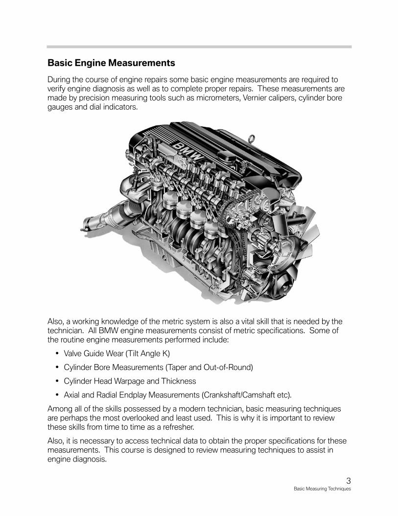
Basic Engine Measurements
During the course of engine repairs some basic engine measurements are required toverify engine diagnosis as well as to complete proper repairs. These measurements aremade by precision measuring tools such as micrometers, Vernier calipers, cylinder boregauges and dial indicators.
Also, a working knowledge of the metric system is also a vital skill that is needed by thetechnician. All BMW engine measurements consist of metric specifications. Some ofthe routine engine measurements performed include:
• Valve Guide Wear (Tilt Angle K)
• Cylinder Bore Measurements (Taper and Out-of-Round)
• Cylinder Head Warpage and Thickness
• Axial and Radial Endplay Measurements (Crankshaft/Camshaft etc).
Among all of the skills possessed by a modern technician, basic measuring techniquesare perhaps the most overlooked and least used. This is why it is important to reviewthese skills from time to time as a refresher.
Also, it is necessary to access technical data to obtain the proper specifications for thesemeasurements. This course is designed to review measuring techniques to assist inengine diagnosis.
3Basic Measuring Techniques

Vernier Measurement
The Vernier scale is used on various measuring tools such as the Vernier caliper and theDepth Gauge. The Vernier scale can be used with Fractional (US) and Metric systems.For the purposes of this training module we will always refer to the Metric Vernier scale.
The Vernier scale consists of a fixed scale and a sliding scale. The fixed scale is dividedwith graduations in 1 millimeter increments. The sliding scale has 10 graduations inincrements of .5.
In order to read a measurement, use the zero mark on the left end of the vernier scale touse as a guide to read a measurement on the fixed scale.
In the example shown at the right, the zeromark is resting between 26 and 27 mm.Therefore the base measurement is 26 mm.
Next, the decimal measurement must betaken. For this, find a line on the Vernier thatmost closely matches any line on the fixedscale.
Using the example drawing, the “4” on theVernier scale is lining up directly with a line onthe fixed scale.
Combining the previous reading with this read-ing, the result would be 26.4 mm.
The designations on the Vernier scale are in increments of .5. For example, if a reading onthe Vernier scale falls on the .5 (i.e. 2.5, 3.5 etc) designation this would indicate 5/100th’sof a millimeter.
4Basic Measuring Techniques
1 2 3 4 5 6 7 8 9 10 11 12 13 14 15 16 17 18 19 2 0 21 2 2 2 3 2 4 2 5 2 6 27 2 8 2 9 3 0 31 32
0 1 2 3 4 5 6 7 8 9 10
Vernier Scale (sliding scale)
Fixed Scale (in 1 mm increments)
Depth Gauge with Vernier Scale
2 3 4 5 6 7
0 1 2 3 4 5 6 7 8 9 10

Classroom Exercise - Vernier Readings
Fill in the correct Vernier scale readings in the spaces provided below.
5Basic Measuring Techniques
5 6 7 8 9 10
0 1 2 3 4 5 6 7 8 9 10
27 2 8 2 9 3 0
0 1 2 3 4 5 6 7 8 9 10
14 15 16 17 18 19
0 1 2 3 4 5 6 7 8 9 10
1 2 3 4 5 6
0 1 2 3 4 5 6 7 8 9 10
Vernier 1
Vernier 3 Vernier 4
Vernier 2
Vernier Reading 1:
___________________________________
Vernier Reading 4:
___________________________________
Vernier Reading 2:
___________________________________
Vernier Reading 3:
___________________________________
MIcrometer Measurements
Another valuable measuring tool is the micrometer, which can be used for measurementssuch as bearing journal diameter, cylinder head thickness, valve shim thickness and brakerotor thickness etc. Micrometers also come in configurations for inside measurements aswell.
The micrometer scale comes in both fractional and metric varieties. We will cover onlythe metric micrometer scale in this course.
First you must familiarize yourself with the construction of the micrometer in order tounderstand how measurements are made.
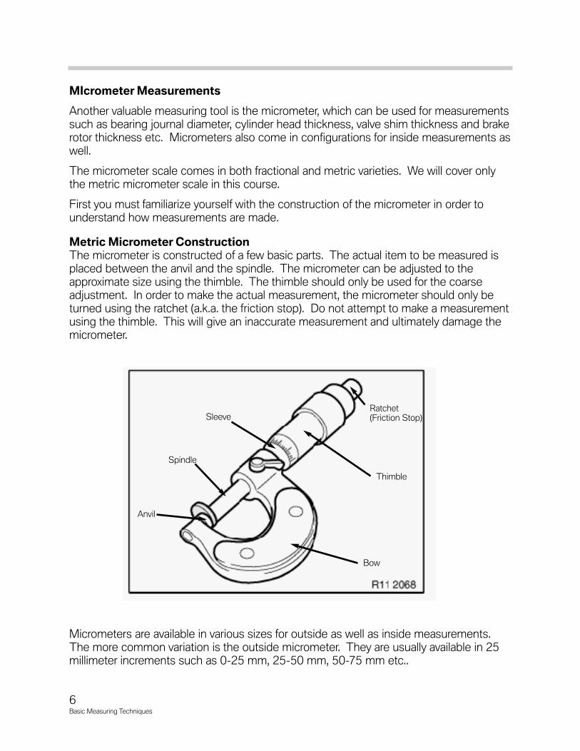
Metric Micrometer ConstructionThe micrometer is constructed of a few basic parts. The actual item to be measured isplaced between the anvil and the spindle. The micrometer can be adjusted to theapproximate size using the thimble. The thimble should only be used for the coarseadjustment. In order to make the actual measurement, the micrometer should only beturned using the ratchet (a.k.a. the friction stop). Do not attempt to make a measurementusing the thimble. This will give an inaccurate measurement and ultimately damage themicrometer.
Micrometers are available in various sizes for outside as well as inside measurements.The more common variation is the outside micrometer. They are usually available in 25millimeter increments such as 0-25 mm, 25-50 mm, 50-75 mm etc..
6Basic Measuring Techniques
Anvil
Bow
Spindle
Sleeve
Thimble
Ratchet(Friction Stop)
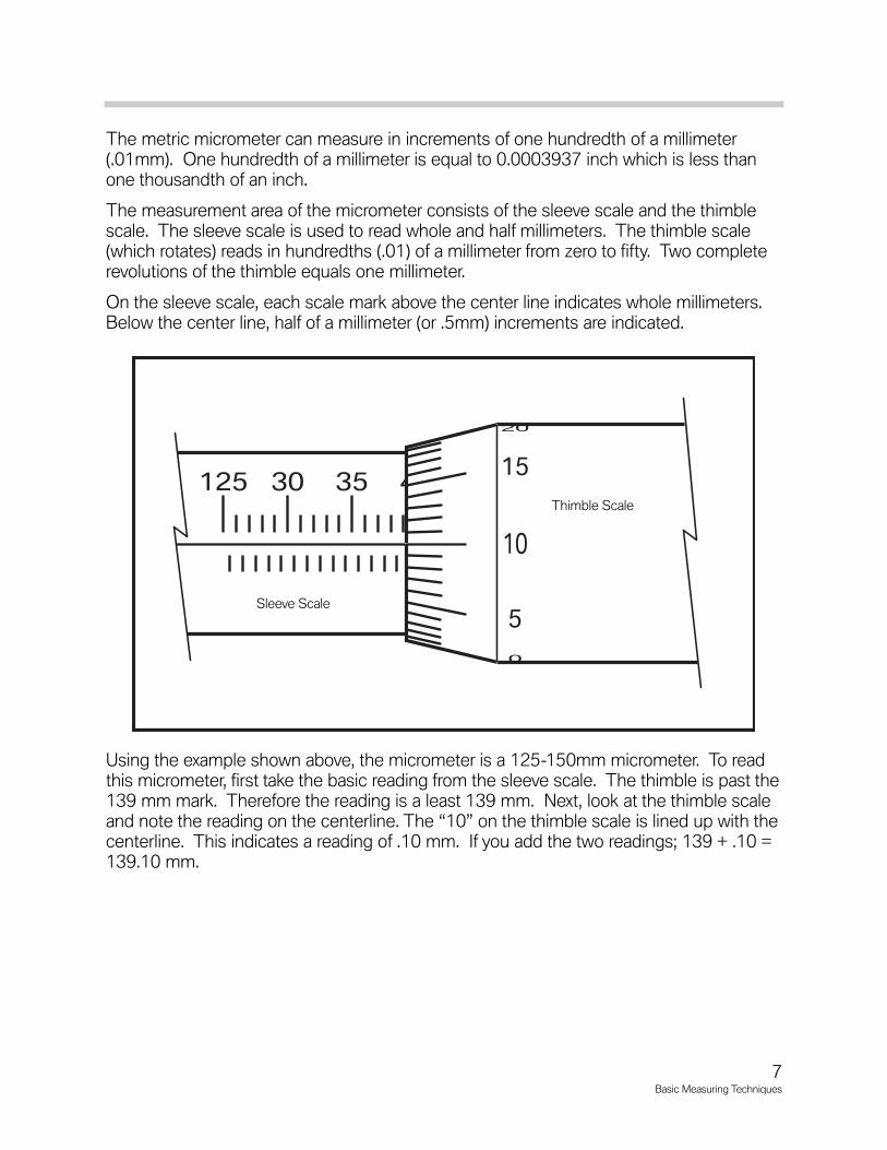
The metric micrometer can measure in increments of one hundredth of a millimeter(.01mm). One hundredth of a millimeter is equal to 0.0003937 inch which is less thanone thousandth of an inch.
The measurement area of the micrometer consists of the sleeve scale and the thimblescale. The sleeve scale is used to read whole and half millimeters. The thimble scale(which rotates) reads in hundredths (.01) of a millimeter from zero to fifty. Two completerevolutions of the thimble equals one millimeter.
On the sleeve scale, each scale mark above the center line indicates whole millimeters.Below the center line, half of a millimeter (or .5mm) increments are indicated.
Using the example shown above, the micrometer is a 125-150mm micrometer. To readthis micrometer, first take the basic reading from the sleeve scale. The thimble is past the139 mm mark. Therefore the reading is a least 139 mm. Next, look at the thimble scaleand note the reading on the centerline. The “10” on the thimble scale is lined up with thecenterline. This indicates a reading of .10 mm. If you add the two readings; 139 + .10 =139.10 mm.
7Basic Measuring Techniques
125 30 35 40 45 150
10
15
20
0
5
Thimble Scale
Sleeve Scale

Classroom Exercises - Micrometer Measurements
Fill in the correct micrometer readings in the spaces provided below.
8Basic Measuring Techniques
0 5 10 15 20 25
25
30
35
20
125 30 35 40 45 150
30
35
40
20
25
25 30 35 40 45 50
30
35
40
25
50 55 60 65 70 75
45
0
5
40
Micrometer Reading 1:
___________________________________
Micrometer Reading 4:
___________________________________
Micrometer Reading 3:
___________________________________
Micrometer Reading 2:
___________________________________
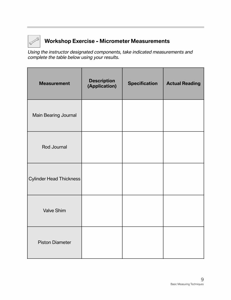
Workshop Exercise - Micrometer Measurements
Using the instructor designated components, take indicated measurements andcomplete the table below using your results.
9Basic Measuring Techniques
Measurement Description(Application) Specification Actual Reading
Main Bearing Journal
Rod Journal
Cylinder Head Thickness
Valve Shim
Piston Diameter
Dial Indicator Measurements
The dial indicator is used to measure the travel or movement of a specific item. It canalso be used to measure axial and radial runout. In engine measurement applications, thedial indicator can be used to measure valve guide wear, axial movement of the crankshaft(thrust), and runout of flywheels and harmonic balancers.
First, it is important to familiarize yourself with Dial Indicator construction. The face of thedial indicator consists of a moveable bezel which is also attached to the large measuringscale. This allows the tool be be brought to the “zero point” when needed.
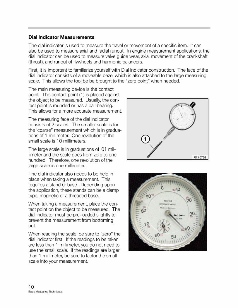
The main measuring device is the contactpoint. The contact point (1) is placed againstthe object to be measured. Usually, the con-tact point is rounded or has a ball bearing.This allows for a more accurate measurement.
The measuring face of the dial indicatorconsists of 2 scales. The smaller scale is forthe ‘coarse” measurement which is in gradua-tions of 1 millimeter. One revolution of thesmall scale is 10 millimeters.
The large scale is in graduations of .01 mil-limeter and the scale goes from zero to onehundred. Therefore, one revolution of thelarge scale is one millimeter.
The dial indicator also needs to be held inplace when taking a measurement. Thisrequires a stand or base. Depending uponthe application, these stands can be a clamptype, magnetic or a threaded base.
When taking a measurement, place the con-tact point on the object to be measured. Thedial indicator must be pre-loaded slightly toprevent the measurement from bottomingout.
When reading the scale, be sure to “zero” thedial indicator first. If the readings to be takenare less than 1 millimeter, you do not need touse the small scale. If the readings are largerthan 1 millimeter, be sure to factor the smallscale into your measurement.
10Basic Measuring Techniques
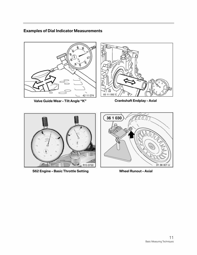
Examples of Dial Indicator Measurements
11Basic Measuring Techniques
Valve Guide Wear - Tilt Angle “K”
S62 Engine - Basic Throttle Setting Wheel Runout - Axial
Crankshaft Endplay - Axial
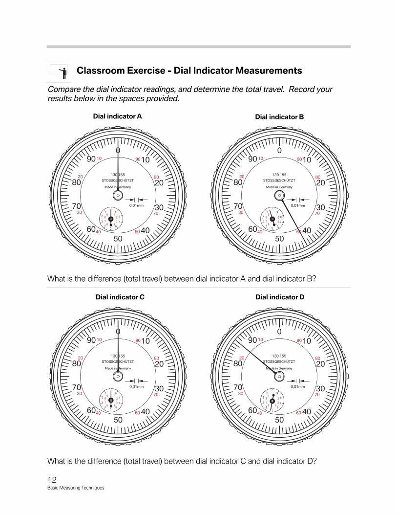
Classroom Exercise - Dial Indicator Measurements
Compare the dial indicator readings, and determine the total travel. Record yourresults below in the spaces provided.
What is the difference (total travel) between dial indicator A and dial indicator B?
What is the difference (total travel) between dial indicator C and dial indicator D?
12Basic Measuring Techniques
010
20
30
40 60
70
80
9090
80
70
6050
40
30
20
0,01mm
11
23
4678
92
34
56
7
8
9
130 155STOSSGESCHÜTZT
Made in Germany
100
10
20
30
40 60
70
80
9090
80
70
6050
40
30
20
0,01mm
11
23
4678
92
34
56
7
8
9
130 155STOSSGESCHÜTZT
Made in Germany
10
010
20
30
40 60
70
80
9090
80
70
6050
40
30
20
0,01mm
11
23
4678
92
34
56
7
8
9
130 155STOSSGESCHÜTZT
Made in Germany
100
10
20
30
40 60
70
80
9090
80
70
6050
40
30
20
0,01mm
11
23
4678
92
34
56
7
8
9
130 155STOSSGESCHÜTZT
Made in Germany
10
Dial indicator A Dial indicator B
Dial indicator C Dial indicator D

Workshop Exercise - Dial Indicator Measurements
Using the instructor designated dial indicator, measure the indicated componentsand complete the table below using your results.
13Basic Measuring Techniques
Measurement Description Specification Actual Reading
Tilt Angle “K”
Crankshaft Endplay
Other
Other
Additional Engine Measurements
During engine repair procedures it is sometimes necessary to assess engine wear tomake determinations on parts replacement. Also, some engine measurements are need-ed to verify a previous diagnosis.
For example, a cylinder leakdown test could indicate a cylinder sealing concern. Oncethe engine is disassembled, it would be necessary to verify this condition by checking thepiston and piston ring condition. If OK, the next step would be to determine the conditionof the cylinder bore. At this point, the cylinders should be checked for taper (conicity) andfor out-of-round. The correct measurements could mean the difference between justreplacing the rings and/or pistons or replacing the engine block. This is why it is neces-sary to make accurate measurements when needed.
Some of the other routine engine measurements include:
• Cylinder head warpage
• Cylinder head thickness (on some applications)
• Piston rings - end gap and axial clearance
* Cylinder bore - including out-of-round and taper
Cylinder Head Measurement
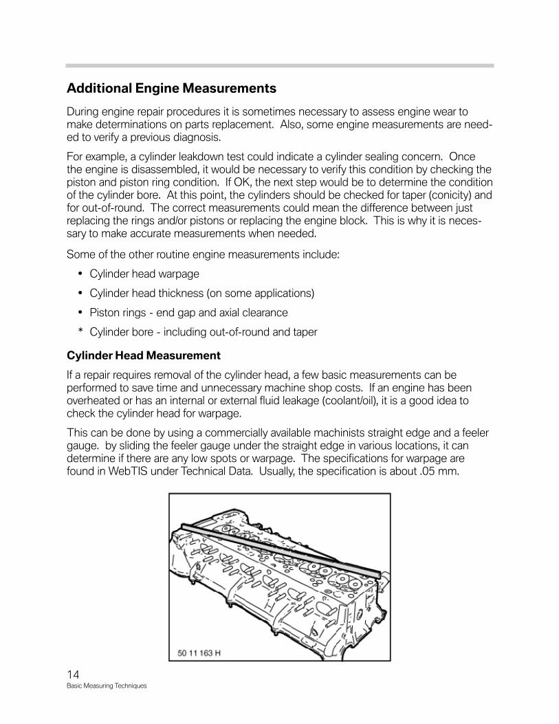
If a repair requires removal of the cylinder head, a few basic measurements can be performed to save time and unnecessary machine shop costs. If an engine has beenoverheated or has an internal or external fluid leakage (coolant/oil), it is a good idea tocheck the cylinder head for warpage.
This can be done by using a commercially available machinists straight edge and a feelergauge. by sliding the feeler gauge under the straight edge in various locations, it candetermine if there are any low spots or warpage. The specifications for warpage arefound in WebTIS under Technical Data. Usually, the specification is about .05 mm.
14Basic Measuring Techniques
Also, check to see if the cylinder head has a specification for machining limit. If so, it maybe possible to have the cylinder head re-surfaced. Depending on the amount of materialremoved during the machining process, it may be necessary to install a thicker head gasket. There are some “service” head gaskets available through the part s department.
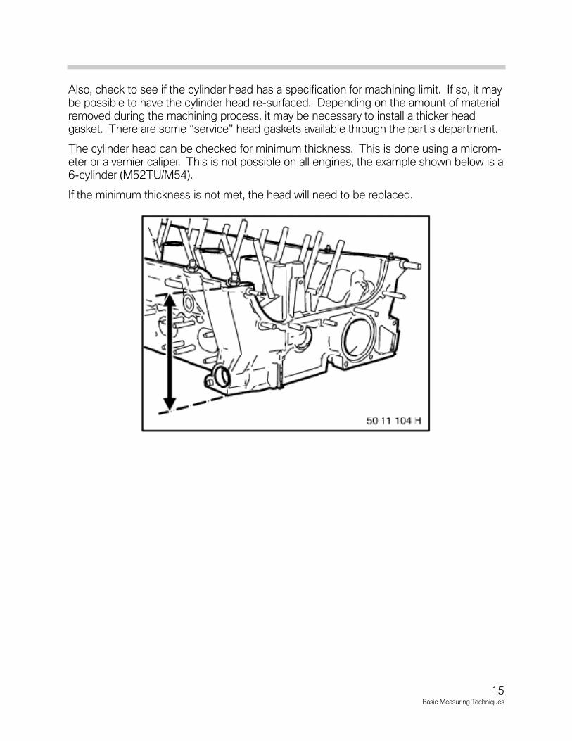
The cylinder head can be checked for minimum thickness. This is done using a microm-eter or a vernier caliper. This is not possible on all engines, the example shown below is a6-cylinder (M52TU/M54).
If the minimum thickness is not met, the head will need to be replaced.
15Basic Measuring Techniques

Piston Measurements
When replacing pistons and/or piston rings, there are some basic measurements thatneed to be made. When fitting a piston to a cylinder bore, the piston diameter should bechecked to ensure a proper fit.
The piston diameter is measured using a micrometer. The measurement is taken at aspecified point (A) which is 90 degrees from the piston pin axis. Each engine has a spe-cific location to measure piston diameter. For example, the illustration below shows mea-suring Point A. The specification for this engine (N62) is 18 mm. So the piston diameteris measured 18 mm from the bottom of the piston skirt.
The piston diameter, when subtracted from the cylinder bore equals the cylinder wall topiston clearance. If the clearance measurement obtained is not correct, re-check yourreadings.
16Basic Measuring Techniques
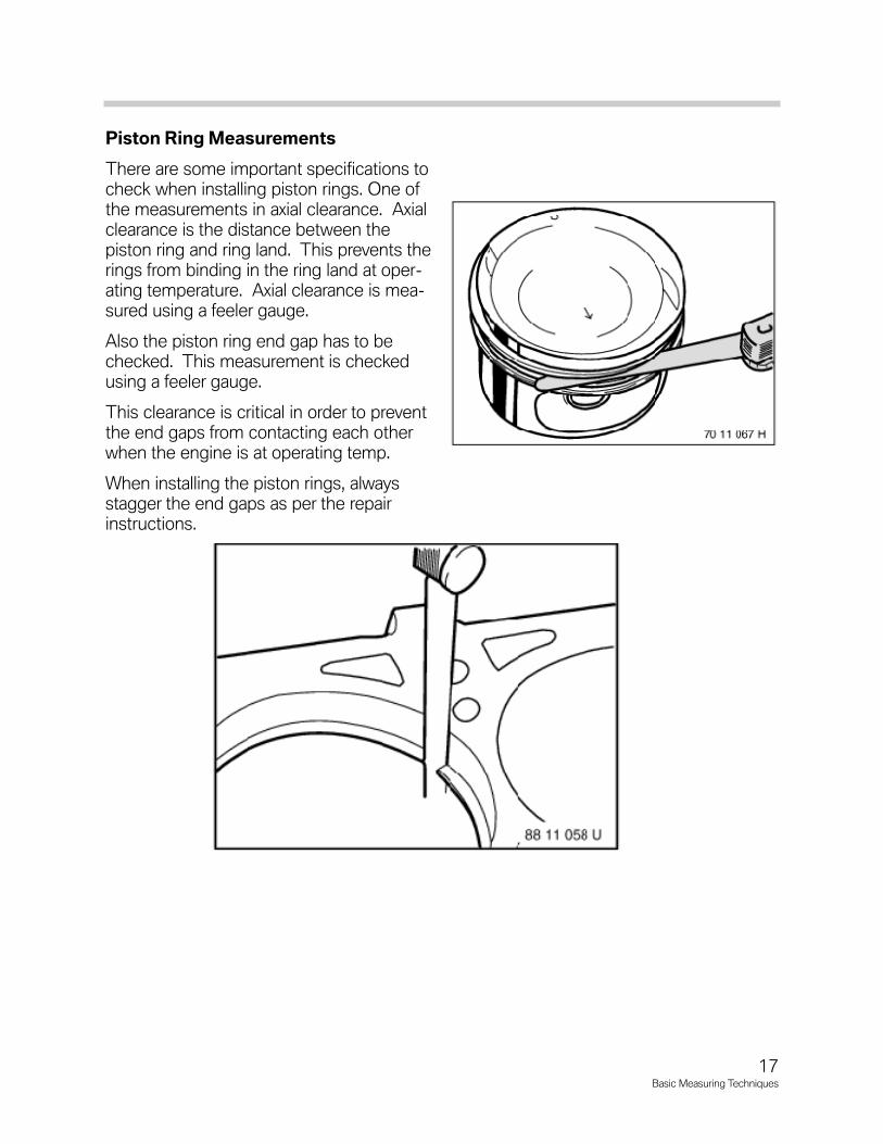
Piston Ring Measurements
There are some important specifications tocheck when installing piston rings. One ofthe measurements in axial clearance. Axialclearance is the distance between the piston ring and ring land. This prevents therings from binding in the ring land at oper-ating temperature. Axial clearance is mea-sured using a feeler gauge.
Also the piston ring end gap has to bechecked. This measurement is checkedusing a feeler gauge.
This clearance is critical in order to preventthe end gaps from contacting each otherwhen the engine is at operating temp.
When installing the piston rings, alwaysstagger the end gaps as per the repairinstructions.
17Basic Measuring Techniques
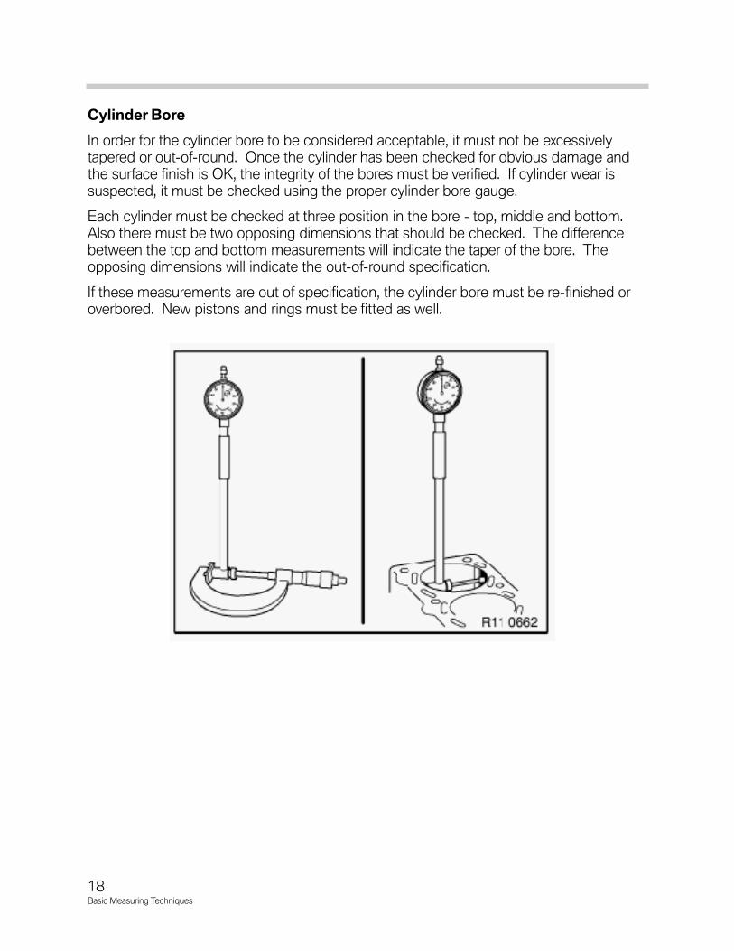
Cylinder Bore
In order for the cylinder bore to be considered acceptable, it must not be excessivelytapered or out-of-round. Once the cylinder has been checked for obvious damage andthe surface finish is OK, the integrity of the bores must be verified. If cylinder wear is suspected, it must be checked using the proper cylinder bore gauge.
Each cylinder must be checked at three position in the bore - top, middle and bottom.Also there must be two opposing dimensions that should be checked. The differencebetween the top and bottom measurements will indicate the taper of the bore. Theopposing dimensions will indicate the out-of-round specification.
If these measurements are out of specification, the cylinder bore must be re-finished oroverbored. New pistons and rings must be fitted as well.
18Basic Measuring Techniques

Workshop Exercise - Cylinder Bore Measurements
Using an instructor designated engine block, measure the indicated cylinder bore andcomplete the table below. Calculate the taper and out-of-round measurements.
19Basic Measuring Techniques
Measurement A Measurement B Out-of-Round
Cylinder Top
Cylinder Middle
Cylinder Bottom
Cylinder Taper
Metric System
All BMW specifications are metric. Therefore, a thorough knowledge of those areas onthe metric system which apply to BMW vehicles is vital to a BMW Service Technician.
The unit of length, and the basis for all other metric units of measurement is the meter.The meter (1 meter), as a point of reference, is slightly longer that a yard (39.37 inches).
The divisions of a meter are hundredths and thousandths. One hundredth of a meter iscalled a centimeter, and is equal to .3937 inch or about half the diameter of a nickel.
One thousandth of a meter is called a millimeter. The small marks between the centime-ter increments are each one millimeter, or one tenth of a centimeter. And as a point ofreference, a standard paper clip is about one millimeter thick.
Metric System Denominations
Throughout the metric system, common to all units of measurement, are prefixes whichdesignate multiples or fractions of the unit.
For automotive applications, the most common prefixes are centi; designating one-hun-dredth; milli; for one thousandth and kilo- for one thousand.
There are letters uniformly used throughout the system to label the divisions or multiplesof each unit of measurement. The letter “m” represents milli, “c’ is for centi and “k” is forkilo. These are then combined with the letter representing the unit of measurement.
For example, mm is millimeter, cm is centimeter and km is kilometer. The same appliesto liter which is the unit of volume and gram which is the unit of weight.
One kilogram is equal to one thousand grams which is equal to 2.2 pounds.
All metric measurements are directly related. For example, one thousand cubic centime-ters, or 10cm x 10cm x 10cm of water weighs one kilogram. The volume of those onethousand cc’s is one liter.
20Basic Measuring Techniques
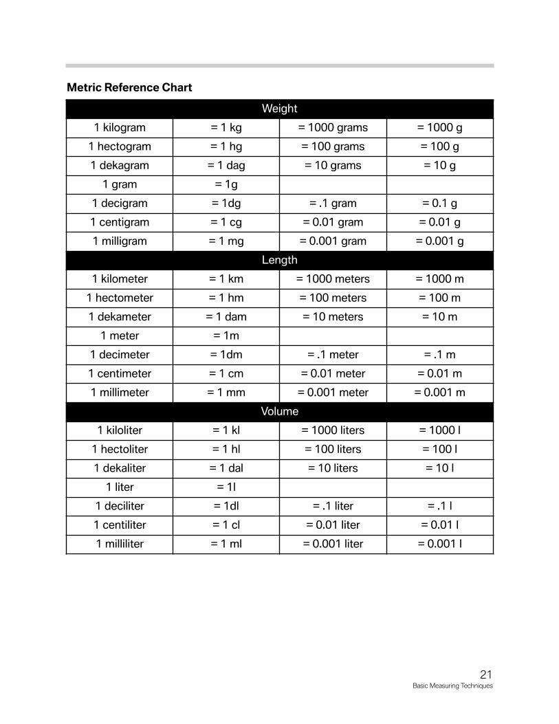
Metric Reference Chart
21Basic Measuring Techniques
Weight
1 kilogram = 1 kg = 1000 grams = 1000 g
1 hectogram = 1 hg = 100 grams = 100 g
1 dekagram = 1 dag = 10 grams = 10 g
1 gram = 1g
1 decigram = 1dg = .1 gram = 0.1 g
1 centigram = 1 cg = 0.01 gram = 0.01 g
1 milligram = 1 mg = 0.001 gram = 0.001 g
Length
1 kilometer = 1 km = 1000 meters = 1000 m
1 hectometer = 1 hm = 100 meters = 100 m
1 dekameter = 1 dam = 10 meters = 10 m
1 meter = 1m
1 decimeter = 1dm = .1 meter = .1 m
1 centimeter = 1 cm = 0.01 meter = 0.01 m
1 millimeter = 1 mm = 0.001 meter = 0.001 m
Volume
1 kiloliter = 1 kl = 1000 liters = 1000 l
1 hectoliter = 1 hl = 100 liters = 100 l
1 dekaliter = 1 dal = 10 liters = 10 l
1 liter = 1l
1 deciliter = 1dl = .1 liter = .1 l
1 centiliter = 1 cl = 0.01 liter = 0.01 l
1 milliliter = 1 ml = 0.001 liter = 0.001 l

Metric System Conversion Charts
22Basic Measuring Techniques
Linear Measure to Metric Linear Measure (Metric) to English
1 inch = 2.54 cm 1 mm = 0.03937 inch
12 inches = 1 foot = 30.48 cm 1 cm = 0.39 inch
3 feet = 1 yard = 0.91 m 1 m = 39.37 inch
5.5 yards = 1 rod = 5.03 m 1 km = 0.62 miles
5280 feet = 1 mile = 1.61 km
Square Measure to Metric Square Measure (Metric) to English
1 in2 = 6.45 cm2 1 mm2 = 0.002 in2
144 in2 = 1 ft 2 = 0.09 m2 1 cm2 = 0.16 in2
9 ft2 = 1 yd2 = 0.84 m2 1 m2 = 1549 in2
640 acres = 1mi2 = 2.59 km2 1 km2 = 0.39 mi2 = 247.10 acres
Cubic Measure to Metric Cubic Measure (Metric) to English
1 in3 = 16.39 cm3 1 mm3 = 0.000061 in3
1728 in3 = 1 yd3 = 0.76 m3 1 cm3 = 0.061 in3
27ft3 = 1 yd3 = 0.76 m3 1 m3 = 35.32 ft3
1 km3 = 0.24 mi3
Liquid Measure to Metric Liquid Measure (Metric) to English
1.81 in3 = 1 fluid oz. = 30 ml 1 ml = 0.03 fluid oz = 0.061 in3
1 pint = 0.47 l 1000 cm3 = 1 l = 61.02 in3 = 1.06 qt
57.75 in3 = 1 quart = 0.95 l 1 ft3 water = 62.5 lb
231 in3 = 1 gal = 3.79 l = 0.0038 m3
1 ft3 = 7.48 gal = 28.35 l
Weights to Metric Weight (Metric) to English
1 0z = 28.35 g 1 g = 0.035 oz
1 lb = 453.59 g 1 kg = 2.20 lb
1 lb = 0.45 kg 1 metric ton = 1000 kg = 1.102 tons = 2205 lb
1 ton = .91 metric ton
Temperature to Metric Temperature to Fahrenheit
F = 9/5C +32 C = 5/9 (F-32)
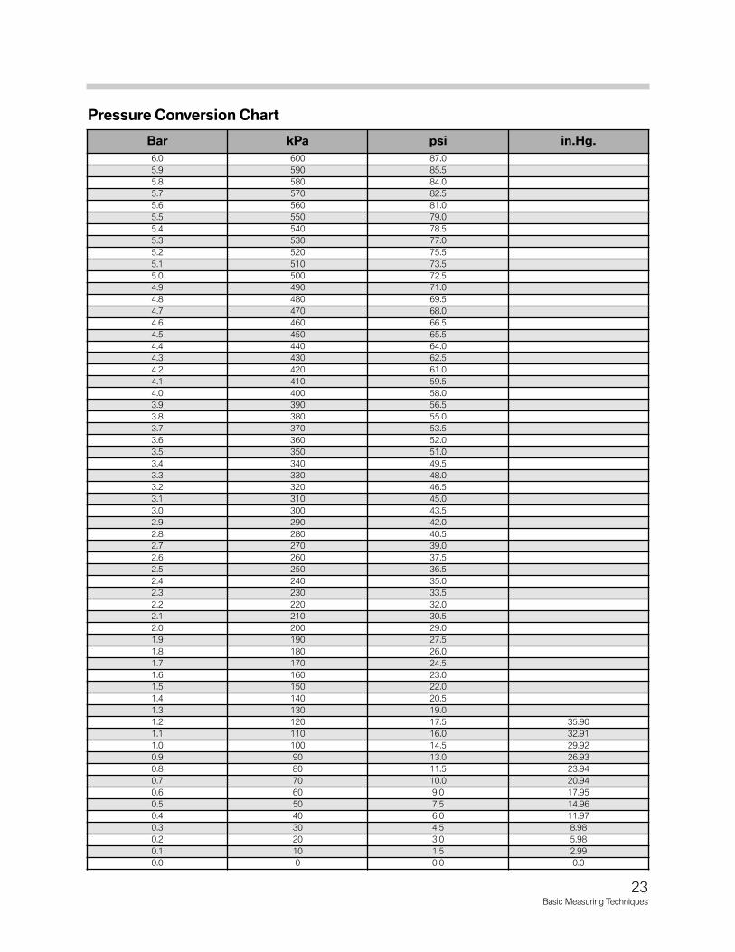
Pressure Conversion Chart
23Basic Measuring Techniques
Bar kPa psi in.Hg.6.0 600 87.05.9 590 85.55.8 580 84.05.7 570 82.55.6 560 81.05.5 550 79.05.4 540 78.55.3 530 77.05.2 520 75.55.1 510 73.55.0 500 72.54.9 490 71.04.8 480 69.54.7 470 68.04.6 460 66.54.5 450 65.54.4 440 64.04.3 430 62.54.2 420 61.04.1 410 59.54.0 400 58.03.9 390 56.53.8 380 55.03.7 370 53.53.6 360 52.03.5 350 51.03.4 340 49.53.3 330 48.03.2 320 46.53.1 310 45.03.0 300 43.52.9 290 42.02.8 280 40.52.7 270 39.02.6 260 37.52.5 250 36.52.4 240 35.02.3 230 33.52.2 220 32.02.1 210 30.52.0 200 29.01.9 190 27.51.8 180 26.01.7 170 24.51.6 160 23.01.5 150 22.01.4 140 20.51.3 130 19.01.2 120 17.5 35.901.1 110 16.0 32.911.0 100 14.5 29.920.9 90 13.0 26.930.8 80 11.5 23.940.7 70 10.0 20.940.6 60 9.0 17.950.5 50 7.5 14.960.4 40 6.0 11.970.3 30 4.5 8.980.2 20 3.0 5.980.1 10 1.5 2.990.0 0 0.0 0.0
Classroom Exercise - Review Questions
1. When using a micrometer, why is it important to only turn the thimble using the ratchet (friction stop) when making a measurement?
2. What are the increments on the thimble scale of a micrometer?
3. How should the diameter of a piston be measured?
4. One rotation of the large scale on a metric dial indicator is equal to_______.
24Basic Measuring Techniques
Classroom Exercise - Review Questions
5. What are some of the measurement that a dial indicator can be used for?
6. What are some of the measurements that can be performed on a cylinder head?
7. Explain taper and out-of-round on a cylinder bore:
25Basic Measuring Techniques