Embed Size (px)
Citation preview

-1-
LDM valveswith electromechanic actuators
01 - 02.109 16. .GB
®

®
-2-
L - linear characteristicKv/Kv = 0.0183 + 0.9817 . (H/H )100 100
R - equal-percentage characteristic (4-percentage)Kv/Kv = 0.0183 . e100
(4 . H/H100)
P - parabolic characteristicKv/Kv = 0.0183 + 0.9817 . (H/H )100 100
2
S - LDM spline characteristic®
Kv/Kv = 0.0183 + 0.269 . (H/H ) - 0.380 . (H/H )100 100 100
2
+ 1.096 . (H/H ) - 0.194 . (H/H )100
3
100
4
- 0.265 . (H/H ) + 0.443 . (H/H )100
5
100
6
Kv/Kv100
H/H1000
LP
R
S
1
0.9
0.8
0.7
0.6
0.5
0.4
0.3
0.2
0.1
0.1 0.2 0.3 0.4 0.5 0.6 0.7 0.8 0.9 1
Kv coefficient calculation
Calculation itself is carried out with respect to conditions ofregulating circuit and operating medium according toequations mentioned below. Control valve must be designedto be able to regulate maximal flow quantity at given operatingconditions. At the same time it is necessary to check whetherminimal flow quantity can be even regulated or not.
Condition is the following ratio
Because of eventual minus tolerance 10% of Kv against100
Kvs and requirement for possible regulation within range ofmaximal flow (decrement and increase of flow), producerrecommends to select Kvs value higher than maximaloperating Kv value:
It is necessary to take into account to which extent Q involvemax
"precautionary additions" that could result in valve oversizing.
r > Kvs / Kvmin
Kvs = 1.1 1.3 Kv�
Relations of Kv calculation
Flow characteristic selection in regardof valve stroke
To make right selection of valve flow characteristic, it issuitable to carry out checking of what stroke values will bereached in different operation states. We recommend to carryout such checking at least for minimal, nominal and maximalflow rates. The principle for flow characteristic selection is toavoid, if possible, 5 10% of the beginning and end of the valve�stroke range.To calculate valve stroke at different operating conditions withdifferent types of flow characteristics is possible with theadvantage of using LDM´s calculation programme VALVES.The programme serves for complete design of valve from Kvcalculation to specification of a concrete valve with its actuator.
Above critical flow of vapours and gases
When pressure ratio is above critical (p / p < 0.54), speed of2 1
flow reaches acoustic velocity at the narrowest section. Thisevent can cause higher level of noisiness. Then it is convenientto use a throttling system ensuring low noisiness (multi-steppressure reduction, damping orifice plate at outlet).
Dimensions and units
Valve flow characteristics
Pressure drop Pressure dropp > p /22 1
�p < p /21
�p p /21
p p /22 1
=>
=<
Qn
5141�n 1.T�p.p2
� 2.Qn
5141.p1
�n 1.T�
Qm
100v2
�p� Qm
1002vp1
�Qm
1002v.xp1
�Qm
100v .x2
�p�
Kv =
Liquid
Gas
Superh. steam
Sat. steam
Q100
�1
�p�
Marking UnitFlow coefficient under condition of units of flowKv
Flow rate in operating conditions (T , p )1 1QFlow rate in normal conditions (0 C, 0.101 Mpa)oQn Nm .h3 -1
Flow rate in operating conditions (T , p )1 1Qm kg.h-1
Name of dimension
p1 MPa Upstream absolute pressurep2 MPa Downstream absolute pressurepS MPa Absolute pressure of saturated steam at given temperature (T )1
�p MPa Valve differential pressure ( p = p - p )� 1 2
�1 kg.m-3 Process medium density in operating conditions (T , p )1 1
�n kg.Nm-3 Gas density in normal conditions (0 C, 0.101 Mpa)v2 m .kg3 -1 Specific volume of steam when temperature T and pressure p1 2
v m .kg3 -1 Specific volume of steam when temperature T and pressure p /21 1
T1 K Absolute temperature at valve inlet (T = 273 + t )1 1
xr
11
Proportionate weight volume of saturated steam in wet steamRangeability
Flow coefficient at minimal flow rateKvmin
Valve nominal flow coefficientKvs
m .h3 -1
m .h3 -1
m .h3 -1
m .h3 -1
o
Flow coefficient at nominal strokeKv100 m .h3 -1

®
-3-
Packing - DRSpack (PTFE)®
DRSpack (Direct Radial Sealing Pack) is a packing with high®
tightness at both low and high operating pressure values.It is the most used type of packing suitable for temperaturesranging from 0 C to 260 C. The pH range is from 0 to 14. Theo o
packing enables using of actuators with low linear force. Thedesign enables an easy change of the whole packing. Theaverage service life of DRSpack is more than 500 000 cycles.®
Packing - O -ring EPDMPacking is designed for non-aggressive media with tempe-rature from 0 C to 140 C. Packing excels with its reliability ando o
long time tightness. It has ability of sealing even if the valvestem is a bit damaged. Low frictional forces enables valve to beactuated with a low-linear-force actuator. Service life of sealingrings depends on operating conditions and it is more than 400000 cycles on average. Packing - Bellows
Bellows packing is suitable for low and high temperaturesranging from -50 C to 550 C. Bellows ensures absolute tightnesso o
to environment. Packing is equipped with safety PTFE packingas standard to prevent medium from leaking in case of damageto bellows. Intensive linear forces are not required.
Principles for plug type selectionV-ported plugs should not to be used in above - critical differentialpressures with inlet pressure p 0,4 MPa and for regulation ofsaturated steam. In these cases we recommend to use a perfo-rated plug. The perforated plug should be also used alwayswhen cavitation may occur due to a high differential pressurevalue or valve ports erosion caused by high speed of processmedium flow. If the parabolic plug is used (because of smallKvs) for above-critical differential pressures, it is necessary toclose both plug and seat with a hard metal overlay, i.e. stellitedtrim.
1>=
Application of bellows packingBellows packing is suitable for applications with veryaggressive, toxic or other dangerous media that requireabsolute tightness to environment. In such case, it is necessaryto check compatibility of used body material as well as thevalve inner parts material with process medium. It isrecommended to use bellows with safety packing preventingmedium from leaking in case of damage to bellows when thereis an extremely dangerous process medium used.Bellows is also a great solution to use of process medium eitherwith temperature below zero when ice accretions causepremature damage to packing or with high temeperatureswhen bellows ensures medium cooling.
Applied to RV 102, RV 103 Applied to RV 2xx
Packing - GraphiteThis type of packing can be used for media with temperature upto 550 C and pH range: 0 to 14. Packing can be "sealed up"o
either by screwing the packing screw in or adding anothersealing ring. In regard of intensive frictional forces, graphitepacking is suitable for actuators with a sufficient linear force.
Bellows material200 Co
1.45411.4571
Temperature
100 00090 000
300 Co
40 00034 000
400 Co
28 00022 000
500 Co
7 00013 000
550 Co
not applicable8 000
Service life of bellows packing
Values specified in the table above show minimal guaranteednumber of cycles with the valve full stroke when the bellows isfully lenghtened and pressed. In regulation, when the valve
moves only in a portion of the stroke range at the inner centre ofthe valve, the service life of the bellows is many times longerthen depending on concrete operating conditions.
Rangeability2
Rangeability is the ratio of the biggest value of flow coefficientto the smallest value. In fact it is the ratio (under the sameconditions) of highest regulated flow rate value to its lowestvalue.The lowest or minimal regulated flow rate is alwayshigher than 0.

®
-4-
Determination of valve´s real authority
Value should be at least equal to 0,3. A chosen valveachecking is then satisfactory.Caution: the valve's authority calculation should be related toa valve pressure difference in its closed position i.e. dispositionpressure value in a branch p when flow rate is zero, not to� AVAIL.
a pressure value of a pump p , because, due to pipeline� PUMP
circuit pressure drops up to the spot where the regulatingbranch is connected, the following equation applies: p <� AVAIL.
�p . In such cases we consider for simplicity the following:PUMP
� � �p = p = p .AVAIL. H100 AVAIL. H0 DISP
Checking of rangeability
We carry out the same checking for minimal flow rate Q =1,3MIN
m .h . The following differential pressure values correspond to3 -1
the min. flow rate: p = 0,40 kPa, p = 0,66 kPa.� �APPLIANCE QMIN PIPELINE QMIN
�p = 80 - 0,4 - 0,66 = 78,94 = 79 kPa.VALVE QMIN
Necessary rangeability value
shall be lower than mentioned rangeability value of r = 50.Checking is then satisfactory.
Selection of suitable flow characteristic
On the basis of calculated values Kv and Kv , it is possible toNOM MIN
read the appropriate stroke values from the graph for individualtypes of flow characteristics of the valve and choose the mostsuitable one accordingly. Here we have h = 96%, h = 41% forNOM MIN
equal-percentage characteristic. In that case, LDMspline flow®
characteristic is more suitable (93% and 30% of the stroke). Itcorresponds to the following specification code :
RV 21x XXX 1423 S1 16/220-32
Procedure for designing of two-wayvalve
Given: medium water, 155 C, static pressure at piping spoto
1000 kPa (10 bar), p = 80 kPa (0,8 bar), p = 15� �DISP PIPELINE
kPa (0,15 bar), p = 25 kPa (0,25 bar), nominal flow� APPLIANCE
rate Q = 8 m .h , minimal flow rate Q = 1,3 m .h .NOM3 -1
MIN3 -1
� � � �p = p + p + pDISP VALVE APPLIANCE PIPELINE
� � � �p = p - p - p = 80 - 25 - 15 = 40 kPa (0,4 bar)VALVE DISP APPLIANCE PIPELINE
Precautionary additions for process tolerances (provided thatflow rate Q was not oversized):
Kvs = (1,1 to 1,3) . Kv = (1,1 to 1,3) . 12,7 = 14 to 16,5 m .h3 -1
Now we choose the nearest Kvs value from those available inour catalogue, i.e. Kvs = 16 m .h . This value corresponds to3 -1
nominal size of DN 32. Then if we choose flanged execution PN16, body made of spheroidal cast iron, with metal - PTFE seatsealing, packing PTFE and equal-percentage flow characte-ristic, we will get the following specification No.:
RV 21x XXX 1423 R1 16/220-32
x in the valve code above (21x) stands for valve execution(direct or reverse) and depends on type of used actuator whichshould be chosen in respect to demands of regulating system(type, producer, voltage, type of control, necessary torque orlinear force, etc.)
Determination of real pressure dropvalue of a chosen valve at fully open
The control valve's real pressure drop calculated this way shallbe taken into account in a hydraulic calculation of regulatingcircuit.
Kv = = = 12,7 m .h3 -1
�pVALVE 0,48QNOM
�p = = = 0,25 bar (25 kPa)VALVE H100
QNOM 8Kvs 16
2 2
( (( (
Scheme of typical regulation loop with the application of two-way control valve
VALVE
PU
MP
PIPELINE
AP
PLIA
NC
E
a = = = 0,31�pVALVE H0
�pVALVE H100 2580
Kv = = = 1,46 m .hMIN3 -1
r = = = 11
�pVALVE QMIN
KvMIN
0,79
1,46
1,3
16
QMIN
Kvs
Remark: More detailed information on calculation and design of LDM control valves is mentioned in calculation instructionsNo. 01-12.0. Equations mentiened above apply in a simlified way to water. To reach optimum results, werecommend to use original calculation programme VALVES which is available on request free of charge.

®
-5-
Determination of real pressure dropvalue of a chosen valve at fully open
The control valve's real pressure drop calculated this way shallbe taken into account in a hydraulic calculation of regulatingcircuit.
Caution: To ensure reliable function of three-way valves, themost important condition is to keep minimum availablepressure difference between A and B ports. Three-way valvesare capable to manage even high pressure differencebetween A and B ports but valve's flow characteristicdeformates then and so regulation properties deteriorate. So ifin doubt about pressure difference value between those twoports (e.g. when three-way valve is piped directly into primaryside without pressure separation), we recommend to use atwo-way valve in combination with a primary-secondary sideshort cut to ensure a reliable regulation. The authority of A-ABway of three-way valve is, providing a constant flow rate inappliance circuit, the following:
which means that the behaviour of flow in A-AB waycorresponds to ideal flow curve of the valve. In that case thereare Kvs values in both ports the same with linear characteristici.e. the total flow is nearly constant.Acombination of equal-percentage characteristic inAport andlinear characteristic in B port shall be selected in those caseswhen loading of A port with differential pressure against B portcannot be avoided or when the primary side parametres aretoo high.
Procedure for designing of three-wayvalve
Given: medium water, 90 C, static pressure at piping spot 1000o
kPa(10 bar), p = 40 kPa (0,4 bar), p = 10 kPa� �PUMP2 PIPELINE
(0,1bar), p = 20 kPa (0,2 bar), flow rate Q = 7� APPLIANCE NOM
m .h3 -1
� � � �p = p + p + pPUMP2 VALVE APPLIANCE PIPELINE
� � � �p = p - p - p = 40 - 20 - 10 = 10 kPa (0,1bar)VALVE PUMP2 APPLIANCE PIPELINE
Precautionary additions for process tolerances (provided thatflow rate Q was not oversized):
Kvs = (1,1 to 1,3) . Kv = (1,1 to 1,3) . 22,1 = 24,3 to 28,7 m .h3 -1
Now we choose the nearest Kvs value from those available in ourcatalogue, i.e. Kvs = 25 m .h . This value corresponds to nominal3 -1
size of DN 40. Then if we choose flanged execution PN 16, bodymade of spheroidal cast iron, with metal - PTFE seat sealing,packing PTFE and equal-percentage flow characteristic, we willget the following specification No.:
RV 21x XXX 1413 L1 16/140-40
x in the valve code above (21x) stands for valve execution (director reverse) and depends on type of used actuator which shouldbe chosen in respect to demands of regulating system (type,producer, voltage, type of control, necessary torque or linearforce, etc.)
Kv = = = 22,1 m .h3 -1
�pVALVE 0,1QNOM 7
�p = = = 0,08 bar (8 kPa)VALVE H100
QNOM 7Kvs 25
2 2
( (( (
a = = = 1 ,�pVALVE H0
�pVALVE H100 88
Scheme of a typical regulation loop with the application of a three-way mixing control valve
PIPELINE
PUMP2
AP
PLIA
NC
E
Remark: More detailed information on calculation and design of LDM control valves is mentioned in calculation instructionsNo. 01-12.0. Equations mentiened above apply in a simlified way to water. To reach optimum results, werecommend to use original calculation programme VALVES which is available on request free of charge.
VALVE

®
-6-
RV 102 ERV 103 E
Control valvesDN 15 - 50, PN 16with electromechanic actuators
Description
Control valves series RV 102 are two-way or three-way valveswith internal threaded connection. Valve body is made of brass.Control valves series RV 103 are two-way or three-way valveswith flanged connection. Valve body is made of grey cast iron.Valves are optionally manufactured in the following executions:
- three-way control valve- two-way, reverse, control valve- two-way, angular, control valve
Valves RV 102 E and RV 103 E are equipped with hand wheelor they are especially designed for actuators of the followingproducers: Ekorex+ ZPANová Paka, and Regada
Application
Valves are designed for application in heating, ventilation or airconditioning systems for maximal temperature 150 C.°Maximal permissible operating pressures acc. to ČSN 13 0010,see page 7 of this catalogue.5
Process media
Valve series RV 102 and RV 103 are designed to regulate theflow and pressure of liquids, gases and vapours withoutabrasive particles e.g. water, low-pressure steam, (it appliesto RV 102 only), air and other media compatible with materialof the valve inner parts. Medium acidity and alkalinity shouldnot exceed range of pH 4.5 to 9.5 .To ensure reliable regulation, producer recommends to pipea strainer in front of the valve into pipeline.The valve cannot work in cavitation conditions. RV 103 valvesare not suitable for steam and steam condensate.
Installation
The valve is to be piped the wayso that the direction of mediumflow will coincide with the arrows on the body (inlet ports A, Band outlet portAB).In flow-diverting valves, the process medium flow is reversed(inlet portAB and outlet portsA, B).Valve can be installed in any position except position when theactuator is under the valve body.
Technical data
SeriesType of valve
Nominal size rangeNominal pressureBody materialPlug materialOperating temperature rangeFace to face dimensions
Packing
Type of plugFlow characteristicKvs valuesLeakage rateRangeability r
Connection
RV 102 RV 103Three-way control valve
Two-way, reverse, control valveDN 15 - 50
PN 16Brass 42 3135 Grey cast iron EN-JL 1040
Brass 42 32340 - 150 C
Section M4 Acc. to DIN 3202 (4/1982) Section 1 acc. to ČSN-EN 558-1 (3/1997)Internal threaded coupling Flange type B1 (raised face)
acc. to ČSN-EN 1092-1 (4/2002)
V-ported plugLinear; equal-percentage, in direct way
0.6 to 40 m /hourClass III. acc. to ČSN-EN 1349 (5/2001) ( 0.1% Kvs) in A-AB way�
50 : 1O - ring EPDM
3
o
acc. to ČSN-EN ISO 228-1 (9/2003)

®
-7-
Dimensions and weights for the type RV 103
Valve complete specification No. for ordering
10. Nominal size
XXXXX -XX /X X -X XX X XX X XXX1. Type of valve2. Series
3. Actuating
4. Design
5. Body material
6. Flow characteristic
7. Nominal Kvs value8. Nominal pressure PN9. Max. operating temperature Co
Control valveValves made of brass
Electric actuator
Straight, two-way, threaded valves
Grey cast iron
Linear
Column No. acc. to Kvs values tablePN 16
DN
Valves made of grey cast iron
Hand wheelElectric actuator PTN1Electric actuator PTN2.20Electric actuator ST MINI
Electric actuator MIKRO 655Electric actuator PIKO 524 64
Angle, two-way, threaded valvesMixing (diverting), three-way, threaded valvesStraight, two-way, flanged valvesAngle, two-way, flanged valvesMixing (diverting), three-way, flanged valves
Brass
RV1 0 21 0 3
ERE R AE R BE P R
E N AE N D
123456
35
1
X
XX150
16
Ordering example:Three-way control valve DN 25, PN 16, with electric actuator PIKO 524 65, body material: brass, connection:with internal thread G 1, linear flow characteristic, Kvs = 10 m /hour is specified as follows:RV 102 END 3511 16/150-25.
Equal-percentage, in direct way 2
Applicableto RV 102
Applicableto RV 103
3
Kvs values and differential pressurespermanent differential pressure would not exceed0.6 MPa for valves RV 102 and 0.4 Mpa for valves RV 103.
p value is the valve maximal differential pressure when� max
reliable opening and closing can be guaranteed. Becauseof seat and plug service life, it is recommended so that
mkg3.24.35.57.78.511.9
DN
152025324050
D D an x dD f L V V Hmm mm mmmmmm mm mm mm mm mm95 45 1665 130 65 25
105 58 4x1475 150 75 25 10115 6885
2160 80 25
140 7818
100 180 90 35150 88 4x18110 200 100 35 16165 102 20125
3230 115 42
Dmm
M8x1
1 1 21 2 3 mkg4.05.46.89.710.915.6
MIX
For further information on actuating,see actuators´ catalogue sheets
Kvs m /hod[ ]DN1520253240
Actuating (actuator)
14.06.310.016.025.040.0
Marking in valve spec. No.
H
50
10
16
22.54.06.310.016.025.0
41.0---------------
50.6---------------
Linear force
MIKRO 655PTN1MIKRO 655
ENA
MPa1.601.601.601.601.150.69
1800 N
31.62.54.06.310.016.0
3
R
Handwheel
MPa1.601.100.700.450.280.16
� pmax
PTN2.20
ERB
MPa1.601.601.601.601.290.78
2000 N� pmax
PIKO524 65
END
MPa0.810.450.280.160.100.05
250 N� pmax
ERA, ENA
MPa1.601.320.850.520.330.19
600 N� pmax � pmax
PTN1
ERA
MPa1.601.601.601.140.740.44
1200 N� pmax
ST MINI
EPR
MPa1.601.601.601.040.670.40
1100 N� pmax
STR 0
Dim and weights for the type RV 102.
DN
152025324050
C L L L V V S H D mmm mm mm mm mm mm mm mm kg
G 1/2 85 9 12 43 25 27
M8x1
0.55G 3/4 95 11 14 48 25 32 10 0.65G 1 105 12 16 53 25 41 0.80
G 1 1/4 120 14 18 66 35 50 1.40G 1 1/2 130 16 20 70 35 58 16 2.00
G 2 150 18 22 80 42 70 2.95
1 32 1 2
MIX 2-way
mkg0.6
0.750.951.652.33.5
E P KElectric actuator ST(R) 0
2-way

®
-8-
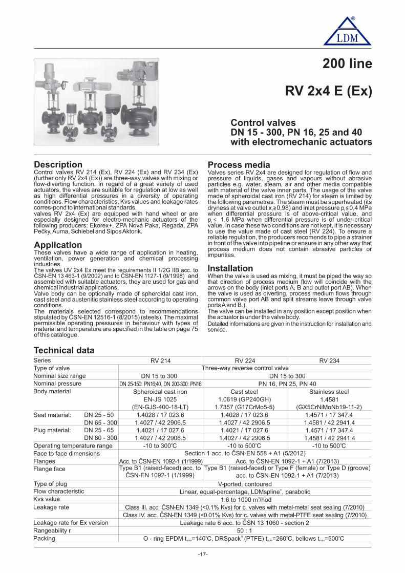
Control and Shut-off valvesDN 15 - 400, PN 16, 25 and 40with electromechanic actuators
200 line
RV / UV 2x0 E (Ex)
DescriptionControl valves RV / UV 210 (Ex), RV / UV 220 (Ex) and RV / UV230 (Ex) [(further only RV / UV 2x0 (Ex)] are single-seatedvalves designed for regulation and shut-off of process flow.liquidIn regard of a great variety of used actuators, the valves aresuitable for regulation at low as well as high differential pressuresin a diversity of operating conditions. Flow characteristics, Kvsvalues and leakage rates correspond to international standards.Valves RV / UV 2x0 (Ex) are equipped with hand wheel or areespecially designed for electro-mechanic actuators of thefollowing producers: Ekorex+, ZPA Nová Paka, Regada, ZPAPečky, Schiebel,Auma, and Rotork.SiposAktorik
ApplicationThe valves series RV / UV 2x0 are designed for applications inheating, ventilation, power generation and chemicalprocessing industries. The valves RV / UV 2x0 Ex meet therequirements II 1/2G IIB dle ČSN-EN 13463-1 (9/2002) andČSN EN 1127-1 (9/1998), and in connection with suitableactuators, they are also designed for applications in gas andchemical industries. Valve body can be optionally made ofspheroidal cast iron, cast steel and stainless steel.The materials selected correspond to recommendationsstipulated by ČSN-EN -1 ( /20 ) (steels) and ČSN-EN12516 8 151503-3 (1/2002) (cast). The maximal permissible operatingpressures in behaviour with types of material and temperatureare specified in the table on page 7 of this catalogue.5
Process mediaValves series RV (UV) 2x0 are designed for regulation (RV 2x0)and shut-off (UV 2x0) of flow and pressure of liquids, gases andvapours without abrasive particles e.g. water, steam, air andother media compatible with material of the valve inner parts.The valves series RV /UV 2x0 Ex are also designed for controland shut-off of the flow and pressure of technical and fuel gasesand inflammable liquids. The usage of the valve made ofspheroidal cast iron (RV 210) for steam is limited by the followingpara-metres. The steam must be superheated (its dryness atvalve outlet x 0,98) and inlet pressure p 0,4 MPa when1 1
differential pressure is of above-critical value, and p 1,6 MPa1
when diffe-rential pressure is of under-critical value. In casethese two conditions are not kept, it is necessary to use thevalue made of cast steel (RV 220). To ensure a reliableregulation, the producers recomends to pipe a strainer in front ofthe valve into pipeline or ensure in any other way that processmedium does not contain abrasive particles or impurities.
>= >=>=
InstallationThe valve is to be piped the way so that the direction of mediumflow will coincide with the arrows on the body.The valve can be installed in any position except position whenthe actuator is under the valve body.Detailed informations are given in the instruction for installation andservice.
Face to face dimensions
Packing
Type of plugFlow charakteristicKvs valueLeakage rate
Leakage rate for Ex version
Connection flanges
RV / UV 210 (Ex) RV / UV 230 (Ex)Two-way, single-seated, control valve(shut-off)
Cast steelEN-JS 1018 1.4581
1.4571 / 17 347.41.4027 / 42 2906.5
1.4021 / 17 027.6 1.4571 / 17 347.41.4027 / 42 2906.5 1.4581 / 42 2941.4
Section 1 acc. to ČSN-EN 558-1+A1 (5/2012)Acc. to ČSN-EN 1092-1 + A1 (7/2013)
0.01 to 1600 m /hour3
Leakage rate 6 acc. to ČSN 13 3060 - section 2
O - ring EPDM t =14 , DRSpack (PTFE) t =26 , Exp. graphite, bellows t =50max max max0 C 0 C 0 Co o o�
RV / UV 220 (Ex)
Stainless steelSpheroidal cast iron1.0619 (GP240GH)
1.7357 (G17CrMo5-5)1.4028 / 17 023.6 1.4028 / 17 023.6
1.4027 / 42 2906.5 1.4581 / 42 2941.41.4021 / 17 027.61.4027 / 42 2906.5
-10 to 300 Co -10 to 500 Co -10 to 400 Co
Type B1 (raised-faced) acc. to
(EN-GJS-400-10-LT) (GX5CrNiMoNb19-11-2)
Rangeability r 50 : 1
SeriesType of valveNominal size rangeNominal pressureBody material
Seat material :DIN W.Nr./+ČSNPlug material :DIN W.Nr./+ČSN
Operating temperature range
V-ported, contoured, perforatedLinear, equal-percentage, LDMspline , parabolic, on - off�
Class III. acc. to ČSN-EN 1349 ( 0.1% Kvs) for c. valves with metal-metal seat sealing (7/2010)<Class IV. acc. to ČSN-EN 1349 ( 0.01% Kvs) for c. valves with metal-PTFE seat sealing (7/2010)<
Class IV. acc. to ČSN-EN 1349 ( 0.01% Kvs) for shut off valve (7/2010)<
Technical data
Flange faces
1.4021 / 17 022.6 1.4581 / 42 2941.41.4027 / 17 022.6DN 200 - 400DN 80 - 150DN 15 - 65DN 65 - 400DN 15 - 50
DN 15 to 400PN 16, 25, 40
DN 15 to 400DN 15-150: PN16;40, DN 200-400: PN16
Acc. to ČSN-EN 1092-1 (1/1999)Type B1 (raised-faced) or Type F (female) or Type D (groove)
ČSN-EN 1092-1 (1/1999) acc. to ČSN-EN 1092-1 + A1 (7/2013)

®
-9-
ST 0.1
ST 0
DN1515202020
1---
4.0
6.3
H 2 3 4 5
2516
40
2.5---
---
1.6---
---
1.0---
---
0.6---
---
60.4---
---
10.0
16.025.040.0
10.016.025.0
10.016.0
------------
---------------
---------------
100.0160.0250.0360.0
63.0100.0160.0250.0
40.063.0
100.0160.0
------------
------------
------------
25323240506580100125150
------
---4.0
2.5---
1.6---
1.0---
0.6---
2.5 1.6 ------ --- ---4.0 --- --- ---6.3
4.0--- --- ---6.3
40.0 25.063.0
70.25
---
---
---------------------------
------
------
ENB ENB
Zepadyn
ENC
� p
4.004.004.004.004.004.00
------------------
4.004.004.003.602.101.20
4.00---
4.003.902.301.40
0.730.450.270.18
0.860.560.360.25
6,3 kN
PTN 2.32 MIDI 660
ERC ENB
� p � p
4.00 4.004.00 4.004.00 4.004.00 4.004.00 4.004.00 4.00
--- ------ ------ ------ ------ ------ ---
4.00 4.004.00 4.002.61 3.491.62 2.190.93 1.270.53 0.74
4.00 4.00--- ---
2.92 3.811.87 2.441.12 1.460.68 0.89
--- ------ ------ ------ ---
--- ------ ------ ------ ---
3,2 kN 4,0 kN
PTN 2.20
ERB
� pmetal
4.004.004.004.003.774.00
PTFE
------------------
2.244.001.280.77------
2.65---
1.601.02------
------------
------------
2 kN
80.16
---
---
---------------------------
------
------
90.1---
---
---------------------------
------
------
25
Max. differential pressure p for valves PN 16 must be 1.6 MPa.�metal - version with metal - metal seat sealingPTFE - version with metal - PTFE seat sealing (is not applica-
ble to contoured plugs)Max. differential pressures specified in table apply to PTFE andO-ring packing. p for bellows must be consulted with the� max
producer. It applies to graphite packing as well especially whenrequired p value is close to max. values specified in table.��pmax values are set for the most unfavourable pressure ratioson the valve PN 40, but in concrete cases the real value�pmax
can be higher than values specified in the table above.
1) parabolic plug2) V-ported plug with linear characteristic, parabolic plug withequal-percentage, LDMspline and parabolic characteristic.®
3) valve with micro-throttling trim. Execution with Kvs 0.01 tom /hour0.063 is possible after agreement with the producer.3
Equal-percentage, LDMspline and parabolic characteristic®
available on condition : Kvs value 1.0Perforated plug available only with Kvs values in shadowedframes with the following restrictions:
- Kvs values 2.5 to 1.6 m /hour available with linear chara-3
cteristic only.- Perforated plug with Kvs value acc. to column No. 2
available with linear or parabolic characteristic only.
�=
Kvs [m /hour]3max max max max
AUMA
Rotork
SchiebelMIDI 660MIDI 660
Sipos
EA...,
� p
4.004.004.004.004.004.00
------------------
4.004.004.002.901.691.00
4.00---
4.003.151.881.15
------------
------------
5 kN
EZ...,EQ...,Sipos
max
1) 1) 1) 1) 1) 1) 3) 3)
1) 1) 1) 1)
2)
1) 1)
1)
1)
1)
2) 2)
1)
ST 0
EPK
� p
4.004.004.004.004.004.00
------------------
3.164.001.831.120.630.35
3.57---
2.151.380.820.50
------------
------------
2,5 kN
max
ST 1 Ex
EPJEPK
ST 0.1
EPLERD
PTN 6
Linear force
For further information onactuating, see actuators´catalogue sheets
Actuating (actuator)
Marking in valve specification No.
Kvs values and differential pressures of valves P DN 15 - 150[M a]
Linear force
For further information onactuating, see actuators´catalogue sheets
Actuating (actuator)
Marking in valvespecification No.
� p value is the valve max. differential pressure whenopen - close function is always guaranteed. In regard ofservice life of seat and plug, it is recommended so that
differential pressure would not exceed 1.6 MPa. Otherwiseit is suitable to use perforated plug or sealing surfaces ofseat and plug with a hard metal overlay.
max
metal PTFE metal PTFE metal PTFE metal PTFE metal PTFE
EPL
PTN 2.40
ERC
Kvs [m /hod]1 3 4 5
40.0 16.0 ------
------
100.0160.0250.0360.0
40.063.0
100.0160.0
------------
------------
6------------------
225.0
63.0100.0160.0250.0
40.0 25.063.0
7------------------
Modact MTR
ST 2
EPDEPM
------
------
2.541.621.030.71
2.661.721.120.78
16 kN
Modact MTN
EYA
------
------
2.361.500.960.66
2.481.611.040.73
15 kN
Zepadyn
ENC
3.822.30
4.002.45
1.460.920.580.39
1.581.020.660.46
10 kN
Modact Cont.
EYB
Modact MTR
EPD
3 � p� p� pmax max max
AUMA
Rotork
Schiebel
Sipos
EA...,EZ...,EQ...,ET...
3.822.30
4.002.45
1.460.920.580.39
1.581.020.660.46
10 kN� pmax
AUMA
Rotork
Schiebel
Sipos
EA...,EZ...,EQ...,ET...
metal PTFE
2.761.65
2.951.80
1.010.630.390.26
1.130.730.470.33
7,5 kN� pmax
PTN 6
ERD EA...,EZ...
Auma
Schiebel
Hand wheel
*)
Rxx
3.802.30
4.002.45
2.541.621.030.71
2.661.721.120.78
DN506580100125150
H
40
25
*) For DN 15 - 40 with hand wheelis p = 4.00 MPa.� max
metal PTFE metal PTFE metal PTFE metal PTFE metal PTFE
Zepadyn 671
PTN 7
ENEERG

®
-10-
AUMA
Schiebel
EA...EZ...
32 kN
Modact MTN
EPD
25 kN
AUMA
EA...
20 kN
Modact MTR
EYA
Schiebel
EZ...
Kvs [m /hod]3
Modact MTR
EPDEPM
16 kN
AUMA
Rotork
Schiebel
EMG
EA...EZ...EQ...ED...
15 kN
EMG
ED... EYBEPM
Modact Cont.
Hand wheel
Rxx
Kvs values and differential pressures �p P of valvesmax [M a]DN 200 - 400 with V-ported plugs (flow direction below plug)
Modact MTN
Modact Cont.
EYAEYB
Max. differential pressure p for valves PN 16 (PN 25) must be�1,6 MPa ( 2,5 MPa).
Max. differential pressures specified in table are valid for seatsealing metal-metal and hard metal overlay on sealing surf.
Kvs values and differential pressures �p P of valvesmax [M a]DN 200 - 400 with perforated plugs (flow direction above plug)
For further information onactuating, see actuators´catalogue sheets
Actuating (actuator)
1
Marking in valvespecification No.
3 4 5------
400630
------
8001000
250400630630
2
Linear force
160250400400
AUMA
Schiebel
EA...EZ...
0.770.55
0.860.63
0.460.26
0.530.30
32 kN
Modact MTN
EPD
0.560.39
0.650.46
0.330.18
0.390.22
25 kN
AUMA
0.410.27
0.500.35
0.230.12
0.290.16
20 kN
Modact MTR
EYA
Schiebel
Kvs [m /hod]3
Modact MTR
EPD
0.290.18
0.370.26
0.150.08
0.210.11
16 kN
AUMA
SchiebelEMG
EA...EZ...ED...EYA
graph. PTFE
0.260.16
0.340.23
0.130.07
0.190.10
15 kN
EMG
EYB
Modact Cont.
Hand wheel
Rxx
DN H
80
Modact MTN
Modact Cont.
EYB
1.000.750.600.35
Ds200
250330
230100160250250
Max. differential pressures specified in table apply to PTFEand graphite packing.Max. differential pressure p for valves PN 16 (PN 25) must be�1,6 MPa ( 2,5 MPa).
It is not possible to delivery perforated plugs for Kvs acc. to thecolumn No.1, for Kvs acc. to the column No.2 it is possible onlywith linear or parabolic characteristic. For another columnswithout limitation.
200
300400
25080
80100
packing packingpacking packing packing packing
packing packingpacking packing packing packing
� p value is the valve max. differential pressure whenopen - close function is always guaranteed. In regard ofservice life of seat and plug, it is recommended so that
differential pressure would not exceed 1.6 MPa. Otherwiseit is suitable to use perforated plug or sealing surfaces ofseat and plug with a hard metal overlay.
max
Linear force
For further information onactuating, see actuators´catalogue sheets
Actuating (actuator)
Marking in valvespecification No.
graph. PTFE graph. PTFE graph. PTFE graph. PTFE graph. PTFE
ST 2 *)
ST 2 *)*) max. DN 300
EA...EZ...ED...
*) max. DN 300
ST 2 *)
ST 2 *)
EPM
Ds - Seat diameter
Ds - Seat diameter
Zepadyn 671*)
PTN 7 *)
Zepadyn 671*)
PTN 7 *)
ENEERG ENE
ERG
1 3 4 5------
---400
570------
800
------
630---
250------
400------
2160------
250------
3.141.39
3.471.54
0.771.330.740.55
0.861.500.840.63
2.311.01
2.641.17
0.560.950.520.39
0.651.130.620.46
1.710.75
2.050.90
0.410.680.370.27
0.500.860.470.35
1.240.53
1.580.68
0.290.470.250.18
0.370.640.350.26
grafit PTFE
1.120.48
1.460.63
0.260.410.220.16
0.340.590.320.23
DN
200
H
80
grafit PTFE grafit PTFE grafit PTFE grafit PTFE grafit PTFE
--- 800
400
---0.740.55
0.840.63
0.520.39
0.620.46
0.370.27
0.470.35
0.250.18
0.350.26
0.220.16
0.320.23
250 80
30080
400100
1000---
---
------
1000
---
---
0.46
0.46
0.53
0.53
0.33
0.33
0.39
0.39
0.23
0.23
0.29
0.29
0.15
0.15
0.21
0.21
0.13
0.13
0.19
0.191600 --- --- 0.26 0.300.18 0.220.12 0.160.08 0.110.07 0.10
4.001.801.001.801.000.75
1.00
0.60
0.600.35
Ds100
200150200230
150
200230250150
250330
630------
------
100------
160------
250
------
------
--- ---150 1.33 1.500.95 1.130.68 0.860.47 0.640.41 0.59 1.80
0.75
--- --- ---
--- ---400
0.74 0.840.52 0.620.37 0.470.25 0.350.22 0.32 1.00200 630250--- 1.33 1.500.95 1.130.68 0.860.47 0.640.41 0.59 1.80
--- ---
--- ---

®
-11-
Dimensions and weights of valves made of spheroidal cast iron
Dimensions and weights of valves made of cast steel and steinless steelfor the type RV / UV 220 (Ex), RV /UV 230 (Ex) DN 15 - 150
for the type RV / UV 210 (Ex), DN 15 - 150
with regard of the standard previously in force, there is anoption to have the number of onnection bolts as stipulatedc
in ČSN-EN 1092-1- for valve with bellows packing
m - weight to be added to weight of valve equipped withbellows packing
v
1)
#)
kg3.53.53.53.53.54
DN
152025324050
mm mm mm mm65 130 51 9075 150 54 9085 160 58 100
100 180 70 100110 200 75 100125 230 85 132
kg4.55.56.58914
mm
4
mm152025324050
mm
65
mm
M10x1
mm mm mm257 220 387257 220 387267 230 397267 230 397267 230 397339 262 469
44.54.555
6580100125150
145 290 93 132160 310 105 164180 350 118 164210 400 135 183240 480 150 200
1826385878
8
6580
100125150
339 262 469482 294 612482 294 612501 313 631518 330 648
PN 16 PN 40 PN 16, PN 40
14
19
23
4
8
M16x1
,5
D L V V md n
14
19
mm
23
28
d n D D D V V V mmm95
105115140150165185200220250285
D1 2
mm465665768499118132156184211
D3
95105115140150165
mm
185200235270300
D1
mm657585
100110125145160190220250
D2
mm465665768499118132156184211
D3 4 5
#
1 2 2 3 3
#
v
#
mm141616181919191919
23.526
a
kg3.53.53.53.53.54
DN
152025324050
mm mm mm mm65 130 51 9075 150 54 9085 160 58 100
100 180 70 100110 200 75 100125 230 85 132
kg5.56.58
9.51121
mm
4
mm152025324050
mm
65
mm
M10x1
mm mm mm257 220 387257 220 387267 230 397267 230 397267 230 397339 262 469
44.54.555
6580100125150
145 290 93 132160 310 105 164180 350 118 164210 400 135 183240 480 150 200
27404982100
8
6580
100125150
339 262 469482 294 612482 294 612501 313 631518 330 648
PN 16 PN 40 PN 16, PN 40
14
18
22
4
8
M16x1
,5
D L V V md n
14
18
mm
22
26
d n D D D V V V mmm95
105115140150165185200220250285
D1 2
mm4558687888
102122138158188212
D3
95105115140150165
mm
185200235270300
D1
mm657585
100110125145160190220250
D2
mm4558687888
102122138162188218
D3 4 5
#
1 2 2 3 3
#
v
#
mm1618181818202224242628
a
41)

-12-
®
Dimensions and weights of valves made of spheroidal cast iron
Dimensions and weights of valves made of cast steel and steinless steelfor the type RV / UV 2x0 (Ex), DN 200 - 400
for the type RV / UV 210 (Ex), DN 200 - 400
DNmm mmmm mm
200250300400
340 268295405 320355460 378410580 490525 16
PN 16
22
D DD d n1 2 3
12
mm24262832
a
26
30
mm mmmm mm360 278310425 335370485 395430620 505550
16
26
D DD d n1 2 3
12
mm30323440
a
30
36
PN 25
mm mmmm mm375 285320450 345385515 410450660 535585
16
D DD d n1 2 3
12
mm34384250
a
33
39
30
PN 40
DNmm mm
200250300400
200250300400
PN 16, 25, 40D M L
mm
M20x1.5
D5
mm203253296382
150
mm mmmm262 422346 506395 555512
160
672 100
Hkg
220
5701170
mmm6007308501100
V V1 2 V V3 4
39080
mm
DNmm mmmm mm
200250300400
340 266295405 319355460 370410580 480525 16
PN 16
23
D DD d n1 2 3
12
mm2022
24.528
a
28
31
mm mm200250300
M20x1.5
400
D M LmmD5
mm203253296382
150
mm mmmm262 422346 506395 555512
160
672 100
Hkg
141
364747
mmm6007308501100
V V1 2 V V3 4
25980
mm

®
-13-
Control valvesDN 25 - 00, PN 16 and 406with electromechanic actuators
200 line
RV 2x2 E (Ex)
Process mediaValves series RV 2x2 are designed for regulation of flow andpressure of liquids, gases and vapours without abrasive particlese.g. water, steam, air and other media compatible with material ofthe valve inner parts. The valves series RV 2x2 Ex are alsodesigned for control and shut-off of the flow and pressure oftechnical and fuel gases and inflammable liquids. The usage of thevalve made of spheroidal cast iron (RV 212) for steam is limited bythe following parametres. The steam must be superheated (itsdryness at valve outlet x 0,98) and inlet pressure p 0,4 MPawhen differential pressure is of above-critical value, andp 1,6 MPa when differential pressure is of under-critical value. Incase these two conditions are not kept, it is necessary to use thevalue made of cast steel (RV 222). To ensure a reliable regulation,the producers recomends to pipe a strainer in front of the valve intopipeline or ensure in any other way that process medium does notcontain abrasive particles or impurities.
DescriptionControl valves RV 212 (Ex), RV 222 (Ex) and RV 232 (Ex)[further only RV 2x2 (Ex)] are single-seated valves withpressure-balanced plug designed for regulation of processliquids flow. In regard of used actuators, the valves are suitablefor regulation at high differential pressures with low-linear-force actuators. Flow characteristics, Kvs values and leakagerates correspond to international standards.Valves RV 2x2 (Ex) are equipped with hand wheel or areespecially designed for electro-mechanic actuators of thefollowing producers: ZPA Nová Paka, Ekorex+, Regada, ZPAPečky,Auma, Schiebel .and SiposAktorik
ApplicationThe valves series RV 2x2 are designed for applications inheating, ventilation, power generation and chemical pro-cessing industries. The valves RV 2x2 Ex meet the require-ments II 1/2G IIB dle ČSN-EN 13463-1 (9/2002) and ČSN EN1127-1 (9/1998), and in connection with suitable actuators,they are also designed for applications in gas and chemicalindustries. Valve body can be optionally made of spheroidalcast iron, cast steel and stainless steel.The materials selected correspond to recommendations stipu-lated by ČSN-EN (steels) and ČSN-EN 1503-312516-1 (8/2015)(1/2002) (cast). The maximal permissible operating pressures inbehaviour with types of material and temperature are specified inthe table on page of this catalogue.75
Technical data
>=
1>= >=1
Packing
Leakage rate for Ex version
RV 212 (Ex) RV 232 (Ex)Two-way, single-seated, control valve with pressure-balanced plug
DN 25 to 600PN 16, PN 25, PN 40
Cast steelEN-JS 1025 1.4581
1.4571 / 17 347.41.4027 / 42 2906.5
1.4021 / 17 027.6 1.4571 / 17 347.41.4027 / 42 2906.5 1.4581 / 42 2941.4
Section 1 acc. to ČSN-EN 558-1 + A1 (5/2012)
4 to 4000 m /hour3
Class III. acc. ČSN-EN 1349 (<0.1% Kvs) for c. valves with metal-metal seat sealing (7/2010)
Leakage rate 6 acc. to ČSN 13 3060 - section 2
O - ring EPDM t =140 C, DRSpack (PTFE) t =260 C, Exp. graphite, bellows t =500 Cmax max max
o ® o o
RV 222 (Ex)
Stainless steelSpheroidal cast iron1.0619 (GP240GH)
1.7357 (G17CrMo5-5)1.4028 / 17 023.6 1.4028 / 17 023.6
1.4027 / 42 2906.5 1.4581 / 42 2941.41.4021 / 17 027.61.4027 / 42 2906.5
-10 to 260 Co -10 to 500 Co -10 to 500 Co
V-ported, perforatedLinear, equal-percentage, LDMspline , parabolic®
Class IV. acc. ČSN-EN 1349 (<0.01% Kvs) for c. valves with metal-PTFE seat sealing (7/2010)
(EN-GJS-400-18-LT) (GX5CrNiMoNb19-11-2)
Rangeability r 50 : 1
SeriesType of valveNominal size rangeNominal pressureBody material
Seat material:
Face to face dimensions
Type of plugFlow characteristicKvs value
Flanges
DN 25 - 50DN 65 - 400
Plug material: DN 25 - 65DN 80 - 150
Operating temperature range
Flange face
Leakage rate
1
DN 25-150: PN16;40, DN 200-400: PN16
DN 25 to 400
1.4021 / 17 022.6 1.4581 / 42 2941.41.4021 / 17 022.6
Acc. to ČSN-EN 1092-1 + A1 (7/2013)Type B1 (raised-faced) acc. toAcc. to ČSN-EN 1092-1 (1/1999)
Type B1 (raised-faced) or Type F (female) or Type D (groove)ČSN-EN 1092-1 (1/1999) acc. to ČSN-EN 1092-1 + A1 (7/2013)
DN 200 - 006
InstallationThe valve is to be piped the way so that the direction of mediumflow will coincide with the arrows on the body.The valve can be installed in any position except position whenthe actuator is under the valve body.Detailed informations are given in the instruction for installation andservice.

®
-14-
Kvs values and differential pressures �p P of valves DN 25 - 150max [M a]
Perforated plug available only with Kvs values in shadowedframes with the following restrictions:
- Perforated plug with Kvs value acc. to column No. 2 availablewith linear or parabolic characteristic only.
Max. differential pressure p for valves PN 16 must be 1.6 MPa.�
1) linear characteristic onlyValves RV 2x2 can be optionally assembled with all theactuators specified in catalogue sheet RV / UV 2x0.Max. differential pressures specified in table apply to PTFE andO-ring packing. p for bellows must be consulted with the�producer.
Kvs [m /hour]3
max
Linear force
For further informationon actuating,see actuators´catalogue sheets
Marking in valve spec.No.
Actuating (actuator)
� p value is the valve max. differential pressure whenopen - close function is always guaranteed. In regard ofservice life of seat and plug, it is recommended so that
differential pressure would not exceed 1.6 MPa. Otherwiseit is suitable to use perforated plug or sealing surfaces ofseat and plug with a hard metal overlay.
max
DN 325
Modact MTR
ST 2
EPDEPM
� p
10.016.0
40.063.0
100.0160.0
3240506580100125150
4.0
25.0
1
16.025.040.0
100.0160.0250.0360.0
10.0
63.0
6.3---------------
16 kN
4.004.004.004.00
Modact Cont.
Modact MTN
EYA
� p
---------------
15 kN
EYB
4.004.004.004.00
ST 1 Ex
EPJ
Zepadyn
ENC
� p
4.004.004.004.004.00
6,3 kN
4.004.004.004.00
PTN 2.20
ERB
� p
4.004.004.00------
2 kN
------------
H
25
40
16
max max
Rotork
AUMA
Sipos
SchiebelMIDI 660
EA...,
� p
---------
4.004.00
5 kN
EZ...,ENBEQ...,ET...
4.004.004.004.00
max max max
2
10.016.025.0
63.0100.0160.0250.0
6.3
40.0
1) 1)
1)
ST 0
EPK
� p
4.004.004.004.004.00
2,5 kN
------------
max
ST 0.1
EPL
PTN 6
ERD
4
10.0
25.040.063.0
100.0
2.5
16.0
4.0
1)
1)
5
16.025.040.063.0
1.6
10.0
2.5
1)
1)
6.3 1) 4.06.3
1)
1)
Hand Wheel
Rxx
� pmax
4.004.004.004.004.004.004.004.004.00
Kvs values and differential pressures �p P of valves DN 200 - 600max [M a]
For further informationon actuating,see actuators´catalogue sheets
� p value is the valve max. differential pressure whenopen - close function is always guaranteed. In regard ofservice life of seat and plug, it is recommended so that
differential pressure would not exceed 1.6 MPa. Otherwiseit is suitable to use perforated plug or sealing surfaces ofseat and plug with a hard metal overlay.
max
Max. differential pressures specified in table apply to PTFEand graphite packing.Max. differential pressure p for valves PN 16 (PN 25) must be�1,6 MPa ( 2,5 MPa).
It is not possible to delivery perforated plugs for Kvs acc. to thecolumn No.1, for Kvs acc. to the column No.2 it is possible onlywith linear or parabolic characteristic. For another columnswithout limitation.
Zepadyn 671
PTN 7
ENEERG
Actuacting (actuator)
1
Marking in valve spec.No.
3 4 5570800
400630
1000
4000
800
2500
250400630
1600
2
Osová síla
160250400
1000
Modact MTN
EPD
25 kN
Modact MTR
EYA
Kvs [m /h]3
Modact MTR
EPD
16 kN
AUMA
SchiebelSipos
EA...EZ...ET...EYA
15 kN
EYB
Modact Cont.
DN H
80
Modact MTN
Modact Cont.
EYB
Ds200
250
500
230100160250
630
200
300
600
25080
80
120
packing
AUMA
EA...
20 kN
Schiebel
EZ...
Sipos
ET...
packingpacking packing
ST 2
ST 2 *)
EPM
EPM
---4.004.00
---
Hand wheel
Rxx
4.004.004.004.00
packing
---4.004.004.00
4.00------
---
4.00---------
ENEERG ENE
ERG
Schiebel
EA...
32 kN
AUMA
EZ...
packing
---------
4.001600 1000 630 400330 250400 100 4.00--- ---
--- --- ---
graphitePTFE
*) max. DN 300Ds - Seat diameter
Zepadyn 671
PTN 7 Zepadyn 671*)
PTN 7 *)
graphitePTFE graphitePTFE graphitePTFE graphitePTFEgraphitePTFE
Sipos
ET...

®
-15-
Dimensions and weights of valves made of spheroidal cast ironfor the type RV 212 (Ex) DN 25 - 150
Dimensions and weights of valves made of cast steel and steinless steelfor the type RV 222 (Ex), RV 232 (Ex) DN 25 - 150
with regard of the standard previously in force, there is anoption to have the number of onnection bolts as stipulatedc
in ČSN-EN 1092-1- for valve with bellows packing
m - weight to be added to weight of valve equipped withbellows packing
v
1)
#)
kg3.53.53.54
DN
25324050
mm mm mm mm kg65 115 160 58 100 776 140 180 70 100 8.584 150 200 75 100 8.599 165 230 85 132 14.5
mm mm mmmm85 14 1665
100 1876110 1984125 19 1999
mm mm25324050
mm mm
M10x1
mm mm mm267 230 397267 230 397267 230 397339 262 469
44.54.555
6580100125150
118 185 290 93 132 18.5132 200 310 105 164 27.5156 235 350 118 164 39184 270 400 135 183 60211 300 480 150 200 81
145 19118160 19132190 23 19156220 23.5184250
2826211
6580
100125150
65 339 262 469482 294 612482 294 612501 313 631518 330 648
PN 16 PN 40 PN 16, PN 40
M16x1
,5
D L V V mmm14
19
23
d
4
8
n D D aD d
4
8
n D D D V V V mmm115140150165185200220250285
D1
mm85
100110125145160180210240
D2 3 1 2 3 4 5
#
1 2 2 3 3
#
v
#
kg3.53.53.54
DN
25324050
mm mm mm mm kg68 115 160 58 100 8.578 140 180 70 100 1088 150 200 75 100 10
102 165 230 85 132 21
mm mm mmmm85 14 1868
100 1878110 1888125 18 20102
mm mm25324050
mm mmM
10x1
mm mm mm267 230 397267 230 397267 230 397339 262 469
44.54.555
6580100125150
122 185 290 93 132 27138 200 310 105 164 42158 235 350 118 164 50188 270 400 135 183 84212 300 480 150 200 103
145 22122160 24138190 22 24162220 26188250
2628218
6580
100125150
65 339 262 469482 294 612482 294 612501 313 631518 330 648
PN 16 PN 40 PN 16, PN 40
M16x1
,5D L V V m
mm14
18
22
d
4
8
n D D aD d
4
8
n D D D V V V mmm115140150165185200220250285
D1
mm85
100110125145160180210240
D2 3 2 3 4 5
#
1 2 2 3 3
#
v
#
1)4
1

Dimensions and weights of valves made of spheroidal cast ironfor the type RV 212 (Ex), DN 200 - 400
Dimensions and weights of valves made of cast steel and steinless steelfor the type RV 222, 232 (Ex), DN 200 - 600
®
-16-
DNmm mmmm mm
200250300400
340 266295405 319355460 370410580 480525 16
PN 16
23
D DD d n1 2 3
12
mm2022
24.528
a
28
31
mm mm200250300
M20x1.5
400
D M LmmD5
mm203253296382
150
mm mmmm262 422346 506395 555512
160
672 100
Hkg
153
390790
mmm6007308501100
V V1 2 V V3 4
26480
mm
DNmm mmmm mm
200250300
600
340 268295405 320355460 378410
840 725770 20
PN 16
22
D DD d n1 2 3
12
mm242628
54
a
26
36
mm mmmm mm360 278310425 335370485 395430
845 720770
16
26
D DD d n1 2 3
12
mm303234
58
a
30
39
PN 25
mm mmmm mm375 285320450 345385515 410450
890 735795
16
D DD d n1 2 3
12
mm343842
72
a
33
48
30
PN 40
DNmm mm
200250300400
200250300
M20x1.5
400
PN 16, 25, 40D M L
mmD5
mm203253296382
150
mm mmmm262 422346 506395 555512
160
672 100
Hkg
232
5961213
mmm6007308501100
V V1 2 V V3 4
39580
mm
400 580 490525 16 3230 620 505550 4036 660 535585 503920
600 580 590 675 885 120 35001450
20
M30x2 300 210
®
-17-
Control valvesDN 15 - 0, PN 16 and 4030 , 25with electromechanic actuators
200 line
RV 2x4 E (Ex)
InstallationWhen the valve is used as mixing, it must be piped the way sothat direction of process medium flow will coincide with thearrows on the body (inlet ports A, B and outlet port AB). Whenthe valve is used as diverting, process medium flows throughcommon valve port AB and split streams leave through valveportsAand B.).The valve can be installed in any position except position whenthe actuator is under the valve body.Detailed informations are given in the instruction for installation andservice.
DescriptionControl valves RV 214 , RV 224 and RV 234(Ex) (Ex) (Ex)(further only RV 2x4 ) are three-way valves with mixing or(Ex)flow-diverting function. In regard of a great variety of usedactuators, the valves are suitable for regulation at low as wellas high differential pressures in a diversity of operatingconditions. Flow characteristics, Kvs values and leakage ratescorres-pond to international standards.v (Ex)alves RV 2x4 are equipped with hand wheel or areespecially designed for electro-mechanic actuators of thefollowing producers: Ekorex+, ZPA Nová Paka, Regada, ZPAPečky,Auma, Schiebel and .SiposAktorik
ApplicationThese valves have a wide range of application in heating,ventilation, power generation and chemical processingindustries.The valves UV 2x Ex meet the requirements II 1/2G IIB acc. to4ČSN-EN 13 463-1 (9/2002) and to ČSN-EN 1127-1 (9/1998) andassembled with suitable actuators, they are used for gas andchemical industrial applications.Valve body can be optionally made of spheroidal cast iron,cast steel and austenitic stainless steel according to operatingconditions.The materials selected correspond to recommendationsstipulated by ČSN-EN ( /20 ) (steels). The maximal12516-1 8 15permissible operating pressures in behaviour with types ofmaterial and temperature are specified in the table on page 75of this catalogue.
Technical data
Process mediaValves series RV 2x4 are designed for regulation of flow andpressure of liquids, gases and vapours without abrasiveparticles e.g. water, steam, air and other media compatiblewith material of the valve inner parts. The usage of the valvemade of spheroidal cast iron (RV 214) for steam is limited bythe following parametres. The steam must be superheated (itsdryness at valve outlet x 0,98) and inlet pressure p 0,4 MPawhen differential pressure is of above-critical value, andp 1,6 MPa when differential pressure is of under-criticalvalue. In case these two conditions are not kept, it is necessaryto use the value made of cast steel (RV 224). To ensure areliable regulation, the producers recomends to pipe a strainerin front of the valve into pipeline or ensure in any other way thatprocess medium does not contain abrasive particles orimpurities.
>=1
>= >=1 1
Packing
Leakage rate for Ex version
RV 214 RV 234Three-way reverse control valve
DN 15 to 300PN 16, PN 25, PN 40
Cast steelEN-JS 1025 1.4581
1.4571 / 17 347.41.4027 / 42 2906.5
1.4021 / 17 027.6 1.4571 / 17 347.41.4027 / 42 2906.5 1.4581 / 42 2941.4
Section 1 acc. to ČSN-EN 558 + A1 (5/2012)
1.6 to 1000 m /hod3
Class III. acc. ČSN-EN 1349 (<0.1% Kvs) for c. valves with metal-metal seat sealing (7/2010)
Leakage rate 6 acc. to ČSN 13 1060 - section 2
O - ring EPDM t =14 , DRSpack (PTFE) t =26 , bellows t =50max max max0 C 0 C 0 Co o o
RV 224
Stainless steelSpheroidal cast iron1.0619 (GP240GH)
1.7357 (G17CrMo5-5)1.4028 / 17 023.6 1.4028 / 17 023.6
1.4027 / 42 2906.5 1.4581 / 42 2941.41.4021 / 17 027.61.4027 / 42 2906.5
-10 to 300 Co -10 to 500 Co -10 to 500 Co
V-ported, contouredLinear, equal-percentage, LDMspline , parabolic�
Class IV. acc. ČSN-EN 1349 (<0.01% Kvs) for c. valves with metal-PTFE seat sealing (7/2010)
®
(EN-GJS-400-18-LT) (GX5CrNiMoNb19-11-2)
Rangeability r 50 : 1
SeriesType of valveNominal size rangeNominal pressureBody material
Seat material:
Face to face dimensions
Type of plugFlow characteristicKvs value
Flanges
DN 25 - 50DN 65 - 030
Plug material: DN 25 - 65DN 80 - 030
Operating temperature range
Flange face
Leakage rate
DN 15 to 300DN 25-150: PN16;40, DN 200-300: PN16
Acc. to ČSN-EN 1092-1 (1/1999)Type B1 (raised-faced) acc. to
ČSN-EN 1092-1 (1/1999)
Acc. to ČSN-EN 1092-1 + A1 (7/2013)Type B1 (raised-faced) or Type F (female) or Type D (groove)
acc. to ČSN-EN 1092-1 + A1 (7/2013)

®
- -18
Max. differential pressures specified in table apply to PTFE andO-ring packing. p for bellows must be consulted with the� max
producer. It applies to graphite packing as well especially whenrequired p value is close to max. values specified in table.�
1) parabolic plug in straight way, V-ported plug in angle way2) V-ported plug in angle way, in straight way V-ported plug forlinear characteristic and for equal-percentage chara-
cteristic parabolic plug.Bellows packing can be used for DN 15 and 20.Max. differential pressure p for valves PN 16 must be 1.6 MPa.�metal - version with metal - metal seat sealingPTFE - version with metal - PTFE seat sealing (is not
applicable to contoured plugs)
Kvs values and differential pressures
�p value is the valve max. differential pressure whenmax
open - close function is always guaranteed. In regard ofservice life of seat and plug, it is recommended so that
differential pressure would not exceed 1.6 MPa. Otherwiseit is suitable to use perforated plug or sealing surfaces ofseat and plug with a hard metal overlay.
DN1520253240506580100125150
Zepadyn
ENC
� p
4.004.00
------
4.004.003.602.101.20
4.004.003.902.301.40
0.730.450.270.18
0.860.560.360.25
6,3 kN
PTN 2.32
ERC
� p
4.004.00
------
4.002.611.620.930.53
4.002.921.871.120.68
------------
------------
3,2 kN
PTN 2.20
ERB
� p
4.003.77
metal PTFE
------
2.241.280.77------
2.651.601.02------
------------
------------
2 kN
H
16
40
25
max max max
AUMA
Rotork
SchiebelMIDI 660 MIDI 660
SiposEA...,
� p
4.004.00
------
4.004.002.901.691.00
4.004.003.151.881.15
------------
------------
5 kN
EZ...,ENB ENBEQ...,ET...
max
11)4.0
6.310.016.025.040.0
100.0160.0250.0360.0
63.0
1)
22.5 1)
10.016.025.0
63.0100.0160.0250.0
4.06.3
40.0
1)
2)
31)1.6
10.016.0
40.063.0
100.0160.0
2.54.06.3
25.0
1)
2)
2)
AUMA
Schiebel
Rotork
Sipos
EA...EZ...EQ...ET...
2.761.65
2.951.80
1.010.630.390.26
1.130.730.470.33
7,5 kN� pmax
MIDI 660
ENB
� p
4.004.00
------
4.003.492.191.270.74
4.003.812.441.460.89
---------
---------
4,0 kN
max
ST 0
EPK
� p
4.004.00
------
3.161.831.120.630.35
3.572.151.380.820.50
------------
------------
2,5 kN
max
ST 0
EPK
ST 1 EX
EPJ
ST 0.1
EPL
PTN 6
ERD
ST 0.1
EPL
PTN 2.40
ERC
--- ---------------
------------
Hand wheel
Rxx
� pmax
3.82.3
4.02.45
2.541.621.030.71
2.661.721.120.78
4.04.04.04.04.0
Marking in valvespecification No.
Actuating(actuator)
Kvs [m /h]3
Linear force
For furtherinformation onactuating,see actuators´catalogue sheets
metal PTFE metal PTFE metal PTFE metal PTFE metal PTFE metal PTFE metal PTFE
DN506580100125150
Modact MTR
ST 2
EPDEPM
------
------
2.541.621.030.71
2.661.721.120.78
16 kN
EYAEYBEA...EZ...EQ...ET...
------
------
2.361.500.960.66
2.481.611.040.73
15 kN
Modact Cont.
Modact MTN
AUMA
Schiebel
Rotork
Sipos
� p� pmax max
Zepadyn
PTN 6
ENCERD
metal PTFE
3.822.30
4.002.45
1.460.920.580.39
1.581.020.660.46
10 kN� pmax
200 0.37 ---0.34 ------ ---
H
40
25
80
AUMA
Schiebel
Sipos
EA...EZ...ET...
------
------
------------
------------
20 kN� pmax
0.50 ---
Modact Cont.
Modact MTN
Modact MTR
ST 2
EYAEYBEPDEPM
------
------
------------
------------
25 kN� pmax
---0.65250300
Auma
Schiebel
EA...EZ...
------
------
------------
------------
32 kN� pmax
---0.860.25 ---0.23 ------ --- 0.35 --- ---0.46 ---0.62
140.0
100.0160.0250.0360.0
63.0
570.0800.0
1000.0
225.0
63.0100.0160.0250.0
40.0
400.0630.0800.0
316.0
40.063.0
100.0160.0
25.0
250.0400.0630.0 0.21 ---0.19 ------ --- 0.29 --- ---0.39 ---0.53
Auma
Schiebel
Rotork
Sipos
Modact MTR
EA...EZ...EQ...ET...EPD
3.822.30
4.002.45
1.460.920.580.39
1.581.020.660.46
10 kN� pmax
0.19 ---0.11 ---0.09 ---
Hand wheel
� pmax
0.600.751.0
---------
---------
RxxMarking in valvespecification No.
Actuating(actuator)
Kvs [m /h]3
Linear force
For furtherinformation onactuating,see actuators´catalogue sheets
metal PTFE metal PTFE metal PTFE metal PTFEmetal PTFE metal PTFE metal PTFE
Zepadyn 671
PTN 7 Zepadyn 671
PTN 7
ENEERG ENE
ERG

®
- -19
Dimensions and weights spheroidal cast ironof valves made offor the types RV 214 (Ex), DN 15 - 150
Dimensions and weights of valves made of cast steel and steinless steelfor the types RV 224 (Ex), RV 234 (Ex) DN 15 - 150
RV 2x4 DN 15 to 150
with regard of the standard previously in force, there is anoption to have the number of onnection bolts as stipulatedc
in ČSN-EN 1092-1- for valve with bellows packing
m - weight to be added to weight of valve equipped withbellows packing
v
1)
#)
kg3.53.53.53.53.54
DN
152025324050
mm mm mm mm65 130 110 6775 150 115 6785 160 130 72
100 180 135 72110 200 140 72125 230 175 92
kg5.56.58.310.51217
mm
4
mm152025324050
mm
65
mm
M10x1
mm mm mm--- 197 ------ 197 ---
239 202 369239 202 369239 202 369299 222 429
44.54.555
6580100125150
145 290 180 92160 310 220 123180 350 230 123210 400 260 151240 480 290 151
2231446594
8
6580
100125150
299 222 429441 253 571441 253 571469 281 599469 281 599
PN 16 PN 40 PN 16, PN 40
14
19
23
4
8
M16x1
,5
D L V V md n
14
19
mm
23
28
d n D D D V V V mmm95
105115140150165185200220250285
D1 2
mm465665768499118132156184211
D3
95105115140150165
mm
185200235270300
D1
mm657585
100110125145160190220250
D2
mm465665768499118132156184211
D3 4 5
#
1 2 2 3 3
#
v
#
mm141616181919191919
23.526
a
kg3.53.53.53.53.54
DN
152025324050
mm mm mm mm65 130 110 6775 150 115 6785 160 130 72
100 180 135 72110 200 140 72125 230 175 92
kg67
9.512
13.524
mm
4
mm152025324050
mm
65
mm
M10x1
mm mm mm--- 197 ------ 197 ---
239 202 369239 202 369239 202 369299 222 429
44.54.555
6580100125150
145 290 180 92160 310 220 123180 350 230 123210 400 260 151240 480 290 151
31435590120
8
6580
100125150
299 222 429441 253 571441 253 571469 281 599469 281 599
PN 16 PN 40 PN 16, PN 40
14
18
22
4
8
M16x1
,5
D L V V md n
14
18
mm
22
26
d n D D D V V V mmm95
105115140150165185200220250285
D1 2
mm4558687888
102122138158188212
D3
95105115140150165
mm
185200235270300
D1
mm657585
100110125145160190220250
D2
mm4558687888
102122138162188218
D3 4 5
#
1 2 2 3 3
#
v
#
mm1618181818202224242628
a
41)

®
-20-
Dimensions and weights spheroidal cast ironof valves made offor the type RV 214 (Ex), DN 200 - 300
Dimensions and weights of valves made of cast steel and steinless steelfor the types RV 224, 234 (Ex), DN 200 - 300
RV 2x4 DN 200 to 300
DNmm mmmm mm
200250300
340 266295405 319355460 370410
PN 16
23
D DD d n1 2 3
12
mm2022
24.5
a
28
mm mm200250300
M20x1.5
D M LmmD5
mm400480560
150
mm mmmm265 425360 520402 562
160
Hkg
162
410
mmm600730850
V V1 2 V V3 4
28080
mm
DNmm mmmm mm
200250300
340 268295405 320355460 378410
PN 16
22
D DD d n1 2 3
12
mm242628
a
26
mm mmmm mm360 278310425 335370485 395430 16
26
D DD d n1 2 3
12
mm303234
a
30
PN 25
mm mmmm mm375 285320450 345385515 410450 16
D DD d n1 2 3
12
mm343842
a
33
30
PN 40
DNmm mm
200250300
200250300
PN 16, 25, 40D M L
mmD5
mm400480560
150
mm mmmm265 425360 520402 562
160
Hkg
250
640
mmm600730850
V V1 2 V V3 4
42580
mm
M20x1.5

®
Ordering example: RV210 ENC 1423 L1 40/220- 650
®
®
®
®
Valve complete specification No. for ordering RV / UV 2x0 , RV 2x2 , RV 2x4(Ex) (Ex)
Control valve1. ValveShut-off valveValves made of spheroidal cast iron EN-JS 10252. SeriesValves made of cast steel 1.0619, 1.7357
Valves made of stainless steel 1.4581
Direct valve
Pressure -balanced valve
Mixing (diverting) valve
Electric actuator3. ActuatingHand wheel
Raised flange4. ConnectingFemale flange
Cast steel 1.06195. Body materialSphr. cast iron EN-JS 1025CrMo steel 1.7357Stainless steel 1.4581Other material on request
(-20 to 400 C)(-20 to 300 C)(-20 to 500 C)(-20 to 400 C)(Operating temperature ranges
are specified in parentheses)
Metal - metal6. Seat sealingSoft sealing (metal - PTFE)Hard metal overlay on sealing surfaces
From DN 25; t = 260 C
Exp. graphite
7. Packing
BellowsBellows with safety PTFE packing 6)
Bellows with safety Graphite packing
Parabolic - perforated plug
Linear8. Flow characteristicEqual-percentage in straight way
On-offLDMspline
ParabolicLinear - perforated plugEqual-percentage - perforated plug
Applicable to UV 2x0 only
Column No. acc. to Kvs value table9. KvsPN 1610. Nominal pressure PN
PN 40O - ring EPDM11. Max. operating temp. CDRSpack (PTFE), bellowsDRSpack (PTFE), bellowsExp. graphite; bellows
Exp. graphite; bellowsExp. graphite; bellowsDN12. Nominal size DN
Not applicable to RV 2x4
O - ring EPDMDRSpack (PTFE)
o
o
o
o
1)max
o 1)
6)
4)
5)
4)
5)
5)
5)
5)
5)
o
13. Execution
XXX-XXX/XX-X XX X X XX X XX X XXXRVUV
2 12 22 3
024
E X X
12
14789
123
5789
LR
UPDQZ
X16
40140220260300
400550
XXX
R X X
13
S
XX
ExNormalNon - explosive
-21-
3)Not applicable to Ex execution
3)
PN 25 (DN 200 to 600) 25
For marking of actuators in specification code, refer to table on page No. 75 of this catalogue
Only for DN 15 to 1506)
OxOxygen
Specifications of actuatorsacc. to table on page No. 75
2)
200 to 400For DNonly for PN 16
2)
Flange with groove 3
6)
Food industry execution Px
Balanced by graphite, metal - metal 578
Balanced by graphite, hard metal overlay
Blalanced with metal sealing cuff, hard metal overlay
Exp. graphite; bellows 315

®
-2 -2
Valves RV / UV 2x0 (Ex)Section of valve with V-ported plug Section of valve with perforated plug Section of valve with micro-throttling
system
Valves RV 2x2 (Ex)Section of pressure-balanced valvewith V-ported plug
Valve RV 2x4 (Ex)Section of three-way valve withV-ported plug
Section of pressure-balanced valvewith perforated plug

®
- -23
END
Electric actuator PIKO 524 65ZPA Nová Paka
Technical data
Marking in valve specification No.VoltageFrequencyPower consumptionControlNominal forceTravelEnclosureProcess medium max. temperatureAmbient temperatrure rangeAmbient humidity rangeWeight
END230 V or 24 VAC AC50 ± 2 HzMax. 9 VA3 - position control250 N when frequency 50 Hz10, 16 mmIP 54150 C-20 to 60 C5 - 100 % with condensation1,5 kg
Wiring diagram of actuator
M electromotorMO power switch for "OPEN" positionMZ power switch for "CLOSED"position
Voltage 230 V/50 Hz Voltage 24 V/50 Hz
Type PIKO 524 65.XXXX
Dimensions of actuator PIKO 524 65
Specification of actuator PIKO 524 65
X X X X524 65PIKOVoltage
Resetting speed
Connection dimensions
2 0 V / 50 Hz3
10 mm/min
LDM execution - max. draw bar stroke 16 mm
24 V / 50 Hz
20 mm/min
01
24
00
3
o
o
Travel 16

®
- -24
ERE
Electric actuators PTE 1Ekorex
Technical data
Marking in valve specification No.VoltageFrequencyPower consumptionControlNominal forceTravelEnclosureProcess medium max. temperatureAmbient temperature rangeAmbient humidity rangeWeight
ERE24 V AC50 ± 2 HzMax. 3,5 VAContinuous500 N10, 16 mmIP 54150 C-20 to 60 C5 - 100 % with condensation2 kg
Wiring diagram of actuator
Specification of actuator PTE 1
Dimensions of actuator PTE 1
PTE 1 X X X X Nominal force [N] Resetting speed [mm.min ]-1
012
0 - 10 V DC0 - 20 mA4 - 20 mA
Control signal galvanicly separatedfrom feeding voltage
0 10Draw bar stroke [mm]
Position Z upPosition Z down
24 V
0 - 10 V DC
0 500 10
1 16
Voltage24 V 50 Hz
01
Type PTE 1 XXXX
o
o
Controlamplifier
Max.Travel: 20
Controlamplifier

®
- -25
Electric actuator MIKRO 655ZPA Nová Paka
ENA
Technical data
ENA230 V or 24 V AC50/60 Hzmax. 6 (9) VA3 - position control, 0 - 10 V, 0(4) - 20 mA600 and 1800 N10, 16 mmIP 65Acc. to used valve-25 to 55 C10 - 100 % with condensation2,7 kg
Wiring diagrams
MO power switch for position "Open"MZ power switch for position "Closed"SO signalization switch for position "Open"SZ signalization switch for position "Closed"M motorC capacitorV transmitter RP 16 100I1 converter 4 - 20 mA for 2-wire conductor,
connection to measuring loop (feeding directly frommeasured signal)
3-position control, feeding voltage 230 V/50 Hz Control signal 0-10 V, 0(4)-20 mA, feeding voltage 230 V/50 Hz
3-position control, feeding voltage 24 V/50 Hz
Control signal 0-10 V, 0(4)-20 mA, feeding voltage 24 V/50 Hz
Mikro 655 xxx
o
Marking in valve specification No.VoltageFrequencyPower consumptionControlNominal forceTravelEnclosureProcess medium max. temperatureAmbient temperatrure rangeAmbient humidity rangeWeight
Type

®
-2 -6
Specification of actuator MIKRO 655
Dimensions of actuator MIKRO 655
230 V (50/60 Hz)24 V (50/60 Hz)0,61,210
1 resistance transmitter of 1002 resistance transmitter 100 - without OP1 and I1Coverter 4 - 20 mA - without OP1 and R2
162525Positioner 0-1 V, 0-10 V, 0(4)-20 mA - without R2 and I1Signalization switches SO and SZ
Feeding voltage AC
Resettingspeed[mm/min]
Linear force [kN]
Accessories
Basic execution: 3-position control, manual operating, limit switches for Open and Closed positions, without transmitterand connection elements.
MIKRO 655
Connection flange 25, coupling M8x1
X X X /12
12X 1X 21 32 3
OP1S1R1R2I1P2

®
-2 -7
Electric actuator MIDI 660ZPA Nová Paka
ENB
Technical data
ENB230 V or 24 V AC50/60 Hzmax. 12 (18) VA3 - position control, 0 - 10 V, 0(4) - 20 mA2000, 3200, 4000 N16, 25 mmIP 65Acc. to used valve-25 to 55 C10 - 100 % with condensation3,5 kg
Wiring diagrams
MIDI 660 XXX
o
KPO end position switch for position “Open”MO power switch for position "Open"MZ power switch for position "Closed"SO signalization switch for position "Open"SZ signalization switch for position "Closed"M motorC capacitorV transmitter RP 16 100I1 converter 4 - 20 mA for 2-wire conductor,
connection to measuring loop (feeding directly frommeasured signal)
3-position control, feeding voltage 230 V/50 Hz Control signal 0-10 V, 0(4)-20 mA, feeding voltage 230 V/50 Hz
3-position control, feeding voltage 24 V/50 Hz
Control signal 0-10 V, 0(4)-20 mA, feeding voltage 24 V/50 Hz
Marking in valve specification No.VoltageFrequencyPower consumptionControlNominal forceTravelEnclosureProcess medium max. temperatureAmbient temperatrure rangeAmbient humidity rangeWeight
Type

®
- -28
Specification of actuator MIDI 660
Dimensions of actuator MIDI 660
230 V (50/60 Hz)24 V (50/60 Hz)2,03,24,010
1 resistance transmitter 1002 resistance transmitters 100 - without OP1, I1 and C1
Manual operating outside the housing
16253232Positioner 0-1 V, 0-10 V, 0(4)-20 mASignalization switches SO and SZ
Feeding voltage AC
Resetting speed[mm/min]
Linear force [kN]
Accessories
Basic execution : 3-position control, manual operating, limit switches for Open and Closed positions, without transmitter andconnection elements.
MIDI 660
Connection flange for 65, coupling M10x1
X X X /12
134X 1X 2X 31 43 4
OP1S1R1R2
RK1P3
Converter 4 - 20 mA - without OP1, R2 and C1 I1Capacity transmitter CPT 1 - without R2 and I1 C1
POSITION
POSITION

®
- -29
ERA
Electric actuators PTN 1Ekorex
Technical data
Marking in valve specification No.VoltageFrequencyPower consumptionControlNominal forceTravelEnclosureProcess medium max. temperatureAmbient temperature rangeAmbient humidity rangeWeight
ERA230 V or 24 V AC50 ± 2 Hz8 VA3 - position control; 4 - 20 mA; 0 -10 V; 0 - 20 mA600 N, 1200 N10, 16 mmIP 54150 C-20 to 60 C5 - 100 % with condensation2 kg,5
Wiring diagram of actuator PTN 1
Type PTN 1 XXXXXXXX
o
o
AC 24V 50Hz
MOMZSOSZMCVI1
- power switch for "OPEN" position- power switch for "CLOSED" position- signalisation switch for "OPEN" position- signalisation switch for "CLOSED" position- motor- capacitor- resistance transmitter 100 Ω- resistance transmitter with convertor 4-20 mA - 2-wire execution
I2 - resistance transmitter with convertor - separate feeding 24V AC
WARNING: In case of using valves RV 102, RV 103is position "closed" up (switch MO)

®
-3 -0
Specification of actuator PTN 1
Dimensions of actuator PTN 1
Nominal force [N] Resetting speed [mm.min ]-1
Without equipment
Independent feeding voltage24 V
Flange with columns
Motor supply voltage (AC)
Number of microswitches
2 - wire connection
Resistance output signal
Draw bar stoke [mm]
Clutch M 8x1
PTN 1 X X X X X X X X
1 2 600 1625
02
230 V, 50 Hz24 V, 50 Hz
0 MO; MZ
0123456
Output 0 - 10 VOutput 0 - 20 mAOutput 4 - 20 mAOutput 4 - 20 mAOutput 0 - 100 1xOutput 0 - 100 2x
3 161
1 1 600 10
2 MO; MZ; SO; SZ
2 10
1 3 600
0
2 12 22 3
12001200
12001625
10
NOTE:Table applies to actuator with 3-position control.It is possible to supply actuator with control signal of 0 - 10 V, 0 - 20 mA, 4 - 20 mA(example of marking: PTN 1 - XX.XX.XX.XX / control signal 4 - 20 mA)

®
-3 -1
ERBERC
Electric actuators PTN 2Ekorex
Technical data
Marking in valve specification No.VoltageFrequencyPower consumptionControlNominal forceTravelEnclosureProcess medium max. temperatureAmbient temperature rangeAmbient humidity rangeWeight
ERB230 V + 6 %, -12 % or 24 V + 10 %, -15 % AC
50 HzMax. 1 VA9
3 - position control, (0) 4 - 20 mA, 0 - 10 V3200 N
Max. 25 mmIP 65
Acc. to used valve-20 to 60 C° (weather-resistant design -45 to 60°C)
5 to 100 % with condensation4 kg
Wiring diagram of actuator
ERC
2000 N
Type PTN 2 20. PTN 2 32.
MOMZSOSZ
MCVI1
- power switch for "OPEN" position- power switch for "CLOSED" position- signalisation switch for "OPEN" position- signalisation switch for "CLOSED" position
- motor- capacitor- resistance transmitter 100 Ω- resistance transmitter with convertor 4-20 mA - 2-wire execution
I2 - resistance transmitter with convertor - separate feeding 24V AC
KPO - terminal position switch for "OPEN" position
ERCPTN 2.40
4000 N
C1 - capacitive transmitter with convertor 4-20 mA
WARNING: In case of using valves RV 102, RV 103is position "closed" up (switch MO)

®
-3 -2
Specification of actuator PTN 2
Dimensions of actuator PTN 2
PTN 2 X X X X X X X X Nominal force [kN] Resetting speed [ mm/min ]
3 2 3,2 10, 16, 25, 3210, 16, 25
02
230 V, 50 Hz24 V, 50 Hz
Motor supply voltage (AC)
1
3
10
25Resetting speed [mm.min ]-1
0123456
Without equipmentOutput 0 - 10 VOutput 0 - 20 mAOutput 4 - 20 mAOutput 4 - 20 mAOutput 0 - 100 1xOutput 0 - 100 2x
Independent feeding 24 V
2 - wire connection
Resistance output signal
3 Flange with columns Pitch 100 mm02469
MO; MZMO; MZ; SO; SZMO; MZ; KPOMO; MZ; SO; SZ; KPOAccording to agreement
35
Number of microswitches
1625
Draw bar stroke [mm]
2 0 2 10, 16, 25, 32
2 16
1 Flange with columns
2 10
Pitch 70 mm Clutch M 8x1
Connection to valves RV 102, RV 103 Connection to valves RV / UV 2x0, RV 2x2, RV 2x4
-1
4 0 4
4 32
Clutch M 10x1
NOTE:Table applies to actuator with 3-position control.It is possible to supply actuator with control signal of 0 - 10 V, 0 - 20 mA (code /DMS 3), 4 - 20 mAs ručním ovládání vně skříně (/RO) nebo verzi se zvýšenou klimatickou odolností -45°C to 60°C (/KO)(example of marking: PTN 2 - XX.XX.XX.XX / control signal 4 - 20 mA)(příklad označení v typovém čísle: PTN 2 - XX.XX.XX.XX /DMS 3 4 - 20 mA / RO /KO)
STRO
KE

®
Wiring diagram of actuator
-33-
ERD
Electric actuators PTN 6Ekorex
Technical data
Marking in valve specification No.VoltageFrequencyPower consumptionControlNominal forceTravelEnclosureProcess medium max. temperatureAmbient temperature rangeAmbient humidity rangeWeight
ERD230 V + 6%, - 12% or 24 V + 10%, -15% AC
50 Hzmax. 3 VA9
3 - position control, continuous with positioner6300 N or 10 000 N
16, 25 and 40 mmIP 65
Acc. to used valve-20 to 60 C
5 - 100 % with condensation7 kg
Type PTN 6 XX.XX.XX.XX
o
Hand wheel As standard equipment of actuator
MOMZSOSZ
MCVI1
- power switch for "OPEN" position- power switch for "CLOSED" position- signalisation switch for "OPEN" position- signalisation switch for "CLOSED" position
- motor- capacitor- resistance transmitter 100 Ω- resistance transmitter with convertor 4-20 mA - 2-wire execution
I2 - resistance transmitter with convertor - separate feeding 24V AC
KPO - terminal position switch for "OPEN" position
C1 - capacitive transmitter with convertor 4-20 mA

®
- -34
Specification of actuator PTN 6
Dimensions of actuator PTN 6
PTN 6 X X X X X X X X
1 0 1002
230 V, 50 Hz24 V, 50 Hz
Motor supply voltage (AC)
4
6
25
50
Resetting force [mm.min ]-1
0123456
Without equipmentOutput 0 - 10 VOutput 0 - 20 mAOutput 4 - 20 mAOutput 4 - 20 mAOutput 0 - 100 1xOutput 0 - 100 2x
Independent feeding 24 V
2 - wire connection
Resistance output signal
2 Flange with columns M20 Pitch 132 mm Clutch M 16x1,50256
MO; MZMO; MZ; KPZMO; MZ; KPOMO; MZ; SO; SZ; KPO
7
Number of microswitches
40Draw bar stroke [mm]
6 3 6,3
5 32
1 Flange with columns M20
4 16
Pitch 132 mm Clutch M 10x1
1
3
10
202 16
Nominal force [kN]
5 25
7 Output of capacitytransmitter 4 - 20 mA
NOTE:Table applies to actuator with 3-position control.It is possible to supply actuator with control signal of 0 - 10 V, 0 - 20 mA, 4 - 20 mA(example of marking: PTN 6 - XX.XX.XX.XX / control signal 4 - 20 mA)
STRO
KE

®
Wiring diagram of actuator
-35-
ERD
Electric actuators PTN 7Ekorex
Technical data
Marking in valve specification No.VoltageFrequencyPower consumptionControlNominal forceTravelEnclosureProcess medium max. temperatureAmbient temperature rangeAmbient humidity rangeWeight
ERG230 V or 24 V 24 V ± 10 % (AC)
50 Hzmax. 120 VA, heat resistor max. 9A
3 - position control, continuous with positioner16000 N or 20000 N
40, 80 mmIP 65
Acc. to used valve-20 to 60 C
10 - 100 % with condensation10 kg
Type PTN 7 XX.XX.XX.XX
o
Hand wheel As standard equipment of actuator
MOMZSOSZ
MCVI1
- power switch for "OPEN" position- power switch for "CLOSED" position- signalisation switch for "OPEN" position- signalisation switch for "CLOSED" position
- motor- capacitor- resistance transmitter 100 Ω- resistance transmitter with convertor 4-20 mA - 2-wire execution
I2 - resistance transmitter with convertor - separate feeding 24V AC
KPO - terminal position switch for "OPEN" position
C1 - capacitive transmitter with convertor 4-20 mA

®
-36-
Specification of actuator PTN 7
Note:Table applies to actuator with 3-position control.It is possible to supply actuator with control signal of 0 - 10 V, 0 - 20 mA, 4 - 20 mA and manual operation outside the cover(example of marking: PTN 7 - XX.XX.XX.XX / control signal 4 - 20 mA / RO)
PTN 7 X X X X X X X X
2 201 16
Resetting force [mm.min ]-132
80 (for 16 kN only)50
Nominal force [kN]9 Acc. to contract
3
54
12
2025
02
230 V, 50 Hz, 60 Hz24 V, 50 Hz, 60 Hz
Motor supply voltageAt 60 Hz is the speed incresed for 20%
2
9
MO; MZ; KPO
Acc. to contract6 MO; MZ; SO; SZ; KPO
012345
7
Without equipmentOutput 0 - 10 VOutput 0 - 20 mAOutput 4 - 20 mAOutput 4 - 20 mAOutput 0 - 100 1x
Output of capacity transmitter 4 - 20 mA
Independent feeding 24 V (AC)
2 - wire connection
Resistance output signal6 Output 0 - 100 2x
9 Acc. to contract40806
2Draw bar stroke [mm]
Columns M20, clutch M16x1,5 (for valves DN 80 - 150, H = 40 mm)31 0
0 Columns M20, clutch M20x1,5 (for valves DN 200 - 300, H = 80 mm)
Number of microswitches
Diemensions of actuator PTN 7
Connection A13
74140
74±1
220
490
150±0,1
25
M20
230
POSITION"CLOSED"POSITION"CLOSED"
POSITION"OPEN"POSITION"OPEN"
M16x1.5
Z
O
270
M20x1.5
STROKE12-80mm
STROKE12-80mm
A

®
-3 -7
Electric actuator Zepadyn 670ZPA Nová Paka
ENC
MO power switch for position "Open"MZ power switch for position "Closed"SO signalization switch for position "Open"SZ signalization switch for position "Closed”KPO end position switch for position “Open”V transmitterR heaterM motor type FCJ2B52D-00C capacitor TC 846 S 60 F (2x)�P converter 4 - 20 mA for 2-wire conductor,
connection to measuring loop (feeding directly frommeasured signal)
3-position control, feeding voltage 230 V/50 Hz Version with positioner, feeding voltage 230 V/50 Hz
3-position control, feeding voltage 24 V/50 Hz
Version with positioner, feeding voltage 24 V/50 Hz
Execution:with resistance transmitter with capacity transmitter with converter
4-20mA
Technical data
Marking in valve specification No.VoltageFrequencyPower consumptionControlNominal forceTravelEnclosureProcess medium max. temperatureAmbient temperature rangeAmbient humidity rangeWeight
ENC230 V or 24 V AC50 Hz40 VA3 - position control, 0 - 10 V, 0(4) - 20 mA6300 and 10000 N16, 25, 40 mmIP 65Acc. to used valve-25 to 55 C10 - 100 % with condensation11 kg
Wiring diagram of actuator
Type Zepadyn 670 XXX
o
CONTROL UNIT

®
- -38
Specification of Zepadyn 670
Dimensions of Zepadyn 670
-1
230 V (50/60 Hz)24 V (50/60 Hz)6,3106,3
1 resistance transmitter 1002 resistance transmitters 100 - without OP1, I1 and C1Converter 4 - 20 mA - without R2 and C1
162532 (not on execution with OP1)Positioner 0-1 V, 0-10 V, 0(4)-20 mA - without R2Signalization SO a SZ
Voltage AC
Resetting speedmm.min
Nominal force [kN]
Accessories
Zepadyn 670
Capacity transmitter CPT1 - without R2 and I1HeaterConnection - pitch 132, M20, coupling M10x1, M16x1,5
X X X /12
24
1234
OP1S1R1R2I1C1T1P3
Adapter with setting program for actuators with OP1Stroke for valve - xx = 16, 20, 25, 32, 40, 52 mm
ANP1ZDxx
Basic execution: 3-position control, manual operating, limit switches for Open and Closed positions and end positionswitch without transmitter and connection elements.
POSITION"OPEN"
POSITION"CLOSED"

®
- -39
Electric actuator Zepadyn 671ZPA Nová Paka
ENE
Technical data
Marking in valve specification No.VoltageFrequencyPower consumptionControlNominal forceTravelEnclosureProcess medium max. temperatureAmbient temperature rangeAmbient humidity rangeWeight
ENE230 V AC or 24 V AC50 Hzmax 120 VA, heat resistor 15 W3 - position control, 0 - 10 V, 0(4) - 20 mA16000 and 20000 Nmax. 80 mmIP 65Acc. to used valve-25 to 55 C10 - 100 % with condensation12,5 kg
Type Zepadyn 671 XXX
o
Specification of Zepadyn 671
-1
230 V (50/60 Hz)24 V (50/60 Hz)162016
1 resistance transmitter 1002 resistance transmitters 100 - without OP1, I1 and C1Converter 4 - 20 mA - without R2 and C1
253250Positioner 0-1 V, 0-10 V, 0(4)-20 mA - without R2 and I1Signalization SO a SZ
Voltage AC
Resetting speedmm.min
Nominal force [kN]
Accessories
Zepadyn 671
Capacity transmitter CPT1 - without R2 and I1HeaterConnection - pitch 150, M20, coupling M16x1,5
X X X /12
12
1234
OP1S1R1R2I1C1T1P3
Adapter with setting program for actuators with OP1Stroke for valve - xx = 40, 80 mm
ANP1ZDxx
Basic execution: 3-position control, manual operating, limit switches for Open and Closed positions and end positionswitch without transmitter and connection elements.
Note:Detail technical informations can be found in producer's data sheet or on thr webside www.zpanp.cz
* Connection for LDM valvesP3P5
RV 2xx DN 80 - 150RV 2xx DN 200 - 300
Connection - pitch 150, 4 columns M20, coupling M20x1,5 P5

Wiring diagram of actuator Zepadyn 671
-40-
®
a) execution with resistance transmitterb) execution with position capacitive transmitterc) execution with convertor 4 - 20 mA
Control 0-10 V, 0 - 20 mA, 4 - 20 mA
KPO end position switch for position “Open”MO power switch for position "Open"MZ power switch for position "Closed"SO signalization switch for position "Open"SZ signalization switch for position "Closed”V transmitterR heaterM motorC capacitorI1 converter 4 - 20 mA for 2-wire conductor,
connection to measuring loop (feeding directly frommeasured signal)
C1 capacitive transmitter with convertor 4-20 mA
WIRING DIAGRAM
Picture a), b) or c)
WIRING DIAGRAM TERMINAL BOARD
Picture a), b) or c)CONTROL UNIT
TERMINAL BOARD

-41-
®
Diemensions of actuator Zepadyn 671
Connection P3 - pitch 150; 2 columns M20; clutch M16x1,5; stroke 12...62
Connection P5 - pitch 150; 4 columns M20; clutch M20x1,5; stroke 80
POSITION "OPEN"
POSITION"CLOSED"
POSITION"CLOSED"
POSITION "OPEN"
DEPTH
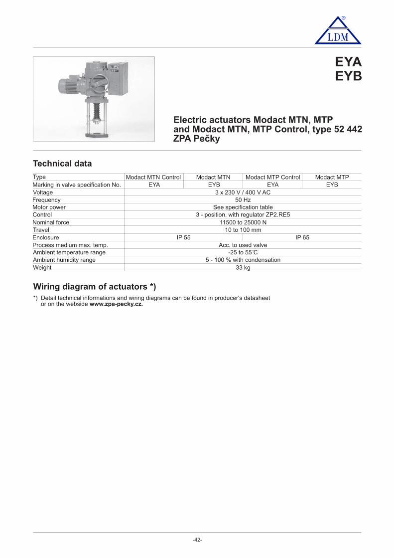
®
EYAEYB
-4 -2
Electric actuators Modact MTN, MTPand Modact MTN, MTP Control, type 52 442ZPA Pečky
Technical data
Marking in valve specification No.VoltageFrequencyMotor powerControlNominal forceTravelEnclosureProcess medium max. temp.Ambient temperature rangeAmbient humidity rangeWeight
3 x 230 V / 400 V AC50 Hz
See specification table3 - position, with regulator ZP2.RE5
11500 to 25000 N10 to 100 mm
Acc. to used valve-25 to 55 C
5 - 100 % with condensation33 kg
Wiring diagram of actuators *)
Type
o
EYAModact MTN Control
EYAModact MTP Control
EYBModact MTN
EYBModact MTP
IP 55 IP 65
*) Detail technical informations and wiring diagrams can be found in producer's datasheetor on the webside www.zpa-pecky.cz.

®
-43-
Specification of actuators Modact MTN, MTP and Modact MTN, MTP Control
Basic equipment 2 power switches MO, MZ2 limit switches PO, PZ2 limit and signalisation switches SO, SZ
1 position transmitter - resist. 2x100 or current2 limit switches PO, PZ2 limit and signalisation switches SO, SZ
Basic technical parameters
TypePower switchsetting range
kN
Directpower kN
Resettingspeed
mm.min
Travelmm Aluminium Basic Additional
Weight Specification No.
XX0XXMXX1XXM
33 XX3XXMXX2XXMXXAXXM
52 442XX4XXMXX5XXM
33 XX6XXMXX7XXMXX8XXM
11,5 - 15
15 - 25
17
32,5
5080
12536275080
1253627
10 - 100
10 - 100
Execution, electric connectionVia terminal boardWith conector HARTING
6XXXXM7XXXXM
Position transmitter
Current transmitterDCPT with source
Current transmitterCPT without sourceAdditional electric equipment
Modact Controlexecution
(with built-incontactor
combination)
Without brake BAM and positionerWith brake BAM, without positionerWith brake BAM and with positionerWithout brake BAM and positioner
without BMO
with BMO With brake BAM, without positionerWith brake BAM and with positioner
Notes:When execution with flasher is requested, specify this requirment in writing: Execution with flasher1)
Design without force locking after reversation have at end position capital letter M (for example: 52442.6211NM)2)
For actuators MODACT MTN Control s with position controllers ZP2.RE5 specify number 5 on place 113)
-1
MTN 15MTP 15
MTN 25MTP 25
PowerW rpm
1/minIn (400V)
AIzIn
Electromotor MTN
180 850 0.74 2.3180 850 0.74 2.3250 1350 0.77 3.0120 645 0.51 2.2120 645 0.51 2.2180 835 0.74 2.3180 835 0.74 2.3250 1350 0.77 3.0120 645 0.51 2.2120 645 0.51 2.2
rpm1/min
In (400V)A
IzIn
Electromotor MTP
835 0.62 2.3835 0.62 2.3
1350 0.76 3.0645 0.51 2.2645 0.51 2.2835 0.62 2.3835 0.62 2.31350 0.76 3.0645 0.51 2.2645 0.51 2.2
Execution Modact MTN; Modact MTN Control ... enclosure IP55Execution Modact MTP; Modact MTP Control ... enclosure IP67
XXXXNMXXXXPM
Current transmitterDCPT with source
Current transmitterCPT without source
XXXR MXXXXS MX
XXX0 MXXXX1 MXXXX2 MXXXX3 MXXXXP MXXXXZ MX
current 4 - 20 mAcurrent 4 - 20 mA with BMOresistance transmitter 2x 100 resistance transmitter 2x 100 s BMOwithout transmitter, with BMOwithout transmitter, without BMO
Resistance transmitter2x 100 ohm
XXXAXMXXXBXM
XXXCX5M 3)
XXXDXMXXXEXM
XXXFX5M 3)
XXX4XMXXX5XM
XXX7XMXXX8XM
XXXKXMXXXLXM
XXXMXMXXXNXM
[kg]2)
1)
Connection dimensions - details of additional specification No. 52 442BbgIIIIII
15074
130M 20x1,5M 16x1,5M 10x1
Pitch of columns
Position"closed"
Clutch thread
Specification No.basic
52 44252 44252 44252 442
additionalXLXXXMXMXXXMXPXXXMXRXXXM
Execution
Bb2IBb2IIBb2IIIBg2I
position
closed
For valves
---RV 2xx DN 80 to 150RV 2xx DN 15 to 65RV 2xx DN 200 to 400

Dimensions of actuatorModact MTN, MTP
Dimensions of actuator Modact MTN,MTP and Modact MTN, MTP Control
®
-44-
- with terminal board - with conector
∅ CABLE 9 - 16 mmMAX. 595
MAX. 334 261
32
5
e(a
)
c(a)
d(b
), h
(g)
25
3
10
0(1
53
)a,b
,g
M20 ∅26
f(b),
ch(g
)
25
215
99
90
4x P16
EXTERNAL PROTECTINGCLAMP
MÍSTNÍ OVLÁDÁNÍ
1x CABLE GLAND M25x1,5
AB
EXECUTION 2
1x CABLE GLANDrozsah ∅13 - 18 mm
2x CABLE GLANDrange ∅∅10 - 14 mm
1x CABLE GLANDrange ∅6 - 12 mm
EXTERNAL PROTECTINGCLAMP
Execution 2A 160B 150a 30b 74g 130
c (a) 308d (b) 352h (g) 408e (a) 605f (b) 649
ch (g) 705
Provedení 2A 160B 150a 30b 74g 130
c (a) 308d (b) 352h (g) 408e (a) 633f (b) 677
ch (g) 733
Execution 2A 160B 150a 30b 74g 130
c (a) 308d (b) 352h (g) 408e (a) 633f (b) 677
ch (g) 733
Dimensions of actuator Modact MTN, MTP Control
- with terminal board
Detail of coupling
- ONLY AFTER AGREEMENT WITH PRODUCER
1x CABLE GLAND 25x1,5CABLE
LOCAL CONTROL
1x CABLE GLAND 25x1,5CABLE
M25x1,5CABLE
M25x1,5CABLE
EXTERNAL PROTECTINGCLAMP
LOCAL CONTROL
EXECUTION 2EXECUTION 2
LOCAL CONTROL

®
EYA
-4 -5
Electric actuators Modact MTNEDand Modact MTPED, typ 52 442ZPA Pečky
Technical data
Marking in valve specification No.
VoltageFrequencyMotor powerControlNominal forceTravelEnclosureProcess medium max. temp.Ambient temperature rangeAmbient humidity rangeWeight
3 x 230 V / 400 V AC50 Hz
See specification table3 - position, or continuous
11500 to 25000 N10 to 100 mm
Acc. to used valve-25 to 55 C
5 - 100 % with condensation33 kg
Wiring diagram of actuators *)
Type
o
IP 55 IP 65
*) Detail technical informations and wiring diagrams can be found in producer's datasheetor on the webside www.zpa-pecky.cz.
EYAModact MTNED Modact MTPED
Execution The actuator equiped with electronic system DMS2 or DMS2 ED
Elektric equipment
System DMS2 EDThe more simple system DMS2 ED substitutes electromechanical parts and/or provides for controlling the electricactuator by input analog signal as in the version Control.
Torque-limit unit
Optional equipmentF signaleedbackAnalog regulatorPosition IndicatorRelay controlor contactless control unitElectronic brake
Control unit
Source unit
It also contains the sensor of position of the output shaft, 4 push-buttonsand 3 signal LEDs for setting and checking the actuator.
Contacts of seven relays (MO, MZ, PO, PZ, SO, SZ, READY) are connected tothe terminal board; state of each relay is signalized by LED. The unit enables theheating resistor to be connected and controlled by the thermostat.
4-20 mA
LED display
Basic equipment

®
-46-
System DMS2The system DMS2 enables the electric actuator to be used for two-position and three-position regulation or to beconnected to the industrial bus bar Profibus.
Torque-limit unit
Recommended equipmentElectronic brakeOptional equipment (t )he electric actuator must be fitted with one of these units
Unit of two- and three-positioncontrolUnit of connection Profibus
Note: T .he electronic control DMS2 checks, within its function, sequence and fall-out of phases of supply voltage
Control unit
Source unit
It also includes a sensor of the output shaft position2 signal LED
- 2 relays for electric motor control- Relay with change-over contact connected to the terminal boardReady
- Signalling relays 1 - 4 with one pole of the switching contact connected to the terminal board
After switching-off the motor reduces running down and precises the control
Control of the electric actuator by shifting to position Open and Close
Basic equipment
Second poles of the switching contacts of relays 1 - 4 are interconnected
Heating resistor switched by a thermostat is connected to the unitThe unit controls power switches of the electric motor (reversing relay)To the unit can be connected an electronic brake
Unit of displayUnit of push-buttons
Two-row display, 2 x 12 alpha-numeric charactersPush-buttons Selector switch"Open", "Close", "Stop"; "Local", "Remote", "Stop"
or by analog signal 0(4) - 20 mAControl of the electric actuator by industrial bus bar Profibus
Specification of actuators Modact MTNED a MTPED
Basic technical parameters
TypePower switchsetting range
kN
Directpower kN
Resettingspeed
mm.min
Travelmm Basic Additional
Weight Specification No.
33
52 442
33
11,5 - 15
15 - 25
17
32,5
5080
12536275080
1253627
10 - 100
10 - 100
Execution Modact MTNED ... enclosure IP55Execution Modact MTPED ... enclosure IP67
-1
MTNED 15
MTPED 15
MTNED 25
MTPED 25
PowerW rpm
1/minIn (400V)
AIzIn
Electric motor MTN
180 850 0.74 2.3180 850 0.74 2.3250 1350 0.77 3.0120 645 0.51 2.2120 645 0.51 2.2180 835 0.74 2.3180 835 0.74 2.3250 1350 0.77 3.0120 645 0.51 2.2120 645 0.51 2.2
rpm1/min
In (400V)A
IzIn
Electric motor MTP
835 0.62 2.3835 0.62 2.3
1350 0.76 3.0645 0.51 2.2645 0.51 2.2835 0.62 2.3835 0.62 2.31350 0.76 3.0645 0.51 2.2645 0.51 2.2
Execution, circuity, electronic equipment
DMS2, ED electronicsDMS2, Profibus electronicsDMS2, 2-position or 3-position control *)
KXXXXEDYXX0XED
HXXXXEDUXX0XEDWXX0XED
FXXXXEDTXX0XEDVXX0XED
EXXXXEDPXX0XEDRXX0XED
brakeConectorTerminal boardTerminal board,
brakeConector,
*) Producer will set in production 2- or 3- position control. If not specified in the order,
Equipment Character at the 9. position (52 442 xxxXxED)0 1 2 3 4 5 6 7 8 9 A B C D E F H J K L M N P R
x xxx
x x
xxx
xx
x
x x
xx
x x
xx
xx
xx
x
xx
x xx
x
x xx
xx
x
x
x xx
xx
xxx
xxx
x
xxx
xxxx
xx
Equipment of DMS2ED electronics
Local controlDisplayRelay
Analog module TransmitterRegulator
Note: In the case of using an electronic DMS2 is the character at the 9. position 0
Aluminium[kg]
XXX0XED
and brought out to the terminal COM
the gearmotor is set to 3-position control (signal control 4-20 mA).
XX0XXEDXX1XXEDXX3XXEDXX2XXEDXXAXXEDXX4XXEDXX5XXEDXX6XXEDXX7XXEDXX8XXEDXXXXNEDXXXXPED

®
-47-
Dimensions of actuator Modact MTNED/MTPED
- with conector - with terminal board
Execution 2A 160B 150a 30b 74g 130
c (a) 308d (b) 352h (g) 408e (a) 605f (b) 649
ch (g) 705
Execution 2A 160B 150a 30b 74g 130
c (a) 308d (b) 352h (g) 408e (a) 633f (b) 607
ch (g) 763
Connection dimensions - details of additional specification No. 52 442
BbgIIIIII
15074
130M 20x1,5M 16x1,5M 10x1
Pitch of columns
Position"closed"
Clutch thread
Specification No.basic
52 44252 44252 44252 442
additionalXLXXXMXMXXXMXPXXXMXRXXXM
Execution
Bb2IBb2IIBb2IIIBg2I
position
closed
For valves
---RV 2xx DN 80 to 150RV 2xx DN 15 to 65RV 2xx DN 200 to 400
1x CABLE GLAND 25x1,5CABLE
EXTERNAL PROTECTING CLAMP
LOCAL CONTROL
CABLE
CABLE
EXECUTION 2
EXTERNAL PROTECTING CLAMP
LOCAL CONTROL
1x CABLE GLAND 25x1,5CABLE
EXECUTION 2
Detail of coupling
- ONLY AFTER AGREEMENT WITH PRODUCER

®
- -48
Electric actuatorsSA 07.1, SA ExC 07.1, SAR 07.1, SAR ExC 07.1SA 07.5, SA ExC 07.5, SAR 07.5, SAR ExC 07.5Auma
Specification of Auma actuators
TypeSA XXX 07.X
ControlDuty
R
Actuator´ s size
ExC07.1
X
ON - OFFStandard
SA
ExecutionNon-explosive
Technical data
Marking in valve specification No.VoltageFrequencyMotor powerControlNominal forceTravelEnclosureProcess medium max. temperat.Ambient temperature rangeAmbient humidity limitWeight
380 or 400 V AC50 Hz
See specification table3 - position control or with signal 4 - 20 mA
Acc. to used valve
100 %
Type
IP 67
20 kg
EAA, EAB, EAC, EADEAE, EAF, EAG, EAH
EADSAR ExC 07.1
EAASA 07.1
EABSA ExC 07.1
EACSAR 07.1
EAHSAR ExC 07.5
EAESA 07.5
EAFSA ExC 07.5
EAGSAR 07.5
30 Nm 15 kN; 40 Nm 20 kN~ ~acc to valve stroke 16, 25, 40 mm
10 Nm 5 kN; 15 Nm 7,5 kN; 20 Nm 10 kN~ ~ ~acc to valve stroke 80, 100 mm
07.5
4
Out
put s
peed
(rp
m)
Trip
ping
torg
ue5,681116223245
SA 07.1 SA ExC 07.1 SAR 07.1 SAR ExC 07.1SA 07.1 SAR 07.1
SAExC07.1 SARExC07.1
Mot
or p
ower
[ kW
]
10-30Nm
15-30Nm
0,0250,0250,0450,0450,090,090,180,18
0,0250,0250,0450,0450,090,090,180,18
Output shaft type A thread connection flange( TR 16x4 LH, F07) ... for RV 2xx DN 15 to 150
0,0250,0250,0450,0450,090,090,180,18
0,0250,0250,0450,0450,090,090,180,18
4
Out
put s
peed
(rp
m)
Trip
ping
torg
ue5,681116223245
SA 07.5 SA ExC 07.5 SAR 07.5 SAR ExC 07.5SA 07.5 SAR 07.5
SAExC07.5 SARExC07.5
Mot
or p
ower
[ kW
]
20-60Nm
30-60Nm
0,0450,0450,090,090,180,180,370,37
Output shaft type A thread connection flange( TR 20x4 LH, F10) ... for RV 2xx DN 80 to 400
0,0450,0450,090,090,180,180,370,37
0,0450,0450,090,090,180,180,370,37
0,0450,0450,090,090,180,180,370,37
-25 to 80 C -20 to 40 C -25 to 60 C -20 to 40 Co o o o
-25 to 80 C -20 to 40 C -25 to 60 C -20 to 40 Co o o o

®
Other accessories acc. to catalogue of producer of actuators.
Accessories2 TANDEM switchesGearing for signalisation of positionMechanical position indicatorPotentiometer 1x200 Electronic position transmitter RWG (potentiometer included), 4 - 20 mA, 2-wireElectronic position transmitter RWG (potentiometer included), 4 - 20 mA, 3/4-wireInductive position transmitter IWG, 4 - 20 mAMATIC - , weight + 7 kgor continuous control (specification of accessories acc. to catalogue of producer)AUMATIC - , weight + 7kgor continuous control (specification of accessories acc. to catalogue of producer)
-49-
Dimension of Auma actuators 07.1 and 07.5Standard execution ExC execution
16
0
63
16
0
Output drive type A
Attachment yoke (2 or 4 columns)
Version with MATIC / AUMATIC
16
0
110 272
A B
2
Numberof columns
140 4204
For valves
RV 2xx DN 15 to 150RV 2xx DN 200 400to
~ 8 kg
Weight
~ 15 kg
186
24
4
21
0
A
B
25
4
63186
186 63
34
0 /
30
0

®
-5 -0
Electric actuatorsSA 10.1, SA ExC 10.1SAR 10.1, SAR ExC 10.1Auma
Specification of Auma actuators
TypeSA XXX 10.1
ControlDuty
R
Actuator s size’ExC
10.1
X
ON - OFFStandard
SA
ExecutionNon-explosive
Technical data
Marking in valve specification No.VoltageFrequencyMotor powerControlNominal forceTravelEnclosureProcess medium max. temperat.Ambient temperature rangeAmbient humidity limitWeight
380 or 400 V50 Hz
See specification table3 - position control or with signal 4 - 20 mA
Acc. to used valve
100 %
Type
IP 67
-25 to 80 C
2 kg4 to 27
o -2 to 40 C0 o -25 to 60 Co -2 to 40 C0 o
4
Out
put s
peed
(rp
m)
Trip
ping
torg
ue5,681116223245
Mot
or p
ower
[ kW
]
40-120Nm
60-120Nm
Output shaft type A thread connection flange( TR 36x4 LH, F10) ... for RV 2x4 DN 200 to 600
EAI, EAJEAK, EAL
EAKSAR ExC 10.1
EAISA 10.1
EALSA ExC 10.1
EAJSAR 10.1
80 Nm 21,6 kN; 100 Nm 27 kN; 120 Nm 32 kN~ ~ ~Acc. to used valve 80, 100 mm
SA 10.1 SA ExC 10.1 SAR 10.1 SAR ExC 10.1
0,090,090,180,180,370,370,750,75
0,090,090,180,180,370,370,750,75
0,090,090,180,180,370,370,750,75
0,090,090,180,180,370,370,750,75
SA 10.1 SAR 10.1
SAExC10.1 SARExC10.1

®
Other accessories acc. to catalogue of producer of actuators.
Accessories2 TANDEM switchesGearing for signalisation of positionMechanical position indicatorPotentiometer 1x200 Electronic position transmitter RWG (potentiometer included), 4 - 20 mA, 2-wireElectronic position transmitter RWG (potentiometer included), 4 - 20 mA, 3/4-wireInductive position transmitter IWG, 4 - 20 mAAUMATIC - for continuous control (specification of accessories acc. to catalogue of producer)
-51-
Dimension of Auma actuators 10.1
Output drive type A, F 10
Attachment yoke DN 200 - 400Output drive type A, F10, Tr36x6-LH
Standard execution ExC execution
80
254
191 63282
80
200
191 63282
191 63282
65
50
254
200
4050
4xM10
22
70
102125
65
2475
0
200
340 / 3
00
80
247
42
47
Attachment yoke DN 600Output drive type A, F10, Tr36x6-LH
210
65
Version with MATIC / AUMATIC
200
340 / 3
00
80

®
Electric actuators ...AB3, ...AB5Schiebel
EZA, EZBEZC, EZD
EZG, EZHEZE, EZF
-52-
Technical data
Mark in valve´s spec. No.Voltage ACFrequencyMotor powerControlNominal forceStrokeEnclosureProcess medium max. t.Ambient temp. rangeAmbient humidity limitWeight
EZD400 / 230 V; 230 V
50 HzSee specification table
3 - position control of continuous 4 - 20 mA80 Nm 32 kN~
Acc. to the valve stroke 16, 25, 40, 80, 100 mmIP 66
Acc. to used valve-25 to 80 C
90 % (tropical version: 100 % with condensation)
Specification of actuators
16 kg
Type exrAB3EZAAB3
EZBexAB3
EZCrAB3
400 / 230 V; 230 V400 / 230 V 400 / 230 V
IP 65 IP 66 IP 65
-20 to 40 C -25 to 80 C -20 to 40 C
Non-explosiveX AB3 X + XXX
Standard
DutyR
AB5A
AXX
Execution
ControlON - OFF
Ex
400/230V
2,5
Out
put s
peed
(rp
m)
Trip
ping
torg
ue
57,51015203040
FFFESM21CMR
230V 400/230V 230V
AB5 rAB5 exAB5 exrAB5AB5 rAB5exAB5 exrAB5
2,55
7,51015203040
Mot
or p
ower
[ kW
]
Accessories
Potentiometer 1x1000 Double potentiometerElectronic transmitter 4 - 20 mAPositioner ACTUMATIC R
10-60Nm
400/230V400/230V
0,090,120,090,180,180,370,370,37
0,090,120,090,180,180,370,370,37
0,090,120,090,120,180,180,370,37
0,090,120,090,120,180,180,370,37
0,090,120,120,250,250,550,751,10
0,090,120,090,120,180,180,370,37
12 kg 16 - 18 kg 16 kg
o o o o
EZHexrAB5
EZEAB5
EZFexAB5
EZGrAB5
AB3Actuator´s torque
400/230V
2,5
Out
put s
peed
(rp
m)
Trip
ping
torg
ue57,51015203040
230V 400/230V 230V
AB3 rAB3 exAB3 exrAB3AB3 rAB3exAB3 exrAB3
2,55
7,51015203040
Mot
or p
ower
[ kW
]
10-30Nm
400/230V400/230V
0,090,120,090,090,090,090,180,18
0,090,120,090,090,090,090,370,37
0,090,120,090,090,180,370,250,25
0,090,030,090,090,090,090,250,25
0,090,120,090,090,090,180,250,25
0,090,030,090,090,090,090,550,55
Output shaft type A (thread TR 16x4 LH, connection flange F07 )... for RV 2x4 DN 200 to 400
Tripping7 - 30Nm
Loading7 - 15Nm
Tripping30 - 60
Nm
Loading15 - 30
Nm
CSCSMARTCON control unit

®
- -53
Dimension of actuators ...AB3, ...AB5
Output drive type A Attachment yokeOutput drive type A
110 272
A B
2
Numberof columns
140 4204
For valves
RV 2xx DN 15 až 150RV 2xx DN 200 až 400
~ 8 kg
Weight
~ 15 kg

®
Electric actuators ...AB8Schiebel
Technical data
Marking in valve´s specification No.
Voltage ACFrequencyMotor powerControlNominal force
StrokeEnclosureProcess medium max. temp.Ambient temperature rangeAmbient temperature limitWeight
50 HzSee specification table
3 - position or with signal of 4 - 20 mA(Tr 20x4 LH) 30 Nm 15 kN; 40 Nm 20 kN� �
25 mm
Acc. to used valve
90 % (tropical version 100 % with condensation)
Specification of actuator
Type
400 / 230 V; 230 V
X AB8 X + XXXNon-explosive
Duty r
Output shaft type (connection flange size F10, thread x20 4... for to 6RV 2xx DN 250 00)
AB8
A
AXXExecution
Control
2,5
Out
put s
peed
}rp
m]
Trip
ping
torq
ue57,51015203040
FFFESM21CMR
rAB8
2,55
7,51015203040
Mot
or p
ower
[ kW
]
Accessories
Potentiometer 1x1000 Double potentiometerElectronic transmitter 4 - 20 mAPositioner ACTUMATIC R
30-80Nm
IP 66
-25 to 80 Co
24 kg
EZKrAB8
Actuator size
EZKEZL
IP 65
-2 to 0 C0 4 o
2 kg0
EZLexrAB8
400 / 230 V; 230 V
Normalex
rAB8230V0,120,120,180,370,370,751,101,10
400/230V0,120,120,180,370,370,550,751,10
exrAB8400/230V
0,120,120,180,180,370,370,751,10
- -54
*) for switching torques exceeding 40 Nm the thread TR 36x6 LH, flange F10 is applied
CSCSMARTCON control unit
(Tr 36x6 LH) 80 Nm 21,6 kN; 100 Nm 27 kN; 120 Nm 32 kN� � �

®
- -55
Output shaft type A, flange F10
Dimensions of actuators ...A 8B
Attachment yoke DN 200 - 400Output drive type A, F10, Tr36x6-LH
Attachment yoke DN 600Output drive type A, F10, Tr36x6-LH

®
- -56
EDA, EDB, EDCEDD, EDI, EDK
Electric actuators D, DR, DMI, DMI REMG - Drehmo
Technical data
Mark in valve´s spec. No.VoltageFrequencyMotor powerControlNominal forceStrokeEnclosureProcess medium max.t.Ambient temp. rangeAmbient humidity limitWeight
EDA EDB EDIEDC EDD EDK380 / 400 V; 230 V AC
50 HzSee specification table
3 - position control or continuous 4 - 20 mA15 Nm ~ 7,5 kN; 20 Nm ~ 10 kN; 30 Nm ~ 15 kN
Acc. to the valve stroke: 16, 25, 40, 63 mmIP 67
Acc. to used valve-25 to 80 C -25 to 70 C -25 to 40 C
100 % with condensation18 kg 18 kg 18 kg28 kg 28 kg 28 kg
Type D30 DR30 DR30ExDMI30 DMIR30 DMIR30Ex
o o o
Accessories1. Torque switches in closing and opening direction DR11/DL21
3. Electronic transmitter, feeding 24 V; feedback 0/4 - 20 mA2. Resistance sensor 22 , B1
4. Mechanical position indicator5. Position signalisation drive (necessary for item No. 2 and 4)
Specification of actuators EMG - Drehmo
TypeXXX A
A
X XXXXX
Drehmo MaticDrehmo Standard
Duty
Execution
DMI
XX
Control
Normal
D
R
Out
put s
peed
(rp
m)
Trip
ping
torq
ue
5 510 1016 16
50 50
25 25
80 80
32 32
120 120
40 40
160 160
D30... D 30 DMI R 30
DMI30... DR30 DMIR30Ex
Mot
or p
ower
[ kW
]
10-30Nm
0,120,120,12
---
0,12
---
0,34
---
0,25
---
DMI 30DR30...
D R 30 ExDMIR30...
0,120,120,12
0,34
0,12
0,34
0,34
0,34
0,25
0,75
Output shaft type A (thread TR 16x4 LH, connection flange F07; thread TR 20x4 LH, flange F10 )Actuator´s torque 30
ON - OFF
Non-explosive
30 [Nm]
Ex

®
-57-
Dimension of actuators EMG - Drehmo
Attachment yoke
28
max 26
55
70
90
4xM8
20
272
110
Stadartd execution Version with MATIC
250; 352; 452
453
305
250; 352; 452
453
305
Output drive type A, flange F07

®
-58-
EQA, EQB
Elektric actuators ...IQM7Rotork
Technical data
Marking in valve specification No.VoltageFrequencyMotor powerControlTorqueStrokeEnclosureProcess medium max. temperatureAmbient temperature rangeWeight
50 HzSee specification table
0 - 5, 0 - 10, 0 - 20 and 4 - 20 mA; 0 - 5, 0 - 10 and 0 - 20 V15 Nm 7,5 kN; 20 Nm 10 kN; 30 Nm 15 kN� � �
Acc. to valve stroke 16, 25, 40 mm
Acc. to used valve
30 kg
Specification of actuator
TypeEQB
Ex IQM7
400 V AC
IP 68
Non-explosiveIQM7 X + XXX
Standard
Output drive type (thread TR 20x4 LH, connection flange F10) A
AXX
ExecutionEx
Folomatic
CPT
CTTAccessories
Positioner FolomaticPosition transmitter 4 - 20 mAOutput torque transmitter 4 - 20 mA
-20 to 70 Co
EQAIQM7
IQM7Actuator´s size
Out
put
spee
d (r
pm)
Trip
ping
torq
ue
18
IQM7 Ex IQM7IQM7
18
Mot
or p
ower
[ kW
]
13,6-34Nm
0,050,05

®
- -59
Dimensions of actuators ... IQM7
Output drive type A
Dimension marked * - free place for dismantling of actuator’s housing
Actuator ... IQM7
Attachment yoke
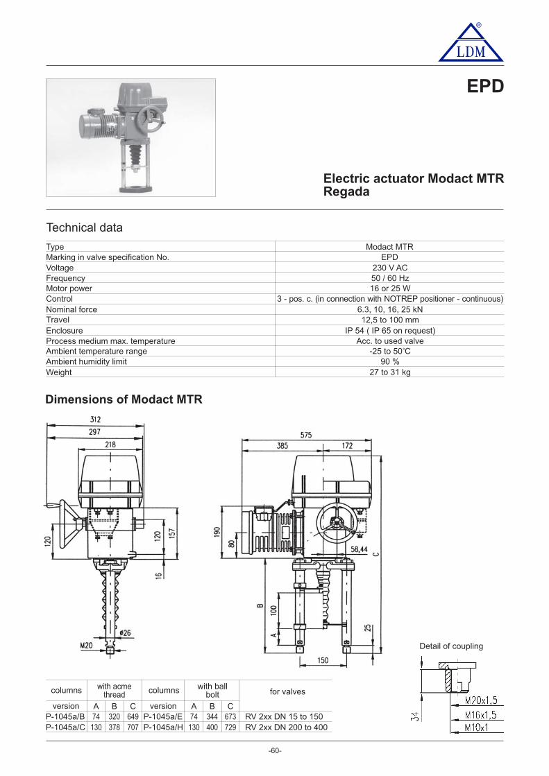
®
- -60
Electric actuator Modact MTRRegada
EPD
Technical data
Marking in valve specification No.VoltageFrequencyMotor powerControlNominal forceTravelEnclosureProcess medium max. temperatureAmbient temperature rangeAmbient humidity limitWeight
EPD230 V AC50 / 60 Hz16 or 25 W
3 - pos. c. (in connection with NOTREP positioner - continuous)6.3, 10, 16, 25 kN12,5 to 100 mm
IP 54 ( IP 65 on request)Acc. to used valve
-25 to 50 C90 %
27 to 31 kg
Type Modact MTR
o
Detail of coupling
Dimensions of Modact MTR
P-1045a/B
with acmethread
with ballbolt
74 320 649 74 344 673
A B C A B C
columns
P-1045a/E
columns
versionversion
P-1045a/C 130 378 707 130 400 729P-1045a/H
for valves
RV 2xx DN 15 to 150RV 2xx DN 200 400to

®
- -61
Specification of Modact MTR
Electric actuator MTR, linear 52 420. X X X X / X XMild up to hot dry with temperature range (-25 C to +50 C)o o 0
XX -
Electric conectionTo terminal boardTo connector
Voltage Wiring diagram
230 V AC Z29698
Electric motorPower Speed Current
0.31 A
0.41 A
0.31 A
1 150
1 250
1 150
16 W
25 W
16 W
0.41 A1 25025 W
ABCDEF
HJK
Control board version Wiring diagram
Electromechanical control board -without local control
16 mm25 mm
Operating stroke
BC
40 mm EZ298
4 000/5010 000/32
16 000/32-G10 000/ -G50
16 000/50-G10 000/63-G6 300/100-G
6 300/50
4.0 - 6.3 kN
6.3 - 10.0 kN
10.0 - 16.0 kN6.3 - 10.0 kN
10.0 - 16.0 kN6.3 - 10.0 kN4.0 - 6.3 kN
4.0 - 6.3 kN
Rated opera-ting speed
OperatingspeedScrew version Switching-off
thrust 1) 2)
6 300/322.4 - 4.0 kN
trap
ezoi
dal
thre
adba
llsc
rew
32 mm/min.
32 mm/min.
32 mm/min.50 mm/min.
50 mm/min.63 mm/min.
100 mm/min.
50 mm/min.
50 mm/min.38 - 32 mm/min.
38 - 32 mm/min.
38 - 32 mm/min.60 - 50 mm/min.
60 - 50 mm/min.75 - 63 mm/min.
120 - 100 mm/min.
60 - 50 mm/min.
60 - 50 mm/min.
SingleDouble
DoubleWithout power supply
Single
Connection OutputTransmitter
Without transmitter
Resistive
Resistive withcurrent converter
CapacitiveCPT
Without power supply
Without power supply
With power supply
With power supply
Without power supplyWith power supply
With power supply
Wiring diagram
— — — A
—
2-wire
3-wire
2-wireWith power supply
Without power supply
1x100 2x100
1x2000 2x2000
4 - 20 mA
0 - 20 mA
4 - 20 mA
0 - 5 mA
4 - 20 mA
Z5aZ6aZ5aZ6a
Z10aZ269aZ257aZ260aZ257aZ260aZ257aZ260aZ10a
Z269a
BCFPSQTU
WV
YZIJ
Dimensionaldrawing
150/ —C130/100
Pillar spacing /Bore of flange
Thread ofstem 3)
Mechanicalconnection
Connectinghight / stroke
M20x1.5M16x1.5, M10x1
ColumnsP-1045a/B; P-1045a/E74/100
Additional equipment Wiring diagram
AB
Without additional equipment; adjusted max. switching-off thrust from range2 additional position switches S5,S6Adjustment of switching-off thrust for required value
00
0 123
1) State the switching-off thrust in your order by words. If not stated it is adjusted to the maximum rate of the correspondingrange. The load torgue equals minimally the maximum switching-off thrust of the choosing range multiplied by 1.3.
2) The maximum load thrust equals the max. Switching-off thrust multiplied by:- 0.8 for duty cycle S2-10 min., r S4-25%, 6 - 90 cycles per houro- 0.6 for duty cycle S4-25%, 90 - 1200 cycles per hour
3) The thread in the coupling is to be specified in the order by words.
Notes:
Z298
Possible combinations and execution: A+B = 07
25 000/32-G 10 0 25. - .0 kN 32 mm/min. 38 32- mm/min. G
63 mm80 mm
100 mm
FGH
BP-1045a/ ; P-1045a/C H

®
- -62
Legend:Z5a connection of single resistive transmitterZ6a connection of double resistive transmitterZ10a connection of resistive with current converter of capacitive transmitter - 2-wire without supplyZ257b connection of resistive transmitter with current converter - 3-wireZ260a connection of resistive transmitter with current converter - 3-wire with power supplyZ269a connection of resistive transmitter with current converter or capacitive transmitter - 3-wire with power supplyZ296 conection of 1-phase electric motorZ298 conection of thrust and position switches and space heater
B1 resistive trasmitter (potentiometer) singleB2 resistive trasmitter (potentiometer) doubleB3 capacitive transmitterS1 thrust switch "open"S2 thrust switch "closing"S3 position switch "open"S4 position switch "closed"S5 additional position swich "open"S6 additional position "closed”M motorC capacitorY motor’s brakeE1 space heaterX terminal boardX3 electric motor’s terminal boardI/U input (output) current (voltage) signalsR reducting resistorR loading resistorL
Wiring diagram of actuator Modact MTR
Notes:1. For the EA version with connection to the terminal board, the terminal 1/60
(the wiring diagrams Z269a and Z260a) is leaded out to the terminal No. 1.2. For EA version with connection to the terminal board the actuator is not
equipped by the jumper X3:6-X:7 and X3:2-X:8 (Z296) from manufacturingplant (it is necessary to connect it by customer).

®
- -63
Electric actuatorsST 0Regada
EPK
Technical data
EPK
50 / 60 Hz1 W
3 - position (0 - 10 V, (0)4 - 20 mA)2,9 kN and 4,5 kN
16, 25 mmIP 54
acc. to used valve-25 to 55 C
5 - 100% with condensation
Dimensions of actuators
2,5 to 4,5 kg
ST 0
230 V AC, 24 V AC
o
Marking in valve specification No.VoltageFrequencyMotor powerControlNominal forceTravelEnclosureProces medium max. temperatureAmbient temperature rangeAmbient humidity rangeWeight
Type
P-1182/A
Execution
110 25 275 55 85
L Z M A B
1)applies to actuators ES ST 0 with converterand to ES ST 0 with positioner
M10x1
Dimensions of coupling

®
-64-
Specification of actuator ST 0
Electric actuator Isomact ST 0 490. X X X X / X X
230 V AC24 V AC
16 mm/min2900
Tripping torque
X - X
A
3
S regulátorem 1)
Electric connection 0
2,75 W
Travel
16 mm25 mm
00Accessories
Terminal board Wiring diagramZ20
Voltage
Two-torque
Without transmitter A
Rem
ote
posi
tion
tran
smitt
er
Wiri
ng
Fee
dbac
k
Wiri
ng d
iagr
am
BF
1 x 100 1 x 2000
STVY
Resistance
4 - 20 mA0 - 20 mA4 - 20 mA0 - 5 mA
Z22
2-wire
3-wire
Z23
Z21Mechanical connection - flange, connecting height 110 mm, thread on con. stem M10x1 L
2 auxiliary position switches 2)
Wiring diagram for actuator ST 0
Resistance to surroundings0Normal execution (without positioner)
10 mm/min4500 NRunning speed Motor power
2,75 W5 mm/min4500 A2,75 W4 mm/min2900 0
Nominal force [ N ]
1 W
Single
Electronic- current(without generator)
Z236, Z237Wiring diagram
B1 remote position transmitter - resistance, singleB3 resistance transmitter with converterM, MS single-phase electromotorC capacitorN positionerF1 heat protection of electromotorX, X1, X2 terminal boardY brake of electromotorR loading resistanceR bL allast resistor
-
S1 power switch for “open” positionS2 power switch for “closed” positionS3 position switch for “open” positionS4 position switch for “closed” positionS5 additional limit switch for “open” positionS6 additional limit switch for “closed” positionI(U) input and feedback current (voltage) signals
16 mm25 mm
One-torque
RT
Note: The actuator is not equipped with hand wheel if Regada positioner is used1)
Note:2)
The version with a positioner and with a lead-out transmitter cannot have specified also 2 additional position switches

®
- -65
Electric actuatorsST 0.1Regada
EPL
Technical data
EPL
50 / 60 Hz15W
3 - position control (0 - 10 V, 4 - 20 mA)4,6 a 7,2 kN
16, 25, 40 mmIP 65
Acc. to used valve-25 to 55 C
5 - 100% with condensation
Dimensions of actuators
5,4 to 8 kg
ST 0.1
230 V AC, 24 V AC
o
Marking in valve specification No.VoltageFrequencyMotor powerControlNominal forceTravelEnclosureProces medium max. temperatureAmbient temperature rangeAmbient humidity rangeWeight
Type
for
for

®
-66-
Specification of actuator ST 0.1
Electric actuator Isomact ST 0.1 498. X X X X / X X
230 V AC24 V AC
10 mm/min16 mm/min
4600
Tripping torque
25 mm/min32 mm/min
Without transmitter A
X - X
C
3
G
IJ
DFH
Current feedback
Electric connection0
Nom
inal
forc
e[ N
]
Runnin
gsp
eed
Mot
orpo
wer
15 W
H
Travel16 mm25 mm40 mm
Rem
ote
posi
tion tra
nsm
itter
Wirin
g
Feedback
Wirin
g d
iag
ram
I
JCapacity
Wo. its source
With its source 4 - 20 mA Z45
30C
BFKP
1 x 100 1 x 2000 2 x 100
2 x 2000 SQTU
Resistance
4 - 20 mA
0 - 20 mA
W
Z22
Terminal board Wiring diagramZ33
Voltage
40 mm/min10 mm/min16 mm/min25 mm/min
40 mm/min
TU
K
V
Y
7200
Two-torque
Wo. its source 2 - wire
Z32
Z23
Z257Z260
Z46
Mechanical connection - flange, connecting height 110 mm, thread on con. stem M10x1 or M16x1,5 C
Accessories
Resistance to surroundings- standard AResistance feedback
0Normal execution (without positioner)
With positionerWiring diagram Z242Wiring diagram Z237
32 mm/min W
Single
Double 6)
V4 - 20 mA
Electronic- current
With its source
Wo. its source
With its source
Wo. its source
With its source
2 - wire
Z269
Z257Z260
Z242
0010
AB
Heater without thermal sensor
2 auxiliary position switches2 auxiliary position switches
Wiring diagram Z270, Z90a
Wiring diagram Z21Wiring diagram Z1a, Z78a
3x400 V AC 9
50D Manual ctrl without pernament standby ---
2 - wire6)
3 - wire6)
3 - wire6)
With its source 51)
2 - wire6)
6) Valid for the version without any possitioner51)
Notes:
For a version with with current feedback only. The output signal fromthe capacitive transmitter is not galvanically insulated from the input signal

®
-67-
Wiring diagram for actuator Isomact ST 0.1
B1 remote position transmitter - resistance, singleB2 remote position transmitter - resistance, doubleB3 resistance transmitter with converterS1 power switch for “open” positionS2 power switch for “closed” positionS3 position switch for “open” positionS4 position switch for “closed” positionS5 additional limit switch for “open” positionS6 additional limit switch for “closed” positionM1 single-phase electromotorC capacitorE1 heaterF1 heat protection of electromotorF2 thermostatic switch of heaterX, X1, X2 terminal boardN positionerI(U) input and feedback current (voltage) signalsR loading resistanceR bL allast resistor

®
-68-
EPJ
Electric actuatorsIsomact ST 1-ExRegada
Technical data
Marking in valve specification No.VoltageFrequencyMotor powerControlNominal forceTravelEnclosureProces medium max. temperatureAmbient temperature rangeAmbient humidity rangeWeight
EPJ
50 / 60 Hz15 W
3 - position control, with positioner 0 - 10 V; (0) 4 - 20 mA7,5 kN
16, 25, 40 mmIP 54
Acc. to used valve-25 to 55 C
5 - 100 % with condensation
Dimensions of actuators
15 kg
Type ST 1-Ex
230 V
Columns
A H L Connection flange type110 50 576 D
o
Type D

®
-69-
Specification of actuator Isomact ST 1-Ex
Maximal stroke (without transmitter) acc. to mechanicalconnection [mm]. Stroke can be adjusted in range from0 to max. stroke value in actuators without transmitter
Without transmitter
Electric connection
Nom
inal
forc
e [ N
]R
em
ote
posi
tion tra
nsm
itter
Mechanical connection - flange, connecting height 110 mm, thread on con. stem M10x1 or M16x1,5
Electric actuator Isomact ST 1-Ex
Schéma zapojení pohonů
Resistance
Resistanceto surroundings-standard
Electronic- current
Capacity
6) Platí jen v provedení bez regulátoru51)
Notes:
Jen provedení s regulátorem s proudouvou zpětnou vazbouV tomto provedení není výstupní signál galvanicky oddělený od vstupního signáluPlatí jen pro provedení bez přídavných polohových spínačů S5, S6 pro 24 V AC56)
411. X - X X X X X
230 V AC
8 mm/min16 mm/min
7500 N10 mm/min20 mm/min
A
J
K
0
56
DFH
0VoltageTerminal board
Runnin
gsp
eed
Mot
orpo
wer
15 W
1
50
Pra
covn
ízd
vih
16 mm25 mm40 mm
Wirin
g
4 - 20 mA
Feedback
CWiring diagram Z248
B1 resistancetransmitter 1x100
B3 position transmitterM1 single-phase
electromotorC capacitorN positionerE1 heaterF1 heat protection of
electromotorF2 thermostastic switch
of heaterX terminal boardR resistanceS1 power switch for
“open” positionS2 power switch for
“closed”positionS3 position switch for
“open” positionS4 position switch for
“closed” positionS5 limit switch for “open”
positionS6 limit switch for
“closed” position
F1 x 100
1 x 2000
S4 - 20 mA
B
T
Jednoduchý
0 - 20 mA
I4 - 20 mA
P-1768
0AWiring diagram Z249
Normal execution (without positioner)
With positionerResistance feedback transmitterResistance feedback transmitter
Wirin
g d
iag
ram
P-1766
VW
4 - 20 mA
U
74080 006Z248
74080700
Z258
74080700
Z258Z261
Z261
Se zdrojemSe zdrojem 51)
Bez zdroje
Bez zdroje
Bez zdroje
Bez zdrojeSe zdrojem
Se zdrojem
2 - vodič
2 -vodič
3 - vodič 6)
2 - vodič 6)
3 - vodič 6)
24 V AC 39400 V AC 6)
232 mm/min
10000 N
740 mm/min
10000 N8600 N5800 N
KP
Dvojitý 6) 56) Z6a
QZ336
2 x 100 2 x 2000

®
-70-
Electric actuatorsST 2, STR 2Regada
EPM
Technical data
EPM
50 / 60 Hzsee specification table
3 - position control with positioner 0 - 10 V, (0) 4 - 20 mA16 a 25 kN40 a 80 mm
IP 65Acc. to used valve
-25 to 55 C5 - 100% with condensation
Dimensions of actuators
17 to 21 kg
ST 2, STR 2
230 V AC, 3x400 V AC
o
RV 2xx DN 80 to 150 (Connection D) RV 2xx DN 200 to 300 (Connection M)
Marking in valve specification No.VoltageFrequencyMotor powerControlNominal forceTravelEnclosureProces medium max. temperatureAmbient temperature rangeAmbient humidity rangeWeight
Type

Specification of actuator ST 2
Electric actuator Isomact ST 2 492. X X X X / X X
19 000 - 25 00012 000 - 16 00019 000 - 25 00012 000 - 16 000
Without transmitter A
X - X
C
A
BL
HJK
Nom
inal f
orc
e [ N
]
Runnin
g s
peed
Mot
or p
ower
20 WJ
Operating stroke40 mm64 mm80 mm
Rem
ote
posi
tion tra
nsm
itter
Wirin
g
Feedback
Wirin
g d
iag
ram
I
JCapacity
Wo. its source
With its source 4 - 20 mA Z269a
91F
BFKP
1 x 100 1 x 2000 2 x 100
2 x 2000 SQTU
Resistance
4 - 20 mA
0 - 20 mA
Z
Z5a
19 000 - 25 00012 000 - 16 000
---12 000 - 16 000
RD
C
V
Z
Wo. its source2-wire
Z6a
Z10a
Z257aZ260a
Z10a
columns, 126 mm, M20x1,5connecting height thread on con. Stem M
Accessories
Resistanceto surroundings AResistance feedback
transmitter
0Normal execution (without positioner) ST2
With positionerSTR2
Wir. diag. Z240a (230 V AC)
---Y
Single
Y0 - 5 mA
Electronic- current
With its source
Wo. its source
With its source
Wo. its source
With its source
With its source
Z269a
Z257aZ260a
Z241a
00
51
A
D1-phase electric motor with protection
2 auxiliary position switches
Space heaterZ1a
Z11a, Z12a, Z21a
Z1a, Z78a, Z41a
-71-
®
Wir. diag. Z251a (3x400 V AC)
Wir. diag. Z241a (230 V AC)
Wir. diag. Z250a (3x400 V AC)
3x400 V AC
10 mm/min
20 mm/min
40 mm/min
60 mm/min
100 mm/min
80 mm/min12 000 - 16 000 E
--- W
---
19 000 - 25 00012 000 - 16 000
Nom
inal f
orc
e [ N
]
Mot
or p
ower19 000 - 25 000
12 000 - 16 00019 000 - 25 000
---
12 000 - 16 00012 000 - 16 000
---12 000 - 16 000
60 W90 W
230 V AC
Max. Without transmitter ... 80 mm With transmitter
3) 3)
4)
4)
4)
5) 6)
WV
4 - 20 mAWo. its source
With its source
Z257aZ260a
Double6)
3-wire
3-wire
2-wire
3-wire
6)
6)
6)
6)
2-wire7)
Mechanical connectionDflange, connecting height 110 mm, thread on con. stem M10x1
70C20E
Electric local controlSpace heater with terminal switch
Z270, Z90a, Z232aZ1a, Z78a, Z41a
Wirin
gdia
gra
m
Current feedbacktransmitter
230 V AC
3x400 V AC - bez N 7
Electric connection
5
To cenector6
230 V AC
3x400 V AC - bez N 9
0
Toterminal board
Wirin
g d
iagra
m 3x400 V AC 21) 2)
3x400 V AC 1) 2)
1)
1)
Z1a + Z11a - bez N
Z78a + Z12a - bez N
Z1a + Z11a - bez N
Z78a + Z12a - bez N
Z303 + Z12a - bez N
Z303 + Z12a - bez N
Wirin
g d
iagra
m
Z344 A24 V DC
3Z348b 24 V AC
Z344 24 V DC C
24 V ACZ348b 8
Notes:1) For the EA version with additional position switches a double transmitter cannot be specified; 2) Version with reversecontacts; 3) Switching thrust from the given range is needed to state by words in the order. If not specified it is adjusted to themaximum value from the given range; 4) Not recommended for the version with controller; 5) The version without any tranmittercan have adjusted its stroke from 0 up to maximum stroke (10 mm, 32 mm, 80 mm); 6) Valid for the version without any controller7) For a version with a controller with currently feedback only. The output signal from the capative transmitter is notgalvanically insulated from the input signal
52G Adjustment of switching-off thrust for required valve
4)
4)

Wiring diagram of actuator ST 2
®
-72-

®
-73-
B1 remote position transmitter - resistance, singleB2 remote position transmitter - resistance, doubleB3 resistance transmitter with converterS1 power switch for “open” positionS2 power switch for “closed” positionS3 position switch for “open” positionS4 position switch for “closed” positionS5 additional limit switch for “open” positionS6 additional limit switch for “closed” positionM single-phase electromotorC capacitorY actuator brakeE1 heater
F1 heat protection of electromotorF2 thermostatic switch of heaterX terminal boardN positionerI(U) input and feedback current (voltage) signalsH1 indication of “open” limit positionH2 indication of “closed” limit positionH3 indication of “elctric local control”SA1 rotary switch with key “remote - 0 - electric local” controlSA2 rotary switch with key “opening - stop - closing”R loading resistanceR bL allast resistor
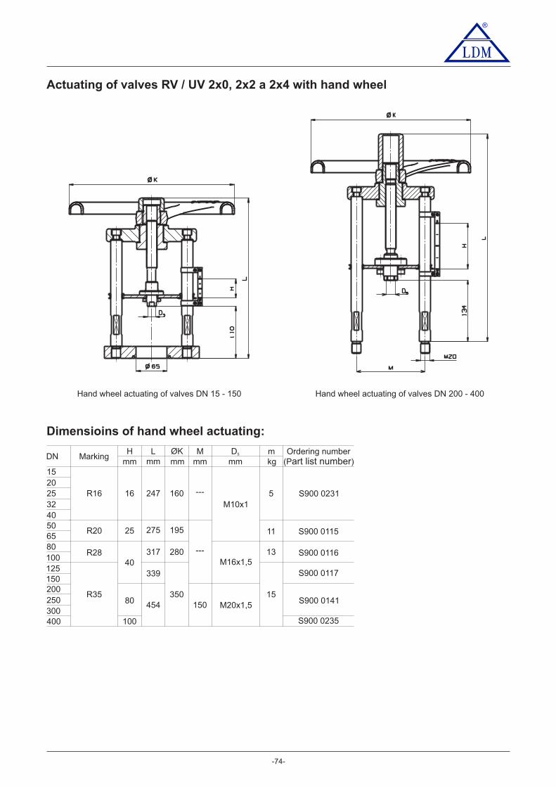
®
-74-
Actuating of valves RV / UV 2x0, 2x2 a 2x4 with hand wheel
Hand wheel actuating of valves DN 15 - 150 Hand wheel actuating of valves DN 200 - 400
Dimensioins of hand wheel actuating:
DN
25324050
mm mm mmmm
6580100125150
317
16
25
MarkingH L mD5
mm
200250300400
454
100
R16
R28
R35
40
80
M
247
339
kg
160
280
350150
---
M20x1,5
M16x1,5
M10x15
13
15
1520
R20
---
275 195 11
Ordering number(P )art list number
S900 0115
S900 0116
S900 0117
S900 0235
S900 0141
S900 0231

®
- -75
Maximal permissible operating pressures [MPa]
Electric actuator Schiebel exrAB3 E Z D
Electric actuator Schiebel AB3 E Z AElectric actuator Schiebel exAB3 E Z BElectric actuator Schiebel rAB3 E Z C
Electric actuator Schiebel AB5 E Z EElectric actuator Schiebel exAB5 E Z F
Electric actuator Schiebel rAB8 E Z KElectric actuator Schiebel exrAB8 E Z LElectric actuator EMG Drehmo D 30 E D AElectric actuator EMG Drehmo D R 30 E D BElectric actuator EMG Drehmo DMI 30 E D CElectric actuator EMG Drehmo DMI R 30 E D DElectric actuator EMG Drehmo D R 30 Ex E D IElectric actuator EMG Drehmo DMI R 30 Ex E D K
Actuator marking in valve specification No.
Electric actuator Modact MTR E P D
Electric actuator PTN 2.20 E R B
Electric actuator PTN 6 E R D
Electric actuator Zepadyn 670 E N C
Electric actuator ST 0 E P K
Electric actuator Isomact ST 1 Ex E P J
Electric actuator Modact MTN, MTP Control E Y AElectric actuator Modact MTN, MTP E Y B
Electric actuator Auma SA 07.1 E AAElectric actuator Auma SA Ex 07.1 E A BElectric actuator Auma SAR 07.1 E A CElectric actuator Auma SAR Ex 07.1 E A D
Electric actuator 660 MIDI E N B
E Q BElectric actuator Rotork Ex IQM 7
Electric actuator ST 0.1 E P L
Electric actuator PTN 2.32; PTN 2.40 E R CE QAElectric actuator Rotork IQM 7
Electric actuator Isomact ST 2 E P M
Electric actuator Auma SA 07.5 E A EElectric actuator Auma SA Ex 07.5 E A FElectric actuator Auma SAR 07.5 E A GElectric actuator Auma SAR Ex 07.5 E A H
Electric actuator Schiebel rAB5 E Z GElectric actuator Schiebel exrAB5 E Z H
Electric actuator Auma SA 10.1 E A IElectric actuator Auma SAR 10.1 E A JElectric actuator Auma SAR Ex 10.1 E A KElectric actuator Auma SA Ex 10.1 E A L
Hand wheel for DN 50 - 65 R 2 2Hand wheel for DN 80 - 100 R 2 8Hand wheel for DN 125 - 400 R 3 5
Hand wheel for DN 15 - 40 R 1 6
Electric actuator PTN 7 E R G
Electric actuator Zepadyn 671 E N E
Electric actuator Modact MTNED, MTPED E Y A
Material PN
Brass 42 3135
Grey cast iron
Spher.cast iron
Cast steel
Chrommolybden
Stainless steel
(CuSn5Zn5Pb5-C)
EN-JL 1040 (EN-GJL-250)
EN-JS 1025
1.0619
(G17CrMo5-5)
(GX5CrNiMoNb19-11-2)
16
16
16
16
16
25
25
40
40
1,60
1,60
1,60
1,56
1,59
---
---
2,50
2,44
4,08
3,98
RT 1) 120 150 200 250 300 375 400 425 4751,60
1,60
1,60
1,32
1,61
1,39
---
---
2,50
2,07
4,02
3,49
1,14
1,44
1,55
1,27
1,58
1,33
---
---
2,43
1,98
3,96
3,33
500Temperature [ C ]o
(EN-GJS-400-18-LT)
(GP240GH)
1.7357
Stainless steel
(GX5CrNi19-10)
16
40
1,52
3,79
1,12
2,82
1,06
2,6525 2,37
4,0040
40 3,9016 1,6325 2,55
25 2,49
1,60
1,60
1,60
1,36
1,44
---
---
2,50
2,13
4,07
3,60
100
1,17
2,941,84
4,00
3,411,632,54
2,25
4,00
3,31
2,51
2,18
1,76 1,66
350 450
3,88
3,17
2,48
2,08
1) -10°C to 50°C
---
1,28
1,47
1,14
1,49
1,25
---
---
2,30
1,78
3,74
3,130,96
2,411,50
3,68
2,84
2,33
1,951.4581
1.4308
---
---
1,39
1,04
1,43
1,17
---
---
2,18
1,62
3,57
2,940,89
2,241,40
3,48
2,60
2,23
1,84
---
---
1,28
0,94
1,33
1,10
---
---
2,00
1,47
3,33
2,750,83
2,081,30
3,20
2,35
2,08
1,72
---
---
1,12
0,88
1,23
1,06
---
---
1,75
1,37
3,09
2,650,79
1,971,23
2,80
2,19
1,93
1,66
---
---
---
0,86
1,20
1,05
---
---
---
1,35
3,00
2,610,77
1,911,20
---
2,16
1,88
1,63
---
---
---
0,84
1,15
1,02
---
---
---
1,32
2,89
2,560,74
1,861,16
---
2,11
1,80
1,60
---
---
---
---
1,11
1,02
---
---
---
---
2,77
2,540,74
1,841,15
---
---
1,73
1,59
---
---
---
---
1,07
1,01
---
---
---
---
2,67
2,520,72
1,801,13
---
---
1,67
1,58
---
---
---
---
1,00
1,00
---
---
---
---
2,50
2,500,71
1,781,11
---
---
1,56
1,56
---
---
---
---
0,89
0,89
---
---
---
---
2,23
2,230,70
1,741,09
---
---
1,39
1,39

Your partner
LDM, reserves the right to modify or improve the designs or specifications of such products at any time without notice
- -76
®
LDM, spol. s r.o.Litomyšlská 1378560 02 eská T ebováČ řCzech Republic
tel.: +420 465 502 511fax: +420 465 533 101E-mail: [email protected]://www.ldm.cz
LDM servis, spol. s r.o.Litomyšlská 1378560 02 eská T ebováČ řCzech Republic
tel.: +420 465 502 411-3fax: +420 465 531 010E-mail: [email protected]
LDM, Polska Sp. z o.o.ul. Bednorza 140-384 KatowicePoland
tel.: +48 32 730 56 33fax: +48 32 730 52 33mobile: +48 601 354 999E-mail: [email protected]
LDM Bratislava s.r.o.Mierová 151821 05 BratislavaSlovakia
tel.: +421 2 43415027-8fax: +421 2 43415029E-mail: [email protected]: www.ldm.sk//
LDM OOD- Bulgaria -z. k. Mladost 1bl. 42, floor 12, app. 571784 SofiaBu garil a
tel.: +359 2 9746311fax: +359 2 9746311
: +359 88 925 766mobile 8E-mail: [email protected]
TOO “ ”LDMShakirova 33/1kab. 103100012 KaragandaKazakhstan
tel.: +7 7212 566 936fax: +7 7212 566 936mobile: +7 701 738 36 79E-mail: [email protected]
.kzhttp://www.ldm
OOO LDM" Promarmatura"Jubilejniy prospekt,dom.6a, of. 601141400 Khimki Moscow RegionRussian Federation
tel.: +7 4957772238fax: +7 4956662212mobile +7 9032254333:E-mail: @inforus ldmvalves.com
LDM Armaturen GmbHWupperweg 21D-51789 LindlarGermany
tel.: +49 2266 440333fax: +49 2266 440372mobile: +49 77 29604691E-mail: [email protected]://www.ldmvalves.com
LDM, spol. s r.o.Office in PraguePodolská 50147 01 Praha 4
tel.: 241087360fax: 241087192E-mail: [email protected]
LDM, spol. s r.o.Office in Ústí nad LabemLadova 2548/38400 11 Ústí nad Labem- Severní Terasa
tel.: 602708257E-mail: [email protected]


![menoymp - t-g.co.ilqop qfi sop [\ qmokr si\ldm^e itktd ho\ee qmm^vef si\ldm^ phtr \pfm[ gig \[m qmmitr ph[ qmm^vef si\ldm^ mgeivi ^igeiv ^iiz qmzrdr hti\kdh ht]e ivm[]h si\ldm^h ^d](https://img.pdfslide.us/doc/110x75/5e36dc1020d37a09f471a66f/menoymp-t-gcoil-qop-qfi-sop-qmokr-sildme-itktd-hoee-qmmvef-sildm-phtr.jpg)


![Oracle VM Server for SPARC 2.2 Reference Manual · ldm–command-lineinterfacefortheLogicalDomainsManager ldm or ldm --help [subcommand] ldm -V ldm add-domain -i file ldm add-domain](https://img.pdfslide.us/doc/110x75/605369a0738d750ee64c89bb/oracle-vm-server-for-sparc-22-reference-manual-ldmacommand-lineinterfaceforthelogicaldomainsmanager.jpg)