Embed Size (px)
DESCRIPTION
ertet
Citation preview
9: Capacitors and Inductors
9: Capacitors and Inductors
• Capacitors
• Types of Capacitor
• Inductors
• Passive Components
• Series and ParallelInductors• Series and ParallelCapacitors
• Current/Voltage Continuity
• Average Current/Voltage
• Buck Converter
• Power and Energy
• Summary
E1.1 Analysis of Circuits (2014-5424) Capacitors and Inductors: 9 – 1 / 12
Capacitors
9: Capacitors and Inductors
• Capacitors
• Types of Capacitor
• Inductors
• Passive Components
• Series and ParallelInductors• Series and ParallelCapacitors
• Current/Voltage Continuity
• Average Current/Voltage
• Buck Converter
• Power and Energy
• Summary
E1.1 Analysis of Circuits (2014-5424) Capacitors and Inductors: 9 – 2 / 12
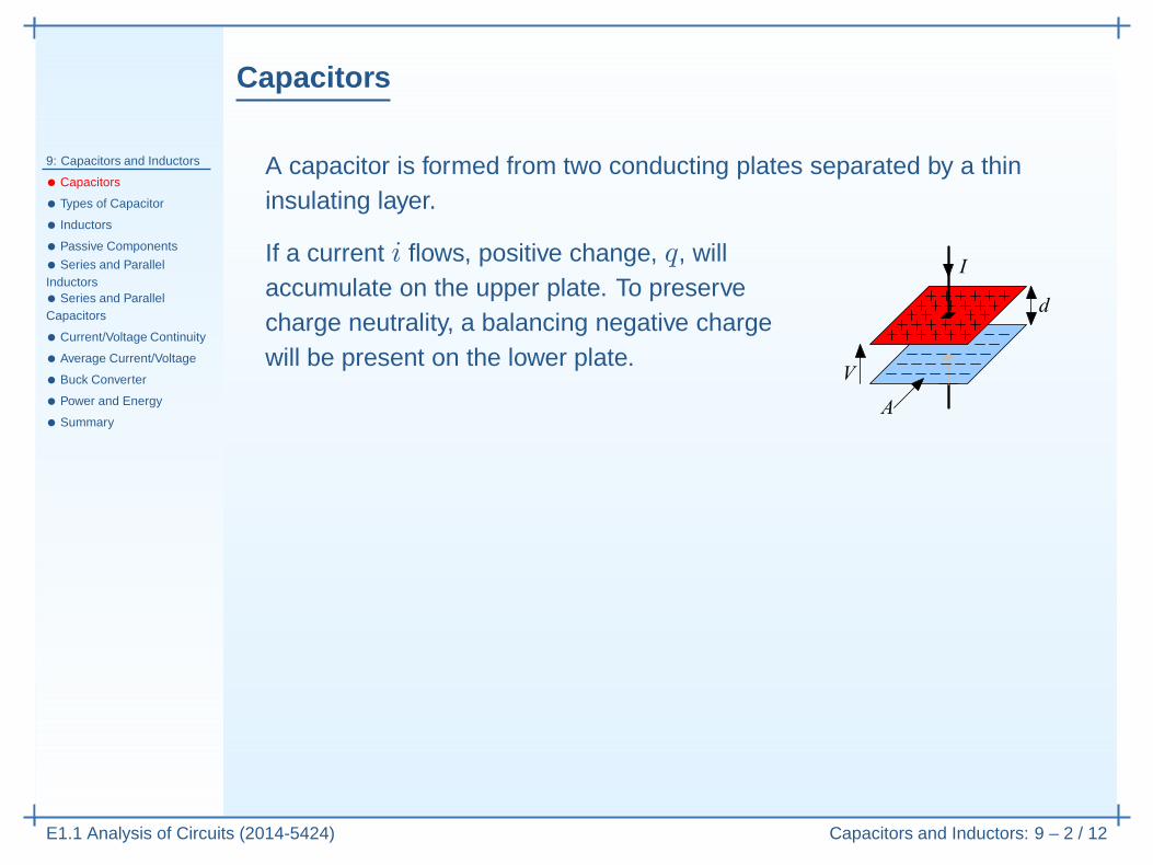
A capacitor is formed from two conducting plates separated by a thininsulating layer.
If a current i flows, positive change, q, willaccumulate on the upper plate. To preservecharge neutrality, a balancing negative chargewill be present on the lower plate.
Capacitors
9: Capacitors and Inductors
• Capacitors
• Types of Capacitor
• Inductors
• Passive Components
• Series and ParallelInductors• Series and ParallelCapacitors
• Current/Voltage Continuity
• Average Current/Voltage
• Buck Converter
• Power and Energy
• Summary
E1.1 Analysis of Circuits (2014-5424) Capacitors and Inductors: 9 – 2 / 12
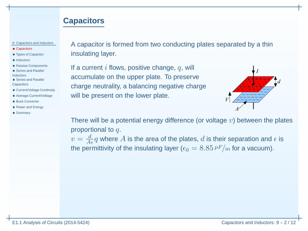
A capacitor is formed from two conducting plates separated by a thininsulating layer.
If a current i flows, positive change, q, willaccumulate on the upper plate. To preservecharge neutrality, a balancing negative chargewill be present on the lower plate.
There will be a potential energy difference (or voltage v) between the platesproportional to q.v = d
Aǫq where A is the area of the plates, d is their separation and ǫ is
the permittivity of the insulating layer (ǫ0 = 8.85 pF/m for a vacuum).
Capacitors
9: Capacitors and Inductors
• Capacitors
• Types of Capacitor
• Inductors
• Passive Components
• Series and ParallelInductors• Series and ParallelCapacitors
• Current/Voltage Continuity
• Average Current/Voltage
• Buck Converter
• Power and Energy
• Summary
E1.1 Analysis of Circuits (2014-5424) Capacitors and Inductors: 9 – 2 / 12
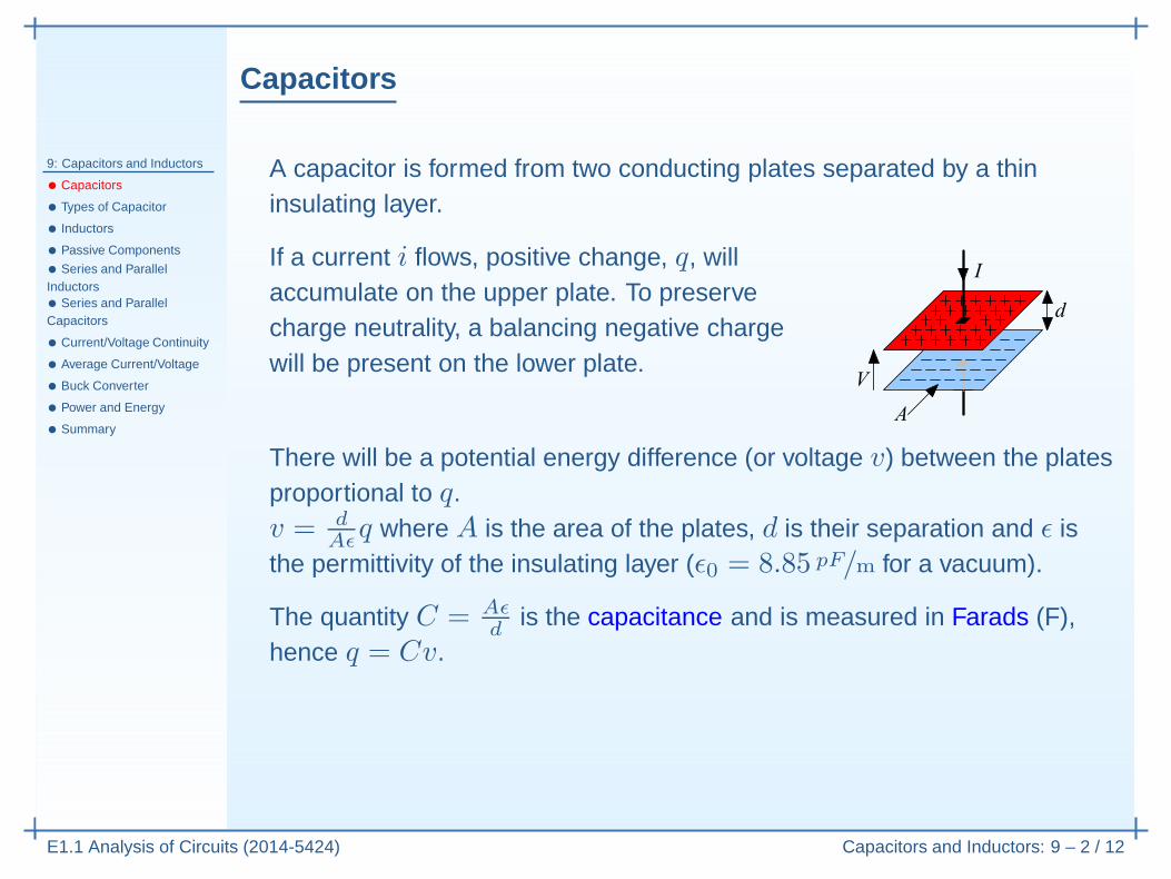
A capacitor is formed from two conducting plates separated by a thininsulating layer.
If a current i flows, positive change, q, willaccumulate on the upper plate. To preservecharge neutrality, a balancing negative chargewill be present on the lower plate.
There will be a potential energy difference (or voltage v) between the platesproportional to q.v = d
Aǫq where A is the area of the plates, d is their separation and ǫ is
the permittivity of the insulating layer (ǫ0 = 8.85 pF/m for a vacuum).
The quantity C = Aǫd
is the capacitance and is measured in Farads (F),hence q = Cv.
Capacitors
9: Capacitors and Inductors
• Capacitors
• Types of Capacitor
• Inductors
• Passive Components
• Series and ParallelInductors• Series and ParallelCapacitors
• Current/Voltage Continuity
• Average Current/Voltage
• Buck Converter
• Power and Energy
• Summary
E1.1 Analysis of Circuits (2014-5424) Capacitors and Inductors: 9 – 2 / 12
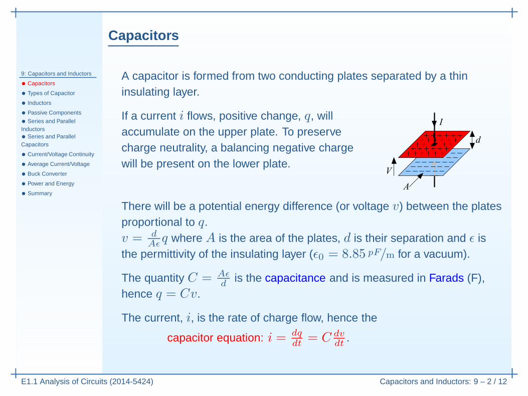
A capacitor is formed from two conducting plates separated by a thininsulating layer.
If a current i flows, positive change, q, willaccumulate on the upper plate. To preservecharge neutrality, a balancing negative chargewill be present on the lower plate.
There will be a potential energy difference (or voltage v) between the platesproportional to q.v = d
Aǫq where A is the area of the plates, d is their separation and ǫ is
the permittivity of the insulating layer (ǫ0 = 8.85 pF/m for a vacuum).
The quantity C = Aǫd
is the capacitance and is measured in Farads (F),hence q = Cv.
The current, i, is the rate of charge flow, hence the
capacitor equation: i = dqdt
= C dvdt
.
Types of Capacitor
9: Capacitors and Inductors
• Capacitors
• Types of Capacitor
• Inductors
• Passive Components
• Series and ParallelInductors• Series and ParallelCapacitors
• Current/Voltage Continuity
• Average Current/Voltage
• Buck Converter
• Power and Energy
• Summary
E1.1 Analysis of Circuits (2014-5424) Capacitors and Inductors: 9 – 3 / 12
Capacitor symbol represents the two separatedplates. Capacitor types are distinguished bythe material used as the insulator.
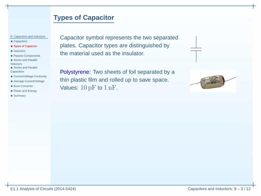
Polystyrene: Two sheets of foil separated by athin plastic film and rolled up to save space.Values: 10 pF to 1 nF.
Types of Capacitor
9: Capacitors and Inductors
• Capacitors
• Types of Capacitor
• Inductors
• Passive Components
• Series and ParallelInductors• Series and ParallelCapacitors
• Current/Voltage Continuity
• Average Current/Voltage
• Buck Converter
• Power and Energy
• Summary
E1.1 Analysis of Circuits (2014-5424) Capacitors and Inductors: 9 – 3 / 12
Capacitor symbol represents the two separatedplates. Capacitor types are distinguished bythe material used as the insulator.
Polystyrene: Two sheets of foil separated by athin plastic film and rolled up to save space.Values: 10 pF to 1 nF.
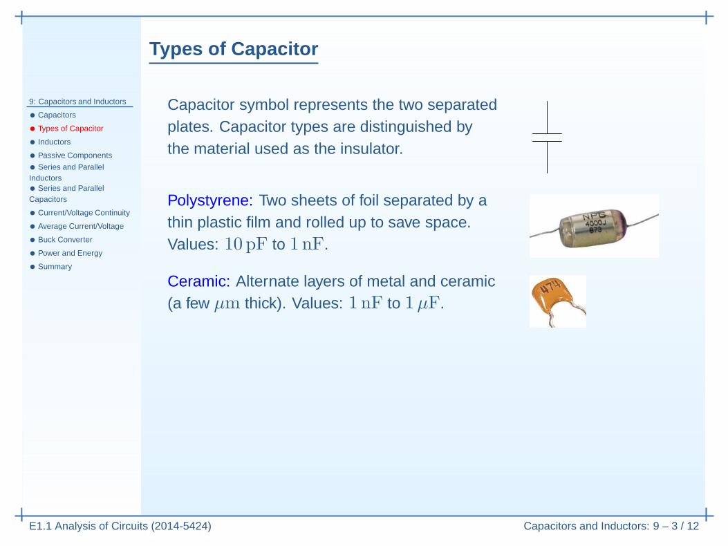
Ceramic: Alternate layers of metal and ceramic(a few µm thick). Values: 1 nF to 1µF.
Types of Capacitor
9: Capacitors and Inductors
• Capacitors
• Types of Capacitor
• Inductors
• Passive Components
• Series and ParallelInductors• Series and ParallelCapacitors
• Current/Voltage Continuity
• Average Current/Voltage
• Buck Converter
• Power and Energy
• Summary
E1.1 Analysis of Circuits (2014-5424) Capacitors and Inductors: 9 – 3 / 12
Capacitor symbol represents the two separatedplates. Capacitor types are distinguished bythe material used as the insulator.
Polystyrene: Two sheets of foil separated by athin plastic film and rolled up to save space.Values: 10 pF to 1 nF.
Ceramic: Alternate layers of metal and ceramic(a few µm thick). Values: 1 nF to 1µF.
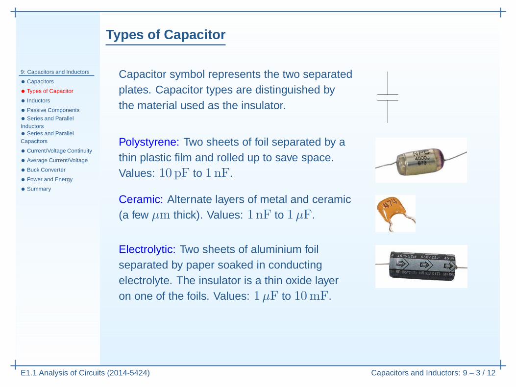
Electrolytic: Two sheets of aluminium foilseparated by paper soaked in conductingelectrolyte. The insulator is a thin oxide layeron one of the foils. Values: 1µF to 10mF.
Types of Capacitor
9: Capacitors and Inductors
• Capacitors
• Types of Capacitor
• Inductors
• Passive Components
• Series and ParallelInductors• Series and ParallelCapacitors
• Current/Voltage Continuity
• Average Current/Voltage
• Buck Converter
• Power and Energy
• Summary
E1.1 Analysis of Circuits (2014-5424) Capacitors and Inductors: 9 – 3 / 12
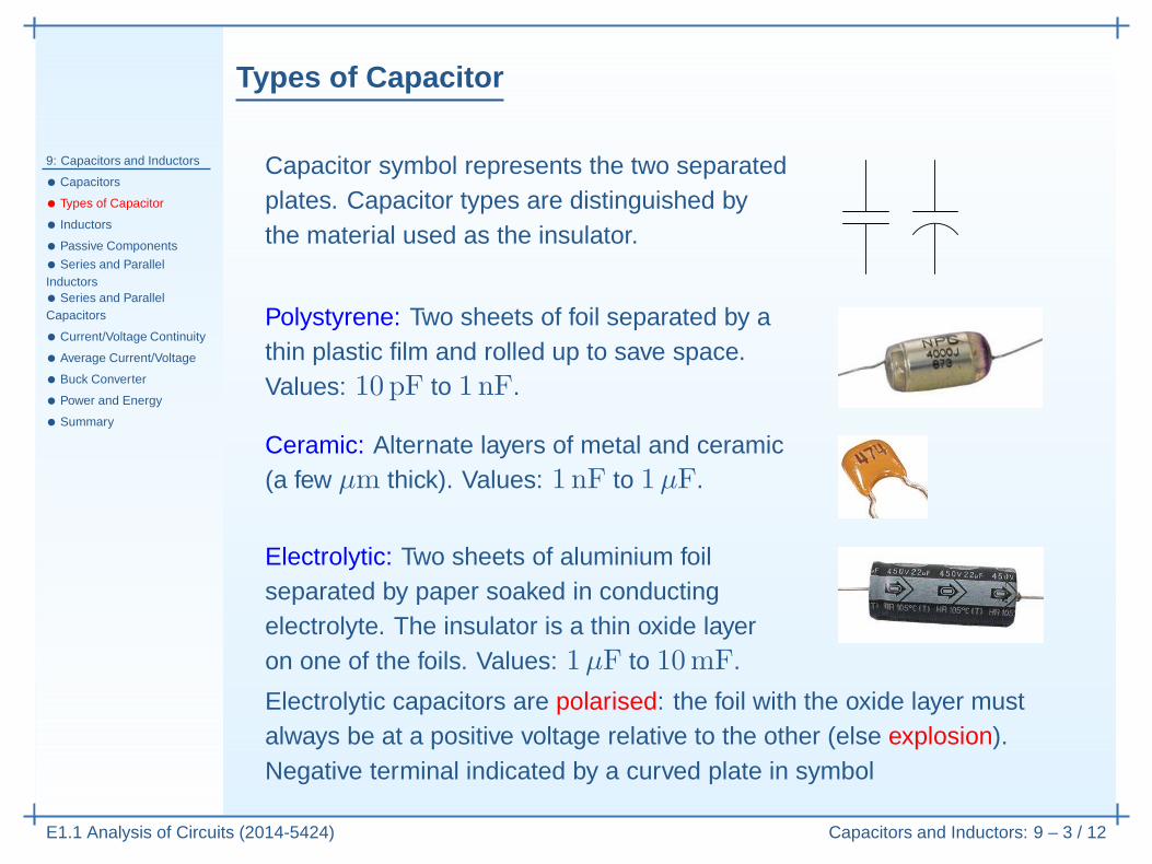
Capacitor symbol represents the two separatedplates. Capacitor types are distinguished bythe material used as the insulator.
Polystyrene: Two sheets of foil separated by athin plastic film and rolled up to save space.Values: 10 pF to 1 nF.
Ceramic: Alternate layers of metal and ceramic(a few µm thick). Values: 1 nF to 1µF.
Electrolytic: Two sheets of aluminium foilseparated by paper soaked in conductingelectrolyte. The insulator is a thin oxide layeron one of the foils. Values: 1µF to 10mF.
Electrolytic capacitors are polarised: the foil with the oxide layer mustalways be at a positive voltage relative to the other (else explosion).Negative terminal indicated by a curved plate in symbol

Types of Capacitor
9: Capacitors and Inductors
• Capacitors
• Types of Capacitor
• Inductors
• Passive Components
• Series and ParallelInductors• Series and ParallelCapacitors
• Current/Voltage Continuity
• Average Current/Voltage
• Buck Converter
• Power and Energy
• Summary
E1.1 Analysis of Circuits (2014-5424) Capacitors and Inductors: 9 – 3 / 12
Capacitor symbol represents the two separatedplates. Capacitor types are distinguished bythe material used as the insulator.
Polystyrene: Two sheets of foil separated by athin plastic film and rolled up to save space.Values: 10 pF to 1 nF.
Ceramic: Alternate layers of metal and ceramic(a few µm thick). Values: 1 nF to 1µF.
Electrolytic: Two sheets of aluminium foilseparated by paper soaked in conductingelectrolyte. The insulator is a thin oxide layeron one of the foils. Values: 1µF to 10mF.
Electrolytic capacitors are polarised: the foil with the oxide layer mustalways be at a positive voltage relative to the other (else explosion).Negative terminal indicated by a curved plate in symbol or “-”.
Inductors
9: Capacitors and Inductors
• Capacitors
• Types of Capacitor
• Inductors
• Passive Components
• Series and ParallelInductors• Series and ParallelCapacitors
• Current/Voltage Continuity
• Average Current/Voltage
• Buck Converter
• Power and Energy
• Summary
E1.1 Analysis of Circuits (2014-5424) Capacitors and Inductors: 9 – 4 / 12
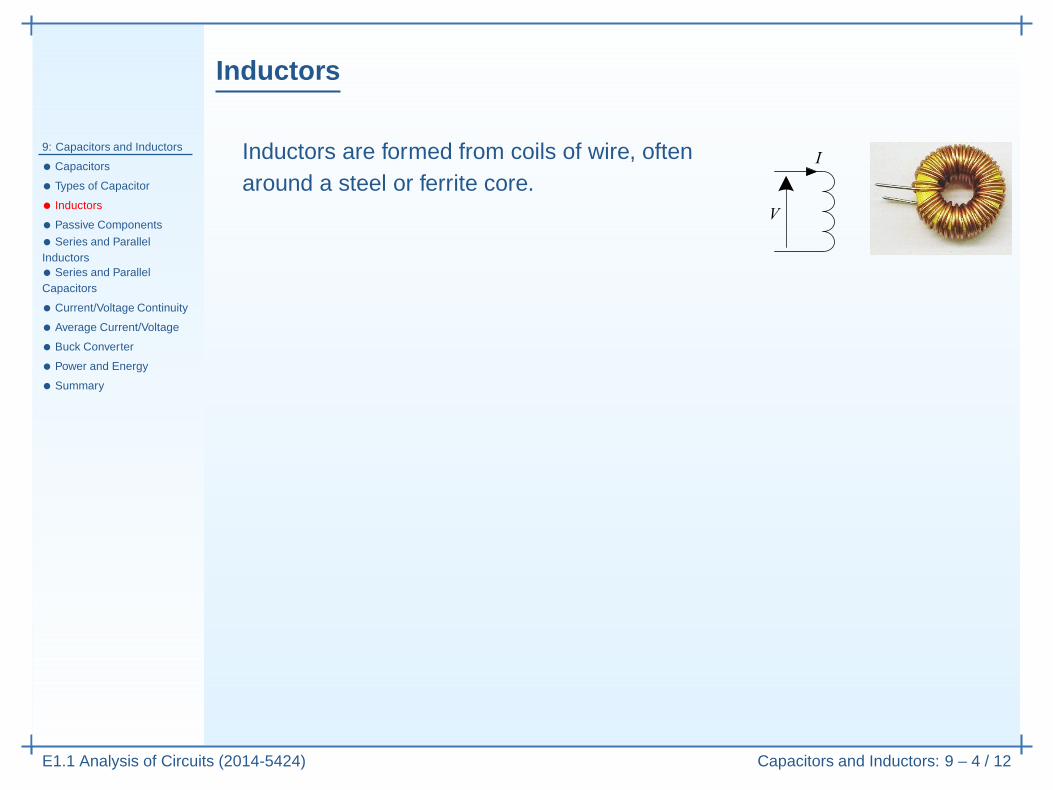
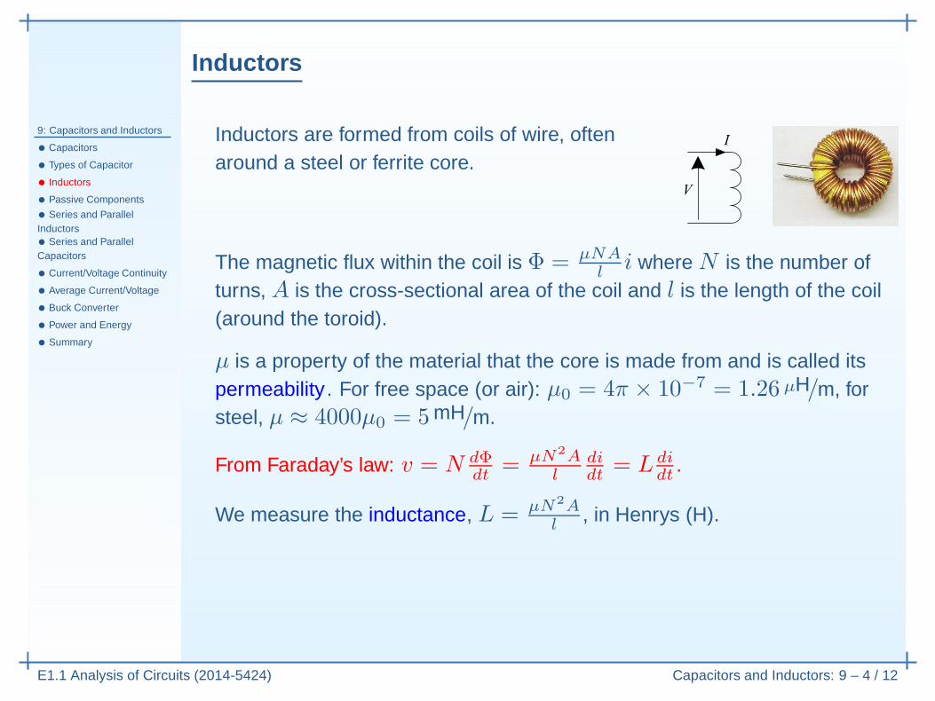
Inductors are formed from coils of wire, oftenaround a steel or ferrite core.
Inductors
9: Capacitors and Inductors
• Capacitors
• Types of Capacitor
• Inductors
• Passive Components
• Series and ParallelInductors• Series and ParallelCapacitors
• Current/Voltage Continuity
• Average Current/Voltage
• Buck Converter
• Power and Energy
• Summary
E1.1 Analysis of Circuits (2014-5424) Capacitors and Inductors: 9 – 4 / 12
Inductors are formed from coils of wire, oftenaround a steel or ferrite core.
The magnetic flux within the coil is Φ = µNAl
i where N is the number ofturns, A is the cross-sectional area of the coil and l is the length of the coil(around the toroid).
µ is a property of the material that the core is made from and is called itspermeability . For free space (or air): µ0 = 4π × 10−7 = 1.26 µH/m, forsteel, µ ≈ 4000µ0 = 5mH/m.
Inductors
9: Capacitors and Inductors
• Capacitors
• Types of Capacitor
• Inductors
• Passive Components
• Series and ParallelInductors• Series and ParallelCapacitors
• Current/Voltage Continuity
• Average Current/Voltage
• Buck Converter
• Power and Energy
• Summary
E1.1 Analysis of Circuits (2014-5424) Capacitors and Inductors: 9 – 4 / 12
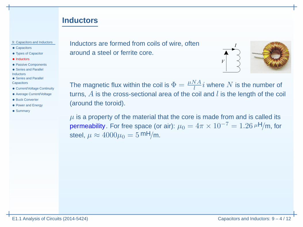
Inductors are formed from coils of wire, oftenaround a steel or ferrite core.
The magnetic flux within the coil is Φ = µNAl
i where N is the number ofturns, A is the cross-sectional area of the coil and l is the length of the coil(around the toroid).
µ is a property of the material that the core is made from and is called itspermeability . For free space (or air): µ0 = 4π × 10−7 = 1.26 µH/m, forsteel, µ ≈ 4000µ0 = 5mH/m.
From Faraday’s law: v = N dΦdt
= µN2Al
didt
= L didt
.
Inductors
9: Capacitors and Inductors
• Capacitors
• Types of Capacitor
• Inductors
• Passive Components
• Series and ParallelInductors• Series and ParallelCapacitors
• Current/Voltage Continuity
• Average Current/Voltage
• Buck Converter
• Power and Energy
• Summary
E1.1 Analysis of Circuits (2014-5424) Capacitors and Inductors: 9 – 4 / 12
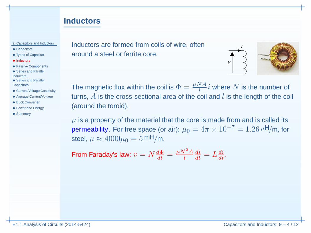
Inductors are formed from coils of wire, oftenaround a steel or ferrite core.
The magnetic flux within the coil is Φ = µNAl
i where N is the number ofturns, A is the cross-sectional area of the coil and l is the length of the coil(around the toroid).
µ is a property of the material that the core is made from and is called itspermeability . For free space (or air): µ0 = 4π × 10−7 = 1.26 µH/m, forsteel, µ ≈ 4000µ0 = 5mH/m.
From Faraday’s law: v = N dΦdt
= µN2Al
didt
= L didt
.
We measure the inductance, L = µN2Al
, in Henrys (H).
Passive Components
9: Capacitors and Inductors
• Capacitors
• Types of Capacitor
• Inductors
• Passive Components
• Series and ParallelInductors• Series and ParallelCapacitors
• Current/Voltage Continuity
• Average Current/Voltage
• Buck Converter
• Power and Energy
• Summary
E1.1 Analysis of Circuits (2014-5424) Capacitors and Inductors: 9 – 5 / 12
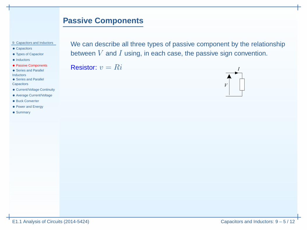
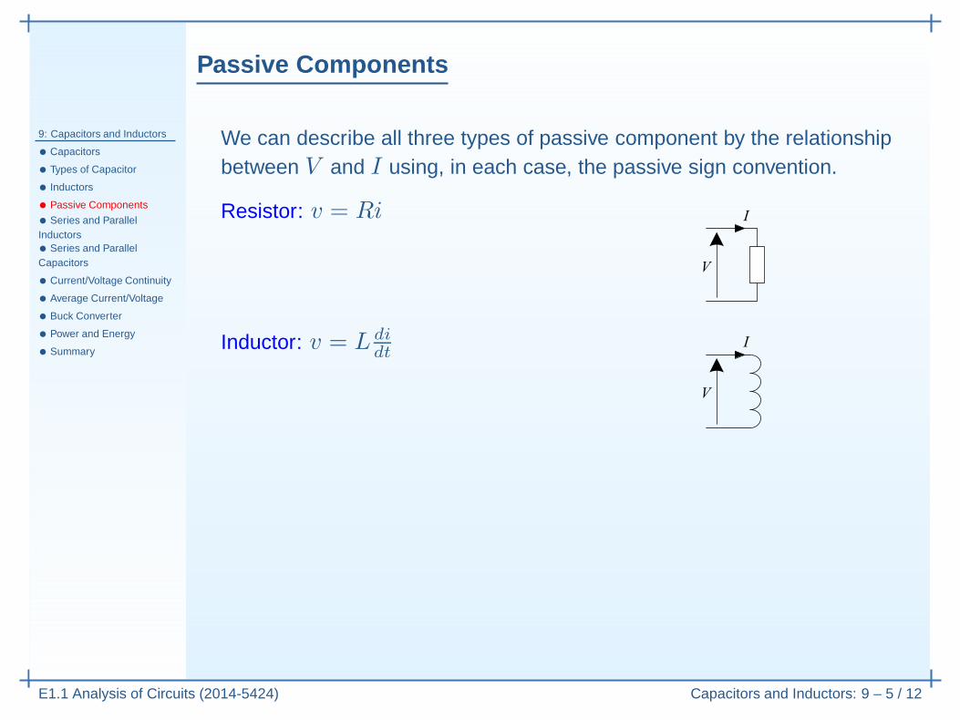
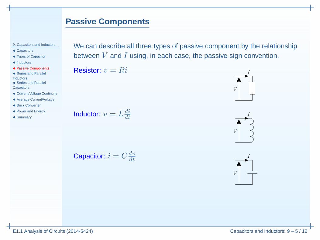
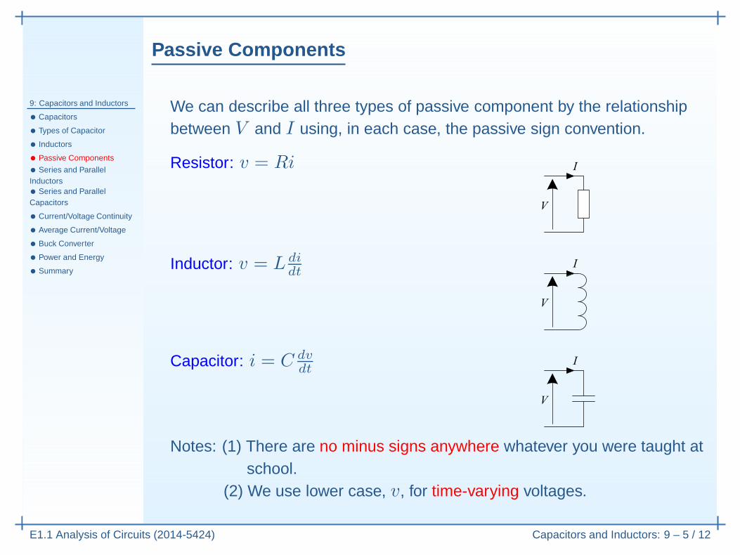
We can describe all three types of passive component by the relationshipbetween V and I using, in each case, the passive sign convention.
Passive Components
9: Capacitors and Inductors
• Capacitors
• Types of Capacitor
• Inductors
• Passive Components
• Series and ParallelInductors• Series and ParallelCapacitors
• Current/Voltage Continuity
• Average Current/Voltage
• Buck Converter
• Power and Energy
• Summary
E1.1 Analysis of Circuits (2014-5424) Capacitors and Inductors: 9 – 5 / 12
We can describe all three types of passive component by the relationshipbetween V and I using, in each case, the passive sign convention.
Resistor: v = Ri
Inductor: v = L didt
Capacitor: i = C dvdt
Notes: (1) There are no minus signs anywhere whatever you were taught atschool.
(2) We use lower case, v, for time-varying voltages.
Series and Parallel Inductors
9: Capacitors and Inductors
• Capacitors
• Types of Capacitor
• Inductors
• Passive Components
• Series and ParallelInductors• Series and ParallelCapacitors
• Current/Voltage Continuity
• Average Current/Voltage
• Buck Converter
• Power and Energy
• Summary
E1.1 Analysis of Circuits (2014-5424) Capacitors and Inductors: 9 – 6 / 12
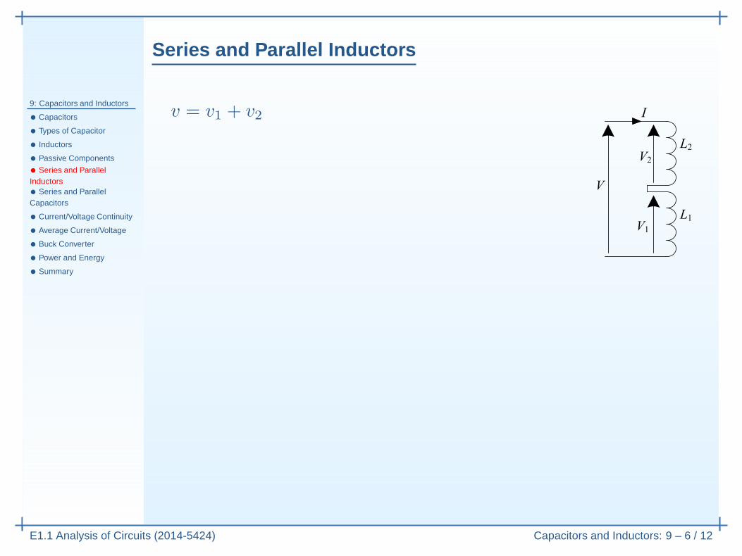
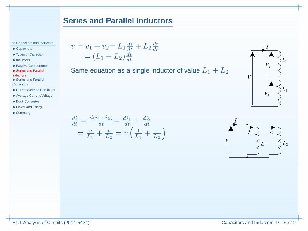
v = v1 + v2
Series and Parallel Inductors
9: Capacitors and Inductors
• Capacitors
• Types of Capacitor
• Inductors
• Passive Components
• Series and ParallelInductors• Series and ParallelCapacitors
• Current/Voltage Continuity
• Average Current/Voltage
• Buck Converter
• Power and Energy
• Summary
E1.1 Analysis of Circuits (2014-5424) Capacitors and Inductors: 9 – 6 / 12
v = v1 + v2= L1didt
+ L2didt
= (L1 + L2)didt
Series and Parallel Inductors
9: Capacitors and Inductors
• Capacitors
• Types of Capacitor
• Inductors
• Passive Components
• Series and ParallelInductors• Series and ParallelCapacitors
• Current/Voltage Continuity
• Average Current/Voltage
• Buck Converter
• Power and Energy
• Summary
E1.1 Analysis of Circuits (2014-5424) Capacitors and Inductors: 9 – 6 / 12
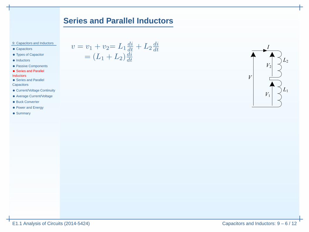
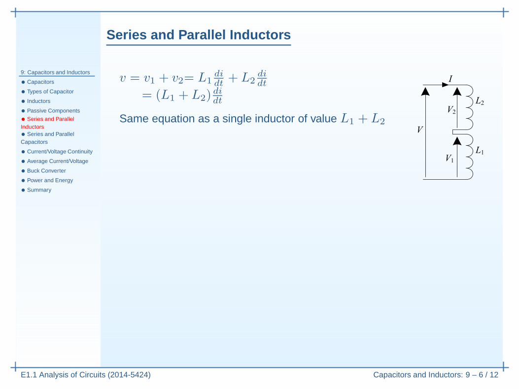
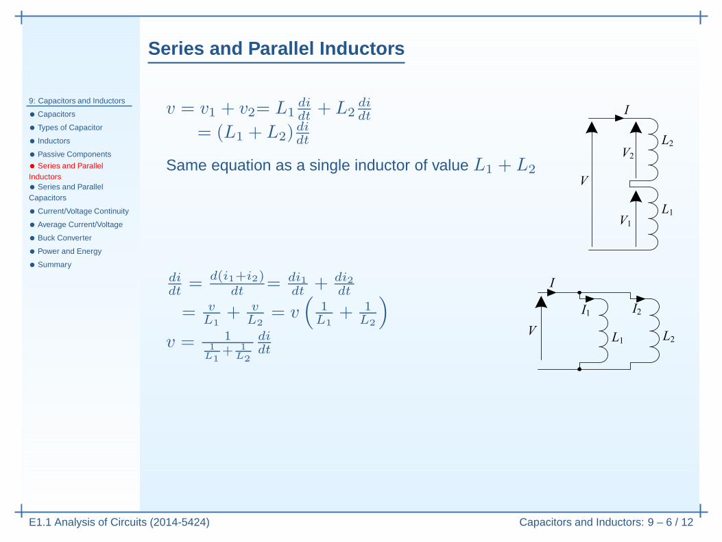
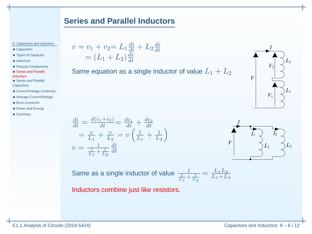
v = v1 + v2= L1didt
+ L2didt
= (L1 + L2)didt
Same equation as a single inductor of value L1 + L2
Series and Parallel Inductors
9: Capacitors and Inductors
• Capacitors
• Types of Capacitor
• Inductors
• Passive Components
• Series and ParallelInductors• Series and ParallelCapacitors
• Current/Voltage Continuity
• Average Current/Voltage
• Buck Converter
• Power and Energy
• Summary
E1.1 Analysis of Circuits (2014-5424) Capacitors and Inductors: 9 – 6 / 12
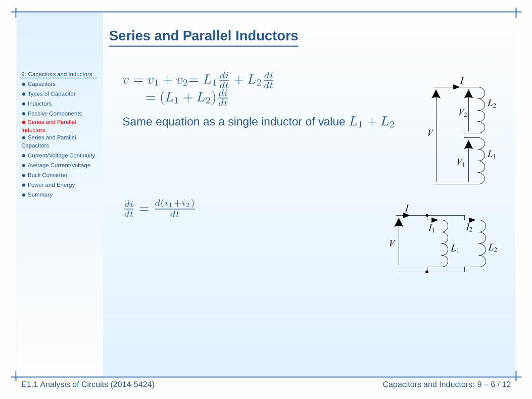
v = v1 + v2= L1didt
+ L2didt
= (L1 + L2)didt
Same equation as a single inductor of value L1 + L2
didt
= d(i1+i2)dt
Series and Parallel Inductors
9: Capacitors and Inductors
• Capacitors
• Types of Capacitor
• Inductors
• Passive Components
• Series and ParallelInductors• Series and ParallelCapacitors
• Current/Voltage Continuity
• Average Current/Voltage
• Buck Converter
• Power and Energy
• Summary
E1.1 Analysis of Circuits (2014-5424) Capacitors and Inductors: 9 – 6 / 12
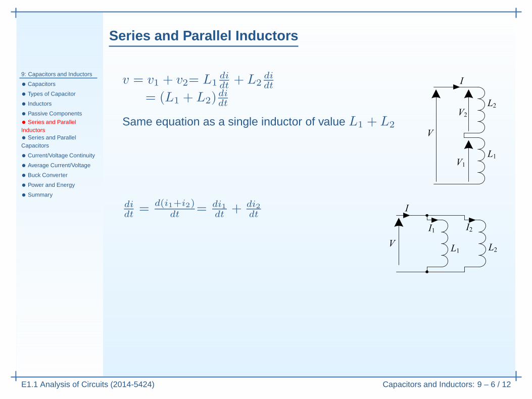
v = v1 + v2= L1didt
+ L2didt
= (L1 + L2)didt
Same equation as a single inductor of value L1 + L2
didt
= d(i1+i2)dt
= di1dt
+ di2dt
Series and Parallel Inductors
9: Capacitors and Inductors
• Capacitors
• Types of Capacitor
• Inductors
• Passive Components
• Series and ParallelInductors• Series and ParallelCapacitors
• Current/Voltage Continuity
• Average Current/Voltage
• Buck Converter
• Power and Energy
• Summary
E1.1 Analysis of Circuits (2014-5424) Capacitors and Inductors: 9 – 6 / 12
v = v1 + v2= L1didt
+ L2didt
= (L1 + L2)didt
Same equation as a single inductor of value L1 + L2
didt
= d(i1+i2)dt
= di1dt
+ di2dt
= vL1
+ vL2
= v(
1L1
+ 1L2
)
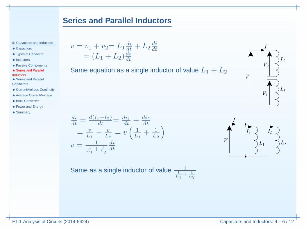
v = 11
L1+ 1
L2
didt
Series and Parallel Inductors
9: Capacitors and Inductors
• Capacitors
• Types of Capacitor
• Inductors
• Passive Components
• Series and ParallelInductors• Series and ParallelCapacitors
• Current/Voltage Continuity
• Average Current/Voltage
• Buck Converter
• Power and Energy
• Summary
E1.1 Analysis of Circuits (2014-5424) Capacitors and Inductors: 9 – 6 / 12
v = v1 + v2= L1didt
+ L2didt
= (L1 + L2)didt
Same equation as a single inductor of value L1 + L2
didt
= d(i1+i2)dt
= di1dt
+ di2dt
= vL1
+ vL2
= v(
1L1
+ 1L2
)
v = 11
L1+ 1
L2
didt
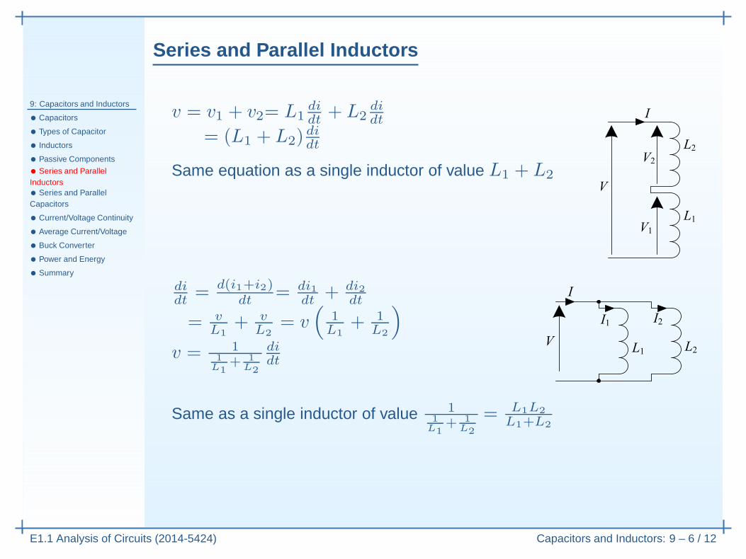
Same as a single inductor of value 11
L1+ 1
L2
Series and Parallel Inductors
9: Capacitors and Inductors
• Capacitors
• Types of Capacitor
• Inductors
• Passive Components
• Series and ParallelInductors• Series and ParallelCapacitors
• Current/Voltage Continuity
• Average Current/Voltage
• Buck Converter
• Power and Energy
• Summary
E1.1 Analysis of Circuits (2014-5424) Capacitors and Inductors: 9 – 6 / 12
v = v1 + v2= L1didt
+ L2didt
= (L1 + L2)didt
Same equation as a single inductor of value L1 + L2
didt
= d(i1+i2)dt
= di1dt
+ di2dt
= vL1
+ vL2
= v(
1L1
+ 1L2
)
v = 11
L1+ 1
L2
didt
Same as a single inductor of value 11
L1+ 1
L2
= L1L2
L1+L2
Inductors combine just like resistors.
Series and Parallel Capacitors
9: Capacitors and Inductors
• Capacitors
• Types of Capacitor
• Inductors
• Passive Components
• Series and ParallelInductors• Series and ParallelCapacitors
• Current/Voltage Continuity
• Average Current/Voltage
• Buck Converter
• Power and Energy
• Summary
E1.1 Analysis of Circuits (2014-5424) Capacitors and Inductors: 9 – 7 / 12
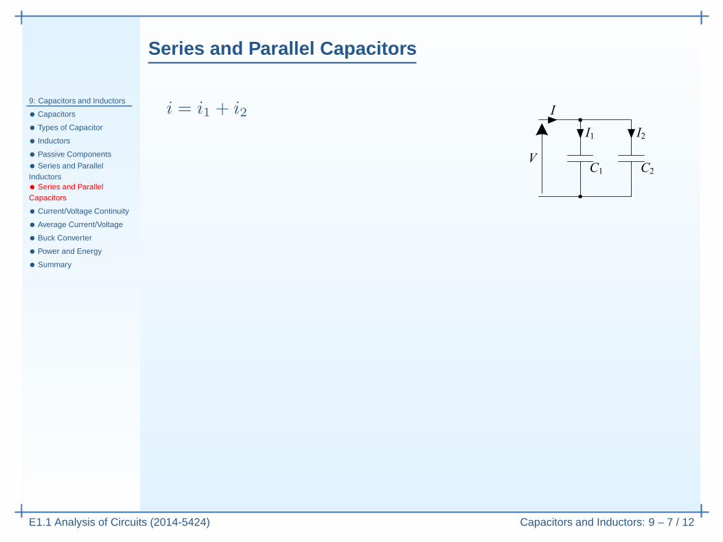
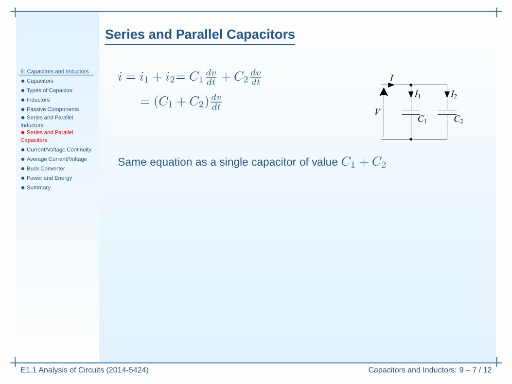
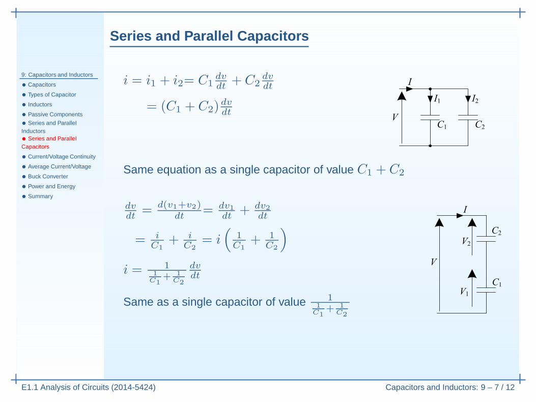
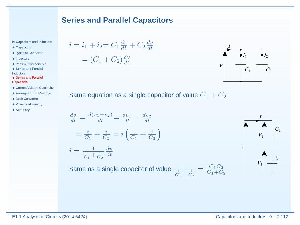
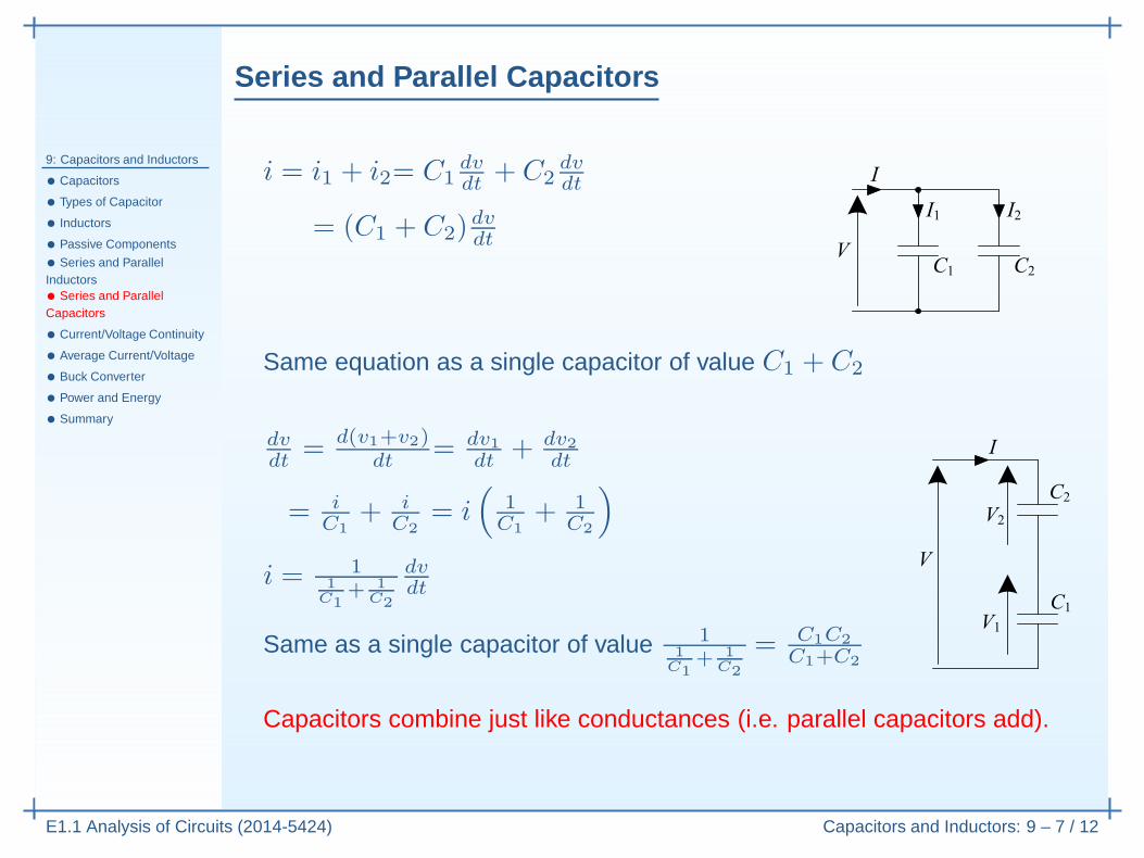
i = i1 + i2
Series and Parallel Capacitors
9: Capacitors and Inductors
• Capacitors
• Types of Capacitor
• Inductors
• Passive Components
• Series and ParallelInductors• Series and ParallelCapacitors
• Current/Voltage Continuity
• Average Current/Voltage
• Buck Converter
• Power and Energy
• Summary
E1.1 Analysis of Circuits (2014-5424) Capacitors and Inductors: 9 – 7 / 12
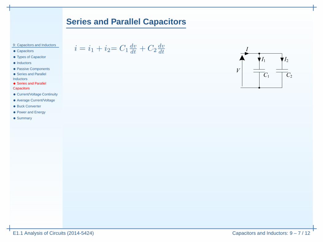
i = i1 + i2= C1dvdt
+ C2dvdt
Series and Parallel Capacitors
9: Capacitors and Inductors
• Capacitors
• Types of Capacitor
• Inductors
• Passive Components
• Series and ParallelInductors• Series and ParallelCapacitors
• Current/Voltage Continuity
• Average Current/Voltage
• Buck Converter
• Power and Energy
• Summary
E1.1 Analysis of Circuits (2014-5424) Capacitors and Inductors: 9 – 7 / 12
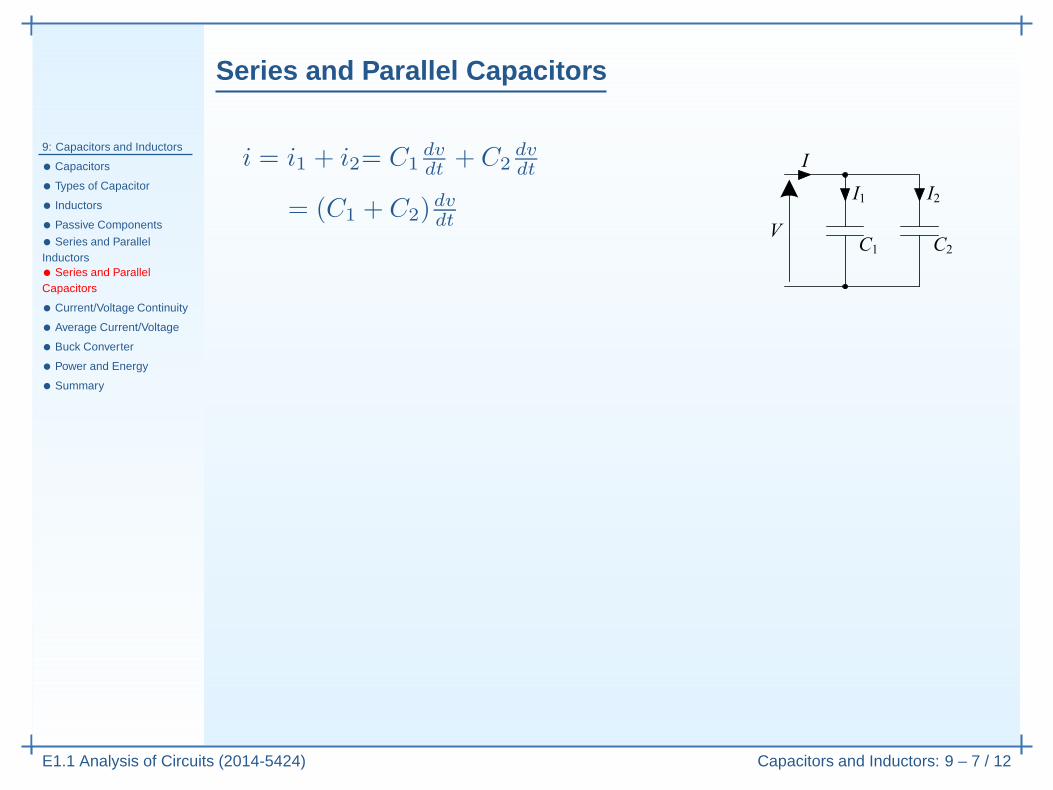
i = i1 + i2= C1dvdt
+ C2dvdt
= (C1 + C2)dvdt
Series and Parallel Capacitors
9: Capacitors and Inductors
• Capacitors
• Types of Capacitor
• Inductors
• Passive Components
• Series and ParallelInductors• Series and ParallelCapacitors
• Current/Voltage Continuity
• Average Current/Voltage
• Buck Converter
• Power and Energy
• Summary
E1.1 Analysis of Circuits (2014-5424) Capacitors and Inductors: 9 – 7 / 12
i = i1 + i2= C1dvdt
+ C2dvdt
= (C1 + C2)dvdt
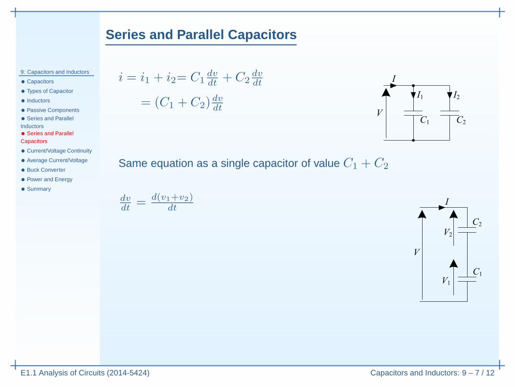
Same equation as a single capacitor of value C1 + C2
Series and Parallel Capacitors
9: Capacitors and Inductors
• Capacitors
• Types of Capacitor
• Inductors
• Passive Components
• Series and ParallelInductors• Series and ParallelCapacitors
• Current/Voltage Continuity
• Average Current/Voltage
• Buck Converter
• Power and Energy
• Summary
E1.1 Analysis of Circuits (2014-5424) Capacitors and Inductors: 9 – 7 / 12
i = i1 + i2= C1dvdt
+ C2dvdt
= (C1 + C2)dvdt
Same equation as a single capacitor of value C1 + C2
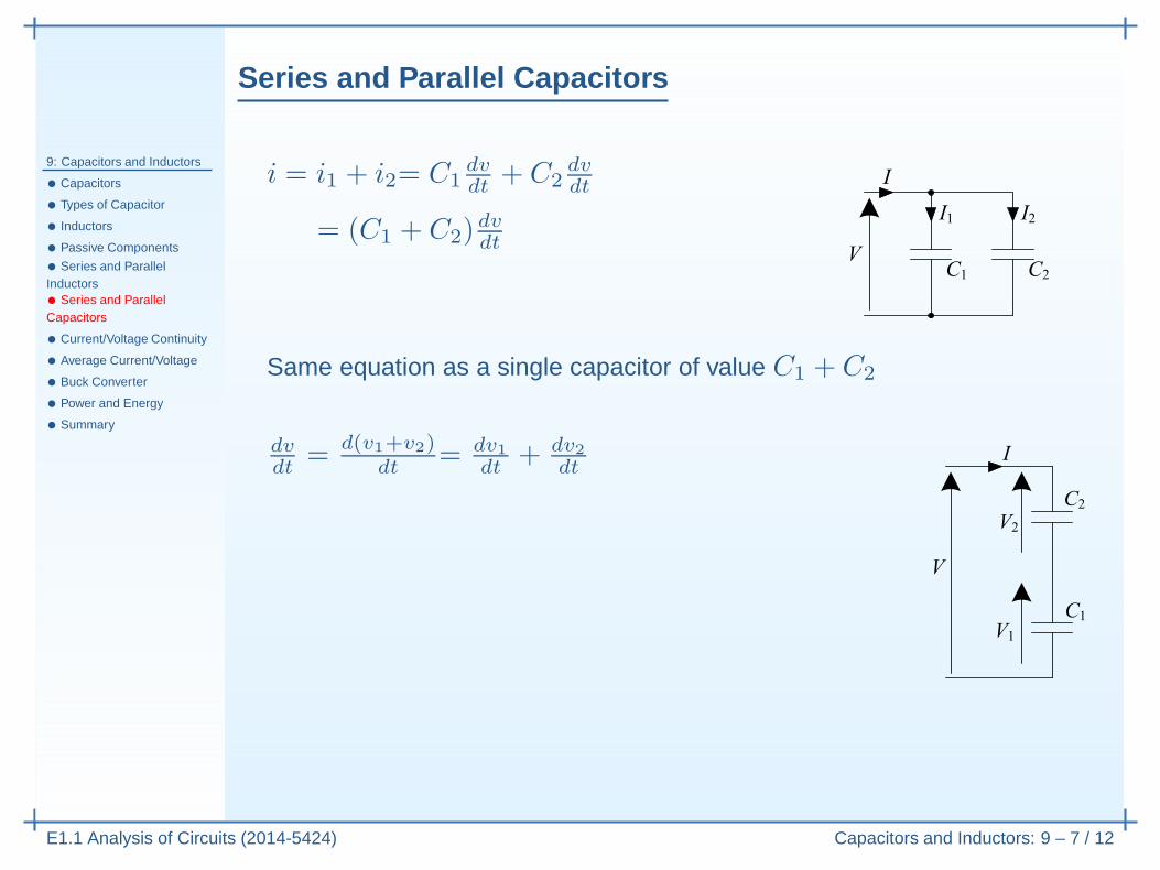
dvdt
= d(v1+v2)dt
Series and Parallel Capacitors
9: Capacitors and Inductors
• Capacitors
• Types of Capacitor
• Inductors
• Passive Components
• Series and ParallelInductors• Series and ParallelCapacitors
• Current/Voltage Continuity
• Average Current/Voltage
• Buck Converter
• Power and Energy
• Summary
E1.1 Analysis of Circuits (2014-5424) Capacitors and Inductors: 9 – 7 / 12
i = i1 + i2= C1dvdt
+ C2dvdt
= (C1 + C2)dvdt
Same equation as a single capacitor of value C1 + C2
dvdt
= d(v1+v2)dt
= dv1dt
+ dv2dt
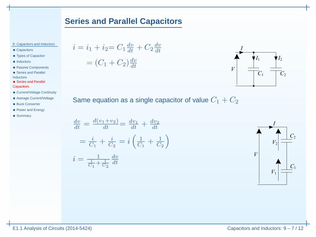
= iC1
+ iC2
= i(
1C1
+ 1C2
)
Series and Parallel Capacitors
9: Capacitors and Inductors
• Capacitors
• Types of Capacitor
• Inductors
• Passive Components
• Series and ParallelInductors• Series and ParallelCapacitors
• Current/Voltage Continuity
• Average Current/Voltage
• Buck Converter
• Power and Energy
• Summary
E1.1 Analysis of Circuits (2014-5424) Capacitors and Inductors: 9 – 7 / 12
i = i1 + i2= C1dvdt
+ C2dvdt
= (C1 + C2)dvdt
Same equation as a single capacitor of value C1 + C2
dvdt
= d(v1+v2)dt
= dv1dt
+ dv2dt
= iC1
+ iC2
= i(
1C1
+ 1C2
)
i = 11
C1+ 1
C2
dvdt
Same as a single capacitor of value 11
C1+ 1
C2
= C1C2
C1+C2
Capacitors combine just like conductances (i.e. parallel capacitors add).
Current/Voltage Continuity
9: Capacitors and Inductors
• Capacitors
• Types of Capacitor
• Inductors
• Passive Components
• Series and ParallelInductors• Series and ParallelCapacitors
• Current/Voltage Continuity
• Average Current/Voltage
• Buck Converter
• Power and Energy
• Summary
E1.1 Analysis of Circuits (2014-5424) Capacitors and Inductors: 9 – 8 / 12
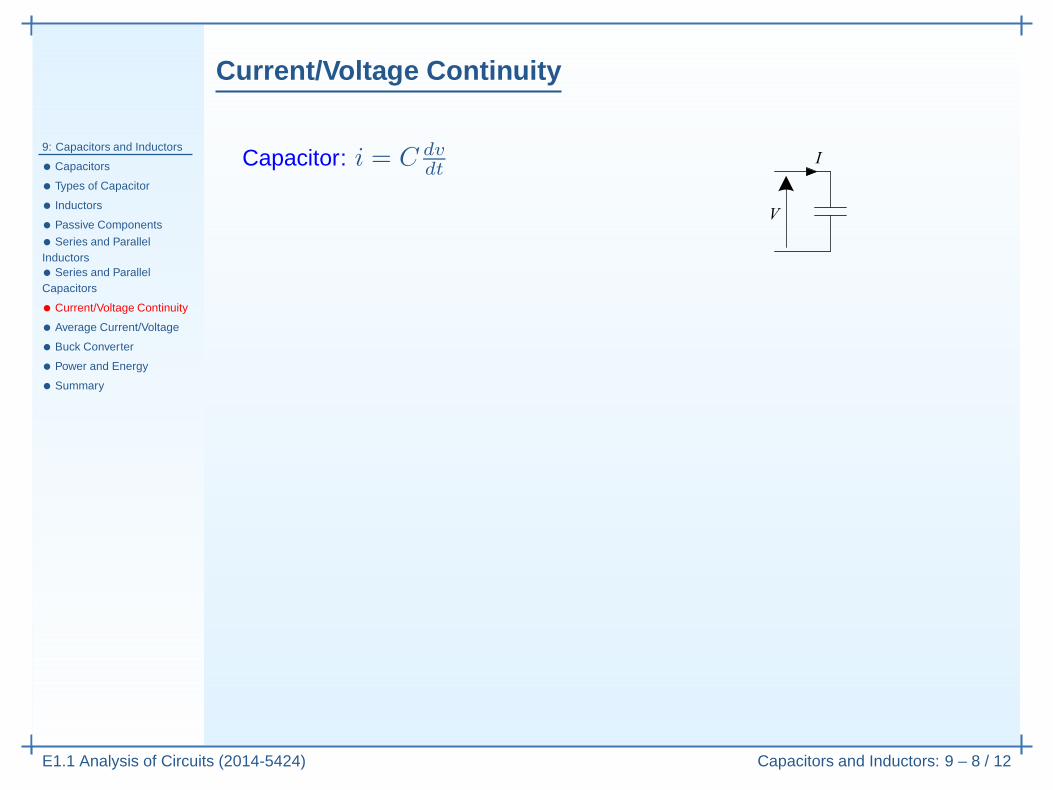
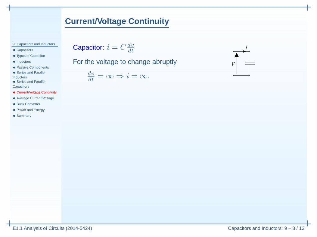
Capacitor: i = C dvdt
Current/Voltage Continuity
9: Capacitors and Inductors
• Capacitors
• Types of Capacitor
• Inductors
• Passive Components
• Series and ParallelInductors• Series and ParallelCapacitors
• Current/Voltage Continuity
• Average Current/Voltage
• Buck Converter
• Power and Energy
• Summary
E1.1 Analysis of Circuits (2014-5424) Capacitors and Inductors: 9 – 8 / 12
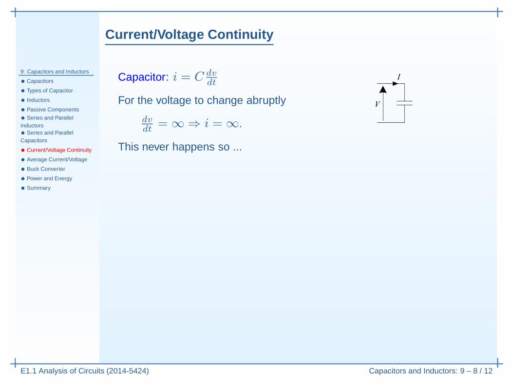
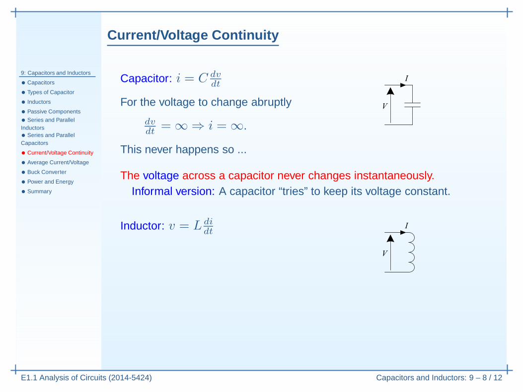
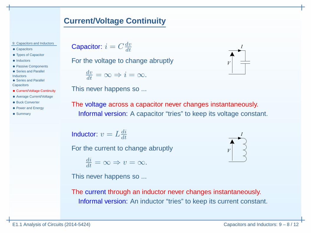
Capacitor: i = C dvdt
For the voltage to change abruptly
dvdt
= ∞ ⇒ i = ∞.
Current/Voltage Continuity
9: Capacitors and Inductors
• Capacitors
• Types of Capacitor
• Inductors
• Passive Components
• Series and ParallelInductors• Series and ParallelCapacitors
• Current/Voltage Continuity
• Average Current/Voltage
• Buck Converter
• Power and Energy
• Summary
E1.1 Analysis of Circuits (2014-5424) Capacitors and Inductors: 9 – 8 / 12
Capacitor: i = C dvdt
For the voltage to change abruptly
dvdt
= ∞ ⇒ i = ∞.
This never happens so ...
Current/Voltage Continuity
9: Capacitors and Inductors
• Capacitors
• Types of Capacitor
• Inductors
• Passive Components
• Series and ParallelInductors• Series and ParallelCapacitors
• Current/Voltage Continuity
• Average Current/Voltage
• Buck Converter
• Power and Energy
• Summary
E1.1 Analysis of Circuits (2014-5424) Capacitors and Inductors: 9 – 8 / 12
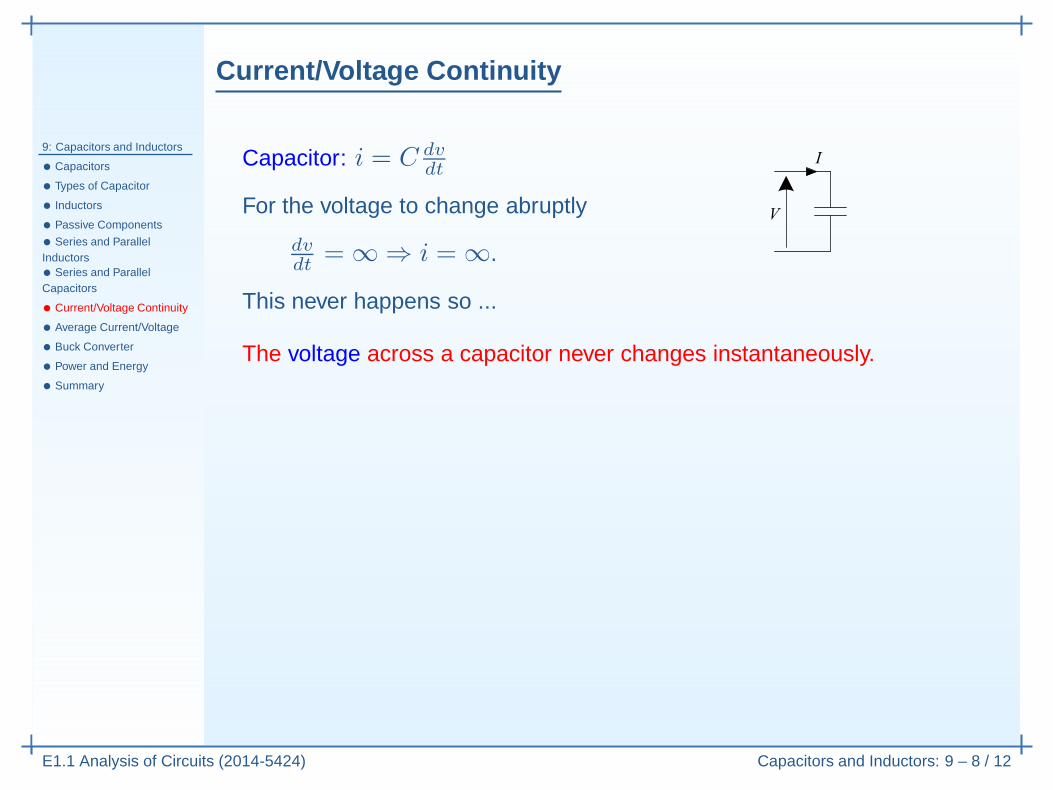
Capacitor: i = C dvdt
For the voltage to change abruptly
dvdt
= ∞ ⇒ i = ∞.
This never happens so ...
The voltage across a capacitor never changes instantaneously.
Current/Voltage Continuity
9: Capacitors and Inductors
• Capacitors
• Types of Capacitor
• Inductors
• Passive Components
• Series and ParallelInductors• Series and ParallelCapacitors
• Current/Voltage Continuity
• Average Current/Voltage
• Buck Converter
• Power and Energy
• Summary
E1.1 Analysis of Circuits (2014-5424) Capacitors and Inductors: 9 – 8 / 12
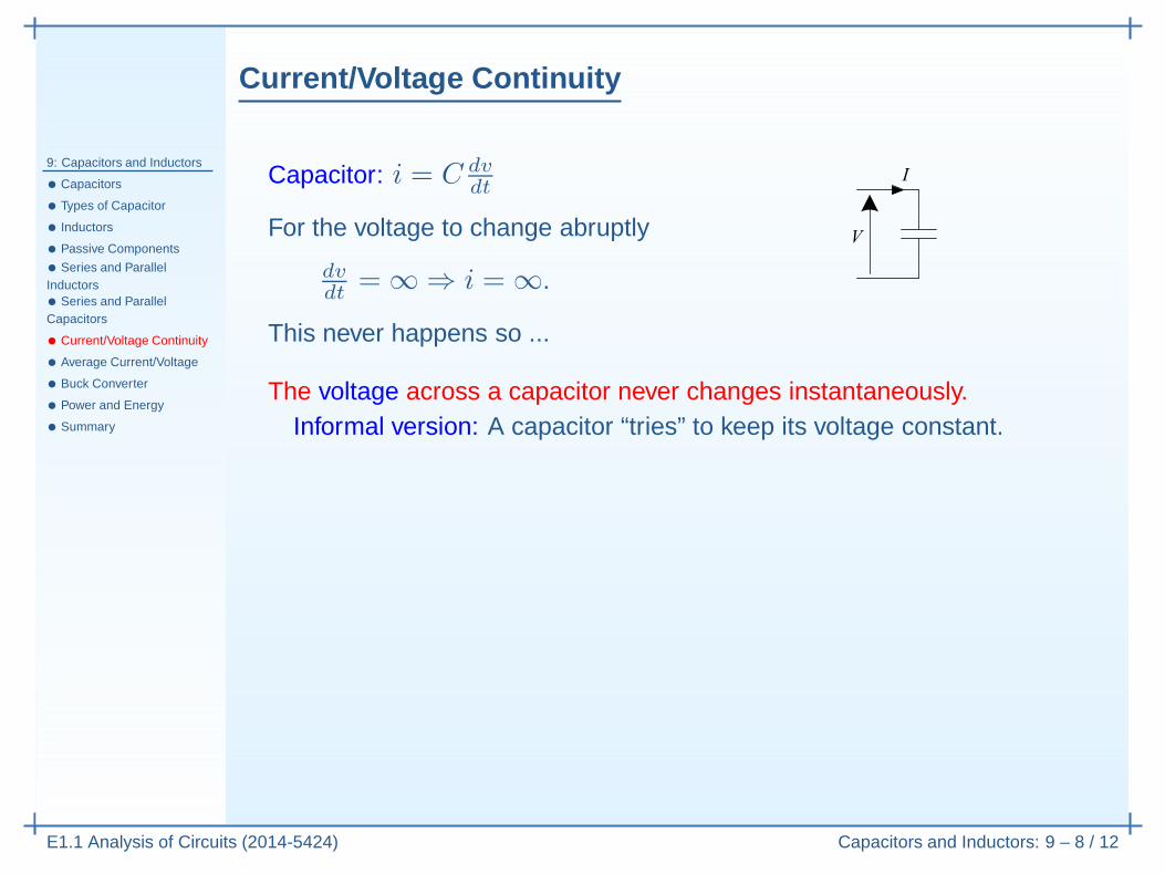
Capacitor: i = C dvdt
For the voltage to change abruptly
dvdt
= ∞ ⇒ i = ∞.
This never happens so ...
The voltage across a capacitor never changes instantaneously.Informal version: A capacitor “tries” to keep its voltage constant.
Current/Voltage Continuity
9: Capacitors and Inductors
• Capacitors
• Types of Capacitor
• Inductors
• Passive Components
• Series and ParallelInductors• Series and ParallelCapacitors
• Current/Voltage Continuity
• Average Current/Voltage
• Buck Converter
• Power and Energy
• Summary
E1.1 Analysis of Circuits (2014-5424) Capacitors and Inductors: 9 – 8 / 12
Capacitor: i = C dvdt
For the voltage to change abruptly
dvdt
= ∞ ⇒ i = ∞.
This never happens so ...
The voltage across a capacitor never changes instantaneously.Informal version: A capacitor “tries” to keep its voltage constant.
Inductor: v = L didt
Current/Voltage Continuity
9: Capacitors and Inductors
• Capacitors
• Types of Capacitor
• Inductors
• Passive Components
• Series and ParallelInductors• Series and ParallelCapacitors
• Current/Voltage Continuity
• Average Current/Voltage
• Buck Converter
• Power and Energy
• Summary
E1.1 Analysis of Circuits (2014-5424) Capacitors and Inductors: 9 – 8 / 12
Capacitor: i = C dvdt
For the voltage to change abruptly
dvdt
= ∞ ⇒ i = ∞.
This never happens so ...
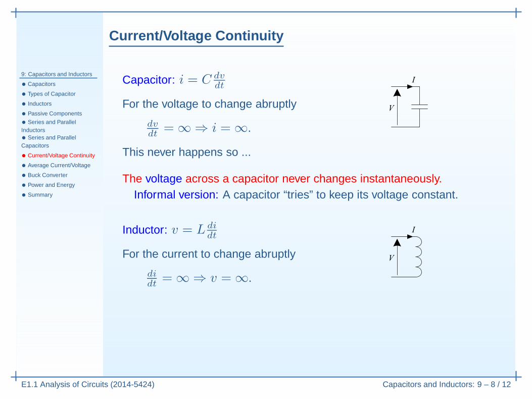
The voltage across a capacitor never changes instantaneously.Informal version: A capacitor “tries” to keep its voltage constant.
Inductor: v = L didt
For the current to change abruptly
didt
= ∞ ⇒ v = ∞.
Current/Voltage Continuity
9: Capacitors and Inductors
• Capacitors
• Types of Capacitor
• Inductors
• Passive Components
• Series and ParallelInductors• Series and ParallelCapacitors
• Current/Voltage Continuity
• Average Current/Voltage
• Buck Converter
• Power and Energy
• Summary
E1.1 Analysis of Circuits (2014-5424) Capacitors and Inductors: 9 – 8 / 12
Capacitor: i = C dvdt
For the voltage to change abruptly
dvdt
= ∞ ⇒ i = ∞.
This never happens so ...
The voltage across a capacitor never changes instantaneously.Informal version: A capacitor “tries” to keep its voltage constant.
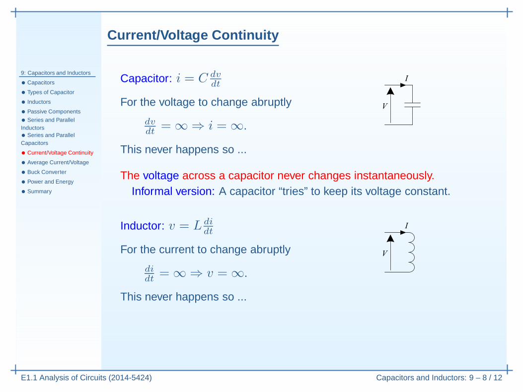
Inductor: v = L didt
For the current to change abruptly
didt
= ∞ ⇒ v = ∞.
This never happens so ...
Current/Voltage Continuity
9: Capacitors and Inductors
• Capacitors
• Types of Capacitor
• Inductors
• Passive Components
• Series and ParallelInductors• Series and ParallelCapacitors
• Current/Voltage Continuity
• Average Current/Voltage
• Buck Converter
• Power and Energy
• Summary
E1.1 Analysis of Circuits (2014-5424) Capacitors and Inductors: 9 – 8 / 12
Capacitor: i = C dvdt
For the voltage to change abruptly
dvdt
= ∞ ⇒ i = ∞.
This never happens so ...
The voltage across a capacitor never changes instantaneously.Informal version: A capacitor “tries” to keep its voltage constant.
Inductor: v = L didt
For the current to change abruptly
didt
= ∞ ⇒ v = ∞.
This never happens so ...
The current through an inductor never changes instantaneously.
Current/Voltage Continuity
9: Capacitors and Inductors
• Capacitors
• Types of Capacitor
• Inductors
• Passive Components
• Series and ParallelInductors• Series and ParallelCapacitors
• Current/Voltage Continuity
• Average Current/Voltage
• Buck Converter
• Power and Energy
• Summary
E1.1 Analysis of Circuits (2014-5424) Capacitors and Inductors: 9 – 8 / 12
Capacitor: i = C dvdt
For the voltage to change abruptly
dvdt
= ∞ ⇒ i = ∞.
This never happens so ...
The voltage across a capacitor never changes instantaneously.Informal version: A capacitor “tries” to keep its voltage constant.
Inductor: v = L didt
For the current to change abruptly
didt
= ∞ ⇒ v = ∞.
This never happens so ...
The current through an inductor never changes instantaneously.Informal version: An inductor “tries” to keep its current constant.
Average Current/Voltage
9: Capacitors and Inductors
• Capacitors
• Types of Capacitor
• Inductors
• Passive Components
• Series and ParallelInductors• Series and ParallelCapacitors
• Current/Voltage Continuity
• Average Current/Voltage
• Buck Converter
• Power and Energy
• Summary
E1.1 Analysis of Circuits (2014-5424) Capacitors and Inductors: 9 – 9 / 12
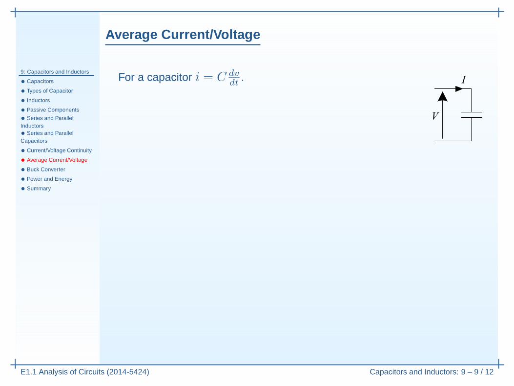
For a capacitor i = C dvdt
.
Average Current/Voltage
9: Capacitors and Inductors
• Capacitors
• Types of Capacitor
• Inductors
• Passive Components
• Series and ParallelInductors• Series and ParallelCapacitors
• Current/Voltage Continuity
• Average Current/Voltage
• Buck Converter
• Power and Energy
• Summary
E1.1 Analysis of Circuits (2014-5424) Capacitors and Inductors: 9 – 9 / 12
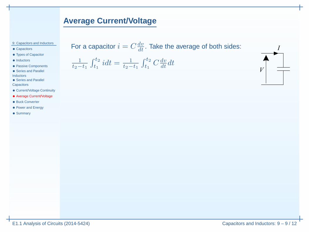
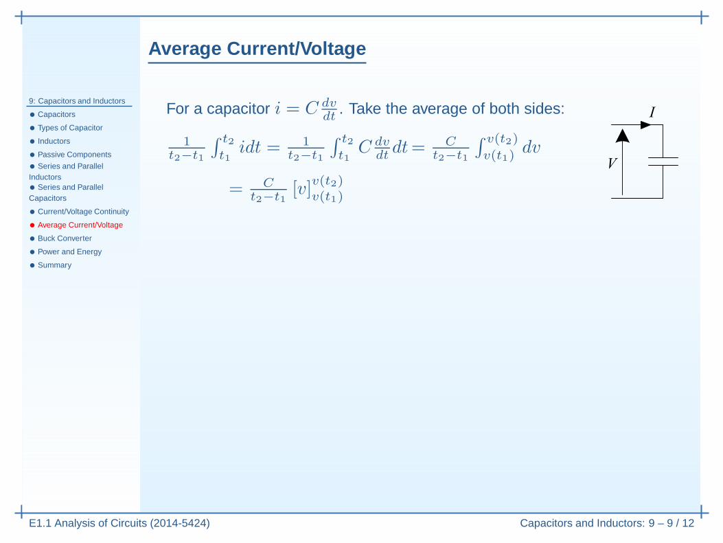
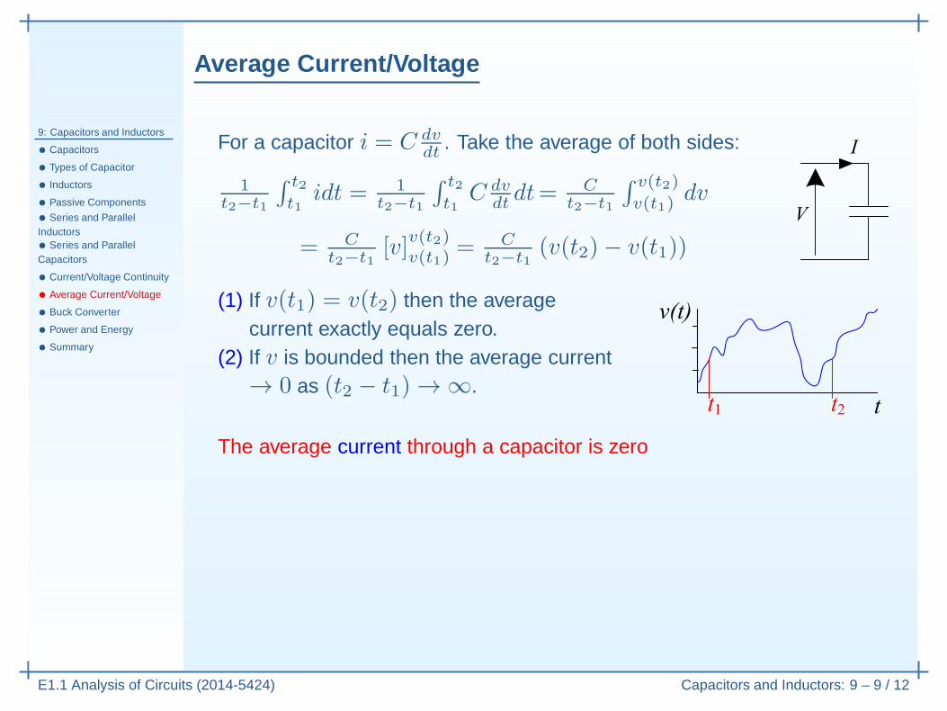
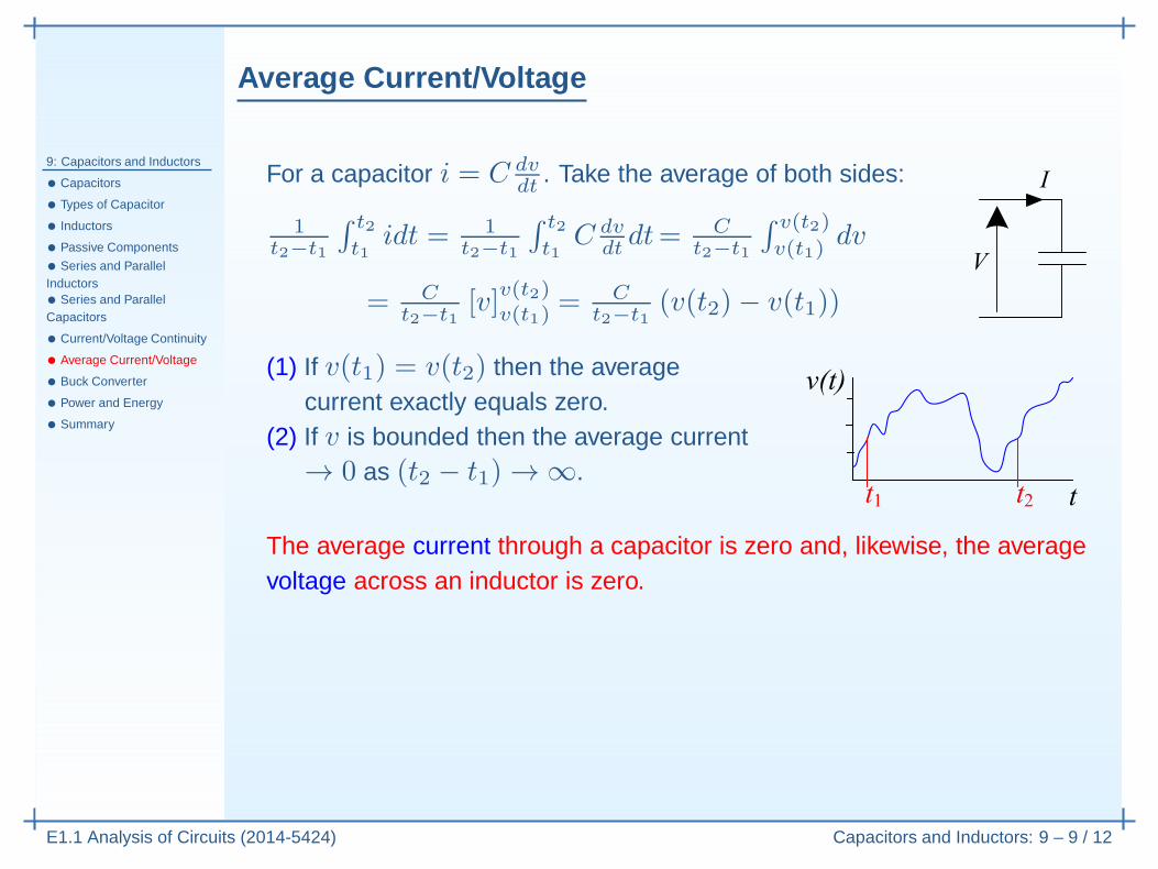
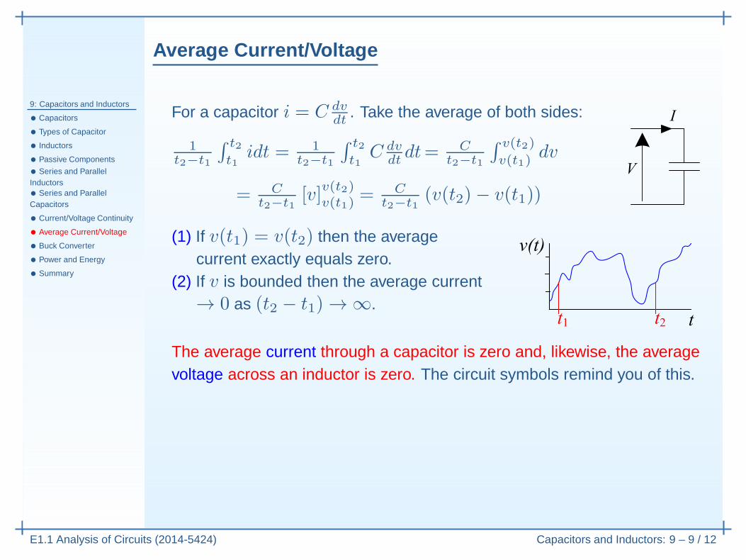
For a capacitor i = C dvdt
. Take the average of both sides:
1t2−t1
∫ t2
t1idt = 1
t2−t1
∫ t2
t1C dv
dtdt
Average Current/Voltage
9: Capacitors and Inductors
• Capacitors
• Types of Capacitor
• Inductors
• Passive Components
• Series and ParallelInductors• Series and ParallelCapacitors
• Current/Voltage Continuity
• Average Current/Voltage
• Buck Converter
• Power and Energy
• Summary
E1.1 Analysis of Circuits (2014-5424) Capacitors and Inductors: 9 – 9 / 12
For a capacitor i = C dvdt
. Take the average of both sides:
1t2−t1
∫ t2
t1idt = 1
t2−t1
∫ t2
t1C dv
dtdt= C
t2−t1
∫ v(t2)
v(t1)dv
= Ct2−t1
[v]v(t2)v(t1)
Average Current/Voltage
9: Capacitors and Inductors
• Capacitors
• Types of Capacitor
• Inductors
• Passive Components
• Series and ParallelInductors• Series and ParallelCapacitors
• Current/Voltage Continuity
• Average Current/Voltage
• Buck Converter
• Power and Energy
• Summary
E1.1 Analysis of Circuits (2014-5424) Capacitors and Inductors: 9 – 9 / 12
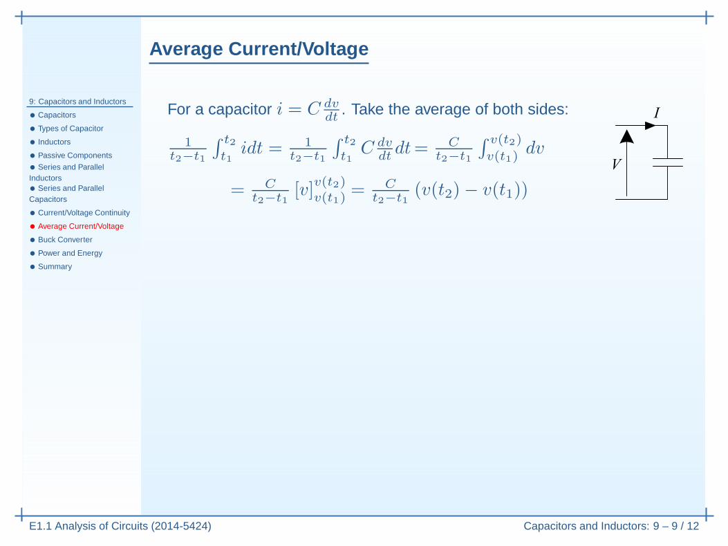
For a capacitor i = C dvdt
. Take the average of both sides:
1t2−t1
∫ t2
t1idt = 1
t2−t1
∫ t2
t1C dv
dtdt= C
t2−t1
∫ v(t2)
v(t1)dv
= Ct2−t1
[v]v(t2)v(t1)
= Ct2−t1
(v(t2)− v(t1))
Average Current/Voltage
9: Capacitors and Inductors
• Capacitors
• Types of Capacitor
• Inductors
• Passive Components
• Series and ParallelInductors• Series and ParallelCapacitors
• Current/Voltage Continuity
• Average Current/Voltage
• Buck Converter
• Power and Energy
• Summary
E1.1 Analysis of Circuits (2014-5424) Capacitors and Inductors: 9 – 9 / 12
For a capacitor i = C dvdt
. Take the average of both sides:
1t2−t1
∫ t2
t1idt = 1
t2−t1
∫ t2
t1C dv
dtdt= C
t2−t1
∫ v(t2)
v(t1)dv
= Ct2−t1
[v]v(t2)v(t1)
= Ct2−t1
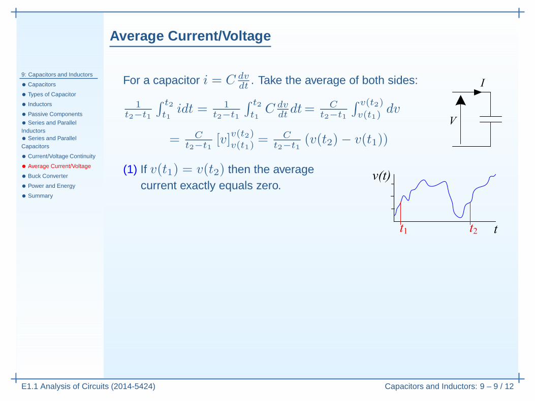
(v(t2)− v(t1))
(1) If v(t1) = v(t2) then the averagecurrent exactly equals zero.
Average Current/Voltage
9: Capacitors and Inductors
• Capacitors
• Types of Capacitor
• Inductors
• Passive Components
• Series and ParallelInductors• Series and ParallelCapacitors
• Current/Voltage Continuity
• Average Current/Voltage
• Buck Converter
• Power and Energy
• Summary
E1.1 Analysis of Circuits (2014-5424) Capacitors and Inductors: 9 – 9 / 12
For a capacitor i = C dvdt
. Take the average of both sides:
1t2−t1
∫ t2
t1idt = 1
t2−t1
∫ t2
t1C dv
dtdt= C
t2−t1
∫ v(t2)
v(t1)dv
= Ct2−t1
[v]v(t2)v(t1)
= Ct2−t1
(v(t2)− v(t1))
(1) If v(t1) = v(t2) then the averagecurrent exactly equals zero.
(2) If v is bounded then the average current→ 0 as (t2 − t1) → ∞.
The average current through a capacitor is zero
Average Current/Voltage
9: Capacitors and Inductors
• Capacitors
• Types of Capacitor
• Inductors
• Passive Components
• Series and ParallelInductors• Series and ParallelCapacitors
• Current/Voltage Continuity
• Average Current/Voltage
• Buck Converter
• Power and Energy
• Summary
E1.1 Analysis of Circuits (2014-5424) Capacitors and Inductors: 9 – 9 / 12
For a capacitor i = C dvdt
. Take the average of both sides:
1t2−t1
∫ t2
t1idt = 1
t2−t1
∫ t2
t1C dv
dtdt= C
t2−t1
∫ v(t2)
v(t1)dv
= Ct2−t1
[v]v(t2)v(t1)
= Ct2−t1
(v(t2)− v(t1))
(1) If v(t1) = v(t2) then the averagecurrent exactly equals zero.
(2) If v is bounded then the average current→ 0 as (t2 − t1) → ∞.
The average current through a capacitor is zero and, likewise, the averagevoltage across an inductor is zero.
Average Current/Voltage
9: Capacitors and Inductors
• Capacitors
• Types of Capacitor
• Inductors
• Passive Components
• Series and ParallelInductors• Series and ParallelCapacitors
• Current/Voltage Continuity
• Average Current/Voltage
• Buck Converter
• Power and Energy
• Summary
E1.1 Analysis of Circuits (2014-5424) Capacitors and Inductors: 9 – 9 / 12
For a capacitor i = C dvdt
. Take the average of both sides:
1t2−t1
∫ t2
t1idt = 1
t2−t1
∫ t2
t1C dv
dtdt= C
t2−t1
∫ v(t2)
v(t1)dv
= Ct2−t1
[v]v(t2)v(t1)
= Ct2−t1
(v(t2)− v(t1))
(1) If v(t1) = v(t2) then the averagecurrent exactly equals zero.
(2) If v is bounded then the average current→ 0 as (t2 − t1) → ∞.
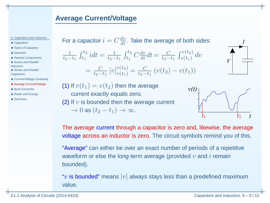
The average current through a capacitor is zero and, likewise, the averagevoltage across an inductor is zero. The circuit symbols remind you of this.
Average Current/Voltage
9: Capacitors and Inductors
• Capacitors
• Types of Capacitor
• Inductors
• Passive Components
• Series and ParallelInductors• Series and ParallelCapacitors
• Current/Voltage Continuity
• Average Current/Voltage
• Buck Converter
• Power and Energy
• Summary
E1.1 Analysis of Circuits (2014-5424) Capacitors and Inductors: 9 – 9 / 12
For a capacitor i = C dvdt
. Take the average of both sides:
1t2−t1
∫ t2
t1idt = 1
t2−t1
∫ t2
t1C dv
dtdt= C
t2−t1
∫ v(t2)
v(t1)dv
= Ct2−t1
[v]v(t2)v(t1)
= Ct2−t1
(v(t2)− v(t1))
(1) If v(t1) = v(t2) then the averagecurrent exactly equals zero.
(2) If v is bounded then the average current→ 0 as (t2 − t1) → ∞.
The average current through a capacitor is zero and, likewise, the averagevoltage across an inductor is zero. The circuit symbols remind you of this.
“Average” can either be over an exact number of periods of a repetitivewaveform or else the long-term average (provided v and i remainbounded).
“v is bounded” means |v| always stays less than a predefined maximumvalue.
Buck Converter
9: Capacitors and Inductors
• Capacitors
• Types of Capacitor
• Inductors
• Passive Components
• Series and ParallelInductors• Series and ParallelCapacitors
• Current/Voltage Continuity
• Average Current/Voltage
• Buck Converter
• Power and Energy
• Summary
E1.1 Analysis of Circuits (2014-5424) Capacitors and Inductors: 9 – 10 / 12
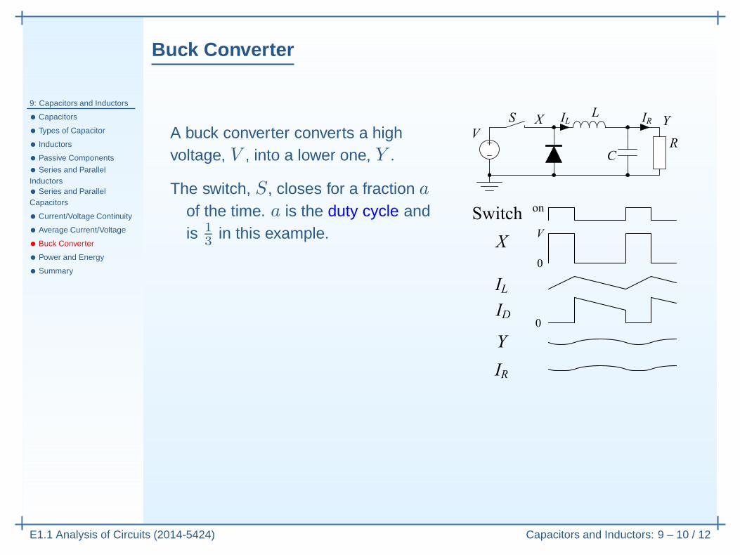
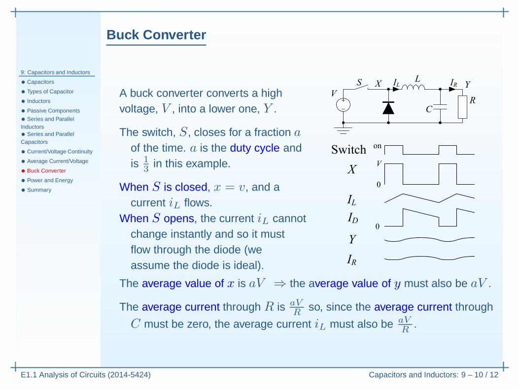
A buck converter converts a highvoltage, V , into a lower one, Y .
The switch, S, closes for a fraction aof the time. a is the duty cycle andis 1
3 in this example.
Buck Converter
9: Capacitors and Inductors
• Capacitors
• Types of Capacitor
• Inductors
• Passive Components
• Series and ParallelInductors• Series and ParallelCapacitors
• Current/Voltage Continuity
• Average Current/Voltage
• Buck Converter
• Power and Energy
• Summary
E1.1 Analysis of Circuits (2014-5424) Capacitors and Inductors: 9 – 10 / 12
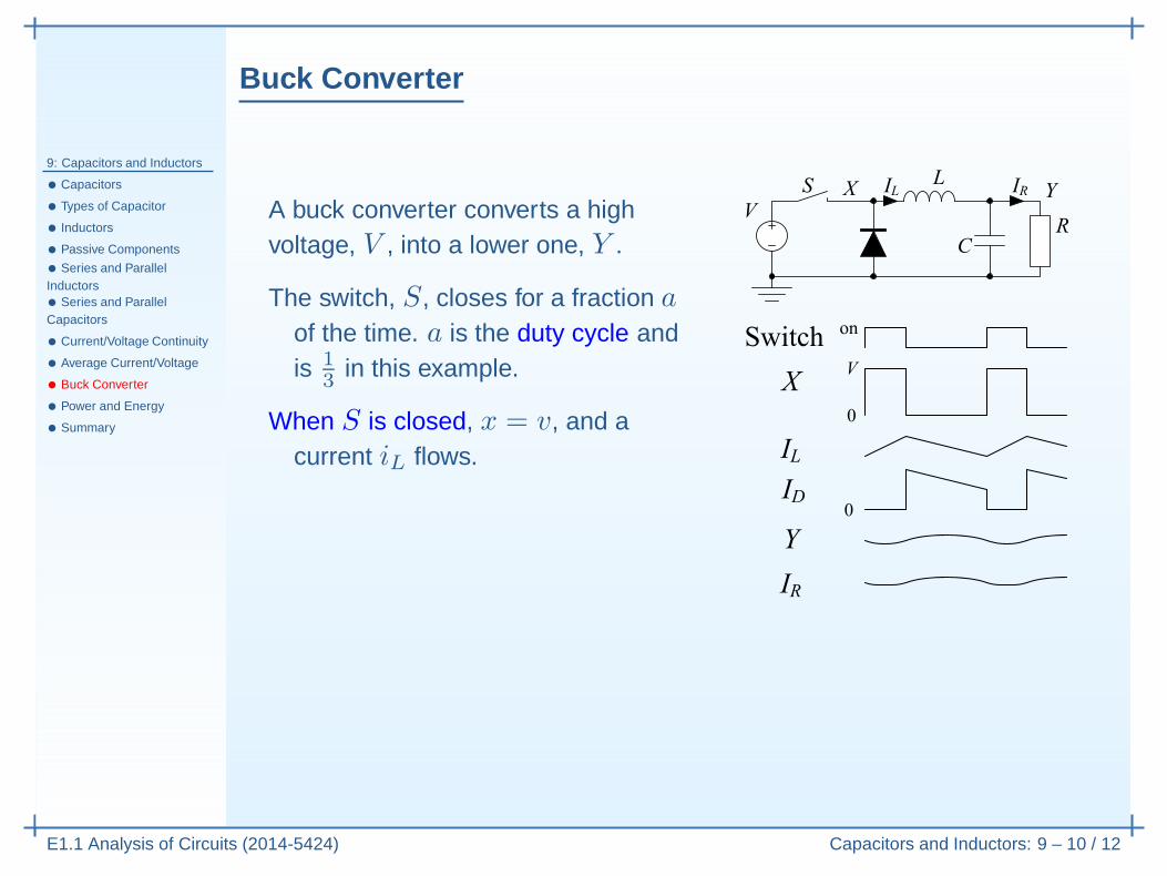
A buck converter converts a highvoltage, V , into a lower one, Y .
The switch, S, closes for a fraction aof the time. a is the duty cycle andis 1
3 in this example.
When S is closed, x = v, and acurrent iL flows.
Buck Converter
9: Capacitors and Inductors
• Capacitors
• Types of Capacitor
• Inductors
• Passive Components
• Series and ParallelInductors• Series and ParallelCapacitors
• Current/Voltage Continuity
• Average Current/Voltage
• Buck Converter
• Power and Energy
• Summary
E1.1 Analysis of Circuits (2014-5424) Capacitors and Inductors: 9 – 10 / 12
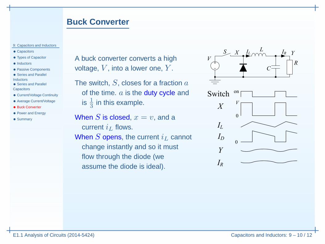
A buck converter converts a highvoltage, V , into a lower one, Y .
The switch, S, closes for a fraction aof the time. a is the duty cycle andis 1
3 in this example.
When S is closed, x = v, and acurrent iL flows.
When S opens, the current iL cannotchange instantly and so it mustflow through the diode (weassume the diode is ideal).
Buck Converter
9: Capacitors and Inductors
• Capacitors
• Types of Capacitor
• Inductors
• Passive Components
• Series and ParallelInductors• Series and ParallelCapacitors
• Current/Voltage Continuity
• Average Current/Voltage
• Buck Converter
• Power and Energy
• Summary
E1.1 Analysis of Circuits (2014-5424) Capacitors and Inductors: 9 – 10 / 12
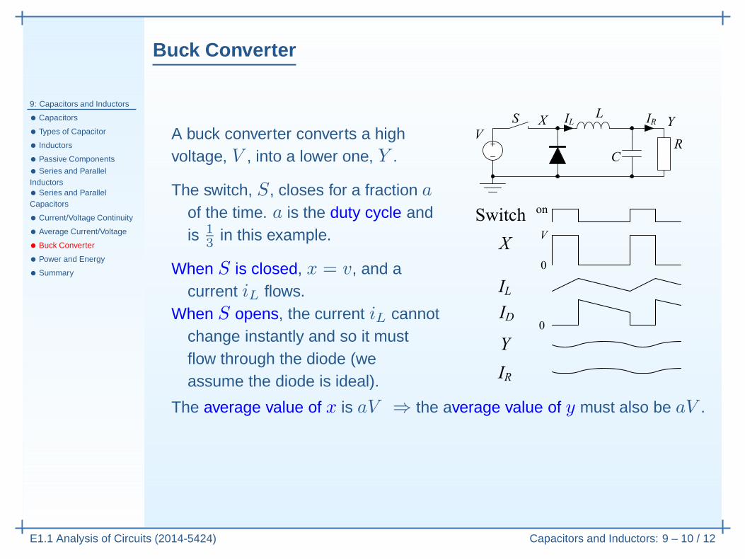
A buck converter converts a highvoltage, V , into a lower one, Y .
The switch, S, closes for a fraction aof the time. a is the duty cycle andis 1
3 in this example.
When S is closed, x = v, and acurrent iL flows.
When S opens, the current iL cannotchange instantly and so it mustflow through the diode (weassume the diode is ideal).
The average value of x is aV ⇒ the average value of y must also be aV .
Buck Converter
9: Capacitors and Inductors
• Capacitors
• Types of Capacitor
• Inductors
• Passive Components
• Series and ParallelInductors• Series and ParallelCapacitors
• Current/Voltage Continuity
• Average Current/Voltage
• Buck Converter
• Power and Energy
• Summary
E1.1 Analysis of Circuits (2014-5424) Capacitors and Inductors: 9 – 10 / 12
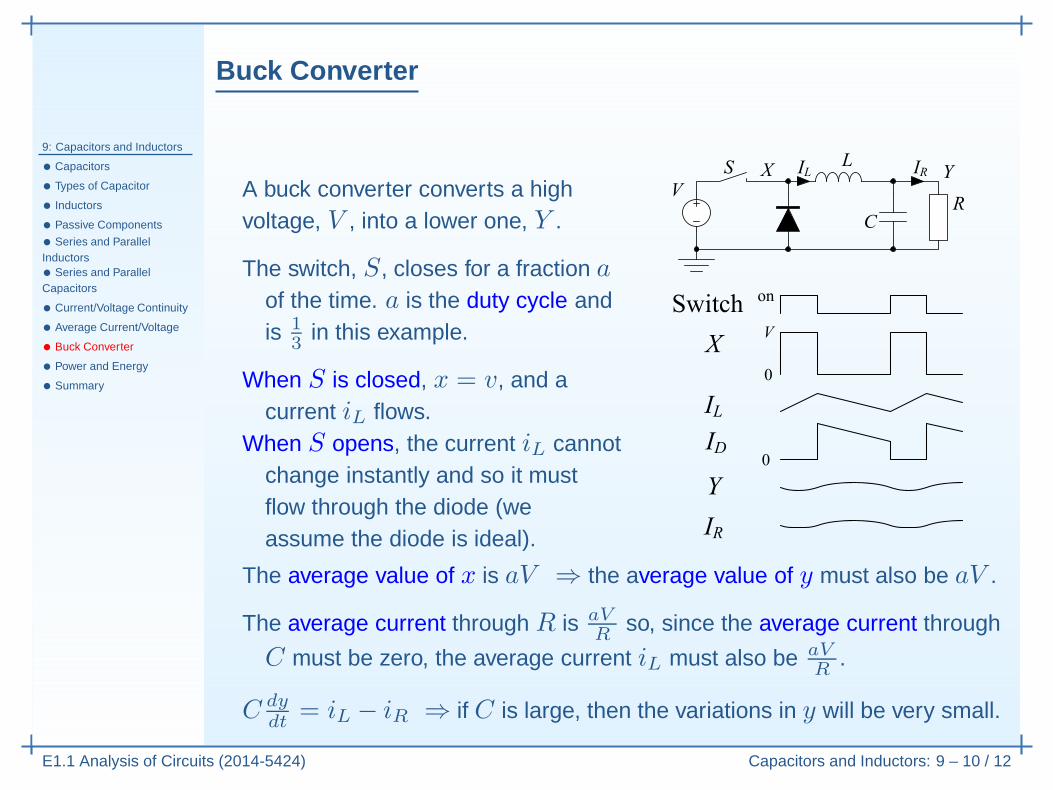
A buck converter converts a highvoltage, V , into a lower one, Y .
The switch, S, closes for a fraction aof the time. a is the duty cycle andis 1
3 in this example.
When S is closed, x = v, and acurrent iL flows.
When S opens, the current iL cannotchange instantly and so it mustflow through the diode (weassume the diode is ideal).
The average value of x is aV ⇒ the average value of y must also be aV .
The average current through R is aVR
so, since the average current through
C must be zero, the average current iL must also be aVR
.
Buck Converter
9: Capacitors and Inductors
• Capacitors
• Types of Capacitor
• Inductors
• Passive Components
• Series and ParallelInductors• Series and ParallelCapacitors
• Current/Voltage Continuity
• Average Current/Voltage
• Buck Converter
• Power and Energy
• Summary
E1.1 Analysis of Circuits (2014-5424) Capacitors and Inductors: 9 – 10 / 12
A buck converter converts a highvoltage, V , into a lower one, Y .
The switch, S, closes for a fraction aof the time. a is the duty cycle andis 1
3 in this example.
When S is closed, x = v, and acurrent iL flows.
When S opens, the current iL cannotchange instantly and so it mustflow through the diode (weassume the diode is ideal).
The average value of x is aV ⇒ the average value of y must also be aV .
The average current through R is aVR
so, since the average current through
C must be zero, the average current iL must also be aVR
.
C dydt
= iL − iR ⇒ if C is large, then the variations in y will be very small.
Buck Converter
9: Capacitors and Inductors
• Capacitors
• Types of Capacitor
• Inductors
• Passive Components
• Series and ParallelInductors• Series and ParallelCapacitors
• Current/Voltage Continuity
• Average Current/Voltage
• Buck Converter
• Power and Energy
• Summary
E1.1 Analysis of Circuits (2014-5424) Capacitors and Inductors: 9 – 10 / 12
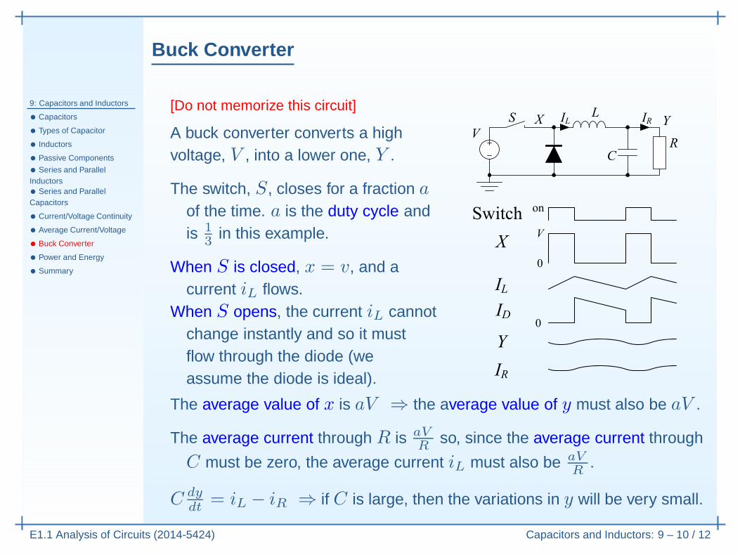
[Do not memorize this circuit]
A buck converter converts a highvoltage, V , into a lower one, Y .
The switch, S, closes for a fraction aof the time. a is the duty cycle andis 1
3 in this example.
When S is closed, x = v, and acurrent iL flows.
When S opens, the current iL cannotchange instantly and so it mustflow through the diode (weassume the diode is ideal).
The average value of x is aV ⇒ the average value of y must also be aV .
The average current through R is aVR
so, since the average current through
C must be zero, the average current iL must also be aVR
.
C dydt
= iL − iR ⇒ if C is large, then the variations in y will be very small.
Power and Energy
9: Capacitors and Inductors
• Capacitors
• Types of Capacitor
• Inductors
• Passive Components
• Series and ParallelInductors• Series and ParallelCapacitors
• Current/Voltage Continuity
• Average Current/Voltage
• Buck Converter
• Power and Energy
• Summary
E1.1 Analysis of Circuits (2014-5424) Capacitors and Inductors: 9 – 11 / 12
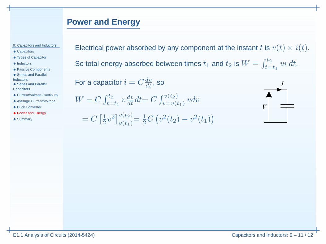
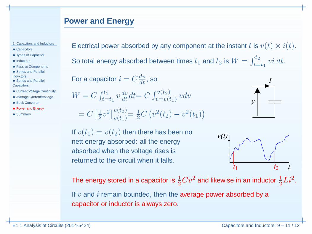
Electrical power absorbed by any component at the instant t is v(t)× i(t).
Power and Energy
9: Capacitors and Inductors
• Capacitors
• Types of Capacitor
• Inductors
• Passive Components
• Series and ParallelInductors• Series and ParallelCapacitors
• Current/Voltage Continuity
• Average Current/Voltage
• Buck Converter
• Power and Energy
• Summary
E1.1 Analysis of Circuits (2014-5424) Capacitors and Inductors: 9 – 11 / 12
Electrical power absorbed by any component at the instant t is v(t)× i(t).
So total energy absorbed between times t1 and t2 is W =∫ t2
t=t1vi dt.
Power and Energy
9: Capacitors and Inductors
• Capacitors
• Types of Capacitor
• Inductors
• Passive Components
• Series and ParallelInductors• Series and ParallelCapacitors
• Current/Voltage Continuity
• Average Current/Voltage
• Buck Converter
• Power and Energy
• Summary
E1.1 Analysis of Circuits (2014-5424) Capacitors and Inductors: 9 – 11 / 12
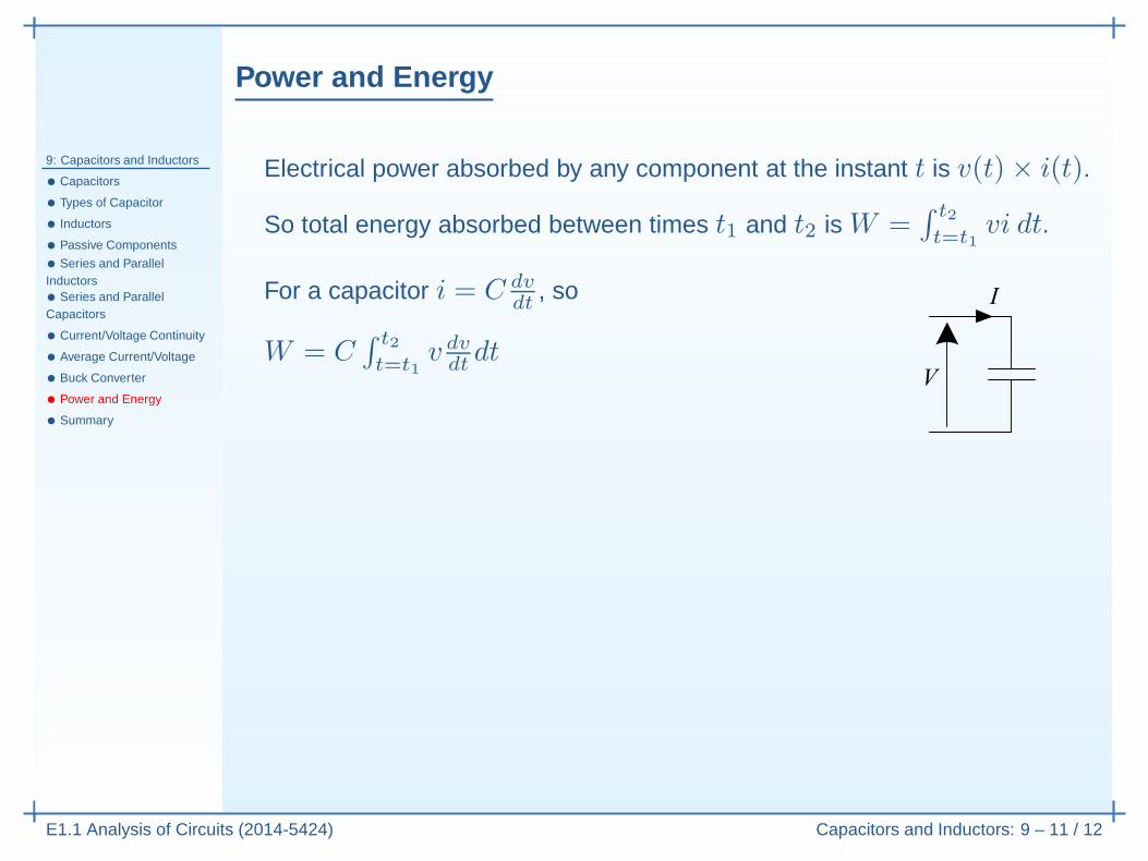
Electrical power absorbed by any component at the instant t is v(t)× i(t).
So total energy absorbed between times t1 and t2 is W =∫ t2
t=t1vi dt.
For a capacitor i = C dvdt
, so
W = C∫ t2
t=t1v dvdtdt
Power and Energy
9: Capacitors and Inductors
• Capacitors
• Types of Capacitor
• Inductors
• Passive Components
• Series and ParallelInductors• Series and ParallelCapacitors
• Current/Voltage Continuity
• Average Current/Voltage
• Buck Converter
• Power and Energy
• Summary
E1.1 Analysis of Circuits (2014-5424) Capacitors and Inductors: 9 – 11 / 12
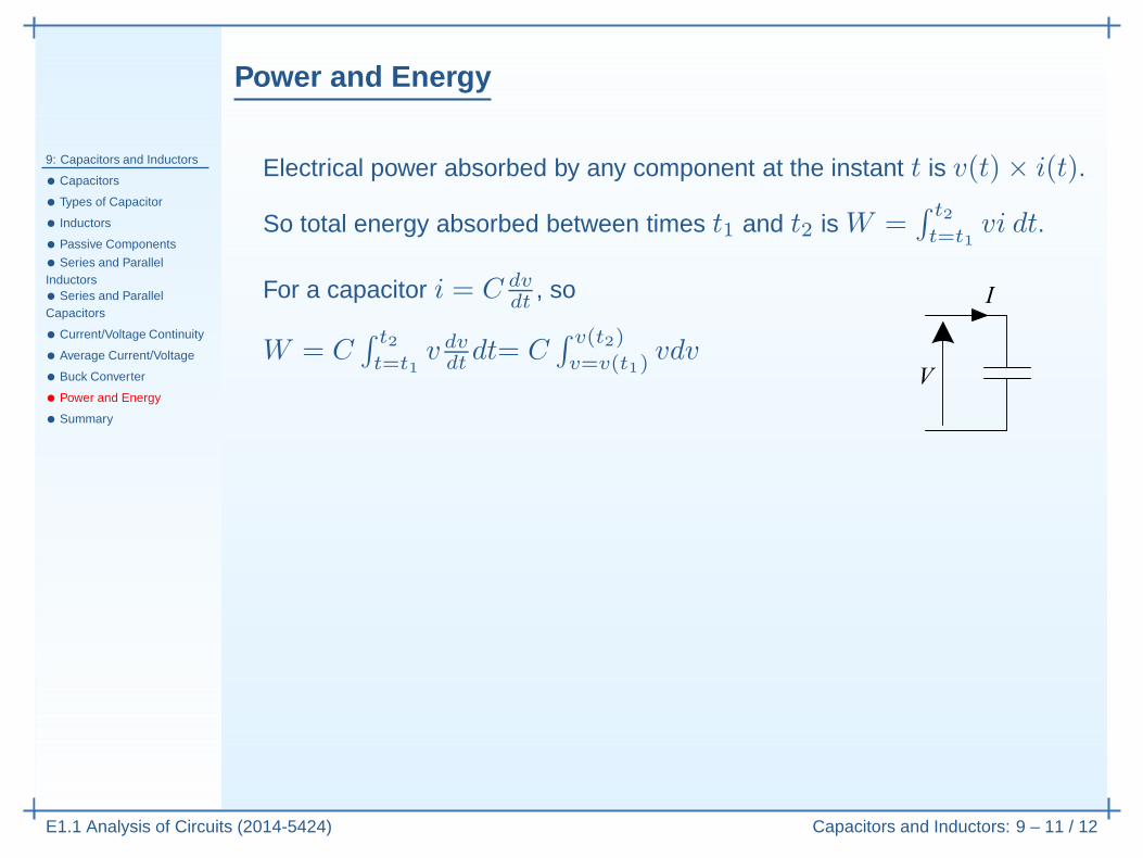
Electrical power absorbed by any component at the instant t is v(t)× i(t).
So total energy absorbed between times t1 and t2 is W =∫ t2
t=t1vi dt.
For a capacitor i = C dvdt
, so
W = C∫ t2
t=t1v dvdtdt= C
∫ v(t2)
v=v(t1)vdv
Power and Energy
9: Capacitors and Inductors
• Capacitors
• Types of Capacitor
• Inductors
• Passive Components
• Series and ParallelInductors• Series and ParallelCapacitors
• Current/Voltage Continuity
• Average Current/Voltage
• Buck Converter
• Power and Energy
• Summary
E1.1 Analysis of Circuits (2014-5424) Capacitors and Inductors: 9 – 11 / 12
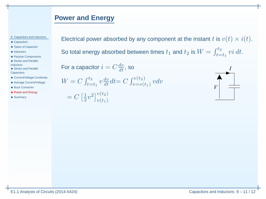
Electrical power absorbed by any component at the instant t is v(t)× i(t).
So total energy absorbed between times t1 and t2 is W =∫ t2
t=t1vi dt.
For a capacitor i = C dvdt
, so
W = C∫ t2
t=t1v dvdtdt= C
∫ v(t2)
v=v(t1)vdv
= C[
12v
2]v(t2)
v(t1)
Power and Energy
9: Capacitors and Inductors
• Capacitors
• Types of Capacitor
• Inductors
• Passive Components
• Series and ParallelInductors• Series and ParallelCapacitors
• Current/Voltage Continuity
• Average Current/Voltage
• Buck Converter
• Power and Energy
• Summary
E1.1 Analysis of Circuits (2014-5424) Capacitors and Inductors: 9 – 11 / 12
Electrical power absorbed by any component at the instant t is v(t)× i(t).
So total energy absorbed between times t1 and t2 is W =∫ t2
t=t1vi dt.
For a capacitor i = C dvdt
, so
W = C∫ t2
t=t1v dvdtdt= C
∫ v(t2)
v=v(t1)vdv
= C[
12v
2]v(t2)
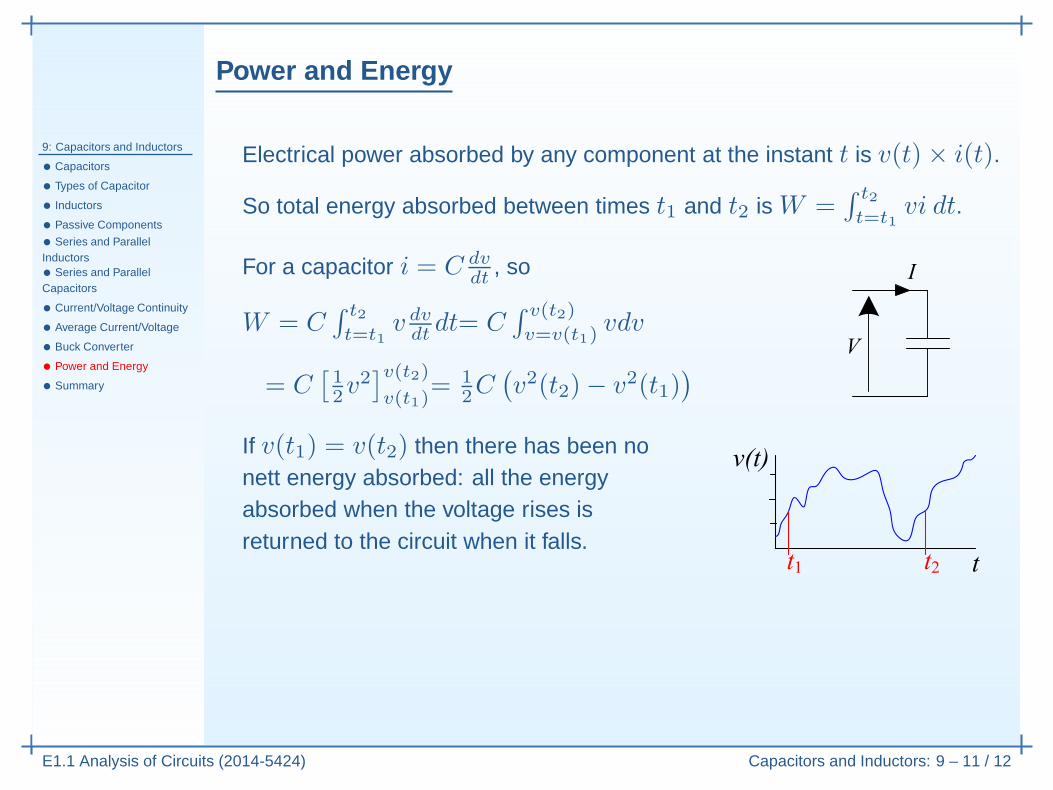
v(t1)= 1
2C(
v2(t2)− v2(t1))
Power and Energy
9: Capacitors and Inductors
• Capacitors
• Types of Capacitor
• Inductors
• Passive Components
• Series and ParallelInductors• Series and ParallelCapacitors
• Current/Voltage Continuity
• Average Current/Voltage
• Buck Converter
• Power and Energy
• Summary
E1.1 Analysis of Circuits (2014-5424) Capacitors and Inductors: 9 – 11 / 12
Electrical power absorbed by any component at the instant t is v(t)× i(t).
So total energy absorbed between times t1 and t2 is W =∫ t2
t=t1vi dt.
For a capacitor i = C dvdt
, so
W = C∫ t2
t=t1v dvdtdt= C
∫ v(t2)
v=v(t1)vdv
= C[
12v
2]v(t2)
v(t1)= 1
2C(
v2(t2)− v2(t1))
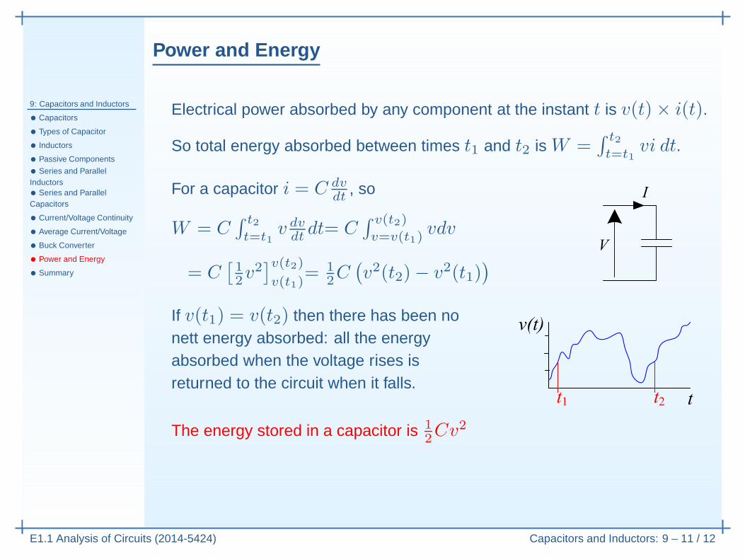
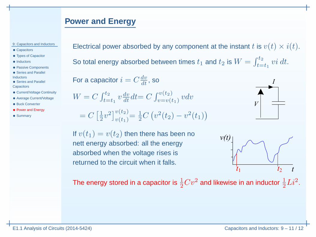
If v(t1) = v(t2) then there has been nonett energy absorbed: all the energyabsorbed when the voltage rises isreturned to the circuit when it falls.
Power and Energy
9: Capacitors and Inductors
• Capacitors
• Types of Capacitor
• Inductors
• Passive Components
• Series and ParallelInductors• Series and ParallelCapacitors
• Current/Voltage Continuity
• Average Current/Voltage
• Buck Converter
• Power and Energy
• Summary
E1.1 Analysis of Circuits (2014-5424) Capacitors and Inductors: 9 – 11 / 12
Electrical power absorbed by any component at the instant t is v(t)× i(t).
So total energy absorbed between times t1 and t2 is W =∫ t2
t=t1vi dt.
For a capacitor i = C dvdt
, so
W = C∫ t2
t=t1v dvdtdt= C
∫ v(t2)
v=v(t1)vdv
= C[
12v
2]v(t2)
v(t1)= 1
2C(
v2(t2)− v2(t1))
If v(t1) = v(t2) then there has been nonett energy absorbed: all the energyabsorbed when the voltage rises isreturned to the circuit when it falls.
The energy stored in a capacitor is 12Cv2
Power and Energy
9: Capacitors and Inductors
• Capacitors
• Types of Capacitor
• Inductors
• Passive Components
• Series and ParallelInductors• Series and ParallelCapacitors
• Current/Voltage Continuity
• Average Current/Voltage
• Buck Converter
• Power and Energy
• Summary
E1.1 Analysis of Circuits (2014-5424) Capacitors and Inductors: 9 – 11 / 12
Electrical power absorbed by any component at the instant t is v(t)× i(t).
So total energy absorbed between times t1 and t2 is W =∫ t2
t=t1vi dt.
For a capacitor i = C dvdt
, so
W = C∫ t2
t=t1v dvdtdt= C
∫ v(t2)
v=v(t1)vdv
= C[
12v
2]v(t2)
v(t1)= 1
2C(
v2(t2)− v2(t1))
If v(t1) = v(t2) then there has been nonett energy absorbed: all the energyabsorbed when the voltage rises isreturned to the circuit when it falls.
The energy stored in a capacitor is 12Cv2 and likewise in an inductor 1
2Li2.
If v and i remain bounded, then the average power absorbed by acapacitor or inductor is always zero.
Summary
9: Capacitors and Inductors
• Capacitors
• Types of Capacitor
• Inductors
• Passive Components
• Series and ParallelInductors• Series and ParallelCapacitors
• Current/Voltage Continuity
• Average Current/Voltage
• Buck Converter
• Power and Energy
• Summary
E1.1 Analysis of Circuits (2014-5424) Capacitors and Inductors: 9 – 12 / 12
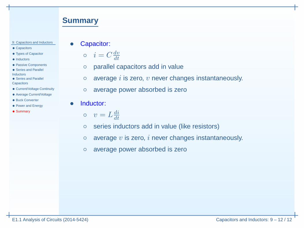
• Capacitor:
◦ i = C dvdt
Summary
9: Capacitors and Inductors
• Capacitors
• Types of Capacitor
• Inductors
• Passive Components
• Series and ParallelInductors• Series and ParallelCapacitors
• Current/Voltage Continuity
• Average Current/Voltage
• Buck Converter
• Power and Energy
• Summary
E1.1 Analysis of Circuits (2014-5424) Capacitors and Inductors: 9 – 12 / 12
• Capacitor:
◦ i = C dvdt
◦ parallel capacitors add in value
◦ average i is zero, v never changes instantaneously.
◦ average power absorbed is zero
• Inductor:
◦ v = L didt
◦ series inductors add in value (like resistors)
◦ average v is zero, i never changes instantaneously.
◦ average power absorbed is zero
Summary
9: Capacitors and Inductors
• Capacitors
• Types of Capacitor
• Inductors
• Passive Components
• Series and ParallelInductors• Series and ParallelCapacitors
• Current/Voltage Continuity
• Average Current/Voltage
• Buck Converter
• Power and Energy
• Summary
E1.1 Analysis of Circuits (2014-5424) Capacitors and Inductors: 9 – 12 / 12
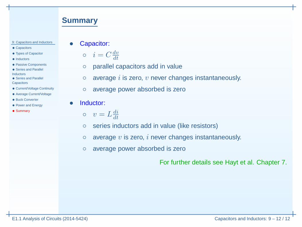
• Capacitor:
◦ i = C dvdt
◦ parallel capacitors add in value
◦ average i is zero, v never changes instantaneously.
◦ average power absorbed is zero
• Inductor:
◦ v = L didt
◦ series inductors add in value (like resistors)
◦ average v is zero, i never changes instantaneously.
◦ average power absorbed is zero
For further details see Hayt et al. Chapter 7.


![Java High Performance Reactive Programmingiproduct.org/.../04/IPT_Reactive_Programming_Java.pdf · Reactive Programming. Functional Programing Reactive Programming [Wikipedia]: a](https://img.pdfslide.us/doc/110x75/5ec60814df097e0643499b13/java-high-performance-reactive-reactive-programming-functional-programing-reactive.jpg)