Embed Size (px)
Citation preview

Operat ing I nst ruc t ions
0070-01-0603-02_revB_Duo ops color.indd 1 3/10/10 5:17:36 PM
Operat ing I nst ruc t ions

0070-10-0603-01 Duo™ Operating Instructions
Duo™ is a U.S. trademark of Mindray DS USA, Inc.
Navigator™ is a U.S. trademark of Mindray DS USA, Inc.
Masimo SET®, LNOP® and CleanShield® are U.S. registered trademarks of Masimo Corp.
Nellcor® and OxiMax® are U.S. registered trademarks of Nellcor Puritan Bennett Inc.
Copyright © Mindray DS USA, Inc., 2008. All rights reserved. Contents of this publication may not be reproduced in any form without permission of Mindray DS USA, Inc.

Table of Contents
Foreword....................................................................................................................................................... iiiWarnings, Precautions And Notes .................................................................................................................... iiiWarnings ...................................................................................................................................................... ivPrecautions .................................................................................................................................................... vNotes ............................................................................................................................................................ viiiIndication for Use ........................................................................................................................................... viiiUnpacking ..................................................................................................................................................... viiiSymbols......................................................................................................................................................... ix
General Product Description.............................................................................................. 1 - 1Overview....................................................................................................................................................... 1 - 1Controls and Indicators.................................................................................................................................... 1 - 2
Front Panel ............................................................................................................................................. 1 - 2Rear Panel .............................................................................................................................................. 1 - 7Bottom Panel........................................................................................................................................... 1 - 8
Operation......................................................................................................................... 2 - 1Modes of Operation........................................................................................................................................ 2 - 1
Normal Monitoring Mode......................................................................................................................... 2 - 1Standby Mode ........................................................................................................................................ 2 - 1Auto Shutoff Mode................................................................................................................................... 2 - 2Maintenance Mode ................................................................................................................................. 2 - 2
Initial Set-Up................................................................................................................................................... 2 - 3Setting the Units of Measure (Units of Measure Mode).................................................................................. 2 - 4
Routine Operation........................................................................................................................................... 2 - 6NIBP Measurement .................................................................................................................................. 2 - 6Pulse Rate Measurement ........................................................................................................................... 2 - 8SpO2 Measurement (Optional).................................................................................................................. 2 - 9
Information Codes and Error Codes .................................................................................................................. 2 - 13Information Codes ................................................................................................................................... 2 - 14Error Codes ............................................................................................................................................ 2 - 16
User Maintenance............................................................................................................. 3 - 1Introduction.................................................................................................................................................... 3 - 1Care and Cleaning of the Monitor .................................................................................................................... 3 - 2Care and Cleaning of Accessories .................................................................................................................... 3 - 2
SpO2 Sensors ......................................................................................................................................... 3 - 2Care and Cleaning of Reusable Cuffs ........................................................................................................ 3 - 3
Battery Replacement and Maintenance .............................................................................................................. 3 - 5Accessories ....................................................................................................................... 4 - 1
Standard Kits.................................................................................................................................................. 4 - 1Optional Accessories ...................................................................................................................................... 4 - 2
NIBP Accessories..................................................................................................................................... 4 - 2SpO2 Accessories.................................................................................................................................... 4 - 3Miscellaneous Accessories........................................................................................................................ 4 - 3
Appendix ......................................................................................................................... 5 - 1Specifications ................................................................................................................................................. 5 - 1
Safety Standards ..................................................................................................................................... 5 - 1Safety Designations ................................................................................................................................. 5 - 2Hazard Analysis (Risk Management).......................................................................................................... 5 - 2Performance/Accuracy ............................................................................................................................ 5 - 2United States Food and Drug Administration Documents............................................................................... 5 - 3
Patient Parameter Specifications ....................................................................................................................... 5 - 4NIBP Sub-System Performance Characteristics ............................................................................................. 5 - 4
Duo™ Operating Instructions 0070-10-0603-01 i

Table of Contents
Systolic Pressure Measurement .................................................................................................................. 5 - 4Diastolic Pressure Measurement................................................................................................................. 5 - 4Static Pressure Measurement ..................................................................................................................... 5 - 4Pulse Rate from NIBP................................................................................................................................ 5 - 5NIBP Sub-System Functional Requirements .................................................................................................. 5 - 5SpO2 Performance Requirements............................................................................................................... 5 - 6Power Supply.......................................................................................................................................... 5 - 10AC Mains Power Source .......................................................................................................................... 5 - 10Battery Power.......................................................................................................................................... 5 - 10Physical Characteristics ............................................................................................................................ 5 - 11Cooling Fan............................................................................................................................................ 5 - 11Environmental and Safety Characteristics.................................................................................................... 5 - 11
Warranty Statements....................................................................................................................................... 5 - 17Manufacturer’s Responsibility ........................................................................................................................... 5 - 19
ii 0070-10-0603-01 Duo™ Operating Instructions

Du
Foreword Introduction
ForewordThe Duo Operating Instructions are intended to provide information for proper operation.
General knowledge of monitoring and an understanding of the features and the functions of the Duo Monitor are prerequisites for proper use.
Do not operate this monitor before reading these instructions.
Information for servicing this instrument is contained in the Duo Monitor Service Manual, (Part Number 0070-00-0604-02). For additional information or assistance, please contact a local authorized representative.
CAUTION: U.S. Federal Law restricts this device to sale by or on the order of a physician or other practitioner licensed by U.S. state law to use or order the use of this device.
Patents: This device is covered under one (1) of more of the following U.S. patents and any foreign equivalents 4,621,643; 4,700,708; 4,770,179; 4,869,254; 4,653,498; 4,928,692; 4,934,372; 5,078,136; 5,482,036; 5,490,505; 5,632,272; 5,685,299; 5,758,644; 5,769,785; 6,157,850; 6,206,830; 4,802,486; 5,351,685; 5,421,329; 5,485,847; 5,533,507; 5,577,500; 5,803,910; 5,853,364; 5,865,736; 6,263,222; 6,083,172 Re. 35,122. Possession or purchase of this device does not convey any express or implied license to use this device with replacement parts which would, alone, or in combination with this device, fall within the scope of one (1) or more of the patents related to this device.
Warnings, Precautions And NotesPlease read and adhere to all warnings, precautions and notes listed here and in the appropriate areas throughout this manual.
A WARNING is provided to alert the user to potential serious outcomes (death, injury, or serious adverse events) to the patient or the user.
A CAUTION is provided to alert the user to use special care necessary for the safe and effective use of the device. They may include actions to be taken to avoid effects on patients or users that may not be potentially life threatening or result in serious injury, but about which the user should be aware. Cautions are also provided to alert the user to adverse effects on this device of use or misuse and the care necessary to avoid such effects.
A NOTE is provided when additional general information is applicable.
o™ Operating Instructions 0070-10-0603-01 iii

Introduction Warnings
iv
WarningsWARNING: The Duo monitor is not intended for unsupervised,
continuous monitoring. It is for spot-check use only.
WARNING: Maintain extreme caution when a defibrillator is in use, avoiding contact with any part of the patient, table or monitor.
WARNING: Route cables neatly. Ensure cables, hoses, and wires are away from patient’s neck to avoid strangulation. Keep floors and walkways free of cables to reduce the risk of tripping.
WARNING: This monitor is not intended for use in an MR environment.
WARNING: The Duo monitor is intended for hospital use under the direct supervision of a licensed health care practitioner.
WARNING: Do not clean the monitor while it is ON and/or connected to AC power.
WARNING: The Duo should not be used adjacent to or stacked with other equipment. If adjacent or stacked use is necessary, the Duo should be observed to verify normal operation in the configuration in which it will be used.
WARNING: Operation of the Duo below the minimum amplitude or value of patient physiological signal may cause inaccurate results.
WARNING: Use of accessories, transducers, and cables other than those specified in the manual may result in increased Electromagnetic Emissions or decreased Electromagnetic Immunity of the Duo. It can also cause delayed recovery after the discharge of a cardiac defibrillator.
WARNING: Do not use a damaged or broken unit or accessory. Periodically, check all cables (e.g., AC line cord and patient connection cables) for damage that may occur through normal use. Replace cable if damaged in any way.
0070-10-0603-01 Duo™ Operating Instructions

Du
Precautions Introduction
PrecautionsCAUTION: Do not place the SpO2 sensor on an extremity with an
invasive catheter or blood pressure cuff in place.
CAUTION: The use of portable and mobile RF communications equipment, in the proximity of the Duo, can affect the performance of this monitor.
CAUTION: Use only Mindray DS accessories with this product. For a comprehensive listing of Duo Accessories refer to section 4.0, “Accessories.”
CAUTION: The patient size selection should be matched to the actual patient before monitoring begins.
CAUTION: Tissue damage or inaccurate measurement may be caused by incorrect SpO2 sensor application or use, such as wrapping too tightly, applying supplemental tape, failing to inspect the sensor site periodically or failing to position appropriately. Carefully read the SpO2 sensor directions and all precautionary information before use.
CAUTION: Excessive ambient light may cause inaccurate SpO2 measurements. In such cases, cover the sensor site with opaque material.
CAUTION: The cuff must be properly applied to the patient's limb before inflating. If it is inflated without being securely wrapped, damage to the cuff can result.
CAUTION: This product contains natural rubber latex which may cause allergic reactions. This refers specifically to the large adult gray blood pressure cuff (0998-00-0003-35).
CAUTION: If the device is accidently saturated with any liquid, immediately discontinue use and contact service personnel.
o™ Operating Instructions 0070-10-0603-01 v

Introduction Precautions
vi
CAUTION: Inaccurate SpO2 measurements may be caused by:
• incorrect sensor application or use
• significant levels of dysfunctional hemoglobins, (e.g., carboxyhemoglobin or methemoglobin)
• intra-vascular dyes such as indocyanine green or methylene blue
• exposure to excessive illumination such as surgical lamps (especially ones with a xenon light source), bilirubin lamps, fluorescent lights, infrared heating lamps, or excessive ambient light. In such cases, cover the sensor site with opaque material.
• excessive patient movement
• venous pulsations
• electro-surgical interference
• placement of a sensor on an extremity that has a blood pressure cuff, arterial catheter or intra-vascular line.
• nail polish or fungus
CAUTION: In certain situations in which perfusion and signal strength are low, such as in patients with thick or pigmented skin, inaccurately low SpO2 readings will result. Verification of oxygenation should be made, especially in patients with chronic lung disease, before instituting any therapy or intervention.
CAUTION: Many patients suffer from poor peripheral perfusion due to hypothermia, hypovolemia, severe vasoconstriction, reduced cardiac output, etc. These symptoms may cause a loss in vital sign readings.
CAUTION: If the SpO2 sensor or patient cable are damaged in any way, discontinue use immediately. To prevent damage, do not soak or immerse the sensor in any liquid solution. Do not attempt to sterilize.
CAUTION: When applying the SpO2 sensor to the patient, ensure proper positioning, alignment and skin integrity. Exercise extreme caution with poorly perfused patients.
CAUTION: When equipped with Masimo SpO2, use only Masimo oxygen sensors and cables. Use of other oxygen sensors may cause improper oximeter performance.
CAUTION: When equipped with Nellcor SpO2, use only Nellcor oxygen sensors and cables. Use of other oxygen sensors may cause improper oximeter performance.
CAUTION: Use only Mindray DS blood pressure cuffs and hoses with the Duo.
0070-10-0603-01 Duo™ Operating Instructions

Du
Precautions Introduction
CAUTION: A patient's skin is sometimes fragile (i.e., on pediatric and geriatric patients, or due to physiological conditions). In these cases, a longer duration between NIBP measurements should be considered to decrease the number of cuff inflations over a period of time. In extreme cases, a thin layer of soft roll or cotton padding may be applied to the limb in order to cushion the skin when the cuff is inflated. This may affect NIBP performance and should be used with caution.
CAUTION: Please consult a physician for interpretation of blood pressure measurements.
CAUTION: A blood pressure measurement can be affected by the position of the patient, and his/her physiological condition as well as other factors, such as patient movement.
CAUTION: Any condition that may affect the regularity and strength of arterial pressures (such as patient movement, cardiac arrhythmias, restriction of hose, etc.), will affect the accuracy and ability to measure the NIBP.
CAUTION: When cleaning SpO2 sensors, do not use an excessive amount of liquid. Wipe the sensor surface with a soft cloth, dampened with a cleaning solution.
CAUTION: Do not subject the SpO2 sensor to autoclaving.
CAUTION: Do not use SpO2 sensors or cables that are damaged or have deteriorated.
CAUTION: Some disinfectants may cause skin irritation. Please rinse the NIBP cuffs thoroughly with water to remove any residual disinfectants.
CAUTION: Using dark colored soaps may stain the NIBP cuffs. Test a single cuff to ensure that no damage will occur.
CAUTION: Disposable NIBP cuffs can be cleaned using a mild soap solution and dried with a clean cloth.
CAUTION: Replace the Lithium Ion battery with part number 0146-00-0079 only.
CAUTION: Remove the battery if the Duo is not likely to be used for an extended period of time.
CAUTION: Remove the battery prior to shipping the Duo.
CAUTION: To avoid permanent damage, do not expose metal components (e.g., pins and sockets) to disinfectants, soaps or chemicals.
CAUTION: Only connect NIBP Luer fittings to Blood Pressure Cuff or Monitor.
o™ Operating Instructions 0070-10-0603-01 vii

Introduction Notes
viii
NotesNOTE: Potential hazards due to errors in software or hardware
have been minimized by actions taken in accordance with IEC 60601-1-4.
NOTE: Information codes and error codes with corresponding explanations are provided to assist in the identification and correction of problems that may occur with the monitor.
NOTE: The comparison testing conducted via the auscultatory method used both Phase 4 and Phase 5 Korotkoff sounds. A report of the study finding for the auscultatory method is available by contacting Technical Support (201) 995-8116.
NOTE: The use of this equipment is restricted to one patient at a time.
Indication for UseThe Duo monitor is intended for use in health care settings under the direct supervision of a licensed health care practitioner. The intended use of the monitor is to monitor physiologic parameter data on adult and pediatric patients. Physiologic data includes: non-invasive blood pressure (NIBP), pulse oximetry and pulse rate as summarized in the operating instructions manual. The information can be displayed only. The monitor is not intended for home use.
UnpackingRemove the instrument and accessories from the shipping cartons and examine them for signs of damage. Check all materials against the packing list. Save the invoice, bill of lading and all packing materials. These may be required to process a claim with the carrier. Contact a Sales Representative or Distributor for assistance in resolving shipping problems.
0070-10-0603-01 Duo™ Operating Instructions

Du
Symbols Introduction
Symbols
SYMBOL DESCRIPTION SYMBOL DESCRIPTION
Attention, Consult Accompanying Documents / Refer to Manual
Type BF Equipment
Dangerous VoltageDefibrillator Proof Type BF Equipment
Equipotentiality Battery Charging
Alternating Current (AC) NIBP
ON/OFF (only for a part of the equipment)
Data Input/Output
Patient Size(Adult/Pediatric)
Clear/Next Patient
Non-ionizing electromagnetic radiation
Consult Operating Instructions
A symbol designating compliance of the Duo monitor with the Medical Device Directive (MDD) 93/42/EEC.
o™ Operating Instructions 0070-10-0603-01 ix

Introduction Symbols
x
This page intentionally left blank.
0070-10-0603-01 Duo™ Operating Instructions

Du
1.0 General Product Description
1.1 OverviewThe Duo is an NIBP spot-check monitor that is intended for use in health care settings on adult and pediatric patients requiring immediate and constant clinical supervision. Its design facilitates rapid, accurate NIBP measurement. The parameters that can be monitored with the Duo are: Non-Invasive Blood Pressure, Pulse Rate and SpO2 (Optional).
The Duo can be powered by an AC connection or rechargeable Lithium Ion battery. Additionally, the unique carrying handle, light weight design and compact size, make Duo extremely portable.
The Duo can be carried by its handle, mounted on a rolling stand, or used as a tabletop device.
NOTE: The Duo can be used in the presence of a defibrillator discharge and during electrosurgery.
NOTE: If it is stored or used outside of the specified environmental conditions, the Duo may not meet performance specifications (see the "Appendix" on page 5-1).
o™ Operating Instructions 0070-10-0603-01 1 - 1

Controls and Indicators General Product Description
1 -
1.2 Controls and Indicators
1.2.1 Front PanelThe Duo front panel is the main user interface, providing the digital LED display, keypad, and connector panel.
FIGURE 1-1 Front Panel
1. Digital Display
The Duo digital display features parameter tiles, numeric LEDs and LED indicators.
SpO2
¨
Source
Sys.
Dia.
SpO2
MAP
C
kPa
NIBP
1
2
3
2 0070-10-0603-01 Duo™ Operating Instructions

Du
General Product Description Controls and Indicators
Parameter Tiles
The parameter tiles (shown in FIGURE 1-2) display the readings for the monitored parameters and also display information codes and error codes. When there is no measurement being determined and no code condition exists for a particular parameter, its associated tile will be blank.
FIGURE 1-2 Parameter Tiles
a. NIBP
• The NIBP parameter tile is separated into three areas that are labeled as: Sys. (systolic), Dia. (diastolic) and MAP (mean arterial pressure). The LEDs are red.
• The labels for the unit of measure are mmHg or kPa.
b. Pulse Rate
• The Pulse Rate parameter tile is labeled with a heart symbol. The LEDs are red.
• The dual source labels are NIBP (red LED) and SpO2 (green LED).
• The label for the unit of measure is bpm.
c. SpO2 (Optional)
• The SpO2 parameter tile is labeled SpO2. The LEDs are green.
• The label for the unit of measure is %.
d. Information Codes
• Information and error codes are displayed in the window.
• See section 2.4.1 for additional information.
a
b
c
d
o™ Operating Instructions 0070-10-0603-01 1 - 3
Controls and Indicators General Product Description
1 -
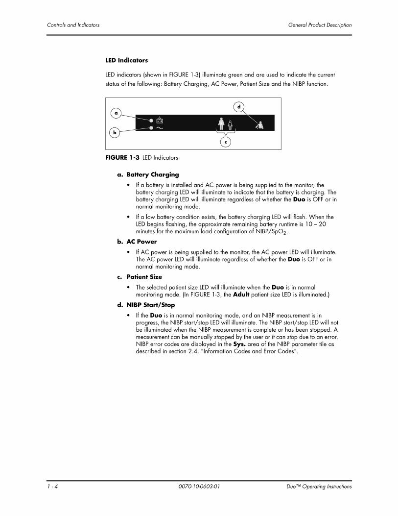
LED Indicators
LED indicators (shown in FIGURE 1-3) illuminate green and are used to indicate the current status of the following: Battery Charging, AC Power, Patient Size and the NIBP function.
FIGURE 1-3 LED Indicators
a. Battery Charging
• If a battery is installed and AC power is being supplied to the monitor, the battery charging LED will illuminate to indicate that the battery is charging. The battery charging LED will illuminate regardless of whether the Duo is OFF or in normal monitoring mode.
• If a low battery condition exists, the battery charging LED will flash. When the LED begins flashing, the approximate remaining battery runtime is 10 – 20 minutes for the maximum load configuration of NIBP/SpO2.
b. AC Power
• If AC power is being supplied to the monitor, the AC power LED will illuminate. The AC power LED will illuminate regardless of whether the Duo is OFF or in normal monitoring mode.
c. Patient Size
• The selected patient size LED will illuminate when the Duo is in normal monitoring mode. (In FIGURE 1-3, the Adult patient size LED is illuminated.)
d. NIBP Start/Stop
• If the Duo is in normal monitoring mode, and an NIBP measurement is in progress, the NIBP start/stop LED will illuminate. The NIBP start/stop LED will not be illuminated when the NIBP measurement is complete or has been stopped. A measurement can be manually stopped by the user or it can stop due to an error. NIBP error codes are displayed in the Sys. area of the NIBP parameter tile as described in section 2.4, “Information Codes and Error Codes”.
a
b
c
d
4 0070-10-0603-01 Duo™ Operating Instructions

Du
General Product Description Controls and Indicators
2. Keypad
The Duo keypad (shown in FIGURE 1-4) is used to initiate all functions. To confirm that a key has been successfully activated, two forms of feedback are provided. Manual feedback is provided in the form of a “click” that can be felt under the fingertip. Audible feedback is provided in the form of a single beep tone when the operation associated with that key is executed.
FIGURE 1-4 Keypad
a. Power ON/OFF
• This key is used to power the Duo ON or OFF. It is also used to exit standby mode and return to normal monitoring mode. The power OFF function features a time delay of two (2) seconds (minimum). When powering the Duo OFF, the user must depress the key for a minimum of 2 seconds.
NOTE: If the Power ON/OFF key is depressed for less than two (2) seconds, the monitor will not power OFF.
• When the Duo is powered OFF, all parameter data is permanently deleted.
b. Clear/Next Patient
• While in normal monitoring mode, this key is used to delete all data (including an NIBP E13 one-time information code) from the current display of the parameter tiles. When the data is deleted, the NIBP cuff inflation pressure is returned to the default value for the selected patient size.
• When a measurement for NIBP is currently in progress, this key is not active.
c. Patient Size
• This key is used to set the patient size to either Adult or Pediatric. While in normal monitoring mode, each press of this key toggles between the two sizes. When the Duo is powered OFF, the current patient size setting is maintained.
• When a measurement for NIBP is in progress, this key is not active.
d. NIBP Start/Stop
• This key is used to start an NIBP measurement and to stop an NIBP measurement that is already in progress.
a
b c
d
o™ Operating Instructions 0070-10-0603-01 1 - 5

Controls and Indicators General Product Description
1 -
3. Connector Panel
FIGURE 1-5 Connector Panel
a. NIBP Pneumatic Fitting
• This Rectus*, Quick-Connect pneumatic fitting is used to attach the NIBP hose to the Duo.
b. SpO2 Receptacle (optional)
• This receptacle is used to attach the SpO2 sensor to the Duo. The two versions of SpO2 technology that are available for use with the DUO are Masimo® and Nellcor®.
* Quick Connect Pneumatic Fittings available from Rectus-TEMA Corporation.
2
ab
6 0070-10-0603-01 Duo™ Operating Instructions
Du
General Product Description Controls and Indicators
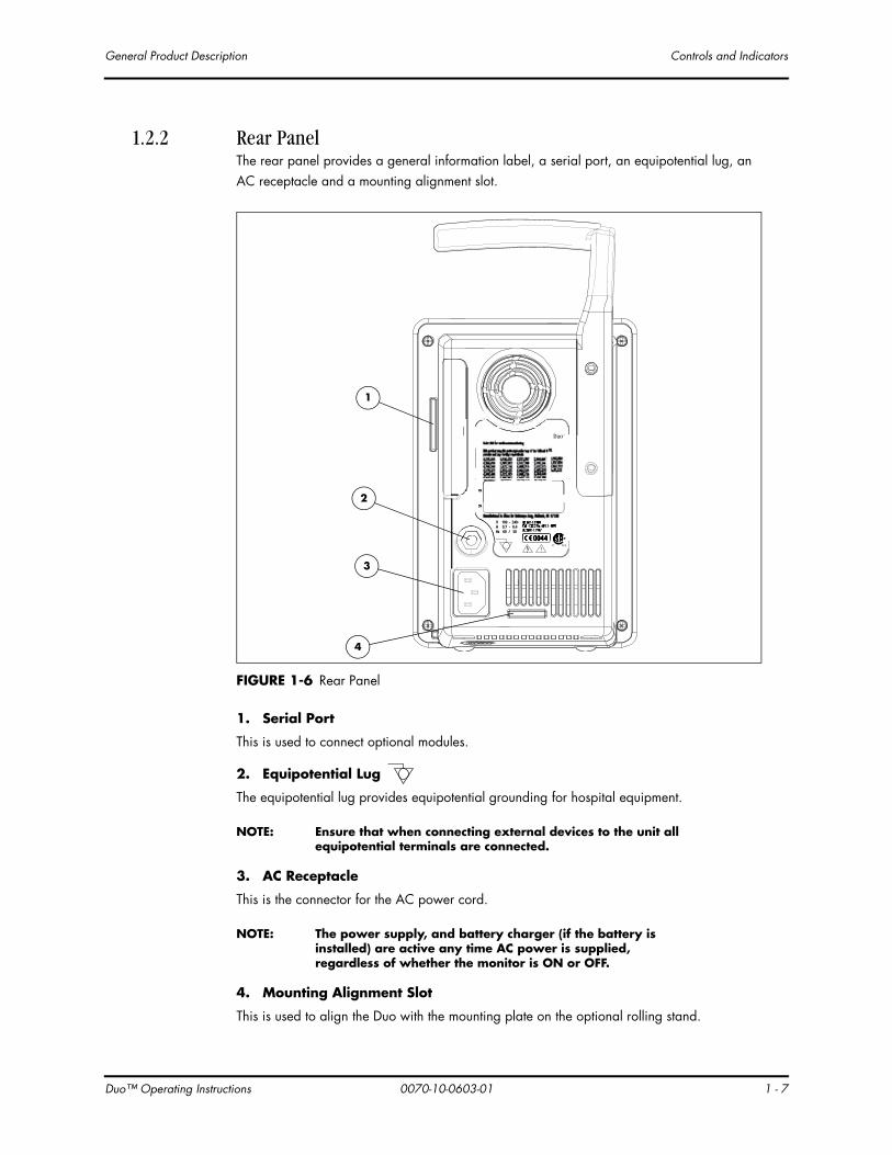
1.2.2 Rear PanelThe rear panel provides a general information label, a serial port, an equipotential lug, an AC receptacle and a mounting alignment slot.
FIGURE 1-6 Rear Panel
1. Serial Port
This is used to connect optional modules.
2. Equipotential Lug
The equipotential lug provides equipotential grounding for hospital equipment.
NOTE: Ensure that when connecting external devices to the unit all equipotential terminals are connected.
3. AC Receptacle
This is the connector for the AC power cord.
NOTE: The power supply, and battery charger (if the battery is installed) are active any time AC power is supplied, regardless of whether the monitor is ON or OFF.
4. Mounting Alignment Slot
This is used to align the Duo with the mounting plate on the optional rolling stand.
IEC 601-1:1988CSA - C22.2 No. 601.1 - M90UL 2601-1:1997
¨0044
V 100 - 240~A 0.7 - 0.4Hz 60 / 50
PN
SN
1
2
3
4
o™ Operating Instructions 0070-10-0603-01 1 - 7

Controls and Indicators General Product Description
1 -
1.2.3 Bottom PanelThe battery compartment and the mounting nut for the optional rolling stand are located on the bottom panel as shown in FIGURE 1-7.
FIGURE 1-7 Bottom Panel
a. Mounting Nut
• The mounting nut secures the Duo to the optional rolling stand.
b. Battery Compartment
• The battery compartment houses one user-replaceable, rechargeable Lithium Ion battery. For ease of use, the door for the battery compartment is tethered to the bottom panel and features a molded finger grip.
a
b
8 0070-10-0603-01 Duo™ Operating Instructions

Du
2.0 Operation
2.1 Modes of OperationThe Duo functions in the following four (4) operating modes:
• Normal Monitoring Mode
• Standby Mode
• Auto Shutoff Mode
• Maintenance Mode
2.1.1 Normal Monitoring ModeThe Normal Monitoring Mode is the mode from which all monitoring functions are initiated during routine operation of the Duo.
2.1.2 Standby ModeThis feature is designed to save power while the Duo is running on battery power. The Duo can only enter Standby Mode from Normal Monitoring Mode and only while it is functioning on battery power. It cannot enter Standby Mode from Maintenance Mode or when it is connected to AC power. Changing the power source from battery to AC while in Standby Mode causes the Duo to automatically return to Normal Monitoring Mode. To indicate that the Duo has entered Standby Mode, the following will occur:
• The number eight (8) will display in the first LED position of the Information Codes tile and will then cycle through each of the three remaining LED positions of that tile.
o™ Operating Instructions 0070-10-0603-01 2 - 1

Modes of Operation Operation
2 -
When any of the events listed in the following table occur, an internal Standby Mode counter is reset to zero and started. The Duo enters Standby Mode after a preset time period for specific events as follows:
In Standby Mode, the only key that is active is Power ON/OFF. When it is pressed for any duration of time, the Duo returns to Normal Monitoring Mode.
NOTE: The Duo cannot be powered OFF while in Standby Mode. It must return to Normal Monitoring Mode before it can be powered OFF.
2.1.3 Auto Shutoff ModeThis feature is also designed to save power while the Duo is operating from the internal battery. When the Duo has been in Standby Mode for 13 minutes, it will automatically power OFF. See the previous subsection for the conditions under which the Duo can enter Standby Mode.
2.1.4 Maintenance ModeMaintenance Mode is a general reference to the following group of non-monitoring modes:
• Unit of Measure Mode
• Version Mode
• NIBP Calibration Mode
• NIBP Pneumatic Test Mode
Of the four (4) modes listed, only Unit of Measure Mode is intended for the clinician and is described in section 2.2.1. The remaining modes are strictly intended for the use of a biomedical technician or other qualified service person. If any of these modes is inadvertently entered, Normal Monitoring Mode can be reestablished by powering OFF and restarting the Duo.
EVENTTIME PERIOD TO ENTER STANDBY MODE
Switching from AC power to battery power 3 minutes
Any key press 3 minutes
The determination of an NIBP value 2 minutes
The acquisition point of SpO2 data 3 minutes
2 0070-10-0603-01 Duo™ Operating Instructions

Du
Operation Initial Set-Up
2.2 Initial Set-UpThis section provides step-by-step instructions for initial set-up of the Duo.
1. Confirm that the proper voltage is available for connecting the Duo to AC power.
2. Install the battery as follows:
• Remove the battery compartment door (shown in FIGURE 2-1).
FIGURE 2-1 Battery Compartment
• The battery compartment is shaped so that the battery can only be inserted in the proper orientation. Disengage the battery locking mechanism by moving its plastic tab away from the center of the compartment (see FIGURE 2-1). Insert the new Lithium Ion battery with its contacts (shown in FIGURE 2-2) facing the rear of the compartment.
FIGURE 2-2 Lithium Ion Battery
• Ensure that the locking mechanism engages over the end of the battery by pressing the battery firmly into the compartment.
• Replace the battery compartment door.
Battery Locking Mechanism
Battery Compartment
Door
Contacts
o™ Operating Instructions 0070-10-0603-01 2 - 3
Initial Set-Up Operation
2 -
NOTE: The Lithium Ion battery is shipped in a partially charged state and must be fully charged prior to its first use.
3. Charge the Lithium Ion battery as follows:
• Connect the AC power cord to the AC receptacle located on the rear panel.
• Plug the opposite end of the AC power cord into the appropriate AC outlet. The Battery Charging indicator will be illuminated on the front panel.
• Allow the battery to charge for a minimum of 4 hours.
NOTE: Optimum battery runtime is achieved after 3 charge/discharge cycles.
4. Power ON the Duo by pressing the Power ON/OFF key. A single beep tone indicates that the Duo has successfully powered ON. An internal diagnostic test and an LED test are then executed. For the duration of the tests, all operational LEDs are displayed and the number “8” (plus any decimal LEDs) is displayed in the parameter tiles. When the tests are successfully complete, the following LEDs remain displayed:
• AC Power indicator (if AC power is present)
• Battery Charging indicator (if the battery is installed and AC power is present)
• Patient Size indicator (the current setting)
• Unit of Measure indicators (the most recent settings) for NIBP, Pulse Rate and SpO2 (optional)
If any portion of the internal diagnostics test fails, error codes are displayed in specific parameter tiles as described in "Information Codes and Error Codes" on page 2-13.
2.2.1 Setting the Units of Measure (Units of Measure Mode)The NIBP parameter has 2 choices for the unit of measure. This setting is maintained after the Duo is powered OFF. The units of measure for Pulse Rate (bpm) and SpO2 (%) are not adjustable.
• The NIBP units of measure are mmHg and kPa.
The default setting is mmHg.
4 0070-10-0603-01 Duo™ Operating Instructions

Du
Operation Initial Set-Up
Use the following procedure to change the units of measure.
1. Ensure that the power to the Duo is OFF.
2. Press and hold the Clear/Next Patient key.
3. While continuing to hold the Clear/Next Patient key, press and hold the Power ON/OFF key for two (2) seconds until the Duo beeps.
4. Release both keys.
5. After an additional 2-second delay, the Duo will light the LED to show the currently stored setting of the NIBP unit of measure.
6. Press the Clear/Next patient key repeatedly until the desired NIBP (mmHg or kPa) unit of measure is showing.
7. Press the Power ON/OFF key for two (2) seconds to turn the Duo off and save the new settings.
8. You may then turn the Duo back on to resume normal operation.
NOTE: The Duo cannot be placed directly back into normal monitoring mode after setting the units of measure. It must first be powered OFF.
o™ Operating Instructions 0070-10-0603-01 2 - 5

Routine Operation Operation
2 -
2.3 Routine OperationThis section provides guidelines and step-by-step instructions for the vital sign measurements that are routinely performed with the Duo.
2.3.1 NIBP Measurement
CAUTION: A patient's skin is sometimes fragile (i.e., on pediatric and geriatric patients, or due to physiological conditions). In these cases, a longer duration between NIBP measurements should be considered to decrease the number of cuff inflations over a period of time. In extreme cases, a thin layer of soft roll or cotton padding may be applied to the limb in order to cushion the skin when the cuff is inflated. This may affect NIBP performance and should be used with caution.
CAUTION: Please consult a physician for interpretation of blood pressure measurements.
CAUTION: A blood pressure measurement can be affected by the position of the patient, and his/her physiological condition as well as other factors, such as patient movement.
CAUTION: Any condition that may affect the regularity and strength of arterial pressures (such as patient movement, cardiac arrhythmias, restriction of hose, etc.), will affect the accuracy and ability to measure the NIBP.
The Duo utilizes the oscillometric method of measuring Non-Invasive Blood Pressure (NIBP). The measurement includes systolic (Sys.), diastolic (Dia.) and mean arterial pressure (MAP). There is no provision for interval measurement. Each measurement must be initiated by pressing the NIBP Start/Stop key while the Duo is in normal monitoring mode.
The initial default cuff inflation pressure is dependent on the patient size setting as follows:
If the Duo is in normal monitoring mode, then the selected NIBP unit of measure LED will be illuminated red, regardless of whether there is an NIBP value being displayed.
Upon power ON of the Duo, the NIBP unit of measure setting defaults to the most recent setting made in the Unit of Measure mode.
During the inflation and bleed portions of the NIBP measurement, the current cuff pressure displays in the MAP section of the NIBP parameter tile and updates approximately once every second.
After the first successful measurement, the subsequent inflation pressure for the same patient will be 50 ±10 mmHg above the previous systolic pressure measurement.
PATIENT SIZE SETTING
DEFAULT CUFF INFLATION PRESSURE
Adult 178 ± 5 mmHg
Pediatric 133 ± 5 mmHg
6 0070-10-0603-01 Duo™ Operating Instructions

Du
Operation Routine Operation
If a measurement cannot be obtained, the Duo automatically reinflates the cuff to 30 – 60 mmHg higher than the initial inflation pressure, but will not exceed the maximum cuff pressure listed in the “NIBP Sub-System Functional Requirements”, section 5.2.6. This process will only repeat three times and then an associated error code will be displayed. Refer to "Information Codes and Error Codes" on page 2-13 for further information.
NOTE: Pressing the Clear/Next Patient key while there are no measurements in progress will reset the NIBP cuff inflation pressure to the default value for the selected patient size.
1. Select a blood pressure cuff that is appropriate for the size of the patient. Measure the circumference of the patient's limb for the best results.
NOTE: Using a correctly sized cuff, among other considerations, has a direct bearing on the accuracy of the obtained NIBP measurements. A cuff that is too narrow for the limb will result in erroneously high readings. Selection of the cuff size should be based on the circumference of the patient’s limb. The design dimensions of the cuffs and their intended use are based on recommendations made by the American Heart Association.
CAUTION: Use only Mindray DS blood pressure cuffs and hoses with the Duo.
2. Attach the NIBP cuff to the NIBP extension hose.
3. Attach the NIBP extension hose to the NIBP pneumatic fitting on the Duo.
4. Apply the cuff to the patient as shown in FIGURE 2-3. Ensure that the cuff is deflated and lies directly against the patient's skin. The cuff should fit snugly. There should be no clothing between the patient’s skin and the cuff.
CAUTION: The cuff must be properly applied to the patient's limb before inflating. If it is inflated without being securely wrapped, damage to the cuff can result.
FIGURE 2-3 Application of the Blood Pressure Cuff
5. Ensure that the appropriate patient size has been selected on the Duo.
6. Press the NIBP Start/Stop key to begin the NIBP measurement.
o™ Operating Instructions 0070-10-0603-01 2 - 7

Routine Operation Operation
2 -
The cuff begins to inflate. After reaching the default pressure for the selected patient size, the cuff slowly deflates and the Duo collects oscillometric pulsations. During this inflation and deflation portion of the measurement, the MAP section of the NIBP parameter tile displays the current pressure in the cuff. During this same period, the Sys. and Dia. sections of the NIBP parameter tile display dashes “- - -”.
The patient should remain still to avoid the introduction of unnecessary motion artifact. After the cuff pressure drops below the diastolic pressure, the measurements are displayed in the NIBP parameter tile. These results will be deleted and the NIBP parameter tile will be blank if one of the following occurs:
• 15 minutes elapse since the last NIBP measurement
• The Clear/Next Patient key is pressed to clear the results
• The Duo is powered OFF
If the Duo enters Standby Mode, the internal counter for the elapsed time since the last NIBP measurement continues. If Normal Monitoring Mode resumes before the counter reaches 15 minutes, the NIBP results will display until one of the previous bulleted items occurs or the Duo again enters Standby Mode.
NOTE: Pressing the NIBP Start/Stop key while the NIBP measurement is in progress will stop the measurement and deflate the cuff.
2.3.2 Pulse Rate MeasurementThe Pulse Rate is determined from one of two sources: SpO2 and NIBP.
NOTE: If the optional SpO2 is not purchased with the Duo, the Pulse Rate source will be NIBP by default.
SpO2 is the higher priority source. If both SpO2 and NIBP are being actively monitored, SpO2 will be the source for the Pulse Rate measurement. If only NIBP is being actively monitored, it will be the source for the Pulse Rate measurement.
• When determined from SpO2, the Pulse Rate updates approximately once every second. When SpO2 is no longer being monitored, the Pulse Rate parameter tile will be blank.
• When determined from NIBP, the Pulse Rate will display until the NIBP results are no longer displayed, as described in section 2.3.1.
NOTE: Pulse Rate from NIBP is a static value since NIBP is a static, one-time measurement.
The Pulse Rate results will display for the same maximum time that the source parameter (SpO2 or NIBP) is displayed.
8 0070-10-0603-01 Duo™ Operating Instructions
Du
Operation Routine Operation
2.3.3 SpO2 Measurement (Optional)Each of the following terms are associated with blood oxygenation: oxygen saturation, pulse oximetry, SpO2 and plethysmography.
Oxygen saturation in capillary blood is measured by a method called pulse oximetry. Pulse oximetry is a continuous and non-invasive measurement of the amount of oxygen attached to the hemoglobin in red blood cells (also known as oxyhemoglobin saturation). SpO2 is the estimation of arterial oxygen saturation. This term is used interchangeably with SaO2. This value is displayed in the SpO2 parameter tile.
Traditional pulse oximetry determines SpO2 by passing red and infrared light into a capillary bed and measuring changes in light absorption during the pulsatile cycle. Red and infrared light-emitting diodes (LEDs) in oximetry sensors serve as the light sources, a photodiode serves as the photo detector.
Traditional pulse oximetry assumes that all pulsations in the light absorbance signal are caused by oscillations in the arterial blood volume. This also assumes that the blood flow in the region of the sensor passes entirely through the capillary bed rather than through any arterio-venous shunts.
Performance ConsiderationsTo ensure optimal SpO2 measurement, use an appropriate sensor, apply it as directed, and observe all warnings and cautions. Sensors are designed for specific sites on patients with designated weight ranges. To select the appropriate sensor, consider the patient’s weight, level of activity, adequacy of perfusion, available sensor sites and the sterility requirement.
If excessive ambient light is present, cover the sensor site with opaque material. Failure to do so may cause inaccurate measurements. Light sources that can affect performance include surgical lights (especially those with a xenon light source), bilirubin lamps, fluorescent lights, infrared heating lamps, and direct sunlight.
In the event that a reading is unobtainable or inaccurate, consider the following:
• If the patient is poorly perfused, try applying the sensor to another site - such as a different finger or toe.
• Ensure that the sensor is properly aligned and securely applied.
• Use a new sensor.
• Move the sensor to a less active site.
• Use a type of sensor that tolerates some patient motion.
• Ensure that the sensor and site are clean/non-greasy. Nail polish andfungus should be removed.
CalibrationThe oximetry sub-system incorporates automatic calibration mechanisms. No other calibration is required.
o™ Operating Instructions 0070-10-0603-01 2 - 9

Routine Operation Operation
2 -
CAUTION: Do not place the SpO2 sensor on an extremity with an invasive catheter or blood pressure cuff in place.
CAUTION: Tissue damage or inaccurate measurement may be caused by incorrect SpO2 sensor application or use, such as wrapping too tightly, applying supplemental tape, failing to inspect the sensor site periodically or failing to position appropriately. Carefully read the SpO2 sensor directions and all precautionary information before use.
CAUTION: Inaccurate SpO2 measurements may be caused by:
• incorrect sensor application or use
• significant levels of dysfunctional hemoglobins, (e.g., carboxyhemoglobin or methemoglobin)
• intra-vascular dyes such as indocyanine green or methylene blue
• exposure to excessive illumination such as surgical lamps (especially ones with a xenon light source), bilirubin lamps, fluorescent lights, infrared heating lamps, or excessive ambient light. In such cases, cover the sensor site with opaque material.
• excessive patient movement
• venous pulsations
• electro-surgical interference
• placement of a sensor on an extremity that has a blood pressure cuff, arterial catheter or intra-vascular line.
• nail polish or fungus
CAUTION: In certain situations in which perfusion and signal strength are low, such as in patients with thick or pigmented skin, inaccurately low SpO2 readings will result. Verification of oxygenation should be made, especially in patients with chronic lung disease, before instituting any therapy or intervention.
CAUTION: Many patients suffer from poor peripheral perfusion due to hypothermia, hypovolemia, severe vasoconstriction, reduced cardiac output, etc. These symptoms may cause a loss in vital sign readings.
CAUTION: If the SpO2 sensor or patient cable are damaged in any way, discontinue use immediately. To prevent damage, do not soak or immerse the sensor in any liquid solution. Do not attempt to sterilize.
CAUTION: When applying the SpO2 sensor to the patient, ensure proper positioning, alignment and skin integrity. Exercise extreme caution with poorly perfused patients.
CAUTION: Excessive ambient light may cause inaccurate SpO2 measurements. In such cases, cover the sensor site with opaque material.
10 0070-10-0603-01 Duo™ Operating Instructions

Du
Operation Routine Operation
2.3.3.1 Masimo SET® SpO2The Masimo pulse oximeter determines SpO2 in the traditional manner of passing red and infrared light into a capillary bed and measuring changes in light absorption during the pulsatile cycle. It assumes that arterio-venous shunting is highly variable and that fluctuating absorbance by venous blood is the major component of noise during the pulse. The Masimo pulse oximeter calculates the ratio of the arterial signals without the noise.
Masimo SET provides a family of sensors suitable for a wide variety of clinical settings and patient sizes. All sensors are:
• Indicated for continuous non-invasive monitoring of arterial oxygen saturation (SpO2) and Pulse Rate
• Non-sterile
• Usable during patient movement
The LNOP® DCI Adult Reusable Finger Sensor is used for “spot check” applications if needed. Adhesive-type sensors are also available. Refer to "Accessories" on page 4-1 for approved sensors. All sensors are intended for “single-patient use only” unless indicated as “reusable”.
CAUTION: When equipped with Masimo SpO2, use only Masimo oxygen sensors and cables. Use of other oxygen sensors may cause improper oximeter performance.
NOTE: Refer to instructions included with each SpO2 sensor and cable for proper placement and use.
1. Select an SpO2 sensor that is appropriate for the size of the patient.
2. Attach the SpO2 sensor to the patient’s finger.
3. Orient the connector so that the Masimo SET logo is facing upward. Plug the connector into the SpO2 receptacle on the front panel of the Duo. The SpO2 measurement will display when the Duo detects that the sensor is connected to the patient.
These results are updated once every second and can display for a maximum of 2 minutes during continuous SpO2 measurement.
NOTE: To disconnect the cable from the Duo, squeeze the tabs on the sides of the connector and then pull it straight out.
o™ Operating Instructions 0070-10-0603-01 2 - 11

Routine Operation Operation
2 -
2.3.3.2 Nellcor® SpO2Nellcor provides a family of sensors suitable for a wide variety of clinical settings and patients. Specific sensors have been developed for a variety of patient sizes.
CAUTION: When equipped with Nellcor SpO2, use only Nellcor oxygen sensors and cables. Use of other oxygen sensors may cause improper oximeter performance.
The DS-100A Finger Clip Sensor is shipped with the Nellcor version of the Duo. This sensor is a combination sensor/cable/connector that attaches to the monitor.
NOTE: Refer to instructions included with each SpO2 sensor and cable for proper placement and use.
1. Select an SpO2 sensor that is appropriate for the size of the patient.
2. Attach the SpO2 sensor to the patient’s finger.
3. Attach the connector end of the SpO2 sensor to the SpO2 extension cable.
4. Plug the connector from the SpO2 extension cable into the SpO2 receptacle on the front panel of the Duo. The SpO2 measurement will display when the Duo detects that the sensor is connected to the patient.
These results are updated once every second and can display for a maximum of 2 minutes during continuous SpO2 measurement.
NOTE: To disconnect the cable from the Duo, squeeze the tabs on the sides of the connector and then pull it straight out.
2
12 0070-10-0603-01 Duo™ Operating Instructions
Du
Operation Information Codes and Error Codes
2.4 Information Codes and Error CodesIn addition to numeric values for the monitored parameters, the digital LED display of the Duo provides information codes and error codes to indicate the operational status of the monitor.
• Codes that refer to the operational status of the monitor are precededby a capital letter “E”.
• Codes that indicate that the device is in Maintenance Mode are numeric only.
Some codes refer to a particular parameter function and are displayed in the associated parameter tile. (NIBP codes are displayed in the Sys. section of the NIBP parameter tile.) Information codes, referring to the general operational status of the monitor and not to a specific parameter, are displayed in the Information Codes tile. All codes display until the condition is removed or, for one-time error codes, until the Clear/Next Patient key is pressed.
If multiple codes exist simultaneously, then each code will cycle through and display for a duration of 1 second.
Information codes and error codes listed in the following table can generally be resolved by the user. However, some error codes may require resolution by a qualified service technician.
NOTE: Information codes and Error codes that are marked with an asterisk (*) are one-time codes that can be cleared from the display by pressing the Clear/Next Patient key.
o™ Operating Instructions 0070-10-0603-01 2 - 13

Information Codes and Error Codes Operation
2 -
2.4.1 Information Codes
MESSAGE TYPE CODE DESCRIPTION REASON
NIBP E03 *LOOSE CUFF Cuff is not properly wrapped or no cuff is present.
E06 SUCCESSFUL PNEUMATIC TEST
Indicates NIBP pneumatic test was successful.
E07 PNEUMATIC TEST FAIL/PNEUMATIC LEAK
During pneumatic test, leak is detected.
E08 *WEAK SIGNAL Cuff is too loose or patient pulse is too weak.
E09 *RANGE EXCEEDED NIBP value exceeds the upper measurement limit.
E10 EXCESSIVE MOTION SIGNAL SATURATED
Monitor is detecting too much motion and/or noise to obtain a reading.
E11 *OVER PRESSURE Pressure has exceeded the specified upper safety limit.
E13 *NIBP TIME OUT Measuring time has exceeded 120 seconds (adult/pediatric).
MASIMO SPO2 E20 SPO2 INTERFERENCE Noise detected on the pulse signal prevents pulse discrimination.
E21 SPO2 LOW PERFUSION
Patient perfusion is low.
E22 SPO2 TOOMUCH LIGHT
There is too much ambient room light for the sensor to function properly.
E23 SPO2 UNRECOGNIZED SENSOR
The sensor is not recognized by the monitor.
E28 *SPO2 TIMEOUT SpO2 has exceeded its maximum continuous measuring period of 2 minutes. The SpO2 data has been removed from the display.
E29 SPO2 LOW SIGNAL IQ
Quality of signal is poor.
E34 *PR EXCEED PR value exceeds the measurement range.
14 0070-10-0603-01 Duo™ Operating Instructions

Du
Operation Information Codes and Error Codes
NELLCOR SPO2 E40 SPO2 INTERFERENCE Noise is detected on the pulse signal preventing pulse discrimination from the noise. The interference may be due to motion, excess infrared light or electrical/optical interference.The message is removed when the noise is removed.
E41 SPO2 CHECK SENSOR
The Nellcor module senses an unstable or illegal sensor. This may also be due to a poor connection or a bad sensor. The user is required to reconnect the same sensor or connect a new sensor. The message is removed once the Nellcor module clears the error.
E43 SPO2 WEAK PULSE A pulse rate can not be determined and all other measurement conditions are normal. The message is removed when a pulse is detected.
E44 SPO2 WEAK SIGNAL Noise is detected but a pulse rate can not be discriminated. The message is removed when a pulse is detected.
E46 SPO2 MOTION Motion is detected. The message is removed when No Pulse status is detected or when motion ceases.
E47 *SPO2 TIMEOUT SpO2 has been determined continuously for more than 2 minutes, so SpO2 data has timed out from the display.
E34 PR EXCEED PR value exceeds the measurement range.
GENERAL/TECHNICAL
E501 BAT. VOLTAGE LOW Battery voltage is low.
MESSAGE TYPE CODE DESCRIPTION REASON
o™ Operating Instructions 0070-10-0603-01 2 - 15

Information Codes and Error Codes Operation
2 -
2.4.2 Error Codes
MESSAGE TYPE CODE DESCRIPTION REASON
NIBP E01 NIBP SELF TEST ERR NIBP module hardware failure.
E02 NIBP COMM ERR Communication with NIBP module has failed.
E04 AIR LEAK Cuff, hose or connector is damaged.Internal leak.
E05 AIR PRESSURE FAILURE Stable pressure value is not available. (e.g., hoses are pinched or occluded)
E12 NIBP SYSTEM FAILURE Operation of blood pressure pump system failed.
E14 *NIBP ILLEGALLY RESET
Unexpected NIBP reset.
E15 NIBP RESET FAILED NIBP reset failed.
E16 *NIBP COMM CRC ERROR
NIBP Serial Communication failure
E17 NIBP PATIENT SIZE CHANGE ERR
Attempt to change patient size failed
MASIMO SPO2 E24 SPO2 COMM ERROR The monitor and the SpO2 modules are not communicating properly.
E25 SPO2 BOARD FAULT Masimo SET board failed to operate properly.
E26 SPO2 SENSOR FAULT Defective sensor.
NELLCOR SPO2 E42 SPO2 COMM ERROR The front end module is having problems communicating (i.e., framing errors or bad checksums) with the Nellcor board.
E45 SPO2 BOARD FAULT The SpO2 board malfunctions.
GENERAL/TECHNICAL
E504 KEYBOARD ERR1 Error with front panel keypad board.
E505 MONITOR SHUTOFF FAILURE
Monitor cannot be turned off normally
E506 SPO2 MODULE NOT RECOGNIZED
Monitor cannot communicate with the SpO2 module during self-test.
16 0070-10-0603-01 Duo™ Operating Instructions

Du
3.0 User Maintenance
3.1 IntroductionThis section of the manual outlines routine maintenance to be performed by the user and/or biomedical technician.
The Duo monitor is designed for stable operation over long periods of time and under normal circumstances should not require technical maintenance beyond circumstances described in this section. In general, routine maintenance, calibration and safety checks are recommended annually, or more often as required by local statutory or hospital administration practice.
General MaintenanceBefore using the Duo, perform the following general maintenance checks:
1. Perform a visual inspection of the exterior of the device, external cables, inserted modules and accessories. Replace damaged cables, modules and accessories as necessary.
NOTE: If any damage is found on the exterior of the device, contact the biomedical engineer of the facility or Customer Service immediately.
2. Verify that all device functions operate properly. If operating problems cannot be corrected, contact the Service Department at 1-800-288-2121 or (201) 995-8116 for assistance in determining the nearest field service location.
Please be prepared to provide the instrument part number, the serial number, and a description of the problem with all requests for service.
3. Clean the device as needed as described in the following sections.
o™ Operating Instructions 0070-10-0603-01 3 - 1
Care and Cleaning of the Monitor User Maintenance
3 -
3.2 Care and Cleaning of the MonitorThe monitor housing may be cleaned with a mild soap and water solution or ammoniated window cleaner. Apply cleaning solution to the cloth, not directly onto the monitor. DO NOT apply large amounts of liquid. DO NOT use abrasive cleaning agents or organic solvents.
WARNING: Do not clean the monitor while it is ON and/or connected to AC power.
To prevent scratches on the screen, carefully remove dust and dirt particles with a fine, soft-hair brush or a soft sponge moistened with cleaning solution. Fingerprints and stains may be removed by using a liquid lens cleaner and a soft cloth. DO NOT wipe a dry screen or use alcohol or a solvent containing chlorinated hydrocarbon.
3.3 Care and Cleaning of Accessories
3.3.1 SpO2 Sensors
NOTE: Refer to the individual instruction sheets that are packaged with each sensor.
1. Inspect the sensors and cables for damage on a daily basis. Replace as necessary.
2. Clean reusable sensors before and after each use as follows:
• Wipe the patient contact area using a soft cloth with a mild soap and water solution, or isopropyl alcohol. Hydrogen peroxide can be used to remove dried blood from all accessible surfaces.
• Clean the cable with a 3% hydrogen peroxide solution, isopropanol solution, or other active reagent. Do not subject the connector of the sensor to such a solution.
• Allow the sensor to completely dry before using.
CAUTION: When cleaning SpO2 sensors, do not use an excessive amount of liquid. Wipe the sensor surface with a soft cloth, dampened with a cleaning solution.
CAUTION: Do not subject the SpO2 sensor to autoclaving.
CAUTION: If the SpO2 sensor or patient cable are damaged in any way, discontinue use immediately. To prevent damage, do not soak or immerse the sensor in any liquid solution. Do not attempt to sterilize.
CAUTION: Do not use SpO2 sensors or cables that are damaged or have deteriorated.
2 0070-10-0603-01 Duo™ Operating Instructions

Du
User Maintenance Care and Cleaning of Accessories
3.3.2 Care and Cleaning of Reusable Cuffs
NOTE: Accuracy of cuff-pressure transducers/indicators is to be verified at intervals specified by the manufacturer.
3.3.2.1 Reusable Cuffs with BladdersTake out the bladder before cleaning and disinfecting the cuff.
CleaningThe cuff can be hand washed or machine washed in warm water or with mild detergent. The bladder can be cleaned with a damp cloth. Air dry the cuff thoroughly after washing.
NOTE: Machine washing may shorten the service life of the cuff.
DisinfectionThe cuff may be disinfected with a damp cloth with 70% isopropanol and water. It may also be disinfected with ultraviolet. The bladder can only be disinfected with ultraviolet.
NOTE: Prolonged use of disinfectant may cause discoloration of the cuff.
Replace the bladder after cleaning and disinfecting the cuff, as follows:
1. Place the bladder on the top of the cuff, as the figure shows.
2. Roll the bladder lengthwise and insert it into the large opening. See the figures below.
3. Hold the hose and the cuff and shake the complete cuff until the bladder is in position.
4. Thread the hose from inside the cuff, and out through the small hole under the internal flap.
CAUTION: Do not dry clean the cuff.Do not press the cuff with a hot iron.Do not use detergent and disinfectant other than fresh water or 70% isopropanol.Clean and disinfect the cuff according to the instructions.
o™ Operating Instructions 0070-10-0603-01 3 - 3

Care and Cleaning of Accessories User Maintenance
3 -
3.3.2.2 Reusable Bladderless CuffsClean cuffs with warm water and a mild detergent. Do not use a detergent containing hand conditioners, softeners, or fragrances.
NIBP cuffs can be sterilized with gamma sterilization without affecting the repeated performance of the cuff. Steam sterilization is not recommended. Use of a washing liquid containing bleach is not recommended because chlorine will chemically break down the urethane on the inside of the cuff.
Antimicrobial DefinitionBladderless cuffs are treated with an antimicrobial coating. Antimicrobial technology effectively controls a broad spectrum of bacteria, fungi, algae and yeasts on a wide variety of treated substrates.
3.3.2.3 Disposable Blood Pressure CuffsDisposable cuffs are intended for single patient use only. Once a cuff is used on a patient it should be discarded. Do not use the same cuff on any other patient. Do not sterilize or use an autoclave on disposable cuffs.
NOTE: Disposable cuffs can be cleaned using a mild soap solution and dried with a clean cloth. For Cuffs with bladders, remove bladder before cleaning.
4 0070-10-0603-01 Duo™ Operating Instructions

Du
User Maintenance Battery Replacement and Maintenance
3.4 Battery Replacement and Maintenance
Battery Replacement
CAUTION: Replace the Lithium Ion battery with part number 0146-00-0079 only.
1. Remove the battery compartment door.
2. Disengage the battery locking mechanism by moving its plastic tab away from the edge of the battery (see 3-1). Remove the battery.
FIGURE 3-1 Battery Compartment
3. The battery compartment is shaped so that the battery can only be inserted in the proper orientation. Insert the new Lithium Ion battery with its contacts (shown in 3-2) facing the rear of the compartment.
FIGURE 3-2 Lithium Ion Battery
Battery Locking Mechanism
Battery Compartment
Door
Contacts
o™ Operating Instructions 0070-10-0603-01 3 - 5

Battery Replacement and Maintenance User Maintenance
3 -
4. Ensure that the locking mechanism engages over the end of the battery by pressing the battery firmly into the compartment.
5. Replace the battery compartment door.
Battery Maintenance and Disposal
CAUTION: Remove the battery if the Duo is not likely to be used for an extended period of time.
CAUTION: Remove the battery prior to shipping the Duo.
The Duo monitor uses a Lithium Ion battery. This type of battery may be subject to local regulations regarding disposal. At the end of battery life, dispose of the batteries in accordance with any local regulations.
6 0070-10-0603-01 Duo™ Operating Instructions

Du
4.0 Accessories
4.1 Standard Kits
Masimo SET® Adult/Ped Single-Patient Adhesive 0020-00-0123-01
DESCRIPTION PART NUMBERS
(2) LNOP® Adt Adult Single-Patient Adhesive Finger Sensor 0600-00-0043-02
(2) LNOP® Pdt Pediatric Single-Patient Adhesive Finger Sensor 0600-00-0044-02
(1) Patient Cable, 12’ (3.7 m) 0012-00-1099-02
o™ Operating Instructions 0070-10-0603-01 4 - 1

Optional Accessories Accessories
4 -
4.2 Optional Accessories
4.2.1 NIBP Accessories
Hoses
DESCRIPTION PART NUMBERS
NIBP Hose, 5’ (1.5 m), Female Rectus/Female Rectus(for use with Reusable Cuffs and Adult/Child Disposable Cuffs)
0683-04-0003
NIBP Hose, 10’ (3.5 m), Female Rectus/Female Rectus(for use with Reusable Cuffs and Adult/Child Disposable Cuffs)
0683-04-0004
Reusable Cuffs - Quick-Connect
DESCRIPTION PART NUMBERS
Reusable NIBP cuff, Child, 10 to 19cm, quick connect 0683-15-0001-01
Reusable NIBP cuff, Small Adult, 18 to 26cm, quick connect 0683-15-0002-01
Reusable NIBP cuff, Adult, 25 to 35 cm, quick connect 0683-15-0003-01
Reusable NIBP cuff, Large Adult, 33 to 47cm, quick connect 0683-15-0004-01
Reusable NIBP cuff, Thigh, 46 to 66cm, quick connect 0683-15-0005-01
Reusable NIBP Cuff, Adult Long, 25 – 35 cm, quick connect 0683-15-0006-01
Reusable NIBP Cuff, Large Adult Long, 33 - 47 cm, quick connect 0683-15-0007-01
Disposable Cuffs - Quick-Connect
DESCRIPTION PART NUMBERS
Disposable NIBP cuff, Child, 10 to 19cm, quick connect,box of 10
0683-14-0001-01
Disposable NIBP cuff, Small Adult, 18 to 26cm, quick connect,box of 10
0683-14-0002-01
Disposable NIBP cuff, Adult, 25 to 35 cm, quick connect,box of 10
0683-14-0003-01
Disposable NIBP cuff, Large Adult, 33 to 47cm, quick connect,box of 10
0683-14-0004-01
Disposable NIBP cuff, Thigh, 46 to 66cm, quick connect,box of 5
0683-14-0005-01
Disposable NIBP Cuff, Adult Long, 25 – 35 cm, quick connect,box of 10
0683-14-0006-01
Disposable NIBP Cuff, Large Adult Long, 33 - 47 cm, quick connect, box of 10
0683-14-0007-01
2 0070-10-0603-01 Duo™ Operating Instructions

Du
Accessories Optional Accessories
4.2.2 SpO2 Accessories
4.2.3 Miscellaneous Accessories
Masimo SET® Sensors
DESCRIPTION PATIENT SIZE PART NUMBERS
LNOP® Adt Adult Single Patient Adhesive Sensor (Box of 20)
> 30 kg 0600-00-0043-01
LNOP® Pdt Pediatric Single Patient Adhesive Sensor (Box of 20)
10 to 50 kg 0600-00-0044-01
LNOP® DCI Adult Reusable Finger Sensor > 30 kg 0600-00-0047
Masimo SET® Cables and Accessories
DESCRIPTION PART NUMBER
SpO2 cable, PC08, 8’ (2.4 m) 0012-00-1099-01
SpO2 cable, PC12, 12’ (3.7 m) 0012-00-1099-02
Clothing Clips (pkg of 5) 0600-00-0084
Nellcor® OxiMax® Cables and Accessories*
DESCRIPTION PART NUMBER
Durasensor DS100A Adult Reusable Sensor 0600-00-0051
DOC-10 OxiMax® SpO2 Cable 0012-00-1464
* Sensors must be reordered through Nellcor.
DESCRIPTIONS PART NUMBER
Battery, Lithium Ion 0146-00-0079
AC Power Cord, (110 Volt) 0012-25-0001
AC Power Cord, (220 Volt) 0012-25-0002
AC Power Cord, UK, (240 Volt) 0012-25-0003
Duo Rolling Stand Kit DUOROLLSTD
Duo Mounting Bracket for rolling stand 0406-00-0857-01
o™ Operating Instructions 0070-10-0603-01 4 - 3

Optional Accessories Accessories
4 -
This page intentionally left blank.
4 0070-10-0603-01 Duo™ Operating Instructions

Du
5.0 Appendix
5.1 SpecificationsThe Duo monitor complies with the following standards:
5.1.1 Safety Standards
IEC 60601-1:1988(+ A1:1991, A2:1995)/EN 60601-1:1990(+ A1:1993, A2:1995, A13:1995)
Medical Electrical Equipment -Part 1: General Requirements For Safety
UL 60601-1:2003 Medical Electrical Equipment - Part 1General Requirements for Safety
CSA Standard C22.2 No. 601.1M90
Medical electrical Equipment - General Requirements for Safety
IEC 60601-1-2:2001/EN 60601-1-2:2001
Medical Electrical Equipment - Part 1-2: General Requirements for Safety: EMC Requirements and Tests
IEC 60601-1-4:1996/EN60601-1-4:1996 (+A1:1999)
Collateral Standard: Programmable Electrical Medical Systems
IEC 60601-2-49:2001 Particular Requirements for the Safety of Multifunction Patient Monitoring Equipment
o™ Operating Instructions 0070-10-0603-01 5 - 1

Specifications Appendix
5 -
5.1.2 Safety Designations
5.1.3 Hazard Analysis (Risk Management)
5.1.4 Performance/Accuracy
Type of protection against electric shock
Class 1 with internal electric power source. Where the integrity of the external protective earth (ground) in the installation or its conductors is in doubt, the equipment is operated from its internal electric power source (batteries).
Degree of protection against electric shock:
- NIBP - Type BF defibrillation protected - SpO2 - Type BF- Monitor - Type B equipment
Supply Connection: 100 – 240 VAC (+/-10%)50/60 Hz (+/-3 Hz)0.7 – 0.4 Amps7.2 VDC Internal Battery
Mode of Operation: Continuous
Protection Against Hazards of Explosion:
Not protected (Ordinary)
Protection Against Ingress of Liquid's:
Not protected (Ordinary) - IPX0 per IEC 60529
Degree of electrical connection between equipment and patient:
Equipment designed for non-electrical connection to the patient
Degree of Mobility: Transportable
EN ISO14971:2000 Medical Devices-Application of risk management analysis to medical devices
EN 865:1997 Pulse Oximeters - Particular Requirements
EN 1060-1:1995 Specification for Non-invasive Sphygmomanometers
EN 1060-3:1997 Non-invasive Sphygmomanometers, Supplementary Requirements for Electromechanical Blood Pressure Measuring Systems
2 0070-10-0603-01 Duo™ Operating Instructions

Du
Appendix Specifications
5.1.5 United States Food and Drug Administration DocumentsReviewer Guidance for Pre-market Notification Submission, November 1993 - draft Guidance
Non-Invasive Blood Pressure (NIBP) Monitor Guidance, March 10, 1997
Non-Invasive Pulse Oximeter General Guidance, draft, September 7, 1992
ISO 3744:1994 Acoustics - Determination of Sound Power Levels of Noise Sources Using Sound Pressure
ANSI/AAMI/ISO 10993-10:1995
Biological evaluation of medical devices-Part 10: Tests for irritation and sensitization
ANSI/AAMI/ISO 10993-5 Biological evaluation of medical devices-Part 5: Cytotoxicity
ANSI/AAMI/ISO 10993-1:1997 Biological evaluation of medical devices-Part 1: Evaluation and testing
ANSI/AAMI SP-10:1992 Electronic or Automated Sphygmomanometers
EN 1041:1998 Information Supplied by the Manufacturer with Medical Systems
EN 980:1996 + A1:1999 + A2:2001
Graphical Symbols for Use in Labeling of Medical Devices
IEC 878:1998 Graphical Symbols for Electrical Equipment in Medical Practice
ISO 1000:1992 + A1:1998 SI units and recommendations for the use of their multiples and of certain other units
o™ Operating Instructions 0070-10-0603-01 5 - 3

Patient Parameter Specifications Appendix
5 -
5.2 Patient Parameter Specifications
5.2.1 NIBP Sub-System Performance CharacteristicsThe NIBP function is capable of providing non-invasive systolic, diastolic and mean blood pressure measurements in Pediatric and Adult modes using a blood pressure cuff.
The NIBP function is in accordance with the requirements of EN 1060-1, EN 1060-3 and ANSI/AAMI SP-10:1992.
5.2.2 Systolic Pressure Measurement
5.2.3 Diastolic Pressure Measurement
* Blood pressure measurements determined with this device are equivalent to those obtained by a trained observer using the cuff/stethoscope auscultation method, within the limits prescribed by ANSI/AAMI SP-10:1992, Electronic or automated sphygmomanometers.
NOTE: Mean Arterial Pressure (MAP) is defined as: Mean Pressure 1 = Mean Pressure determined from the oscillometric profileMean Pressure 2 = (2*diastolic + systolic) / 3 Mean Pressure Displayed = (Mean Pressure 1 + Mean Pressure 2) / 2
5.2.4 Static Pressure Measurement
Accuracy*: Mean error is less than +/-5 mmHg Standard Deviation is less than +/-8 mmHg
Range: ADULT MODE PEDIATRIC MODE
40 to 255 mmHg 40 to 200 mmHg
Accuracy*: Mean error is less than ±5 mmHg, Standard deviation is less than ±8 mmHg
Range: ADULT MODE PEDIATRIC MODE
10 to 210 mmHg 10 to 150 mmHg
Range: 0 – 325 mmHg
Static Accuracy: ±3 mmHg over the entire range.
4 0070-10-0603-01 Duo™ Operating Instructions

Du
Appendix Patient Parameter Specifications
5.2.5 Pulse Rate from NIBP
5.2.6 NIBP Sub-System Functional Requirements
5.2.6.1 Maximum Cuff PressureThe software-controlled over-pressure monitor vents to atmosphere at the following pressures:
Under single-fault conditions, the hardware controlled over pressure mechanism vents the cuff to atmosphere so that the pressure in the cuff does not exceed the following:
5.2.6.2 Cuff InflationThe inflation source is capable of supplying sufficient air to bring a volume of 500 cc to a pressure of 300 mmHg in no more than 20 seconds.
If the cuff is not inflated 5 mmHg within 18 seconds, the cuff is vented and the measurement is stopped.
5.2.6.3 Maximum LeakageThe maximum allowed pressure drop with the bleed valves closed is 6 mmHg in 60 seconds as measured with a 500 cc volume at differential pressures of 250 mmHg, 150 mmHg and 50 mmHg.
5.2.6.4 Vent RateA volume of 500 cc, when vented, is reduced from a pressure of 260 mmHg to a pressure of 15 mmHg in a maximum of 10 seconds.
5.2.6.5 Initial ConditionsAn NIBP Zero is performed automatically before the NIBP can be initiated.
An NIBP measurement will not initiate until the unit has been powered on for 5 seconds, in order to allow time for the Zero.
Accuracy: ± 1 bpm
Resolution: 1 bpm
Range: ADULT MODE PEDIATRIC MODE
40 to 240 bpm 40 to 240 bpm
ADULT MODE PEDIATRIC MODE
297 ±3 mmHg 243 ±3 mmHg
ADULT MODE PEDIATRIC MODE
300 (+10%) mmHg 300 (+10%) mmHg
o™ Operating Instructions 0070-10-0603-01 5 - 5

Patient Parameter Specifications Appendix
5 -
5.2.6.6 NIBP Start Pressure Settings and RangesThe Start Pressure is adjustable and is set to the following defaults:
5.2.6.7 NIBP Measurement CycleThere is one mode of measurement operation: manual. The manual mode requires the operator to initiate the measurement cycle.
In the manual mode, the unit adjusts the inflation pressure according to the previous systolic pressure. After the first successful measurement is made, the subsequent inflation pressure becomes +50 ±10 mmHg above the previous systolic pressure measurement.
5.2.7 SpO2 Performance RequirementsThe Duo monitor is capable of providing SpO2 functional saturation level measurements via an OEM Masimo MS-7 pulse oximeter, or an OEM Nellcor MP-506 pulse oximeter.
5.2.7.1 SpO2 Agency RequirementsThe SpO2 function performs in accordance with the requirements of EN 865: 1997.
5.2.7.2 Masimo SpO2 Performance RequirementsThe Masimo MS-7 pulse-oximeter with SET technology is implemented.
SPO2
PATIENT SIZEPRESSURE INCREMENT (DEPENDING ON ALGORITHM) DEFAULT START PRESSURE
Adult Mode 30 – 60 mmHg 178 ±5 mmHg
Pediatric Mode 30 – 60 mmHg 133 ±5 mmHg
Sensor Compatibility: Compatible with LNOP Series sensors.
Display Range: 1 – 100%
Resolution: 1%
6 0070-10-0603-01 Duo™ Operating Instructions

Du
Appendix Patient Parameter Specifications
Accuracy:
Low Perfusion Performance3
Pulse Rate
Range and Accuracy
No motion conditions1 PATIENT SIZE SATURATION RANGE
70% to 100% 0 – 69%
Adult Mode ±2 digits unspecified
Pediatric Mode ±2 digits unspecified
During motion conditions2 PATIENT SIZE SATURATION RANGE
70% to 100% 0 – 69%
Adult Mode ±3 digits unspecified
Pediatric Mode ±3 digits unspecified
Response Time: 20 seconds to 95% of final step change of % SpO2 value from 60 to 95% at 75 bpm. Post averaging time is set at 8 seconds.
LOW PERFUSION CONDITIONS
PULSE AMPLITUDE
% TRANSMISSION
SATURATION ACCURACY
PULSE RATE ACCURACY
> 0.02% > 5% ±2 digits ±3 digits
Resolution: 1 bpm
Update Rate: 1 Hz.
PATIENT SIZEPULSE RATE RANGE ACCURACY
NO MOTION CONDITIONS1
DURING MOTION CONDITIONS2
Adult/Pediatric 25 – 240 bpm ±3 digits ±5 digits
o™ Operating Instructions 0070-10-0603-01 5 - 7

Patient Parameter Specifications Appendix
5 -
Masimo® Reference Footnotes1The Masimo MS-7 pulse oximeter with LNOP- Adt sensors have been validated for no motion accuracy in human blood studies on healthy adult volunteers in induced hypoxia studies in the range of 70% to 100% SpO2 against a laboratory co-oximeter and ECG monitor. This variation equals plus or minus one standard deviation. Plus or minus one standard deviation encompasses 68% of the population.
2The Masimo MS-7 pulse oximeter with LNOP- Adt sensors has been validated for motion accuracy in human blood studies on healthy adult volunteers in induced hypoxia studies while performing rubbing and tapping motions at 2 to 4 Hz. At an amplitude of 1 to 2 cm and non-repetitive motion between 1 to 5 Hz. At an amplitude of 2 to 3 cm in induced hypoxia studies in the range of 70% to 100% SpO2 against a laboratory co-oximeter and ECG monitor. This variation equals plus or minus one standard deviation. Plus or minus one standard deviation encompasses 68% of the population.
3The Masimo MS-7 pulse oximeter has been validated for low perfusion accuracy in bench top testing against a Biotek Index 2 simulator and Masimo's simulator with signal strengths of greater then 0.02% and a % transmission of greater than 5% for saturations ranging from 70 to 100%. This variation equals plus or minus one standard deviation. Plus or minus one standard deviation encompasses 68% of the population.
NOTE: The sensor measurement wavelengths are nominally 660 nm for the red LED and 940 nm for the infrared LED. Maximum optical power output for LED is 4 mW.
8 0070-10-0603-01 Duo™ Operating Instructions
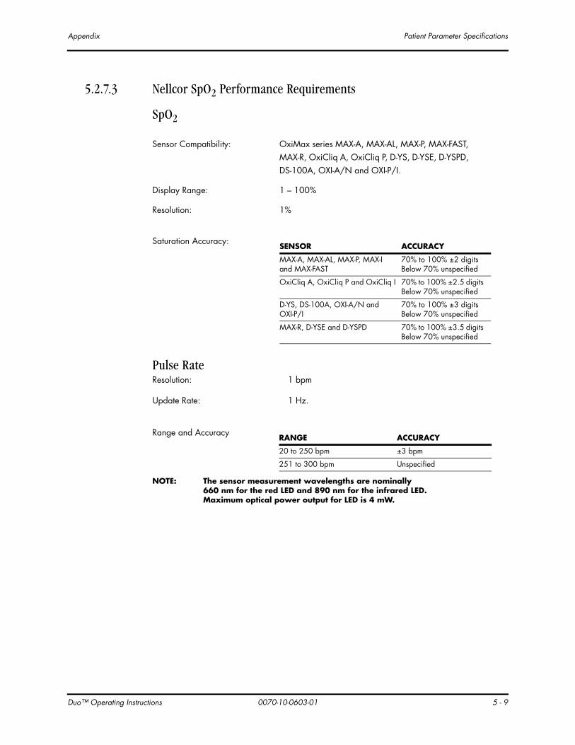
Du
Appendix Patient Parameter Specifications
5.2.7.3 Nellcor SpO2 Performance Requirements
SpO2
Pulse RateResolution: 1 bpm
Update Rate: 1 Hz.
NOTE: The sensor measurement wavelengths are nominally 660 nm for the red LED and 890 nm for the infrared LED. Maximum optical power output for LED is 4 mW.
Sensor Compatibility: OxiMax series MAX-A, MAX-AL, MAX-P, MAX-FAST, MAX-R, OxiCliq A, OxiCliq P, D-YS, D-YSE, D-YSPD, DS-100A, OXI-A/N and OXI-P/I.
Display Range: 1 – 100%
Resolution: 1%
Saturation Accuracy:SENSOR ACCURACY
MAX-A, MAX-AL, MAX-P, MAX-I and MAX-FAST
70% to 100% ±2 digits Below 70% unspecified
OxiCliq A, OxiCliq P and OxiCliq I 70% to 100% ±2.5 digits Below 70% unspecified
D-YS, DS-100A, OXI-A/N and OXI-P/I
70% to 100% ±3 digits Below 70% unspecified
MAX-R, D-YSE and D-YSPD 70% to 100% ±3.5 digits Below 70% unspecified
Range and AccuracyRANGE ACCURACY
20 to 250 bpm ±3 bpm
251 to 300 bpm Unspecified
o™ Operating Instructions 0070-10-0603-01 5 - 9

Patient Parameter Specifications Appendix
5 -
5.2.8 Power Supply
5.2.8.1 Power SourceThe Duo monitor auto-selects its power source from those available. The monitor uses the following priority in choosing the power source:
1. AC Mains Power
2. Internal battery power
The monitor operates from AC Mains power with or without the internal batteries installed.
5.2.9 AC Mains Power Source
5.2.10 Battery Power
5.2.10.1 Lithium Ion Battery: P/N 0146-00-0079The battery pack is 7.2 VDC, 6.6 Amp-hr.
Input Voltage: 100 – 240 VAC (+/-10%)
Line Frequency: 50/60 Hz (+/-3 Hz)
Current: 0.7 – 0.4 Amps
Time to Shutdown from Low Battery:
>10 minutes but < 20 minutes after indication, with 1 new, fully charged battery.
The minimum Battery Run Time: 14.0 hours from one fully charged new battery at 25 °C with continuous SpO2 measurement and NIBP measurements taken at 7 minute intervals.
17.0 hours with NIBP only and measurements taken at 7 minute intervals.
17.5 hours with continuous SpO2 measurement and no NIBP measurements being taken.
The Battery Charge Time: 4.5 hours maximum.
10 0070-10-0603-01 Duo™ Operating Instructions
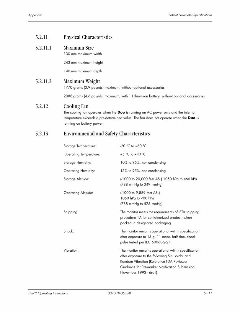
Du
Appendix Patient Parameter Specifications
5.2.11 Physical Characteristics
5.2.11.1 Maximum Size130 mm maximum width
243 mm maximum height
140 mm maximum depth
5.2.11.2 Maximum Weight1770 grams (3.9 pounds) maximum, without optional accessories
2088 grams (4.6 pounds) maximum, with 1 Lithium-ion battery, without optional accessories
5.2.12 Cooling FanThe cooling fan operates when the Duo is running on AC power only and the internal temperature exceeds a pre-determined value. The fan does not operate when the Duo is running on battery power.
5.2.13 Environmental and Safety Characteristics
Storage Temperature: -20 ºC to +60 ºC
Operating Temperature: +5 ºC to +40 ºC
Storage Humidity: 10% to 95%, non-condensing
Operating Humidity: 15% to 95%, non-condensing
Storage Altitude: (-1000 to 20,000 feet ASL) 1050 hPa to 466 hPa (788 mmHg to 349 mmHg)
Operating Altitude: (-1000 to 9,889 feet ASL)1050 hPa to 700 hPa(788 mmHg to 525 mmHg)
Shipping: The monitor meets the requirements of ISTA shipping procedure 1A for containerized product, when packed in designated packaging.
Shock: The monitor remains operational within specification after exposure to 15 g, 11 msec, half sine, shock pulse tested per IEC 60068-2-27.
Vibration: The monitor remains operational within specification after exposure to the following Sinusoidal and Random Vibration (Reference FDA Reviewer Guidance for Pre-market Notification Submission, November 1993 - draft):
o™ Operating Instructions 0070-10-0603-01 5 - 11

Patient Parameter Specifications Appendix
5 -
Sinusoidal Vibration: Per IEC 60068-2-61 g or 0.07 mm, 57 – 62 Hz crossover frequency10 to 500 Hz, 10 sweep cycles in each axis
Random Vibration: Per IEC 60068-2-340.02 g2/Hz20 – 500 HzLow degree of reproducibility9 minutes per axis
Drop: The monitor meets the requirements specified by ECRI PB-296 892 section AIII 3.3 for Class 3 devices.
Impact: The monitor meet the requirements specified by ECRI PB-296892, section AIII 3.2 for Class 3 devices.
12 0070-10-0603-01 Duo™ Operating Instructions

Du
Appendix Patient Parameter Specifications
Electromagnetic Compatibility• The Duo meets the requirements of IEC 60601-1-2:2001/EN 60601-1-2:2001.
NOTE: The Duo needs special precautions regarding EMC and needs to be installed and put into service according to the EMC information provided below.
NOTE: Portable and mobile RF communications equipment can affect the Duo. See TABLE 5-1 through TABLE 5-4.
TABLE 5-1
GUIDANCE AND DECLARATION - ELECTROMAGNETIC EMISSIONS
The Duo is intended for use in the electromagnetic environment specified below. The customer or the user of the Duo should assure that it is used in such an environment.
EMISSIONS TEST COMPLIANCE ELECTROMAGNETIC ENVIRONMENT - GUIDANCE
RF emissions CISPR 11
Group 1 The Duo uses RF energy only for its internal function. Therefore, its RF emissions are very low and are not likely to cause any interference in nearby electronic equipment.
RF emissions CISPR 11
Class A The Duo is suitable for use in all establishments other than domestic establishments and those directly connected to the public low-voltage power supply network that supplies buildings used for domestic purposes
Harmonic emissions IEC 61000-3-2
Class A
Voltage fluctuations/Flicker emissions IEC 61000-3-3
Complies
TABLE 5-2
GUIDANCE AND DECLARATION - ELECTROMAGNETIC IMMUNITY
The Duo is intended for use in the electromagnetic environment specified below. The customer or the user of the Duo should assure that it is used in such an environment.
IMMUNITY TEST
IEC 60601 TEST LEVEL
COMPLIANCE LEVEL
ELECTROMAGNETIC ENVIRONMENT - GUIDANCE
Electrostatic discharge (ESD) IEC 61000-4-2
±6 kV contact ±8 kV air
±6 kV contact ±8 kV air
Floors should be wood, concrete or ceramic tile. If floors are covered with synthetic material, the relative humidity should be at least 30%.
Electrical fast transient/burst IEC 61000-4-4
±2 kV for power supply lines ±1 kV for input/output lines
±2 kV for power supply lines ±1 kV for input/output lines
Mains power quality should be that of a typical commercial or hospital environment.
Surge IEC 61000-4-5
±1 kV differential mode ±2 kV common mode
±1 kV differential mode ±2 kV common mode
Mains power quality should be that of a typical commercial or hospital environment.
o™ Operating Instructions 0070-10-0603-01 5 - 13

Patient Parameter Specifications Appendix
5 -
Voltage dips, short interruptions and voltage variations on power supply input lines IEC 61000-4-11
<5% UΤ (>95% dip in UT) for 0.5 cycle
40% UT (60% dip in UT) for 5 cycles
70% UT (30% dip in UT) for 25 cycles
<5% UT (>95% dip in UT) for 5 sec.
<5% UΤ (>95% dip in UT) for 0.5 cycle
40% UT (60% dip in UT) for 5 cycles
70% UT (30% dip in UT) for 25 cycles
<5% UT (>95% dip in UT) for 5 sec.
Mains power quality should be that of a typical commercial or hospital environment. If the user of the Duo requires continued operation during power mains interruptions, it is recommended that the Duo be powered from an uninterruptible power supply or a battery.
Power frequency (50/60 Hz) magnetic field IEC 61000-4-8
3 A/m 3 A/m Power frequency magnetic fields should be at levels characteristic of a typical location in a typical commercial or hospital environment.
UT is the A.C. mains voltage prior to application of the test level.
TABLE 5-2
GUIDANCE AND DECLARATION - ELECTROMAGNETIC IMMUNITY
The Duo is intended for use in the electromagnetic environment specified below. The customer or the user of the Duo should assure that it is used in such an environment.
IMMUNITY TEST
IEC 60601 TEST LEVEL
COMPLIANCE LEVEL
ELECTROMAGNETIC ENVIRONMENT - GUIDANCE
14 0070-10-0603-01 Duo™ Operating Instructions

Du
Appendix Patient Parameter Specifications
TABLE 5-3
GUIDANCE AND DECLARATION - ELECTROMAGNETIC IMMUNITY
The Duo is intended for use in the electromagnetic environment specified below. The customer or the user of the Duo should assure that it is used in such an environment.
IMMUNITY TEST
IEC 60601 TEST LEVEL
COMPLIANCE LEVEL
ELECTROMAGNETIC ENVIRONMENT - GUIDANCE
Portable and mobile RF communications equipment should be used no closer to any part of the Duo, including cables, than the recommended separation distance calculated from the equation applicable to the frequency of the transmitter.
Recommended separation distance
Conducted RF IEC 61000-4-6
3 Vrms150 kHz to 80 MHz
3 Vrms d = 1.2 x
Radiated RF IEC 61000-4-3
3 V/m80 MHz to 2.5 GHz
3 V/m d = 1.2 x 80 MHz to 800 MHz
d = 2.3 x 800 MHz to 2.5 GHz
where P is the maximum output power rating of the transmitter in watts (W) according to the transmitter manufacturer and d is the recommended separation distance in meters (m).
Field strengths from fixed RF transmitters, as determined by an electromagnetic site survey,a should be less than the compliance level in each frequency range.b
Interference may occur in the vicinity of equipment marked with the following symbol:
NOTE: At 80 MHz and 800 MHz, the higher frequency range applies.
NOTE: These guidelines may not apply in all situations. Electromagnetic propagation is affected by absorption and reflection from structures, objects and people.
a Field strengths from fixed transmitters, such as base stations for radio (cellular/cordless) telephones and land mobile radios, amateur radio, AM and FM radio broadcast and TV broadcast cannot be predicted theo-retically with accuracy. To assess the electromagnetic environment due to fixed RF transmitters, an electro-magnetic site survey should be considered. If the measured field strength in the location in which the Duo is used exceeds the applicable RF compliance level above, the Duo should be observed to verify normal opera-tion. If abnormal performance is observed, additional measures may be necessary, such as reorienting or relocating the Duo.
b Over the frequency range 150 kHz to 80 MHz, field strengths should be less than 3 V/m.
P
P
P
o™ Operating Instructions 0070-10-0603-01 5 - 15

Patient Parameter Specifications Appendix
5 -
NOTE: The Duo is intended for use in the electromagnetic environment specified below. The customer or the user of the Duo should assure that it is used in such an environment.
• The Duo meets the additional electromagnetic compatibility requirements of the FDA Reviewer Guidance for Pre-market Notification Submission, November 1993 listed below:
AC Voltage Dropout: < 10 ms
NOTE: Mains power quality should be that of a typical commercial or hospital environment. If the user of the Duo requires continued operation during power mains interruptions, it is recommended that the Duo be powered from an uninterruptible power supply or a battery.
AC Slow Sags and Surge: 90 V to 150 V for 500 ms
AC Steady State Voltage: 95 – 132 V, AC/battery switching below 95 V
Quasi-static Fields: 500 – 2000 V/m sweep at 0.5 Hz sine
Magnetic Emissions: MIL-STD-461D, RE101, 30 Hz to 100 kHz @ 7 cm
TABLE 5-4
RECOMMENDED SEPARATION DISTANCES BETWEEN PORTABLE AND MOBILE RF COMMUNICATIONS EQUIPMENT AND THE DUO
The Duo is intended for use in an electromagnetic environment in which radiated RF disturbances are controlled. The customer or the user of the Duo can help prevent electromagnetic interference by maintaining a minimum distance between portable and mobile RF communications equipment (transmitters) and the Duo as recommended below, according to the maximum output power of the communications equipment.
RATED MAXIMUM OUTPUT POWER OF TRANSMITTER W (WATTS)
SEPARATION DISTANCE ACCORDING TO FREQUENCY OF TRANSMITTER M (METERS)
150 kHz to 80 MHz
D = 1.2 x
80 MHz to 800 MHz
D = 1.2 x
800 MHz to 2.5 GHz
D = 2.3 x
0.01 0.12 0.12 0.23
0.1 0.38 0.38 0.73
1 1.2 1.2 2.3
10 3.8 3.8 7.3
100 12 12 23
For transmitters rated at a maximum output power not listed above, the recommended separation distance d in meters (m) can be determined using the equation applicable to the frequency of the transmitter, where P is the maximum output power rating of the transmitter in watts (W) according to the transmitter manufacturer.
NOTE: At 80 MHz and 800 MHz, the separation distance for the higher frequency range applies.
NOTE: These guidelines may not apply in all situations. Electromagnetic propagation is affected by absorption and reflection from structures, objects and people.
P P P
16 0070-10-0603-01 Duo™ Operating Instructions

Du
Appendix Warranty Statements
5.3 Warranty StatementsMindray DS USA, Inc. warrants that components within the monitor unit will be free from defects in workmanship and materials for the number of years shown on the invoice. Under this extended warranty, Mindray DS USA, Inc. will repair or replace any defective component at no charge for labor and/or materials. This extended warranty does not cover consumable items such as, but not limited to batteries, displays, external cables and sensors.
Recommended preventative maintenance, as prescribed in the Service Manual, is the responsibility of the user, and is not covered by this warranty.
Except as otherwise provided herein, the terms, conditions and limitations of Mindray DS USA, Inc.’s standard warranty will remain in effect.
USA, Canada, Mexico, and Puerto RicoMindray DS USA, Inc. warrants that its products will be free from defects in workmanship and materials for a period of one (1) year from the date of purchase except that disposable or one-time use products are warranted to be free from defects in workmanship and materials up to a date one year from the date of purchase or the date of first use, whichever is sooner. This warranty does not cover consumable items such as, but not limited to, batteries, external cables, sensors, cuffs, hoses, or mounts.
Mindray DS USA, Inc. will not be liable for any incidental, special, or consequential loss, damage, or expense directly or indirectly arising from the use of its products. Liability under this warranty and the buyer’s exclusive remedy under this warranty is limited to servicing or replacing at Mindray DS USA, Inc.’s option at the factory or at an authorized Distributor, any product which will under normal use and service appear to the Company to have been defective in material or workmanship.
No agent, employee, or representative of Mindray DS USA, Inc. has any authority to bind Mindray DS USA, Inc. to any affirmation, representation, or warranty concerning its products, and any affirmation, representation or warranty made by any agent, employee, or representative will not be enforceable by buyer.
This warranty is expressly in lieu of any other express or implied warranties, including any implied warranty or merchantability or fitness, and of any other obligation on the part of the seller.
Damage to any product or parts through misuse, neglect, accident, or by affixing any non-standard accessory attachments or by any customer modification voids this warranty. Mindray DS USA, Inc. makes no warranty whatever in regard to trade accessories, such being subject to the warranty of their respective manufacturers.
A condition of this warranty is that this equipment or any accessories which are claimed to be defective be returned when authorized by Mindray DS USA, Inc., freight prepaid to Mindray DS USA, Inc., Mahwah, New Jersey 07430. Mindray DS USA, Inc. will not have any responsibility in the event of loss or damage in transit.
o™ Operating Instructions 0070-10-0603-01 5 - 17

Warranty Statements Appendix
5 -
Calibration may be performed without the need to disassemble the instrument. It is the responsibility of the purchaser to perform calibration as necessary, in accordance with the instructions provided in this manual.
18 0070-10-0603-01 Duo™ Operating Instructions

Du
Appendix Manufacturer’s Responsibility
5.4 Manufacturer’s ResponsibilityMindray DS USA, Inc. is responsible for the effects on safety, reliability and performance of the equipment only if:
a. assembly operations, extensions, readjustments, modifications or repairs are performed by persons authorized by Mindray DS USA, Inc.; and
b. the electrical installation of the relevant room complies with the appropriate requirements; and
c. the equipment is used in accordance with the instructions for use.
o™ Operating Instructions 0070-10-0603-01 5 - 19

0070-10-0603-01 Rev E May 24, 2010

0002-08-8918
Mindray DS USA, Inc. • 800 MacArthur Boulevard • Mahwah, NJ 07430 • USA • Dom. Customer Service: 1.800.288.2121 • Intl. Customer Service: +1.201.995.8000 • Dom. Fax: 1.800.926.4275 • Intl. Fax: +1.201.995.8680 • www.mindray.com
Mindray Medical Netherlands B.V.• P.O. Box 26 • 3870 CA Hoevelaken • The Netherlands • Tel: +31 33 25 44 911 • Fax: +31 33 25 37 621
Mindray (UK) Limited • 3 Percy Road • St. John’s Park • Huntingdon • Cambridgeshire PE29 6SZ • United Kingdom • Tel: 01480 416840 • Fax: 01480 436588
Mindray Medical France SARL • Europarc Créteil •123, Chemin des Bassins • 94035 Créteil Cedex • France • Tel: (0)1.45.13.91.50 • Fax: (0)1.45.13.91.51
Mindray Medical German GmbH • Zwischen den Bächen 4 • 64625 Bensheim • Germany • Tel: +49.6251.17524-0 • Fax: +49.6251.17524-20
Mindray Medical International Ltd. • 2813 Office Tower, Convention Plaza • No 1 Harbour Road • Wanchai • Hong Kong • Tel: +852 2793 5596 • Fax: +852 2344 8824