Embed Size (px)
DESCRIPTION
Rosemouth 0065 termowell catalogue
Citation preview
Product Data Sheet00813-0200-2654, Rev GA
Catalog 2006 - 2007 Sensors and Accessories (Metric)
Temperature Sensors and Accessories
(Metric Version)
Content
www.ro
Introduction . . . . . . . . . . . . . . . . . . . . . . . . . . . . . . . . . . . . . . . . . . . . . . . . . . . . . . . . . . . . . . page 2
Integral Mount Sensors and Assemblies. . . . . . . . . . . . . . . . . . . . . . . . . . . . . . . . . . . . . . . . page 3
Mounting Configurations . . . . . . . . . . . . . . . . . . . . . . . . . . . . . . . . . . . . . . . . . . . . . . . . . . . . page 3
Specifications . . . . . . . . . . . . . . . . . . . . . . . . . . . . . . . . . . . . . . . . . . . . . . . . . . . . . . . . . . . . page 4
Hazardous Locations Certification. . . . . . . . . . . . . . . . . . . . . . . . . . . . . . . . . . . . . . . . . . . . . page 5
Sensor-to-Transmitter Matching . . . . . . . . . . . . . . . . . . . . . . . . . . . . . . . . . . . . . . . . . . . . . . page 6
Calibration . . . . . . . . . . . . . . . . . . . . . . . . . . . . . . . . . . . . . . . . . . . . . . . . . . . . . . . . . . . . . . . page 7
Ordering Tables . . . . . . . . . . . . . . . . . . . . . . . . . . . . . . . . . . . . . . . . . . . . . . . . . . . . . . . . . . . page 9
Series 65 and 185 Without Thermowell . . . . . . . . . . . . . . . . . . . . . . . . . . . . . . . . . . . . . . page 9
Series 65 and 185 With Tubular Thermowell . . . . . . . . . . . . . . . . . . . . . . . . . . . . . . . . . page 13
Series 65 and 185 With Barstock Thermowell . . . . . . . . . . . . . . . . . . . . . . . . . . . . . . . . page 17
Series 96 Barstock Thermowell . . . . . . . . . . . . . . . . . . . . . . . . . . . . . . . . . . . . . . . . . . . page 23
Accessories . . . . . . . . . . . . . . . . . . . . . . . . . . . . . . . . . . . . . . . . . . . . . . . . . . . . . . . . . . . . . page 20
Thermowell Strength Calculation. . . . . . . . . . . . . . . . . . . . . . . . . . . . . . . . . . . . . . . . . . . . . page 25
semount.com
Product Data Sheet00813-0200-2654, Rev GA
Catalog 2006 - 2007Sensors and Accessories (Metric)
Introduction
OverviewRosemount integral mount temperature sensors,
accessory hardware, and assemblies constitute a
complete line of industrial temperature-sensing
instruments. A variety of RTD and thermocouple
sensors are available alone or as complete
assemblies including connection heads, thermowells,
and extension fittings. This offering is designed to be
used in complete temperature measurement
assemblies including Rosemount Smart and
Programmable Temperature Transmitters. Please
ask your Rosemount representative for details.
Series 65 Platinum RTD Temperature Sensors
exhibit a highly linear and stable resistance versus
temperature relationship. These sensors are used
primarily in industrial environments where high
accuracy, durability, and long-term stability are
required. Series 65 sensors are designed to meet the
most critical parameters of international standards:
DIN EN 60751 incorporating Amendments 1 and 2,
DIN 43760, and BS 1904.(1) This standardization
provides sensor interchangeability without the need
for transmitter circuitry adjustment.
Enhanced performance and optimal temperature
measurement accuracy is available for Series 65
sensors coupled with a range of smart temperature
transmitters through calibration schedules and
Callendar van Dusen constants.
Series 185 Thermocouple Temperature Sensors
conform to IEC 584 and are available in types J, K
and N. Series 185 sensors are available single
ungrounded, or dual ungrounded, isolated.
All sensors are available in a variety of lengths(2) and
ranges with flying lead, terminal block, or 1/2-inch
ANPT spring-loaded adapter lead wire terminations.
In addition to complete assemblies, Rosemount
Measurement Division offers a selection of separate
accessory hardware including connection heads and
thermowells.
Choosing an Extension and ThermowellAside from ambient temperature variations, heat
from the process, in a direct mounting configuration,
is transferred from the thermowell to the transmitter
housing. If the expected process temperature is near
or beyond the transmitter specification limits,
consider the use of additional thermowell extension
length, an extension nipple, or a remote mounting
configuration to isolate the transmitter from these
excessive temperatures. Figure 1 provides an
example of the relationship between transmitter
housing temperature rise and extension length. Use
Figure 1 and the accompanying example as a guide
for determining adequate thermowell extension
length.
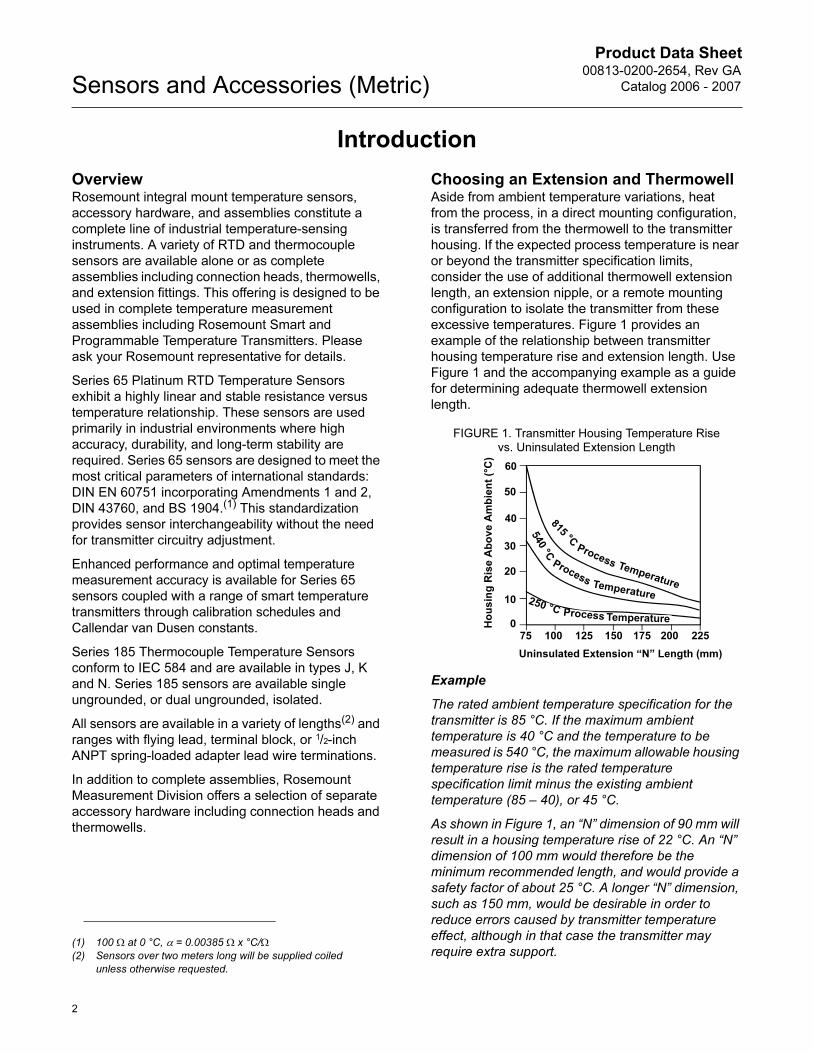
FIGURE 1. Transmitter Housing Temperature Rise vs. Uninsulated Extension Length
Example
The rated ambient temperature specification for the
transmitter is 85 °C. If the maximum ambient
temperature is 40 °C and the temperature to be
measured is 540 °C, the maximum allowable housing
temperature rise is the rated temperature
specification limit minus the existing ambient
temperature (85 – 40), or 45 °C.
As shown in Figure 1, an “N” dimension of 90 mm will
result in a housing temperature rise of 22 °C. An “N”
dimension of 100 mm would therefore be the
minimum recommended length, and would provide a
safety factor of about 25 °C. A longer “N” dimension,
such as 150 mm, would be desirable in order to
reduce errors caused by transmitter temperature
effect, although in that case the transmitter may
require extra support.(1) 100 Ω at 0 °C, α = 0.00385 Ω x °C/Ω
(2) Sensors over two meters long will be supplied coiled
unless otherwise requested.
60
50
40
30
20
10
075 100 125 150 175 200 225
Ho
us
ing
Ris
e A
bo
ve
Am
bie
nt
(°C
)
Uninsulated Extension “N” Length (mm)
815 °C
Process Temperature
540 °C
ProcessTemperature
250 °CProcess Temperature
2
Product Data Sheet00813-0200-2654, Rev GA
Catalog 2006 - 2007 Sensors and Accessories (Metric)
INTEGRAL MOUNT SENSORS AND ASSEMBLIES
Series 65 RTD and Series 185 Thermocouple
Temperature Sensors may be ordered as complete
assemblies. These assemblies provide a complete,
yet simple means of specifying the proper industrial
hardware for most temperature measurements. One
assembly model number, derived from one ordering
table, completely defines the type of sensing
element, as well as the material, length, and style of
extension fittings and thermowells.
All sensor assemblies are sized and inspected by
Rosemount Measurement Division to ensure
complete component compatibility and performance.
MOUNTING CONFIGURATIONS
Series 65 Platinum RTDs
and Series 185 Thermocouples
You may order the Series 65 RTDs and the Series
185 Thermocouples with flying leads, a terminal
block, or a 1/2-inch ANPT spring-loaded adapter.
Ordered with flying leads, the sensors are designed
to be used with a head-mount temperature
transmitter attached directly to the sensor. The flying
lead configuration facilitates removal of the sensor
and transmitter as one assembly.
The BUZH connection head allows terminal block
style sensors and transmitters to be mounted
together. The transmitters in these assemblies will be
mounted in the cover of the BUZH connection head.
The sensors with a 1/2-inch ANPT spring-loaded
adapter are for use with directly mounted 3144P or
3244MV field-mount temperature transmitters or
through the use of Rosemount connection heads.
These assemblies require a terminal block to be
mounted inside the head.
Hazardous area approvals are available with all three
types of sensors, but they are dependent on the
configuration of the entire temperature measurement
assembly (see “Hazardous Locations Certification”
on page 5).
Temperature Considerations
Ambient temperature limits for the connection head
are -40° C to +85° C. The LT Option may be
extended down to a range of -51° C to +85° C.
Ambient temperature range addresses the
connection head only, and requires suitable cable
glands and field wiring provisions to meet the
temperature requirements below -40° C.
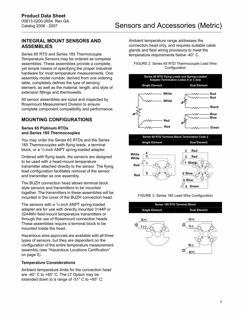
FIGURE 2. Series 65 RTD Thermocouple Lead Wire Configuration
FIGURE 3. Series 185 Lead Wire Configuration
Series 65 RTD Flying Leads and Spring-Loaded Adapter-Termination Codes 0 or 3 only
Single Element Dual Element
Series 65 RTD Terminal Block Termination Code 2
Single Element Dual Element
Series 185 RTD Terminal Block
Single Element Dual Element
Red
White
White
Red
Red
Red
Green
BlueBlue
Black
3
4
1
6
Red
Red
White
White
6
1
34
12
3
45
6
4
5
6
1
2
3 Red
Red
Black
Blue
Blue
Green
31
1 (-)
3(+)
1 3
46
4(+)
6(-)
1(-)
3(+)
3
Product Data Sheet00813-0200-2654, Rev GA
Catalog 2006 - 2007Sensors and Accessories (Metric)
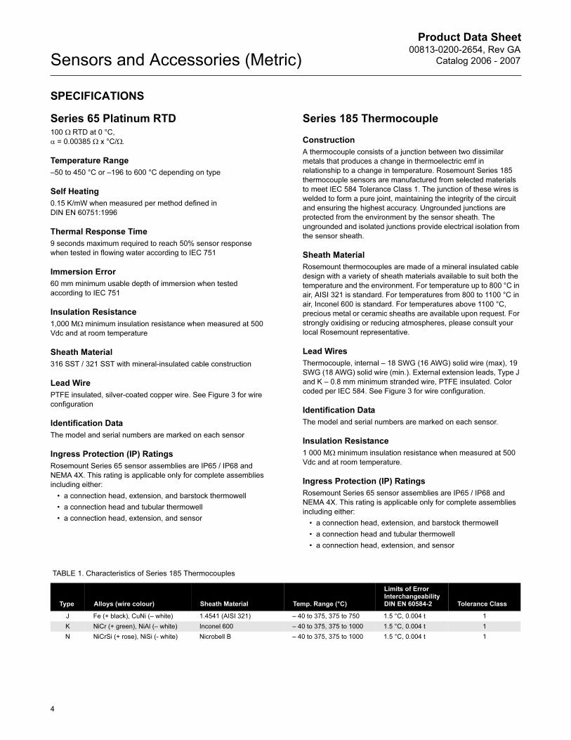
SPECIFICATIONS
Series 65 Platinum RTD100 Ω RTD at 0 °C,
α = 0.00385 Ω x °C/Ω.
Temperature Range
–50 to 450 °C or –196 to 600 °C depending on type
Self Heating
0.15 K/mW when measured per method defined in
DIN EN 60751:1996
Thermal Response Time
9 seconds maximum required to reach 50% sensor response
when tested in flowing water according to IEC 751
Immersion Error
60 mm minimum usable depth of immersion when tested
according to IEC 751
Insulation Resistance
1,000 MΩ minimum insulation resistance when measured at 500
Vdc and at room temperature
Sheath Material
316 SST / 321 SST with mineral-insulated cable construction
Lead Wire
PTFE insulated, silver-coated copper wire. See Figure 3 for wire
configuration
Identification Data
The model and serial numbers are marked on each sensor
Ingress Protection (IP) Ratings
Rosemount Series 65 sensor assemblies are IP65 / IP68 and
NEMA 4X. This rating is applicable only for complete assemblies
including either:
• a connection head, extension, and barstock thermowell
• a connection head and tubular thermowell
• a connection head, extension, and sensor
Series 185 Thermocouple
Construction
A thermocouple consists of a junction between two dissimilar
metals that produces a change in thermoelectric emf in
relationship to a change in temperature. Rosemount Series 185
thermocouple sensors are manufactured from selected materials
to meet IEC 584 Tolerance Class 1. The junction of these wires is
welded to form a pure joint, maintaining the integrity of the circuit
and ensuring the highest accuracy. Ungrounded junctions are
protected from the environment by the sensor sheath. The
ungrounded and isolated junctions provide electrical isolation from
the sensor sheath.
Sheath Material
Rosemount thermocouples are made of a mineral insulated cable
design with a variety of sheath materials available to suit both the
temperature and the environment. For temperature up to 800 °C in
air, AISI 321 is standard. For temperatures from 800 to 1100 °C in
air, Inconel 600 is standard. For temperatures above 1100 °C,
precious metal or ceramic sheaths are available upon request. For
strongly oxidising or reducing atmospheres, please consult your
local Rosemount representative.
Lead Wires
Thermocouple, internal – 18 SWG (16 AWG) solid wire (max), 19
SWG (18 AWG) solid wire (min.). External extension leads, Type J
and K – 0.8 mm minimum stranded wire, PTFE insulated. Color
coded per IEC 584. See Figure 3 for wire configuration.
Identification Data
The model and serial numbers are marked on each sensor.
Insulation Resistance
1 000 MΩ minimum insulation resistance when measured at 500
Vdc and at room temperature.
Ingress Protection (IP) Ratings
Rosemount Series 65 sensor assemblies are IP65 / IP68 and
NEMA 4X. This rating is applicable only for complete assemblies
including either:
• a connection head, extension, and barstock thermowell
• a connection head and tubular thermowell
• a connection head, extension, and sensor
TABLE 1. Characteristics of Series 185 Thermocouples
Type Alloys (wire colour) Sheath Material Temp. Range (°C)
Limits of Error Interchangeability DIN EN 60584-2 Tolerance Class
J Fe (+ black), CuNi (– white) 1.4541 (AISI 321) – 40 to 375, 375 to 750 1.5 °C, 0.004 t 1
K NiCr (+ green), NiAl (– white) Inconel 600 – 40 to 375, 375 to 1000 1.5 °C, 0.004 t 1
N NiCrSi (+ rose), NiSi (- white) Nicrobell B – 40 to 375, 375 to 1000 1.5 °C, 0.004 t 1
4
Product Data Sheet00813-0200-2654, Rev GA
Catalog 2006 - 2007 Sensors and Accessories (Metric)
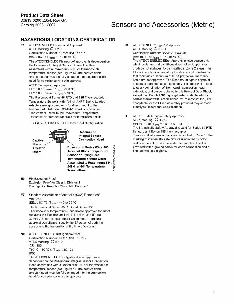
HAZARDOUS LOCATIONS CERTIFICATIONE1 ATEX/CENELEC Flameproof Approval
ATEX Marking II 2 G
Certification Number. KEMA99ATEX8715
EEx d IIC T6 (Tamb = –40 to 65 °C).
The ATEX/CENELEC Flameproof approval is dependent on
the Rosemount Integral Sensor Connection Head
assembled with a Rosemount RTD or thermocouple
temperature sensor (see Figure 4). The captive flame
arrestor insert must be fully engaged into the connection
head for compliance with this approval.
ATEX Flameproof Approval.
EEx d IIC T5 (–40 ≤ Tamb ≤ 80 °C)
EEx d IIC T6 (–40 ≤ Tamb ≤ 70 °C)
The Rosemount Series 65 RTD and 185 Thermocouple
Temperature Sensors with 1/2-inch ANPT Spring Loaded
Adapters are approved only for direct mount to the
Rosemount 3144P and 3244MV Smart Temperature
Transmitters. Refer to the Rosemount Temperature
Transmitter Reference Manuals for installation details.
FIGURE 4. ATEX/CENELEC Flameproof Configuration.
E5 FM Explosion Proof
Explosion Proof for Class I, Division 1
Dust-Ignition Proof for Class II/III, Division 1
E7 Standard Association of Australia (SAA) Flameproof
Approval
(EEx d IIC T6 (Tamb = –40 to 65 °C)
The Rosemount Series 65 RTD and Series 185
Thermocouple Temperature Sensors are approved for direct
mount to the Rosemount 144, 248H, 644, 3144P, and
3244MV Smart Temperature Transmitters. To ensure
approval compliance, specify the E7 option of both the
sensor and the transmitter at the time of ordering.
ND ATEX / CENELEC Dust Ignition-Proof
Certification Number: KEMA99ATEX8715
ATEX Marking: II 1 D
1180
T95 °C (-40 °C ≤ Tamb ≤ 85 °C)
IP66
The ATEX/CENELEC Dust Ignition-Proof approval is
dependent on the Rosemount Integral Sensor Connection
Head assembled with a Rosemount RTD or thermocouple
temperature sensor (see Figure 4). The captive flame
arrestor insert must be fully engaged into the connection
head for compliance with this approval.
N1 ATEX/CENELEC Type “n” Approval
ATEX Marking II 3 G
Certification Number BAS00ATEX3145
[EEx nL II T5 (Tamb = – 40 to 70 °C)]
The ATEX/CENELEC EExn Approval allows equipment,
which under normal conditions does not emit sparks or
produce hot surfaces, to be installed in Zone 2 areas. The
EEx n integrity is achieved by the design and construction
that maintains a minimum of IP 54 protection. Individual
items are not approved. The Rosemount type n approval
applies to complete assemblies only. This approval applies
to every combination of thermowell, connection head,
extension, and sensor detailed in this Product Data Sheet,
except the 1/2-inch ANPT spring-loaded style. In addition,
certain thermowells, not designed by Rosemount Inc., are
acceptable for the EEx n assembly provided they conform
exactly to Rosemount specifications.
I1 ATEX/IBExU Intrinsic Safety Approval
ATEX Marking II 2 G
EEx ia IIC T6 (Tamb = – 51 to 60 °C)
The Intrinsically Safety Approval is valid for Series 65 RTD
Sensors and Series 185 thermocouples.
These certified sensors can only be applied in Zone 1. The
marking of intrinsically safe circuits is effected by color
codes or print, Ex i. A mounted-on connection head is
provided with a ground screw for earth connection and a
blue painted cable gland.
Rosemount
Integral Sensor
Connection Head
Rosemount Series 65 or 185
Terminal Block Temperature
Sensor or Flying Lead
Temperature Sensor when
Assembled to Rosemount 144,
248H, or 644 Temperature
Transmitters
Captive
Flame
Arrestor
Insert
SENSORS-0000A05A
5
Product Data Sheet00813-0200-2654, Rev GA
Catalog 2006 - 2007Sensors and Accessories (Metric)
6
SENSOR-TO-TRANSMITTER MATCHING
Significant measurement accuracy improvements
can be attained using a temperature sensor that is
matched to a temperature transmitter. This process
entails identifying the relationship between
resistance and temperature for a specific RTD
sensor. This relationship, approximated by the
Callendar-van Dusen equation, is described as:
Rt = Ro + Roα[t – δ(0.01t – 1)(0.01t) – β(0.01t – 1)(0.01t)3],
where:
The exact values for the Callendar-van Dusen
constants (Ro, α, δ, β) are specific to each RTD
sensor and are established by testing each individual
sensor at various temperatures.
Series 65 RTD sensors can be ordered with the
Calibration Option codes V10 or V11. When these
options are ordered, the values of all four
sensor-specific constants are supplied with each
sensor. To utilize the unique, built-in sensor-matching
capability of the Rosemount 644, 3144P and
3244MV transmitters, the Callendar-van Dusen
constants can be programmed into the transmitter at
the factory or in the field using a HART
Communicator.
The transmitter uses these Callendar-van Dusen
constants to generate a sensor response curve that
describes the relationship between resistance and
temperature for this particular sensor and transmitter
assembly. By using the sensors actual
resistance-vs.- temperature curve, there is a 3- or
4-fold improvement in temperature measurement
accuracy for the total system.
Options V10 and V11 are specific to a particular
temperature range. As with Calibration Schedules,
the accuracies associated with each option code
represent worst-case conditions when the sensor is
used over the entire temperature range. The
accuracy of Series 65 sensors with the “V” option will
be different because they have different hysteresis
and repeatability characteristics. To ensure optimal
performance, select a “V” option such that the
sensor’s range of actual operation is between the
minimum and maximum calibration points. For those
applications requiring the use of a Resistance vs.
Temperature Table, order a temperature
range-specific characterization schedule.
IEC 751 Interpretation
The Callendar-van Dusen equation is one method of
describing the resistance versus temperature (R
vs.T) relationship for platinum RTDs. International
standard IEC 751 interprets the R vs. T relationship
using an approach that is similar to the Callendar-van
Dusen methodology. The IEC 751 R vs.T relationship
standard is described in the following equation:
Rt = Ro[1 + At + Bt2 + C (t-100)t3]
As in the Callendar-van Dusen method, Ro, A, B, C
are specific to each RTD and are established by
testing each sensor at various temperatures. The
actual values for A, B, and C are different in
magnitude from the Callendar-van Dusen constants
(Ro, α, β, δ). Ro is the same in both equations. Since
one equation is a simple mathematical interpretation
of the other, either methodology yields the same
result in any sensor-to-transmitter matching
scenario.
TABLE 2. Series 65 Interchangeability
Rt = Resistance (ohms) at Temperature t (°C)
Ro = Sensor-Specific Constant (Resistance at t = 0 °C)
α =Sensor-Specific Constant
δ =Sensor-Specific Constant
β =Sensor-Specific Constant (0 at t > 0 °C)
Standard Series 65 IEC-751 Class B Temperature
±0.80 °C (±1.44 °F) -100 °C (-148 °F)
±0.30 °C (±0.54 °F) 0 °C (32 °F)
±0.80 °C (±1.44 °F) 100 °C (212 °F)
±1.80 °C (±3.24 °F) 300 °C (572 °F)
±2.30 °C (±4.14 °F) 400 °C (752 °F)
Series 65 with IEC-751 Class A Option Temperature
±0.35 °C (±0.63 °F) -100 °C (-148 °F)
±0.15 °C (±0.27 °F) 0 °C (32 °F)
±0.35 °C (±0.63 °F) 100 °C (212 °F)
±0.75 °C (±1.35 °F) 300 °C (572 °F)
±0.95 °C (±1.71 °F) 400 °C (752 °F)
Product Data Sheet00813-0200-2654, Rev GA
Catalog 2006 - 2007 Sensors and Accessories (Metric)
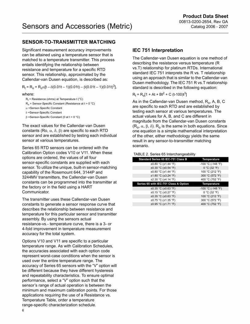
Typical Sensor–to–Transmitter Matching Accuracy Improvements
CALIBRATION
Sensor calibration may be required for input to quality systems, or for control system enhancement. More
frequently, it is used to improve the overall temperature measurement performance by matching the sensor to a
temperature transmitter. Sensor matching is available for RTD sensors used with Rosemount Smart transmitters
where the inherent stability and repeatability of the RTD technology is well established.
Ordering Information
Use the formats presented below to order a calibrated Series 65 RTD. If you fail to specify all of the necessary
calibration-related information when you place your order, Rosemount Measurement Division will contact you for
this information and your order may be slightly delayed.
Calibration Options
The X8 option calibrates the sensor to a customer-specific temperature range. The Callendar van Dusen and A, B,
and C-constants are supplied with a works certificate.
Option X8: Sensor Calibrated to a Customer-Specified Temperature Range (see Temperature Range)
When you order an RTD with the X8 option, you must specify a temperature range to which the sensor must be
calibrated. Before specifying a range, take careful note of the sensor temperature limits
Option V: Sensor Calibration with Works Certificate
Transmitter: Rosemount 3144 (has built-in sensor matching capabilities), span of 0 to 200 °C, accuracy = 0.1 °C)
Sensor: Series 65 RTD
Callendar van Dusen Option: V10
Process Temperature: 150 °C
System Uncertainty Comparison at 150 °C:
Standard 65 Sensor
Rosemount 3144P: ± 0.10 °C
Standard Series 65 RTD: ± 1.05 °C
Total System(1):
(1) Calculated using RSS statistical method:
± 1.05 °C
65 Sensor with V10 Option
Rosemount 3144P: ± 0.10 °C
Calibrated Sensor Series 65 RTD: ± 0.18°C
Total System(1): ± 0.21 °C
1.05 °C
0.21 °C
1.0 °C
0.75 °C
0.5 °C
Standard With Sensor
Matching
TransmitterAccuracy( )2 SensorAccuracy( )2+=System accuracy = Transmitter accuracy Sensor accuracy
Typical Model
NumberModel
Connection Head
Lead Wire Termination
Sensor Type
Extension Type
Extension Length
Thermowell Material
Immersion Length
Mounting Style
Additional Options
0065 C 2 1 D 0135 D 0225 T12 X8
Calibrate from –10 to 120 °C
Code
V10 V11
Temperature Range (°C) – 50 to 450 0 to 100
Calibration Points (°C) –50 0
100450
050100
7
Product Data Sheet00813-0200-2654, Rev GA
Catalog 2006 - 2007Sensors and Accessories (Metric)
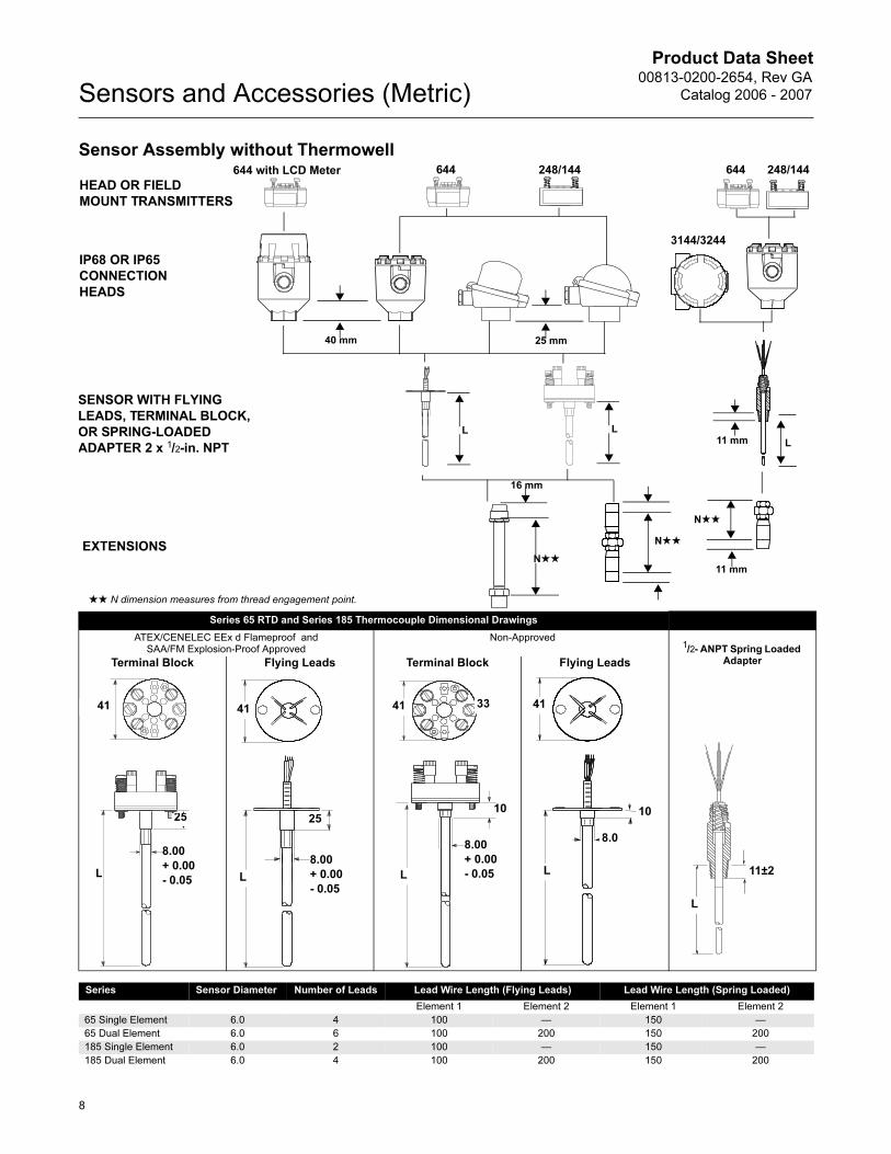
Sensor Assembly without Thermowell
Series 65 RTD and Series 185 Thermocouple Dimensional Drawings
ATEX/CENELEC EEx d Flameproof and SAA/FM Explosion-Proof Approved
Non-Approved1/2- ANPT Spring Loaded
AdapterTerminal Block Flying Leads Terminal Block Flying Leads
248/144644
HEAD OR FIELD
MOUNT TRANSMITTERS
IP68 OR IP65
CONNECTION
HEADS
SENSOR WITH FLYING
LEADS, TERMINAL BLOCK,
OR SPRING-LOADED
ADAPTER 2 x 1/2-in. NPT
EXTENSIONS
644 with LCD Meter
3144/3244
40 mm 25 mm
L
16 mm
N★★
N★★
N★★
LL
★★ N dimension measures from thread engagement point.
248/144644
11 mm
11 mm
11±2
L
41
L
25
8.00
+ 0.00
- 0.05
41
25
L
8.00
+ 0.00
- 0.05
41
L
33
8.00
+ 0.00
- 0.05
10
41
8.0
L
10
Series Sensor Diameter Number of Leads Lead Wire Length (Flying Leads) Lead Wire Length (Spring Loaded)
Element 1 Element 2 Element 1 Element 2
65 Single Element 6.0 4 100 — 150 —
65 Dual Element 6.0 6 100 200 150 200
185 Single Element 6.0 2 100 — 150 —
185 Dual Element 6.0 4 100 200 150 200
8
Product Data Sheet00813-0200-2654, Rev GA
Catalog 2006 - 2007 Sensors and Accessories (Metric)
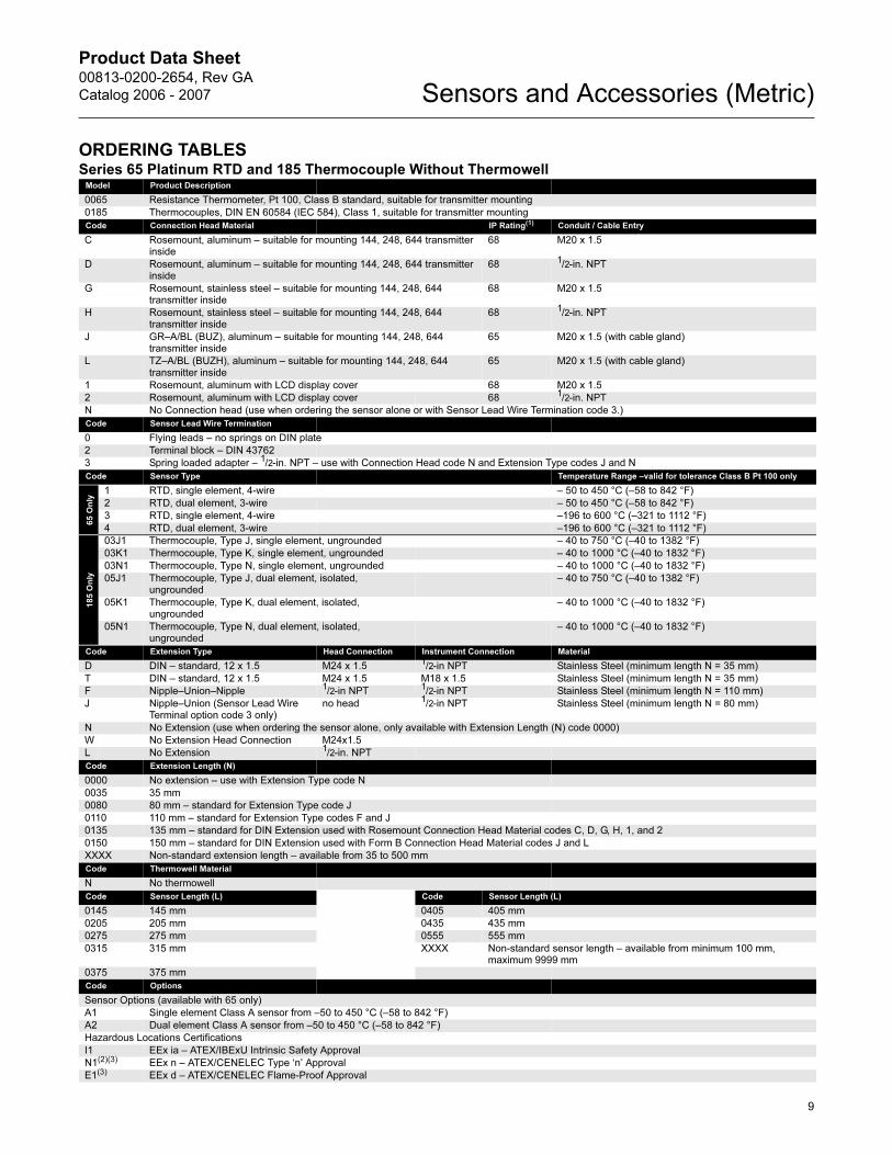
ORDERING TABLESSeries 65 Platinum RTD and 185 Thermocouple Without Thermowell
Model Product Description
0065 Resistance Thermometer, Pt 100, Class B standard, suitable for transmitter mounting
0185 Thermocouples, DIN EN 60584 (IEC 584), Class 1, suitable for transmitter mounting
Code Connection Head Material IP Rating(1) Conduit / Cable Entry
C Rosemount, aluminum – suitable for mounting 144, 248, 644 transmitter inside
68 M20 x 1.5
D Rosemount, aluminum – suitable for mounting 144, 248, 644 transmitter inside
68 1/2-in. NPT
G Rosemount, stainless steel – suitable for mounting 144, 248, 644 transmitter inside
68 M20 x 1.5
H Rosemount, stainless steel – suitable for mounting 144, 248, 644 transmitter inside
68 1/2-in. NPT
J GR–A/BL (BUZ), aluminum – suitable for mounting 144, 248, 644 transmitter inside
65 M20 x 1.5 (with cable gland)
L TZ–A/BL (BUZH), aluminum – suitable for mounting 144, 248, 644 transmitter inside
65 M20 x 1.5 (with cable gland)
1 Rosemount, aluminum with LCD display cover 68 M20 x 1.5
2 Rosemount, aluminum with LCD display cover 68 1/2-in. NPT
N No Connection head (use when ordering the sensor alone or with Sensor Lead Wire Termination code 3.)
Code Sensor Lead Wire Termination
0 Flying leads – no springs on DIN plate
2 Terminal block – DIN 43762
3 Spring loaded adapter – 1/2-in. NPT – use with Connection Head code N and Extension Type codes J and N
Code Sensor Type Temperature Range –valid for tolerance Class B Pt 100 only
65 O
nly
1 RTD, single element, 4-wire – 50 to 450 °C (–58 to 842 °F)
2 RTD, dual element, 3-wire – 50 to 450 °C (–58 to 842 °F)
3 RTD, single element, 4-wire –196 to 600 °C (–321 to 1112 °F)
4 RTD, dual element, 3-wire –196 to 600 °C (–321 to 1112 °F)
185 O
nly
03J1 Thermocouple, Type J, single element, ungrounded – 40 to 750 °C (–40 to 1382 °F)
03K1 Thermocouple, Type K, single element, ungrounded – 40 to 1000 °C (–40 to 1832 °F)
03N1 Thermocouple, Type N, single element, ungrounded – 40 to 1000 °C (–40 to 1832 °F)
05J1 Thermocouple, Type J, dual element, isolated, ungrounded
– 40 to 750 °C (–40 to 1382 °F)
05K1 Thermocouple, Type K, dual element, isolated, ungrounded
– 40 to 1000 °C (–40 to 1832 °F)
05N1 Thermocouple, Type N, dual element, isolated, ungrounded
– 40 to 1000 °C (–40 to 1832 °F)
Code Extension Type Head Connection Instrument Connection Material
D DIN – standard, 12 x 1.5 M24 x 1.5 1/2-in NPT Stainless Steel (minimum length N = 35 mm)
T DIN – standard, 12 x 1.5 M24 x 1.5 M18 x 1.5 Stainless Steel (minimum length N = 35 mm)
F Nipple–Union–Nipple 1/2-in NPT 1/2-in NPT Stainless Steel (minimum length N = 110 mm)
J Nipple–Union (Sensor Lead Wire Terminal option code 3 only)
no head 1/2-in NPT Stainless Steel (minimum length N = 80 mm)
N No Extension (use when ordering the sensor alone, only available with Extension Length (N) code 0000)
W No Extension Head Connection M24x1.5
L No Extension 1/2-in. NPT
Code Extension Length (N)
0000 No extension – use with Extension Type code N
0035 35 mm
0080 80 mm – standard for Extension Type code J
0110 110 mm – standard for Extension Type codes F and J
0135 135 mm – standard for DIN Extension used with Rosemount Connection Head Material codes C, D, G, H, 1, and 2
0150 150 mm – standard for DIN Extension used with Form B Connection Head Material codes J and L
XXXX Non-standard extension length – available from 35 to 500 mm
Code Thermowell Material
N No thermowell
Code Sensor Length (L) Code Sensor Length (L)
0145 145 mm 0405 405 mm
0205 205 mm 0435 435 mm
0275 275 mm 0555 555 mm
0315 315 mm XXXX Non-standard sensor length – available from minimum 100 mm, maximum 9999 mm
0375 375 mm
Code Options
Sensor Options (available with 65 only)
A1 Single element Class A sensor from –50 to 450 °C (–58 to 842 °F)
A2 Dual element Class A sensor from –50 to 450 °C (–58 to 842 °F)
Hazardous Locations Certifications
I1 EEx ia – ATEX/IBExU Intrinsic Safety Approval
N1(2)(3) EEx n – ATEX/CENELEC Type ‘n’ Approval
E1(3) EEx d – ATEX/CENELEC Flame-Proof Approval
9
Product Data Sheet00813-0200-2654, Rev GA
Catalog 2006 - 2007Sensors and Accessories (Metric)
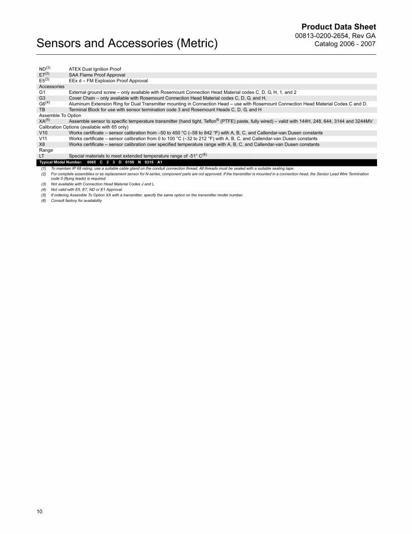
ND(3) ATEX Dust Ignition Proof
E7(3) SAA Flame Proof Approval
E5(3) EEx d – FM Explosion Proof Approval
Accessories
G1 External ground screw – only available with Rosemount Connection Head Material codes C, D, G, H, 1, and 2
G3 Cover Chain – only available with Rosemount Connection Head Material codes C, D, G, and H,
G6(4) Aluminum Extension Ring for Dual Transmitter mounting in Connection Head – use with Rosemount Connection Head Material Codes C and D.
TB Terminal Block for use with sensor termination code 3 and Rosemount Heads C, D, G, and H
Assemble To Option
XA(5) Assemble sensor to specific temperature transmitter (hand tight, Teflon® (PTFE) paste, fully wired) – valid with 144H, 248, 644, 3144 and 3244MV
Calibration Options (available with 65 only)
V10 Works certificate – sensor calibration from –50 to 450 °C (–58 to 842 °F) with A, B, C, and Callendar-van Dusen constants
V11 Works certificate – sensor calibration from 0 to 100 °C (–32 to 212 °F) with A, B, C, and Callendar-van Dusen constants
X8 Works certificate – sensor calibration over specified temperature range with A, B, C, and Callendar-van Dusen constants
Range
LT Special materials to meet extended temperature range of -51° C(6)
Typical Model Number: 0065 C 2 3 D 0150 N 0315 A1
(1) To maintain IP 68 rating, use a suitable cable gland on the conduit connection thread. All threads must be sealed with a suitable sealing tape.
(2) For complete assemblies or as replacement sensor for N-series, component parts are not approved. If the transmitter is mounted in a connection head, the Sensor Lead Wire Termination code 0 (flying leads) is required.
(3) Not available with Connection Head Material Codes J and L.
(4) Not valid with E5, E7, ND or E1 Approval.
(5) If ordering Assemble To Option XA with a transmitter, specify the same option on the transmitter model number.
(6) Consult factory for availability
10
Product Data Sheet00813-0200-2654, Rev GA
Catalog 2006 - 2007 Sensors and Accessories (Metric)
11
Product Data Sheet00813-0200-2654, Rev GA
Catalog 2006 - 2007Sensors and Accessories (Metric)
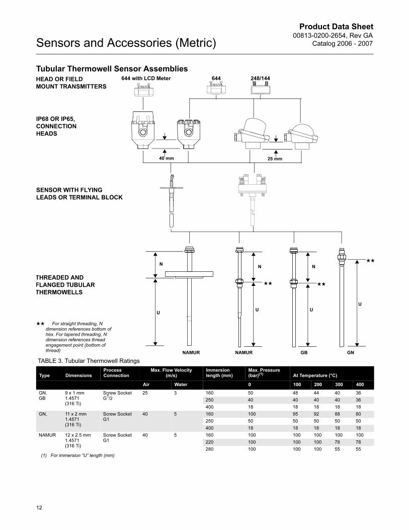
Tubular Thermowell Sensor Assemblies248/144644
IP68 OR IP65,
CONNECTION
HEADS
SENSOR WITH FLYING
LEADS OR TERMINAL BLOCK
THREADED AND
FLANGED TUBULAR
THERMOWELLS
644 with LCD Meter
40 mm
HEAD OR FIELD
MOUNT TRANSMITTERS
N
UU
N
25 mm
NAMUR NAMUR
★★ For straight threading, N dimension references bottom of hex. For tapered threading, N dimension references thread engagement point (bottom of thread)
U
N
U
GB GN
★★ ★★
★★
TABLE 3. Tubular Thermowell Ratings
Type DimensionsProcess Connection
Max. Flow Velocity(m/s)
Immersion length (mm)
Max. Pressure (bar)(1) At Temperature (°C)
Air Water 0 100 200 300 400
GN, GB
9 x 1 mm 1.4571 (316 Ti)
Screw Socket G1/2
25 3 160 50 48 44 40 36
250 40 40 40 40 36
400 18 18 18 18 18
GN, 11 x 2 mm 1.4571(316 Ti)
Screw Socket G1
40 5 160 100 95 92 88 80
250 50 50 50 50 50
400 18 18 18 18 18
NAMUR 12 x 2.5 mm1.4571(316 Ti)
Screw Socket G1
40 5 160 100 100 100 100 100
220 100 100 100 78 78
280 100 100 100 55 55
(1) For immersion “U” length (mm)
12
Product Data Sheet00813-0200-2654, Rev GA
Catalog 2006 - 2007 Sensors and Accessories (Metric)
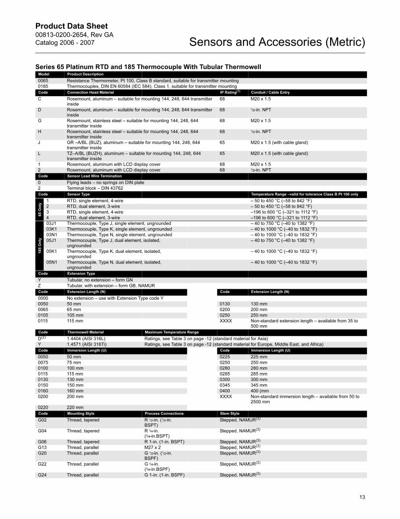
Series 65 Platinum RTD and 185 Thermocouple With Tubular ThermowellModel Product Description
0065 Resistance Thermometer, Pt 100, Class B standard, suitable for transmitter mounting
0185 Thermocouples, DIN EN 60584 (IEC 584), Class 1, suitable for transmitter mounting
Code Connection Head Material IP Rating(1) Conduit / Cable Entry
C Rosemount, aluminum – suitable for mounting 144, 248, 644 transmitter inside
68 M20 x 1.5
D Rosemount, aluminum – suitable for mounting 144, 248, 644 transmitter inside
68 1/2-in. NPT
G Rosemount, stainless steel – suitable for mounting 144, 248, 644 transmitter inside
68 M20 x 1.5
H Rosemount, stainless steel – suitable for mounting 144, 248, 644 transmitter inside
68 1/2-in. NPT
J GR –A/BL (BUZ), aluminum – suitable for mounting 144, 248, 644 transmitter inside
65 M20 x 1.5 (with cable gland)
L TZ–A/BL (BUZH), aluminum – suitable for mounting 144, 248, 644 transmitter inside
65 M20 x 1.5 (with cable gland)
1 Rosemount, aluminum with LCD display cover 68 M20 x 1.5
2 Rosemount, aluminum with LCD display cover 68 1/2-in. NPT
Code Sensor Lead Wire Termination
0 Flying leads – no springs on DIN plate
2 Terminal block – DIN 43762
Code Sensor Type Temperature Range –valid for tolerance Class B Pt 100 only
65 O
nly
1 RTD, single element, 4-wire – 50 to 450 °C (–58 to 842 °F)
2 RTD, dual element, 3-wire – 50 to 450 °C (–58 to 842 °F)
3 RTD, single element, 4-wire –196 to 600 °C (–321 to 1112 °F)
4 RTD, dual element, 3-wire –196 to 600 °C (–321 to 1112 °F)
185 O
nly
03J1 Thermocouple, Type J, single element, ungrounded – 40 to 750 °C (–40 to 1382 °F)
03K1 Thermocouple, Type K, single element, ungrounded – 40 to 1000 °C (–40 to 1832 °F)
03N1 Thermocouple, Type N, single element, ungrounded – 40 to 1000 °C (–40 to 1832 °F)
05J1 Thermocouple, Type J, dual element, isolated, ungrounded
– 40 to 750 °C (–40 to 1382 °F)
05K1 Thermocouple, Type K, dual element, isolated, ungrounded
– 40 to 1000 °C (–40 to 1832 °F)
05N1 Thermocouple, Type N, dual element, isolated, ungrounded
– 40 to 1000 °C (–40 to 1832 °F)
Code Extension Type
Y Tubular, no extension – form GN
Z Tubular, with extension – form GB, NAMUR
Code Extension Length (N) Code Extension Length (N)
0000 No extension – use with Extension Type code Y
0050 50 mm 0130 130 mm
0065 65 mm 0200 200 mm
0105 105 mm 0250 250 mm
0115 115 mm XXXX Non-standard extension length – available from 35 to 500 mm
Code Thermowell Material Maximum Temperature Range
D(2) 1.4404 (AISI 316L) Ratings, see Table 3 on page -12 (standard material for Asia)
Y 1.4571 (AISI 316Ti) Ratings, see Table 3 on page -12 (standard material for Europe, Middle East, and Africa)
Code Immersion Length (U) Code Immersion Length (U)
0050 50 mm 0225 225 mm
0075 75 mm 0250 250 mm
0100 100 mm 0280 280 mm
0115 115 mm 0285 285 mm
0130 130 mm 0300 300 mm
0150 150 mm 0345 345 mm
0160 160 mm 0400 400 (mm
0200 200 mm XXXX Non-standard immersion length – available from 50 to 2500 mm
0220 220 mm
Code Mounting Style Process Connections Stem Style
G02 Thread, tapered R 1/2-in. (1/2-in. BSPT)
Stepped, NAMUR(3)
G04 Thread, tapered R 3/4-in. (3/4-in.BSPT)
Stepped, NAMUR(3)
G06 Thread, tapered R 1-in. (1-in. BSPT) Stepped, NAMUR(3)
G13 Thread, parallel M27 x 2 Stepped, NAMUR(3)
G20 Thread, parallel G 1/2-in. (1/2-in. BSPF)
Stepped, NAMUR(3)
G22 Thread, parallel G 3/4-in. (3/4-in.BSPF)
Stepped, NAMUR(3)
G24 Thread, parallel G 1-in. (1-in. BSPF) Stepped, NAMUR(3)
13
Product Data Sheet00813-0200-2654, Rev GA
Catalog 2006 - 2007Sensors and Accessories (Metric)
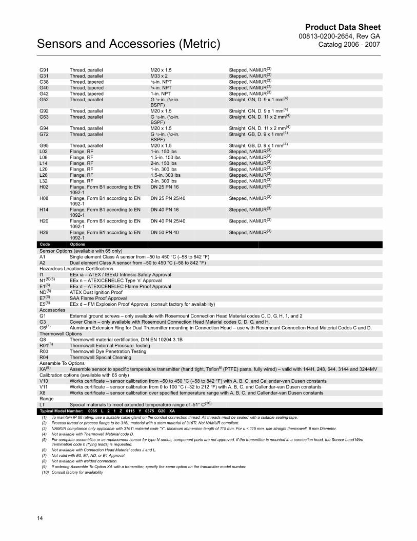
G91 Thread, parallel M20 x 1.5 Stepped, NAMUR(3)
G31 Thread, parallel M33 x 2 Stepped, NAMUR(3)
G38 Thread, tapered 1/2-in. NPT Stepped, NAMUR(3)
G40 Thread, tapered 3/4-in. NPT Stepped, NAMUR(3)
G42 Thread, tapered 1-in. NPT Stepped, NAMUR(3)
G52 Thread, parallel G 1/2-in. (1/2-in. BSPF)
Straight, GN, D. 9 x 1 mm(4)
G92 Thread, parallel M20 x 1.5 Straight, GN, D. 9 x 1 mm(4)
G63 Thread, parallel G 1/2-in. (1/2-in. BSPF)
Straight, GN, D. 11 x 2 mm(4)
G94 Thread, parallel M20 x 1.5 Straight, GN, D. 11 x 2 mm(4)
G72 Thread, parallel G 1/2-in. (1/2-in. BSPF)
Straight, GB, D. 9 x 1 mm(4)
G95 Thread, parallel M20 x 1.5 Straight, GB, D. 9 x 1 mm(4)
L02 Flange, RF 1-in. 150 lbs Stepped, NAMUR(3)
L08 Flange, RF 1.5-in. 150 lbs Stepped, NAMUR(3)
L14 Flange, RF 2-in. 150 lbs Stepped, NAMUR(3)
L20 Flange, RF 1-in. 300 lbs Stepped, NAMUR(3)
L26 Flange, RF 1.5-in. 300 lbs Stepped, NAMUR(3)
L32 Flange, RF 2-in. 300 lbs Stepped, NAMUR(3)
H02 Flange, Form B1 according to EN 1092-1
DN 25 PN 16 Stepped, NAMUR(3)
H08 Flange, Form B1 according to EN 1092-1
DN 25 PN 25/40 Stepped, NAMUR(3)
H14 Flange, Form B1 according to EN 1092-1
DN 40 PN 16 Stepped, NAMUR(3)
H20 Flange, Form B1 according to EN 1092-1
DN 40 PN 25/40 Stepped, NAMUR(3)
H26 Flange, Form B1 according to EN 1092-1
DN 50 PN 40 Stepped, NAMUR(3)
Code Options
Sensor Options (available with 65 only)
A1 Single element Class A sensor from –50 to 450 °C (–58 to 842 °F)
A2 Dual element Class A sensor from –50 to 450 °C (–58 to 842 °F)
Hazardous Locations Certifications
I1 EEx ia – ATEX / IBExU Intrinsic Safety Approval
N1(5)(6) EEx n – ATEX/CENELEC Type ‘n’ Approval
E1(6) EEx d – ATEX/CENELEC Flame Proof Approval
ND(6) ATEX Dust Ignition Proof
E7(6) SAA Flame Proof Approval
E5(6) EEx d – FM Explosion Proof Approval (consult factory for availability)
Accessories
G1 External ground screws – only available with Rosemount Connection Head Material codes C, D, G, H, 1, and 2
G3 Cover Chain – only available with Rosemount Connection Head Material codes C, D, G, and H,
G6(7) Aluminum Extension Ring for Dual Transmitter mounting in Connection Head – use with Rosemount Connection Head Material Codes C and D.
Thermowell Options
Q8 Thermowell material certification, DIN EN 10204 3.1B
R01(8) Thermowell External Pressure Testing
R03 Thermowell Dye Penetration Testing
R04 Thermowell Special Cleaning
Assemble To Options
XA(9) Assemble sensor to specific temperature transmitter (hand tight, Teflon® (PTFE) paste, fully wired) – valid with 144H, 248, 644, 3144 and 3244MV
Calibration options (available with 65 only)
V10 Works certificate – sensor calibration from –50 to 450 °C (–58 to 842 °F) with A, B, C, and Callendar-van Dusen constants
V11 Works certificate – sensor calibration from 0 to 100 °C (–32 to 212 °F) with A, B, C, and Callendar-van Dusen constants
X8 Works certificate – sensor calibration over specified temperature range with A, B, C, and Callendar-van Dusen constants
Range
LT Special materials to meet extended temperature range of -51° C(10)
Typical Model Number: 0065 L 2 1 Z 0115 Y 0375 G20 XA
(1) To maintain IP 68 rating, use a suitable cable gland on the conduit connection thread. All threads must be sealed with a suitable sealing tape.
(2) Process thread or process flange to be 316L material with a stem material of 316Ti. Not NAMUR compliant.
(3) NAMUR compliance only applicable with 316Ti material code “Y”. Minimum immersion length of 115 mm. For u < 115 mm, use straight thermowell, 8 mm Diameter.
(4) Not available with Thermowell Material code D.
(5) For complete assemblies or as replacement sensor for type N-series, component parts are not approved. If the transmitter is mounted in a connection head, the Sensor Lead Wire Termination code 0 (flying leads) is requested.
(6) Not available with Connection Head Material codes J and L.
(7) Not valid with E5, E7, ND, or E1 Approval.
(8) Not available with welded connection.
(9) If ordering Assemble To Option XA with a transmitter, specify the same option on the transmitter model number.
(10) Consult factory for availability
14

Product Data Sheet00813-0200-2654, Rev GA
Catalog 2006 - 2007 Sensors and Accessories (Metric)
15
Product Data Sheet00813-0200-2654, Rev GA
Catalog 2006 - 2007Sensors and Accessories (Metric)
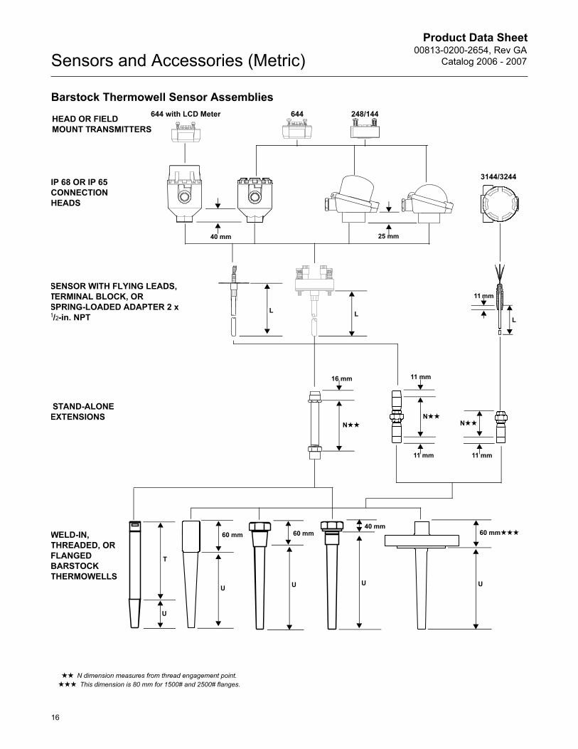
Barstock Thermowell Sensor Assemblies
SENSOR WITH FLYING LEADS,
TERMINAL BLOCK, OR
SPRING-LOADED ADAPTER 2 x 1/2-in. NPT
WELD-IN,
THREADED, OR
FLANGED
BARSTOCK
THERMOWELLS
3144/3244
STAND-ALONE
EXTENSIONS
248/144644
IP 68 OR IP 65
CONNECTION
HEADS
644 with LCD Meter
40 mm
HEAD OR FIELD
MOUNT TRANSMITTERS
11 mm
L
11 mm
16 mm
N★★
11 mm
11 mm
60 mm★★★
UU
U
60 mm
LL
★★ N dimension measures from thread engagement point.
★★★ This dimension is 80 mm for 1500# and 2500# flanges.
N★★N★★
25 mm
T
U
40 mm
U
60 mm
16
Product Data Sheet00813-0200-2654, Rev GA
Catalog 2006 - 2007 Sensors and Accessories (Metric)
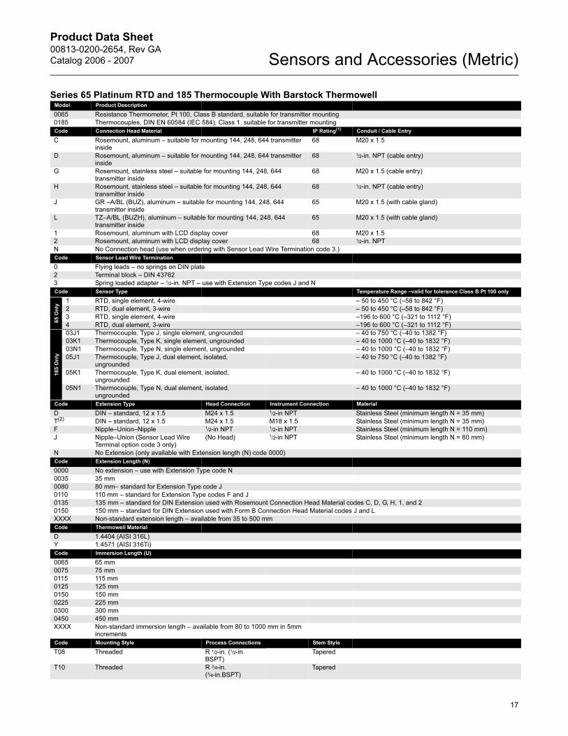
Series 65 Platinum RTD and 185 Thermocouple With Barstock ThermowellModel Product Description
0065 Resistance Thermometer, Pt 100, Class B standard, suitable for transmitter mounting
0185 Thermocouples, DIN EN 60584 (IEC 584), Class 1, suitable for transmitter mounting
Code Connection Head Material IP Rating(1) Conduit / Cable Entry
C Rosemount, aluminum – suitable for mounting 144, 248, 644 transmitter inside
68 M20 x 1.5
D Rosemount, aluminum – suitable for mounting 144, 248, 644 transmitter inside
68 1/2-in. NPT (cable entry)
G Rosemount, stainless steel – suitable for mounting 144, 248, 644 transmitter inside
68 M20 x 1.5 (cable entry)
H Rosemount, stainless steel – suitable for mounting 144, 248, 644 transmitter inside
68 1/2-in. NPT (cable entry)
J GR –A/BL (BUZ), aluminum – suitable for mounting 144, 248, 644 transmitter inside
65 M20 x 1.5 (with cable gland)
L TZ–A/BL (BUZH), aluminum – suitable for mounting 144, 248, 644 transmitter inside
65 M20 x 1.5 (with cable gland)
1 Rosemount, aluminum with LCD display cover 68 M20 x 1.5
2 Rosemount, aluminum with LCD display cover 68 1/2-in. NPT
N No Connection head (use when ordering with Sensor Lead Wire Termination code 3.)
Code Sensor Lead Wire Termination
0 Flying leads – no springs on DIN plate
2 Terminal block – DIN 43762
3 Spring loaded adapter – 1/2-in. NPT – use with Extension Type codes J and N
Code Sensor Type Temperature Range –valid for tolerance Class B Pt 100 only
65 O
nly
1 RTD, single element, 4-wire – 50 to 450 °C (–58 to 842 °F)
2 RTD, dual element, 3-wire – 50 to 450 °C (–58 to 842 °F)
3 RTD, single element, 4-wire –196 to 600 °C (–321 to 1112 °F)
4 RTD, dual element, 3-wire –196 to 600 °C (–321 to 1112 °F)
185 O
nly
03J1 Thermocouple, Type J, single element, ungrounded – 40 to 750 °C (–40 to 1382 °F)
03K1 Thermocouple, Type K, single element, ungrounded – 40 to 1000 °C (–40 to 1832 °F)
03N1 Thermocouple, Type N, single element, ungrounded – 40 to 1000 °C (–40 to 1832 °F)
05J1 Thermocouple, Type J, dual element, isolated, ungrounded
– 40 to 750 °C (–40 to 1382 °F)
05K1 Thermocouple, Type K, dual element, isolated, ungrounded
– 40 to 1000 °C (–40 to 1832 °F)
05N1 Thermocouple, Type N, dual element, isolated, ungrounded
– 40 to 1000 °C (–40 to 1832 °F)
Code Extension Type Head Connection Instrument Connection Material
D DIN – standard, 12 x 1.5 M24 x 1.5 1/2-in NPT Stainless Steel (minimum length N = 35 mm)
T(2) DIN – standard, 12 x 1.5 M24 x 1.5 M18 x 1.5 Stainless Steel (minimum length N = 35 mm)
F Nipple–Union–Nipple 1/2-in NPT 1
/2-in NPT Stainless Steel (minimum length N = 110 mm)
J Nipple–Union (Sensor Lead Wire Terminal option code 3 only)
(No Head) 1/2-in NPT Stainless Steel (minimum length N = 80 mm)
N No Extension (only available with Extension length (N) code 0000)
Code Extension Length (N)
0000 No extension – use with Extension Type code N
0035 35 mm
0080 80 mm– standard for Extension Type code J
0110 110 mm – standard for Extension Type codes F and J
0135 135 mm – standard for DIN Extension used with Rosemount Connection Head Material codes C, D, G, H, 1, and 2
0150 150 mm – standard for DIN Extension used with Form B Connection Head Material codes J and L
XXXX Non-standard extension length – available from 35 to 500 mm
Code Thermowell Material
D 1.4404 (AISI 316L)
Y 1.4571 (AISI 316Ti)
Code Immersion Length (U)
0065 65 mm
0075 75 mm
0115 115 mm
0125 125 mm
0150 150 mm
0225 225 mm
0300 300 mm
0450 450 mm
XXXX Non-standard immersion length – available from 80 to 1000 mm in 5mm increments
Code Mounting Style Process Connections Stem Style
T08 Threaded R 1/2-in. (1/2-in. BSPT)
Tapered
T10 Threaded R 3/4-in. (3/4-in.BSPT)
Tapered
17
Product Data Sheet00813-0200-2654, Rev GA
Catalog 2006 - 2007Sensors and Accessories (Metric)
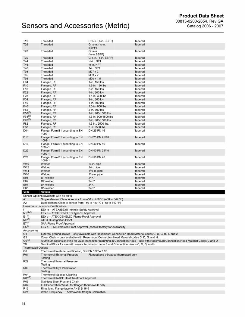
T12 Threaded R 1-in. (1-in. BSPT) Tapered
T26 Threaded G 1/2-in. (1/2-in. BSPF)
Tapered
T28 Threaded G 3/4-in. (3/4-in.BSPF)
Tapered
T30 Threaded G 1-in. (1-in. BSPF) Tapered
T44 Threaded 1/2-in. NPT Tapered
T46 Threaded 3/4-in. NPT Tapered
T48 Threaded 1-in. NPT Tapered
T93 Threaded M27 x 2 Tapered
T95 Threaded M33 x 2 Tapered
T98 Threaded M20 x 1.5 Tapered
F04 Flanged, RF 1-in. 150 lbs Tapered
F10 Flanged, RF 1.5-in. 150 lbs Tapered
F16 Flanged, RF 2-in. 150 lbs Tapered
F22 Flanged, RF 1-in. 300 lbs Tapered
F28 Flanged, RF 1.5-in. 300 lbs Tapered
F34 Flanged, RF 2-in. 300 lbs Tapered
F40 Flanged, RF 1-in. 600 lbs Tapered
F46 Flanged, RF 1.5-in. 600 lbs Tapered
F52 Flanged, RF 2-in. 600 lbs Tapered
F58(3) Flanged, RF 1-in. 900/1500 lbs Tapered
F64(3) Flanged, RF 1.5-in. 900/1500 lbs Tapered
F70(3) Flanged, RF 2-in. 900/1500 lbs Tapered
F82 Flanged, RF 1.5 in., 2500 lbs. Tapered
F88 Flanged, RF 2 in. 2500 lbs. Tapered
D04 Flange, Form B1 according to EN 1092-1
DN 25 PN 16 Tapered
D10 Flange, Form B1 according to EN 1092-1
DN 25 PN 25/40 Tapered
D16 Flange, Form B1 according to EN 1092-1
DN 40 PN 16 Tapered
D22 Flange, Form B1 according to EN 1092-1
DN 40 PN 25/40 Tapered
D28 Flange, Form B1 according to EN 1092-1
DN 50 PN 40 Tapered
W10 Welded 3/4-in. pipe Tapered
W12 Welded 1-in. pipe Tapered
W14 Welded 11/4-in. pipe Tapered
W16 Welded 11/2-in. pipe Tapered
E01 D1 welded 24h7 Tapered
E02 D2 welded 24h7 Tapered
E04 D4 welded 24h7 Tapered
E05 D5 welded 24h7 Tapered
Code Options
Sensor Options (available with 65 only)
A1 Single element Class A sensor from –50 to 450 °C (–58 to 842 °F)
A2 Dual element Class A sensor from –50 to 450 °C (–58 to 842 °F)
Hazardous Locations Certifications
I1 EEx ia – ATEX/IBExU Intrinsic Safety Approval
N1(4)(5) EEx n – ATEX/CENELEC Type ‘n’ Approval
E1(5) EEx d – ATEX/CENELEC Flame-Proof Approval
ND(5) ATEX Dust Ignition Proof
E7(5) SAA Flame Proof Approval
E5(5) EEx d – FM Explosion Proof Approval (consult factory for availability)
Accessories
G1 External ground screws – only available with Rosemount Connection Head Material codes C, D, G, H, 1, and 2
G3 Cover Chain – only available with Rosemount Connection Head Material codes C, D, G, and H,
G6(6) Aluminum Extension Ring for Dual Transmitter mounting in Connection Head – use with Rosemount Connection Head Material Codes C and D.
TB Terminal Block for use with sensor termination code 3 and Connection Heads C, D, G, and H
Thermowell Options
Q8 Thermowell material certification, DIN EN 10204 3.1B
R01 Thermowell External Pressure Testing
Flanged and thjreaded thermowell only
R22 Thermowell Internal Pressure Testing
R03 Thermowell Dye Penetration Testing
R04 Thermowell Special Cleaning
R05(7) Thermowell NACE Heat Treatment Approval
R06 Stainless Steel Plug and Chain
R07 Full Penetration Weld - for flanged thermowells only
R16 Ring Joint; Flange face to ANSI B 16.5
R21 Wake Frequency – Thermowell Strength Calculation
18
Product Data Sheet00813-0200-2654, Rev GA
Catalog 2006 - 2007 Sensors and Accessories (Metric)
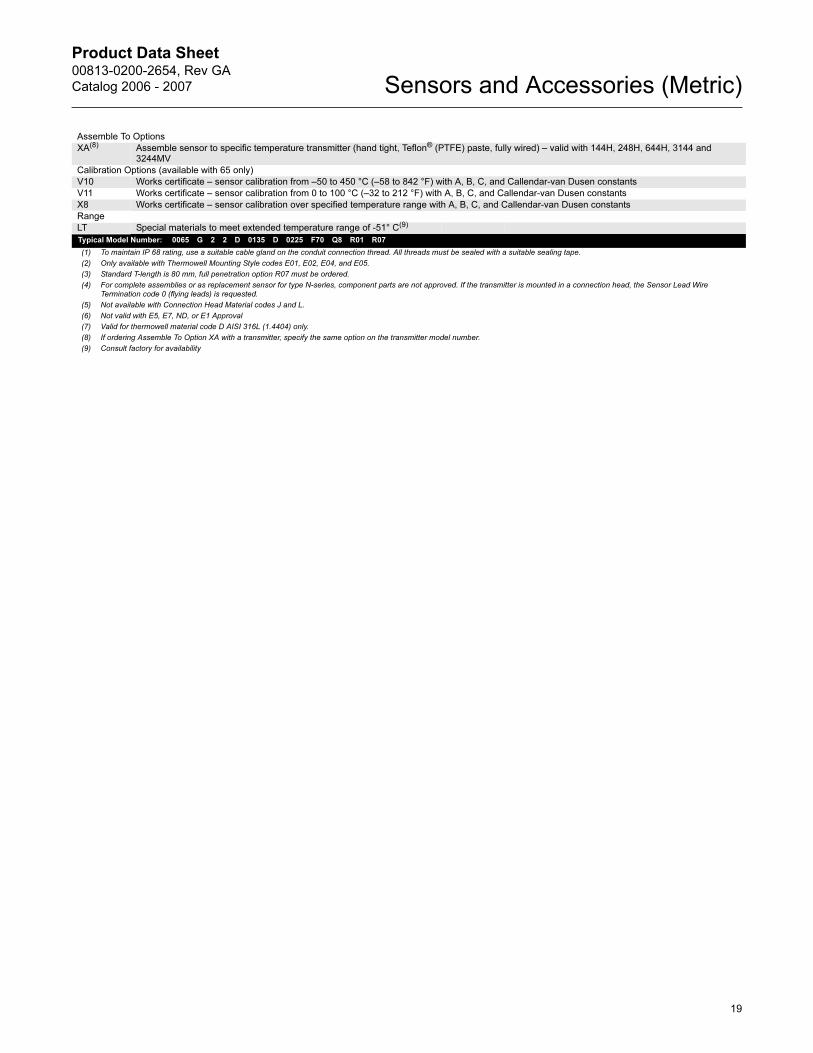
Assemble To Options
XA(8) Assemble sensor to specific temperature transmitter (hand tight, Teflon® (PTFE) paste, fully wired) – valid with 144H, 248H, 644H, 3144 and 3244MV
Calibration Options (available with 65 only)
V10 Works certificate – sensor calibration from –50 to 450 °C (–58 to 842 °F) with A, B, C, and Callendar-van Dusen constants
V11 Works certificate – sensor calibration from 0 to 100 °C (–32 to 212 °F) with A, B, C, and Callendar-van Dusen constants
X8 Works certificate – sensor calibration over specified temperature range with A, B, C, and Callendar-van Dusen constants
Range
LT Special materials to meet extended temperature range of -51° C(9)
Typical Model Number: 0065 G 2 2 D 0135 D 0225 F70 Q8 R01 R07
(1) To maintain IP 68 rating, use a suitable cable gland on the conduit connection thread. All threads must be sealed with a suitable sealing tape.
(2) Only available with Thermowell Mounting Style codes E01, E02, E04, and E05.
(3) Standard T-length is 80 mm, full penetration option R07 must be ordered.
(4) For complete assemblies or as replacement sensor for type N-series, component parts are not approved. If the transmitter is mounted in a connection head, the Sensor Lead Wire Termination code 0 (flying leads) is requested.
(5) Not available with Connection Head Material codes J and L.
(6) Not valid with E5, E7, ND, or E1 Approval
(7) Valid for thermowell material code D AISI 316L (1.4404) only.
(8) If ordering Assemble To Option XA with a transmitter, specify the same option on the transmitter model number.
(9) Consult factory for availability
19
Product Data Sheet00813-0200-2654, Rev GA
Catalog 2006 - 2007Sensors and Accessories (Metric)
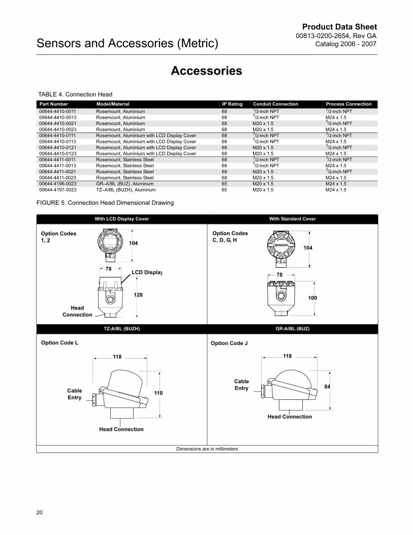
Accessories
TABLE 4. Connection Head
FIGURE 5. Connection Head Dimensional Drawing
Part Number Model/Material IP Rating Conduit Connection Process Connection
00644-4410-0011 Rosemount, Aluminium 68 1/2-inch NPT 1/2-inch NPT
00644-4410-0013 Rosemount, Aluminium 68 1/2-inch NPT M24 x 1.5
00644-4410-0021 Rosemount, Aluminium 68 M20 x 1.5 1/2-inch NPT
00644-4410-0023 Rosemount, Aluminium 68 M20 x 1.5 M24 x 1.5
00644-4410-0111 Rosemount, Aluminium with LCD Display Cover 68 1/2-inch NPT 1/2-inch NPT
00644-4410-0113 Rosemount, Aluminium with LCD Display Cover 68 1/2-inch NPT M24 x 1.5
00644-4410-0121 Rosemount, Aluminium with LCD Display Cover 68 M20 x 1.5 1/2-inch NPT
00644-4410-0123 Rosemount, Aluminium with LCD Display Cover 68 M20 x 1.5 M24 x 1.5
00644-4411-0011 Rosemount, Stainless Steel 68 1/2-inch NPT 1/2-inch NPT
00644-4411-0013 Rosemount, Stainless Steel 68 1/2-inch NPT M24 x 1.5
00644-4411-0021 Rosemount, Stainless Steel 68 M20 x 1.5 1/2-inch NPT
00644-4411-0023 Rosemount, Stainless Steel 68 M20 x 1.5 M24 x 1.5
00644-4196-0023 GR–A/BL (BUZ), Aluminum 65 M20 x 1.5 M24 x 1.5
00644-4197-0023 TZ–A/BL (BUZH), Aluminum 65 M20 x 1.5 M24 x 1.5
With LCD Display Cover With Standard Cover
TZ-A/BL (BUZH) GR-A/BL (BUZ)
Dimensions are in millimeters
104
78
128
LCD Display
Head
Connection
Option Codes
1, 2
104
100
78
Option Codes
C, D, G, H
118
110 Cable
Entry
Head Connection
Option Code L
118
84 Cable
Entry
Head Connection
Option Code J
20
Product Data Sheet00813-0200-2654, Rev GA
Catalog 2006 - 2007 Sensors and Accessories (Metric)
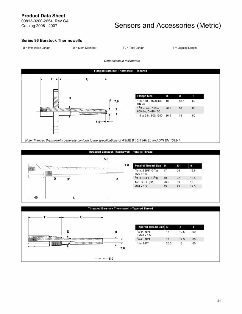
Series 96 Barstock Thermowells
U = Immersion Length D = Stem Diameter TL = Total Length T = Lagging Length
Dimensions in millimeters
Flanged Barstock Thermowell – Tapered
Note: Flanged thermowells generally conform to the specifications of ASME B 16.5 (ANSI) and DIN EN 1092-1.
Threaded Barstock Thermowell – Parallel Thread
Threaded Barstock Thermowell – Tapered Thread
UT
Dd 7.0
5.0
Flange Size D d T
1-in. 150 – 1500 lbs, DN 25
19 12.5 60
11/2 to 2-in. 150 – 600 lbs, DN40 - 50
26.5 18 60
1.5 to 2-in. 900/1500 26.5 18 80
U40
dD
7.0
5.0
Parallel Thread Size D D1 d
1/2-in. BSPF (G1/2); M20 x 1.5
17 26 12.5
3/4-in. BSPF (G3/4) 19 32 12.5
1-in. BSPF (G1) 26.5 39 18
M24 x 1.5 19 29 12.5
D1
U
5.0
T
d
7.0
D
Tapered Thread Size D d T
1/2-in. NPT; M20 x 1.5
17 12.5 60
3/4-in. NPT 19 12.5 60
1-in. NPT 26.5 18 60
21
Product Data Sheet00813-0200-2654, Rev GA
Catalog 2006 - 2007Sensors and Accessories (Metric)
--
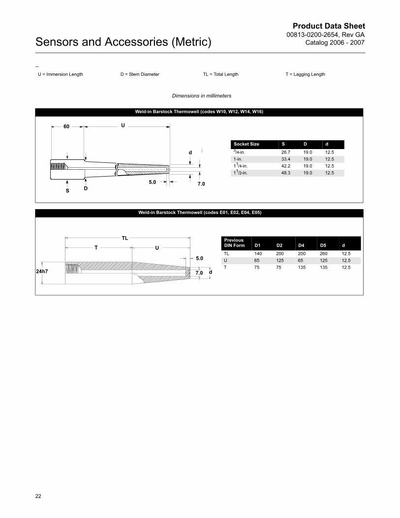
U = Immersion Length D = Stem Diameter TL = Total Length T = Lagging Length
Dimensions in millimeters
Weld-in Barstock Thermowell (codes W10, W12, W14, W16)
Weld-in Barstock Thermowell (codes E01, E02, E04, E05)
UT
dD
U60
DS
d
7.0
Socket Size S D d
3/4-in. 26.7 19.0 12.5
1-in. 33.4 19.0 12.5
11/4-in. 42.2 19.0 12.5
11/2-in. 48.3 19.0 12.5
5.0
UT
d
5.0
TL Previous DIN Form D1 D2 D4 D5 d
TL 140 200 200 260 12.5
U 65 125 65 125 12.5
T 75 75 135 135 12.5
7.024h7
22
Product Data Sheet00813-0200-2654, Rev GA
Catalog 2006 - 2007 Sensors and Accessories (Metric)
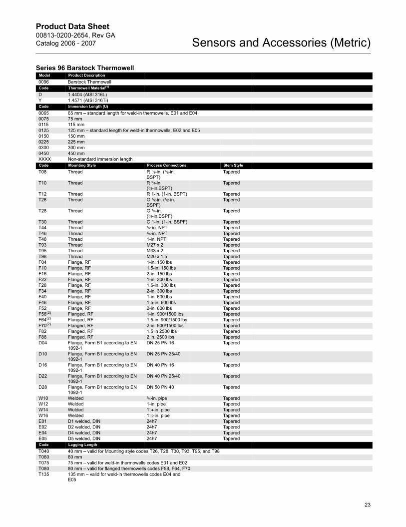
Series 96 Barstock ThermowellModel Product Description
0096 Barstock Thermowell
Code Thermowell Material(1)
D 1.4404 (AISI 316L)
Y 1.4571 (AISI 316Ti)
Code Immersion Length (U)
0065 65 mm – standard length for weld-in thermowells, E01 and E04
0075 75 mm
0115 115 mm
0125 125 mm – standard length for weld-in thermowells, E02 and E05
0150 150 mm
0225 225 mm
0300 300 mm
0450 450 mm
XXXX Non-standard immersion length
Code Mounting Style Process Connections Stem Style
T08 Thread R 1/2-in. (1/2-in. BSPT)
Tapered
T10 Thread R 3/4-in. (3/4-in.BSPT)
Tapered
T12 Thread R 1-in. (1-in. BSPT) Tapered
T26 Thread G 1/2-in. (1/2-in. BSPF)
Tapered
T28 Thread G 3/4-in. (3/4-in.BSPF)
Tapered
T30 Thread G 1-in. (1-in. BSPF) Tapered
T44 Thread 1/2-in. NPT Tapered
T46 Thread 3/4-in. NPT Tapered
T48 Thread 1-in. NPT Tapered
T93 Thread M27 x 2 Tapered
T95 Thread M33 x 2 Tapered
T98 Thread M20 x 1.5 Tapered
F04 Flange, RF 1-in. 150 lbs Tapered
F10 Flange, RF 1.5-in. 150 lbs Tapered
F16 Flange, RF 2-in. 150 lbs Tapered
F22 Flange, RF 1-in. 300 lbs Tapered
F28 Flange, RF 1.5-in. 300 lbs Tapered
F34 Flange, RF 2-in. 300 lbs Tapered
F40 Flange, RF 1-in. 600 lbs Tapered
F46 Flange, RF 1.5-in. 600 lbs Tapered
F52 Flange, RF 2-in. 600 lbs Tapered
F58(2) Flanged, RF 1-in. 900/1500 lbs Tapered
F64(2) Flanged, RF 1.5-in. 900/1500 lbs Tapered
F70(2) Flanged, RF 2-in. 900/1500 lbs Tapered
F82 Flanged, RF 1.5 in 2500 lbs Tapered
F88 Flanged, RF 2 in. 2500 lbs Tapered
D04 Flange, Form B1 according to EN 1092-1
DN 25 PN 16 Tapered
D10 Flange, Form B1 according to EN 1092-1
DN 25 PN 25/40 Tapered
D16 Flange, Form B1 according to EN 1092-1
DN 40 PN 16 Tapered
D22 Flange, Form B1 according to EN 1092-1
DN 40 PN 25/40 Tapered
D28 Flange, Form B1 according to EN 1092-1
DN 50 PN 40 Tapered
W10 Welded 3/4-in. pipe Tapered
W12 Welded 1-in. pipe Tapered
W14 Welded 11/4-in. pipe Tapered
W16 Welded 11/2-in. pipe Tapered
E01 D1 welded, DIN 24h7 Tapered
E02 D2 welded, DIN 24h7 Tapered
E04 D4 welded, DIN 24h7 Tapered
E05 D5 welded, DIN 24h7 Tapered
Code Lagging Length
T040 40 mm – valid for Mounting style codes T26, T28, T30, T93, T95, and T98
T060 60 mm
T075 75 mm – valid for weld-in thermowells codes E01 and E02
T080 80 mm – valid for flanged thermowells codes F58, F64, F70
T135 135 mm – valid for weld-in thermowells codes E04 and E05
23
Product Data Sheet00813-0200-2654, Rev GA
Catalog 2006 - 2007Sensors and Accessories (Metric)
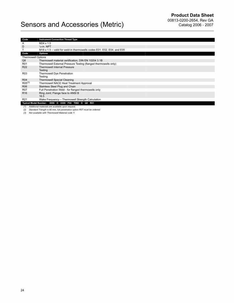
Code Instrument Connection Thread Type
A M24 x 1.5
D 1/2-in. NPT
T M18 x 1.5 – valid for weld-in thermowells codes E01, E02, E04, and E05
Code Options
Thermowell Options
Q8 Thermowell material certification, DIN EN 10204 3.1B
R01 Thermowell External Pressure Testing (flanged thermowells only)
R22 Thermowell Internal Pressure Testing
R03 Thermowell Dye Penetration Testing
R04 Thermowell Special Cleaning
R05(3) Thermowell NACE Heat Treatment Approval
R06 Stainless Steel Plug and Chain
R07 Full Penetration Weld - for flanged thermowells only
R16 Ring Joint; Flange face to ANSI B 16.5
R21 Wake Frequency – Thermowell Strength Calculation
Typical Model Number: 0096 D 0300 F04 T060 D Q8 R01
(1) Additional materials are available upon request.
(2) Standard T-length is 80 mm, full penetration option R07 must be ordered.
(3) Not available with Thermowell Material code Y.
24
Product Data Sheet00813-0200-2654, Rev GA
Catalog 2006 - 2007 Sensors and Accessories (Metric)
Thermowell Strength Calculation
Pressure and Flow Vibration
The strength of a thermowell depends on several
parameters that relate thermowell construction to the
installation environment. For most industrial
applications, standard Rosemount thermowells
provide the necessary strength if the material, style,
and length are correct for the application. The proper
selection of a thermowell depends on fluid type,
temperature, pressure, and fluid velocity. It is
important to note that most thermowell failures are
caused by vibration that is induced by fluid flow.
Rosemount Measurement Division has a design
system for the correct selection of thermowells, given
the application parameters. This selection service is
available for a nominal charge. To take advantage of
this service, complete and return the Thermowell
Strength Calculation, to your local Rosemount
representative.
Rosemount Inc. includes three possible failure
modes in conjunction with thermowell analysis:
Flow-Induced Vibration
Fluid flow past a thermowell causes vortices to be
shed from the well at a frequency, termed the wake
frequency, proportional to the flow velocity. If the
wake frequency is at or near the natural frequency of
a given thermowell, a resonance condition may occur
where a massive amounts of energy are absorbed by
the thermowell, resulting in very high stresses and
possible failures. Even if the thermowell does not fail,
the sensor capsule inside the thermowell may be
subjected to severe levels of shock and vibration,
resulting in erroneous readings or total sensor failure.
The ASME technique requires that the ratio of wake
frequency to natural frequency of a thermowell be
less than 0.8. In instances where the ratio is greater
than 0.8, a user has two options:
1. Decrease the wake frequency by reducing the
flow velocity or using a larger diameter
thermowell, or
2. Increase the natural frequency of the thermowell
by using a stronger thermowell configuration
(a different thermowell type or material, or a
shorter length thermowell).
Flow-Induced Stress
Fluid flow, which is a function of flow velocity and
density, causes a force to be exerted on the
thermowell. The flow-induced stress is calculated
and should be compared with the material strength of
the thermowell.
Process Pressure
The maximum static pressure that a thermowell stem
can undergo is calculated.
NOTE
The thermowell analysis process is intended to be an
aid in choosing thermowells for specific applications.
It is based upon accepted theoretical methods and is
not meant to be a guarantee against
thermowell failure.
25
Product Data Sheet00813-0200-2654, Rev GA
Catalog 2006 - 2007Sensors and Accessories (Metric)
Application Data Sheet
Calculations conducted per ASME/ANSI PTC 19.3 but with Strouhal number varying with Reynolds number. Please complete and fax to
appropriate locations at the bottom of this form.
Company Information
Requesting Company: Phone: Fax:
Contact Tag Number
End Customer Date of Request:
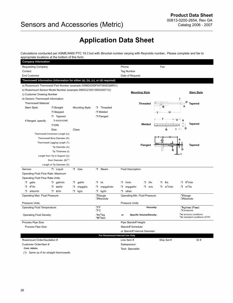
Thermowell Information (Information for either (a), (b), (c), or (d) required)
a) Rosemount Thermowell Part Number (example 0096D0300F04T060DQ8R01):
b) Rosemount Sensor Model Number (example 0065C21D0135D0300T12):
c) Customer Drawing Number
d) Generic Thermowell Information:
Thermowell Material:
Stem Style: ❒ Straight Mounting Style: ❒ Threaded
❒ Stepped ❒ Welded
❒ Tapered ❒ Flanged
If flanged, specify: ❒ ANSI/ASME
❒ DIN
Size: Class:
Thermowell Immersion Length (U):
Thermowell Bore Diameter (D):
Thermowell Lagging Length (T):
Tip Diameter (A):
Tip Thickness (t):
Length from Tip to Support (U):
Root Diameter (B)(1):
(1) Same as A for straight thermowells.
Length of Tip Diameter (Z):
Service: ❒ Liquid ❒ Gas ❒ Steam Fluid Description:
Operating Fluid Flow Rate: Maximum
Operating Fluid Flow Rate Units:
❒ gal/s ❒ gal/min ❒ gal/hr ❒ l/s ❒ l/min ❒ l/hr ❒ ft/s ❒ ft3/min
❒ ft3/hr ❒ bbl/hr ❒ impgal/s ❒ impgal/min ❒ impgal/hr ❒ m/s ❒ m3/min ❒ m3/hr
❒ shton/hr ❒ lb/hr ❒ kg/s ❒ kg/hr ❒ other:
Operating Max. Fluid Pressure: ❒Gauge❒Absolute
Operating Min. Fluid Pressure: ❒Gauge❒Absolute
Pressure Units: Pressure Units:
Operating Fluid Temperature: ❒°F❒°C
Viscosity: ❒kg/m●s (Pa●s)❒Centipoise
Operating Fluid Density: ❒m3/kg❒ft3/lbm
or Specific Volume/Density: ❒at process conditions❒at standard conditions (STP)
Process Pipe Size: Pipe Standoff Height:
Process Pipe Size: Standoff Schedule:
or Standoff Internal Diameter:
For Rosemount Internal Use Only
Rosemount Order/Quotation # Line Item # Ship Set # ID #
Customer Order/Item # Salesperson:
Cont. Admin. Tech. Specialist:
U
Threaded
Welded
Flanged
Tapered
Tapered
Tapered
Stem StyleMounting Style
UA
D
tB
A
DtB
A
t
T U
T
D
B
T
26

Product Data Sheet00813-0200-2654, Rev GA
Catalog 2006 - 2007 Sensors and Accessories (Metric)
27
Product Data Sheet00813-0200-2654, Rev GA
Catalog 2006 - 2007 Sensors and Accessories (Metric)
Emerson Process Management
© 2006 Rosemount Inc. All rights reserved.
Rosemount and the Rosemount logotype are registered trademarks of Rosemount Inc. Hastelloy is a registered trademark of Haynes International. Monel and Inconel is a registered trademark of International Nickel Co. All other marks are the property of their respective owners.
¢00813-0200-2654 ¤
Emerson Process Management Heath PlaceBognor RegisWest Sussex PO22 9SHEnglandTel 44 (1243) 863 121Fax 44 (1243) 867 5541
Emerson Process Management Asia Pacific Private Limited1 Pandan CrescentSingapore 128461T (65) 6777 8211F (65) 6777 [email protected]
Rosemount Inc.8200 Market BoulevardChanhassen, MN 55317 USAT (U.S.) 1-800-999-9307T (International) (952) 906-8888F (952) 949-7001
www.rosemount.com


![9 514 0065 001 #03 - Widexwebfiles.widex.com/WebFiles/9 514 0065 001 03.pdf · 7 1. Volume control. Th e [+] and [–] keys are used for volume adjustment. 2. Program selection. Th](https://img.pdfslide.us/doc/110x75/60c0c42af75247770b18850a/9-514-0065-001-03-514-0065-001-03pdf-7-1-volume-control-th-e-and-a.jpg)