Embed Size (px)
Citation preview

O W N E R’S
M A N U A LAAAA
MFS 40A
Original instructions
MFS 60A OB No.003-11106-DBA1
MFS 50A

ENOM00001-0
READ THIS MANUAL BEFORE USING THE OUTBOARD MOTOR. FAILURE TO FOLLOW THE INSTRUCTIONS
AND SAFETY PRECAUTIONS IN THIS MANUAL CAN RESULT IN SERIOUS INJURY OR DEATH. KEEP THIS
MANUAL IN A SAFE LOCATION FOR FUTURE REFERENCE.
Copyright © 2021 Tohatsu Corporation. All rights reserved. No part of this manual may be reproduced or
transmitted in any from or by any means without the express written permission of Tohatsu Corporation.

3
YOUR TOHATSU OUTBOARD MOTOR
ENOM00006-A
To You, Our CustomerThank you for selecting a TOHATSU outboard motor. You are now the proud owner of
an excellent outboard motor that will service you for many years to come.
This manual should be read in its entirety and the inspection and maintenance proce-
dures described later in this manual should be followed carefully. Should a problem
arise with the outboard motor, please follow the troubleshooting procedures listed at
the end of this manual. If the problem persists, contact an authorized TOHATSU ser-
vice shop or dealer.
All information in this manual is based on the latest product information available at
the time of approval for printing.
Tohatsu Corporation reserves the right to make changes at any time without notice
and without incurring any obligation.
Please always keep this manual together with the outboard motor as a reference to
everyone who uses the outboard motor. If the outboard motor is resold, make sure
the manual is passed on to the next owner.
We hope you will enjoy your outboard motor and wish you good luck in your boating
adventures.
TOHATSU CORPORATION
ENOM00113-0
EC DECLARATION OF CONFORMITY (DoC)This product conforms to certain portion of the European Parliament directive. DoC
contains the following information;
Name and Address of the manufacturer.
Applied community directives
Reference standard
Description of the product. (Model name and serial number)
Signature of the responsible person (Name / Title / Date and place of issue).
4
ENOM00002-0
OWNER REGISTRATION AND IDENTIFICATIONUpon purchasing this product, be sure that the WARRANTY CARD is correctly and
completely filled out and mailed to the addressee noted there on. This WARRANTY
CARD identifies you as the legal owner of the product and serves as your warranty
registration.
TO THE EXTENT PERMITTED BY APPLICABLE LAW, YOUR OUTBOARD MOTOR WILL NOT
BE COVERED BY THE APPLICABLE LIMITED WARRANTY, IF THIS PROCEDURE IS NOT
FOLLOWED.
ENOM00003-0
PRE-DELIVERY CHECKBe sure that the product has been checked by an authorized TOHATSU dealer before
you take delivery.

5
ENOM00005-A
Serial NumberIn the space below, please record the outboard motor's serial number (indicated
both on the swivel bracket and on the cylinder block). The serial number will be
needed when ordering parts, and when making technical or warranty inquiries.
Serial Number:
Serial Number: Date of purchase
ENOF00800-1

6
ENOM00007-0
NOTICE: DANGER/WARNING/CAUTION/NoteBefore installing, operating or otherwise handling your outboard motor, be sure to
thoroughly read and understand this Owner's Manual and carefully follow all of the
instructions. Of particular importance is information preceded by the words “DAN-
GER,” “WARNING,” “CAUTION,” and “Note.” Always pay special attention to such
information to ensure safe operation of the outboard motor at all times.
ENOW00001-0
Failure to observe will result in severe personal injury or death, and possibly property damage.
ENOW00002-0
Failure to observe could result in severe personal injury or death, or property damage.
ENOW00003-0
Failure to observe could result in personal injury or property damage.
ENON00001-0
Note
This instruction provides special information to facilitate the use or maintenance of the out-
board motor or to clarify important points.
DANGER
WARNING
CAUTION
1. GENERAL SAFETY INFORMATION. . . . . . . . . . . . . . . . . . . . . . . . . . . . . . . . . . . .10
2. SPECIFICATIONS . . . . . . . . . . . . . . . . . . . . . . . . . . . . . . . . . . . . . . . . . . . . . . . . . 12
3. PARTS NAME . . . . . . . . . . . . . . . . . . . . . . . . . . . . . . . . . . . . . . . . . . . . . . . . . . . . 15
4. LABEL LOCATIONS . . . . . . . . . . . . . . . . . . . . . . . . . . . . . . . . . . . . . . . . . . . . . . . 17
5. INSTALLATION . . . . . . . . . . . . . . . . . . . . . . . . . . . . . . . . . . . . . . . . . . . . . . . . . . . 21
1. Mounting the outboard motor on boat . . . . . . . . . . . . . . . . . . . . . . . . . . . . 21
2. Battery installation. . . . . . . . . . . . . . . . . . . . . . . . . . . . . . . . . . . . . . . . . . . . 23
3. Propeller installation . . . . . . . . . . . . . . . . . . . . . . . . . . . . . . . . . . . . . . . . . . 24
4. TOCS (Tohatsu Onboard Communication System) installation. . . . . . . . . 26
6. PRE-OPERATING PREPARATIONS . . . . . . . . . . . . . . . . . . . . . . . . . . . . . . . . . . .27
1. Fuel handling . . . . . . . . . . . . . . . . . . . . . . . . . . . . . . . . . . . . . . . . . . . . . . . . .27
2. Fuel filling . . . . . . . . . . . . . . . . . . . . . . . . . . . . . . . . . . . . . . . . . . . . . . . . . . 28
3. Engine oil filling . . . . . . . . . . . . . . . . . . . . . . . . . . . . . . . . . . . . . . . . . . . . . . 29
4. Break-In . . . . . . . . . . . . . . . . . . . . . . . . . . . . . . . . . . . . . . . . . . . . . . . . . . . . . 31
5. Warning system . . . . . . . . . . . . . . . . . . . . . . . . . . . . . . . . . . . . . . . . . . . . . . 32
7. ENGINE OPERATION . . . . . . . . . . . . . . . . . . . . . . . . . . . . . . . . . . . . . . . . . . . . . 36
Before starting . . . . . . . . . . . . . . . . . . . . . . . . . . . . . . . . . . . . . . . . . . . . . . . . . 36
1. Fuel feeding . . . . . . . . . . . . . . . . . . . . . . . . . . . . . . . . . . . . . . . . . . . . . . . . 36
2. Starting the engine . . . . . . . . . . . . . . . . . . . . . . . . . . . . . . . . . . . . . . . . . . . .37
3. Warming up the engine . . . . . . . . . . . . . . . . . . . . . . . . . . . . . . . . . . . . . . . 43
4. Forward, reverse, and acceleration . . . . . . . . . . . . . . . . . . . . . . . . . . . . . . 45
5. Stopping the engine . . . . . . . . . . . . . . . . . . . . . . . . . . . . . . . . . . . . . . . . . . 48
6. Steering . . . . . . . . . . . . . . . . . . . . . . . . . . . . . . . . . . . . . . . . . . . . . . . . . . . . . 51
7. Trim angle . . . . . . . . . . . . . . . . . . . . . . . . . . . . . . . . . . . . . . . . . . . . . . . . . . 52
8. Tilt up and down . . . . . . . . . . . . . . . . . . . . . . . . . . . . . . . . . . . . . . . . . . . . . 53
9. Shallow water operation . . . . . . . . . . . . . . . . . . . . . . . . . . . . . . . . . . . . . . . 56
8. REMOVING AND CARRYING THE OUTBOARD MOTOR. . . . . . . . . . . . . . . . . . . 58
1. Removing the outboard motor . . . . . . . . . . . . . . . . . . . . . . . . . . . . . . . . . . 58
2. Carrying the outboard motor . . . . . . . . . . . . . . . . . . . . . . . . . . . . . . . . . . . 58
3. Trailering . . . . . . . . . . . . . . . . . . . . . . . . . . . . . . . . . . . . . . . . . . . . . . . . . . . 59
9. ADJUSTMENT. . . . . . . . . . . . . . . . . . . . . . . . . . . . . . . . . . . . . . . . . . . . . . . . . . . . 61
1. Steering friction . . . . . . . . . . . . . . . . . . . . . . . . . . . . . . . . . . . . . . . . . . . . . . 61
2. Throttle grip friction . . . . . . . . . . . . . . . . . . . . . . . . . . . . . . . . . . . . . . . . . . . 61
3. Remote control lever friction . . . . . . . . . . . . . . . . . . . . . . . . . . . . . . . . . . . 61
4. Trim tab adjustment . . . . . . . . . . . . . . . . . . . . . . . . . . . . . . . . . . . . . . . . . . 62
10. INSPECTION AND MAINTENANCE. . . . . . . . . . . . . . . . . . . . . . . . . . . . . . . . . . . 63
1. Daily Inspection . . . . . . . . . . . . . . . . . . . . . . . . . . . . . . . . . . . . . . . . . . . . . . 64
2. Periodic Inspection . . . . . . . . . . . . . . . . . . . . . . . . . . . . . . . . . . . . . . . . . . . 69
3. Off-season storage . . . . . . . . . . . . . . . . . . . . . . . . . . . . . . . . . . . . . . . . . . . .81
4. Pre-season check . . . . . . . . . . . . . . . . . . . . . . . . . . . . . . . . . . . . . . . . . . . . 84
5. Submerged outboard motor . . . . . . . . . . . . . . . . . . . . . . . . . . . . . . . . . . . . 84
6. Cold weather precautions. . . . . . . . . . . . . . . . . . . . . . . . . . . . . . . . . . . . . . 85
7. Striking underwater object . . . . . . . . . . . . . . . . . . . . . . . . . . . . . . . . . . . . . 85
CONTENTS

8. Operation with multiple outboard motors . . . . . . . . . . . . . . . . . . . . . . . . 85
11. TROUBLESHOOTING . . . . . . . . . . . . . . . . . . . . . . . . . . . . . . . . . . . . . . . . . . . . . 86
12. ACCESSORIES KIT . . . . . . . . . . . . . . . . . . . . . . . . . . . . . . . . . . . . . . . . . . . . . . . 88
13. PROPELLER TABLE . . . . . . . . . . . . . . . . . . . . . . . . . . . . . . . . . . . . . . . . . . . . . . 89

9
1. GENERAL SAFETY INFORMATION
2. SPECIFICATIONS
3. PARTS NAME
4. LABEL LOCATIONS
5. INSTALLATION
6. PRE-OPERATING PREPARATIONS
7. ENGINE OPERATION
8. REMOVING AND CARRYING THE OUTBOARD MOTOR
9. ADJUSTMENT
10. INSPECTION AND MAINTENANCE
11. TROUBLESHOOTING
12. ACCESSORIES KIT
13. PROPELLER TABLE
INDEX
2
1
3
4
5
6
7
8
9
10
11
12
13
1
1

10
1
GENERAL SAFETY INFORMATION
ENOM00009-0
SAFE OPERATION OF BOATAs the operator/driver of the boat, you are responsible for the safety of those aboard
and those in other boat around yours, and for following local boating regulations. You
should be thoroughly knowledgeable on how to correctly operate the boat, outboard
motor, and accessories. To learn about the correct operation and maintenance of the
outboard motor, please read through this manual carefully.
It is very difficult for a person standing or floating in the water to take evasive action
should he or she see a power boat heading in his/her direction, even at a slow speed.
Therefore, when your boat is in the immediate vicinity of people in the water, the
outboard motor should be shifted to neutral and shut off.
ENOW00005-0
SERIOUS INJURY IS LIKELY IF A PERSON IN THE WATER MAKES CONTACT WITH A MOVING
BOAT, GEAR HOUSING, PROPELLER, OR ANY SOLID DEVICE RIGIDLY ATTACHED TO A BOAT OR
GEAR HOUSING.
ENOM00247-0
STOP SWITCH LANYARDThe engine can be stopped with pulling out the stop switch lock from the stop switch.
The stop switch lanyard is the coiled red cord with the stop switch lock on one end and
a metal clip on the other end. With attaching the stop switch lanyard to the operator's
body part or operator’s personal flotation device (PFD), the engine will stop when the
stop switch lanyard is being stretched and pulled out the lock from the switch when the
operator falls accidentally overboard or leaves from operator’s position. This function
can be prevent losing control of and minimize or prevent risk of collision with boats,
people and other objects. It is operator’s responsibility to use the stop switch lanyard.
ENOW00004-1
Accidental activation of the Stop Switch (such as the tether being pulled out in heavy seas)
could cause passengers to lose their balance and even fall overboard, or it could result in loss
of power in heavy seas, strong currents, or high winds. Loss of control while mooring is
another potential hazard.
To minimize accidental activation of the Stop Switch, the 500 mm (20 inch.) stop switch lan-
yard is coiled and can extended to a full 1300 mm (51 inch.).
ENOM00800-A
PERSONAL FLOTATION DEVICEAs the operator/driver and passenger of the boat, you are responsible to wear a PFD
(Personal Flotation Device) while on the boat.
WARNING
WARNING

GENERAL SAFETY INFORMATION 11
1ENOM00010-0
SERVICING, REPLACEMENT PARTS & LUBRICANTSWe recommend that only an authorized service shop perform service or maintenance
on this outboard motor. Be sure to use genuine parts, genuine lubricants, or recom-
mended lubricants.
ENOM00011-A
MAINTENANCEAs the owner of this outboard motor, you should be acquainted with correct mainte-
nance procedures following maintenance section of this manual (See page 63). It is the
operator's responsibility to perform all safety checks and to ensure that all lubrication
and maintenance instructions are complied with for safe operation. Please comply with
all instructions concerning lubrication and maintenance. You should take the engine to
an authorized dealer or service shop for periodic inspection at the prescribed intervals.
Correct periodic maintenance and proper care of this outboard motor will reduce
the chance of problems and limit overall operating expenses.
Carbon Monoxide Poisoning Hazard
Exhaust gas contains carbon monoxide, a colorless and odorless gas which can be
fatal if inhaled for any length of time.
Never start or operate the engine indoors or in any space which is not well ventilated.
Gasoline
Gasoline and its vapors are very flammable and can be explosive. Use extreme care
when handling gasoline. You should be thoroughly knowledgeable on how to correctly
handle gasoline by reading this manual.

12
2
SPECIFICATIONS
ENOM00810-A
MODEL FEATURE
( ) These models can be purchased with remote rigging kit or multi-function tiller han-
dle.
ENOM00811-A
MODEL NAME EXAMPLEF 50A ETL
Model F40A F50A F60A
Type ET EG ET EG ET
Transom heights
S
L
Tiller Handle ( ) ( ) ( ) ( ) ( )
Remote Control ( ) ( ) ( )
Power Trim & Tilt
Gas-assisted tilt
F 50 A E T L
Model description
Horse powerProduct gen-
erationStarter system
Tilt system Shaft length
F= Four stroke - A and up E= Electrical startBlank= Manual start
T= Power trim&tiltG= Gas assist
Blank= Manual tilt
S= Short 15 inL= Long 20 in
UL= Ultra long 25 in

SPECIFICATIONS 13
2
ENOM00013-0
ET, EG
Item MODEL
F40A/50A/60A
ET
(with RC)
ET (with multi-
function tiller
handle)
EG (with multi-
function tiller
handle)
Overall Length mm (in) 783 (30.8) type I: 1382 (54.4), type II 1434 (56.5)*1
Overall Width mm (in) 404 (15.9)
Overall Height S·L mm (in) 1257 (49.5) 1390 (54.7)
Transom Height S·L mm (in) 405 (15.9) 538 (21.2)
Weight*2
S kg (lb)96.5 (213),
60A: 98 (216)
101.5 (224),
60A: 103.0 (227)–
L kg (lb)98.5 (217),
60A: 100.0 (220)
103.5 (228),
60A: 105.0 (231)101.0 (222)
Max. Output kW (ps) 40A : 29.4 (40) 50A : 36.8 (50) 60A : 44 (60)
Max. Operating Rangemin-1
(rpm)5000–6000
Idle Speedmin-1
(rpm)850
Engine Type 4-Stroke fuel injection
Number of Cylinder 3
Bore × Stroke mm (in) 70 × 75 (2.75 × 2.95)
Piston Displacementcm3 (Cu
in)866 (52.8)
Exhaust System Through hub exhaust
Cooling System Water cooling (with thermostat)
Lubrication System Wet sump (Trochoid pump)
Starting System Electric starter motor
Ignition System Battery ignition
Spark Plug NGK IKR6G8
Alternator 12V 25A
Trim position 4
Trim angle Degree 8-20
Tilt up angle Degree 74 68
Steering angle Degree 70
Engine OilGrade API standard SH, SJ, SL, SAE 10W-30/40
mL(US qt) 2200 (2.3)
Gear OilGrade Genuine Gear Oil or API GL5, SAE #80-90
mL(US qt) 500 (0.53)
Fuel Unleaded Regular Gasoline : R+M/2: 87 or higher RON: 91 or higher

SPECIFICATIONS14
2
Remark: Specifications subject to change without notice.
*1 Type I is conventional multi function tiller handle. Type II is equipped with a PTT switch on the end of throttle grip.
*2 With propeller
Tohatsu outboard is power rated in accordance with ISO8665 (propeller shaft output).
Fuel Tank Capacity L (US gal) 25 (6.60)
Gear shift Dog clutch ( F-N-R)
Gear Reduction Ratio 2.08 (13:27)
Tachometer Pole Setting 4
Emission Control System MFI (Multiport Fuel Injection)
Operator Sound Pressure
(ICOMIA 39/94 Rev.1) dB (A)40A/50A : 81.8 60A : 84.7
Hand Vibration Level
(ICOMIA 38/94 Rev.1) m/s2 – 40A/50A : 2.9 60A : 3.5
Item MODEL
F40A/50A/60A
ET
(with RC)
ET (with multi-
function tiller
handle)
EG (with multi-
function tiller
handle)

15
3
1
2
3
4
5
6
7
27
29
8
16
15
14
131211
10
9
30
28
31
32
33
3435
36
18
25
2423
1926
37
17
222120
ENOF00820-1
PARTS NAME
ENOM00820-0
ET, EG (with multi-function tiller handle)
1 Tilt Handle
2 Top Cowl
3 Bottom Cowl
4 Cooling Water
Check Port
5 Drive Shaft
Housing
6 Anode
7 Trim Tab
8 Propeller
9 Oil Plug (Lower)
10 Cooling Water
Inlet
11 Oil Plug (Upper)
12 Anti-ventilation
Plate
13 Splash Plate
14 Anode
15 Thrust Rod
16 Clamp Bracket
17 Steering Friction
Lever
18 Main Switch Key
19 Shift Lever
20 Tiller Handle
21 Throttle Grip
22 PTT Switch
23 Warning Lamp
24 Stop Switch
25 Stop Switch
Lanyard
26 Oil Filler Cap
27 Spark Plug
28 Oil Level Gauge
29 Cowl Hook Lever
30 Idle Port
31 Manual Valve*
32 Oil Filter
33 Fuel Filter
34 Flushing
Connector Cap
35 PTT Switch*
36 Oil Drain Bolt
37 Throttle Friction
Screw
*: Only for ET model
PARTS NAME16
3 3
1
2
4
5
67
8 18
2221
20
19
119
10
1216
13
1415
17
ENOF00127-6
ENOM00822-0
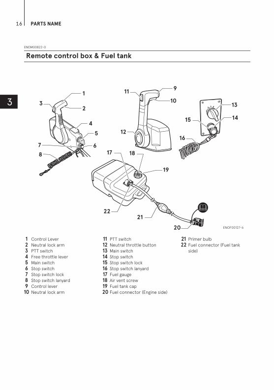
Remote control box & Fuel tank
1 Control Lever
2 Neutral lock arm
3 PTT switch
4 Free throttle lever
5 Main switch
6 Stop switch
7 Stop switch lock
8 Stop switch lanyard
9 Control lever
10 Neutral lock arm
11 PTT switch
12 Neutral throttle button
13 Main switch
14 Stop switch
15 Stop switch lock
16 Stop switch lanyard
17 Fuel gauge
18 Air vent screw
19 Fuel tank cap
20 Fuel connector (Engine side)
21 Primer bulb
22 Fuel connector (Fuel tank
side)
17
4
LABEL LOCATIONS
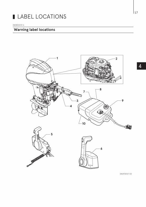
ENOM00019-A
Warning label locations
1
3
2
9
10
87
5
4
6
ENOF00127-D2
LABEL LOCATIONS18
4
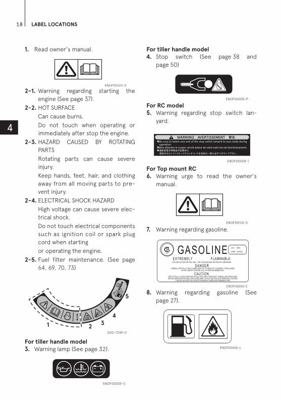
1. Read owner's manual.
2-1. Warning regarding starting the
engine (See page 37).
2-2. HOT SURFACE
Can cause burns.
Do not touch when operating or
immediately after stop the engine.
2-3. HAZARD CAUSED BY ROTATING
PARTS
Rotating parts can cause severe
injury.
Keep hands, feet, hair, and clothing
away from all moving parts to pre-
vent injury.
2-4. ELECTRICAL SHOCK HAZARD
High voltage can cause severe elec-
trical shock.
Do not touch electrical components
such as ignition coil or spark plug
cord when starting
or operating the engine.
2-5. Fuel filter maintenance. (See page
64, 69, 70, 73)
For tiller handle model
3. Warning lamp (See page 32).
For tiller handle model
4. Stop switch (See page 38 and
page 50)
For RC model
5. Warning regarding stop switch lan-
yard.
For Top mount RC
6. Warning urge to read the owner's
manual.
7. Warning regarding gasoline.
8. Warning regarding gasoline (See
page 27).
ENOF00120-0
FU
EL F
ILT
ER
GA
SO
LIN
EF
LOAT
WAT
ER
1 23
4
5
3UG-72181-0
ENOF00005-C
ENOF00005-P
ENOF00008-1
ENOF00120-0
ENOF00005-E
ENOF00005-L

LABEL LOCATIONS 19
4
9. Warning regarding gasoline (See
page 27).
10. Warning regarding gasoline (See
page 27).
ENOF00005-M
ENOF00005-F
LABEL LOCATIONS20
4
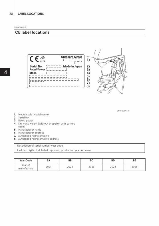
ENOM00019-B
1. Model code (Model name)2. Serial No.3. Rated power4. Dry mass weight (Without propeller, with battery
cable)5. Manufacturer name6. Manufacturer address7. Authorised representative8. Authorised representative address
CE label locations
ENOF00894-0
2)3)4)5)6)
1)
7)8)
Description of serial number year code
Last two digits of alphabet represent production year as below.
Year Code BA BB BC BD BE
Year of
manufacture2021 2022 2023 2024 2025

21
5
INSTALLATION
ENOM00024-A
ENOW00006-C
Gas assist type:
When taking outboard motor from pack-
age or removing outboard motor from the
boat, never release the lock lever. If the
lock lever is released, it will very easy for
the clamp bracket to spring up to the tilt-
ing direction because it is not fixed.
Before installing the outboard motor on
the boat, hang the outboard motor with
the hoist or equivalent device by attach-
ing the engine hanger to the outboard.
Use the hoist with allowable load is 250 kg
(550 lbs) or above.
ENOW00006-0
Most boats are rated and certified in terms
of their maximum allowable horsepower, as
shown on the boat’s certification plate. Do
not equip your boat with an outboard motor
that exceeds this limit. If in doubt, contact
your dealer.
Do not operate the outboard motor until it
has been securely mounted on the boat in
accordance with the instructions below.
ENOW00009-1A
Mounting the outboard motor without
following this manual can lead to unsafe
conditions such as poor maneuverability,
lack of control or fire.
Loose clamp screws and/or mounting
bolts can lead to the release or displace-
ment of the outboard motor, possibly
resulting in lost of control and/or serious
personal injury. Be sure that fasteners are
tightened to the specified torque (30 N·m
(3.0 kgf·m) 13 ft·lb). Check the fasteners
for tightness from time to time.
Be sure to use outboard mounting fasten-
ers included in the outboard motor pack-
age or their equivalents in terms of size,
material, quality and strength.
Outboard motor mounting must be per-
formed by trained service person(s)
using lift or hoist with sufficient capac-
ity.
1. Mounting the outboard motor on boat
WARNING
ENOF00840-0
WARNING
WARNING

INSTALLATION22
5
ENOM00025-0
Position ... Above keel linePlace the outboard motor in the center
of the boat's transom.
1. Center of boat2. Boat transom
ENOM00026-0
Transom matchingBe sure that the anti ventilation plate of
the outboard motor is 10–30 mm (0.4–
1.2 in) below the bottom of hull.
If the above condition cannot be met
due to the shape of the bottom of your
boat, please consult your authorized
dealer.
1. Bottom of hull2. Anti ventilation plate
ENOW00007-0
Before beginning the running test, check
that the boat with maximum capacity
loading floats on the water in a proper
attitude. Check the position of water sur-
face on the driveshaft housing. If the
water surface is near the bottom cowling,
in high waves, water may enter the engine
cylinders.
Incorrect outboard motor mounting
height or ex istence of under water
object(s), such as hull bottom design,
bottom surface conditions or underwa-
ter accessories, can cause water spray
possibly reaching the engine through an
opening of the bottom cowling during
cruising. Exposing the engine to such
conditions for extended periods can lead
to severe engine damage.
ENOM00830-C
Mounting the outboard motor
1. Set the outboard motor to appropri-
ate position.
2. Secure the clamp brackets to the
transom board using bolts, flat wash-
ers and nylon locking nuts.
1. Bolt (12 × 105)2. Washer (small diameter)3. Nylon locking nut4. Washer (large diameter) CAUTION
2
1
ENOF01141-0
1
2
10−30 mm(0.4−1.2 in)
ENOF00015-A3
1
4
2
ENOF00017-A

INSTALLATION 23
5
ENOW00008-B
Upper mounting bolts should be installed
with the bolt head at inside surface of the
transom. Mounting bolts installed with the
threaded end at the inside surface of the
transom can cause personal injury.
Tighten the bolts sufficiency, otherwise
falling down of outboard could be hap-
pened.
ENON00003-0
Note
Apply sealing agent, such as silicone
sealed between the bolts and the tran-
som board holes before tightening the
bolts.
Do not reuse nylon locking nut.
ENOM00029-A
ENOW00012-0
Battery electrolyte contains sulfuric acid
and thus is hazardous, causing a burn if it
comes in contact with your skin, or poison-
ous if swallowed.
Keep battery and electrolyte away from
reach of children
When handling the battery, be sure to:
Read all warnings shown on the battery
case
Prevent electrolyte from coming in con-
tact with any part of your body. Contact
can cause serious burn or, if it comes in
contact with your eye, loss of sight. Use
safety glasses and rubber gloves.
In case battery electrolyte comes in contact
with:
Skin, flush thoroughly with water.
Eye, flush thoroughly with water, and then
seek immediate medical treatment.
In case battery electrolyte is swallowed:
Seek immediate medical treatment.
ENOW00013-B
Battery generates explosive hydrogen gas.
Be sure to:
Charge the battery in a well-ventilated
place.
Place the battery away from any source of
fire, sparks and open flames such as
burners or welding equipment.
Do not smoke near the battery when the
battery is charging.
ENOW00014-0
Make sure that the battery leads do not
get stuck between the outboard motor
and boat when turning, etc.
The starter motor may fail to operate if
the leads are incorrectly connected.
Be sure to correctly connect the (+) and
(—) leads. If not, the charging system will
be damaged.
Do not disconnect the battery leads from
battery while the engine is operating, the
electrical parts could be damaged.
Always use a fully charged battery.
CAUTION
2. Battery installation
WARNING
351 (13.82)
251 (9.88)
125.5
25
3.5
(9
.98
)
51
(2.0
1)
56
(2
.2)
163.5 163.5
Ø12.5
Ø12.5
327 (12.87)
18 (
0.1
7)
125.5
ENOF00018-A
WARNING
CAUTION

INSTALLATION24
5
ENOW00015-0
Do not use a battery that is not recom-
mended. Use of a battery not recommended
can lead to poor performance of, and/or
damage to, the electrical system.
ENON00006-D
Note
Minimum battery requirements: 12v 70Ah/
20HR, 512 Cold Cranking Amps (CCA).
Larger capacity battery is required when it
is using freezing condition.
Recommend connecting only the engine
battery cables to the starting battery.
Specifications and features of batteries
vary among the manufacturers. Consult
the manufacturer for details.
* The battery should be purchased sepa-
rately and is not supplied with the out-
board motor.
1. Place the battery box in a convenient
position away from possible water
spray. Securely fasten both the box
and the battery so they do not shake
loose.
2. Connect the positive lead (+) to the
positive terminal (+) of the battery,
and then connect the negative lead
(—). When disconnecting the battery
always remove the negative lead (—)
first. After connecting the positive
terminal (+), securely place a cap on it
to prevent short circuits.
1. Battery cord (red)2. Battery cord (black)
ENOM00123-0
ENOW00085-A
Do not begin propeller removal and installa-
t ion proc e dure wi th spark plug caps
attached, shift in forward or reverse, main
switch at other than “OFF”, engine stop
switch lock attached to the switch, and
starter key attached, or engine could acci-
dentally start leading to serious personal
injury.
Disconnect battery cable if possible.
ENOW00085-0
Do not hold propeller with hand(s) when
loosening or tightening propeller nut. Put a
piece of wood block between propeller
blade and anti-ventilation plate to hold pro-
peller.
CAUTION
3. Propeller installation
WARNING
WARNING
2
1ENOF00022-1

INSTALLATION 25
5
ENOW00086-0
Do not install propeller without thrust
holder, or propeller boss could be dam-
aged.
Do not reuse split pin.
After installing split pin, spread the pin
apart to prevent it from falling out which
could lead to the propeller coming off
during operation.
Propeller must be selected that will allow
the engine to reach recommended maxi-
mum operating range during cruising.
Genuine propellers are listed on PROPEL-
LER TABLE of this manual (See page 89).
1. Remove the split pin, propeller nut
and washer.
2. Apply water proof grease to the pro-
peller shaft before installing a new
propeller.
3. Install the thrust holder, propeller
stopper, washer and propeller nut
onto the shaft.
1. Propeller2. Thrust holder3. Stopper4. Washer5. Nut6. Split pin
4. Tighten the propeller nut to specified
torque with holding the propeller by
wood block. And align one of grooves
to propeller shaft hole.
Propeller nut torque:
35 N·m (25 ft·lb, 3.5kgf·m)
5. Install a new split pin into the nut hole
and bend it.
CAUTION
Wide-open throttle rpm range
5000 – 6000 min-1 (rpm)
ENOF00084-B
12
34
6
5
ENOF00084-A
ENOF00084-B
INSTALLATION26
5
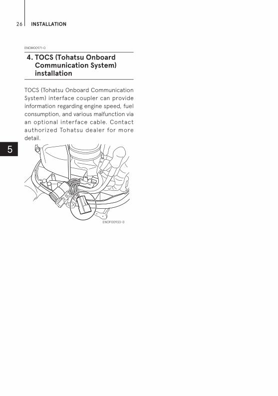
ENOM00971-0
TOCS (Tohatsu Onboard Communication
System) interface coupler can provide
information regarding engine speed, fuel
consumption, and various malfunction via
an optional interface cable. Contact
authorized Tohatsu dealer for more
detail.
4. TOCS (Tohatsu Onboard Communication System) installation
ENOF00933-0

27
6
PRE-OPERATING PREPARATIONS
ENOM00030-A
ENOW000017-0
Use of improper gasoline can damage your
engine. Engine damage resulting from the
use of improper gasoline is considered mis-
use of the engine, and damage caused
thereby will not be covered under the lim-
ited warranty.
ENOM00031-A
FUEL RATINGTOHATSU engines will operate satisfac-
torily when using a major brand of
unleaded gasoline meeting the following
specifications:
USA and Canada — having a posted
pump Octane Rating of 87 (R+M)/2 mini-
mum. Premium gasoline (92 [R+M]/2
Octane) is also acceptable. Do not use
leaded gasoline.
Outsi de US A and C ana da — Use
unleaded gasoline with declared octane
rating of 91 RON or over. Use of pre-
mium gasoline of 98 RON is also allowed.
ENOM00032-A
GASOLINES CONTAINING ALCOHOLThe fuel system components on your
TOHATSU engine will withstand up to
10% ethyl alcohol (hereinafter referred to
as the "ethanol"), content in the gasoline.
But even if the gasoline in your area con-
tains ethanol less than 10%, you should
be aware of certain adverse effects that
can occur. Increasing the percentage of
ethanol in the fuel can also worsen these
adverse effects. Some of these adverse
effects are caused because the ethanol
in the gasoline can absorb moisture from
the air, resulting in a separation of the
water/ethanol from the gasoline in the
fuel tank.
These may cause increased:
Corrosion of metal parts
Deterioration of rubber or plastic
parts
Fuel permeation through rubber fuel
lines
Starting and operating difficulties
If the use of gasoline containing alcohol
is inevitable, or presence of alcohol is
suspected in the gasoline, it is recom-
mended to add a filter that has water
separating capability, and check the fuel
system for leaks and mechanical parts
for corrosion and abnormal wear more
frequently.
And, in case any of such abnormality is
found, discontinue the use of such gas-
oline and contact our dealer immedi-
ately.
If the outboard motor will only be used
infrequently, please see the remarks on
fuel deterioration in the STORAGE chap-
ter (P 78) for additional information.
ENOW00020-1
When operating a TOHATSU engine on gaso-
line containing alcohol, storage of gasoline
in the fuel tank for long periods should be
avoided. Long periods of storage, create
unique problems. In cars, alcohol blend
fuels normally are consumed before they
can absorb enough moisture to cause trou-
ble, but boats often sit idle long enough for
1. Fuel handling
CAUTION
CAUTION

PRE-OPERATING PREPARATIONS28
6
phase separation to take place. In addition,
internal corrosion may take place during
storage if alcohol has washed protective oil
films from internal components.
ENOW00018-0
Fuel leakage can cause fire or explosion,
potentially leading to severe injury or loss of
life. Ever y fuel system par t should be
checked periodically, and especially after
long term storage, for fuel leak, change of
hardness of rubber, expansion and/or corro-
sion of metals. In case any indication of fuel
leakage or degradation of fuel part is found,
replace relevant part immediately before
continuing operation.
ENOM00043-B
ENOW00019-1
Do not fill the fuel tank over capacity. The
rise of gasoline temperature may cause gas-
oline to expand which, may leak through air
vent screw when it is open. Leaking gasoline
is a dangerous fire hazard.
ENOW00028-A
Consult an authorized dealer for details on
handling gasoline, if necessary.
Gasoline and its vapors are very flammable
and can be explosive.
When carrying a fuel tank containing gaso-
line:
Close the fuel tank cap and air vent screw
of fuel tank cap, or gasoline vapor will be
emitted through the air vent screw, cre-
ating a fire hazard.
Do not smoke.
When or before refueling:
Be sure to remove the static electricity
charged in your body before refueling.
The sparks due to static electricity may
cause explosion of flammable gasoline.
Stop the engine, and do not start the
engine during refueling.
Do not smoke.
Be careful not to overfill fuel tank. Wipe
up any spilled gasoline immediately.
When or before cleaning the gasoline tank:
Dismount fuel tank from the boat.
Place the fuel tank away from every
source of ignition, such as sparks or open
flames.
Do the work outdoors or in a well venti-
lated area.
Wipe off gasoline well immediately if
spilled.
After cleaning gasoline tank:
Wipe off gasoline well immediately if
spilled.
If the fuel tank is disassembled for clean-
ing, reassemble carefully. Imperfect
assembly may cause a fuel leak, possibly
leading to fire or explosion.
Dispose aged or contaminated gasoline in
accordance with local regulations.
ENOW00029-A
When opening fuel tank cap, be sure to fol-
low the procedure described below. Fuel
could blast out through the fuel tank cap in
case the cap is loosened by using another
procedure when internal pressure of fuel
tank is raised by heat from sources such as
sun light.
WARNING
2. Fuel filling
WARNING
WARNING WARNING
PRE-OPERATING PREPARATIONS 29
6
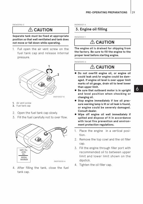
ENOW00946-0
Separate tank must be fixed at appropriate
position so that well ventilated and tank does
not move or fall down while operating.
1. Full open the air vent screw on the
fuel tank cap and release internal
pressure.
1. Air vent screw2. Fuel tank cap
2. Open the fuel tank cap slowly.
3. Fill the fuel carefully not to over flow.
4. After filling the tank, close the fuel
tank cap.
ENOM00037-A
ENOW00022-1
The engine oil is drained for shipping from
the factory. Be sure to fill the engine to the
proper level before starting engine.
ENOW00092-A
Do not overfill engine oil, or engine oil
could leak and/or engine could be dam-
aged. If engine oil level is over upper limit
marks of oil gauge, drain oil to level lower
than upper limit.
Be sure that outboard motor is in upright
and level position when checking or
changing oil.
Stop engine immediately if low oil pres-
sure warning lamp is lit or oil leak is found,
or engine could be severely damaged.
Consult dealer.
Wipe off engine oil well immediately if
spilled and dispose of it in accordance
with local fire prevention and environ-
ment protection regulations.
1. Place the engine in a vertical posi-
tion.
2. Remove the top cowl and the oil filler
cap.
3. Fill the engine through filler port with
recommended oil to between upper
limit and lower limit shown on the
dipstick.
4. Tighten the oil filler cap.
CAUTION
1
2
ENOF00027-B
SAFE FILL LEVEL 25 L
NIVEAU MAXIMUM
ENOF00030-A
3. Engine oil filling
CAUTION
CAUTION
PRE-OPERATING PREPARATIONS30
6
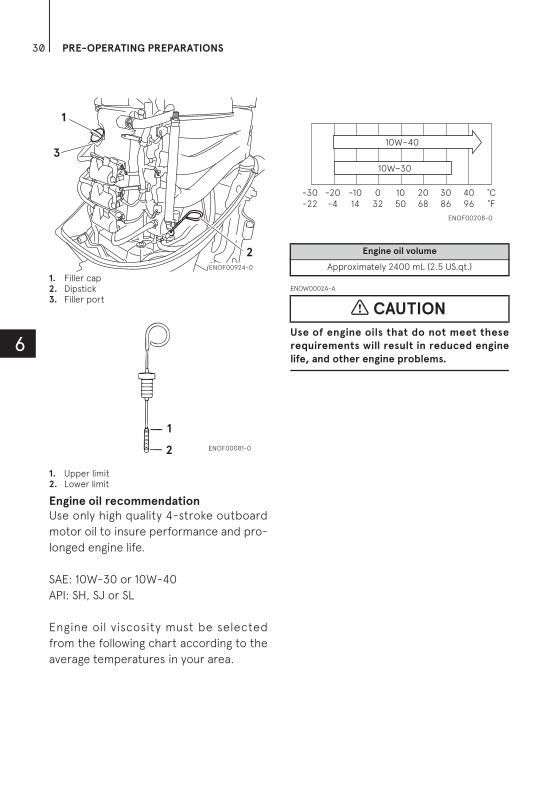
1. Filler cap2. Dipstick3. Filler port
1. Upper limit2. Lower limit
Engine oil recommendation
Use only high quality 4-stroke outboard
motor oil to insure performance and pro-
longed engine life.
SAE: 10W-30 or 10W-40
API: SH, SJ or SL
Engine oil viscosity must be selected
from the following chart according to the
average temperatures in your area.
ENOW0002A-A
Use of engine oils that do not meet these
requirements will result in reduced engine
life, and other engine problems.
1
2
3
ENOF00924-0
2
1
ENOF00081-0
Engine oil volume
Approximately 2400 mL (2.5 US.qt.)
CAUTION
10W−40
10W−30
˚C˚F
4096
3086
2068
1050
032
-1014
-20-4
-30-22
ENOF00208-0

PRE-OPERATING PREPARATIONS 31
6
]ENOM00033-A
Your new outboard motor and lower unit
require break-in for the moving compo-
nents according to the conditions
described in the following time table.
Please refer to ENGINE OPERATION sec-
tion (See page 36) to learn how to cor-
rectly start and operate the outboard
motor.
ENOW00024-A
Do not operate the outboard motor in
closed area or area with no forced ventila-
tion.
Exhaust gas emitted by this outboard motor
contains carbon monoxide that will cause
death if inhaled continuously. Inhaling the
gas initially causes symptoms such as feeling
of sickness, drowsiness and headache.
During operation of the outboard motor:
Keep peripheral area well ventilated.
Always attempt to stay on the windward
side of emission.
ENOW00023-1
Operating the outboard motor without
break-in can shorten life.
If any abnormality is experienced during the
break-in:
Discontinue the operation immediately.
Have the dealer check the product and
take proper action(s) if necessary.
ENON00008-1
Note
Run at varied speed less than specified
engine speed during the break-in peri-
ods.
Break-in must be conduct under load
in the water with propeller installed
and in-gear.
4. Break-In
DANGER
CAUTION
1–10 min 10 min – 2 hrs 2–3 hrs 3–10 hrs After 10 hrs
Throttle Position IdleLess than 1/2
throttle
Less than 3/4
throttle3/4 throttle
Full throttle
available
SpeedApprox. 3000
min-1 (rpm) max
Full throttle run
allowed for 1
min every 10
min
Approx. 4000
min-1 (rpm). Full
throttle run
allowed for 2
min every 10
min

PRE-OPERATING PREPARATIONS32
6
ENOM00039-0
If outboard motor encounters an abnor-
mal condition of fault, the warning buzzer
will emit a continuous beep or intermit-
tent short beeps and the warning lamp
(LED) will synchronize with the buzzer and
engine speed will be limited (engine will
not be stopped).
See next page for conditions which will
lead to an abnormal condition or fault.
ENOM00040-A
Location of warning buzzer and lamp
Warning buzzer
RC model: Located inside the remote
control.
Tiller handle model: Located in the tiller
handle.
Warning lamp (LED)
RC model: Located in the tachometer.
Tiller handle model: Located on the tiller
handle
ENON00009-A
Note
Warning lamp for optional tachometer will
synchronize with the warning lamp for
engine side.
1. Warning lamp
1. Warning lamp
5. Warning system1
ENOF00851-0
1
ENOF00852-1

PRE-OPERATING PREPARATIONS 33
6
ENOM00041-A
Warning indicators, faults and remedy
High speed ESG (Electronic Safety Governor)
High speed ESG is a device to prevent over revolution of the engine. If the load to the engine becomes light for
some reason, it runs at a higher speed than the usual. In such the case, the buzzer sounds and the ESG is
activated not to ignite the spark plug, therefore, the engine speed varies and be controlled under 6200 min-1
(rpm).
Low speed ESG
Low speed ESG is a device to prevent the engine from getting damage. If the engine has problems regarding
cooling water, oil pressure, and sensors, the low speed ESG is activated not to ignite the spark plug, and disable
fueling therefore, the engine speed varies and be controlled under 3000 min-1 (rpm).
Warning indicators
ESG Description of faults
or notice RemarkRem-edy
Sound
A lamp
B lamp
C lamp
Continu-ous
ON ON ON - Normal system test when key on
1 second
Continu-ous - - -
High speed ESG
Engine speed exceeds maximum
allowable RPM
Approx. 6,200 min-1 (rpm)
1
Continu-ous ON - -
Low speed ESG
Low oil pressure 2
Continu-ous - Flash-
ing -Low
speed ESG
Cooling water temp. is highOver
85°C/185°F3
Continu-ous
Flash-
ingFlash-
ingFlash-
ing
Forced ideling
Cooling water temp. is abnormally high
Over 140°C/284°F
3
- - - Flash-ing
- Battery voltage is low Engine is stopped under 9V
4
-Flash-
ingFlash-
ingFlash-
ing
Low speed ESG
Malfunction of sensor 5
- Flash-ing
Flash-ing
Flash-ing
- Malfunction of electrical part
5
-Flash-
ing - - -
Inform the recommended timing of engine oil replacement (every
100hrs.)
“A lamp” ON 1 sec. and OFF 9 sec. 6
One beep - - - -Lowest idling speed of variable idling system
Two beep - - - -Highest idling speed of variable idling system

PRE-OPERATING PREPARATIONS34
6
Remedy
1. Reduce the throttle to less than half
opening, and move to safe place
quickly, and stop the engine.
Check the propeller for bent or dam-
aged blades.
Consult an authorized dealer if engine
shows the same result even after
replacing propeller with new one.
2. Move to safe place quickly, and stop
the engine.
Check the engine oil level, and add
engine oil if necessary.
Consult your dealer if the engine oil
level is too low or too high.
3. Move to safe place quickly, and check
the discharge of cooling water from
the water check port at idle speed
and stop engine.
Remove any foreign matter on the
gear case and propeller if necessary.
Consult an authorized dealer if no
discharge of cooling water.
4. Charge or replace the battery.
5. Consult an authorized dealer.
6. Replace the engine oil (See page 70)
and reset the indicator (See page 34).
ENOW00025-A
Low speed ESG ON: Engine speed will be
limited to 2800 min-1 (rpm), however you
should not continue to run engine.
High speed ESG ON: Engine speed will be
limited to 6200 min-1 (rpm) and engine will
run rough until throttle is reduced.
ENOM00870-0
Engine oil replacement indicator function reset method
As for "Engine oil replacement indicator
function", informing the appropriate
timing of engine oil replacement by blink-
ing of the lamp, when beyond 100 hours
operating.
1. Be certain the safety lanyard is
installed. Turn the key to the 'on'
position and after the 'beep' pull the
safety lanyard off.
2. Within 5-10 seconds, Pull the red
knob on the safety switch out and
release.
CAUTION
1 Second
ENOF00853-0
ENOF00854-0

PRE-OPERATING PREPARATIONS 35
6
3. Wait 5-10 seconds and pull the red
knob out and release.
4. Within 5-10 seconds you will here 3
beeps to inform you that you have
successfully reset the system.
5. Turn the ley to the 'off' position and
replace the safety lanyard lock.
The engine oil replacement indicators
function operates again after 100 hours
operation from reset this function.
ENOF00854-0
ENOF00856-0
36
7
ENGINE OPERATION
ENOM00042-0
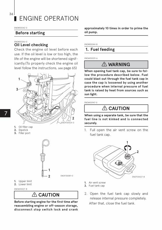
ENOM00246-0
Oil Level checkingCheck the engine oil level before each
use. If the oil level is low or too high, the
life of the engine will be shortened signif-
icantly.(To properly check the engine oil
level follow the instructions, see page 65)
1. Oil filler cap2. Dipstick3. Filler port
1. Upper limit2. Lower limit
ENOW00027-B
Before starting engine for the first time after
reassembling engine or off-season storage,
disconnect stop switch lock and crank
approximately 10 times in order to prime the
oil pump.
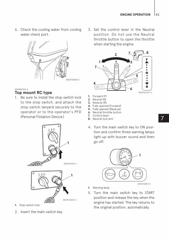
ENOM00044-B
ENOW00029-A
When opening fuel tank cap, be sure to fol-
low the procedure described below. Fuel
could blast out through the fuel tank cap in
case the cap is loosened by using another
procedure when internal pressure of fuel
tank is raised by heat from sources such as
sun light.
ENOW00947-0
When using a separate tank, be sure that the
fuel line is not kinked and is connected
securely.
1. Full open the air vent screw on the
fuel tank cap.
1. Air vent screw2. Fuel tank cap
2. Open the fuel tank cap slowly and
release internal pressure completely.
After that, close the fuel tank.
Before starting
CAUTION
1
2
3
ENOF00924-0
2
1
ENOF00081-0
1. Fuel feeding
WARNING
CAUTION
1
2
ENOF00027-B

ENGINE OPERATION 37
7
3. Connect the fuel connector to the
engine and fuel tank.
1. Fuel connector2. Push3. Insert
1. Pull2. Insert
4. Squeeze primer bulb until it becomes
stiff to feed fuel to vapor separator.
Direct arrow mark upward when
priming.
1. Engine side2. Fuel tank side
Do not squeeze primer bulb with engine
running or when the outboard motor is
tilted up. Otherwise, fuel could overflow.
ENOM00045-A
ENOW00958-0
Do not remove or install the top cowl
after the engine has been started.
The exposed rotating engine parts or
moving parts cause serious injury.
ENOW00959-0
The top cowl must be installed while the
engine running except in an emergency. If
the top cowl is not installed correctly, water
splash can damage the engine.
ENOW00036-A
When the engine is started in the test tank,
to avoid over heating and water pump dam-
age, be sure the water level is at least 10 cm
(4 in.) above the anti ventilation plate.
Run the engine only at idling.
And be sure to remove the propeller, when
starting the engine in the test tank. (See
page 75)
Run the engine only at idling.
1
2233
ENOF00860-A
1
2
ENOF00861-A
1
2ENOF00862-0
2. Starting the engine
WARNING
CAUTION
CAUTION

ENGINE OPERATION38
7
1. Test tank2. Water3. Over 10 cm (4 in.)
ENOW00036-0
Be sure to stop engine immediately if cooling
water check port is not discharging water,
and check if cooling water intake is blocked.
Operating engine could lead to overheating
potentially leading to engine damage. Con-
sult an authorized dealer if the cause cannot
be found.
ENOW00032-A
Do not hold turning starter motor more than
5 seconds, or the battery may be consumed,
potentially making the engine star ting
impossible and/or damaging the starter.
If cranking over 5 seconds fails to start
engine, return main switch to “ON”, and
crank engine again after 10 seconds or more.
Do not try to crank after engine has started.
This model is provided with start in gear
protection.
ENON00010-0
Note
Start-in-gear protection prevents engine
from starting at other than neutral shift.
In-gear starting of engine will move the
boat immediately, potentially leading to
falling down or causing passenger(s) to be
thrown overboard.
Tiller handle type1. Be sure to install the stop switch lock
to the stop switch, and attach the
stop switch lanyard securely to the
operator or to the operator's PFD
(Personal Flotation Device.)1.
1. Stop switch lock2. Main switch key
2. Insert the main switch key.
3. Set the control lever in the Neutral
position.
1. Shift lever
CAUTION
CAUTION
1
3
2
ENOF00863-0
12
ENOF00864-1
R
N
F1
ENOF00865-2

ENGINE OPERATION 39
7
ENOW00031-0
If the engine starts in gear, do not use it.
Contact an authorized dealer.
4. Set the throttle grip to START posi-
tion.
1. Throttle grip
5. Turn the main switch key to ON posi-
tion and confirm three warning lamps
light up with buzzer sound and then
go off.
6. Turn the main switch key to START
position and release the key when the
engine has started. The key returns to
the original position, automatically.
1. Main switch key2. Warning lamp
ENOW00032-1
Do not hold turning starter motor more than
5 seconds, or the battery may be consumed,
potentially making the engine star ting
impossible and/or damaging the starter.
If cranking over 5 seconds fails to start
engine, return main switch to “ON”, and
crank engine again after 10 seconds or more.
7. Check the cooling water from cooling
water check port.
CAUTION
1
ENOF00866-2
R
N
F
1
2
ENOF00867-2
CAUTION
ENOF00868-0

ENGINE OPERATION40
7
Side mount RC type1. Be sure to install the stop switch lock
to the stop switch, and attach the
stop switch lanyard securely to the
operator or to the operator's PFD
(Personal Flotation Device.)
1. Stop switch lock
2. Insert the main switch key.
3. Set the control lever in the Neutral
position. Do not raise the free throt-
tle lever when starting the engine.
1. Neutral (N)2. Control lever3. Fully opened (Forward)4. Fully opened (Reverse)5. Free throttle lever6. Main switch key7. Stop switch
4. Turn the main switch key to ON posi-
tion and confirm three warning
lamps light up with buzzer sound and
then go off.
1. Warning lamp
5. Turn the main switch key to START
position and release the key when
the engine has star ted. The key
returns to the original position,
automatically.
1. ON2. START3. OFF
ENON00035-A
Note
The free throttle lever can not be raised
when the control lever shift is in Forward
or Reverse.
1
ENOF00869-1
NRF
1 2
3
4
5
6
7ENOF00870-1
1
ENOF00851-0
1
2
3
ENOF00871-1
ENGINE OPERATION 41
7
6. Check the cooling water from cooling
water check port.
ENOM00974-A
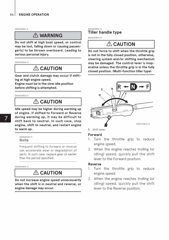
Top mount RC type1. Be sure to install the stop switch lock
to the stop switch, and attach the
stop switch lanyard securely to the
operator or to the operator's PFD
(Personal Flotation Device.)
1. Stop switch lock
2. Insert the main switch key.
3. Set the control lever in the Neutral
position. Do not use the Neutral
throttle button to open the throttle
when starting the engine.
1. Forward (F)2. Neutral (N)3. Reverse (R)4. Fully opened (Forward)5. Fully opened (Reverse)6. Neutral throttle button7. Control lever8. Neutral lock arm
4. Turn the main switch key to ON posi-
tion and confirm three warning lamps
light up with buzzer sound and then
go off.
1. Warning lamp
5. Turn the main switch key to START
position and release the key when the
engine has started. The key returns to
the original position, automatically.
ENOF00868-0
1
ENOF00936-1
1
ENOF02409-0
N
RF
1
7
4
8
5
6
7
2
3
R
F
N
ENOF00937-0
1
ENOF00851-0

ENGINE OPERATION42
71. ON2. START3. OFF
ENON00939-0
Note
The neutral throttle button can not be
push-in when the control lever shift is in
Forward or Reverse.
6. Check the cooling water from cooling
water check port.
ENOM00042-A
Emergency startingENOW00099-A
When the emergency starter rope is used for
starting engine;
Start in gear protection does not work. Be
sure to shift is at neutral position. Other-
wise the engine will move the boat imme-
diately and cause personal injury.
Be careful that your clothes or other
items do not get caught in the rotating
engine parts.
To prevent accident and injury by rotating
parts, do not re-attach flywheel cover
and the top cowl after the engine has
been started.
Do not pull starter rope if any bystander is
b e hin d. T h e a c t i on c an in jur e th e
bystander.
Attach engine stop switch lanyard to
clothing or any part of body like arm
before starting engine.
1. Remove the top cowl.
3
1
2
ENOF00938-1
3
1
2
ENOF02410-0
ENOF00868-0
WARNING
ENOF00872-0

ENGINE OPERATION 43
7
2. Remove the flywheel cover.
1. Bolt2. Rubber grommet
3. Insert the knotted end of the starter
rope into the notch in the flywheel
and wind the rope around the fly-
wheel several turns clockwise.
4. Tie a loop in the another end of the
emergency starter rope and attach
socket wrench that is included in the
tool kit.
ENOW00860-0
Be sure to keep the harness away from the
rotation parts.
1. Harness
5. Be sure to install the stop switch lock
to the stop switch, and attach the
stop switch lanyard securely to the
operator or to the operator's PFD
(Personal Flotation Device.)
6. Set the control lever in the Neutral
position.
7. Pull the starter handle slowly until you
feel engagement, keep pulling till you
feel less resistance. Then pull it
quickly.
8. After engine starts, do not reinstall
flywheel cover and top cowl.
ENOM00043-A
ENOW00932-0
Be sure to check that cooling water is com-
ing out of the cooling water check port
during warm up.
Warm the engine at low engine speeds
for about
3 minutes : above 5°C (41°F)
5 minutes at 2000 min-1 (rpm) : blow 5°C
(41°F)
CAUTION
2
2
1
ENOF00873-0
ENOF00874-0
3. Warming up the engine
CAUTION
1
ENOF00875-0

ENGINE OPERATION44
7
This allows the lubricating oil to circulate
to all parts of the engine. Operating the
engine without warm up shortens the
engine's life.
ENOM00044-0
Engine speedsIdling speed after warming up.
Remark: In case of cold engine starting,
idling speed is increased about 400 min-1
(rpm) for several minutes.
ENOM00972-0
Free throttle lever (Side mount RC
type)ENOW00956-0
Keep the free throttle lever fully closed-
position when start the engine.
The free throttle lever is inoperative
unless the control lever is in neutral.
Also, the control lever is inoperative
unless the free throttle lever is returned
to the fully-closed position.
The free throttle lever is for warm-up
operation.(Not required for engine start-
ing) With the control lever in neutral,
move the free throttle lever upward to
open the throttle.
1. Fully-open2. Fully-closed
ENOM00973-0
Neutral throttle button (Top
mount RC type)ENOW00957-0
The control lever does not operate unless
the neutral lock arm is pulled.
The neutral throttle button is for warm-
up operation. (Not required for engine
starting) When the control lever is in
neutral, push and hold the neutral throt-
tle button. While holding the button,
move the lever forward to throttle up the
engine.
When the control lever is returned to the
neutral position, the button will reset
automatically.
1. Neutral throttle button2. Forward
Clutch in (In gear) Clutch off (Out of gear)
850 min-1 (rpm) 850 min-1 (rpm)
CAUTION
ENOF00868-0
CAUTION
1
2
ENOF00934-0
1
2
ENOF00935-0

ENGINE OPERATION 45
7
ENOM00880-0
Trolling engine speed control
function If the main switch key is pressed for 1
(one) second during idling or trolling
operation, engine revolution change.
Each time the main switch key is pressed
in the above manner, engine speed
changes as follows.
Starting
850 min-1 (rpm) 750 min-1 (rpm) 650 min-1 (rpm)
950 min-1 (rpm) 850 min-1 (rpm) 750 min-1 (rpm)
Buzzer short sounded one time, when set
to 650 min-1 (rpm) engine speed, and tells
the lowest engine speed was set.
Buzzer short sounded twice, when set to
950 min-1 (rpm) engine speed, and tells
the highest engine speed was set.
Reset the engine speed when after
engine restarted and or engine speed is
above 3,000 min-1 (rpm), and then trolling
engine speed to be 850 min-1 (rpm) as
standard.
In addition, this function does not oper-
ate when battery voltage is lower than
specified, set engine idle and trolling
engine speed to 850 min-1 (rpm) auto-
matically.
ENOM00046-A
ENOW00037-0
Before shifting into forward or reverse, make
sure that boat is properly moored and out-
board motor can be steered fully to the right
and left. Make sure that no swimmer(s) is
ahead or astern of the boat.
ENOW00038-A
Attach other end of emergency stop
switch lanyard to the operator's PFD (Per-
sonal Flotation device) or arm and keep it
attached during cruising.
Do not attach the tether to a part of
clothing that can be torn easily when
pulled.
Arrange the tether so that will not be
caught by any object when pulled.
Be careful not to pull the tether acciden-
tally during cruising. Unintentional stop of
engine can cause loss of control of out-
board motor. Rapid loss of engine power
can lead to falling down or causing pas-
senger(s) to be thrown overboard.
ENOW00042-0
Do not shift into Reverse during planing,
or control will be lost leading to serious
personal injury, boat may swamp, and/or
hull may be damaged.
Do not shift into Reverse during cruising,
or control may be lost, falling down or
causing passenger(s) to be thrown over-
board. Leading to serious personal injury,
and steering system and/or shifting
mechanism may be damaged.
ON
1second
ENOF00876-0
4. Forward, reverse, and acceleration
WARNING
WARNING
WARNING
ENGINE OPERATION46
7
ENOW00861-0
Do not shift at high boat speed, or control
may be lost, falling down or causing passen-
ger(s) to be thrown overboard. Leading to
serious personal injury.
ENOW00862-0
Gear and clutch damage may occur if shift-
ing at high engine speed.
Engine must be in the slow idle position
before shifting is attempted.
ENOW00863-0
Idle speed may be higher during warming up
of engine. If shifted to Forward or Reverse
during warming up, it may be difficult to
shift back to neutral. In such case, stop
engine, shift to neutral, and restart engine
to warm up.
ENON00014-0
Note
Frequent shifting to forward or reverse
can accelerate wear or degradation of
parts. In such case, replace gear oil earlier
than the period specified.
ENOW00864-0
Do not increase engine speed unnecessarily
when the shift is in neutral and reverse, or
engine damage may occur.
ENOM00890-A
Tiller handle typeENOW00865-0
Do not force to shift when the throttle grip
is not in the fully closed position, otherwise,
steering system and/or shifting mechanism
may be damaged. The control lever is inop-
erative unless the throttle grip is in the fully
closed position. (Multi-function tiller type)
1. Shift lever
Forward
1. Turn the throttle grip to reduce
engine speed.
2. When the engine reaches trolling (or
idling) speed, quickly pull the shift
lever to the Forward position.
Reverse
1. Turn the throttle grip to reduce
engine speed.
2. When the engine reaches trolling (or
idling) speed, quickly pull the shift
lever to the Reverse position.
WARNING
CAUTION
CAUTION
CAUTION
CAUTION
R
N
F1
ENOF00865-D

ENGINE OPERATION 47
7
AccelerationENOW00867-0
Sudden acceleration and deceleration may
cause passenger(s) to be thrown overboard
or falling down.
Open throttle grip gradually.
1. Throttle grip
ENOM00900-0
Side mount RC typeENOW00867-0
Sudden acceleration and deceleration may
cause passenger(s) to be thrown overboard
or falling down.
1. Forward (F)2. Neutral (N)3. Reverse (R)4. Fully opened (Forward)5. Fully opened (Reverse)6. Free throttle lever7. Control lever8. Neutral lock arm
Forward
1. Quickly push the control lever to the
Forward (F) position 32°, where the
gear is connected, while lifting up on
the neutral lock arm located under
the control lever grip.
2. Further forward motion will open the
throttle.
Reverse
1. Quickly pull the control lever to the
Reverse (R) position at 32°, where the
gear is connected, while lifting up on
the neutral lock arm located under
the control lever grip.
2. Further rearward motion will open
the throttle.
WARNING
WARNING
1
ENOF00878-2
NRF
2 7
4
5
6
78
1 3
ENOF00877-1

ENGINE OPERATION48
7
AccelerationENOW00867-0
Sudden acceleration and deceleration may
cause passenger(s) to be thrown overboard
or falling down.
Open throttle grip or control lever gradu-
ally.
1. Control lever
ENOM00975-0
Top mount RC typeENOW00867-0
Sudden acceleration and deceleration may
cause passenger(s) to be thrown overboard
or falling down.
1. Forward (F)2. Neutral (N)
3. Reverse (R)4. Fully opened (Forward)5. Fully opened (Reverse)6. Neutral throttle button7. Control lever8. Neutral lock arm
Forward
1. Quickly push the control lever to the
Forward (F) position 35°, where the
gear is connected, while lifting up on
the neutral lock arm located under
the control lever grip.
2. Further forward motion will open the
throttle.
Reverse
1. Quickly pull the control lever to the
Reverse (R) position at 35°, where the
gear is connected, while lifting up on
the neutral lock arm located under
the control lever grip.
2. Further rearward motion will open
the throttle.
AccelerationENOW00867-0
Sudden acceleration and deceleration may
cause passenger(s) to be thrown overboard
or falling down.
Open throttle grip or control lever gradu-
ally.
ENOM00049-A
ENOW00868-0
Be careful not to remove engine stop switch
lanyard from engine accidentally while boat
is running. Sudden stop of engine can cause
loss of steering control. It can also cause
loss of boat speed, possibly leading the
WARNING
WARNING
NRF
1
ENOF00879-2
N
RF
1
7
4
8
5
6
7
2
3
R
F
N
ENOF00937-0
WARNING
5. Stopping the engine
WARNING

ENGINE OPERATION 49
7
crew(s) and or objects on the boat to be
thrown forward due to inertial force.
Tiller handle type1. Turn the throttle grip to the slow
position.
1. Throttle grip2. Shift lever3. Main switch key
1. Turn the throttle grip to the slow
position.
2. Put the shift lever in the Neutral posi-
tion.
Run the engine for 2-3 minutes at
idling speed for cooling down if it has
been running at full speed.
3. Turn the main switch key to the OFF
position.
Side mount RC type1. Put the control lever in the Neutral
position and run the engine for 2-3
minutes at idling speed for cooling
down if it has been running at full
speed.
1. Control lever2. Main switch key
2. Turn the main switch key to the OFF
position.
1. ON2. START3. OFF
ENOW00869-0
After stopping the engine:
Close the air vent screw on the fuel tank
cap.
Disconnect the fuel connector of the
engine and the fuel tank.
1
ENOF00866-2
R
N
F
3
21
ENOF00880-C
WARNING
NRF
1
2
ENOF00881-1
1
2
3
ENOF00871-1

ENGINE OPERATION50
7
Disconnect the battery cord, after each
use.
ENOM00975-0
Top mount RC type1. Put the control lever in the Neutral
position and run the engine for 2-3
minutes at idling speed for cooling
down if it has been running at full
speed.
1. Control lever
2. Turn the main switch key to the OFF
position.
2. Main switch key3. ON4. START5. OFF
ENOW00869-0
After stopping the engine:
Close the air vent screw on the fuel tank
cap.
Disconnect the fuel connector of the
engine and the fuel tank.
Disconnect the battery cord, after each
use.
Emergency engine stopping
Press the emergency stop switch or
remove stop switch lock to stop the
engine.
1. Stop switch2. Stop switch lock
1. Stop switch2. Stop switch lock
N
RF1
R
F
N
ENOF00939-0
5
3
42
ENOF00938-A1
5
3
4
2
ENOF02411-0
WARNING
R
N
F
1
2
ENOF00883-C
2
1
ENOF00869-A

ENGINE OPERATION 51
71. Stop switch2. Stop switch lock
ENOM00910-0
Spare emergency stop switch lock
A spare emergency stop switch lock is
provided in the tool bag.
When used as described, the emergency
stop switch clip and emergency stop
switch lanyard system stops the engine if
the operator falls away from the controls.
When an operator falls into water, be
sure to use emergency stop switch lock
of the spare.
Be sure to confirm the spare stop switch
lock is in the tool bag before begin to
operate.
ENOM00920-0
ENOW00870-0
Sudden steering may cause passenger(s) to
be thrown overboard or falling down.
Tiller handle typeRight turn
Move the tiller handle to the left
Left turn
Move the tiller handle to the right.
Remote control typeRight turn
Turn the steering wheel to the right.
Left turn
Turn the steering wheel to the left.
1
2
ENOF00938-B1
1
2
ENOF02412-0
ENOF00891-0
6. Steering
WARNING
ENOF00892-0
ENOF00893-0

ENGINE OPERATION52
7
ENOM00050-0
ENOW00043-0
Do not put hand or finger in between out-
board motor body and clamp bracket
when adjusting trim angle to prevent
injury in case the outboard motor body
falls.
Unsuitable trim position can cause loss of
control of boat. When testing a trim posi-
tion, run boat slow initially to see if it can
be controlled safely.
ENOW00044-0
Excessive trim up or down may lead to unsta-
ble boat operation, potentially causing the
steering difficulty that leads to accident
during cruising.
Do not cruise at high speed if improper
trim position is suspected. Stop the boat
and readjust trim angle before continuing
cruise.
For outboard motor model with PTT
switch on the bottom cowl, do not oper-
ate the switch during cruising, or control
of boat may be lost.
The trim angle of the outboard motor can
be adjusted to suit the transom angle of
the hull, and load conditions. Choose an
appropriate trim angle that will allow the
anti-ventilation plate to run parallel to
the water surface during operation.
ENOM00052-0
Proper trim angle
The position of the thrust rod is correct if
the hull is horizontal during operation.
1. Perpendicular to the water surface
ENOM00053-0
Improper trim angle (bow rises too high)
Set the thrust rod lower if the bow of the
boat rises above horizontal.
ENOM00054-0
Improper trim angle (bow dips into the water)
Set the thrust rod higher if the bow of
the boat is below horizontal.
7. Trim angle
WARNING
WARNING
1
ENOF00051-1
ENOF00052-0
ENOF00053-0
ENGINE OPERATION 53
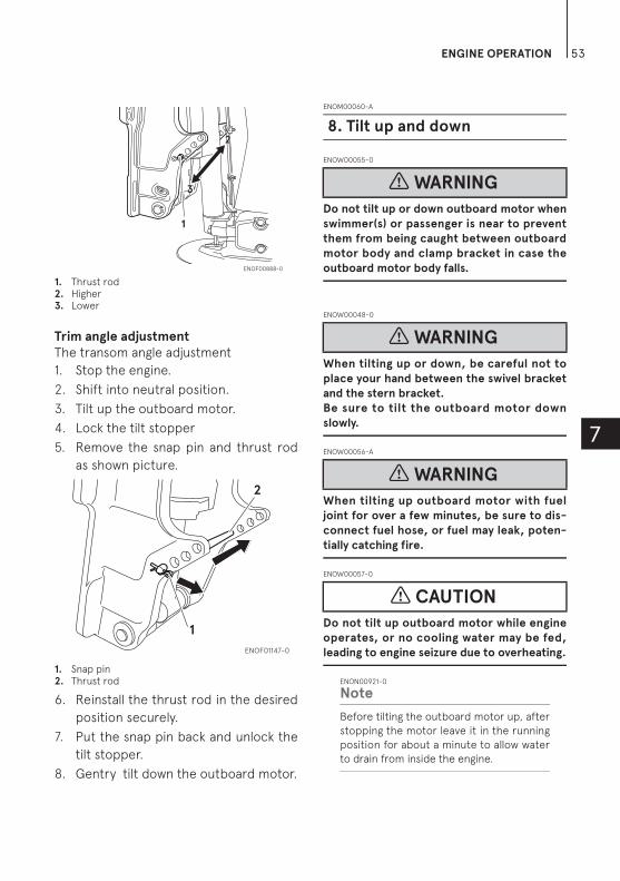
7
1. Thrust rod2. Higher3. Lower
Trim angle adjustment
The transom angle adjustment
1. Stop the engine.
2. Shift into neutral position.
3. Tilt up the outboard motor.
4. Lock the tilt stopper
5. Remove the snap pin and thrust rod
as shown picture.
1. Snap pin2. Thrust rod
6. Reinstall the thrust rod in the desired
position securely.
7. Put the snap pin back and unlock the
tilt stopper.
8. Gentry tilt down the outboard motor.
ENOM00060-A
ENOW00055-0
Do not tilt up or down outboard motor when
swimmer(s) or passenger is near to prevent
them from being caught between outboard
motor body and clamp bracket in case the
outboard motor body falls.
ENOW00048-0
When tilting up or down, be careful not to
place your hand between the swivel bracket
and the stern bracket.
Be sure to tilt the outboard motor down
slowly.
ENOW00056-A
When tilting up outboard motor with fuel
joint for over a few minutes, be sure to dis-
connect fuel hose, or fuel may leak, poten-
tially catching fire.
ENOW00057-0
Do not tilt up outboard motor while engine
operates, or no cooling water may be fed,
leading to engine seizure due to overheating.
ENON00921-0
Note
Before tilting the outboard motor up, after
stopping the motor leave it in the running
position for about a minute to allow water
to drain from inside the engine.
1
2
3
2
3
ENOF00888-0
1
2
ENOF01147-0
8. Tilt up and down
WARNING
WARNING
WARNING
CAUTION

ENGINE OPERATION54
7
ENOM00065-A
Gas assist typeENOW00871-0
When taking outboard motor from package
or removing outboard motor from the boat,
never release the lock lever. If the lock lever
is released, it will very easy for the clamp
bracket to spring up to the tilting direction
because it is not fixed.
ENOW00070-0
Ne ver at tempt to disassemble shock
absorber of gas assist tilt system. It is dan-
gerous because high pressure gas is included
in the shock absorber.
ENOM00066-A
Tilt up
1. Move (UP) lock lever to “Free” posi-
tion.
2. Fully tilt up the outboard motor.
3. While keeping the outboard motor in
full tilt up position, move, (DOWN)
lock lever to “Lock” position.
4. For safety, set the tilt stopper into the
set- up position, although the out-
board motor is kept in the tilt up
position after the lock lever is moved
(DOWN) to “Lock” position.
ENOM00067-A
Tilt down
1. Move (UP) lock lever to “Free” posi-
tion.
2. Release the tilt stopper from the set-
up position while slightly tilting up
outboard motor.
3. Release outboard motor down to
thrust rod.
4. Move (DOWN) lock lever to “Lock”
position after the outboard motor is
completely tilted down.
1. Free position2. Lock position
1. Tilt stopper
ENOM00069-A
Power Trim & Tilt typeTilt up
1. Operate the Power Trim & Tilt switch
and tilt the outboard motor up.
2. Lock the tilt with the Tilt stopper after
the outboard motor has been tilted
up
Tilt down
1. Release the tilt stopper from the set-
up position while slightly tilting up
outboard motor.
WARNING
WARNING
11
22
ENOF00064-A
1 ENOF00889-0

ENGINE OPERATION 55
7
2. Operate the Power Trim & Tilt switch
and tilt the outboard motor down
until the motor touches to the thrust
rod.
1. Tilt stopper
The outboard motor can also be tilted up
and down using the switch provided
under the bottom cowl.
It is possible to tilt up or down in spite of
main switch “ON” or “OFF”.
ENOM00940-0
Manual relief valve
If the battery is dead, and the power trim
& tilt switch thus inoperative, open the
manual valve completely in the Manual
direction. This will allow manual tilting of
the outboard motor.
ENOW00872-0
Make sure the manual relief valve is closed
before operating the outboard motor. If the
manual relief valve is not closed, the out-
board motor will tilt up when operated in
reverse.
ENOW00873-0
Before opening the manual relief valve, make
sure nobody is under the outboard motor. If
the outboard motor is in the tilted up posi-
tion, it will tilt down suddenly if the manual
relief valve is loosened in the "Manual"
direction.
UP
DN
ENOF00067-2
UP
DN
ENOF00941-0
UP
DNENOF00067-B
ENOF02437-0
DN UP
1 ENOF00889-0
WARNING
WARNING
ENOF00891-B

ENGINE OPERATION56
7
1. Power2. Manual
Manual relief valve specified torque:
1.8 N-m (1.4 ft-lb, 0.18 kgf-m)
ENOM00068-A
ENOW00051-0
During shallow water operation, be careful
not to place your hand between the swivel
bracket and the clamp bracket. Be sure to
tilt the outboard motor down slowly.
ENOW00053-0
While in shallow water drive position, do not
operate the outboard motor in Reverse.
Operate the outboard motor at slow speed
and keep the cooling water intake sub-
merged.
ENOW00054-0
Do not overtilt outboard motor when driving
shallow water, or air may be sucked through
water inlet, potentially leading to engine
overheating.
1. Water inlet
ENOM00880-A
Gas assist type1. Move (UP) lock lever to “Free” posi-
tion. Tilt up outboard motor into
desired shallow water running. While
keeping the outboard motor in the
desired shallow water running posi-
tion, move (DOWN) lock lever “Lock”
position.
1. Free position2. Lock position
2. Return to normal running position
Move (UP) lock lever to “Free” posi-
tion. Outboard motor moves down to
thrust rod.
Move (DOWN) lock lever to “Lock”
position.
9. Shallow water operation
WARNING
CAUTION
CAUTION
2
1
ENOF0089A-0
1
ENOF01144-A
11
22
ENOF00064-A

ENGINE OPERATION 57
7
ENOM00069-A
Power Trim & Tilt type1. Operate the Power Trim & Tilt switch
and tilt the outboard motor up into
desired shallow water running posi-
tion.
UP
DN
ENOF00067-2
UP
DN
ENOF00941-0
UP
DNENOF00067-B
ENOF02437-0
DN UP

58
8
REMOVING AND CARRYING THE OUTBOARD MOTOR
ENOM00070-A
ENOW00890-0
Before installing the outboard motor on the
boat, hang the outboard motor with the
hoist or equivalent device by attaching the
engine hanger to the outboard.
Use the hoist with allowable load is 250 kg
(550 lbs) or above.
ENOW00064-0
Engine may be hot immediately after operat-
ing and could cause burns if touched. Allow
engine to cool down before attempting to
carry the outboard.
1. Stop the engine.
2. Remove the top cowl.
3. Disconnect the fuel connector, the
remote control cables and the bat-
tery cords from the outboard motor.
4. Attach the hoist hooks to the engine
hanger.
5. Remove the outboard motor from
boat and completely drain the water
from the gear case.
ENOM00071-A
ENOW00933-0
Be sure to disconnect fuel connector except
when operating engine.
Fuel leakage is a fire or explosion hazard,
which can cause serious injury or death.
ENOW00065-0
Close air vent screw of fuel tank before car-
rying or storing outboard motor and fuel
tank, or fuel may leak, potentially catching
fire.
ENOW00066-C
Do not give a shock to an outboard motor
during transportation. It becames a cause
of breakage.
1. Removing the outboard motor
WARNING
CAUTION
2. Carrying the outboard motor
WARNING
WARNING
CAUTION
ENOF00840-0
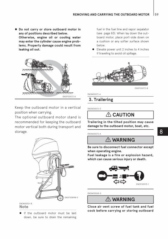
REMOVING AND CARRYING THE OUTBOARD MOTOR 59
8
Do not carry or store outboard motor in
any of positions described below.
Otherwise, engine oil or cooling water
may enter the cylinder cause engine prob-
lems. Property damage could result from
leaking oil out.
Keep the outboard motor in a vertical
position when carrying.
The optional outboard motor stand is
recommended for keeping the outboard
motor vertical both during transport and
storage.
ENON00021-B
Note
If the outboard motor must be laid
down, be sure to drain the remaining
fuel in the fuel line and vapor sepalator
(see page 83). When lay down the out-
board motor, place port-side down on
a cushion or any softer surface shown
below.
Elevate power unit 2 inches to 4 inches
if traveling to avoid oil spillage.
ENOM00072-A
ENOW00072-0
Trailering in the tilted position may cause
damage to the outboard motor, boat, etc.
ENOW00073-A
Be sure to disconnect fuel connector except
when operating engine.
Fuel leakage is a fire or explosion hazard,
which can cause serious injury or death.
ENOW00068-0
Close air vent screw of fuel tank and fuel
cock before carrying or storing outboard
ENOF00072-A
ENOF0089B-0
3. Trailering
CAUTION
WARNING
WARNING
ENOF00072-B
ENOF00075-1

REMOVING AND CARRYING THE OUTBOARD MOTOR60
8
motor and fuel tank, or fuel may leak, poten-
tially catching fire.
ENOW00071-0
The tilt support device supplied on your out-
board motor is not intended for towing. It is
intended to support the outboard motor
while the boat is docked, beached, etc.
When transporting a boat on a trailer
with the outboard motor still attached,
disconnect the fuel line from the out-
board motor beforehand and keep the
outboard motor in the normal running
position or on a transom saver bar.
Tiller handle typeTo prevent the outboard motor from
moving when it is attached on a boat
during transport on a trailer, properly
tighten the steering fric tion lever
(page 61).
1. Ground clearance should be provided sufficiently.
2. Transom saver bar
ENOW00067-0
Do not go under outboard motor tilted up
even if it is supported by support bar, or
accidental fall of outboard motor could lead
to severe personal injury.
CAUTION
WARNING
2 1
ENOF00074-A

61
9
ADJUSTMENT
ENOM00073-0
Tiller handle typeENOW00074-A
Do not overtighten the steering friction lever
it could result in difficulty of movement
resulting in the loss of control causing an
accident and could lead to severe injury.
Adjust this lever to achieve the desired
steering friction (drag) on the tiller han-
dle. Move lever towards (2) to decrease
friction and move lever towards (3) to
increase friction.
1. Steering friction lever2. Decrease3. Increase
ENOM00074-A
ENOW00074-B
Do not overtighten the throttle adjustment
screw or it could result in difficulty of move-
ment resulting in the loss of control causing
an accident and could lead to severe injury.
Friction adjustment of the throttle grip
can be made with the throttle adjust-
ment screw.
1. Throttle friction adjustment screw2. Decrease3. Increase
ENOM00075-1
ENOW00074-C
Do not overtighten the remote control
throttle friction adjustment screw or it
could result in diff iculty of movement
resulting in the loss of control causing an
accident and could lead to severe injury.
To adjust the friction of the remote con-
trol lever, turn the throttle friction
adjustment screw on the front of the
remote control . Turn clockwise to
increase the friction and counter-clock-
wise to decrease it.
1. Steering friction
WARNING
2. Throttle grip friction
WARNING
1
23
ENOF00910-0
3. Remote control lever friction
WARNING
1
3
2
ENOF00911-1

ADJUSTMENT62
9
Side mount type
1. Throttle friction adjustment screw2. Decrease3. Increase
Top mount type
1. Throttle friction adjustment screw2. Lighter3. Heavier
ENOM00076-0
ENOW00076-1
Be sure that outboard motor is secured to
transom or service stand, or accidental
drop or fall of outboard motor could lead
to severe personal injury.
Be sure to lock outboard motor when it is
tilted up, otherwise accidental fall of out-
board motor could lead to severe per-
sonal injury.
Do not go under outboard motor tilted up
and locked, or accidental fall of outboard
motor could lead to severe personal
injury.
ENOW00075-1
Inappropriate adjustment of trim tab could
cause steering difficulty. After installing or
readjusting trim tab, check if steering load is
even.
If straight-line cruising can not be
achieved, adjust the trim tab located
under the anti-ventilation plate.
If the boat veers toward the left direct
the trim tab towards A (left from rear
of boat).
If the boat veers toward the right
direct the trim tab towards B (right
from rear of boat).
1. Trim tab
ENON00022-A
Notes
After adjustment securely tighten the
trim tab fixing bolt.
Check for looseness of the bolt and
the trim tab at regular intervals.
4. Trim tab adjustment
WARNING
1
23
ENOF00078-2
12
3ENOF00942-0
WARNING
11ENOF00912-A

63
10
INSPECTION AND MAINTENANCE
ENOM00077-0
Care of your outboard motorTo keep your outboard motor in the best
operating condition, it is very important
that you perform daily and periodic
maintenance as suggested in the main-
tenance schedules that follow.
ENOW00077-0
Your personal safety and that of your pas-
sengers depends on how well you main-
tain your outboard motor. Carefully
observe all of the inspection and mainte-
nance procedures described in this sec-
tion.
The maintenance intervals shown in the
checklist apply to an outboard motor in
normal use. If you use your outboard
motor under severe conditions such as
frequent full-throttle operation, fre-
quent operation in brackish water, or for
commercial use, maintenance should be
performed at shor ter inter vals. If in
doubt, consult your dealer for advice.
We strongly recommend that you use only
genuine replacement parts on your out-
board motor. Damage to your outboard
motor arising from the use of other than
genuine parts is not covered under the
warranty.
CAUTION

INSPECTION AND MAINTENANCE64
10
ENOM00079-0
Perform the following checks before and
after use.
ENOW00078-1
Do not use outboard motor if any abnormal-
ity is found during pre-operation check oth-
erwise it could result in severe damage to
the motor or severe personal injury.
1. Daily Inspection
WARNING
Item Points to Check Remedy
Fuel System
• Check the amount of fuel in the tank. Replenish
• Check for debris or water in the fuel filters. Clean or replace if
necessary
• Check the rubber hoses for fuel leakage. Replace if necessary
Fuel Tank Cap
• Check for crack, leakage, damage in the fuel tank cap. Replace if necessary
• Check for crack, damage in the gasket. Replace if necessary
• Check for leakage at full close. Replace if necessary
Engine Oil • Check the oil level. Fill oil
Electrical Equipment
• Check that the main switch functions normally. Replace if necessary
• Check that the battery electrolyte level and specific gravity
are normal.
Replenish or recharge
• Check for loose connections on the battery terminal. Retighten
• Check that the stop switch functions normally and make sure
the stop switch lock is there.
Remedy or replace if
necessary
• Check cords for loose connections and damage. Correct or replace if
necessary
• Check the spark plugs for dirt, wear and carbon build-up. Clean or replace if
necessary
• Check the warning buzzer (one beep) and warning LED lamp
(ON for 1 secs.) when key is ON.
Repair
Clutch and Propeller Sys-
tem
• Check that clutch engages correctly when operating the shift
lever.
Adjust
• Visually Check propeller for bent or damaged blades. Replace if necessary
• Check the propeller nut is tightened and the split pin is
present.
Tighten or replace
Installation of Motor
• Check all the bolts attaching the motor to the boat. Tighten
• Check the thrust rod installation. Replace if necessary
Power Trim & Tilt
• Check working of the tilt up and down of the motor. Repair
Cooling Water• Check that cooling water is discharged from the cooling
water check port after the engine has started.
Repair
Tools and Spares
• Check that there are tools and spare parts for replacing
spark plugs, the propeller, etc.
• Check that you have the spare rope and stop switch lock.
Order
Order
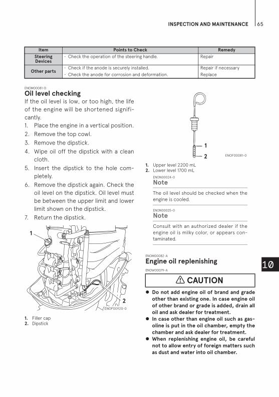
INSPECTION AND MAINTENANCE 65
10
ENOM00081-D
Oil level checkingIf the oil level is low, or too high, the life
of the engine will be shortened signifi-
cantly.
1. Place the engine in a vertical position.
2. Remove the top cowl.
3. Remove the dipstick.
4. Wipe oil off the dipstick with a clean
cloth.
5. Insert the dipstick to the hole com-
pletely.
6. Remove the dipstick again. Check the
oil level on the dipstick. Oil level must
be between the upper limit and lower
limit shown on the dipstick.
7. Return the dipstick.
1. Filler cap2. Dipstick
1. Upper level 2200 mL2. Lower level 1700 mL
ENON00024-0
Note
The oil level should be checked when the
engine is cooled.
ENON00025-0
Note
Consult with an authorized dealer if the
engine oil is milky color, or appears con-
taminated.
ENOM00082-A
Engine oil replenishingENOW00079-A
Do not add engine oil of brand and grade
other than existing one. In case engine oil
of other brand or grade is added, drain all
oil and ask dealer for treatment.
In case other than engine oil such as gas-
oline is put in the oil chamber, empty the
chamber and ask dealer for treatment.
When replenishing engine oil, be careful
not to allow entry of foreign matters such
as dust and water into oil chamber.
Steering Devices
• Check the operation of the steering handle. Repair
Other parts• Check if the anode is securely installed. Repair if necessary
• Check the anode for corrosion and deformation. Replace
Item Points to Check Remedy
1
2ENOF00920-0
CAUTION
2
1
ENOF00081-0

INSPECTION AND MAINTENANCE66
10
Wipe off engine oil well immediately if
spilled and dispose of it in accordance
with local fire prevention and environ-
ment protection regulations.
Do not replenish engine oil over upper
limit. If overfilled, remove oil to upper
limit. If engine oil is over the upper limit,
it can leak potentially leading to engine
damage.
If the oil level is low, or at lowest mark,
add recommended oil to the middle
dipstick mark.
ENOM00083-1
Washing outboard motorENOW00920-0
When washing the outboard motor, be care-
ful not to spray the water inside of the top
cowl, especially electrical components.
ENON00026-0
Note
It is recommended to check chemical
properties of water on which your out-
board motor is regularly used.
If outboard motor is used in salt water,
brackish water or water with a high
acidic level, use fresh water to remove
salt, chemicals or mud. And flush cooling
water passage after every cruising or
before storing outboard motor for long
time. Before flushing, remove the pro-
peller and the forward thrust holder.
ENOM00085-E
Flushing hose jointENOW00921-0
Do not operate the engine when flushing the
outboard motor with a hose joint as this can
cause damage to the outboard motor.
ENOW00922-0
To prevent the engine from starting when
you are near the propeller, remove the stop
switch lock.
1. Tilt down the outboard motor.
2. Remove the flushing connector cap
from the outboard motor, and screw
in the hose joint.
3. Connect a water hose. Turn on the
water and adjust the flow.
Continue flushing the outboard motor
for 3 to 5 minutes
4. After the flushing, be sure to reattach
the flushing connector cap.
5. Tilt up the outboard motor.
CAUTION
ENOF00850-0
CAUTION
CAUTION

INSPECTION AND MAINTENANCE 67
10
.
1. Hose joint
ENOM00085-A
Flushing by test tankENOW00081-0
Do not start engine without removing pro-
peller, or accidentally turning propeller
could cause personal injury.
ENOW00082-0
Never start or operate the engine indoors or
in any space which is not well ventilated.
Exhaust gas contains carbon monoxide, a
colorless and odorless gas which can be fatal
if inhaled for any length of time.
ENOW00036-A
When the engine is started in the test tank,
to avoid over heating and water pump dam-
age, be sure the water level is at least 10 cm
(4 in.) above the anti ventilation plate.
And be sure to remove the propeller, when
starting the engine in the test tank. (See
page 75)
Run the engine only at idling.
1. Test tank2. Water3. Over 10 cm (4 in.)
ENOM00950-0
Fuse replacementENOW00923-0
Before replacing a fuse, disconnect the bat-
tery cable from the battery negative (-) ter-
minal. Failure to do so may cause a short-
circuit.
ENOW00924-0
Never use a fuse with a rating that exceeds
the specified rating as this could cause seri-
ous damage to the electrical system.
If a blown fuse is detected, try to deter-
mine the cause for this and correct it. If
the cause for the problem is not cor-
rected, the fuse will likely blow again.
If the fuse continues to blow, request an
authorized Tohatsu dealer to inspect the
outboard motor.
1. Stop the engine and disconnect the
battery cable from the battery nega-
tive (-) terminal.
WARNING
WARNING
CAUTION
1
ENOF00921-0
CAUTION
CAUTION
1
3
2
ENOF00863-0

INSPECTION AND MAINTENANCE68
10
2. Remove the engine cover.
3. Remove the fuse box lid.
4. Remove the fuse and check it. If the
fuse is blown, replace it with a fuse
of the same specified rating. The
outboard motor is supplied with
spare fuses in the spare fuse holder.
1. Blown fuse
4
1 2 3
1 2 3
ENOF00922-1
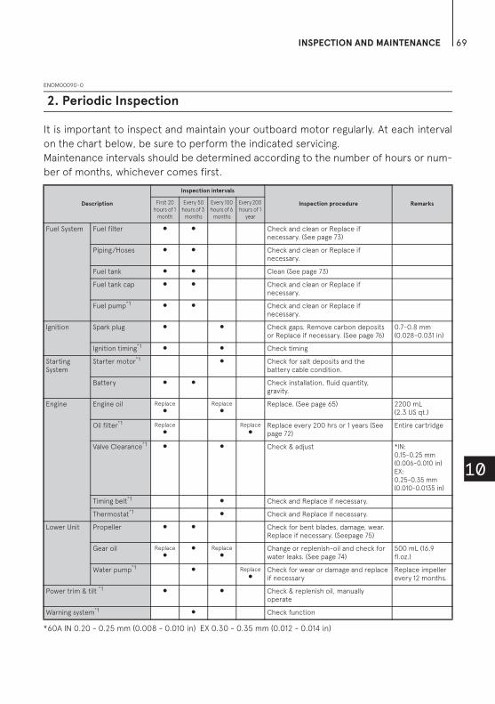
INSPECTION AND MAINTENANCE 69
10
ENOM00090-0
It is important to inspect and maintain your outboard motor regularly. At each interval
on the chart below, be sure to perform the indicated servicing.
Maintenance intervals should be determined according to the number of hours or num-
ber of months, whichever comes first.
2. Periodic Inspection
Description
Inspection intervals
Inspection procedure RemarksFirst 20
hours of 1
month
Every 50
hours of 3
months
Every 100
hours of 6
months
Every 200
hours of 1
year
Fuel System Fuel filter Check and clean or Replace if necessary. (See page 73)
Piping/Hoses Check and clean or Replace if necessary.
Fuel tank Clean (See page 73)
Fuel tank cap Check and clean or Replace if necessary.
Fuel pump*1 Check and clean or Replace if necessary.
Ignition Spark plug Check gaps. Remove carbon deposits or Replace if necessary. (See page 76)
0.7-0.8 mm (0.028-0.031 in)
Ignition timing*1 Check timing
Starting System
Starter motor*1 Check for salt deposits and the battery cable condition.
Battery Check installation, fluid quantity, gravity.
Engine Engine oil Replace Replace Replace. (See page 65) 2200 mL(2.3 US qt.)
Oil filter*1 Replace Replace Replace every 200 hrs or 1 years (See page 72)
Entire cartridge
Valve Clearance*1 Check & adjust *IN: 0.15-0.25 mm (0.006-0.010 in) EX: 0.25-0.35 mm (0.010-0.0135 in)
Timing belt*1 Check and Replace if necessary.
Thermostat*1 Check and Replace if necessary.
Lower Unit Propeller Check for bent blades, damage, wear. Replace if necessary. (Seepage 75)
Gear oil Replace Replace Change or replenish-oil and check for water leaks. (See page 74)
500 mL (16.9 fl.oz.)
Water pump*1 Replace Check for wear or damage and replace if necessary
Replace impeller every 12 months.
Power trim & tilt *1 Check & replenish oil, manually operate
Warning system*1 Check function
*60A IN 0.20 - 0.25 mm (0.008 - 0.010 in) EX 0.30 - 0.35 mm (0.012 - 0.014 in)

INSPECTION AND MAINTENANCE70
10
*1: Have this handled by your dealer.
ENON00030-0
Note
Your outboard motor should receive careful, and complete inspection at 300 hours. This is the
best time for major maintenance procedures to be carried out.
ENOM00091-A
Engine oil replacementENOW00091-0
You may be injured due to high engine tem-
peratures if you fill engine oil just after stop-
ping. Changing engine oil should be done
after the engine has been cooled.
ENOW00092-A
Do not overfill engine oil, or engine oil
could leak and/or engine could be dam-
aged. If engine oil level is over upper limit
marks of oil gauge, drain oil to level lower
than upper limit.
Be sure that outboard motor is in upright
and level position when checking or
changing oil.
Stop engine immediately if low oil pres-
sure warning lamp is lit or oil leak is found,
or engine could be severely damaged.
Consult dealer.
Wipe off engine oil well immediately if
spilled and dispose of it in accordance
with local fire prevention and environ-
ment protection regulations.
ENOW00090-0
Use of engine oils that do not meet these
requirements will result in reduced engine
life, and other engine problems.
ENOW00933-0
Engine oil mixed with dust or water will dra-
matically shorten the life of the engine.
To change engine oil:
Be sure to use recommended engine oil.
1. Stop the engine and allow it to cool.
2. Tilt up the outboard motor and lock
the tilt with the tilt stopper.
3. Turn the steering on the outboard
motor so that the drain hole is facing
downward.
4. Put a oil drain pan under the oil drain
screw.
5. Remove the oil drain screw and com-
pletely drain oil from the engine.
Bolts and Nuts Retighten
Sliding and Rotating Parts. Grease Nipples
Apply and pump in grease. (See page 80)
Outer Equipment Check for corrosion.
Anode Check for corrosion and deformation. Replace if necessary.
Description
Inspection intervals
Inspection procedure RemarksFirst 20
hours of 1
month
Every 50
hours of 3
months
Every 100
hours of 6
months
Every 200
hours of 1
year
CAUTION
CAUTION
CAUTION
CAUTION

INSPECTION AND MAINTENANCE 71
10
1. Drain hole
6. Tighten the oil drain screw with apply-
ing oil on the sealing surface of screw.
(Use new oil drain washer)
Oil drain screw specified torque
24N·m (17 ft·lb, 2.4 kgf·m)
ENON00028-A
Note
If a torque-wrench is not available when
you are fitting a oil filter, a good estimate
of the correct torque is 3/4 to 1 a turn past
finger-tight. Have the oil filter adjusted to
the correct torque as soon as possible with
a torque-wrench.
7. Reset the engine in a vertical posi-
tion.
8. Repeat 2 to 7 procedures two or
three times to drain the oil com-
pletely.
9. Remove the top cowl and the oil filler
cap.
10. Fill the engine through filler port with
recommended oil to the middle of
dipstick mark.
11. Tighten the oil filler cap.
1. Filler cap2. Dipstick3. Filler port
1. Upper limit (Max.)2. Lower limit (Min.)
ENON00920-0
Note
Use only recommended engine oil (See
page 30)
1
ENOF00923-0
Oil volume needed for complete oil replacement
With oil filterreplacement
Without oil filterreplacement
Approximately 2400 mL
(2.5 US qt.)
Approximately 2200 mL
(2.3 US qt.)
1
2
3
ENOF00924-0
2
1
ENOF00113-0

INSPECTION AND MAINTENANCE72
10
ENOW00925-0
Wipe off engine oil well immediately if
spilled and dispose of it in accordance with
local fire prevention and environment pro-
tection regulations.
ENON00031-0
Note
If any amount of water is found in engine
oil, making it milky white, consult dealer.
If engine oil is contaminated with fuel,
emitting strong fuel smell, consult dealer.
Some oil dilution is normal if engine is
idled or trolled for long periods, especially
in cooler water temperatures.
ENOM00092-A
Oil filter replacementENOW00091-0
You may be injured due to high engine tem-
peratures if you fill engine oil just after stop-
ping. Changing engine oil should be done
after the engine has been cooled.
ENOW00926-0
Wipe off engine oil well immediately if
spilled and dispose of it in accordance with
local fire prevention and environment pro-
tection regulations.
1. Drain oil from the engine.
2. Place a rag or towel below the oil fil-
ter to absorb any spilled oil.
3. Unscrew old filter by turning the fil-
ter to counter clockwise.
4. Clean the mounting base. Apply film
of clean oil to O-ring.
Do not use grease.
Install oil filter and tighten it to specified
torque by using oil filter wrench.
Oil filter torque:
18 N·m (13 ft·lb, 1.8 kgf·m)
ENON00028-A
Note
If a torque-wrench is not available when
you are fitting a oil filter, a good estimate
of the correct torque is 3/4 to 1 a turn
past finger-tight. Have the oil filter
adjusted to the correct torque as soon as
possible with a torque-wrench.
1. Oil filter wrenchP/N 3AC-99090-0P/N 3AC99090M(US. CANADA Only)
1. Oil filter2. Fuel filter
CAUTION
CAUTION
CAUTION
1ENOF00094-0
12 ENOF00925-0

INSPECTION AND MAINTENANCE 73
10
ENOM00093-A
Fuel filters and fuel tank cleaningENOW00093-A
Gasoline and its vapors are very flammable
and can be explosive.
Do not start this procedure while engine
is operating or hot even after stopping it.
Place fuel filter away from every source of
ignition such as sparks or open flames.
Wipe off gasoline well immediately if
spilled and dispose of it in accordance
with local fire prevention and environ-
ment protection regulations.
Install fuel filter with all related parts in
place, or fuel leak could occur, leading to
catching fire or explosion.
Check fuel system regularly for leakage.
Contact authorized dealer for fuel system
services. Services by unqualified person
could lead to engine damage.
Fuel filters are provided inside the fuel
tank and engine.
ENOM00094-0
Fuel filter (for engine)1. Check in the cup for water and
debris.
1. Body2. O-ring3. Filter4. O-ring
5. Float6. Cup7. Indication of Fuel Flow.
2. If present, disconnect hoses from
the fuel connector (male) and the
fuel pump.
3. Remove the cup, filter and O-rings
from the fuel filter body.
4. Check the wear and clogging for
each parts, and replace if necessary.
5. Remove fuel and any water or debris
from the cup, filter and hoses.
6. Reassemble all parts.
ENOM00096-A
Fuel filter (for fuel tank)Water or dirt in the fuel tank will cause
engine performance problems.
Check and clean the tank at specified
times or after the outboard motor has
been stored for a long period of time
(over three months).
1. Remove four screws to remove the
Fuel Pick-Up.
2. Clean the fuel filter and replace the
gasket.
3. Reassemble all parts.
WARNING
1
27
3
4
6
5
ENOF00096-A
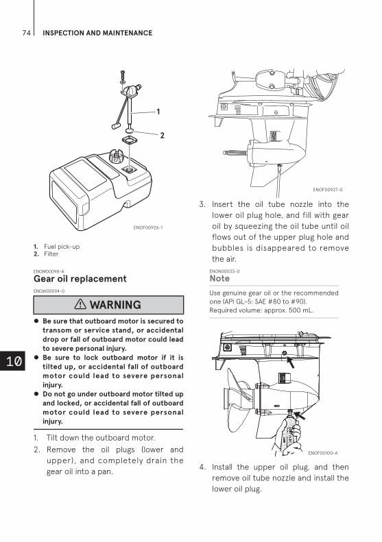
INSPECTION AND MAINTENANCE74
10
1. Fuel pick-up2. Filter
ENOM00098-A
Gear oil replacementENOW00094-0
Be sure that outboard motor is secured to
transom or service stand, or accidental
drop or fall of outboard motor could lead
to severe personal injury.
Be sure to lock outboard motor if it is
tilted up, or accidental fall of outboard
motor could lead to severe personal
injury.
Do not go under outboard motor tilted up
and locked, or accidental fall of outboard
motor could lead to severe personal
injury.
1. Tilt down the outboard motor.
2. Remove the oil plugs (lower and
upper), and completely drain the
gear oil into a pan.
3. Insert the oil tube nozzle into the
lower oil plug hole, and fill with gear
oil by squeezing the oil tube until oil
flows out of the upper plug hole and
bubbles is disappeared to remove
the air.
ENON00033-0
Note
Use genuine gear oil or the recommended
one (API GL-5: SAE #80 to #90).
Required volume: approx. 500 mL.
4. Install the upper oil plug, and then
remove oil tube nozzle and install the
lower oil plug.
WARNING
2
1
ENOF00926-1
ENOF00927-0
ENOF00100-A

INSPECTION AND MAINTENANCE 75
10
Oil plug specified tightening torque
4N·m (3 ft·lb, 0.4 kgf·m)
ENOW00095-0
Do not reuse oil plug gasket. Always use new
gasket and tighten oil plug properly to pre-
vent entry of water into lower unit.
ENOW00928-0
Wipe off gear oil well immediately if spilled
and dispose of it in accordance with local
fire prevention and environment protection
regulations.
ENON00032-0
Note
If water in the oil, giving it a milky colored
appearance. Contact your dealer.
ENOM00086-A
Propeller replacementENOW00084-0
Do not begin propeller removal and
installation procedure with spark plug
caps at tache d, shi f t in for ward or
reverse, main switch at other than “OFF”,
engine stop switch lock attached to the
switch, and starter key attached, or
engine could accidentally start leading to
serious personal injury. Disconnect bat-
tery cable if possible.
The propeller edge is thin and sharp.
Wear the groves during replacement to
protect your hands.
ENOW00086-0
Do not install propeller without thrust
holder, or propeller boss could be dam-
aged.
Do not reuse split pin.
After installing split pin, spread the pin
apart to prevent it from falling out which
could lead to the propeller coming off
during operation.
A worn-out or bent propeller will lower
the motor's performance, and cause
engine trouble.
1. Put a piece of wood block between
propeller blade and anti-ventilation
plate to hold propeller.
CAUTION
CAUTION
ENOF00101-A
WARNING
CAUTION

INSPECTION AND MAINTENANCE76
10
2. Remove the split pin, propeller nut
and washer.
3. Remove the propeller and thrust
holder.
4. Apply water proof grease to the pro-
peller shaft before installing a new
propeller.
5. Install the thrust holder, propeller,
stopper, washer and propeller nut
onto the shaft.
1. Propeller2. Thrust holder3. Stopper4. Washer5. Nut6. Split pin
6. Tighten the propeller nut to speci-
fied torque, and align one of grooves
to propeller shaft hole.
Propeller nut torque:
35 N·m (25 ft·lb, 3.5kgf·m)
7. Install a new split pin into the nut
hole and bend it.
ENOM00087-C
Spark plugs replacementENOW00087-0
Do not reuse spark plug with damaged
insulation, or sparks can leak through
crack, potentially leading to electric
shock, explosion and/or fire.
Do not touch spark plugs immediately
after stopping engine as they will be hot
and could cause severe burns if touched.
Allow motor to cool down first.
ENOW00929-A
Use only the recommended spark plugs.
Spark plugs which have an different heat
range may cause engine damage.
Do not clean electrodes of iridium spark
plug. If it is contaminated with carbon
deposit or dirt, replace with a new one.
Do not adjust the plug gasp, if it is out of
specification, replace with a new one.
If the spark plug(s) is fouled, has carbon
build up, or is worn, it should be
replaced.
1. Stop the engine.
2. Remove the top cowl.
ENOF00084-B
12
34
6
5
ENOF00084-A
WARNING
CAUTION
ENOF00084-E
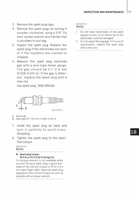
INSPECTION AND MAINTENANCE 77
10
3. Remove the spark plug caps.
4. Remove the spark plugs by turning it
counter-clockwise, using a 5/8" (16
mm) socket wrench and handle that
is provided in tool bag.
5. Inspect the spark plug. Replace the
spark plug if the electrodes are worn
or if the insulators are cracked or
chipped.
6. Measure the spark plug electrode
gap with a wire type feeler gauge.
The gap should be 0.7-0.8 mm
(0.028-0.031 in). If the gap is differ-
ent, replace the spark plug with a
new one
Use spark plug ; NGK IKR6G8
1. Electrode2. Spark gap (0.7–0.8 mm, 0.028–0.031 in)
7. Install the spark plug by hand and
turn it carefully to avoid cross-
threading.
8. Tighten the spark plug to the speci-
fied torque.
ENON00028-0
Note
Spark plug torque:
18.0 N·m (13.3 ft·lb) [1.84 kgf·m]
If a torque-wrench is not available when
you are fitting a spark plug, a good esti-
mate of the correct torque is 1/4 to 1/2 a
turn past finger-tight. Have the spark plug
adjusted to the correct torque as soon as
possible with a torque-wrench.
ENON00938-0
Note
1. Do not clean electrodes of the spark
plug by a brush, or an iridium tip on the
electrodes could be damaged.
2. Do not adjust the plug gap, if it is out of
specification, replace the spark plug
with a new one.
12
ENOF00085-0

INSPECTION AND MAINTENANCE78
10
ENOM00088-A
Anode replacementA sacrificial anode protects the outboard motor from electrolytic corrosion. Anode is
located on the gear case, cylinder etc.. When the anode is eroded more than 1/3 of
original size, replace it.
ENON00029-0
Notes
Never grease or paint the anode.
At each inspection re-tighten the anode attaching bolt. As it is likely to be subjected to electrolytic
corrosion.
*1 : Both side
*1 *1
ENOF00928-1
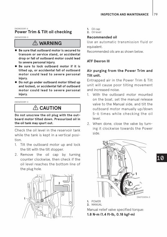
INSPECTION AND MAINTENANCE 79
10
ENOM00089-A
Power Trim & Tilt oil checkingENOW00088-0
Be sure that outboard motor is secured to
transom or service stand, or accidental
drop or fall of outboard motor could lead
to severe personal injury.
Be sure to lock outboard motor if it is
tilted up, or accidental fall of outboard
motor could lead to severe personal
injury.
Do not go under outboard motor tilted up
and locked, or accidental fall of outboard
motor could lead to severe personal
injury.
ENOW00089-0
Do not unscrew the oil plug with the out-
board motor tilted down. Pressurized oil in
the oil tank may spurt out.
Check the oil level in the reservoir tank
while the tank is kept in a vertical posi-
tion.
1. Tilt the outboard motor up and lock
the tilt with the tilt stopper.
2. Remove the oil cap by turning
counter clockwise, then check if the
oil level reaches the bottom line of
the plug hole.
1. Oil cap2. Oil level
Recommended oil
Use an automatic transmission fluid or
equivalent.
Recommended oils are as shown below.
ATF Dexron III
Air purging from the Power Trim and
Tilt unit.
Entrapped air in the Power Trim & Tilt
unit will cause poor tilting movement
and increased noise.
1. With the outboard motor mounted
on the boat, set the manual release
valve to the Manual side, and tilt the
outboard motor manually up/down
5-6 times while checking the oil
level.
2. When done, close the valve by turn-
ing it clockwise towards the Power
side.
1. POWER2. MANUAL
Manual relief valve specified torque:
1.8 N-m (1.4 ft-lb, 0.18 kgf-m)
WARNING
CAUTION
1
2
ENOF00929-0
2
1
ENOF0089A-0

INSPECTION AND MAINTENANCE80
10
ENOM00960-0
Grease pointApply water proof grease to the parts shown below.
ENOF00931-0
INSPECTION AND MAINTENANCE 81
10
ENOM00100-A
ENOW00934-0
Be sure to disconnect fuel connector
except when operating engine.
Fuel leakage is a fire or explosion hazard,
which can cause serious injury or death.
ENOW00097-0
Be sure to use cloth to remove fuel remain-
ing in the cowl and dispose of it in accor-
dance with local f ire prevent ion and
environment protection regulations.
ENOW00096-0
Before servicing the motor for storage:
Remove the battery cables.
Remove the spark plug caps from the
spark plugs.
Do not run the motor out of the water.
Before you put your outboard motor in
storage, it is a good opportunity to have
it serviced and prepared by your dealer.
Be sure to use fuel stabilizer while run-
ning the motor before storage. (See
page 82)
ENOM00101-A
Engine1. Wash the engine exterior and flush
the cooling water system thoroughly
with fresh water. Drain the water
completely.
Wipe off any surface water with an
oily rag.
2. Use a dry cloth to completely wipe
off water and salt from the electrical
components.
3. Drain all fuel from the fuel hoses,
fuel pump, fuel filter (See page 73)
and vapor separator (See page 83),
and clean these parts.
Keep in mind that if gasoline is kept
in the vapor separator for a long
time, gum and varnish will develop,
causing the float valve to stick,
restricting the fuel flow.
4. Remove the spark plugs and put a
teaspoon of engine oil or spray stor-
age oil into the combustion chamber
through the spark plug holes.
5. Turn the starter motor several turns
to lubricate inside the cylinder.
ENOW00930-0
Be sure to remove stop switch lock to
prevent ignited the spark plugs.
Put a cloth to spark plug hole and wipe up
any spilled engine oil, when cranking the
outboard motor.
6. Change the engine oil (See page 70).
7. Change the gear oil in the gear case
(See page 74).
8. Apply grease to grease point (See
page 80).
3. Off-season storage
WARNING
WARNING
CAUTION
WARNING

INSPECTION AND MAINTENANCE82
10
9. Stand the outboard motor up verti-
cally in a dry place.
ENOW00066-D
Do not carry or store outboard motor in any
of positions described below.
Otherwise, engine oil or cooling water may
enter the cylinder cause engine problems.
Property damage could result from leaking
oil out.
ENON00021-B
Note
If the outboard motor must be laid
down, be sure to drain the remaining
fuel in the fuel line and vapor sepalator
(see page 83). When lay down the out-
board motor, place port-side down on
a cushion or any softer surface shown
below.
Elevate power unit 2 inches to 4 inches
if traveling to avoid oil spillage.
ENOM00950-0
Adding a fuel stabilizerWhen adding a fuel stabilizer additive
(commercially available), first fill the fuel
tank with fresh fuel. If the fuel tank is
only partially filled, air in the tank can
cause the fuel to deteriorate during
storage.
1. Before adding fuel stabilizer additive,
drain the vapor separator (See
page 83).
2. Follow the instructions on the label
when adding the fuel stabilizer addi-
tive.
3. After adding the additive, let the
outboard motor run in the water for
10 minutes to make sure any old fuel
in the fuel system has been com-
pletely replaced by the fuel with
additive.
4. Turn the engine OFF
ENON00891-0
Note
If your motor is used occasionally, it is
recommended to use a good fuel stabi-
lizer in every tank of fuel and keep the
container full to reduce condensation
and evaporation.
CAUTION
ENOF0089B-0
ENOF00072-A
ENOF00072-B

INSPECTION AND MAINTENANCE 83
10
ENOM00970-0
Fuel system drainingENOW00028-A
For details on handling fuel, contact an
authorized dealer.
Fuel and fuel vapors are extremely flamma-
ble and can be explosive.
If fuel is spilled, wipe it up immediately.
Keep the fuel tank well away from sources
of ignition, e.g. sparks or open flames
Perform all work outdoors or in a well
ventilated place.
ENOW00097-0
Be sure to use cloth to remove fuel remain-
ing in the cowl and dispose of it in accor-
dance with local f ire prevent ion and
environment protection regulations.
1. Disconnect the fuel hose from the
outboard motor.
2. Remove the top cowl.
3. Release the drain tube from the
clamp and pull the tube outside the
bottom cowl. Place an approved fuel
container under the drain tube end
and use a funnel to avoid spilling
fuel.
4. Loosen the vapor separator drain
screw.
5. Tilt up the outboard motor until fuel
flows out of the drain tube.
6. Leave the outboard motor in this
position until all fue l has been
drained.
7. When thoroughly drained, retighten
the drain screw securely.
8. Check the drained fuel for the pres-
ence of water or other contami-
nants. I f e ither is present ,
reassemble the outboard motor,
refill the vapor separator with fuel,
and then drain the fuel again. Repeat
this procedure until no water or
other contaminants are present in
the drained fuel.
1. Vapor separator
ENOM00102-0
BatteryENOW00931-A
Place the battery away from any source of
fire, sparks and open flames such as
burners or welding equipment.
Place the battery away from fuel tank.
Accidental sparks of battery may cause
explosion of gasoline.
1. Disconnect the battery cables and be
sure to remove the negative terminal
first.
2. Wipe off any chemical deposits, dirt,
or grease.
3. Apply grease to the battery termi-
nals.
WARNING
WARNING
WARNING
1
ENOF00932-0

INSPECTION AND MAINTENANCE84
10
4. Charge the battery completely before
storing it for the winter.
5. Recharge the battery once a month
to prevent it from discharging and the
electrolyte from deteriorating.
6. Store the battery in a dry place.
ENOM00104-A
The following steps must be taken when
first using the engine after off-season
storage.
1. Check that the shift and throttle
function properly. (Be sure to turn the
propeller shaft when checking the
shift function or else the shift linkage
may be damaged.)
2. Check the electrolyte level, and mea-
sure the voltage and specific gravity
of the battery.
3. Check that the battery is secure and
the batter y cables are properly
installed.
4. Change the engine oil (See page 70).
5. Before starting the engine, discon-
nect stop switch lock and crank
approximately 3times of 3sec. turn-
ing the starter motor in order to
prime the oil pump.
6. Fill fuel tank completely.
7. Start the engine and warm up the
engine for 3 minutes in the “NEU-
TRAL” position.
8. Run the engine for 5 minutes at the
slowest speed.
9. Run the engine for 10 minutes at half
throttle. The oil used for storage
inside the engine will be circulated
out to assure optimum performance.
ENOM00105-A
ENOW00098-0
Do not attempt to start submerged outboard
motor immediately after it is recovered, or
engine could be severely damaged.
After taking your outboard motor out of
the water, immediately take it to your
dealer.
The following are the emergency mea-
sures to be taken for a submerged out-
board motor, if you can not take it your
dealer right away.
1. Wash the outboard motor with fresh
water to remove salt or dirt.
2. Remove the engine oil drain screw
and completely drain water and oil
from the engine.
3. Remove the spark plugs, and com-
pletely drain the water from the
engine by pulling emergency starter
rope (See page 42) several times.
Replace oil filter and oil to the correct
4. Pre-season check
Specific Grav-ity at 20°C
Terminal Voltage (V)
Charge Condition
1.120 10.5 Fully
discharged
1.160 11.1 1/4 charged
1.210 11.7 1/2 charged
1.250 12 3/4 charged
1.280 13.2 Fully charged
5. Submerged outboard motor
CAUTION
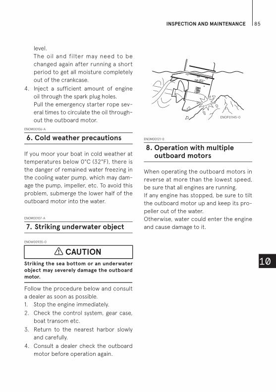
INSPECTION AND MAINTENANCE 85
10
level.
The oil and filter may need to be
changed again after running a short
period to get all moisture completely
out of the crankcase.
4. Inject a sufficient amount of engine
oil through the spark plug holes.
Pull the emergency starter rope sev-
eral times to circulate the oil through-
out the outboard motor.
ENOM00106-A
If you moor your boat in cold weather at
temperatures below 0°C (32°F), there is
the danger of remained water freezing in
the cooling water pump, which may dam-
age the pump, impeller, etc. To avoid this
problem, submerge the lower half of the
outboard motor into the water.
ENOM00107-A
ENOW00935-0
Striking the sea bottom or an underwater
object may severely damage the outboard
motor.
Follow the procedure below and consult
a dealer as soon as possible.
1. Stop the engine immediately.
2. Check the control system, gear case,
boat transom etc.
3. Return to the nearest harbor slowly
and carefully.
4. Consult a dealer check the outboard
motor before operation again.
ENOM00121-0
When operating the outboard motors in
reverse at more than the lowest speed,
be sure that all engines are running.
If any engine has stopped, be sure to tilt
the outboard motor up and keep its pro-
peller out of the water.
Otherwise, water could enter the engine
and cause damage to it.
6. Cold weather precautions
7. Striking underwater object
CAUTION
8. Operation with multiple outboard motors
ENOF01145-0

86
11
TROUBLESHOOTING
ENOM00108-0
If you encounter a problem, consult the check list below to determine the cause and to
take the proper action.
An authorized dealer will always be happy to provide any assistance and information.
Dif
fic
ult
to
sta
rt e
ng
ine
En
gin
e r
un
s e
rra
tic
all
y
Lo
w e
ng
ine
sp
ee
d/
Po
or
bo
at
spe
ed
Ba
tte
ry w
ill
no
t h
old
ch
arg
e
Sta
rte
r m
oto
r w
ill
no
t c
ran
k
Po
we
r T
& T
in
op
era
tive
Wa
rnin
g l
am
p A
“O
N”
Wa
rnin
g l
am
p B
“F
lash
”
Wa
rnin
g l
am
p C
“F
lash
”
Th
ree
wa
rnin
g l
am
ps
“F
lash
”
Wa
rnin
g b
uzz
er
“O
N”
Possible cause
FU
EL
SY
ST
EM
Empty fuel tank
Incorrect connection of fuel system
Air entering fuel line
Deformed or damaged fuel hose
Closed air vent on fuel tank
Clogged fuel filter or fuel pump
Fuel pump mulfunction
Use of improper engine oil
Use of improper gasoline
Not enough fuel supply by primer
EL
EC
TR
ICA
L S
YS
TE
M
Electrical components out of range or improper
or loose wiring connection.
Spark plug other than specified
Dirt, soot, etc. on spark plug
No Spark or weak spark
Short circuit of engine stop switch
Lack of stop switch lock plate
Rectifier failure
Blown 30 Amp fuse in the starting circuit
Not shifted into neutral position
Weak battery or battery connections are loose
or corroded
Ignition key switch failure
Starter motor or starter solenoid failure
Power trim & tilt switch defective, Solenoid is
defective

TROUBLESHOOTING 87
11
CO
MP
RE
SS
ION
&
OIL
SY
ST
EM
Low compression
Carbon deposits in the combustion chamber
Incorrect valve clearance
Low oil pressure/level, oil pump failure, Clogged
oil filter (Pressure switch ON)
Insufficient cooling water flow, clogged or
defective pump
OT
HE
RS
Faulty thermostat
Cavitations or ventilation
Incorrect propeller selection
Damaged or bent propeller
Improper thrust rod position
Unbalanced load on boat
Transom too high or too low
A great deal of air is contained inside pump
Insufficient throttle aperture
Dif
fic
ult
to
sta
rt e
ng
ine
En
gin
e r
un
s e
rra
tic
all
y
Lo
w e
ng
ine
sp
ee
d/
Po
or
bo
at
spe
ed
Ba
tte
ry w
ill
no
t h
old
ch
arg
e
Sta
rte
r m
oto
r w
ill
no
t c
ran
k
Po
we
r T
& T
in
op
era
tive
Wa
rnin
g l
am
p A
“O
N”
Wa
rnin
g l
am
p B
“F
lash
”
Wa
rnin
g l
am
p C
“F
lash
”
Th
ree
wa
rnin
g l
am
ps
“F
lash
”
Wa
rnin
g b
uzz
er
“O
N”
Possible cause

88
12
ACCESSORIES KIT
ENOM00109-1
The followings are a list of the tools and spare parts provided with the motor.
Items Quantity Remark
Service tools
Tool bag 1
Pliers 1
Socket wrench 1 10 × 13 mm
Socket wrench 1 16 mm (spark plug)
Socket wrench handle 1
Screwdrivers 1 Cross-and straight-point
Screwdriver handle 1
Spare parts
Emergency starter rope 1
Spark plug 1 NGK: IK6G8
Split pin 1
Stop switch lock 1
Parts Packaged
with Engine
Fuel tank 1 25 L
Primer bulb 1 set
Rigging bolt set
Bolt 2 M12P1.25 x 105 mm
Washer 4 13-34-3
Washer 4 M12
Nylon locking nut 4 M12P1.25
Remote Control Fitting
Assy1
Cable joint set
Cable joint 2
Washer 2 8.5-18-1.6
Snap pin 2
Hose joint 1 For Flushing
For international models

89
13
PROPELLER TABLE
ENOM00111-0
Use a genuine propeller.
A propeller must be selected so that the engine RPM measured at wide open throttle
while cruising is within the recommended range.
5000–6000 min-1 (rpm)
Propeller Mark
Propeller Size (Number of Blades x Pitch x Diameter)
In. mm
Light boats CS17 3 × 17 × 11 3 × 432 × 280
CS16 3 × 16 × 11 3 × 406 × 279
CS15 3 × 15 × 11 3 × 381 × 278
CS14 3 × 14 × 11 3 × 356 × 279
CS13 3 × 13 × 10.9 3 × 330 × 277
CS12 3 × 12 × 11.1 3 × 305 × 283
CS11 3 × 11 × 11.4 3 × 279 × 290
CS9 3 × 9 × 12.2 3 × 229 × 311
Heavy boats 7 4 × 7.1 × 11.4 4 × 180 × 290


O W N E R’ S M A N U A L
5-4, Azusawa 3-Chome, Itabashi-Ku
Tokyo 174-0051, Japan
Tel: +81-3-3966-3117 Fax: +81-3-3966-0090
www.tohatsu.com
MFS 40AMFS 50AMFS 60A