Embed Size (px)
Citation preview
SmartSight
Operating Manual
Document Asyril_SMARTSIGHT_Operating_Manual_EN
000.100.530
Version C Date 03.04.2018
SmartSight
Operating Manual © Copyright Asyril S.A.
Table of Contents Version: C
000.100.530 2/50
Table of Contents
TABLE OF CONTENTS ................................................................................................................................................ 2
1. INTRODUCTION ................................................................................................................................................ 4
1.1. GENERAL INFORMATION ............................................................................................................................ 4
1.2. SAFETY INSTRUCTIONS ............................................................................................................................. 5
1.2.1. General instructions ............................................................................................................................. 5
1.2.2. Specific instructions ............................................................................................................................. 6
1.3. WARRANTY INFORMATION ......................................................................................................................... 6
2. DESCRIPTION ................................................................................................................................................... 7
2.1. PRODUCT OVERVIEW ................................................................................................................................ 7
2.2. GENERAL CHARACTERISTICS .................................................................................................................... 9
2.2.1. Vision specifications ........................................................................................................................... 10
2.2.2. General specifications ....................................................................................................................... 12
2.2.3. Architecture ......................................................................................................................................... 14
2.3. ELECTRICAL INTERFACES ........................................................................................................................ 16
2.3.1. Diagrams of basic configurations ..................................................................................................... 16
2.3.2. Control unit .......................................................................................................................................... 21
2.3.3. EasyConnect Box ............................................................................................................................... 24
2.4. MECHANICAL INTERFACES ...................................................................................................................... 30
2.4.1. Control unit .......................................................................................................................................... 30
2.4.2. EasyConnect Box ............................................................................................................................... 30
2.4.3. Vision Kit .............................................................................................................................................. 32
2.4.4. Asycube ............................................................................................................................................... 34
2.5. ACCESSORIES AND OPTIONAL MODULES ................................................................................................. 35
2.5.1. Lighting ................................................................................................................................................ 35
2.5.2. Control camera ................................................................................................................................... 40
2.5.3. Switch for multi-asycube connection ............................................................................................... 41
2.5.4. Calibration plates ................................................................................................................................ 41
3. TRANSPORTATION, HANDLING AND INSTALLATION ........................................................................ 43
3.1. PRODUCT PACKAGING, TRANSPORTATION AND HANDLING ...................................................................... 43
3.2. UNPACKING INSTRUCTIONS ..................................................................................................................... 43
3.3. INSTALLATION AND STORAGE ENVIRONMENT ........................................................................................... 43
3.3.1. Installation environment .................................................................................................................... 43
3.3.2. Storage environment ......................................................................................................................... 44
4. MAINTENANCE AND REPAIR ..................................................................................................................... 45
4.1. SAFETY INSTRUCTIONS ........................................................................................................................... 45
4.1.1. General instructions ........................................................................................................................... 45
4.2. PERSONNEL RESPONSIBLE FOR MAINTENANCE OR REPAIR OPERATIONS ................................................ 45
4.3. MAINTENANCE......................................................................................................................................... 46
4.3.1. Maintenance schedule ....................................................................................................................... 46
SmartSight
Operating Manual © Copyright Asyril S.A.
Table of Contents Version: C
000.100.530 3/50
4.3.2. General maintenance ........................................................................................................................ 46
4.4. REPAIRS ................................................................................................................................................. 47
4.5. TECHNICAL SUPPORT ............................................................................................................................. 48
4.5.1. For a better service … ....................................................................................................................... 48
4.5.2. Contact................................................................................................................................................. 48
REVISION TABLE ....................................................................................................................................................... 49
SmartSight
Operating Manual © Copyright Asyril S.A.
Introduction Version: C
000.100.530 4/50
1. Introduction
1.1. General information
This document is the property of Asyril S.A.; it may not be reproduced, modified or communicated, in
whole or in part, without our prior written authorisation. Asyril S.A. reserves the right to modify any
information contained in this document for reasons related to product improvements without prior
notice. Before using the product, please read this entire document in order to ensure that the product is
used correctly. However, if you encounter difficulties when using the product, do not hesitate to contact
our customer service department.
In this manual, the safety information that must be respected is split into three types: "Danger",
"Important" and "Note". These messages are identified as follows:
DANGER!
Failure to respect this instruction may result in serious physical injury.
DANGER!
This instruction identifies an electrical hazard. Failure to respect this instruction may result in
electrocution or serious physical injury due to an electric shock.
IMPORTANT!
Failure to respect this instruction may result in serious damage to equipment.
NOTE:
The reader's attention is drawn to this point in order to ensure that the product is used correctly.
However, failure to respect this instruction does not pose a danger.
Reference …
For more information on a specific topic, the reader is invited to refer to another manual or another page
of the current manual.
IMPORTANT!
Asyril cannot be held responsible for damage to property or persons caused by the failure to respect
the instructions specified in the "Safety instructions" paragraph. It is the client's responsibility to inform
the personnel concerned.
NOTE:
All dimensions and values are expressed in millimetres (mm) in this manual.
SmartSight
Operating Manual © Copyright Asyril S.A.
Introduction Version: C
000.100.530 5/50
1.2. Safety instructions
1.2.1. General instructions
DANGER!
Check that the power supplies and other cables are disconnected from the unit before
performing any maintenance operations.
DANGER!
Only qualified personnel (trained by Asyril) are authorised to use this product.
DANGER!
Never unscrew the electric units or protective covers of the system. An electric shock may
cause serious physical injury. Only Asyril SA personnel are authorised to access these parts for
maintenance or repair purposes.
DANGER!
Never disconnect or connect the system cables without being sure that it is switched off.
DANGER!
Modifications to the product are not permitted. Unauthorised modifications could lead to a
malfunction, fire and physical injury, etc.
DANGER!
In the event of a power outage, the product must be stopped. Failure to respect this instruction
may result in the product restarting accidentally.
DANGER!
Do not use the product in an environment in which it may come into contact with water or oil.
1.2.1.1. Disposal
As soon as the product reaches its end of life, please dispose of it as industrial waste.
NOTE:
The product must be disposed of in accordance with the standards, regulations and laws in force.
SmartSight
Operating Manual © Copyright Asyril S.A.
Introduction Version: C
000.100.530 6/50
1.2.2. Specific instructions
1.2.2.1. Personal Protective Equipment (PPE)
For safety reasons, operators must wear the following safety equipment when using the product:
- Safety goggles when using the Asycube backlight without the diffuser installed. (LED lighting
equivalent to class 1 compared to lasers)
NOTE:
It is the client's responsibility to install visual signs informing of the potential dangers and to provide the
associated protective equipment.
1.3. Warranty information
You will find all warranty information (scope, term, etc.) under the general terms of sale.
SmartSight
Operating Manual © Copyright Asyril S.A.
Description Version: C
000.100.530 7/50
2. Description
2.1. Product overview
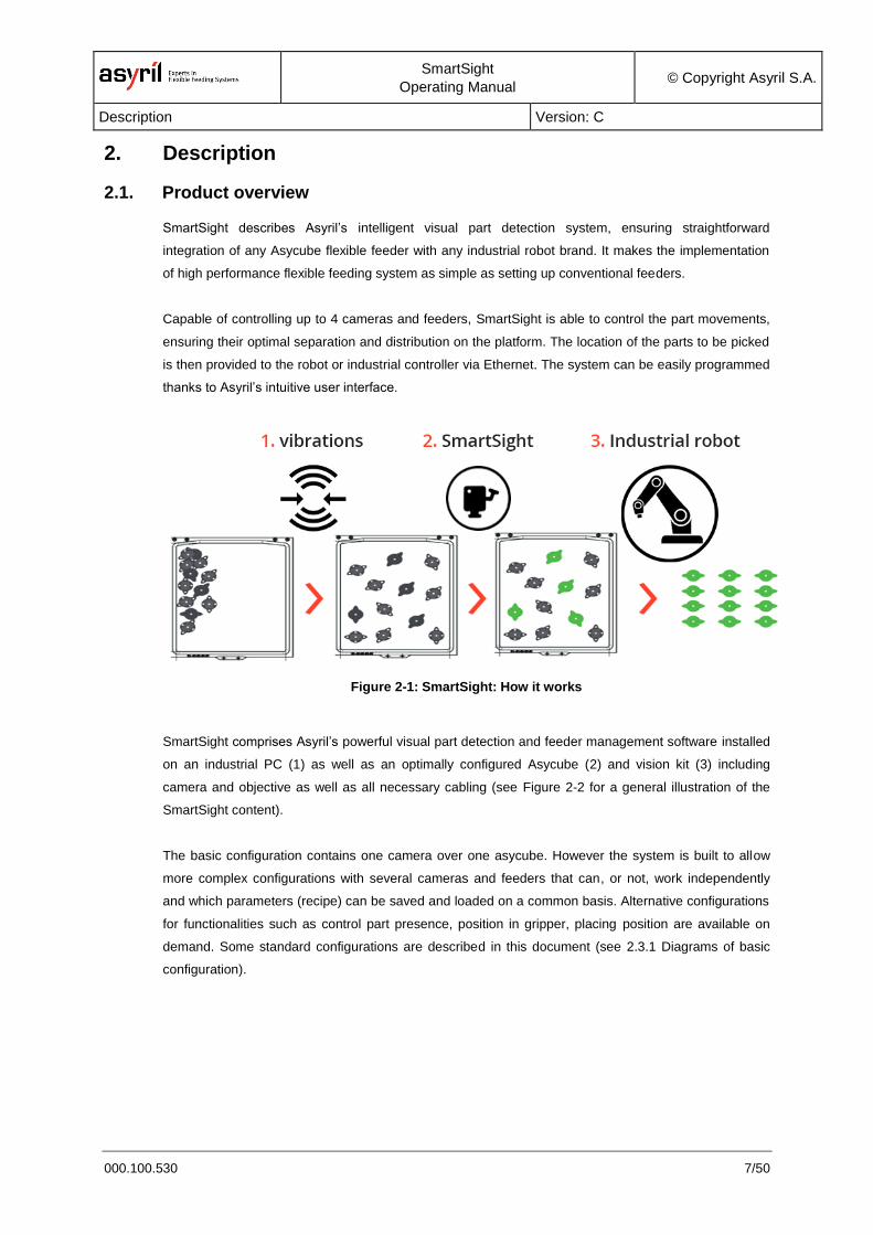
SmartSight describes Asyril’s intelligent visual part detection system, ensuring straightforward
integration of any Asycube flexible feeder with any industrial robot brand. It makes the implementation
of high performance flexible feeding system as simple as setting up conventional feeders.
Capable of controlling up to 4 cameras and feeders, SmartSight is able to control the part movements,
ensuring their optimal separation and distribution on the platform. The location of the parts to be picked
is then provided to the robot or industrial controller via Ethernet. The system can be easily programmed
thanks to Asyril’s intuitive user interface.
Figure 2-1: SmartSight: How it works
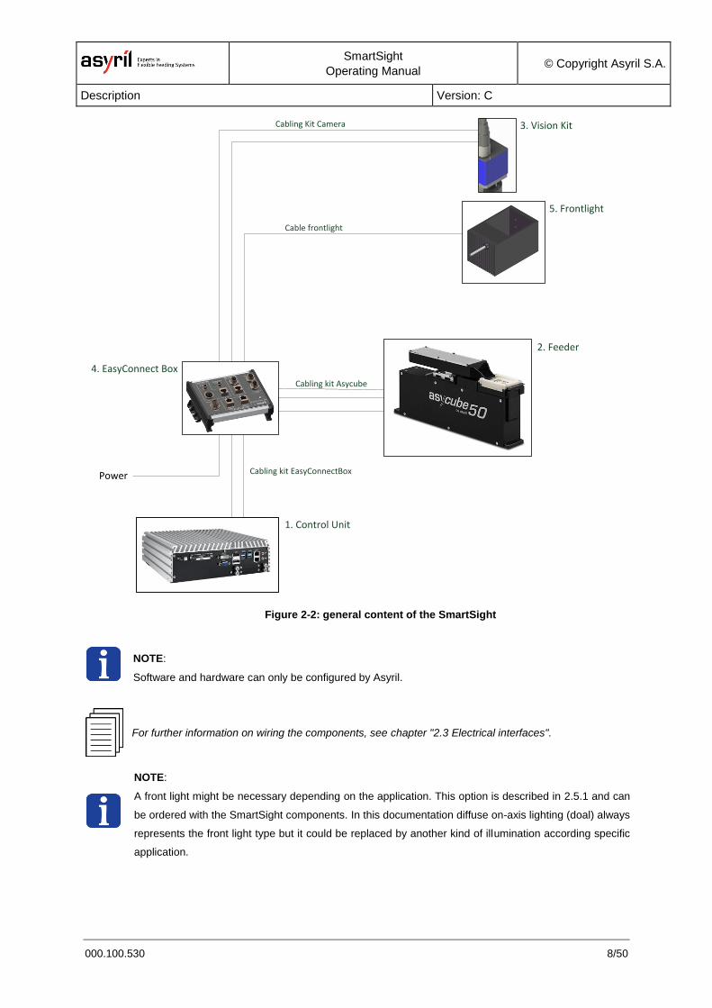
SmartSight comprises Asyril’s powerful visual part detection and feeder management software installed
on an industrial PC (1) as well as an optimally configured Asycube (2) and vision kit (3) including
camera and objective as well as all necessary cabling (see Figure 2-2 for a general illustration of the
SmartSight content).
The basic configuration contains one camera over one asycube. However the system is built to allow
more complex configurations with several cameras and feeders that can, or not, work independently
and which parameters (recipe) can be saved and loaded on a common basis. Alternative configurations
for functionalities such as control part presence, position in gripper, placing position are available on
demand. Some standard configurations are described in this document (see 2.3.1 Diagrams of basic
configuration).
SmartSight
Operating Manual © Copyright Asyril S.A.
Description Version: C
000.100.530 8/50
Power
1. Control Unit
5. Frontlight
3. Vision Kit
4. EasyConnect Box
Cabling Kit Camera
Cable frontlight
Cabling kit Asycube
Cabling kit EasyConnectBox
2. Feeder
Figure 2-2: general content of the SmartSight
NOTE:
Software and hardware can only be configured by Asyril.
For further information on wiring the components, see chapter "2.3 Electrical interfaces".
NOTE:
A front light might be necessary depending on the application. This option is described in 2.5.1 and can
be ordered with the SmartSight components. In this documentation diffuse on-axis lighting (doal) always
represents the front light type but it could be replaced by another kind of illumination according specific
application.
SmartSight
Operating Manual © Copyright Asyril S.A.
Description Version: C
000.100.530 9/50
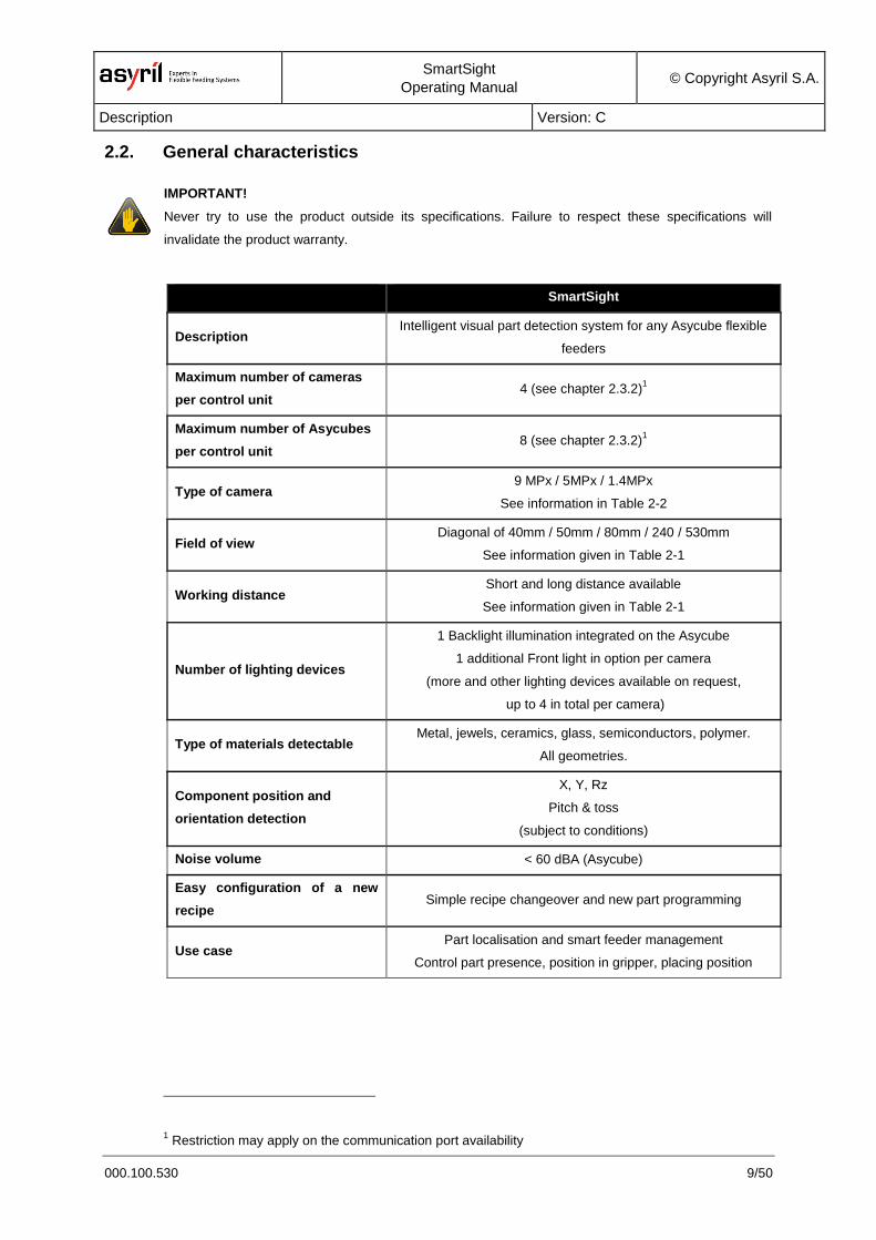
2.2. General characteristics
IMPORTANT!
Never try to use the product outside its specifications. Failure to respect these specifications will
invalidate the product warranty.
SmartSight
Description Intelligent visual part detection system for any Asycube flexible
feeders
Maximum number of cameras
per control unit 4 (see chapter 2.3.2)
1
Maximum number of Asycubes
per control unit 8 (see chapter 2.3.2)
1
Type of camera 9 MPx / 5MPx / 1.4MPx
See information in Table 2-2
Field of view Diagonal of 40mm / 50mm / 80mm / 240 / 530mm
See information given in Table 2-1
Working distance Short and long distance available
See information given in Table 2-1
Number of lighting devices
1 Backlight illumination integrated on the Asycube
1 additional Front light in option per camera
(more and other lighting devices available on request,
up to 4 in total per camera)
Type of materials detectable Metal, jewels, ceramics, glass, semiconductors, polymer.
All geometries.
Component position and
orientation detection
X, Y, Rz
Pitch & toss
(subject to conditions)
Noise volume < 60 dBA (Asycube)
Easy configuration of a new
recipe Simple recipe changeover and new part programming
Use case Part localisation and smart feeder management
Control part presence, position in gripper, placing position
1 Restriction may apply on the communication port availability
SmartSight
Operating Manual © Copyright Asyril S.A.
Description Version: C
000.100.530 10/50
2.2.1. Vision specifications
2.2.1.1. Standard Vision Kits
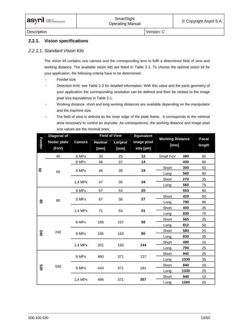
The vision kit contains one camera and the corresponding lens to fulfil a determined field of view and
working distance. The available vision kits are listed in Table 2-1. To choose the optimal vision kit for
your application, the following criteria have to be determined:
- Feeder size
- Detection limit: see Table 2-3 for detailed information. With this value and the parts geometry of
your application the corresponding resolution can be defined and then be related to the image
pixel size equivalence in Table 2-1.
- Working distance: short and long working distances are available depending on the manipulator
and the machine size.
- The field of view is defined as the inner edge of the plate frame. It corresponds to the minimal
area necessary to control an asycube. As consequences, the working distance and image pixel
size values are the minimal ones.
Fe
ed
er
Diagonal of
feeder plate
(FoV)
Camera
Field of View Equivalent
image pixel
size [µm]
Working Distance
[mm]
Focal
length Hauteur
[mm]
Largeur
[mm]
50
40 5 MPx 30 25 12 Small FoV 380 90
50
9 MPx 46 37 14 400 90
5 MPx 46 38 19 Short 300 50
Long 560 90
1,4 MPx 47 35 34 Short 270 35
Long 560 75
80
80
9 MPx 67 54 20 553 90
5 MPx 67 56 27 Short 420 50
Long 790 90
1,4 MPx 71 53 51 Short 400 35
Long 830 75
24
0
240
9 MPx 195 157 58 Short 565 35
Long 812 50
5 MPx 195 163 80 Short 580 25
Long 830 35
1,4 MPx 201 150 144 Short 490 16
Long 790 25
53
0
530
9 MPx 460 371 137 Short 940 25
Long 1330 35
5 MPx 443 371 181 Short 840 16
Long 1330 25
1,4 MPx 496 371 357 Short 940 12
Long 1260 25
SmartSight
Operating Manual © Copyright Asyril S.A.
Description Version: C
000.100.530 11/50
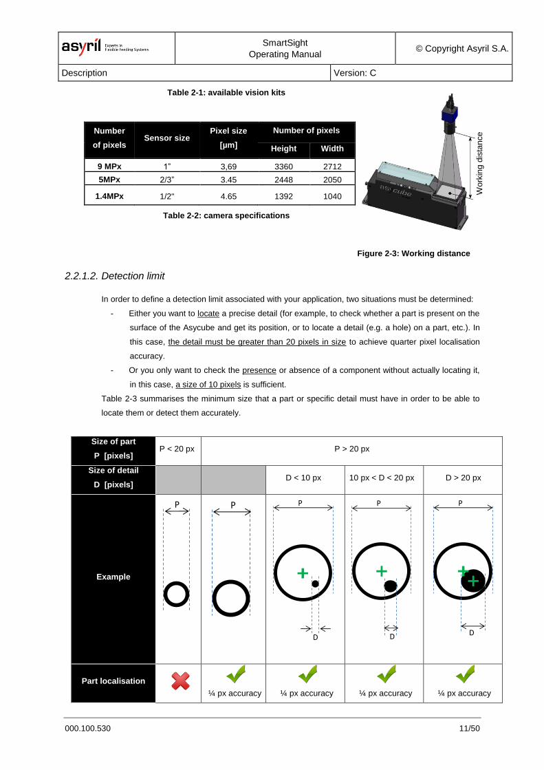
Figure 2-3: Working distance
definition
Table 2-1: available vision kits
Number
of pixels Sensor size
Pixel size
[µm]
Number of pixels
Height Width
9 MPx 1” 3,69 3360 2712
5MPx 2/3” 3.45 2448 2050
1.4MPx 1/2" 4.65 1392 1040
Table 2-2: camera specifications
2.2.1.2. Detection limit
In order to define a detection limit associated with your application, two situations must be determined:
- Either you want to locate a precise detail (for example, to check whether a part is present on the
surface of the Asycube and get its position, or to locate a detail (e.g. a hole) on a part, etc.). In
this case, the detail must be greater than 20 pixels in size to achieve quarter pixel localisation
accuracy.
- Or you only want to check the presence or absence of a component without actually locating it,
in this case, a size of 10 pixels is sufficient.
Table 2-3 summarises the minimum size that a part or specific detail must have in order to be able to
locate them or detect them accurately.
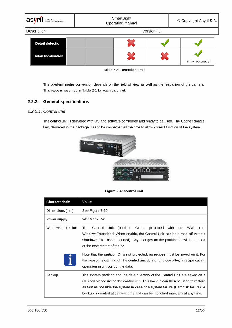
Size of part
P [pixels] P < 20 px P > 20 px
Size of detail
D [pixels] D < 10 px 10 px < D < 20 px D > 20 px
Example
Part localisation
¼ px accuracy
¼ px accuracy
¼ px accuracy
¼ px accuracy
P P P
D
P
D
P
D
Work
ing
dis
tan
ce
SmartSight
Operating Manual © Copyright Asyril S.A.
Description Version: C
000.100.530 12/50
Detail detection
Detail localisation
¼ px accuracy
Table 2-3: Detection limit
The pixel-millimetre conversion depends on the field of view as well as the resolution of the camera.
This value is resumed in Table 2-1 for each vision kit.
2.2.2. General specifications
2.2.2.1. Control unit
The control unit is delivered with OS and software configured and ready to be used. The Cognex dongle
key, delivered in the package, has to be connected all the time to allow correct function of the system.
Figure 2-4: control unit
Characteristic Value
Dimensions [mm] See Figure 2-20
Power supply 24VDC / 75 W
Windows protection
The Control Unit (partition C) is protected with the EWF from
WindowsEmbedded. When enable, the Control Unit can be turned off without
shutdown (No UPS is needed). Any changes on the partition C: will be erased
at the next restart of the pc.
Note that the partition D: is not protected, as recipes must be saved on it. For
this reason, switching off the control unit during, or close after, a recipe saving
operation might corrupt the data.
Backup The system partition and the data directory of the Control Unit are saved on a
CF card placed inside the control unit. This backup can then be used to restore
as fast as possible the system in case of a system failure (Harddisk failure). A
backup is created at delivery time and can be launched manually at any time.
SmartSight
Operating Manual © Copyright Asyril S.A.
Description Version: C
000.100.530 13/50
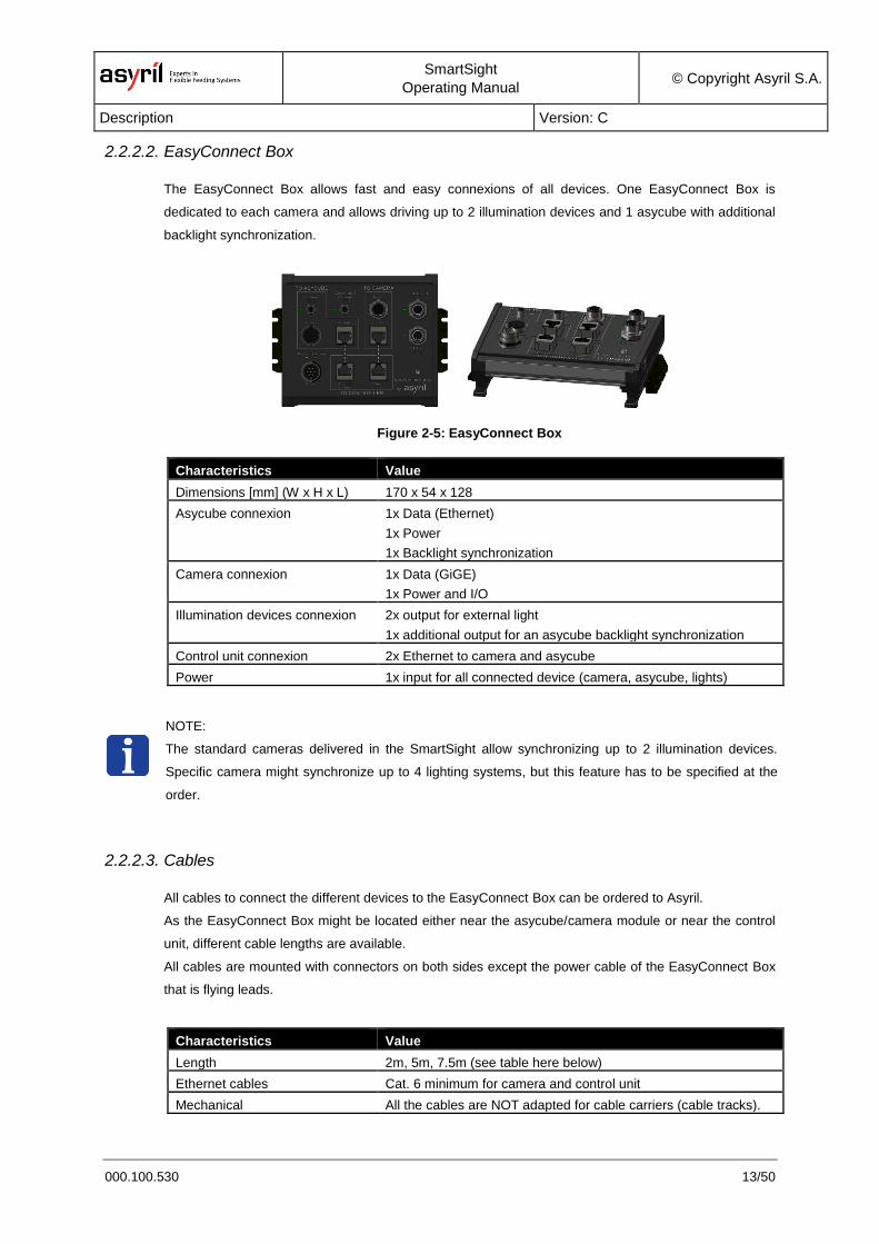
2.2.2.2. EasyConnect Box
The EasyConnect Box allows fast and easy connexions of all devices. One EasyConnect Box is
dedicated to each camera and allows driving up to 2 illumination devices and 1 asycube with additional
backlight synchronization.
Figure 2-5: EasyConnect Box
Characteristics Value
Dimensions [mm] (W x H x L) 170 x 54 x 128
Asycube connexion 1x Data (Ethernet)
1x Power
1x Backlight synchronization
Camera connexion 1x Data (GiGE)
1x Power and I/O
Illumination devices connexion 2x output for external light
1x additional output for an asycube backlight synchronization
Control unit connexion 2x Ethernet to camera and asycube
Power 1x input for all connected device (camera, asycube, lights)
NOTE:
The standard cameras delivered in the SmartSight allow synchronizing up to 2 illumination devices.
Specific camera might synchronize up to 4 lighting systems, but this feature has to be specified at the
order.
2.2.2.3. Cables
All cables to connect the different devices to the EasyConnect Box can be ordered to Asyril.
As the EasyConnect Box might be located either near the asycube/camera module or near the control
unit, different cable lengths are available.
All cables are mounted with connectors on both sides except the power cable of the EasyConnect Box
that is flying leads.
Characteristics Value
Length 2m, 5m, 7.5m (see table here below)
Ethernet cables Cat. 6 minimum for camera and control unit
Mechanical All the cables are NOT adapted for cable carriers (cable tracks).
SmartSight
Operating Manual © Copyright Asyril S.A.
Description Version: C
000.100.530 14/50
Available lengths 2m 5m 7.5m
Cable kit Asycube x x
Cable kit Camera x x x
Cable Frontlight x x x
Cable kit EasyConnect Box x x x
NOTE:
No power supply is delivered with the SmartSight: 24VDC has to be connected to each EasyConnect
Box and to the Control Unit (no cable is provided with the control unit but its connector, the cable has to
be screwed on the connector by the integrator).
For further information on wiring the components, see chapter "2.3 Electrical interfaces".
For further information on dimensions, see chapter “2.4 Mechanical interfaces”
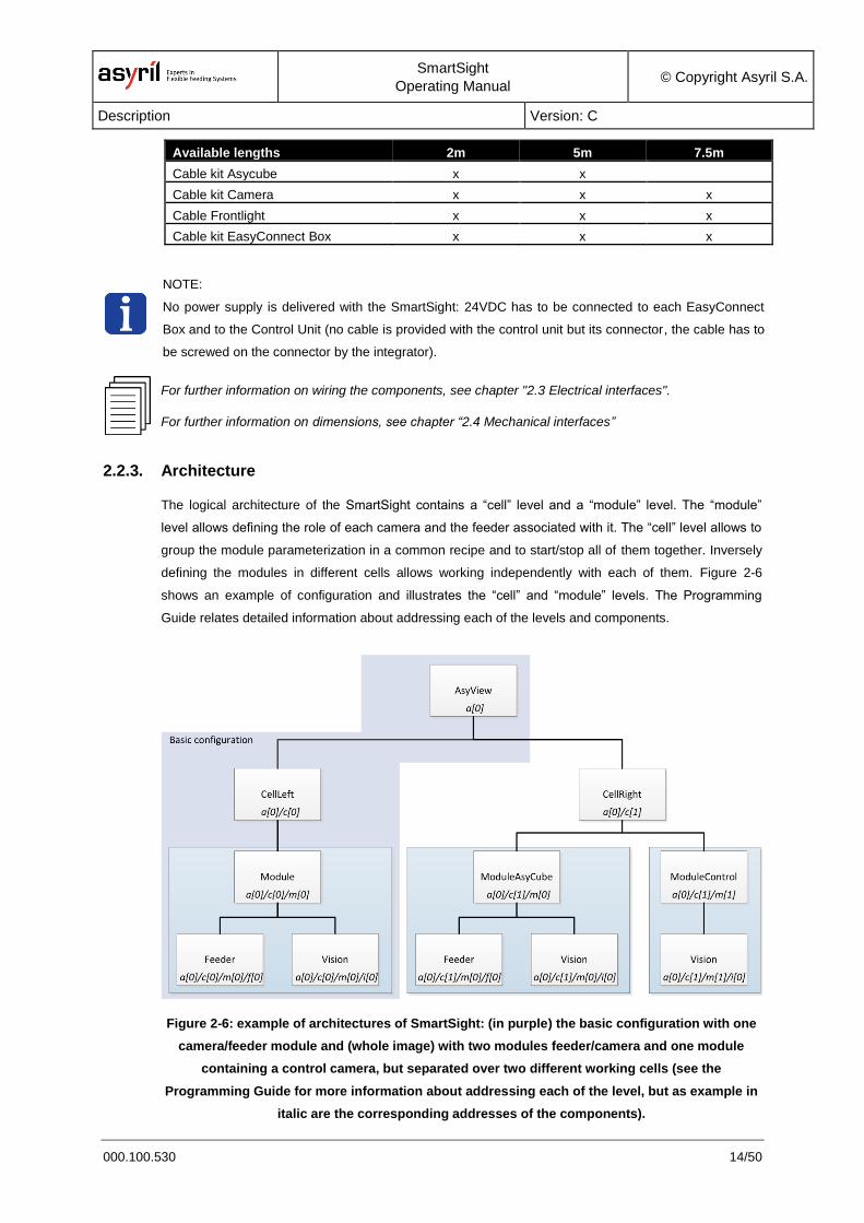
2.2.3. Architecture
The logical architecture of the SmartSight contains a “cell” level and a “module” level. The “module”
level allows defining the role of each camera and the feeder associated with it. The “cell” level allows to
group the module parameterization in a common recipe and to start/stop all of them together. Inversely
defining the modules in different cells allows working independently with each of them. Figure 2-6
shows an example of configuration and illustrates the “cell” and “module” levels. The Programming
Guide relates detailed information about addressing each of the levels and components.
Figure 2-6: example of architectures of SmartSight: (in purple) the basic configuration with one
camera/feeder module and (whole image) with two modules feeder/camera and one module
containing a control camera, but separated over two different working cells (see the
Programming Guide for more information about addressing each of the level, but as example in
italic are the corresponding addresses of the components).

SmartSight
Operating Manual © Copyright Asyril S.A.
Description Version: C
000.100.530 15/50
SmartSight
Operating Manual © Copyright Asyril S.A.
Description Version: C
000.100.530 16/50
2.3. Electrical interfaces
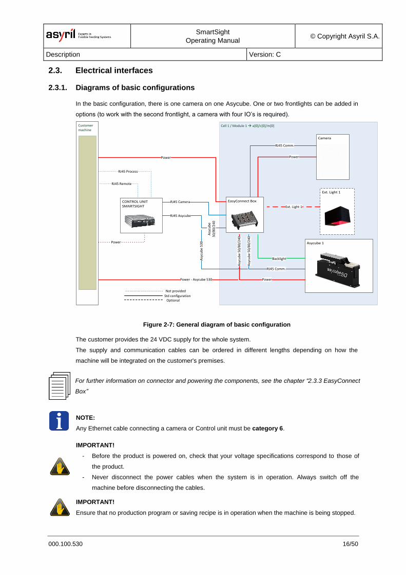
2.3.1. Diagrams of basic configurations
In the basic configuration, there is one camera on one Asycube. One or two frontlights can be added in
options (to work with the second frontlight, a camera with four IO’s is required).
Cell 1 / Module 1 à a[0]/c[0]/m[0]
Asycube 1
Camera
Ext. Light 1
Customer machine
EasyConnect Box
RJ45 Comm.
RJ45 Comm.
RJ45 Asycube
RJ45 Camera
Power
Power
Backlight
Power
Power
RJ45 Remote
RJ45 Process
Not provided
Std configurationOptional
Ext. Light 1
Asy
cub
e 5
30
Power - Asycube 530
Asy
cub
e 5
0/8
0/2
40
Asy
cub
e 5
0/8
0/2
40
Asy
cub
e5
0/8
0/2
40
CONTROL UNIT SMARTSIGHT
Figure 2-7: General diagram of basic configuration
The customer provides the 24 VDC supply for the whole system.
The supply and communication cables can be ordered in different lengths depending on how the
machine will be integrated on the customer's premises.
For further information on connector and powering the components, see the chapter “2.3.3 EasyConnect
Box”
NOTE:
Any Ethernet cable connecting a camera or Control unit must be category 6.
IMPORTANT!
- Before the product is powered on, check that your voltage specifications correspond to those of
the product.
- Never disconnect the power cables when the system is in operation. Always switch off the
machine before disconnecting the cables.
IMPORTANT!
Ensure that no production program or saving recipe is in operation when the machine is being stopped.
SmartSight
Operating Manual © Copyright Asyril S.A.
Description Version: C
000.100.530 17/50
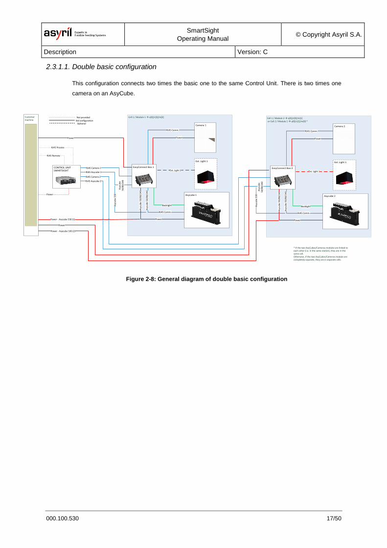
2.3.1.1. Double basic configuration
This configuration connects two times the basic one to the same Control Unit. There is two times one
camera on an AsyCube.
Cell 1 / Module 1 à a[0]/c[0]/m[0] Cell 1 / Module 2 à a[0]/c[0]/m[1] or Cell 2 / Module 1 à a[0]/c[1]/m[0] *
Asycube 1
Camera 1
Ext. Light 1
Customer machine
EasyConnect Box 1
Asycube 2
Camera 2
Ext. Light 1
EasyConnect Box 2
RJ45 Camera 2
RJ45 Comm.
RJ45 Comm.
RJ45 Asycube 1
RJ45 Camera 1
Power
Power
Backlight
Power
Power
RJ45 Remote
RJ45 Process
Not provided
Std configurationOptional
Ext. Light 1
Asy
cub
e 5
30
Power - Asycube 530 (1)
Asy
cub
e 5
0/8
0/2
40
Asy
cub
e 5
0/8
0/2
40
Asy
cub
e5
0/8
0/2
40
Power
RJ45 Comm.
RJ45 Comm.
Power
Power
Backlight
Ext. Light 1
Asy
cub
e 5
0/8
0/2
40
Asy
cub
e 5
0/8
0/2
40
RJ45 Asycube 2
Asy
cub
e5
0/8
0/2
40
Asy
cub
e 5
30
Power - Asycube 530 (2)
* If the two AsyCubes/Cameras modules are linked to each other (i.e. in the same station), they are in the same cell.Otherwise, if the two AsyCubes/Cameras module are completely separate, they are in separate cells.
CONTROL UNIT SMARTSIGHT
Figure 2-8: General diagram of double basic configuration
SmartSight
Operating Manual © Copyright Asyril S.A.
Description Version: C
000.100.530 18/50
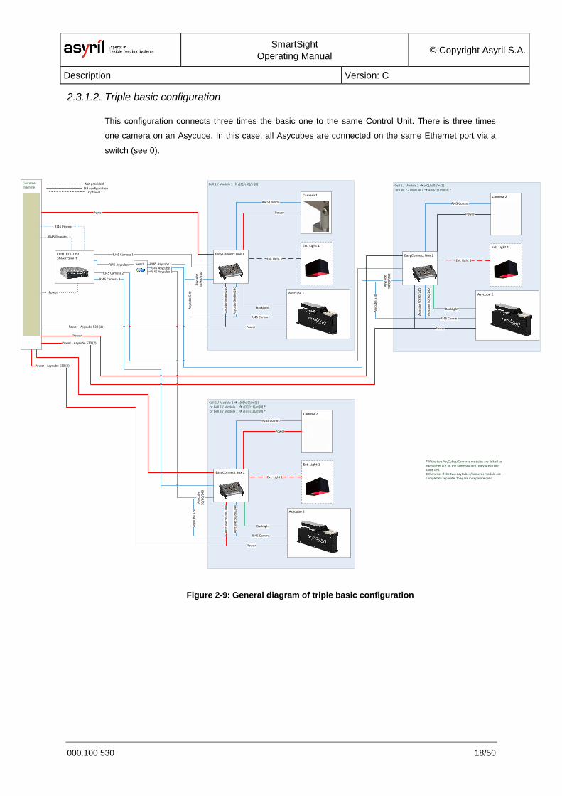
2.3.1.2. Triple basic configuration
This configuration connects three times the basic one to the same Control Unit. There is three times
one camera on an Asycube. In this case, all Asycubes are connected on the same Ethernet port via a
switch (see 0).
Cell 1 / Module 2 à a[0]/c[0]/m[1] or Cell 2 / Module 1 à a[0]/c[1]/m[0] * or Cell 3 / Module 1 à a[0]/c[2]/m[0] *
Cell 1 / Module 1 à a[0]/c[0]/m[0] Cell 1 / Module 2 à a[0]/c[0]/m[1] or Cell 2 / Module 1 à a[0]/c[1]/m[0] *
Asycube 1
Camera 1
Ext. Light 1
Customer machine
EasyConnect Box 1
Asycube 2
Camera 2
Ext. Light 1
EasyConnect Box 2
Asycube 2
Camera 2
Ext. Light 1
EasyConnect Box 2
RJ45 Camera 2
RJ45 Comm.
RJ45 Comm.
RJ45 Asycube 1
RJ45 Camera 1
Power
Power
Backlight
Power
Power
RJ45 Remote
RJ45 Process
Not provided
Std configurationOptional
Ext. Light 1
Asy
cub
e 5
30
Power - Asycube 530 (1)
Asy
cub
e 5
0/8
0/2
40
Asy
cub
e 5
0/8
0/2
40
Asy
cub
e5
0/8
0/2
40
CONTROL UNIT SMARTSIGHT
Power
RJ45 Comm.
RJ45 Comm.
Power
Power
Backlight
Ext. Light 1
Asy
cub
e 5
0/8
0/2
40
Asy
cub
e 5
0/8
0/2
40
RJ45 Asycube 2
Asy
cub
e5
0/8
0/2
40
Asy
cub
e 5
30
Power - Asycube 530 (2)
* If the two AsyCubes/Cameras modules are linked to each other (i.e. in the same station), they are in the same cell.Otherwise, if the two AsyCubes/Cameras module are completely separate, they are in separate cells.
RJ45 Comm.
RJ45 Comm.
Power
Power
Backlight
Ext. Light 1
Asy
cub
e 5
0/8
0/2
40
Asy
cub
e 5
0/8
0/2
40
Asy
cub
e 5
30
SwitchRJ45 Asycubes
RJ45 Asycube 3
Asy
cub
e5
0/8
0/2
40
Power - Asycube 530 (3)
RJ45 Camera 3
Figure 2-9: General diagram of triple basic configuration
SmartSight
Operating Manual © Copyright Asyril S.A.
Description Version: C
000.100.530 19/50
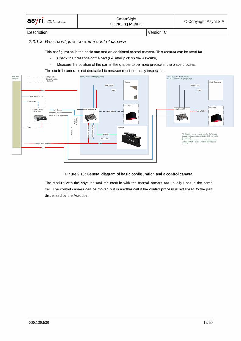
2.3.1.3. Basic configuration and a control camera
This configuration is the basic one and an additional control camera. This camera can be used for:
- Check the presence of the part (i.e. after pick on the Asycube)
- Measure the position of the part in the gripper to be more precise in the place process.
The control camera is not dedicated to measurement or quality inspection.
Cell 1 / Module 1 à a[0]/c[0]/m[0] Cell 1 / Module 2 à a[0]/c[0]/m[1] or Cell 2 / Module 1 à a[0]/c[1]/m[0] *
Asycube 1
Camera
Ext. Light 1
Customer machine
EasyConnect Box
Control camera
Ext. Light 1
Ext. Light 1
* If the control camera is used linked to the Asycube module (i.e. to control the part after pick), they are in the same cell.Otherwise, if the control camera is used completely without link to the Asycube module, they are in his own cell.
RJ45 Control camera
RJ45 Comm.
RJ45 Comm.
RJ45 Asycube
RJ45 Camera
Power
Power
Backlight
Power
Power
RJ45 Remote
RJ45 Process
Not provided
Std configurationOptional
Ext. Light 1
Asy
cub
e 5
30
Power - Asycube 530
Asy
cub
e 5
0/8
0/2
40
Asy
cub
e 5
0/8
0/2
40
Asy
cub
e5
0/8
0/2
40
CONTROL UNIT SMARTSIGHT
EasyConnect Box
Power
RJ45 Comm.
Power
Figure 2-10: General diagram of basic configuration and a control camera
The module with the Asycube and the module with the control camera are usually used in the same
cell. The control camera can be moved out in another cell if the control process is not linked to the part
dispensed by the Asycube.
SmartSight
Operating Manual © Copyright Asyril S.A.
Description Version: C
000.100.530 20/50
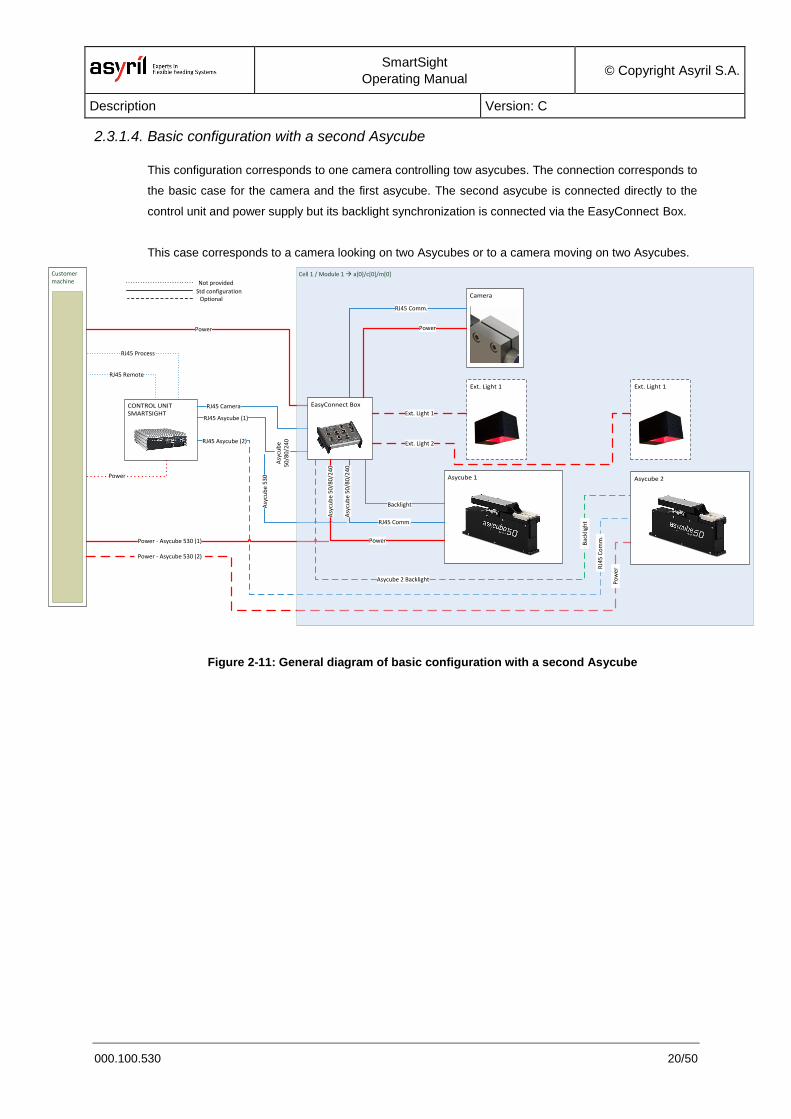
2.3.1.4. Basic configuration with a second Asycube
This configuration corresponds to one camera controlling tow asycubes. The connection corresponds to
the basic case for the camera and the first asycube. The second asycube is connected directly to the
control unit and power supply but its backlight synchronization is connected via the EasyConnect Box.
This case corresponds to a camera looking on two Asycubes or to a camera moving on two Asycubes.
Customer machine
RJ45 Asycube (1)
RJ45 Camera
Power
Power
RJ45 Remote
RJ45 Process
Not provided
Std configurationOptional
Asy
cub
e 5
30
Power - Asycube 530 (1)
Asy
cub
e5
0/8
0/2
40
CONTROL UNIT SMARTSIGHT
RJ45 Asycube (2)
Power - Asycube 530 (2)
Cell 1 / Module 1 à a[0]/c[0]/m[0]
Asycube 1
Camera
Ext. Light 1
EasyConnect Box
Ext. Light 1
Asycube 2
RJ45 Comm.
RJ45 Comm.
Power
Power
Backlight
Ext. Light 1
Asy
cub
e 5
0/8
0/2
40
Asy
cub
e 5
0/8
0/2
40
Ext. Light 2
Asycube 2 BacklightB
ackl
igh
t
RJ4
5 C
om
m.
Po
wer
Figure 2-11: General diagram of basic configuration with a second Asycube
SmartSight
Operating Manual © Copyright Asyril S.A.
Description Version: C
000.100.530 21/50
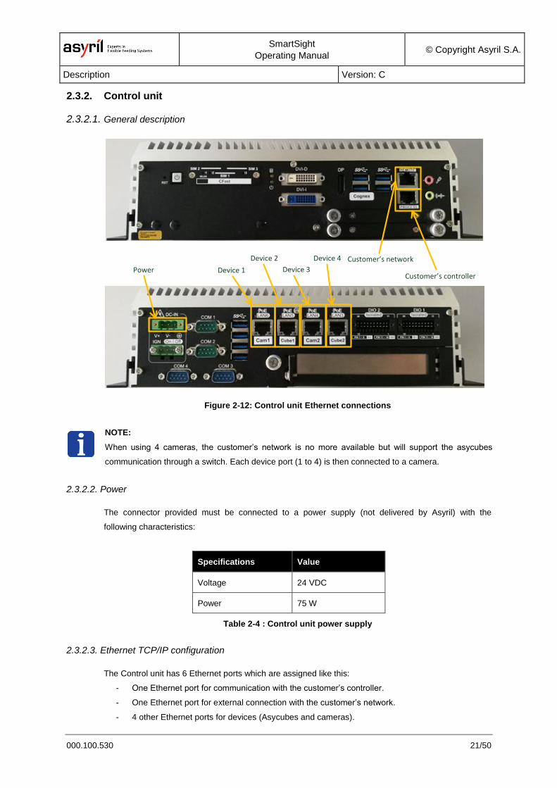
2.3.2. Control unit
2.3.2.1. General description
Customer’s controller
Customer’s network
Device 1Power
Device 2
Device 3
Device 4
Figure 2-12: Control unit Ethernet connections
NOTE:
When using 4 cameras, the customer’s network is no more available but will support the asycubes
communication through a switch. Each device port (1 to 4) is then connected to a camera.
2.3.2.2. Power
The connector provided must be connected to a power supply (not delivered by Asyril) with the
following characteristics:
Specifications Value
Voltage 24 VDC
Power 75 W
Table 2-4 : Control unit power supply
2.3.2.3. Ethernet TCP/IP configuration
The Control unit has 6 Ethernet ports which are assigned like this:
- One Ethernet port for communication with the customer’s controller.
- One Ethernet port for external connection with the customer’s network.
- 4 other Ethernet ports for devices (Asycubes and cameras).
SmartSight
Operating Manual © Copyright Asyril S.A.
Description Version: C
000.100.530 22/50
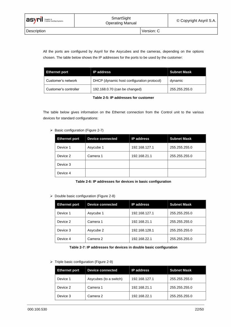
All the ports are configured by Asyril for the Asycubes and the cameras, depending on the options
chosen. The table below shows the IP addresses for the ports to be used by the customer:
Ethernet port IP address Subnet Mask
Customer’s network DHCP (dynamic host configuration protocol) dynamic
Customer’s controller 192.168.0.70 (can be changed) 255.255.255.0
Table 2-5: IP addresses for customer
The table below gives information on the Ethernet connection from the Control unit to the various
devices for standard configurations:
Basic configuration (Figure 2-7)
Ethernet port Device connected IP address Subnet Mask
Device 1 Asycube 1 192.168.127.1 255.255.255.0
Device 2 Camera 1 192.168.21.1 255.255.255.0
Device 3
Device 4
Table 2-6: IP addresses for devices in basic configuration
Double basic configuration (Figure 2-8)
Ethernet port Device connected IP address Subnet Mask
Device 1 Asycube 1 192.168.127.1 255.255.255.0
Device 2 Camera 1 192.168.21.1 255.255.255.0
Device 3 Asycube 2 192.168.128.1 255.255.255.0
Device 4 Camera 2 192.168.22.1 255.255.255.0
Table 2-7: IP addresses for devices in double basic configuration
Triple basic configuration (Figure 2-9)
Ethernet port Device connected IP address Subnet Mask
Device 1 Asycubes (to a switch) 192.168.127.1 255.255.255.0
Device 2 Camera 1 192.168.21.1 255.255.255.0
Device 3 Camera 2 192.168.22.1 255.255.255.0
SmartSight
Operating Manual © Copyright Asyril S.A.
Description Version: C
000.100.530 23/50
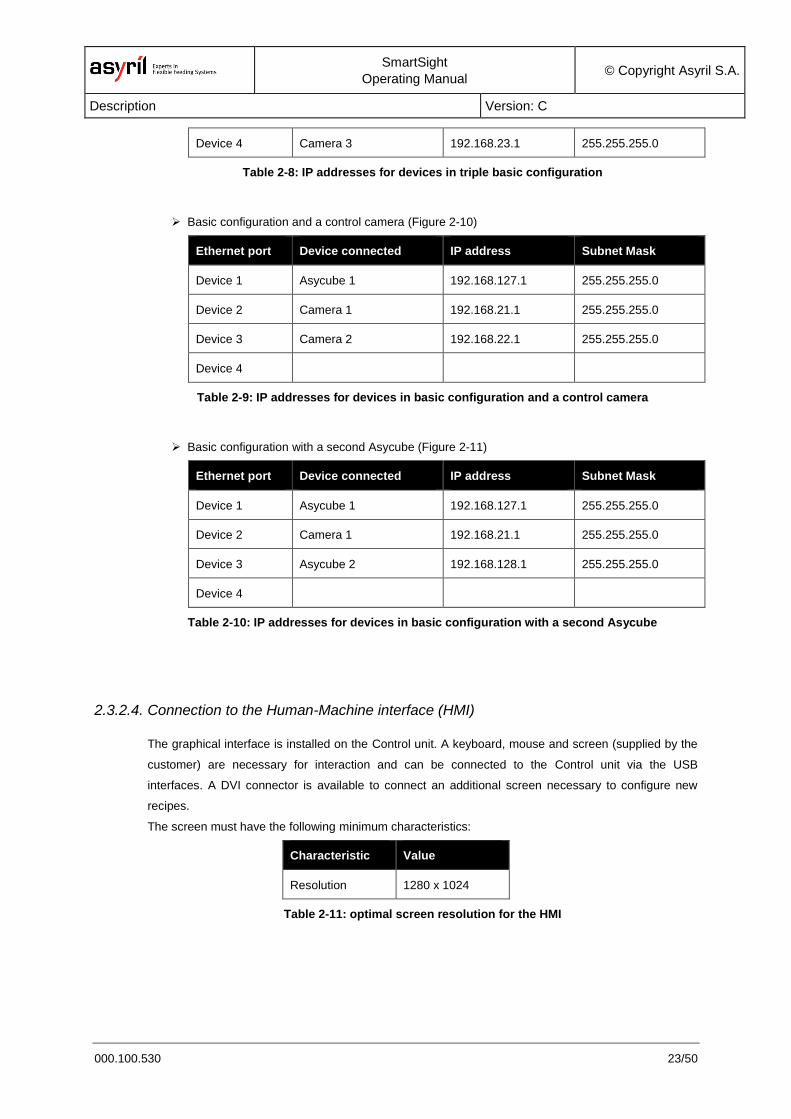
Device 4 Camera 3 192.168.23.1 255.255.255.0
Table 2-8: IP addresses for devices in triple basic configuration
Basic configuration and a control camera (Figure 2-10)
Ethernet port Device connected IP address Subnet Mask
Device 1 Asycube 1 192.168.127.1 255.255.255.0
Device 2 Camera 1 192.168.21.1 255.255.255.0
Device 3 Camera 2 192.168.22.1 255.255.255.0
Device 4
Table 2-9: IP addresses for devices in basic configuration and a control camera
Basic configuration with a second Asycube (Figure 2-11)
Ethernet port Device connected IP address Subnet Mask
Device 1 Asycube 1 192.168.127.1 255.255.255.0
Device 2 Camera 1 192.168.21.1 255.255.255.0
Device 3 Asycube 2 192.168.128.1 255.255.255.0
Device 4
Table 2-10: IP addresses for devices in basic configuration with a second Asycube
2.3.2.4. Connection to the Human-Machine interface (HMI)
The graphical interface is installed on the Control unit. A keyboard, mouse and screen (supplied by the
customer) are necessary for interaction and can be connected to the Control unit via the USB
interfaces. A DVI connector is available to connect an additional screen necessary to configure new
recipes.
The screen must have the following minimum characteristics:
Characteristic Value
Resolution 1280 x 1024
Table 2-11: optimal screen resolution for the HMI
SmartSight
Operating Manual © Copyright Asyril S.A.
Description Version: C
000.100.530 24/50
2.3.3. EasyConnect Box
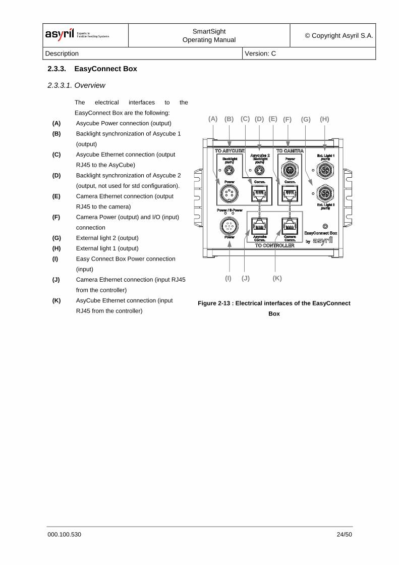
2.3.3.1. Overview
The electrical interfaces to the
EasyConnect Box are the following:
(A) Asycube Power connection (output)
(B) Backlight synchronization of Asycube 1
(output)
(C) Asycube Ethernet connection (output
RJ45 to the AsyCube)
(D) Backlight synchronization of Asycube 2
(output, not used for std configuration).
(E) Camera Ethernet connection (output
RJ45 to the camera)
(F) Camera Power (output) and I/O (input)
connection
(G) External light 2 (output)
(H) External light 1 (output)
(I) Easy Connect Box Power connection
(input)
(J) Camera Ethernet connection (input RJ45
from the controller)
(K) AsyCube Ethernet connection (input
RJ45 from the controller)
Figure 2-13 : Electrical interfaces of the EasyConnect
Box
(J)
(B) (D) (F) (G)
(I) (K)
(H) (A) (C) (E)
SmartSight
Operating Manual © Copyright Asyril S.A.
Description Version: C
000.100.530 25/50
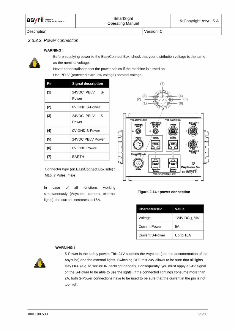
2.3.3.2. Power connection
WARNING !
- Before supplying power to the EasyConnect Box, check that your distribution voltage is the same
as the nominal voltage.
- Never connect/disconnect the power cables if the machine is turned on.
- Use PELV (protected extra-low voltage) nominal voltage.
Pin Signal description
(1) 24VDC PELV S-
Power
(2) 0V GND S-Power
(3) 24VDC PELV S-
Power
(4) 0V GND S-Power
(5) 24VDC PELV Power
(6) 0V GND Power
(7) EARTH
Connector type (on EasyConnect Box side) :
M16, 7 Poles, male
In case of all functions working
simultaneously (Asycube, camera, external
lights), the current increases to 15A.
Figure 2-14 : power connection
Characteristic Value
Voltage +24V DC + 5%
Current Power 5A
Current S-Power Up to 10A
WARNING !
- S-Power is the safety power. This 24V supplies the Asycube (see the documentation of the
Asycube) and the external lights. Switching OFF this 24V allows to be sure that all lights
stay OFF (e.g. to secure IR backlight danger). Consequently, you must apply a 24V signal
on the S-Power to be able to use the lights. If the connected lightings consume more than
2A, both S-Power connections have to be used to be sure that the current in the pin is not
too high.
(5)
(6)
(2)
(1)
(3) (4)
(7)
SmartSight
Operating Manual © Copyright Asyril S.A.
Description Version: C
000.100.530 26/50
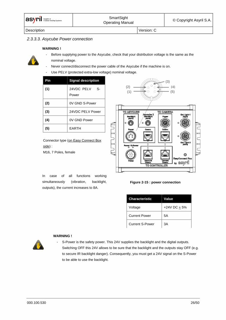
2.3.3.3. Asycube Power connection
WARNING !
- Before supplying power to the Asycube, check that your distribution voltage is the same as the
nominal voltage.
- Never connect/disconnect the power cable of the Asycube if the machine is on.
- Use PELV (protected extra-low voltage) nominal voltage.
Pin Signal description
(1) 24VDC PELV S-
Power
(2) 0V GND S-Power
(3) 24VDC PELV Power
(4) 0V GND Power
(5) EARTH
Connector type (on Easy Connect Box
side) :
M16, 7 Poles, female
In case of all functions working
simultaneously (vibration, backlight,
outputs), the current increases to 8A.
Figure 2-15 : power connection
Characteristic Value
Voltage +24V DC + 5%
Current Power 5A
Current S-Power 3A
WARNING !
- S-Power is the safety power. This 24V supplies the backlight and the digital outputs.
Switching OFF this 24V allows to be sure that the backlight and the outputs stay OFF (e.g.
to secure IR backlight danger). Consequently, you must get a 24V signal on the S-Power
to be able to use the backlight.
(4)
(5)
(2)
(1)
(3)
SmartSight
Operating Manual © Copyright Asyril S.A.
Description Version: C
000.100.530 27/50
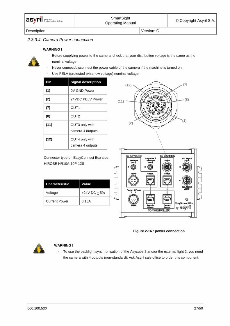
2.3.3.4. Camera Power connection
WARNING !
- Before supplying power to the camera, check that your distribution voltage is the same as the
nominal voltage.
- Never connect/disconnect the power cable of the camera if the machine is turned on.
- Use PELV (protected extra-low voltage) nominal voltage.
Pin Signal description
(1) 0V GND Power
(2) 24VDC PELV Power
(7) OUT1
(8) OUT2
(11) OUT3 only with
camera 4 outputs
(12) OUT4 only with
camera 4 outputs
Connector type on EasyConnect Box side:
HIROSE HR10A-10P-12S
Characteristic Value
Voltage +24V DC + 5%
Current Power 0.13A
Figure 2-16 : power connection
WARNING !
- To use the backlight synchronisation of the Asycube 2 and/or the external light 2, you need
the camera with 4 outputs (non-standard). Ask Asyril sale office to order this component.
(7)
(8)
(12)
(2) (1)
(11)
SmartSight
Operating Manual © Copyright Asyril S.A.
Description Version: C
000.100.530 28/50
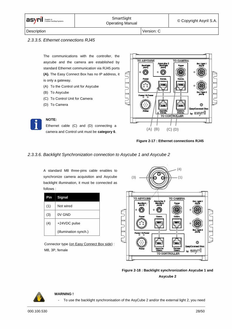
2.3.3.5. Ethernet connections RJ45
The communications with the controller, the
asycube and the camera are established by
standard Ethernet communication via RJ45 ports
(A). The Easy Connect Box has no IP address, it
is only a gateway.
(A) To the Control unit for Asycube
(B) To Asycube
(C) To Control Unit for Camera
(D) To Camera
NOTE:
Ethernet cable (C) and (D) connecting a
camera and Control unit must be category 6.
Figure 2-17 : Ethernet connections RJ45
2.3.3.6. Backlight Synchronization connection to Asycube 1 and Asycube 2
A standard M8 three-pins cable enables to
synchronize camera acquisition and Asycube
backlight illumination, it must be connected as
follows :
Pin Signal
(1) Not wired
(3) 0V GND
(4) +24VDC pulse
(illumination synch.)
Connector type (on Easy Connect Box side) :
M8, 3P, female
Figure 2-18 : Backlight synchronization Asycube 1 and
Asycube 2
WARNING !
- To use the backlight synchronisation of the AsyCube 2 and/or the external light 2, you need
(B) (A) (D) (C)
(3)
(4)
(1)

SmartSight
Operating Manual © Copyright Asyril S.A.
Description Version: C
000.100.530 29/50
a camera with 4 outputs (non-standard). Ask Asyril sale office to order this component.
2.3.3.7. External light 1 and 2 connections
A standard M12 4-pins cable enables to
connect to the external light, it must be
connected as follows :
Pin Signal
(1) 24VDC
S-Power (max. 3.5A)
(2) 0V GND S-Power
(3) 0V GND S-Power
(4) 24VDC pulse (max.3.5A)
(5) Not wired
Connector type (on EasyConnect Box side) :
M12, 5P, female
Figure 2-19 : External light 1 and 2
NOTE :
If the external light have a power connection and a command connection (4 wires), use pins 1 and 2 for the
power (3.5A max.) and 3 and 4 for the command.
If the external light have only a power/command signal (two wires), use the pins 3 and 4 (3.5A max.).
WARNING !
- To use the backlight synchronisation of the Asycube 2 and/or the external light 2, you need
a camera with 4 outputs (non-standard). Ask Asyril sale office to order this component.
(3)
(1)
(4)
(2)
(5)
SmartSight
Operating Manual © Copyright Asyril S.A.
Description Version: C
000.100.530 30/50
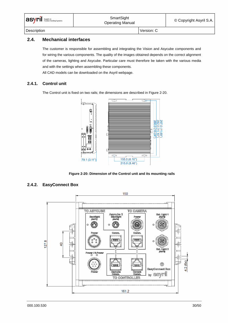
2.4. Mechanical interfaces
The customer is responsible for assembling and integrating the Vision and Asycube components and
for wiring the various components. The quality of the images obtained depends on the correct alignment
of the cameras, lighting and Asycube. Particular care must therefore be taken with the various media
and with the settings when assembling these components.
All CAD models can be downloaded on the Asyril webpage.
2.4.1. Control unit
The Control unit is fixed on two rails; the dimensions are described in Figure 2-20.
Figure 2-20: Dimension of the Control unit and its mounting rails
2.4.2. EasyConnect Box
SmartSight
Operating Manual © Copyright Asyril S.A.
Description Version: C
000.100.530 31/50
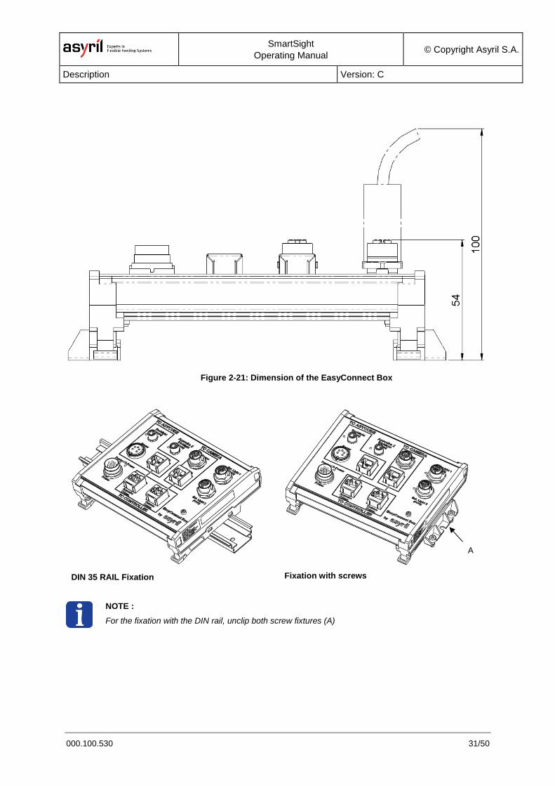
Figure 2-21: Dimension of the EasyConnect Box
DIN 35 RAIL Fixation
Fixation with screws
NOTE :
For the fixation with the DIN rail, unclip both screw fixtures (A)
A

SmartSight
Operating Manual © Copyright Asyril S.A.
Description Version: C
000.100.530 32/50
2.4.3. Vision Kit
The CAD model of the vision kit can be downloaded on the Asyril webpage. The method for integrating
the vision kit with the asycube is described in Figure 2-22.
Figure 2-22: Vision kit integration
WD
The 3D model of the vision kit is composed by the camera, objective
and the conus which represents the working distance (WD) and the
field of view (FoV). The lighting (L) is not part of the 3D vision kit, for
further information see 2.5.1.
Pay attention that the field of view is defined as the inner edge of the
plate frame.
The WD is the distance between the front face of the objective and
the asycube plate. The integrator ensures that the position of the
vision kit can be mechanically adjusted in a tolerance of -10mm/
+30mm.
For positioning the vision kit onto the asycube, place the face centre
of the conus (A) on the plate centre (B)
(A)
(B)
WD
-1
0/+
30
(L)

SmartSight
Operating Manual © Copyright Asyril S.A.
Description Version: C
000.100.530 33/50
Figure 2-23: Frontlight integration
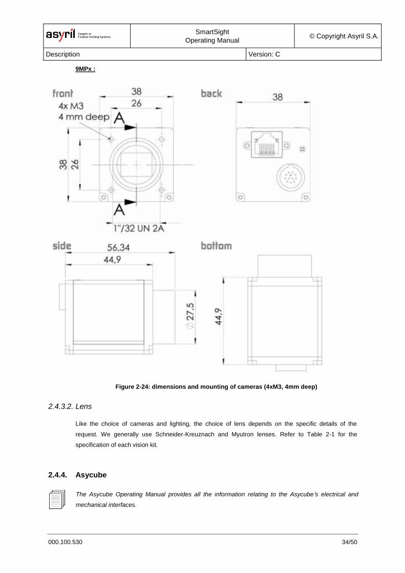
2.4.3.1. Camera
All the cameras which can be connected to the Asyview are SVS-Vistek cameras. Their dimensions and
mounting components are illustrated in Figure 2-24.
1.4MPx + 5MPx :
The frontlight (a doal in this example) can be positioned
freely at 4x90°
SmartSight
Operating Manual © Copyright Asyril S.A.
Description Version: C
000.100.530 34/50
9MPx :
Figure 2-24: dimensions and mounting of cameras (4xM3, 4mm deep)
2.4.3.2. Lens
Like the choice of cameras and lighting, the choice of lens depends on the specific details of the
request. We generally use Schneider-Kreuznach and Myutron lenses. Refer to Table 2-1 for the
specification of each vision kit.
2.4.4. Asycube
The Asycube Operating Manual provides all the information relating to the Asycube’s electrical and
mechanical interfaces.
SmartSight
Operating Manual © Copyright Asyril S.A.
Description Version: C
000.100.530 35/50
2.5. Accessories and optional modules
These components are defined by Asyril according to customer requirements. CAD model can also be
downloaded on the Asyril webpage. The key information on the choice of equipment is provided below.
2.5.1. Lighting
We mainly work with Effilux lighting systems. In addition to using the specific type and size of lighting for
your requirements, the lighting supply must be 24 VDC (max. 3.5A), it is supplied and switched through
the EasyConnectBox.
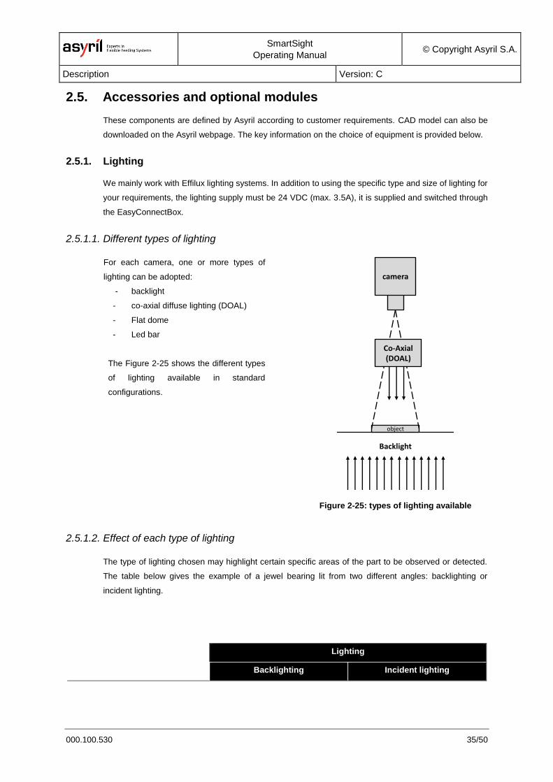
2.5.1.1. Different types of lighting
For each camera, one or more types of
lighting can be adopted:
- backlight
- co-axial diffuse lighting (DOAL)
- Flat dome
- Led bar
The Figure 2-25 shows the different types
of lighting available in standard
configurations.
Figure 2-25: types of lighting available
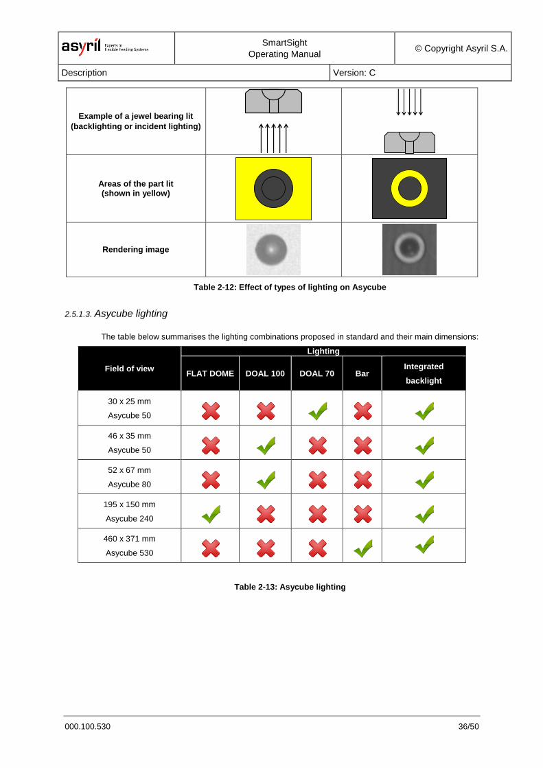
2.5.1.2. Effect of each type of lighting
The type of lighting chosen may highlight certain specific areas of the part to be observed or detected.
The table below gives the example of a jewel bearing lit from two different angles: backlighting or
incident lighting.
Lighting
Backlighting Incident lighting
object
camera
Backlight
Dark fieldDark field
Co-Axial(DOAL)
SmartSight
Operating Manual © Copyright Asyril S.A.
Description Version: C
000.100.530 36/50
Example of a jewel bearing lit
(backlighting or incident lighting)
Areas of the part lit (shown in yellow)
Rendering image
Table 2-12: Effect of types of lighting on Asycube
2.5.1.3. Asycube lighting
The table below summarises the lighting combinations proposed in standard and their main dimensions:
Field of view
Lighting
FLAT DOME DOAL 100 DOAL 70 Bar Integrated
backlight
30 x 25 mm
Asycube 50
46 x 35 mm
Asycube 50
52 x 67 mm
Asycube 80
195 x 150 mm
Asycube 240
460 x 371 mm
Asycube 530
Table 2-13: Asycube lighting
SmartSight
Operating Manual © Copyright Asyril S.A.
Description Version: C
000.100.530 37/50
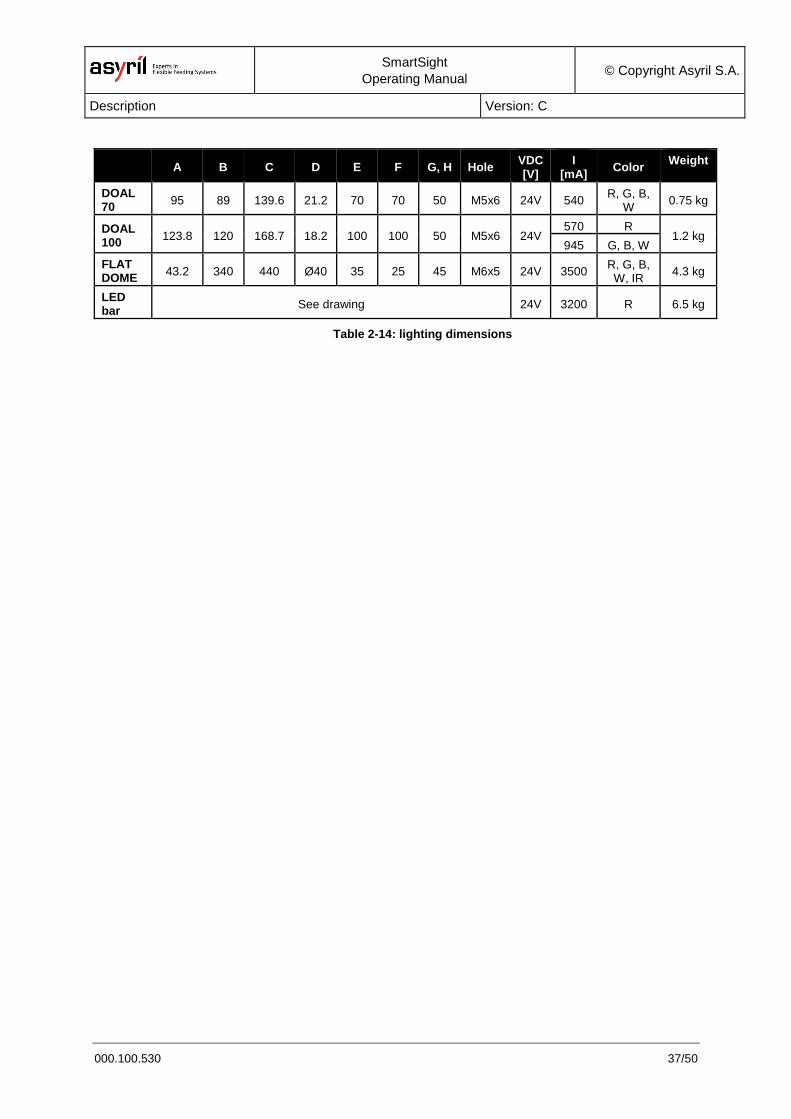
A B C D E F G, H Hole VDC [V]
I [mA]
Color Weight
DOAL 70
95 89 139.6 21.2 70 70 50 M5x6 24V 540 R, G, B,
W 0.75 kg
DOAL 100
123.8 120 168.7 18.2 100 100 50 M5x6 24V 570 R
1.2 kg 945 G, B, W
FLAT DOME
43.2 340 440 Ø40 35 25 45 M6x5 24V 3500 R, G, B, W, IR
4.3 kg
LED bar
See drawing 24V 3200 R 6.5 kg
Table 2-14: lighting dimensions
SmartSight
Operating Manual © Copyright Asyril S.A.
Description Version: C
000.100.530 38/50
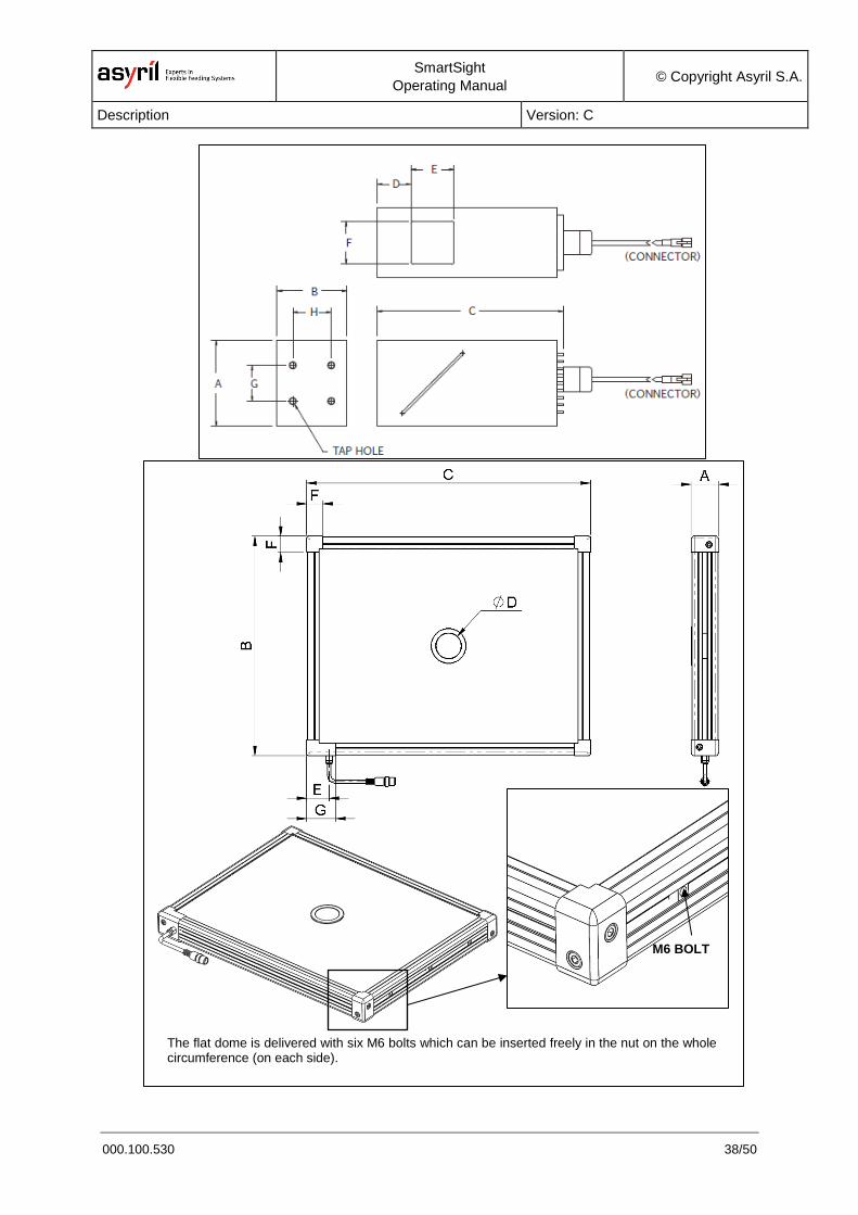
M6 BOLT
The flat dome is delivered with six M6 bolts which can be inserted freely in the nut on the whole circumference (on each side).
SmartSight
Operating Manual © Copyright Asyril S.A.
Description Version: C
000.100.530 39/50
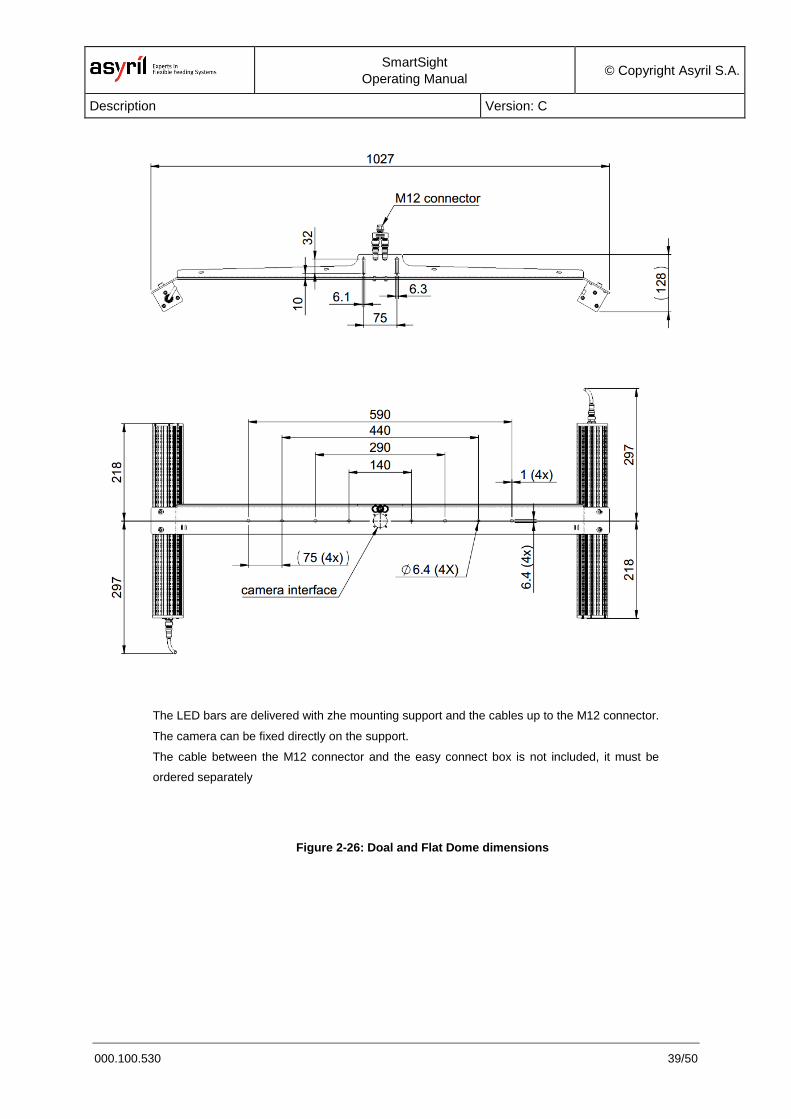
Figure 2-26: Doal and Flat Dome dimensions
The LED bars are delivered with zhe mounting support and the cables up to the M12 connector.
The camera can be fixed directly on the support.
The cable between the M12 connector and the easy connect box is not included, it must be
ordered separately
SmartSight
Operating Manual © Copyright Asyril S.A.
Description Version: C
000.100.530 40/50
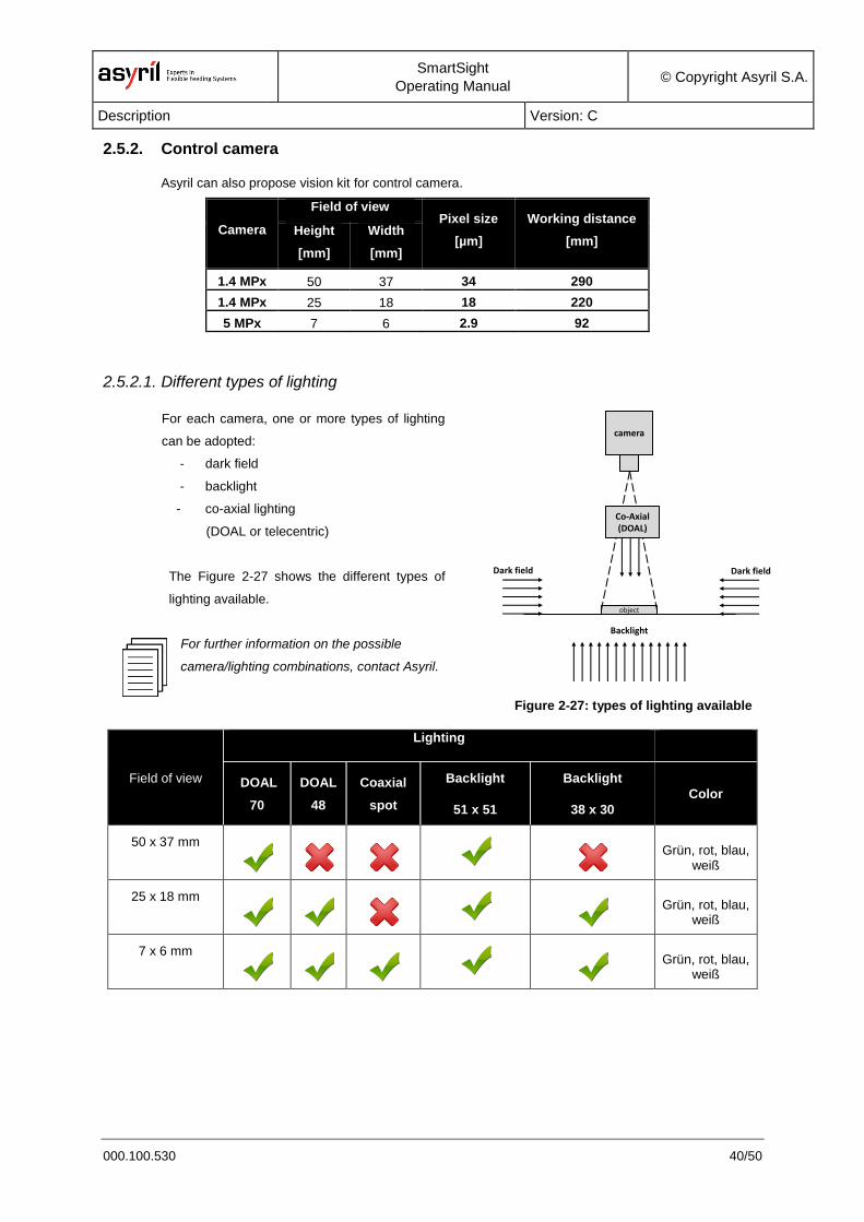
2.5.2. Control camera
Asyril can also propose vision kit for control camera.
Camera
Field of view Pixel size
[µm]
Working distance
[mm] Height
[mm]
Width
[mm]
1.4 MPx 50 37 34 290
1.4 MPx 25 18 18 220
5 MPx 7 6 2.9 92
2.5.2.1. Different types of lighting
For each camera, one or more types of lighting
can be adopted:
- dark field
- backlight
- co-axial lighting
(DOAL or telecentric)
The Figure 2-27 shows the different types of
lighting available.
For further information on the possible
camera/lighting combinations, contact Asyril.
Figure 2-27: types of lighting available
Field of view
Lighting
DOAL
70
DOAL
48
Coaxial
spot
Backlight
51 x 51
Backlight
38 x 30
Color
50 x 37 mm
Grün, rot, blau, weiß
25 x 18 mm
Grün, rot, blau, weiß
7 x 6 mm
Grün, rot, blau, weiß
object
camera
Backlight
Dark fieldDark field
Co-Axial(DOAL)
SmartSight
Operating Manual © Copyright Asyril S.A.
Description Version: C
000.100.530 41/50
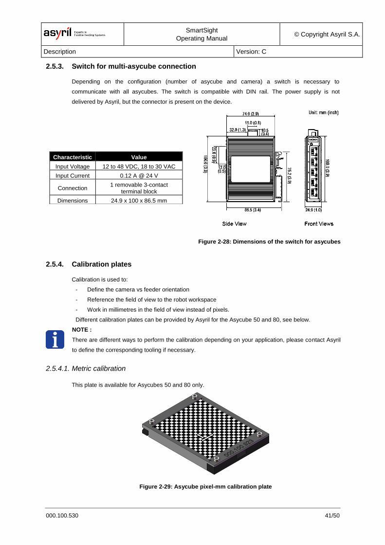
2.5.3. Switch for multi-asycube connection
Depending on the configuration (number of asycube and camera) a switch is necessary to
communicate with all asycubes. The switch is compatible with DIN rail. The power supply is not
delivered by Asyril, but the connector is present on the device.
Characteristic Value
Input Voltage 12 to 48 VDC, 18 to 30 VAC
Input Current 0.12 A @ 24 V
Connection 1 removable 3-contact
terminal block
Dimensions 24.9 x 100 x 86.5 mm
Figure 2-28: Dimensions of the switch for asycubes
2.5.4. Calibration plates
Calibration is used to:
- Define the camera vs feeder orientation
- Reference the field of view to the robot workspace
- Work in millimetres in the field of view instead of pixels.
Different calibration plates can be provided by Asyril for the Asycube 50 and 80, see below.
NOTE :
There are different ways to perform the calibration depending on your application, please contact Asyril
to define the corresponding tooling if necessary.
2.5.4.1. Metric calibration
This plate is available for Asycubes 50 and 80 only.
Figure 2-29: Asycube pixel-mm calibration plate
SmartSight
Operating Manual © Copyright Asyril S.A.
Description Version: C
000.100.530 42/50
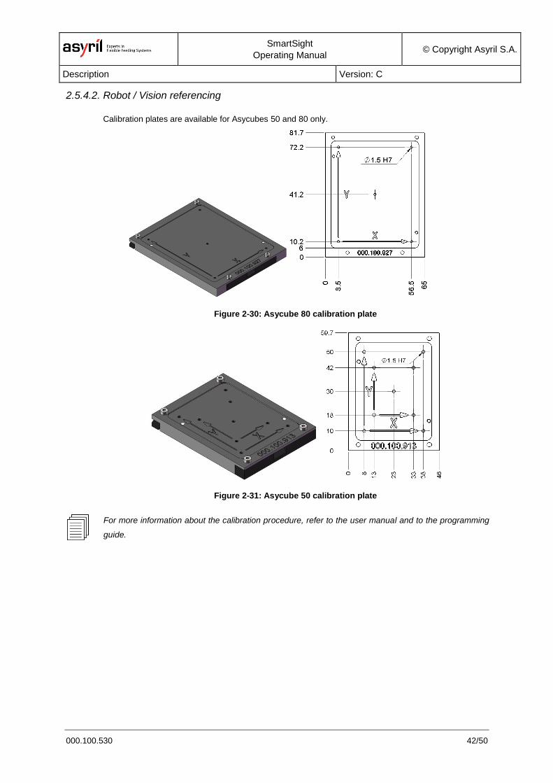
2.5.4.2. Robot / Vision referencing
Calibration plates are available for Asycubes 50 and 80 only.
Figure 2-30: Asycube 80 calibration plate
Figure 2-31: Asycube 50 calibration plate
For more information about the calibration procedure, refer to the user manual and to the programming
guide.
SmartSight
Operating Manual © Copyright Asyril S.A.
Transportation, handling and installation Version: C
000.100.530 43/50
3. Transportation, handling and installation
3.1. Product packaging, transportation and handling
The product must be transported in accordance with the specifications indicated on the package (top,
bottom, fragile, etc.). In addition, the following points must be strictly respected:
IMPORTANT!
- Take adequate precautions during handling.
- Do not climb on the package.
- Never place heavy objects on the package.
- Take particular care to avoid damaging the product during transportation.
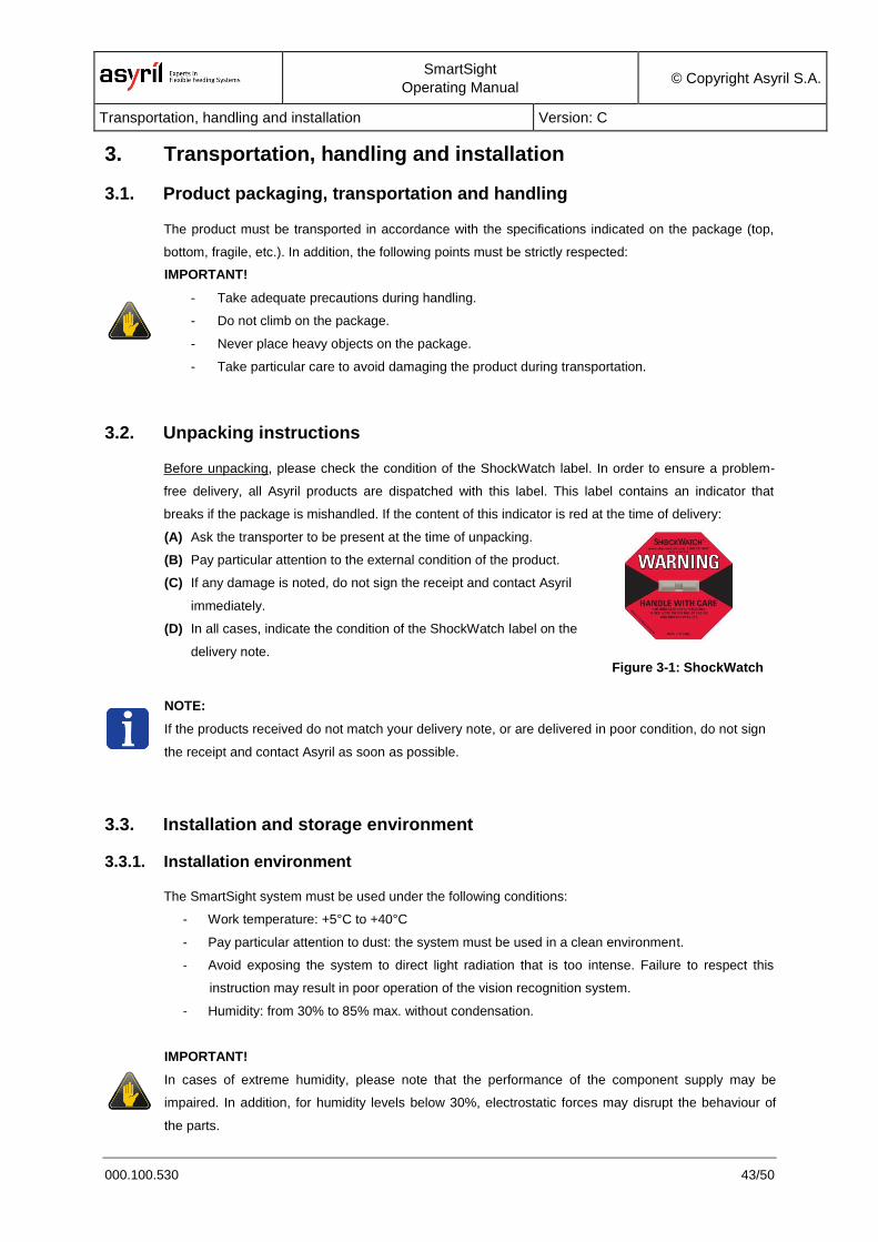
3.2. Unpacking instructions
Before unpacking, please check the condition of the ShockWatch label. In order to ensure a problem-
free delivery, all Asyril products are dispatched with this label. This label contains an indicator that
breaks if the package is mishandled. If the content of this indicator is red at the time of delivery:
(A) Ask the transporter to be present at the time of unpacking.
(B) Pay particular attention to the external condition of the product.
(C) If any damage is noted, do not sign the receipt and contact Asyril
immediately.
(D) In all cases, indicate the condition of the ShockWatch label on the
delivery note.
Figure 3-1: ShockWatch
NOTE:
If the products received do not match your delivery note, or are delivered in poor condition, do not sign
the receipt and contact Asyril as soon as possible.
3.3. Installation and storage environment
3.3.1. Installation environment
The SmartSight system must be used under the following conditions:
- Work temperature: +5°C to +40°C
- Pay particular attention to dust: the system must be used in a clean environment.
- Avoid exposing the system to direct light radiation that is too intense. Failure to respect this
instruction may result in poor operation of the vision recognition system.
- Humidity: from 30% to 85% max. without condensation.
IMPORTANT!
In cases of extreme humidity, please note that the performance of the component supply may be
impaired. In addition, for humidity levels below 30%, electrostatic forces may disrupt the behaviour of
the parts.
SmartSight
Operating Manual © Copyright Asyril S.A.
Transportation, handling and installation Version: C
000.100.530 44/50
- Avoid powerful electromagnetic waves, ultraviolet light or other radiation.
- Do not use the product in an area where it may be exposed to water or oil projections.
- ISO7 type cleanroom applications
IMPORTANT!
The product must not be used in a corrosive gas atmosphere. Oxidation may occur, resulting in damage
to the product.
3.3.2. Storage environment
The storage environment of the product must be similar to its operating environment.
SmartSight
Operating Manual © Copyright Asyril S.A.
Maintenance and repair Version: C
000.100.530 45/50
4. Maintenance and repair
4.1. Safety instructions
4.1.1. General instructions
IMPORTANT!
No maintenance operation must be performed inside the product. To perform internal maintenance
operations, please contact Asyril. Failure to respect this requirement will invalidate the warranty.
DANGER!
Never use the system when it is damaged. Check that you have resolved the problem before
restarting the machine.
DANGER!
Stop the system and disconnect it from its supply before carrying out any maintenance
operation.
DANGER!
Never pour water over the product. Spraying water over the product or cleaning it with water
may cause serious malfunctions, or cause injuries due to the associated electrical danger.
4.2. Personnel responsible for maintenance or repair operations
Maintenance operations must be performed by trained personnel. Three categories of personnel are
defined:
(A) Maintenance technicians who have not been trained by Asyril
(B) Maintenance technicians who have been trained by Asyril
(C) Asyril maintenance technicians.
Ensure that the person responsible for the maintenance work performed on the product has read and
understood this manual. In all cases, the safety precautions must imperatively be followed.
NOTE:
A report will be written for each maintenance operation performed by Asyril.
For more information about our maintenance service, please consult our After-Sales department.
SmartSight
Operating Manual © Copyright Asyril S.A.
Maintenance and repair Version: C
000.100.530 46/50
4.3. Maintenance
NOTE:
The information given in the table below is provided purely for illustrative purposes. The frequency at
which these operations should be performed must be adapted according to usage of the product, the
operating environment, etc.
4.3.1. Maintenance schedule
The SmartSight system and its accessories require little maintenance, however, simple inspections
must be performed at regular intervals in order to ensure optimal performance of the product:
Operation Period Personnel Reference
Optical parts Visually inspect and, if necessary, clean Monthly A -
Control unit Saving recipes Monthly A Refer to the HMI doc.
Control unit System backup/restore Yearly B
HowTo documentation delivered after training by
Asyril
Table 4-1: Periodic maintenance table
IMPORTANT!
Regardless of the type of maintenance operation, always use genuine Asyril parts.
NOTE:
For Asycube maintenance information, see the Asycube user documentation.
4.3.2. General maintenance
4.3.2.1. Cleaning the optical parts
Visually inspect the optical parts (camera, lens, lighting, etc.) and clean if necessary.

SmartSight
Operating Manual © Copyright Asyril S.A.
Maintenance and repair Version: C
000.100.530 47/50
4.4. Repairs
This section provides a non-exhaustive list of the available spare parts for your product. The product
should be returned to the manufacturer for any repair work. In exceptional cases, and after approval by
Asyril SA, this repair work may be performed in the client's premises by trained personnel.
IMPORTANT!
Regardless of the type of replacement operation, always use genuine Asyril parts.
Two types of parts are defined:
(A) Parts likely to be replaced every year (wearing parts)
(B) Parts likely to be replaced every 5 years.
Description of part Type Item number
PC VECOW ECS-9210 I5 B according to order confirmation
CAMERA B according to order confirmation
LIGHTING B according to order confirmation
SWITCH B according to order confirmation
Table 4-2: SmartSight spare parts
NOTE:
For Asycube spare parts, see the Asycube operating manual documentation.
SmartSight
Operating Manual © Copyright Asyril S.A.
Maintenance and repair Version: C
000.100.530 48/50
4.5. Technical Support
4.5.1. For a better service …
Before contacting asyril, please note down the following information concerning your product:
Serial number and product key for your equipment
Software version(s) used
Error message, alarm, or visual signals displayed by the interface.
4.5.2. Contact
You can find extensive information on our website: www.asyril.com
You can also contact our Customer Service department:
http://www.asyril.com/en/asyril/support-en.html
SmartSight
Operating Manual © Copyright Asyril S.A.
Revision table Version: C
000.100.530 49/50
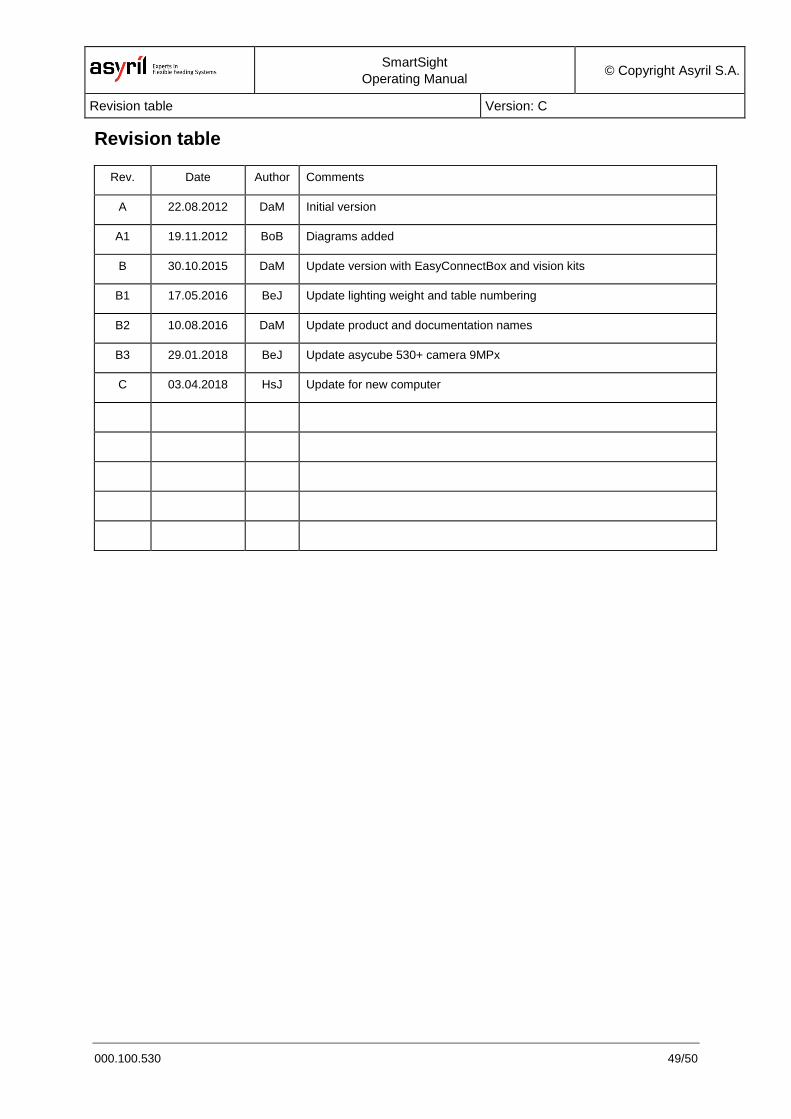
Revision table
Rev. Date Author Comments
A 22.08.2012 DaM Initial version
A1 19.11.2012 BoB Diagrams added
B 30.10.2015 DaM Update version with EasyConnectBox and vision kits
B1 17.05.2016 BeJ Update lighting weight and table numbering
B2 10.08.2016 DaM Update product and documentation names
B3 29.01.2018 BeJ Update asycube 530+ camera 9MPx
C 03.04.2018 HsJ Update for new computer
SmartSight
Operating Manual © Copyright Asyril S.A.
Revision table Version: C
000.100.530 50/50
This document is the property of Asyril S.A.; it may not be reproduced, modified or communicated, in whole or in
part, without our prior written authorisation. Asyril S.A. reserves the right to modify any information contained in
this document for reasons related to product improvements without prior notice.
Asyril SA
Z.I. le Vivier 22
Ch-1690 Villaz-St-Pierre
Switzerland
Tel. +41 26 653 71 90
Fax +41 26 653 71 91
www.asyril.com