Embed Size (px)
Citation preview
TM 10-8470-208-10
TECHNICAL MANUAL
OPERATOR MANUAL
FOR
IMPROVED OUTER TACTICAL VEST (IOTV)
AND
IMPROVED OUTER TACTICAL VEST GEN II (IOTV GEN II)
PART OF THE
INTERCEPTOR BODY ARMOR SYSTEM
DISTRIBUTION STATEMENT A – Approved for public release; distribution is unlimited.
HEADQUARTERS, DEPARTMENT OF THE ARMY
01 MARCH 2010

TM 10-8470-208-10
a
WARNING SUMMARY
This warning summary contains general safety warnings and hazardous materials warnings that must be understood and applied during operation and maintenance of this equipment. Failure to observe these precautions could result in serious injury or death to personnel. Also included are explanations of safety and hazardous material icons used within the technical manual. FIRST AID DATA For first aid information, refer to FM 4-25.11. WARNING DESCRIPTIONS
WARNING
Ensure the sizes of the front and back carrier match by comparing data plate information. Ensure the sizes of the attachable items match the sizes of the front and back carriers by comparing data plate information. Failure to do so could affect performance, causing injury or death to the servicemember.
WARNING
Ensure there are no kinks in the quick-release cable. Failure to do so could adversely affect the function of the quick-release, causing injury or death to the service member.
WARNING Pressing, starching, dry cleaning, or the use of fabric softener will degrade the IBA. Failure to following these instructions could result in harm to the soldier.
WARNING (IOTV ONLY) Ensure the quick-release cable is routed through the two grommets of the cable stop, or a malfunction may occur. It does not matter which cable is routed through which grommet.
WARNING Proper routing of the cable release assembly is critical to the proper operation of the vest during an emergency doffing. The left-hand side plate carrier (left side plate carrier for IOTV or left-hand universal side plate carrier for IOTV Gen II) should be attached first, followed by the right. Failure to follow these directions could result in injury or death.
TM 10-8470-208-10
b
WARNING DESCRIPTIONS – CONTINUED
WARNING
Do not include the flap of the back yoke when attaching the deltoid protector to the vest. Doing so may prevent the cable release from operating correctly.
WARNING During pre-combat inspections, check that side plate strap has an additional turn with the strap through the buckle for added security. Without the strap being properly secured, the plate could fall out, leaving the servicemember vulnerable to small-arms fire or fragmentation.
WARNING Ensure front and back carrier soft ballistic protection overlaps under the arm when donning the vest.
WARNING The emergency release system should be used during emergencies or instructional purposes only. Using the cable release method to routinely doff the vest could result in damage to the hard armor plates. Damage to the hard armor plates could result in injury or death to the wearer.
WARNING Do not machine wash or dry. Failure to follow these instructions may render your IBA useless against ballistic threats.
WARNING Do not machine wash or dry the ESAPI/ESBI inserts. Failure to follow these instructions may degrade the ESAPI/ESBI ballistic protection.
WARNING Service members must ensure they have the correct protective inserts. The ESAPI and ESBI have green covers and provide a higher level of protection than the Small Arms Protective Insert (SAPI) which has a black cover. ESAPI should be worn by all personnel in-theater. If a service member has the older black SAPI plates, they should be turned in and replaced with green ESAPI plates. Failure to ensure the correct plate while conducting combat operations may result in injury or death.
TM 10-8470-208-10
c/d blank
WARNING DESCRIPTIONS – CONTINUED
WARNING
Fabric repair in this work package does not apply to the fabric on the soft ballistic inserts. Any damage to the soft ballistic inserts is cause for turn in. Failure to follow these instructions could result in degraded ballistic protection.
END OF WORK PACKAGE

TM 10-8470-208-10
A/B blank
LIST OF EFFECTIVE PAGES/WORK PACKAGES NOTE: Zero in the “Change No.” column indicates an original page or work package.
Date of issue for the original manual is: Original 01 March 2010
TOTAL NUMBER OF PAGES FOR FRONT AND REAR MATTER IS 26 AND TOTAL NUMBER OF WORK PACKAGES IS 162, CONSISTING OF THE FOLLOWING:
Page / WP No. Change
No.
Title (2 pgs) 0 Warning (4 pgs) 0 i-viii (8 pgs) 0 Ch 1 title page (2 pgs) 0 WP 0001 (4 pgs) 0 WP 0002 (18 pgs) 0 WP 0003 (2 pgs) 0 Ch 2 title page (2 pgs) 0 WP 0004 (26 pgs) 0 WP 0005 (8 pgs) 0 WP 0006 (2 pgs) 0 Ch 3 title page (2 pgs) 0 WP 0007 (2 pgs) 0 WP 0008 (50 pgs) 0 Ch 4 title page (2 pgs) 0 WP 0009 (2 pgs) 0 WP 0010 (4 pgs) 0 WP 0011 (2 pgs) 0 WP 0012 (2 pgs) 0 Ch 5 title page (2 pgs) 0 WP 0013 (2 pgs) 0 WP 0014 (26 pgs) 0 WP 0015 (2 pgs) 0

TM 10-8470-208-10
i
HEADQUARTERS DEPARTMENT OF THE ARMY
WASHINGTON, D.C., 01 March 2010
TECHNICAL MANUAL
OPERATOR MANUAL
FOR IMPROVED OUTER TACTICAL VEST (IOTV)
AND
IMPROVED OUTER TACTICAL VEST GEN II (IOTV GEN II)
A PART OF THE
INTERCEPTOR BODY ARMOR SYSTEM
REPORTING ERRORS AND RECOMMENDING IMPROVEMENTS
You can help improve this manual. If you find any mistakes or if you know of a way to improve the procedures, please let us know. Mail your letter or DA Form 2028 (Recommended Changes to Publications and Blank Forms) directly to: Commander, TACOM Life Cycle Management Command, ATTN: AMSTA-LCL-MPP/TECH PUBS, 1 Rock Island Arsenal, Rock Island, IL 61299-7630. You may also send in your recommended changes via electronic mail or by fax. Our fax is DSN 793-0726, and Commercial 309-782-0726. Our e-mail address is [email protected]. A reply will be furnished to you.
DISTRIBUTION STATEMENT A: Approved for public release; distribution is unlimited.
TM 10-8470-208-10
ii
TABLE OF CONTENTS WP Sequence No.
Page No.
Warning Summary a
How to Use This Manual vi
Chapter 1 – General Information, Equipment Description, and Theory of Operation for Improved Outer Tactical Vest (IOTV) and Improved Outer Tactical Vest Gen II (IOTV Gen II)
General Information ...................................................................................... WP 0001
Table 1. Nomenclature Cross Reference List ................................ 0001-2
Table 2. List of Abbreviations/Acronyms ........................................ 0001-3
Equipment Description and Data .................................................................. WP 0002
Figure 1. Front Carrier (IOTV Shown). ........................................... 0002-3
Figure 2. Back Carrier (IOTV Shown). ........................................... 0002-5
Figure 3. Back Carrier Cable Routing ............................................ 0002-6
Figure 4. Side Plate Carriers (IOTV) ............................................... 0002-7
Figure 5. Internal Elastic Bands ...................................................... 0002-8
Figure 6. Cable Release Assembly ................................................ 0002-8
Figure 7. Yoke/Collar Assembly ..................................................... 0002-9
Figure 8. Deltoid and Groin Protectors ......................................... 0002-10
Figure 9. Lower Back Protector. ................................................... 0002-11
Figure 10. ESBI and ESAPI Plates............................................... 0002-12
Figure 11. Differences between IOTV and IOTV Gen II Front Carriers ....................................................................................... 0002-13
Table 1. IOTV System Weight Chart (in pounds). ......................... 0002-16
Table 2. IOTV Gen II System Weight Chart (in pounds).. ............. 0002-17
Theory of Operation ..................................................................................... WP 0003
Chapter 2 – Operator Instructions for Improved Outer Tactical Vest (IOTV) and Improved Outer Tactical Vest Gen II (IOTV Gen II)
Operation Under Usual Conditions – Assembly ........................................... WP 0004
Table 1. IOTV and IOTV Gen II Inventory ...................................... 0004-2
Table 2. IOTV and IOTV Gen II Component Sizing Chart .............. 0004-6
TM 10-8470-208-10
TABLE OF CONTENTS – CONTINUED WP Sequence No.
Page No.
iii
Figure 1. Placing Carrier Exterior Fabric Down ............................... 0004-7
Figure 2. Inserting Soft Ballistics. .................................................... 0004-8
Figure 3. Inserting Soft Ballistics ..................................................... 0004-9
Figure 4. Inserting Soft Ballistics into Lower Back Protector ......... 0004-10
Figure 5. Opening Hard Armor Protective Insert Pocket. .............. 0004-11
Figure 6. Inserting Hard Armor Protective Insert ........................... 0004-11
Figure 7. Re-sealing the Hard Armor Ballistic Insert Pocket ......... 0004-12
Figure 8. Attaching Front Collar. .................................................... 0004-13
Figure 9. Attaching Back Collar. .................................................... 0004-14
Figure 10. Routing Cable through Cable Stop. ............................. 0004-14
Figure 11. Routing the Cable Release Assembly on Front Carrier. ...................................................................................... 0004-15
Figure 12. Adjusting Left Shoulder Webbing Length. ................... 0004-16
Figure 13. Connecting Front and Back Carriers ............................ 0004-17
Figure 14. Routing Short Release Cable ....................................... 0004-18
Figure 15. Routing Long Release Cable though the Lower Access Panel ............................................................................ 0004-18
Figure 16. Installing the Internal Elastic Bands ............................. 0004-19
Figure 17. Installing the Side Plate Carriers .................................. 0004-20
Figure 18. Routing Cable Release through Side Plate Carriers .... 0004-22
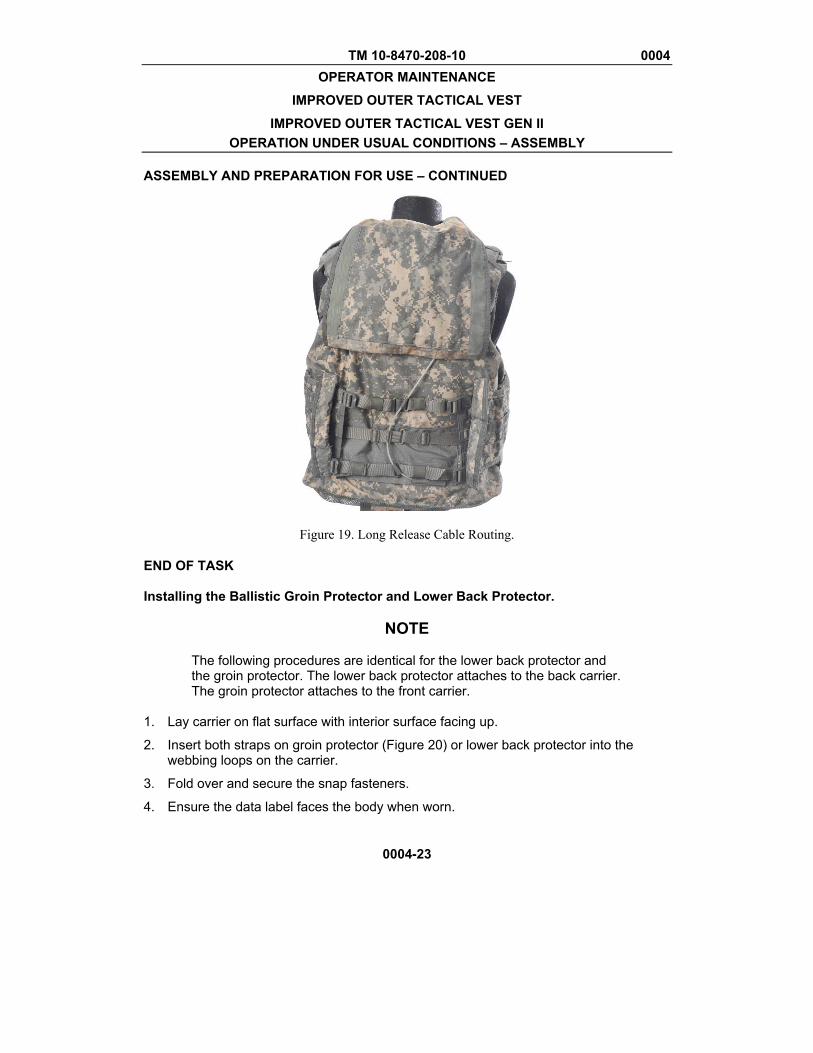
Figure 19. Long Release Cable Routing ....................................... 0004-23
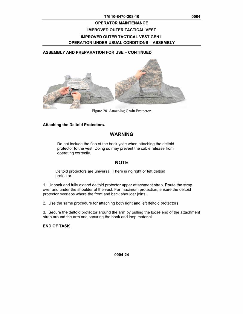
Figure 20. Attaching Groin Protector ............................................. 0004-24
Operation Under Usual Conditions – Don, Doff, Adjust ............................... WP 0005
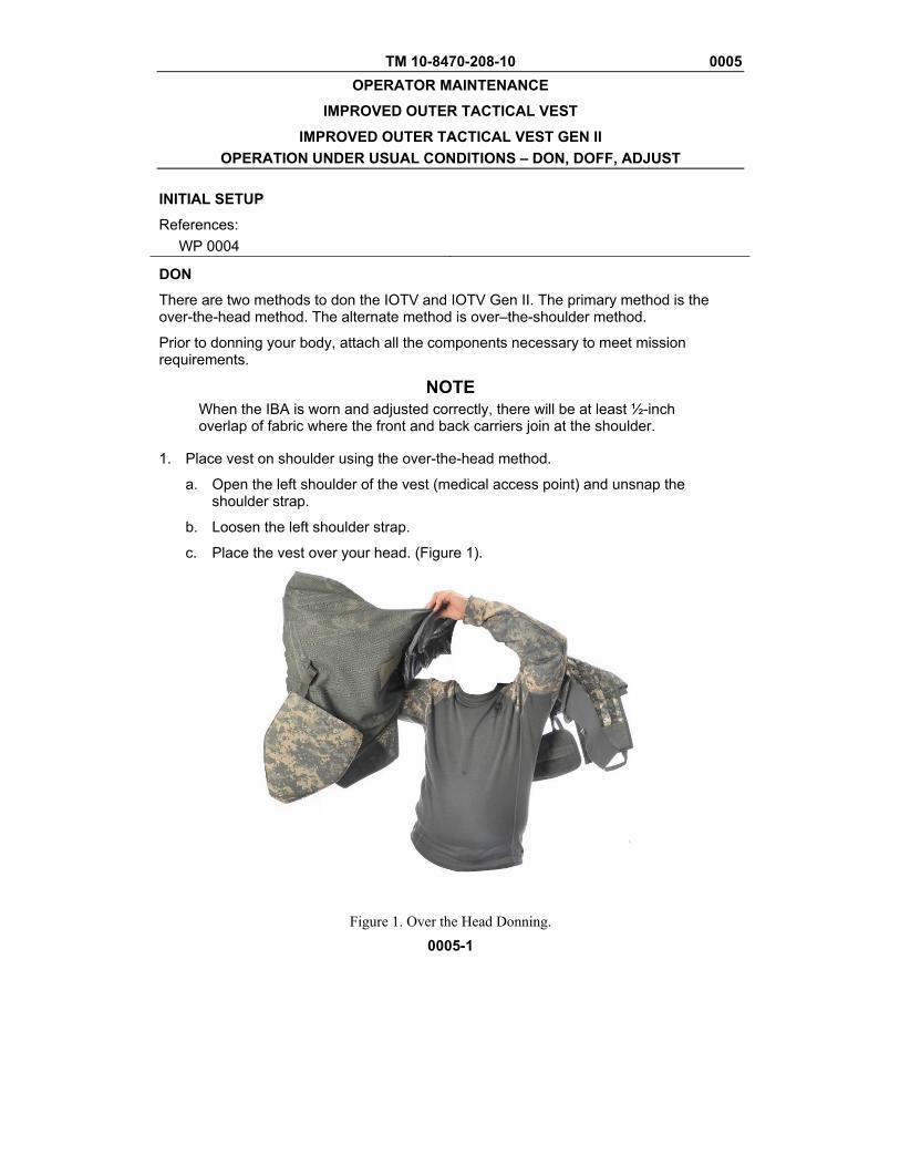
Figure 1. Over the Head Donning .................................................... 0005-1
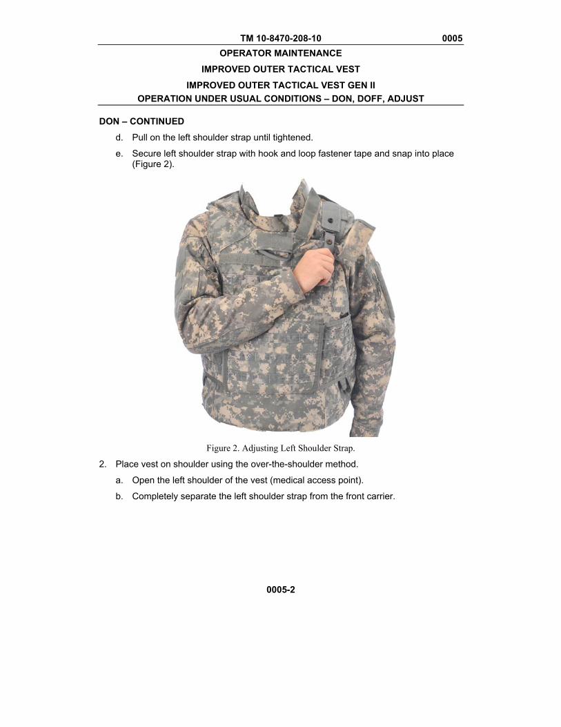
Figure 2. Adjusting Left Shoulder Strap. ......................................... 0005-2
Figure 3. Donning Over-the-Shoulder ............................................. 0005-3
Figure 4. Securing Left Shoulder Strap ........................................... 0005-4
Figure 5. Securing Side Plate Carriers ............................................ 0005-5
Figure 6. Aligning Side Plate Carrier Attachment Points ................. 0005-7
Figure 7. Adjusting Side Plate Carrier and Internal Elastic Band Straps .......................................................................................... 0005-8
TM 10-8470-208-10
TABLE OF CONTENTS – CONTINUED WP Sequence No.
Page No.
iv
Operation Under Unusual Conditions .......................................................... WP 0006
Chapter 3 – Preventive Maintenance Checks and Services for Improved Outer Tactical Vest (IOTV) and Improved Outer Tactical Vest Gen II (IOTV Gen II)
Preventive Maintenance Checks and Services (PMCS) Introduction .......... WP 0007
Preventive Maintenance Checks and Services (PMCS) .............................. WP 0008
Table 1. Preventive Maintenance Checks and Services ................ 0008-2
Figure 1. Smoothing out IOTV ........................................................ 0008-4
Figure 2. Inspect Plates .................................................................. 0008-5
Figure 3. Donning IOTV (Over-the-Head Method) ......................... 0008-7
Figure 4. Securing Internal Elastic Bands ...................................... 0008-9
Figure 5. Securing Side Plate Carriers .........................................0008-10
Figure 6. Correct Side Ballistic Protection ....................................0008-11
Figure 7. Routing Check ................................................................0008-12
Figure 8. Check for Bridging .........................................................0008-13
Figure 9. Webbing Properly Stowed ............................................. 0008-15
Figure 10. Back Cable Routing ..................................................... 0008-16
Figure 11. Removing ESAPI Plates.............................................. 0008-19
Figure 12. Removing ESBI Plates ................................................ 0008-19
Figure 13. Removing Soft Ballistic Inserts .................................... 0008-20
Figure 14. Removing Yoke/Collar Assembly ................................ 0008-21
Figure 15. IOTV Inventory ............................................................ 0008-23
Figure 16. IOTV Gen II Inventory ................................................. 0008-24
Figure 17. Cleaning IOTV ............................................................. 0008-25
Figure 18. Cleaning Restrictions .................................................. 0008-26
Figure 19. Installing Soft Ballistic Inserts ...................................... 0008-29
Figure 20. Installing Cable Release on Front Carrier ................... 0008-31
Figure 21. Connecting Front and Back Carriers ........................... 0008-33
Figure 22. Routing Strap Loops into Front Carrier Shoulder
Buckles ..................................................................................0008-34

TM 10-8470-208-10
TABLE OF CONTENTS – CONTINUED WP Sequence No.
Page No.
v
Figure 23. Routing Cable Release (Upper Panel) ........................ 0008-35
Figure 24. IOTV Cable Routing, Lower Panel .............................. 0008-38
Figure 25. Attaching Yoke/Collar Assembly ................................. 0008-40
Figure 26. Attaching Groin and Lower Back Protectors ............... 0008-42
Figure 27. Installing Deltoid Protectors ........................................ 0008-44
Figure 28. Inserting ESAPI Plates ................................................ 0008-45
Figure 29. Inserting ESBI Plates .................................................. 0008-47
Figure 30. Adjusting Size .............................................................. 0008-49
Chapter 4 – Maintenance Instructions for Improved Outer Tactical Vest (IOTV) and Improved Outer Tactical Vest Gen II (IOTV Gen II)
Preparation for Storage and Shipment ......................................................... WP 0009
IOTV and IOTV Gen II Service – Cleaning and Drying ................................ WP 0010
ESAPI/ESBI Inserts –Inspect, Repair .......................................................... WP 0011
IOTV and IOTV Gen II Service – Fabric Repair ........................................... WP 0012
Figure 1. Straight Stitch .................................................................. 0012-1
Figure 2. Edge Sew ........................................................................ 0012-1
Figure 3. Turn Edge Under and Sew .............................................. 0012-2
Chapter 5 – Supporting Information for Improved Outer Tactical Vest (IOTV) and Improved Outer Tactical Vest Gen II (IOTV Gen II)
References ................................................................................................... WP 0013
Components of End Item (COEI) and Basic Issue Items (BII) Lists ............. WP 0014
Table 1. Components of End Item (COEI) – IOTV ......................... 0014-2
Table 2. Components of End Item (COEI) – IOTV Gen II ............ 0014-12
Table 3. Basic Issue Items (BII) - IOTV ........................................ 0014-21
Table 4. Basic Issue Items (BII) – IOTV Gen II ............................ 0014-25
Expendable and Durable Items List ............................................................. WP 0015
Table 1. Expendable and Durable Items List ................................ 0015-2

TM 10-8470-208-10
vi
HOW TO USE THIS MANUAL
HOW TO OBTAIN TECHNICAL MANUALS When a new system is introduced to the Army inventory, it is the responsibility of the receiving units to notify and inform the Unit Publications Clerk that a Technical Manual is available for the new system. Throughout the life cycle of the new system, the Publications Proponent will also provide updates and changes to the Technical Manual. To receive new Technical Manuals or change packages to fielded Technical Manuals, provide the Unit Publications Clerk the full Technical Manual number, title, date of publication, and number of copies required. The Unit Publications Clerk will then justify the request through the Unit Publications Officer. When the request is approved, DA Form 12-R is used to order the Technical Manual from the Army Publishing Directorate (APD). Obtain the form and request a publications account from the APD Web site at http://www.apd.army.mil. Once on the Website click on the “Orders/Subscriptions/Reports” tab. From the dropdown menu, select “Establish an Account,” then select “Tutorial” and follow the instructions in the tutorial presentation. Complete information for obtaining Army publications can be found in DA PAM 25-33. Organization of This Manual In this manual, primary chapters appear in upper case/capital letters; work packages are presented in numeric sequence, e.g., 0001, 0002; paragraphs within a work package are not numbered and are presented in a titled format. For a first level paragraph, titles are in all bold, upper case, capital letters, e.g., FRONT MATTER. Subordinate paragraph titles will have the first letter of the first word of each principle word all upper case, capital letters, all bold, e.g., Manual Organization and Page Numbering System. The location of additional material that must be referenced is clearly marked. Illustrations supporting maintenance procedures/text are located underneath, or as close as possible to, their referenced paragraph. Notes, Cautions, and Warning are located directly above the procedure to which they apply. FRONT MATTER. Front matter consists of front cover, warning summary, title block, table of contents, and how to use this manual page. CHAPTER 1 - GENERAL INFORMATION, EQUIPMENT DESCRIPTION, AND THEORY OF OPERATION. Chapter 1 contains introductory information on the Interceptor Body Armor (IBA) as well as theory of operation.
TM 10-8470-208-10
vii/viii blank
HOW TO USE THIS MANUAL – CONTINUED CHAPTER 2 - OPERATOR INSTRUCTIONS. Chapter 2 contains information on assembling, donning, doffing and operating the IBA system. CHAPTER 3 – PREVENTIVE MAINTENANCE CHECKS AND SERVICES. Chapter 3 identified preventive maintenance checks and services information. CHAPTER 4 – MAINTENANCE INSTRUCTIONS. Chapter 4 provides maintenance procedures, preparations for storage and shipment authorized at the service level. CHAPTER 5 - SUPPORTING INFORMATION. Chapter 5 contains references, Components of End Items List (COEI), Basic Issue Items List (BII), and expendable and durable items list. REAR MATTER. Rear matter consists of alphabetical index, DA Form 2028, authentication page, and back cover. Manual Organization and Page Numbering System. The manual is divided into eight major chapters that detail the topics mentioned above. Within each chapter are work packages covering a wide range of topics. Each work package is numbered sequentially starting at page 1. The work package has its own page numbering scheme and is independent of the page numbering used by other work packages. Each page of a work package has a page number of the form XXXX-YY where XXXX is the work package number (e.g. 0010 is work package 10) and YY represents the number of the page within that work package. A page number such as 0010-1/ 2 blank means that page 1 contains information but page 2 of that work package has been intentionally left blank. Finding Information. The table of contents permits the reader to find information in the manual quickly. The reader should start here first when looking for a specific topic. The table of contents lists the topics, figures, and tables contained within each chapter and the work package sequence number where it can be found. An Alphabetical Index can be found at the back of the manual; specific topics are listed with the corresponding work package number. WARNINGS, CAUTIONS, AND NOTES A warning identifies a clear danger to the person doing that procedure. A caution identifies risk of damage to the equipment. A note is used to highlight essential procedures, conditions, or statements or convey important instructional data to the user.

TM 10-8470-208-10
CHAPTER 1
GENERAL INFORMATION, EQUIPMENT DESCRIPTION, AND THEORY OF OPERATION
FOR IMPROVED OUTER TACTICAL VEST (IOTV)
AND IMPROVED OUTER TACTICAL VEST GEN II (IOTV GEN II)

TM 10-8470-208-10 0001 OPERATOR MAINTENANCE
IMPROVED OUTER TACTICAL VEST IMPROVED OUTER TACTICAL VEST GEN II
GENERAL INFORMATION
0001-1
SCOPE This technical manual provides operator instructions for the Improved Outer Tactical Vest (IOTV), IOTV Gen II, Enhanced Small Arms Protective Insert (ESAPI), Enhanced Side Ballistic Inserts (ESBI), and ancillary equipment of the Interceptor Body Armor (IBA) system. MAINTENANCE FORMS, RECORDS, AND REPORTS Department of the Army forms and procedures used for equipment maintenance will be those prescribed by (as applicable) DA PAM 750-8, The Army Maintenance Management System (TAMMS) Users Manual; DA PAM 738-751, Functional Users Manual for the Army Maintenance Management Systems - Aviation (TAMMS-A); or AR 700-138, Army Logistics Readiness and Sustainability. REPORTING EQUIPMENT IMPROVEMENT RECOMMENDATIONS (EIR) If your Improved Outer Tactical Vest or Improved Outer Tactical Vest Gen II needs improvement, let us know. Send us an EIR. You, the user, are the only one who can tell us what you don't like about your equipment. Let us know why you don't like the design or performance. If you have Internet access, the easiest and fastest way to report problems or suggestions is to go to https://aeps.ria.army.mil/aepspublic.cfm (scroll down and choose the “Submit Quality Deficiency Report” bar). The Internet form lets you choose to submit an Equipment Improvement Recommendation (EIR), a Product Quality Deficiency Report (PQDR or a Warranty Claim Action (WCA). You may also submit your information using an SF 368 (Product Quality Deficiency Report). You can send your SF 368 via e-mail, regular mail, or facsimile using the addresses/facsimile numbers specified in DA PAM 750-8, The Army Maintenance Management System (TAMMS) Users Manual. We will send you a reply. CORROSION PREVENTION AND CONTROL (CPC) Corrosion Prevention and Control (CPC) of Army materiel is a continuing concern. It is important that any corrosion problems with any items be reported so that the problem can be corrected and improvements can be made to prevent the problem in future items. Plastics, composites, and rubbers can also degrade. Degradation is caused by thermal (heat), oxidation (oxygen), solvation (solvents), or photolytic (light, typically UV) processes. The most common exposures are excessive heat or light. Damage from these processes will appear as cracking, softening, swelling, and/or breaking. SF Form 368, Product Quality Deficiency Report should be submitted to the address specified in DA PAM 750-8, The Army Maintenance Management System (TAMMS) Users Manual.
TM 10-8470-208-10 0001 OPERATOR MAINTENANCE
IMPROVED OUTER TACTICAL VEST IMPROVED OUTER TACTICAL VEST GEN II
GENERAL INFORMATION
0001-2
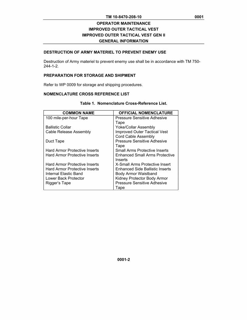
DESTRUCTION OF ARMY MATERIEL TO PREVENT ENEMY USE Destruction of Army materiel to prevent enemy use shall be in accordance with TM 750-244-1-2. PREPARATION FOR STORAGE AND SHIPMENT Refer to WP 0009 for storage and shipping procedures. NOMENCLATURE CROSS REFERENCE LIST
Table 1. Nomenclature Cross-Reference List.
COMMON NAME OFFICIAL NOMENCLATURE 100 mile-per-hour Tape Pressure Sensitive Adhesive
Tape Ballistic Collar Yoke/Collar Assembly Cable Release Assembly Improved Outer Tactical Vest
Cord Cable Assembly Duct Tape Pressure Sensitive Adhesive
Tape Hard Armor Protective Inserts Small Arms Protective Inserts Hard Armor Protective Inserts Enhanced Small Arms Protective
Inserts Hard Armor Protective Inserts X-Small Arms Protective Insert Hard Armor Protective Inserts Enhanced Side Ballistic Inserts Internal Elastic Band Body Armor Waistband Lower Back Protector Kidney Protector Body Armor Rigger’s Tape Pressure Sensitive Adhesive
Tape
TM 10-8470-208-10 0001 OPERATOR MAINTENANCE
IMPROVED OUTER TACTICAL VEST IMPROVED OUTER TACTICAL VEST GEN II
GENERAL INFORMATION
0001-3/4 blank
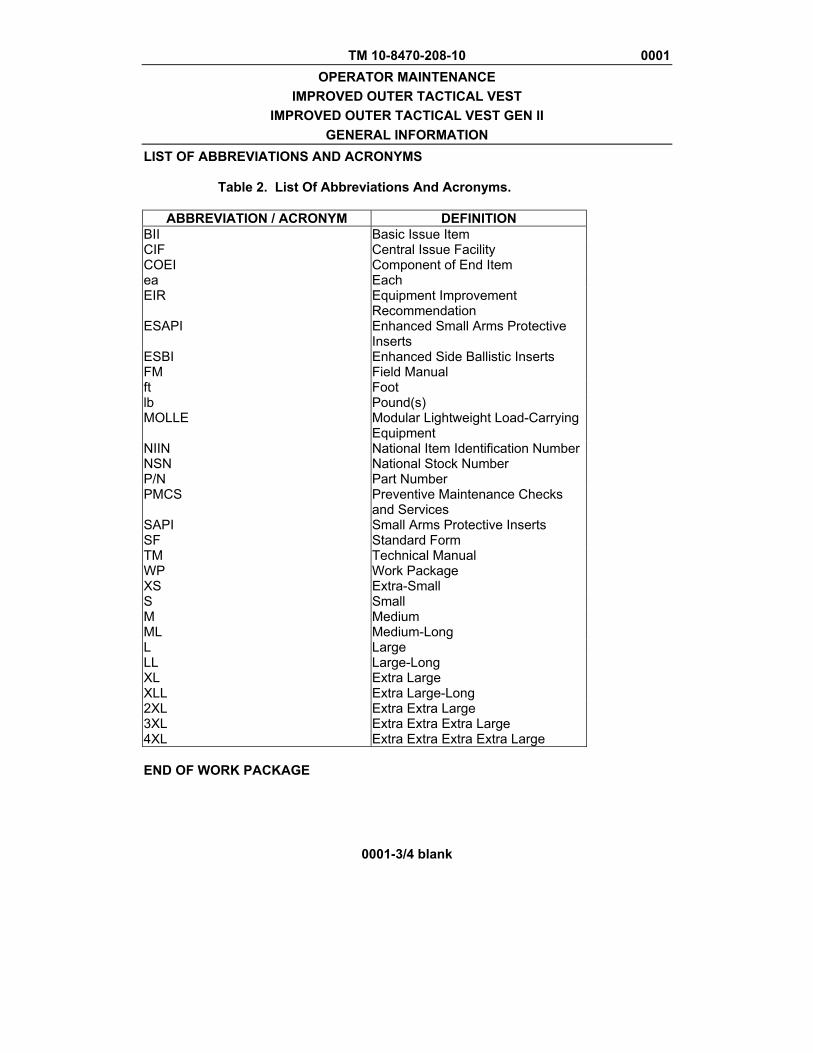
LIST OF ABBREVIATIONS AND ACRONYMS
Table 2. List Of Abbreviations And Acronyms.
ABBREVIATION / ACRONYM DEFINITION BII Basic Issue Item CIF Central Issue Facility COEI Component of End Item ea Each EIR Equipment Improvement
Recommendation ESAPI Enhanced Small Arms Protective
Inserts ESBI Enhanced Side Ballistic Inserts FM Field Manual ft Foot lb Pound(s) MOLLE Modular Lightweight Load-Carrying
Equipment NIIN National Item Identification Number NSN National Stock Number P/N Part Number PMCS Preventive Maintenance Checks
and Services SAPI Small Arms Protective Inserts SF Standard Form TM Technical Manual WP Work Package XS Extra-Small S Small M Medium ML Medium-Long L Large LL Large-Long XL Extra Large XLL Extra Large-Long 2XL Extra Extra Large 3XL Extra Extra Extra Large 4XL Extra Extra Extra Extra Large END OF WORK PACKAGE

TM 10-8470-208-10 0002 OPERATOR MAINTENANCE
IMPROVED OUTER TACTICAL VEST IMPROVED OUTER TACTICAL VEST GEN II
EQUIPMENT DESCRIPTION AND DATA
0002-1
EQUIPMENT CHARACTERISTICS, CAPABILITIES, AND FEATURES The Interceptor Body Armor (IBA) system is a modular system that consists of a vest, hard armor, and attachments (ancillary equipment) that increase area of coverage and level of protection. The IBA system is issued to Soldiers in a variety of configurations. Some vests are issued with ancillary equipment while with other vests, ancillary equipment is issued separately. Therefore, the term ancillary equipment, as used in this manual, is used to describe the attachments to the base vest configuration. Refer to the Components of End Item (COEI) list and Basic Issue Items (BII) lists for the IOTV and IOTV Gen II to determine which attachments are issued with each configuration. Vest The IBA vest comes in three basic configurations: the Outer Tactical Vest (OTV), the Improved Outer Tactical Vest (IOTV) and the Improved Outer Tactical Vest (IOTV) Gen II. This manual covers the IOTV and IOTV Gen II configurations. The IOTV and IOTV Gen II consist of a front piece and a back piece held together by a cable release assembly. The IOTV and IOTV Gen II design distributes the weight of the IBA system more evenly than previous versions of IBA. Hard Armor There are two types of hard armor, Enhanced Side Ballistic Inserts (ESBI) and Enhanced Small Arms Protective Inserts (ESAPI). The ESAPI plates provide additional levels of protection to the front and the back of the Solder. Ancillary Equipment Ancillary equipment for the IOTV and IOTV Gen II includes the yoke/collar assembly, deltoid protectors, groin protector and lower back protector. When added to the vest, these items increase the area of ballistic protection. Some items of ancillary equipment may be issued as a part of the base vest assembly, depending on the configuration. Refer to the COEI and BII for this information. Interoperability The IOTV and IOTV Gen II are compatible with Modular Lightweight Load-carrying Equipment (MOLLE) components. The IOTV and IOTV Gen II are also compatible with the Land Warrior System.

TM 10-8470-208-10 0002 OPERATOR MAINTENANCE
IMPROVED OUTER TACTICAL VEST IMPROVED OUTER TACTICAL VEST GEN II
EQUIPMENT DESCRIPTION AND DATA
0002-2
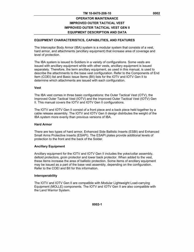
LOCATION AND DESCRIPTION OF MAJOR COMPONENTS The information in this section applies to both IOTV and IOTV Gen II systems. Features discussed are common to both configurations. Differences between models will be discussed in the next section. All graphics in this section show an IOTV but features indicated are common to both systems. Vest Front Carrier. The front carrier (Figure 1) has two shoulder straps with attached buckles. On the right shoulder is the aft guide channel used for routing of the cable release. The left shoulder has a hook and loop fastener attachment point and is referred to as the medical access point. In the center of the neckline is the location for rank placement. Behind the rank placement is a pocket for storage of the quick release handle of the cable assembly. There is also a location for the name tape placement on the right side of the chest area. MOLLE webbing is sewn on the vest for attaching items such as MOLLE pouches. There is a pull tab attached to the front flap for raising the flap. Lifting the flap exposes the hook and loop fastener tapes used to attach the side plate carriers. On the inside of the front carrier, there is webbing for attaching the ballistic groin protector. The data plate containing essential information is also located on the inside of the front carrier. Front Ballistic Insert. The front ballistic insert is located inside the front carrier and provides ballistic protection. The front ballistic insert has loop fastener tape and a data label.
TM 10-8470-208-10 0002 OPERATOR MAINTENANCE
IMPROVED OUTER TACTICAL VEST IMPROVED OUTER TACTICAL VEST GEN II
EQUIPMENT DESCRIPTION AND DATA
0002-3
LOCATION AND DESCRIPTION OF MAJOR COMPONENTS – CONTINUED
Figure 1. Front Carrier (IOTV Shown).
CABLE RELEASE ROUTING
CABLE RELEASE HANDLE POCKET
MOLLE WEBBING
FRONT FLAP
SIDE PLATE CARRIERS
YOKE AND COLLAR ASSEMBLY
MEDICAL ACCESS POINT
NAME TAPE AND RANK PATCH

TM 10-8470-208-10 0002 OPERATOR MAINTENANCE
IMPROVED OUTER TACTICAL VEST IMPROVED OUTER TACTICAL VEST GEN II
EQUIPMENT DESCRIPTION AND DATA
0002-4
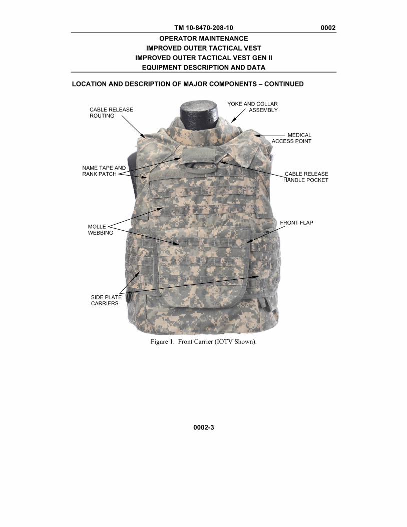
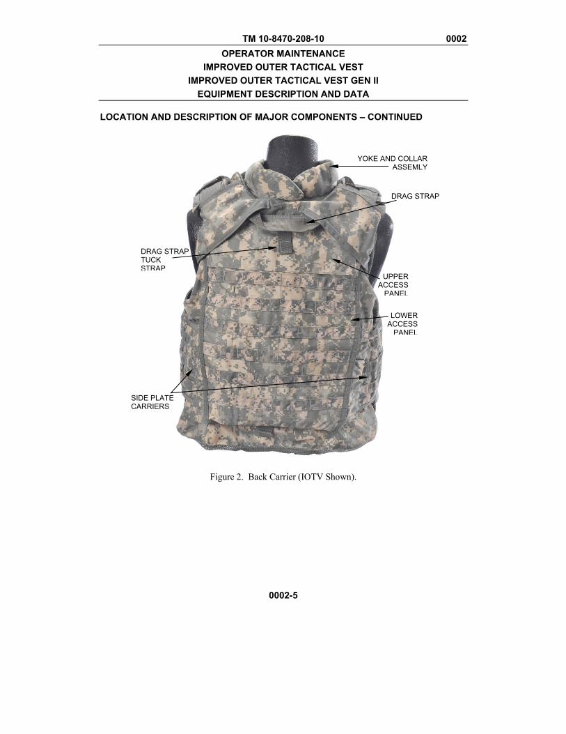
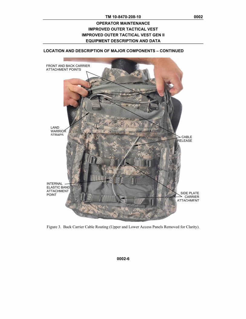
LOCATION AND DESCRIPTION OF MAJOR COMPONENTS – CONTINUED Back Carrier. On the upper portion of the Back carrier (Figure 2) are the shoulder strap guides used for routing the shoulder straps of the front carrier. There is a casualty drag strap located on the upper center portion of the carrier. There is webbing with hook and loop material for securing the strap. Keep the strap secured when not in use to prevent snagging. There are two flaps (Figure 3); a smaller upper access panel and a larger, lower access panel. The upper access panel has slits for routing the shoulder straps. In the upper compartment, there is a series of webbing used for attaching the front carrier to the back carrier. There is a right shoulder webbing loop, a center cable guide, and the left shoulder webbing loop. The two olive drab straps with an attached buckle are for use with the Land Warrior System. There is a cable retention loop located on the left side for storing the excess cable. Under the lower flap, there is additional webbing to attach the elastic internal waist band and the side plate carriers. There is a cable retaining pocket on the very bottom of the pocket for stowing excess cable. Back Ballistic Insert. The back ballistic insert is located inside the back carrier and provides ballistic protection. The back ballistic insert has loop fastener tape and a data label.
TM 10-8470-208-10 0002 OPERATOR MAINTENANCE
IMPROVED OUTER TACTICAL VEST IMPROVED OUTER TACTICAL VEST GEN II
EQUIPMENT DESCRIPTION AND DATA
0002-5
LOCATION AND DESCRIPTION OF MAJOR COMPONENTS – CONTINUED
Figure 2. Back Carrier (IOTV Shown).
YOKE AND COLLAR ASSEMLY
DRAG STRAP
UPPER ACCESS
PANEL
LOWER ACCESS
PANEL
DRAG STRAP TUCK STRAP
SIDE PLATE CARRIERS
TM 10-8470-208-10 0002 OPERATOR MAINTENANCE
IMPROVED OUTER TACTICAL VEST IMPROVED OUTER TACTICAL VEST GEN II
EQUIPMENT DESCRIPTION AND DATA
0002-6
LOCATION AND DESCRIPTION OF MAJOR COMPONENTS – CONTINUED
Figure 3. Back Carrier Cable Routing (Upper and Lower Access Panels Removed for Clarity).
CABLE RELEASE
SIDE PLATE CARRIER
ATTACHMENT
INTERNAL ELASTIC BAND ATTACHMENT POINT
LAND WARRIOR STRAPS
FRONT AND BACK CARRIER ATTACHMENT POINTS
TM 10-8470-208-10 0002 OPERATOR MAINTENANCE
IMPROVED OUTER TACTICAL VEST IMPROVED OUTER TACTICAL VEST GEN II
EQUIPMENT DESCRIPTION AND DATA
0002-7
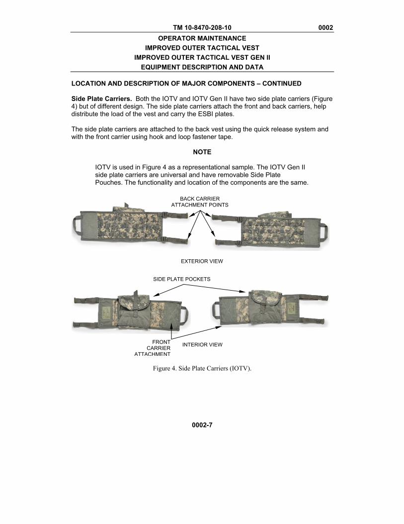
LOCATION AND DESCRIPTION OF MAJOR COMPONENTS – CONTINUED Side Plate Carriers. Both the IOTV and IOTV Gen II have two side plate carriers (Figure 4) but of different design. The side plate carriers attach the front and back carriers, help distribute the load of the vest and carry the ESBI plates. The side plate carriers are attached to the back vest using the quick release system and with the front carrier using hook and loop fastener tape.
NOTE
IOTV is used in Figure 4 as a representational sample. The IOTV Gen II side plate carriers are universal and have removable Side Plate Pouches. The functionality and location of the components are the same.
Figure 4. Side Plate Carriers (IOTV).
EXTERIOR VIEW
INTERIOR VIEW
BACK CARRIER ATTACHMENT POINTS
SIDE PLATE POCKETS
FRONT CARRIER
ATTACHMENT
TM 10-8470-208-10 0002 OPERATOR MAINTENANCE
IMPROVED OUTER TACTICAL VEST IMPROVED OUTER TACTICAL VEST GEN II
EQUIPMENT DESCRIPTION AND DATA
0002-8
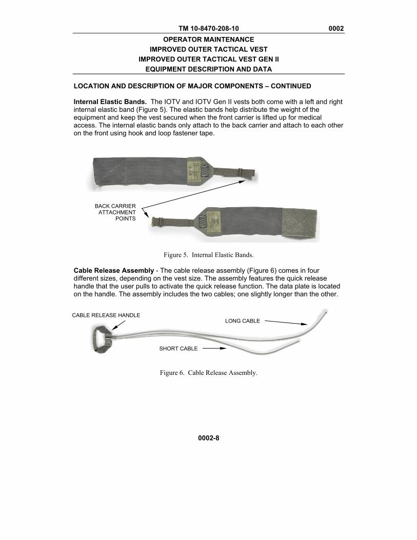
LOCATION AND DESCRIPTION OF MAJOR COMPONENTS – CONTINUED Internal Elastic Bands. The IOTV and IOTV Gen II vests both come with a left and right internal elastic band (Figure 5). The elastic bands help distribute the weight of the equipment and keep the vest secured when the front carrier is lifted up for medical access. The internal elastic bands only attach to the back carrier and attach to each other on the front using hook and loop fastener tape.
Figure 5. Internal Elastic Bands.
Cable Release Assembly - The cable release assembly (Figure 6) comes in four different sizes, depending on the vest size. The assembly features the quick release handle that the user pulls to activate the quick release function. The data plate is located on the handle. The assembly includes the two cables; one slightly longer than the other.
Figure 6. Cable Release Assembly.
BACK CARRIER ATTACHMENT
POINTS
CABLE RELEASE HANDLE
LONG CABLE
SHORT CABLE

TM 10-8470-208-10 0002 OPERATOR MAINTENANCE
IMPROVED OUTER TACTICAL VEST IMPROVED OUTER TACTICAL VEST GEN II
EQUIPMENT DESCRIPTION AND DATA
0002-9
LOCATION AND DESCRIPTION OF MAJOR COMPONENTS – CONTINUED Ancillary Equipment The IOTV and IOTV Gen II ballistic protection can be extended with the ancillary equipment. Ancillary equipment for the IOTV and IOTV Gen II consist of the yoke/collar assembly, deltoid protector, groin protector and lower back protector. Each item of ancillary equipment consists of a soft ballistic insert and a carrier component. Yoke/Collar Assembly. The yoke/collar assembly (Figure 7) comes in two separate pieces: the front and back. The yoke/collar assembly provides additional ballistic protection to the neck and shoulders.
EXTERIOR VIEW INTERIOR VIEW
Figure 7. Yoke/Collar Assembly.
DATA LABELS VEST ATTACHMENT
POINTS
TM 10-8470-208-10 0002 OPERATOR MAINTENANCE
IMPROVED OUTER TACTICAL VEST IMPROVED OUTER TACTICAL VEST GEN II
EQUIPMENT DESCRIPTION AND DATA
0002-10
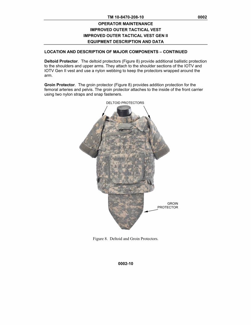
LOCATION AND DESCRIPTION OF MAJOR COMPONENTS – CONTINUED Deltoid Protector. The deltoid protectors (Figure 8) provide additional ballistic protection to the shoulders and upper arms. They attach to the shoulder sections of the IOTV and IOTV Gen II vest and use a nylon webbing to keep the protectors wrapped around the arm. Groin Protector. The groin protector (Figure 8) provides addition protection for the femoral arteries and pelvis. The groin protector attaches to the inside of the front carrier using two nylon straps and snap fasteners.
Figure 8. Deltoid and Groin Protectors.
DELTOID PROTECTORS
GROIN PROTECTOR
TM 10-8470-208-10 0002 OPERATOR MAINTENANCE
IMPROVED OUTER TACTICAL VEST IMPROVED OUTER TACTICAL VEST GEN II
EQUIPMENT DESCRIPTION AND DATA
0002-11
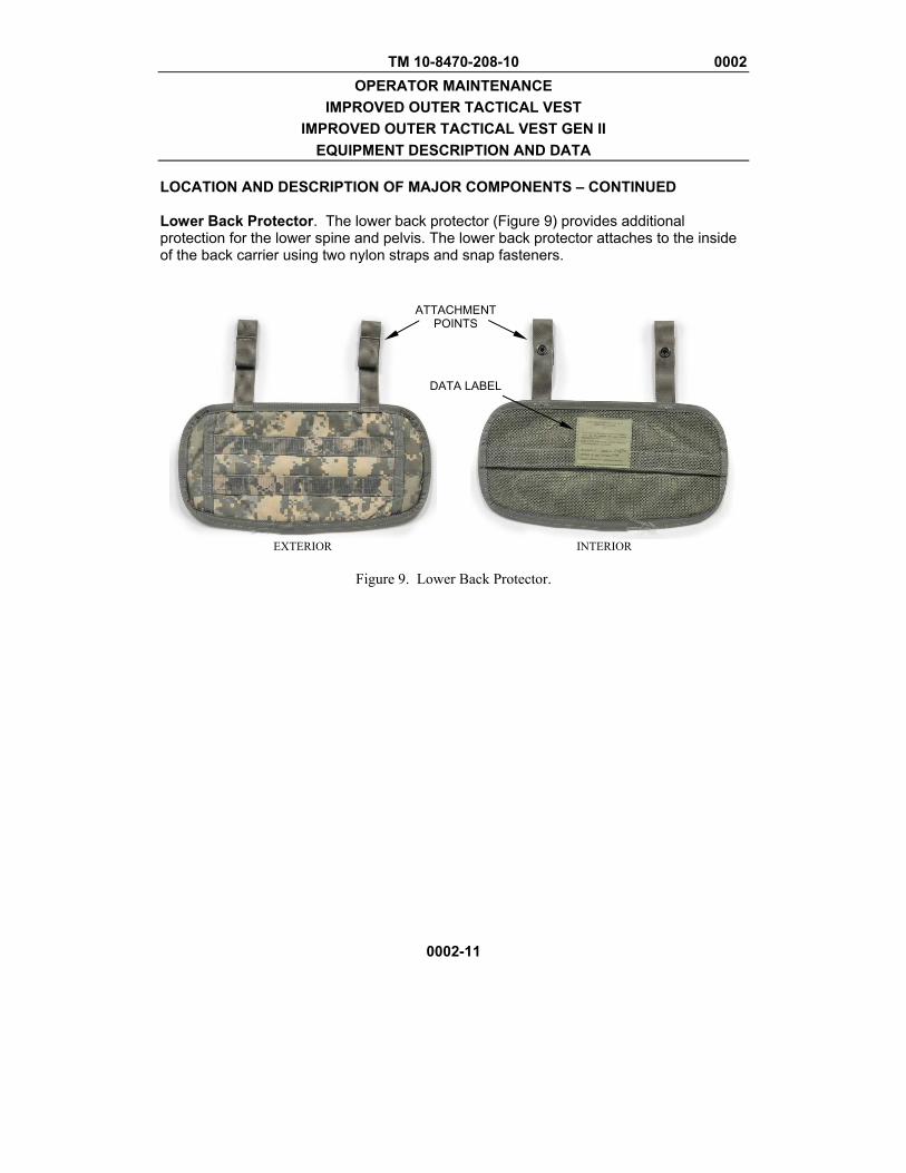
LOCATION AND DESCRIPTION OF MAJOR COMPONENTS – CONTINUED Lower Back Protector. The lower back protector (Figure 9) provides additional protection for the lower spine and pelvis. The lower back protector attaches to the inside of the back carrier using two nylon straps and snap fasteners.
EXTERIOR INTERIOR
Figure 9. Lower Back Protector.
ATTACHMENT POINTS
DATA LABEL
TM 10-8470-208-10 0002 OPERATOR MAINTENANCE
IMPROVED OUTER TACTICAL VEST IMPROVED OUTER TACTICAL VEST GEN II
EQUIPMENT DESCRIPTION AND DATA
0002-12
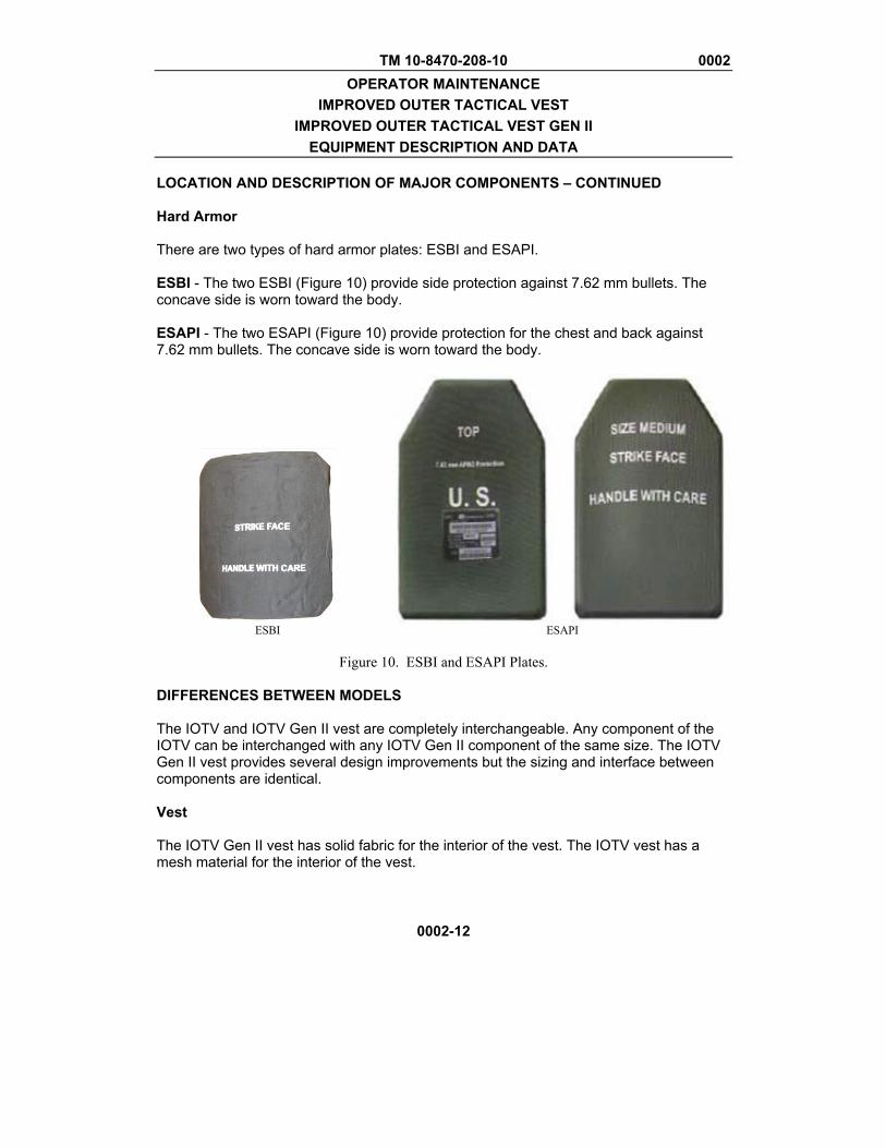
LOCATION AND DESCRIPTION OF MAJOR COMPONENTS – CONTINUED Hard Armor There are two types of hard armor plates: ESBI and ESAPI. ESBI - The two ESBI (Figure 10) provide side protection against 7.62 mm bullets. The concave side is worn toward the body. ESAPI - The two ESAPI (Figure 10) provide protection for the chest and back against 7.62 mm bullets. The concave side is worn toward the body.
ESBI ESAPI
Figure 10. ESBI and ESAPI Plates.
DIFFERENCES BETWEEN MODELS The IOTV and IOTV Gen II vest are completely interchangeable. Any component of the IOTV can be interchanged with any IOTV Gen II component of the same size. The IOTV Gen II vest provides several design improvements but the sizing and interface between components are identical. Vest The IOTV Gen II vest has solid fabric for the interior of the vest. The IOTV vest has a mesh material for the interior of the vest.
TM 10-8470-208-10 0002 OPERATOR MAINTENANCE
IMPROVED OUTER TACTICAL VEST IMPROVED OUTER TACTICAL VEST GEN II
EQUIPMENT DESCRIPTION AND DATA
0002-13
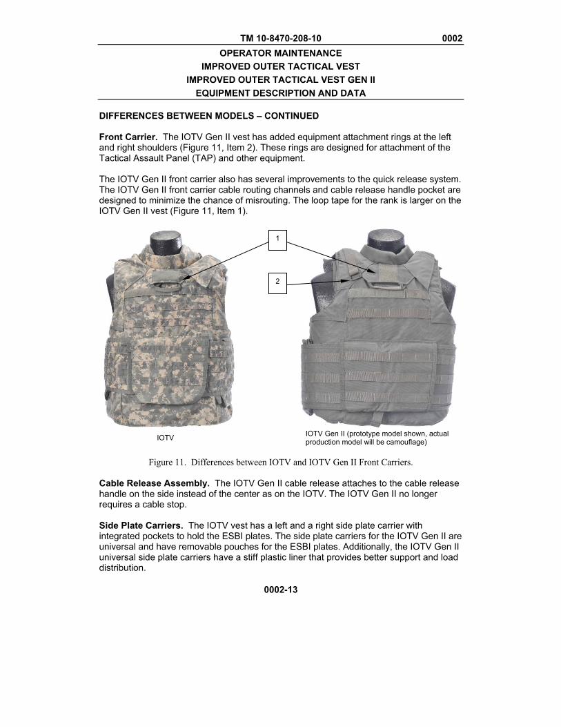
DIFFERENCES BETWEEN MODELS – CONTINUED Front Carrier. The IOTV Gen II vest has added equipment attachment rings at the left and right shoulders (Figure 11, Item 2). These rings are designed for attachment of the Tactical Assault Panel (TAP) and other equipment. The IOTV Gen II front carrier also has several improvements to the quick release system. The IOTV Gen II front carrier cable routing channels and cable release handle pocket are designed to minimize the chance of misrouting. The loop tape for the rank is larger on the IOTV Gen II vest (Figure 11, Item 1).
IOTV IOTV Gen II (prototype model shown, actual
production model will be camouflage)
Figure 11. Differences between IOTV and IOTV Gen II Front Carriers. Cable Release Assembly. The IOTV Gen II cable release attaches to the cable release handle on the side instead of the center as on the IOTV. The IOTV Gen II no longer requires a cable stop. Side Plate Carriers. The IOTV vest has a left and a right side plate carrier with integrated pockets to hold the ESBI plates. The side plate carriers for the IOTV Gen II are universal and have removable pouches for the ESBI plates. Additionally, the IOTV Gen II universal side plate carriers have a stiff plastic liner that provides better support and load distribution.
1
2

TM 10-8470-208-10 0002 OPERATOR MAINTENANCE
IMPROVED OUTER TACTICAL VEST IMPROVED OUTER TACTICAL VEST GEN II
EQUIPMENT DESCRIPTION AND DATA
0002-14
DIFFERENCES BETWEEN MODELS – CONTINUED Internal Elastic Bands. On the IOTV, one of the internal elastic bands is semi-permanently attached to the back carrier. On the IOTV Gen II, both internal elastic bands are detached. Lower Back Protector. The IOTV lower back protector has MOLLE webbing and a pocket. The IOTV Gen II does not. EQUIPMENT DATA IOTV Component Data Vest Sizes .............................................................. XS, S, M, ML, L, LL, XL, XLL, 2XL, 3XL, 4XL Protection ............................................................................................ 9 mm, Fragmentation Right and Left Side Plate Carriers Sizes ....................................................................................... XS-S, M-L, XL-2XL, 3XL-4XL Right and Left Internal Elastic Bands Sizes ....................................................................................... XS-S, M-L, XL-2XL, 3XL-4XL Cable Release Assembly Sizes ....................................................................................... XS-S, M-L, XL-2XL, 3XL-4XL Yoke/Collar Assembly Sizes (Front) ........................................................................................................... One Size Sizes (Back) ........................................................................ XS, S, M, L, XL, 2XL, 3XL, 4XL Protection ....................................................................................................... Fragmentation Groin Protector Sizes .................................................................................................................. S-ML, L-4XL Protection ............................................................................................ 9 mm, Fragmentation Lower Back Protector Sizes ....................................................................................................................... One Size Protection ............................................................................................ 9 mm, Fragmentation Deltoid Protectors Sizes ....................................................................................................... XS-S, M-L, XL-4XL Protection ............................................................................................ 9 mm, Fragmentation
TM 10-8470-208-10 0002 OPERATOR MAINTENANCE
IMPROVED OUTER TACTICAL VEST IMPROVED OUTER TACTICAL VEST GEN II
EQUIPMENT DESCRIPTION AND DATA
0002-15
EQUIPMENT DATA – CONTINUED IOTV Gen II Component Data Vest Sizes ............................................................... XS, S, M, ML,L, LL, XL, XLL, 2XL, 3XL, 4XL Protection ............................................................................................ 9 mm, Fragmentation Universal Side Plate Carriers Sizes ....................................................................................... XS-S, M-L, XL-2XL, 3XL-4XL Universal Side Plate Pouch Sizes ....................................................................................................................... One Size Right and Left Internal Elastic Bands Sizes ....................................................................................... XS-S, M-L, XL-2XL, 3XL-4XL Cable Release Assembly Sizes ....................................................................................... XS-S, M-L, XL-2XL, 3XL-4XL Yoke/Collar Assembly Sizes (Front) ........................................................................................................... One Size Sizes (Back) ........................................................................ XS, S, M, L, XL, 2XL, 3XL, 4XL Protection ....................................................................................................... Fragmentation Groin Protector Sizes .................................................................................................................. S-ML, L-4XL Protection ............................................................................................ 9 mm, Fragmentation Lower Back Protector Sizes ........................................................................................................................ One size Protection ............................................................................................ 9 mm, Fragmentation Deltoid Protectors Sizes ....................................................................................................... XS-S, M-L, XL-4XL Protection ............................................................................................ 9 mm, Fragmentation
TM 10-8470-208-10 0002 OPERATOR MAINTENANCE
IMPROVED OUTER TACTICAL VEST IMPROVED OUTER TACTICAL VEST GEN II
EQUIPMENT DESCRIPTION AND DATA
0002-16
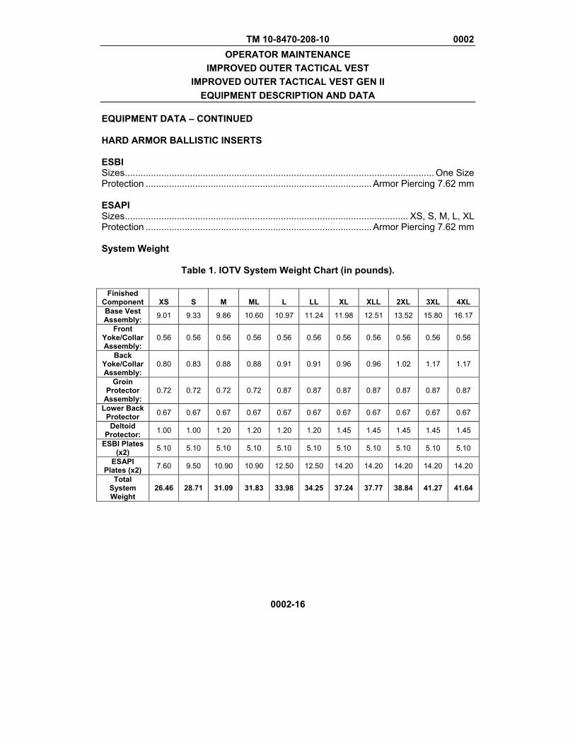
EQUIPMENT DATA – CONTINUED HARD ARMOR BALLISTIC INSERTS ESBI Sizes ....................................................................................................................... One Size Protection ....................................................................................... Armor Piercing 7.62 mm ESAPI Sizes ............................................................................................................. XS, S, M, L, XL Protection ....................................................................................... Armor Piercing 7.62 mm System Weight
Table 1. IOTV System Weight Chart (in pounds).
Finished Component XS S M ML L LL XL XLL 2XL 3XL 4XL Base Vest Assembly: 9.01 9.33 9.86 10.60 10.97 11.24 11.98 12.51 13.52 15.80 16.17
Front Yoke/Collar Assembly:
0.56 0.56 0.56 0.56 0.56 0.56 0.56 0.56 0.56 0.56 0.56
Back Yoke/Collar Assembly:
0.80 0.83 0.88 0.88 0.91 0.91 0.96 0.96 1.02 1.17 1.17
Groin Protector
Assembly: 0.72 0.72 0.72 0.72 0.87 0.87 0.87 0.87 0.87 0.87 0.87
Lower Back Protector 0.67 0.67 0.67 0.67 0.67 0.67 0.67 0.67 0.67 0.67 0.67
Deltoid Protector: 1.00 1.00 1.20 1.20 1.20 1.20 1.45 1.45 1.45 1.45 1.45
ESBI Plates (x2) 5.10 5.10 5.10 5.10 5.10 5.10 5.10 5.10 5.10 5.10 5.10
ESAPI Plates (x2) 7.60 9.50 10.90 10.90 12.50 12.50 14.20 14.20 14.20 14.20 14.20
Total System Weight
26.46 28.71 31.09 31.83 33.98 34.25 37.24 37.77 38.84 41.27 41.64

TM 10-8470-208-10 0002 OPERATOR MAINTENANCE
IMPROVED OUTER TACTICAL VEST IMPROVED OUTER TACTICAL VEST GEN II
EQUIPMENT DESCRIPTION AND DATA
0002-17/18 blank
EQUIPMENT DATA – CONTINUED
Table 2. IOTV Gen II System Weight Chart (in pounds).
Finished Component XS S M ML L LL XL XLL 2XL 3XL 4XL Base Vest Assembly: 9.61 9.93 0.56 11.30 1.72 11.99 12.78 13.31 14.32 16.60 16.97
Front Yoke/Collar Assembly:
0.56 0.56 0.56 0.56 0.56 0.56 0.56 0.56 0.56 0.56 0.56
Back Yoke/Collar Assembly:
0.80 0.83 0.88 0.88 0.91 0.91 0.96 0.96 1.02 1.17 1.23
Groin Protector
Assembly: 0.72 0.72 0.72 0.72 0.87 0.87 0.87 0.87 0.87 0.87 0.87
Lower Back Protector 0.67 0.67 0.67 0.67 0.67 0.67 0.67 0.67 0.67 0.67 0.67
Deltoid Protector: 2.00 2.00 2.40 2.40 2.40 2.40 2.90 2.90 2.90 2.90 2.90
ESBI Plates (x2) 5.10 5.10 5.10 5.10 5.10 5.10 5.10 5.10 5.10 5.10 5.10
ESAPI Plates (x2) 7.60 9.50 10.90 10.90 12.50 12.50 14.20 14.20 14.20 14.20 14.20
Total System Weight 27.06 26.31 31.69 32.53 34.73 35.00 38.04 38.57 39.64 42.07 42.50
END OF WORK PACKAGE

TM 10-8470-208-10 0003 OPERATOR MAINTENANCE
IMPROVED OUTER TACTICAL VEST IMPROVED OUTER TACTICAL VEST GEN II
THEORY OF OPERATION
0003-1/2 blank
THEORY OF OPERATION Different field scenarios will require different levels of protection for the servicemember. Unit commanders will prescribe the level of protection required for a mission. The most basic configuration of the IOTV and IOTV Gen II consists of the front and rear carriers with soft ballistic inserts, two side plate carriers with side plate pouches, elastic internal waistband, and the quick release cable. The ancillary equipment provides protection for areas not covered by the basic configuration. The yoke and collar assembly provides protection for the shoulders and neck. The deltoid protectors provide protection for the shoulders and upper arms. The groin protector provides protection for the femoral arteries and pelvis. The lower back protector provides protection for the lower spine and pelvis. The next level of protection includes installing hard armor plates. Leave the soft ballistic protection in the vest when installing the hard armor and ensure the soft ballistic protection remains flat and smooth. Insert the side ballistic plates into the side plate pockets. The IBA is designed to protect the servicemember from small-arms fire to include 7.62 mm and 9 mm bullets as well as fragmentation. Each component of the IOTV is compatible with each piece of IOTV Gen II. Quick-Release Function The IOTV and IOTV Gen II vest have a quick release function designed to be used during emergency situations only. With the IOTV or IOTV Gen II assembled with some or all of the accessories, the quick release function can be used to doff the vest rapidly in emergency situations. Such situations could include needing quick access for medical attention, or needed to remove the vest quickly to swim. Once the function has been used, the vest can be reassembled easily to provide ballistic protection. END OF WORK PACKAGE

TM 10-8470-208-10
CHAPTER 2
OPERATOR INSTRUCTIONS FOR
IMPROVED OUTER TACTICAL VEST (IOTV) AND
IMPROVED OUTER TACTICAL VEST GEN II (IOTV GEN II)


TM 10-8470-208-10 0004 OPERATOR MAINTENANCE
IMPROVED OUTER TACTICAL VEST
IMPROVED OUTER TACTICAL VEST GEN II OPERATION UNDER USUAL CONDITIONS – ASSEMBLY
0004-1
INITIAL SETUP
References: WP 0002 WP 0008
ASSSEMBLY AND PREPARATION FOR USE Inventory Proper sizing of the IOTV and IOTV Gen II is critical to its ability to protect you from ballistic threats. This includes ensuring each component of your IBA system is the correct size.
NOTE
Any component of the IOTV is compatible with any component of the IOTV Gen II. When conducting inventory, any combination of components will make up a system as long as all components are present and properly sized.
1. Inventory system using Table 1.
a. Go to the first row in Table 1.
b. The first column lists the name of the component to be inventoried.
c. The second column indicates the quantity of that item required to make a complete IBA system (IOTV or IOTV Gen II configuration).
d. The third and fourth columns have pictures of each component for either the IOTV or IOTV Gen II. These columns also have notes to help identify the differences between the IOTV and IOTV Gen II versions of each component.
2. Check the interior side of each component for a data label.
3. Ensure each component is the correct size for your system as indicated in Table 2.
a. On the first row, find the size of your IOTV or IOTV Gen II.
b. As you inventory each component, find that component in the left-most column of Table 2.
c. The correct size for each component is listed at the intersection of the row the individual component is listed on and the column that lists the size of your vest.
4. If a component is not the correct size or if it does not have a data label, turn it in for a properly sized component.
5. Inspect each component using Table 1, WP 0008, Preventive Maintenance Checks and Services.
TM 10-8470-208-10 0004 OPERATOR MAINTENANCE
IMPROVED OUTER TACTICAL VEST
IMPROVED OUTER TACTICAL VEST GEN II OPERATION UNDER USUAL CONDITIONS – ASSEMBLY
0004-2
ASSSEMBLY AND PREPARATION FOR USE - CONTINUED
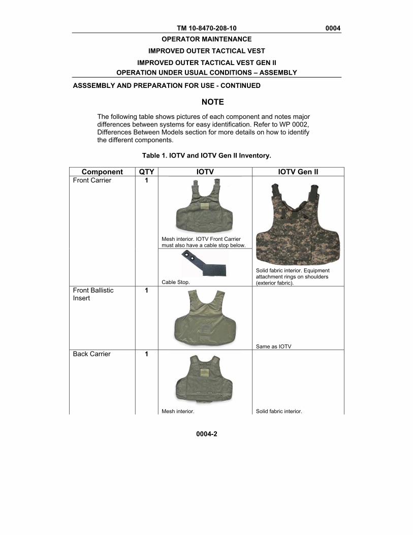
NOTE
The following table shows pictures of each component and notes major differences between systems for easy identification. Refer to WP 0002, Differences Between Models section for more details on how to identify the different components.
Table 1. IOTV and IOTV Gen II Inventory.
Component QTY IOTV IOTV Gen II
Front Carrier 1
Mesh interior. IOTV Front Carrier must also have a cable stop below.
Solid fabric interior. Equipment attachment rings on shoulders (exterior fabric).
Cable Stop.
Front Ballistic Insert
1
Same as IOTV Back Carrier 1
Mesh interior. Solid fabric interior.
TM 10-8470-208-10 0004 OPERATOR MAINTENANCE
IMPROVED OUTER TACTICAL VEST
IMPROVED OUTER TACTICAL VEST GEN II OPERATION UNDER USUAL CONDITIONS – ASSEMBLY
ASSEMBLY AND PREPARATION FOR USE – CONTINUED
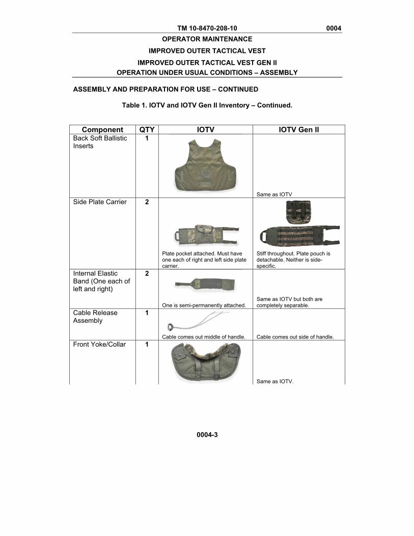
Table 1. IOTV and IOTV Gen II Inventory – Continued.
0004-3
Component QTY IOTV IOTV Gen II Back Soft Ballistic Inserts
1
Same as IOTV Side Plate Carrier 2
Plate pocket attached. Must have one each of right and left side plate carrier.
Stiff throughout. Plate pouch is detachable. Neither is side-specific.
Internal Elastic Band (One each of left and right)
2
One is semi-permanently attached.
Same as IOTV but both are completely separable.
Cable Release Assembly
1
Cable comes out middle of handle.
Cable comes out side of handle.
Front Yoke/Collar 1
Same as IOTV.
TM 10-8470-208-10 0004 OPERATOR MAINTENANCE
IMPROVED OUTER TACTICAL VEST
IMPROVED OUTER TACTICAL VEST GEN II OPERATION UNDER USUAL CONDITIONS – ASSEMBLY
ASSEMBLY AND PREPARATION FOR USE – CONTINUED
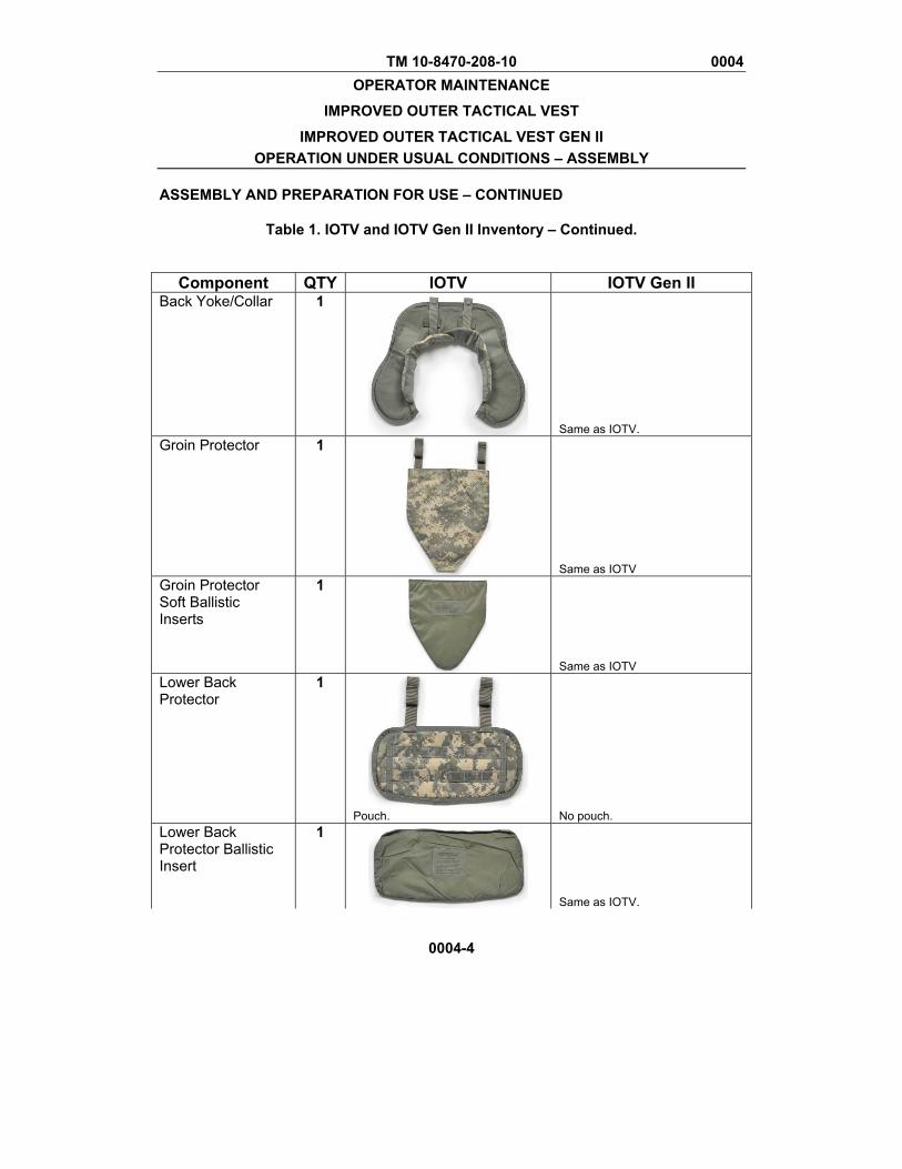
Table 1. IOTV and IOTV Gen II Inventory – Continued.
0004-4
Component QTY IOTV IOTV Gen II Back Yoke/Collar 1
Same as IOTV. Groin Protector 1
Same as IOTV Groin Protector Soft Ballistic Inserts
1
Same as IOTV Lower Back Protector
1
Pouch. No pouch.
Lower Back Protector Ballistic Insert
1
Same as IOTV.
TM 10-8470-208-10 0004 OPERATOR MAINTENANCE
IMPROVED OUTER TACTICAL VEST
IMPROVED OUTER TACTICAL VEST GEN II OPERATION UNDER USUAL CONDITIONS – ASSEMBLY
ASSEMBLY AND PREPARATION FOR USE – CONTINUED
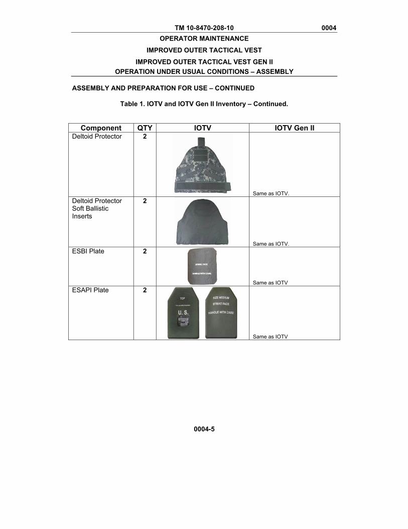
Table 1. IOTV and IOTV Gen II Inventory – Continued.
0004-5
Component QTY IOTV IOTV Gen II Deltoid Protector 2
Same as IOTV. Deltoid Protector Soft Ballistic Inserts
2
Same as IOTV. ESBI Plate 2
Same as IOTV ESAPI Plate 2
Same as IOTV
TM 10-8470-208-10 0004 OPERATOR MAINTENANCE
IMPROVED OUTER TACTICAL VEST
IMPROVED OUTER TACTICAL VEST GEN II OPERATION UNDER USUAL CONDITIONS – ASSEMBLY
ASSEMBLY AND PREPARATION FOR USE – CONTINUED
0004-6
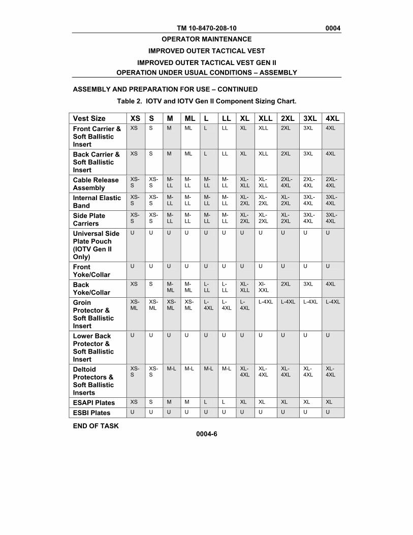
Table 2. IOTV and IOTV Gen II Component Sizing Chart.
Vest Size XS S M ML L LL XL XLL 2XL 3XL 4XL Front Carrier & Soft Ballistic Insert
XS S M ML L LL XL XLL 2XL 3XL 4XL
Back Carrier & Soft Ballistic Insert
XS S M ML L LL XL XLL 2XL 3XL 4XL
Cable Release Assembly
XS-S
XS-S
M-LL
M-LL
M-LL
M-LL
XL-XLL
XL-XLL
2XL-4XL
2XL-4XL
2XL-4XL
Internal Elastic Band
XS-S
XS-S
M-LL
M-LL
M-LL
M-LL
XL-2XL
XL-2XL
XL-2XL
3XL-4XL
3XL-4XL
Side Plate Carriers
XS-S
XS-S
M-LL
M-LL
M-LL
M-LL
XL-2XL
XL-2XL
XL-2XL
3XL-4XL
3XL-4XL
Universal Side Plate Pouch (IOTV Gen II Only)
U U U U U U U U U U U
Front Yoke/Collar
U U U U U U U U U U U
Back Yoke/Collar
XS S M-ML
M-ML
L-LL
L-LL
XL-XLL
Xl-XXL
2XL 3XL 4XL
Groin Protector & Soft Ballistic Insert
XS-ML
XS-ML
XS-ML
XS-ML
L-4XL
L-4XL
L-4XL
L-4XL L-4XL L-4XL L-4XL
Lower Back Protector & Soft Ballistic Insert
U U U U U U U U U U U
Deltoid Protectors & Soft Ballistic Inserts
XS-S
XS-S
M-L M-L M-L M-L XL-4XL
XL-4XL
XL-4XL
XL-4XL
XL-4XL
ESAPI Plates XS S M M L L XL XL XL XL XL
ESBI Plates U U U U U U U U U U U
END OF TASK

TM 10-8470-208-10 0004 OPERATOR MAINTENANCE
IMPROVED OUTER TACTICAL VEST
IMPROVED OUTER TACTICAL VEST GEN II OPERATION UNDER USUAL CONDITIONS – ASSEMBLY
ASSEMBLY AND PREPARATION FOR USE – CONTINUED
0004-7
Assemble IOTV or IOTV Gen II
WARNING
Ensure the sizes of the front and back carrier match by comparing data plate information. Ensure the sizes of the attachable items match the sizes of the front and back carriers by comparing data plate information. Failure to do so could affect performance, causing injury or death to the servicemember.
NOTE
The term “interior fabric” or “interior surface” means the side of any component of the IBA system that faces the soldier when worn. The term “exterior fabric” or “exterior surface” means the side of any component of the IBA system that faces away from the soldier. The term “inside surface,” “inside fabric” or “inside” means the area of any IBA component that is between the exterior and interior surfaces. The inside or inside surface of an IBA component is the portion that touches the soft ballistic inserts.
Inserting Soft Ballistic Inserts. 1. Place the carrier on a clean surface with the exterior surface facing down.
2. Place the soft ballistic insert on top of the carrier with the data label facing up (Figure 1).
Figure 1. Placing Carrier Exterior Fabric Down.
TM 10-8470-208-10 0004 OPERATOR MAINTENANCE
IMPROVED OUTER TACTICAL VEST
IMPROVED OUTER TACTICAL VEST GEN II OPERATION UNDER USUAL CONDITIONS – ASSEMBLY
ASSEMBLY AND PREPARATION FOR USE – CONTINUED
0004-8
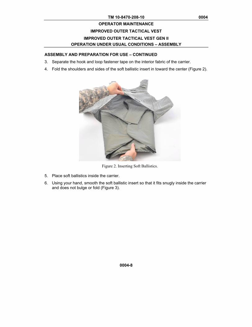
3. Separate the hook and loop fastener tape on the interior fabric of the carrier.
4. Fold the shoulders and sides of the soft ballistic insert in toward the center (Figure 2).
Figure 2. Inserting Soft Ballistics.
5. Place soft ballistics inside the carrier.
6. Using your hand, smooth the soft ballistic insert so that it fits snugly inside the carrier and does not bulge or fold (Figure 3).
TM 10-8470-208-10 0004 OPERATOR MAINTENANCE
IMPROVED OUTER TACTICAL VEST
IMPROVED OUTER TACTICAL VEST GEN II OPERATION UNDER USUAL CONDITIONS – ASSEMBLY
ASSEMBLY AND PREPARATION FOR USE – CONTINUED
0004-9
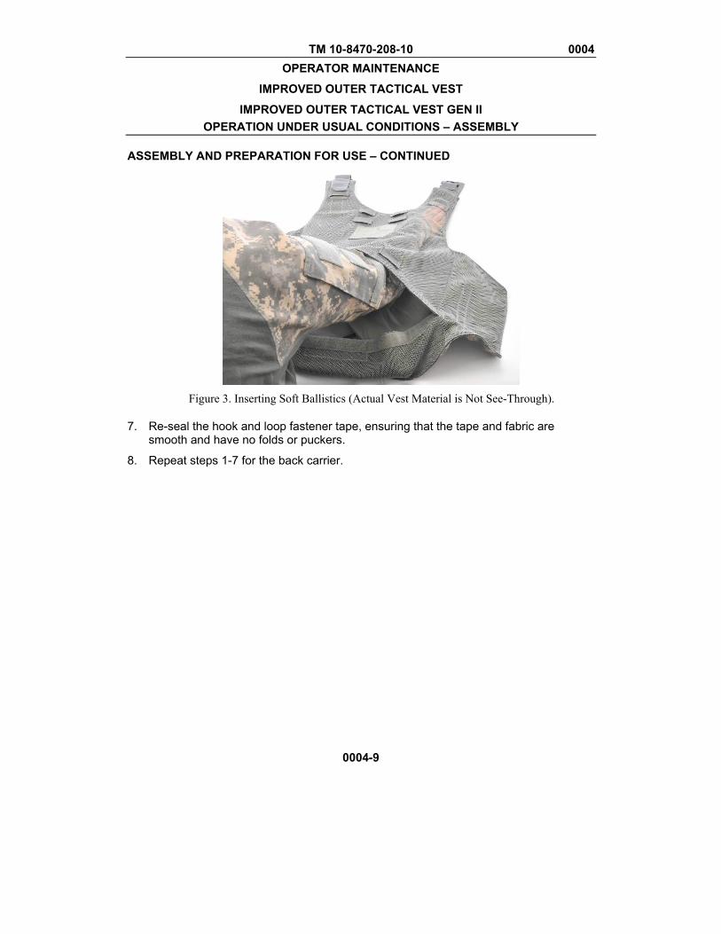
Figure 3. Inserting Soft Ballistics (Actual Vest Material is Not See-Through).
7. Re-seal the hook and loop fastener tape, ensuring that the tape and fabric are smooth and have no folds or puckers.
8. Repeat steps 1-7 for the back carrier.
TM 10-8470-208-10 0004 OPERATOR MAINTENANCE
IMPROVED OUTER TACTICAL VEST
IMPROVED OUTER TACTICAL VEST GEN II OPERATION UNDER USUAL CONDITIONS – ASSEMBLY
ASSEMBLY AND PREPARATION FOR USE – CONTINUED
0004-10
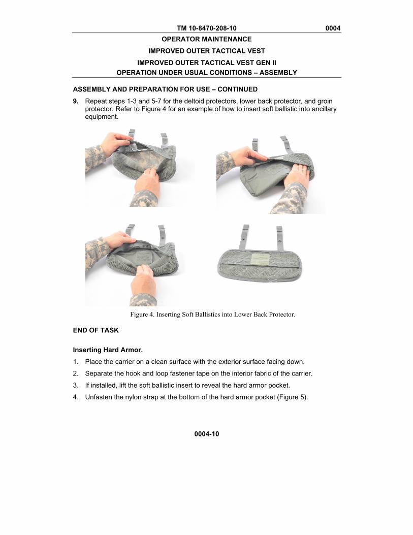
9. Repeat steps 1-3 and 5-7 for the deltoid protectors, lower back protector, and groin protector. Refer to Figure 4 for an example of how to insert soft ballistic into ancillary equipment.
Figure 4. Inserting Soft Ballistics into Lower Back Protector.
END OF TASK
Inserting Hard Armor.
1. Place the carrier on a clean surface with the exterior surface facing down.
2. Separate the hook and loop fastener tape on the interior fabric of the carrier.
3. If installed, lift the soft ballistic insert to reveal the hard armor pocket.
4. Unfasten the nylon strap at the bottom of the hard armor pocket (Figure 5).

TM 10-8470-208-10 0004 OPERATOR MAINTENANCE
IMPROVED OUTER TACTICAL VEST
IMPROVED OUTER TACTICAL VEST GEN II OPERATION UNDER USUAL CONDITIONS – ASSEMBLY
ASSEMBLY AND PREPARATION FOR USE – CONTINUED
0004-11
Figure 5. Opening Hard Armor Protective Insert Pocket.
5. Place ESAPI plate into the hard armor pocket with the concave side up (Figure 6).
Figure 6. Inserting Hard Armor Protective Insert.
TM 10-8470-208-10 0004 OPERATOR MAINTENANCE
IMPROVED OUTER TACTICAL VEST
IMPROVED OUTER TACTICAL VEST GEN II OPERATION UNDER USUAL CONDITIONS – ASSEMBLY
ASSEMBLY AND PREPARATION FOR USE – CONTINUED
0004-12
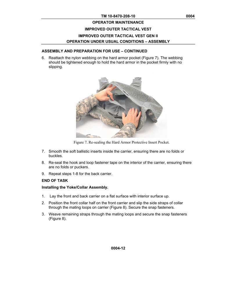
6. Reattach the nylon webbing on the hard armor pocket (Figure 7). The webbing should be tightened enough to hold the hard armor in the pocket firmly with no slipping.
Figure 7. Re-sealing the Hard Armor Protective Insert Pocket.
7. Smooth the soft ballistic inserts inside the carrier, ensuring there are no folds or buckles.
8. Re-seal the hook and loop fastener tape on the interior of the carrier, ensuring there are no folds or puckers.
9. Repeat steps 1-8 for the back carrier.
END OF TASK
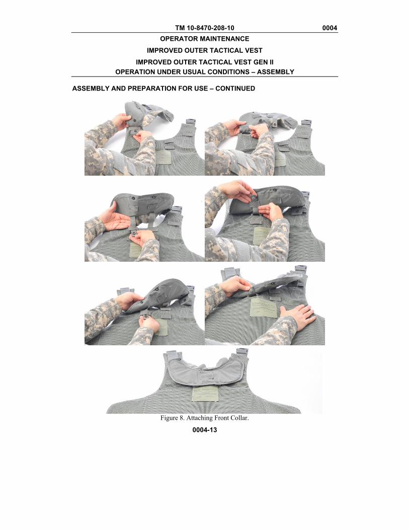
Installing the Yoke/Collar Assembly. 1. Lay the front and back carrier on a flat surface with interior surface up.
2. Position the front collar half on the front carrier and slip the side straps of collar through the mating loops on carrier (Figure 8). Secure the snap fasteners.
3. Weave remaining straps through the mating loops and secure the snap fasteners (Figure 8).
TM 10-8470-208-10 0004 OPERATOR MAINTENANCE
IMPROVED OUTER TACTICAL VEST
IMPROVED OUTER TACTICAL VEST GEN II OPERATION UNDER USUAL CONDITIONS – ASSEMBLY
ASSEMBLY AND PREPARATION FOR USE – CONTINUED
0004-13
Figure 8. Attaching Front Collar.
TM 10-8470-208-10 0004 OPERATOR MAINTENANCE
IMPROVED OUTER TACTICAL VEST
IMPROVED OUTER TACTICAL VEST GEN II OPERATION UNDER USUAL CONDITIONS – ASSEMBLY
ASSEMBLY AND PREPARATION FOR USE – CONTINUED
0004-14
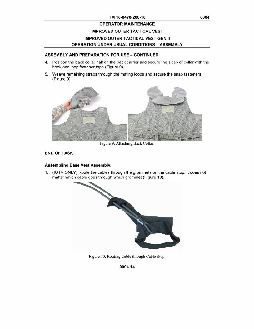
4. Position the back collar half on the back carrier and secure the sides of collar with the hook and loop fastener tape (Figure 9).
5. Weave remaining straps through the mating loops and secure the snap fasteners (Figure 9).
Figure 9. Attaching Back Collar.
END OF TASK
Assembling Base Vest Assembly.
1. (IOTV ONLY) Route the cables through the grommets on the cable stop. It does not matter which cable goes through which grommet (Figure 10).
Figure 10. Routing Cable through Cable Stop.

TM 10-8470-208-10 0004 OPERATOR MAINTENANCE
IMPROVED OUTER TACTICAL VEST
IMPROVED OUTER TACTICAL VEST GEN II OPERATION UNDER USUAL CONDITIONS – ASSEMBLY
ASSEMBLY AND PREPARATION FOR USE – CONTINUED
0004-15
WARNING
Ensure there are no kinks in the quick-release cable. Failure to do so could adversely affect the function of the quick-release, causing injury or death to the service member. Ensure the appropriate sized cable assembly is used according to the vest size.
(IOTV ONLY) Ensure the quick-release cable is routed through the two grommets of the cable stop, or a malfunction may occur. It does not matter which cable is routed through which grommet.
2. Insert the cable through the release cable pocket and route through the right shoulder (Figure 11).
a. (IOTV ONLY) Continue to route cable through the release cable webbing channel on the right shoulder of the front carrier (Figure 11).
Figure 11. Routing the Cable Release Assembly on Front Carrier.
CABLE RELEASE HANDLE POCKET
(IOTV ONLY) SEMI-DETACHED CABLE WEBBING
CHANNEL
(IOTV ONLY) CABLE STOP IS TUCKED IN CABLE RELEASE HANDLE POCKET

TM 10-8470-208-10 0004 OPERATOR MAINTENANCE
IMPROVED OUTER TACTICAL VEST
IMPROVED OUTER TACTICAL VEST GEN II OPERATION UNDER USUAL CONDITIONS – ASSEMBLY
ASSEMBLY AND PREPARATION FOR USE – CONTINUED
0004-16
3. Stow the cable-release handle in the cable release handle pocket and secure with the hook and loop patches inside the pocket.
4. Adjust right shoulder buckle so that the reducer buckle is even with the cable webbing channel (Figure 12).
Figure 12. Adjusting Left Shoulder Webbing Length.
5. Align the front and back carriers with the interior side down, right shoulder to right shoulder and left shoulder to left shoulder (Figure 13).
6. Route the right side buckles and cables from the front carrier through the shoulder strap guide of the back carrier. Route the left side buckle of the front carrier through the shoulder strap guide of the back carrier (Figure 13).
TM 10-8470-208-10 0004 OPERATOR MAINTENANCE
IMPROVED OUTER TACTICAL VEST
IMPROVED OUTER TACTICAL VEST GEN II OPERATION UNDER USUAL CONDITIONS – ASSEMBLY
ASSEMBLY AND PREPARATION FOR USE – CONTINUED
0004-17
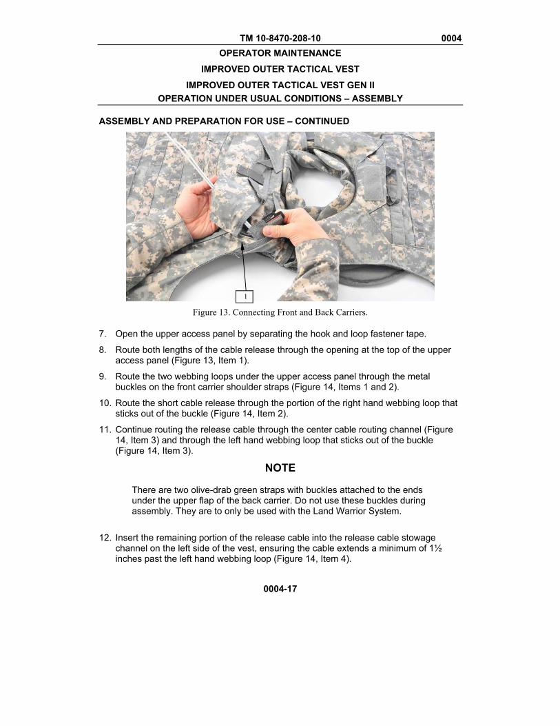
Figure 13. Connecting Front and Back Carriers.
7. Open the upper access panel by separating the hook and loop fastener tape.
8. Route both lengths of the cable release through the opening at the top of the upper access panel (Figure 13, Item 1).
9. Route the two webbing loops under the upper access panel through the metal buckles on the front carrier shoulder straps (Figure 14, Items 1 and 2).
10. Route the short cable release through the portion of the right hand webbing loop that sticks out of the buckle (Figure 14, Item 2).
11. Continue routing the release cable through the center cable routing channel (Figure 14, Item 3) and through the left hand webbing loop that sticks out of the buckle (Figure 14, Item 3).
NOTE
There are two olive-drab green straps with buckles attached to the ends under the upper flap of the back carrier. Do not use these buckles during assembly. They are to only be used with the Land Warrior System.
12. Insert the remaining portion of the release cable into the release cable stowage channel on the left side of the vest, ensuring the cable extends a minimum of 1½ inches past the left hand webbing loop (Figure 14, Item 4).
1
TM 10-8470-208-10 0004 OPERATOR MAINTENANCE
IMPROVED OUTER TACTICAL VEST
IMPROVED OUTER TACTICAL VEST GEN II OPERATION UNDER USUAL CONDITIONS – ASSEMBLY
ASSEMBLY AND PREPARATION FOR USE – CONTINUED
0004-18
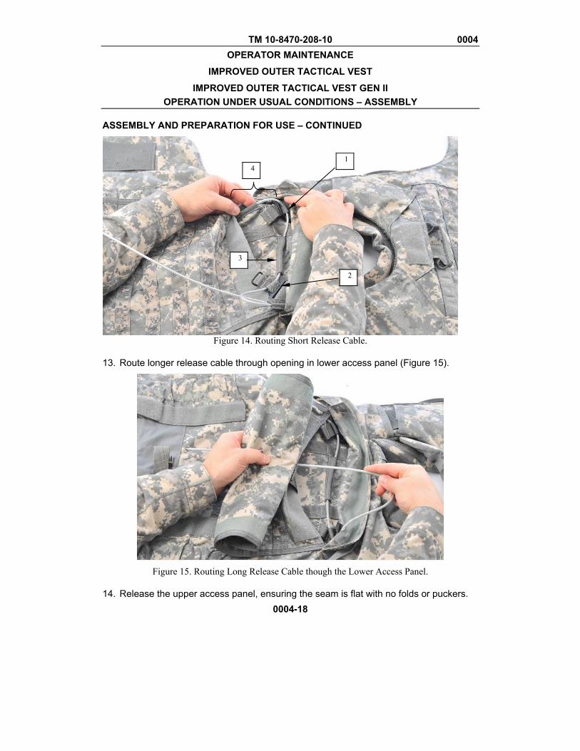
Figure 14. Routing Short Release Cable.
13. Route longer release cable through opening in lower access panel (Figure 15).
Figure 15. Routing Long Release Cable though the Lower Access Panel.
14. Release the upper access panel, ensuring the seam is flat with no folds or puckers.
1
3
4
2
TM 10-8470-208-10 0004 OPERATOR MAINTENANCE
IMPROVED OUTER TACTICAL VEST
IMPROVED OUTER TACTICAL VEST GEN II OPERATION UNDER USUAL CONDITIONS – ASSEMBLY
ASSEMBLY AND PREPARATION FOR USE – CONTINUED
0004-19
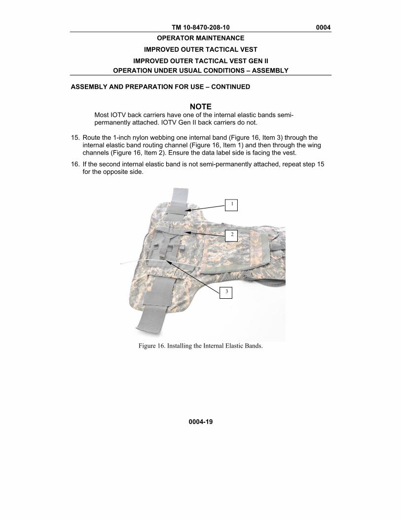
NOTE
Most IOTV back carriers have one of the internal elastic bands semi-permanently attached. IOTV Gen II back carriers do not.
15. Route the 1-inch nylon webbing one internal band (Figure 16, Item 3) through the
internal elastic band routing channel (Figure 16, Item 1) and then through the wing channels (Figure 16, Item 2). Ensure the data label side is facing the vest.
16. If the second internal elastic band is not semi-permanently attached, repeat step 15 for the opposite side.
Figure 16. Installing the Internal Elastic Bands.
2
3
1
TM 10-8470-208-10 0004 OPERATOR MAINTENANCE
IMPROVED OUTER TACTICAL VEST
IMPROVED OUTER TACTICAL VEST GEN II OPERATION UNDER USUAL CONDITIONS – ASSEMBLY
ASSEMBLY AND PREPARATION FOR USE – CONTINUED
0004-20
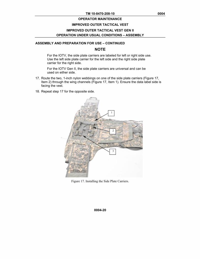
NOTE For the IOTV, the side plate carriers are labeled for left or right side use. Use the left side plate carrier for the left side and the right side plate carrier for the right side.
For the IOTV Gen II, the side plate carriers are universal and can be used on either side.
17. Route the two, 1-inch nylon webbings on one of the side plate carriers (Figure 17, Item 2) through the wing channels (Figure 17, Item 1). Ensure the data label side is facing the vest.
18. Repeat step 17 for the opposite side.
Figure 17. Installing the Side Plate Carriers.
3
2
1
TM 10-8470-208-10 0004 OPERATOR MAINTENANCE
IMPROVED OUTER TACTICAL VEST
IMPROVED OUTER TACTICAL VEST GEN II OPERATION UNDER USUAL CONDITIONS – ASSEMBLY
ASSEMBLY AND PREPARATION FOR USE – CONTINUED
0004-21
WARNING
Proper routing of the cable release assembly is critical to the proper operation of the vest during an emergency doffing. The left-hand side plate carrier (left side plate carrier for IOTV or left-hand universal side plate carrier for IOTV Gen II) should be attached first, followed by the right. Failure to follow these directions could result in injury or death.
19. Route the uppermost loop of 1-inch webbing through the rectangular ring at the end of the 1-inch nylon webbing on the right-hand side plate carrier and then through the left-hand side plate carrier. Refer to Figure 18 for the sequence.
20. If one of the internal elastic bands is semi-permanent attached, route the middle loop of 1-inch webbing through the rectangular ring at the end of the opposite internal elastic band. If both elastic bands are permanently detached, then route the loop of 1-inch webbing through one internal elastic band and then through the second internal elastic band. Refer to Figure 18 for sequence.
21. Route the lowermost loop of 1-inch webbing through the rectangular ring at the end of the 1-inch nylon webbing on the right-hand side plate carrier and then through the left-hand side plate carrier. Refer to Figure 18 for the sequence.
22. Ensuring the 1-inch nylon webbing does not come out of the rectangular rings, route the long release cable through all three loops from top to bottom (Figure18).
23. Tuck the end of the release cable into the cable stowage pocket, ensuring a minimum of 1 ½ inches of cable extend past the last webbing loop (Figure 18).
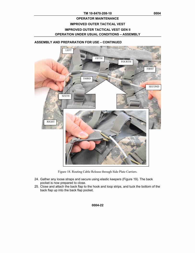
TM 10-8470-208-10 0004 OPERATOR MAINTENANCE
IMPROVED OUTER TACTICAL VEST
IMPROVED OUTER TACTICAL VEST GEN II OPERATION UNDER USUAL CONDITIONS – ASSEMBLY
ASSEMBLY AND PREPARATION FOR USE – CONTINUED
0004-22
Figure 18. Routing Cable Release through Side Plate Carriers.
24. Gather any loose straps and secure using elastic keepers (Figure 19). The back pocket is now prepared to close.
25. Close and attach the back flap to the hook and loop strips, and tuck the bottom of the back flap up into the back flap pocket.
SECOND
FIRST
FOURTH
THIRD
FIFTH
SIXTH
LEFT
RIGHT
TM 10-8470-208-10 0004 OPERATOR MAINTENANCE
IMPROVED OUTER TACTICAL VEST
IMPROVED OUTER TACTICAL VEST GEN II OPERATION UNDER USUAL CONDITIONS – ASSEMBLY
ASSEMBLY AND PREPARATION FOR USE – CONTINUED
0004-23
Figure 19. Long Release Cable Routing.
END OF TASK Installing the Ballistic Groin Protector and Lower Back Protector.
NOTE
The following procedures are identical for the lower back protector and the groin protector. The lower back protector attaches to the back carrier. The groin protector attaches to the front carrier.
1. Lay carrier on flat surface with interior surface facing up.
2. Insert both straps on groin protector (Figure 20) or lower back protector into the webbing loops on the carrier.
3. Fold over and secure the snap fasteners.
4. Ensure the data label faces the body when worn.
TM 10-8470-208-10 0004 OPERATOR MAINTENANCE
IMPROVED OUTER TACTICAL VEST
IMPROVED OUTER TACTICAL VEST GEN II OPERATION UNDER USUAL CONDITIONS – ASSEMBLY
ASSEMBLY AND PREPARATION FOR USE – CONTINUED
0004-24
Figure 20. Attaching Groin Protector.
Attaching the Deltoid Protectors.
WARNING
Do not include the flap of the back yoke when attaching the deltoid protector to the vest. Doing so may prevent the cable release from operating correctly.
NOTE
Deltoid protectors are universal. There is no right or left deltoid protector.
1. Unhook and fully extend deltoid protector upper attachment strap. Route the strap over and under the shoulder of the vest. For maximum protection, ensure the deltoid protector overlaps where the front and back shoulder joins. 2. Use the same procedure for attaching both right and left deltoid protectors. 3. Secure the deltoid protector around the arm by pulling the loose end of the attachment strap around the arm and securing the hook and loop material. END OF TASK

TM 10-8470-208-10 0004 OPERATOR MAINTENANCE
IMPROVED OUTER TACTICAL VEST
IMPROVED OUTER TACTICAL VEST GEN II OPERATION UNDER USUAL CONDITIONS – ASSEMBLY
ASSEMBLY AND PREPARATION FOR USE – CONTINUED
0004-25/26 blank
Inserting Side Hard Armor Plates (ESBI).
WARNING
During pre-combat inspections, check that side plate strap has an additional turn with the strap through the buckle for added security. Without the strap being properly secured, the plate could fall out, leaving the servicemember vulnerable to small-arms fire or fragmentation.
1. Lay the back carrier on flat surface with the interior material up and side plate
carriers folded out, exposing the side plate pockets. There are two methods to install the side ballistic plates.
2. Top Load Method (IOTV and IOTV Gen II):
a. The first method is to unfasten the hook and loop on the top flap of the
side plate pocket and pull out the flap and insert the side ballistic plate.
b. Push the plate into pocket, fold the flap back into pocket and re-attach the hook and loop fastener tape.
3. Bottom Load Method (IOTV ONLY):
a. The second method is to unweave the webbing from the buckle on the
bottom of the pouch.
b. Open the pouch and insert the plate with the concaved portion facing toward the inside.
c. Close the flap and weave the strap back through the buckle.
d. Route the end of the strap back through the buckle in the opposite
direction to lock.
4. If using the X-Small ESAPI plates instead of ESBI plates, insert the plate into unbuckled bottom flap and into the opened top flap. Buckle the bottom flap closed, ensuring to put the additional loop through the buckle to secure the strap.
END OF TASK END OF WORK PACKAGE

TM 10-8470-208-10 0005 OPERATOR MAINTENANCE
IMPROVED OUTER TACTICAL VEST
IMPROVED OUTER TACTICAL VEST GEN II OPERATION UNDER USUAL CONDITIONS – DON, DOFF, ADJUST
0005-1
INITIAL SETUP
References: WP 0004
DON
There are two methods to don the IOTV and IOTV Gen II. The primary method is the over-the-head method. The alternate method is over–the-shoulder method.
Prior to donning your body, attach all the components necessary to meet mission requirements.
NOTE
When the IBA is worn and adjusted correctly, there will be at least ½-inch overlap of fabric where the front and back carriers join at the shoulder.
1. Place vest on shoulder using the over-the-head method.
a. Open the left shoulder of the vest (medical access point) and unsnap the shoulder strap.
b. Loosen the left shoulder strap.
c. Place the vest over your head. (Figure 1).
Figure 1. Over the Head Donning.
TM 10-8470-208-10 0005 OPERATOR MAINTENANCE
IMPROVED OUTER TACTICAL VEST
IMPROVED OUTER TACTICAL VEST GEN II OPERATION UNDER USUAL CONDITIONS – DON, DOFF, ADJUST
0005-2
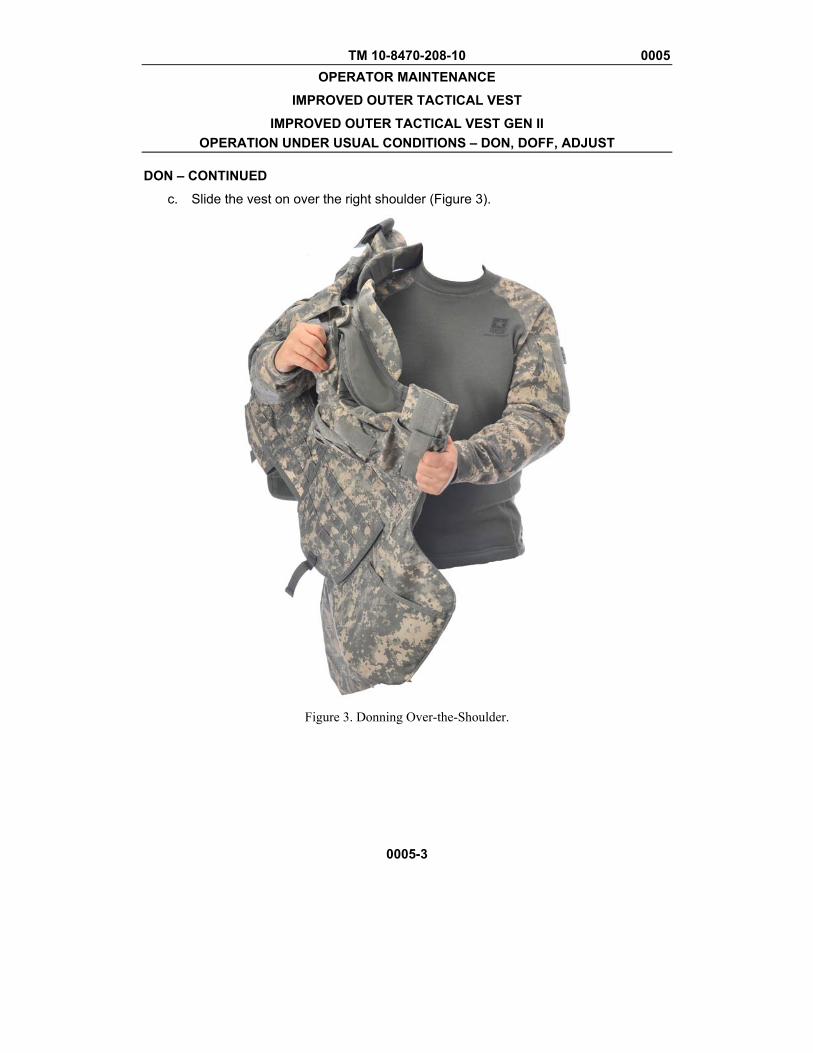
DON – CONTINUED
d. Pull on the left shoulder strap until tightened.
e. Secure left shoulder strap with hook and loop fastener tape and snap into place (Figure 2).
Figure 2. Adjusting Left Shoulder Strap.
2. Place vest on shoulder using the over-the-shoulder method.
a. Open the left shoulder of the vest (medical access point).
b. Completely separate the left shoulder strap from the front carrier.
TM 10-8470-208-10 0005 OPERATOR MAINTENANCE
IMPROVED OUTER TACTICAL VEST
IMPROVED OUTER TACTICAL VEST GEN II OPERATION UNDER USUAL CONDITIONS – DON, DOFF, ADJUST
0005-3
DON – CONTINUED
c. Slide the vest on over the right shoulder (Figure 3).
Figure 3. Donning Over-the-Shoulder.
TM 10-8470-208-10 0005 OPERATOR MAINTENANCE
IMPROVED OUTER TACTICAL VEST
IMPROVED OUTER TACTICAL VEST GEN II OPERATION UNDER USUAL CONDITIONS – DON, DOFF, ADJUST
0005-4
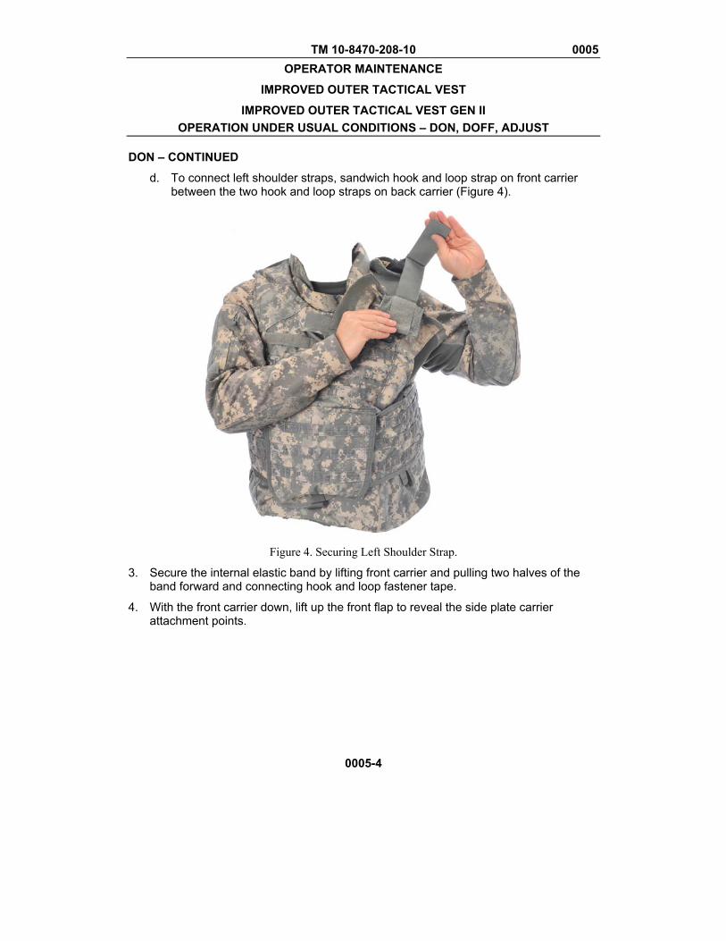
DON – CONTINUED
d. To connect left shoulder straps, sandwich hook and loop strap on front carrier between the two hook and loop straps on back carrier (Figure 4).
Figure 4. Securing Left Shoulder Strap.
3. Secure the internal elastic band by lifting front carrier and pulling two halves of the band forward and connecting hook and loop fastener tape.
4. With the front carrier down, lift up the front flap to reveal the side plate carrier attachment points.

TM 10-8470-208-10 0005 OPERATOR MAINTENANCE
IMPROVED OUTER TACTICAL VEST
IMPROVED OUTER TACTICAL VEST GEN II OPERATION UNDER USUAL CONDITIONS – DON, DOFF, ADJUST
0005-5
DON – CONTINUED
WARNING Ensure front and back carrier soft ballistic protection overlaps under the arm when donning the vest.
5. Pull one of the side plate carriers around the body and attach to same side hook and loop panel in front. Repeat the step with the other half. Ensure the hook material is square with the pile material and do not overlap (Figure 5).
Figure 5. Securing Side Plate Carriers.
6. Close the front flap, secure with hook and loop tape, and tuck the bottom of the front flap up into the front flap pocket.
7. If wearing deltoid protectors, secure to arms using arm strap IAW WP 0004.
END OF TASK
TM 10-8470-208-10 0005 OPERATOR MAINTENANCE
IMPROVED OUTER TACTICAL VEST
IMPROVED OUTER TACTICAL VEST GEN II OPERATION UNDER USUAL CONDITIONS – DON, DOFF, ADJUST
0005-6
DOFFING
There are three methods to doff the IOTV and IOTV Gen II. The primary method is the over-the-head method. The alternate method is over–the-shoulder method. This third method is the emergency release method.
WARNING The emergency release system should be used during emergencies or instructional purposes only. Using the cable release method to routinely doff the vest could result in damage to the hard armor plates. Damage to the hard armor plates could result in injury or death to the wearer.
NOTE Doffing the vest from the shoulder (over-the-head or over-the-shoulder) is the primary release method. Only use the cable-release in emergency situations or for instructional purposes.
1. If attached, remove the deltoid protector attachment straps from the arms.
2. Lift the front flap and detach side plate carriers by separating hook and loop fastener tape.
3. Lift front carrier and detach internal elastic bands at hook and loop interface.
4. Lift the vest over the head, or, separate the left shoulder strap and slide vest off the right shoulder.
Doffing – Cable Release Method
WARNING The cable release function is only to be used in emergency situations and for instructional purposes.
When using the cable release function, do not allow the plates to fall to a solid floor, such as concrete or tile. The impact may damage the hard armor plates and could compromise the effectiveness of the plates. Doing so could cause serious injury or death to wearer.
Grasp the cable release handle on top center of the front carrier and pull. The vest will separate into front and back halves.
END OF TASK
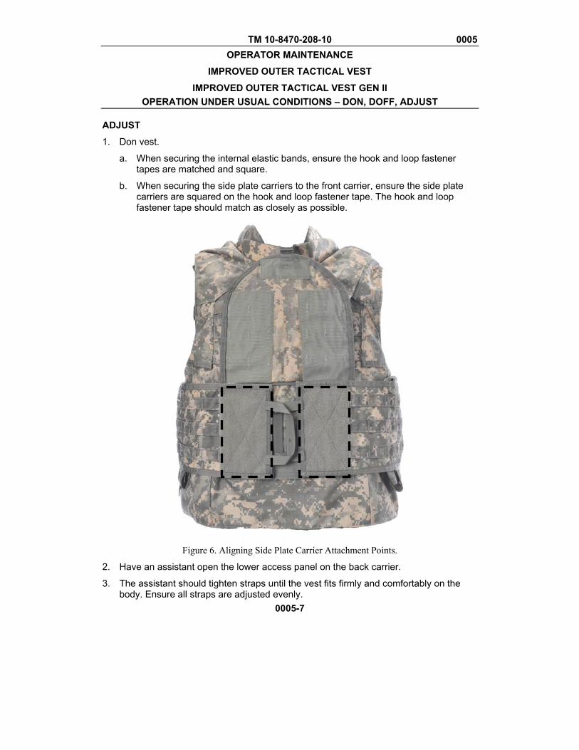
TM 10-8470-208-10 0005 OPERATOR MAINTENANCE
IMPROVED OUTER TACTICAL VEST
IMPROVED OUTER TACTICAL VEST GEN II OPERATION UNDER USUAL CONDITIONS – DON, DOFF, ADJUST
0005-7
ADJUST
1. Don vest.
a. When securing the internal elastic bands, ensure the hook and loop fastener tapes are matched and square.
b. When securing the side plate carriers to the front carrier, ensure the side plate carriers are squared on the hook and loop fastener tape. The hook and loop fastener tape should match as closely as possible.
Figure 6. Aligning Side Plate Carrier Attachment Points.
2. Have an assistant open the lower access panel on the back carrier.
3. The assistant should tighten straps until the vest fits firmly and comfortably on the body. Ensure all straps are adjusted evenly.
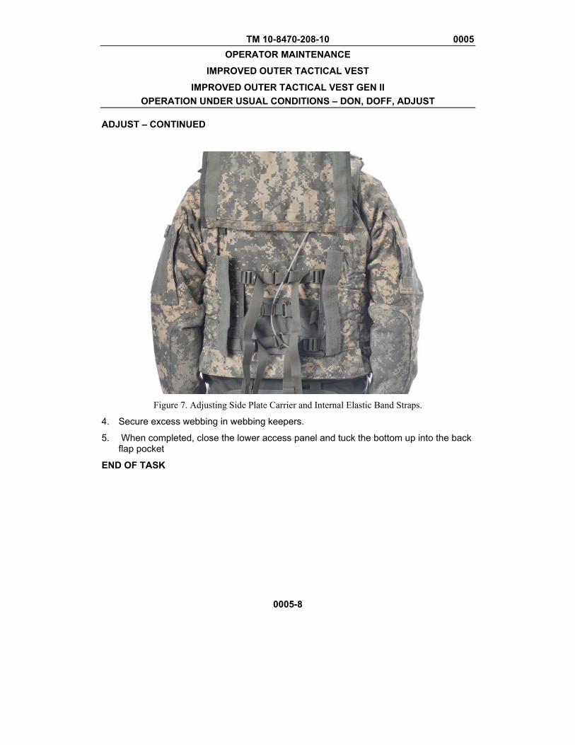
TM 10-8470-208-10 0005 OPERATOR MAINTENANCE
IMPROVED OUTER TACTICAL VEST
IMPROVED OUTER TACTICAL VEST GEN II OPERATION UNDER USUAL CONDITIONS – DON, DOFF, ADJUST
0005-8
ADJUST – CONTINUED
Figure 7. Adjusting Side Plate Carrier and Internal Elastic Band Straps.
4. Secure excess webbing in webbing keepers.
5. When completed, close the lower access panel and tuck the bottom up into the back flap pocket
END OF TASK
TM 10-8470-208-10 0006 OPERATOR MAINTENANCE
IMPROVED OUTER TACTICAL VEST IMPROVED OUTER TACTICAL VEST GEN II
OPERATION UNDER UNUSUAL CONDITIONS
0006-1/2 blank
INITIAL SETUP
References: FM 3.11.3
INTERCEPTOR BODY ARMOR (IBA) The IBA is constructed to function in various temperature ranges and displays resistance to potentially caustic elements such as salt water. Hard Armor Ballistic Inserts The hard armor ballistic inserts are designed to be structurally and ballistically functional from -60 to 160 degrees Fahrenheit. The inserts are also designed for resistance to fluids such as diesel, gasoline and salt water. The inserts can be immersed in these fluids up to two hours before functionality is affected. Ballistic Inserts The soft armor is designed to meet 97.6% of the minimum performance of a dry sample when hot or cold, and 92.7% of the minimum performance of a dry sample when wet or diesel or gas soaked. Extreme heat or cold does not affect the ballistic inserts. Fording and Swimming Swimming or fording while wearing the IOTV or IOTV Gen II could be fatal because of the weight of the system. Before swimming or fording doff the IOTV or IOTV Gen II by using either the normal or cable release methods. Interim Chemical, Biological, Radiological and Nuclear (CBRN) Decontamination Procedures If the IBA is exposed to any Chemical, Biological, Radiological, and Nuclear (CBRN) elements dispose of it in accordance with FM 3.11.3. END OF WORK PACKAGE

TM 10-8470-208-10
CHAPTER 3
PREVENTITIVE MAINTENANCE CHECKS AND SERVICES
FOR IMPROVED OUTER TACTICAL VEST (IOTV)
AND IMPROVED OUTER TACTICAL VEST GEN II (IOTV GEN II)


TM 10-8470-208-10 0007 OPERATOR MAINTENANCE
IMPROVED OUTER TACTICAL VEST
IMPROVED OUTER TACTICAL VEST GEN II
PREVENTIVE MAINTENANCE CHECKS AND SERVICES (PMCS) – INTRODUCTION
0007-1
INTRODUCTION Preventive Maintenance Checks and Services (PMCS) are performed to keep clothing items in good serviceable condition and ready for issue. Pay attention to WARNING, CAUTION, and NOTE statements. A WARNING indicates that someone could be hurt or killed. A CAUTION indicates that equipment could be damaged. A NOTE may make your maintenance or repair task easier. Be sure to perform scheduled PMCS. Always perform PMCS in the same order so it becomes habit. With practice, you will quickly recognize problems with the equipment. Use DA Form 2404, Equipment Inspection and Maintenance Worksheet, to record any discovered faults. Do not record faults that you fix! PMCS PROCEDURES Table 1. Preventive Maintenance Checks and Services (PMCS). Lists inspections and care required to keep your equipment in good operating condition. It is arranged so that you can perform before operation checks as you walk around the equipment.
EXPLANATION OF PMCS TABLE COLUMNS: Item Number. Indicates the reference number. When completing DA Form 2404, Equipment Inspection and Maintenance Worksheet, include the item number for the item to check/service indicating a fault. Item numbers appear in the order you must perform the checks/services listed. Interval. Indicates when you must perform the procedure in the procedure column. Before - perform before equipment operation During - perform during equipment operation After - perform after equipment has been operated Weekly - perform every week Monthly - perform each month Hours - perform at the noted hourly interval Item to Check/Service. Indicates the item to be checked or serviced.

TM 10-8470-208-10 0007 OPERATOR MAINTENANCE
IMPROVED OUTER TACTICAL VEST
IMPROVED OUTER TACTICAL VEST GEN II
PREVENTIVE MAINTENANCE CHECKS AND SERVICES (PMCS) – INTRODUCTION
0007-2
PMCS PROCEDURES - Continued Procedure. Indicates the procedure you must perform on the item listed in Item to Check/Service column. You must perform the procedure at the time specified in the Interval column. Not Fully Mission Capable If. Indicates faults which will prevent your equipment from performing its primary mission. If you perform procedures listed in Procedure column which show faults listed in this column, do not operate the equipment. Follow standard procedures for maintaining the equipment or reporting equipment failure. Other Special Entries. Observe all special information and notes that appear in Table 1. When a check/service procedure is required for both weekly and before intervals, it is not necessary to perform the procedure twice if the equipment is operated during the weekly period. COMMON CHECKS AND CLEANING Cleaning Observe the cleanliness of clothing articles as part of the item’s serviceability. Remove loose dirt, sand, and debris from all items. END OF WORK PACKAGE
TM 10-8470-208-10 0008
OPERATOR MAINTENANCE IMPROVED OUTER TACTICAL VEST
IMPROVED OUTER TACTICAL VEST GEN II PREVENTIVE MAINTENANCE CHECKS AND SERVICES (PMCS)
0008-1
INITIAL SETUP
References: Materials/parts: WP 0015 Cleaning Foam System, Outer Vest (WP
0015, Item 1)
General
Preventive maintenance checks and services (PMCS) are performed to keep the IOTV and IOTV Gen II in operating condition. The checks are used to find, correct, and report problems. The operator is to do the PMCS tasks shown in PMCS.
Table 1. PMCS is to be done before and after use of the IBA system and monthly.
Before you use the IOTV or IOTV Gen II, perform PMCS.
After you have used the IOTV or IOTV Gen II, perform PMCS.
PMCS Column Description
Column (1) ITEM NO. The order the PMCS should be performed.
Column (2) INTERVAL. Tells when the check should be performed.
Column (3) ITEM TO BE CHECKED OR SERVICED. Tells which items to perform the PMCS procedure on.
Column (4) PROCEDURE. Tells which procedure is to be performed. If item cannot be repaired, it must be replaced.
Column (5) EQUIPMENT NOT READY/AVAILABLE IF. Tells what conditions render the IOTV or IOTV Gen II unfit to perform the mission.
TM 10-8470-208-10 0008
OPERATOR MAINTENANCE IMPROVED OUTER TACTICAL VEST
IMPROVED OUTER TACTICAL VEST GEN II PREVENTIVE MAINTENANCE CHECKS AND SERVICES (PMCS)
0008-2
PMCS PROCEDURES
NOTE
Illustrations in this manual show, for the most part, the IOTV. Unless otherwise indicated, the procedures for the IOTV and IOTV Gen II are identical and the use of IOTV illustrations does not affect the procedure.
Table 1. Preventive Maintenance Checks and Services for IOTV and IOTV Gen II.
ITEM NO.
INTERVAL ITEM TO BE CHECKED OR
SERVICED
PROCEDURE EQUIPMENT NOT READY/AVAILABLE IF
1 Before Base Vest Assembly Soldier Inspect Base Vest Assembly.
a. Open the vest assembly and lay it flat on a clean surface so the exterior of the vest is facing the ground and the interior of the vest is facing up.
b. Inspect the interior fabric of the vest and collar/yoke assembly for any cuts, frays or abrasions, or any damage that may interfere with the proper function of the body armor.
Any cuts, frays or abrasions, or any damage that may interfere with the proper function of the body armor.
c. Inspect the interior fabric of the vest and collar/yoke assembly for any dirt, stains or debris. Brush off any dirt or debris with a brush or rag.
Any petroleum-based stains.
TM 10-8470-208-10 0008
OPERATOR MAINTENANCE IMPROVED OUTER TACTICAL VEST
IMPROVED OUTER TACTICAL VEST GEN II PREVENTIVE MAINTENANCE CHECKS AND SERVICES (PMCS)
PMCS PROCEDURES – CONTINUED Table 1. Preventive Maintenance Checks and Services for IOTV and IOTV Gen II – Continued.
0008-3
ITEM NO.
INTERVAL ITEM TO BE CHECKED OR
SERVICED
PROCEDURE EQUIPMENT NOT READY/AVAILABLE IF
Before Base Vest Assembly – Continued
d. Run hands over entire surface of body armor to ensure ballistic inserts are flat. Smooth out any folds or bunching.
Cannot be flattened.
e. Check the security of the hook and loop fasteners that close the inside fabric of the vest and that attach the ballistic inserts to the interior vest fabric.
Hook and loop fastener tape does not function.
f. Run fingers or hand around collar/yoke assembly checking for creases or bunching in the ballistic fabric. Smooth out any folds or bunching.
Cannot be flattened.
g. Turn vest over so that interior fabric faces down and the exterior fabric faces up (Figure 1).
h. Inspect the exterior fabric of the vest and collar/yoke assembly for any cuts, frays or abrasions or any damage that may interfere with the proper function of the body armor.
Any cuts, frays or abrasions, or any damage that may interfere with the proper function of the body armor.

TM 10-8470-208-10 0008
OPERATOR MAINTENANCE IMPROVED OUTER TACTICAL VEST
IMPROVED OUTER TACTICAL VEST GEN II PREVENTIVE MAINTENANCE CHECKS AND SERVICES (PMCS)
PMCS PROCEDURES – CONTINUED Table 1. Preventive Maintenance Checks and Services for IOTV and IOTV Gen II – Continued.
0008-4
ITEM NO.
INTERVAL ITEM TO BE CHECKED OR
SERVICED
PROCEDURE EQUIPMENT NOT READY/AVAILABLE IF
Figure 1. Smoothing Out IOTV.
2 Before ESBI/ESAPI Soldier Inspect ESAPI/ESBI plates (Figure 2). Turn in plates if:
a. Outer cover is damaged exposing the ceramic tile material.
b. Plate is cracked and you hear loose pieces rattling around when shaken.
c. Creaking or squeaking of ceramic tile heard when plate twisted by hand.
d. Composite backing is delaminating (backing material plies are separating).
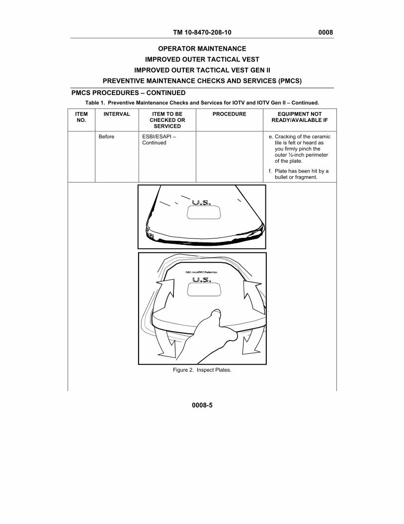
TM 10-8470-208-10 0008
OPERATOR MAINTENANCE IMPROVED OUTER TACTICAL VEST
IMPROVED OUTER TACTICAL VEST GEN II PREVENTIVE MAINTENANCE CHECKS AND SERVICES (PMCS)
PMCS PROCEDURES – CONTINUED Table 1. Preventive Maintenance Checks and Services for IOTV and IOTV Gen II – Continued.
0008-5
ITEM NO.
INTERVAL ITEM TO BE CHECKED OR
SERVICED
PROCEDURE EQUIPMENT NOT READY/AVAILABLE IF
Before ESBI/ESAPI – Continued
e. Cracking of the ceramic tile is felt or heard as you firmly pinch the outer ½-inch perimeter of the plate.
f. Plate has been hit by a bullet or fragment.
Figure 2. Inspect Plates.
TM 10-8470-208-10 0008
OPERATOR MAINTENANCE IMPROVED OUTER TACTICAL VEST
IMPROVED OUTER TACTICAL VEST GEN II PREVENTIVE MAINTENANCE CHECKS AND SERVICES (PMCS)
PMCS PROCEDURES – CONTINUED Table 1. Preventive Maintenance Checks and Services for IOTV and IOTV Gen II – Continued.
0008-6
ITEM NO.
INTERVAL ITEM TO BE CHECKED OR
SERVICED
PROCEDURE EQUIPMENT NOT READY/AVAILABLE IF
3 Before IOTV or IOTV Gen II Vest
Soldier Don the IOTV
a. Slip over head if the left shoulder is connected, or slide onto shoulders from right side if left shoulder strap is separated.
b. To connect left shoulder straps, sandwich hook and loop fastener strap on front carrier between the two hook and loop fastener straps on back carrier.
c. Secure snap fastener.
d. Cover the buckle by folding over fabric flaps on carrier and securing hook and loop fastener.
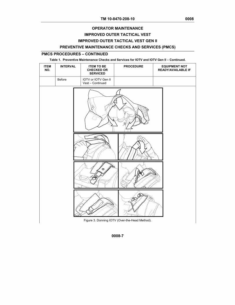
TM 10-8470-208-10 0008
OPERATOR MAINTENANCE IMPROVED OUTER TACTICAL VEST
IMPROVED OUTER TACTICAL VEST GEN II PREVENTIVE MAINTENANCE CHECKS AND SERVICES (PMCS)
PMCS PROCEDURES – CONTINUED Table 1. Preventive Maintenance Checks and Services for IOTV and IOTV Gen II – Continued.
0008-7
ITEM NO.
INTERVAL ITEM TO BE CHECKED OR
SERVICED
PROCEDURE EQUIPMENT NOT READY/AVAILABLE IF
Before IOTV or IOTV Gen II Vest – Continued
Figure 3. Donning IOTV (Over-the-Head Method).
TM 10-8470-208-10 0008
OPERATOR MAINTENANCE IMPROVED OUTER TACTICAL VEST
IMPROVED OUTER TACTICAL VEST GEN II PREVENTIVE MAINTENANCE CHECKS AND SERVICES (PMCS)
PMCS PROCEDURES – CONTINUED Table 1. Preventive Maintenance Checks and Services for IOTV and IOTV Gen II – Continued.
0008-8
ITEM NO.
INTERVAL ITEM TO BE CHECKED OR
SERVICED
PROCEDURE EQUIPMENT NOT READY/AVAILABLE IF
Before IOTV or IOTV Gen II Vest – Continued
e. Secure internal elastic band by lifting front carrier and pulling two halves of the elastic band forward and connecting hook and loop fasteners (Figure 4).
f. With the front carrier down, lift up the front flap to reveal the side plate carrier attachment points (Figure 5).
g. Pull on of the side plate carriers around the body and attach to same side hook and loop fastener in front. Repeat with other side.
h. Close the front flap, securing with hook and loop fasteners, and tuck the bottom of the front flap up into the front flap pocket.
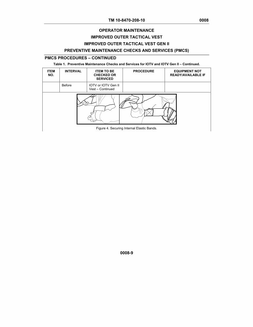
TM 10-8470-208-10 0008
OPERATOR MAINTENANCE IMPROVED OUTER TACTICAL VEST
IMPROVED OUTER TACTICAL VEST GEN II PREVENTIVE MAINTENANCE CHECKS AND SERVICES (PMCS)
PMCS PROCEDURES – CONTINUED Table 1. Preventive Maintenance Checks and Services for IOTV and IOTV Gen II – Continued.
0008-9
ITEM NO.
INTERVAL ITEM TO BE CHECKED OR
SERVICED
PROCEDURE EQUIPMENT NOT READY/AVAILABLE IF
Before IOTV or IOTV Gen II Vest – Continued
Figure 4. Securing Internal Elastic Bands.

TM 10-8470-208-10 0008
OPERATOR MAINTENANCE IMPROVED OUTER TACTICAL VEST
IMPROVED OUTER TACTICAL VEST GEN II PREVENTIVE MAINTENANCE CHECKS AND SERVICES (PMCS)
PMCS PROCEDURES – CONTINUED Table 1. Preventive Maintenance Checks and Services for IOTV and IOTV Gen II – Continued.
0008-10
ITEM NO.
INTERVAL ITEM TO BE CHECKED OR
SERVICED
PROCEDURE EQUIPMENT NOT READY/AVAILABLE IF
Before IOTV or IOTV Gen II Vest – Continued
Figure 5. Securing Side Plate Carriers.
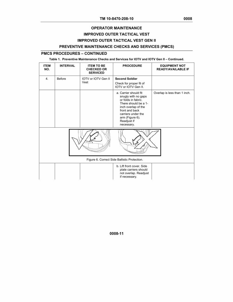
TM 10-8470-208-10 0008
OPERATOR MAINTENANCE IMPROVED OUTER TACTICAL VEST
IMPROVED OUTER TACTICAL VEST GEN II PREVENTIVE MAINTENANCE CHECKS AND SERVICES (PMCS)
PMCS PROCEDURES – CONTINUED Table 1. Preventive Maintenance Checks and Services for IOTV and IOTV Gen II – Continued.
0008-11
ITEM NO.
INTERVAL ITEM TO BE CHECKED OR
SERVICED
PROCEDURE EQUIPMENT NOT READY/AVAILABLE IF
4. Before IOTV or IOTV Gen II Vest
Second Soldier Check for proper fit of IOTV or IOTV Gen II.
a. Carrier should fit snugly with no gaps or folds in fabric. There should be a 1-inch overlap of the front and back carriers under the arm (Figure 6). Readjust if necessary.
Overlap is less than 1 inch.
Figure 6. Correct Side Ballistic Protection.
b. Lift front cover. Side plate carriers should not overlap. Readjust if necessary.
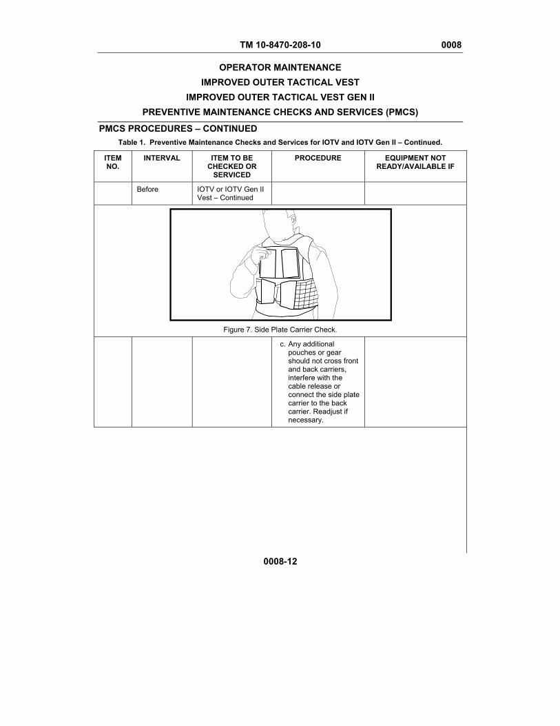
TM 10-8470-208-10 0008
OPERATOR MAINTENANCE IMPROVED OUTER TACTICAL VEST
IMPROVED OUTER TACTICAL VEST GEN II PREVENTIVE MAINTENANCE CHECKS AND SERVICES (PMCS)
PMCS PROCEDURES – CONTINUED Table 1. Preventive Maintenance Checks and Services for IOTV and IOTV Gen II – Continued.
0008-12
ITEM NO.
INTERVAL ITEM TO BE CHECKED OR
SERVICED
PROCEDURE EQUIPMENT NOT READY/AVAILABLE IF
Before IOTV or IOTV Gen II Vest – Continued
Figure 7. Side Plate Carrier Check.
c. Any additional pouches or gear should not cross front and back carriers, interfere with the cable release or connect the side plate carrier to the back carrier. Readjust if necessary.
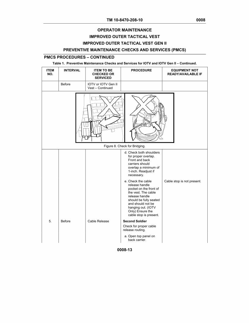
TM 10-8470-208-10 0008
OPERATOR MAINTENANCE IMPROVED OUTER TACTICAL VEST
IMPROVED OUTER TACTICAL VEST GEN II PREVENTIVE MAINTENANCE CHECKS AND SERVICES (PMCS)
PMCS PROCEDURES – CONTINUED Table 1. Preventive Maintenance Checks and Services for IOTV and IOTV Gen II – Continued.
0008-13
ITEM NO.
INTERVAL ITEM TO BE CHECKED OR
SERVICED
PROCEDURE EQUIPMENT NOT READY/AVAILABLE IF
Before IOTV or IOTV Gen II Vest – Continued
Figure 8. Check for Bridging.
d. Check both shoulders for proper overlap. Front and back carriers should overlap a minimum of 1-inch. Readjust if necessary.
e. Check the cable release handle pocket on the front of the vest. The cable release handle should be fully seated and should not be hanging out. (IOTV Only) Ensure the cable stop is present.
Cable stop is not present.
5. Before Cable Release Second Soldier Check for proper cable release routing.
a. Open top panel on back carrier.
TM 10-8470-208-10 0008
OPERATOR MAINTENANCE IMPROVED OUTER TACTICAL VEST
IMPROVED OUTER TACTICAL VEST GEN II PREVENTIVE MAINTENANCE CHECKS AND SERVICES (PMCS)
PMCS PROCEDURES – CONTINUED Table 1. Preventive Maintenance Checks and Services for IOTV and IOTV Gen II – Continued.
0008-14
ITEM NO.
INTERVAL ITEM TO BE CHECKED OR
SERVICED
PROCEDURE EQUIPMENT NOT READY/AVAILABLE IF
Before Cable Release – Continued
b. Ensure the long and short cables are not crossing and run freely through the vest. Readjust if necessary.
c. Ensure the cable routes through both webbing loops (Figure 10, Items 1 and 2). Readjust if necessary.
d. Ensure the cable extends at least 1 ½ inches past the left-most webbing loop (Figure 10, Item 1).
Cable is too short.
e. Ensure the cable is not taped, tied or otherwise secured to the IOTV and the Land Warrior webbing is not to secure the cable release. Remove any tape or ties.
f. Close top flap and open back flap.
g. Ensure all six straps from the side plate carriers and internal elastic bands are attached to the three pieces of center webbing.
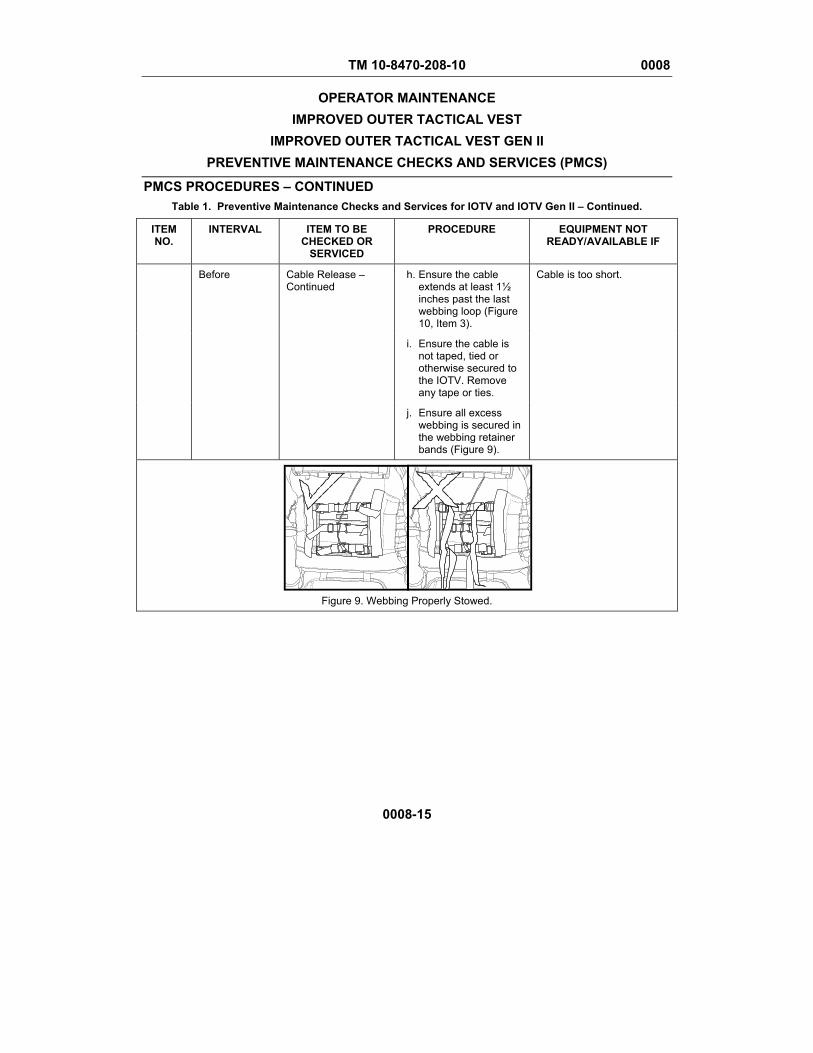
TM 10-8470-208-10 0008
OPERATOR MAINTENANCE IMPROVED OUTER TACTICAL VEST
IMPROVED OUTER TACTICAL VEST GEN II PREVENTIVE MAINTENANCE CHECKS AND SERVICES (PMCS)
PMCS PROCEDURES – CONTINUED Table 1. Preventive Maintenance Checks and Services for IOTV and IOTV Gen II – Continued.
0008-15
ITEM NO.
INTERVAL ITEM TO BE CHECKED OR
SERVICED
PROCEDURE EQUIPMENT NOT READY/AVAILABLE IF
Before Cable Release – Continued
h. Ensure the cable extends at least 1½ inches past the last webbing loop (Figure 10, Item 3).
Cable is too short.
i. Ensure the cable is not taped, tied or otherwise secured to the IOTV. Remove any tape or ties.
j. Ensure all excess webbing is secured in the webbing retainer bands (Figure 9).
Figure 9. Webbing Properly Stowed.
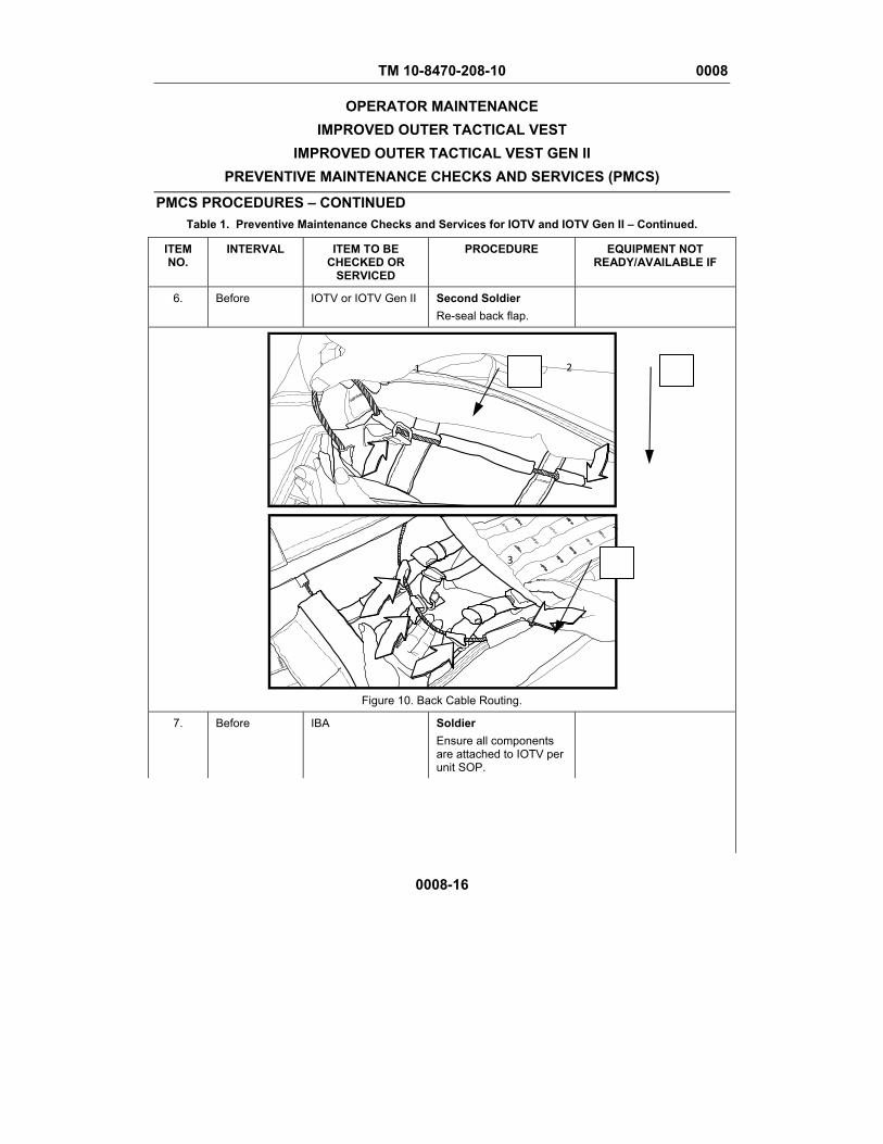
TM 10-8470-208-10 0008
OPERATOR MAINTENANCE IMPROVED OUTER TACTICAL VEST
IMPROVED OUTER TACTICAL VEST GEN II PREVENTIVE MAINTENANCE CHECKS AND SERVICES (PMCS)
PMCS PROCEDURES – CONTINUED Table 1. Preventive Maintenance Checks and Services for IOTV and IOTV Gen II – Continued.
0008-16
ITEM NO.
INTERVAL ITEM TO BE CHECKED OR
SERVICED
PROCEDURE EQUIPMENT NOT READY/AVAILABLE IF
6. Before IOTV or IOTV Gen II Second Soldier Re-seal back flap.
Figure 10. Back Cable Routing.
7. Before IBA Soldier Ensure all components are attached to IOTV per unit SOP.
1 2
3

TM 10-8470-208-10 0008
OPERATOR MAINTENANCE IMPROVED OUTER TACTICAL VEST
IMPROVED OUTER TACTICAL VEST GEN II PREVENTIVE MAINTENANCE CHECKS AND SERVICES (PMCS)
PMCS PROCEDURES – CONTINUED Table 1. Preventive Maintenance Checks and Services for IOTV and IOTV Gen II – Continued.
0008-17
ITEM NO.
INTERVAL ITEM TO BE CHECKED OR
SERVICED
PROCEDURE EQUIPMENT NOT READY/AVAILABLE IF
8. After IBA Soldier Doff IOTV.
a. Lift front flap and detach side plate carriers by separating hook and loop fastener tapes.
b. Lift front carrier and detach elastic band at hook and loop fasteners.
c. Either lift the IOTV over the head or separate the left shoulder strap and slide IOTV off the right shoulder.
9. After ESAPI/ESBI Soldier a. Inspect ESAPI/ESBI
plates. Turn in plates if:
Outer cover is damaged exposing the ceramic tile material.
Plate is cracked and you hear loose pieces rattling around when shaken.
Creaking or squeaking of ceramic tile heard when plate twisted by hand.
Composite backing is delaminating (backing material plies are separating).
After ESAPI/ESBI – Continued
Cracking of the ceramic tile is felt or heard as you firmly pinch the outer ½-inch perimeter of the plate.
Plate has been hit by a bullet or fragment.
TM 10-8470-208-10 0008
OPERATOR MAINTENANCE IMPROVED OUTER TACTICAL VEST
IMPROVED OUTER TACTICAL VEST GEN II PREVENTIVE MAINTENANCE CHECKS AND SERVICES (PMCS)
PMCS PROCEDURES – CONTINUED Table 1. Preventive Maintenance Checks and Services for IOTV and IOTV Gen II – Continued.
0008-18
ITEM NO.
INTERVAL ITEM TO BE CHECKED OR
SERVICED
PROCEDURE EQUIPMENT NOT READY/AVAILABLE IF
b. Clean your ESAPI/ESBI thoroughly before storing
c. Place the ESAPI/ESBI into the IOTV pockets in the same manner as when worn. This prevents loss of plates.
d. Store the IOTV system as flat as possible to avoid bunching of materials.
e. It is recommended that the system, when dry, be stored in a plastic bag to keep out dirt, dust and moisture
10. Monthly IBA Soldier Disassemble IOTV.
a. Remove SAPI/ESAPI plates from the front and back carriers, if installed (Figure 11).
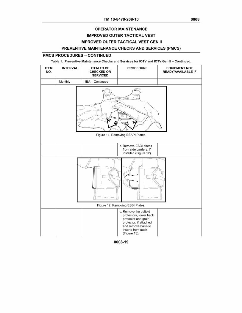
TM 10-8470-208-10 0008
OPERATOR MAINTENANCE IMPROVED OUTER TACTICAL VEST
IMPROVED OUTER TACTICAL VEST GEN II PREVENTIVE MAINTENANCE CHECKS AND SERVICES (PMCS)
PMCS PROCEDURES – CONTINUED Table 1. Preventive Maintenance Checks and Services for IOTV and IOTV Gen II – Continued.
0008-19
ITEM NO.
INTERVAL ITEM TO BE CHECKED OR
SERVICED
PROCEDURE EQUIPMENT NOT READY/AVAILABLE IF
Monthly IBA – Continued
Figure 11. Removing ESAPI Plates.
b. Remove ESBI plates from side carriers, if installed (Figure 12).
Figure 12. Removing ESBI Plates.
c. Remove the deltoid protectors, lower back protector and groin protector, if attached and remove ballistic inserts from each (Figure 13).
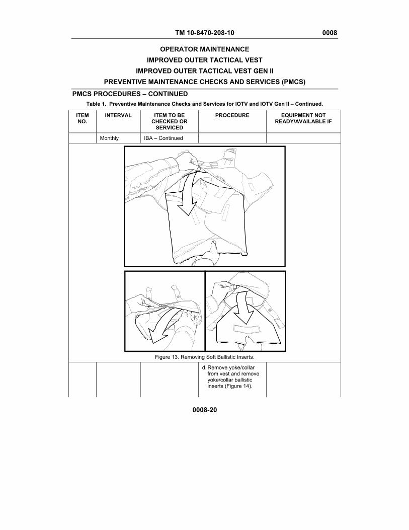
TM 10-8470-208-10 0008
OPERATOR MAINTENANCE IMPROVED OUTER TACTICAL VEST
IMPROVED OUTER TACTICAL VEST GEN II PREVENTIVE MAINTENANCE CHECKS AND SERVICES (PMCS)
PMCS PROCEDURES – CONTINUED Table 1. Preventive Maintenance Checks and Services for IOTV and IOTV Gen II – Continued.
0008-20
ITEM NO.
INTERVAL ITEM TO BE CHECKED OR
SERVICED
PROCEDURE EQUIPMENT NOT READY/AVAILABLE IF
Monthly IBA – Continued
Figure 13. Removing Soft Ballistic Inserts.
d. Remove yoke/collar from vest and remove yoke/collar ballistic inserts (Figure 14).
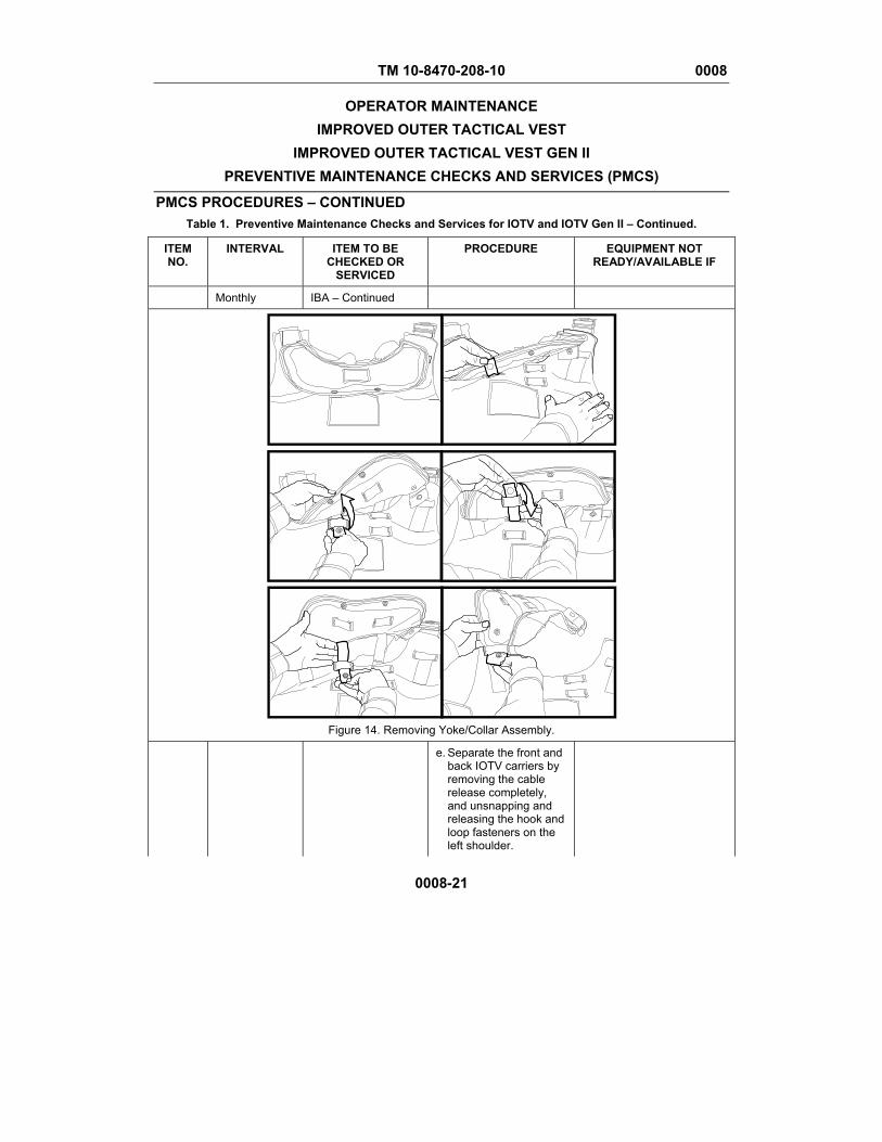
TM 10-8470-208-10 0008
OPERATOR MAINTENANCE IMPROVED OUTER TACTICAL VEST
IMPROVED OUTER TACTICAL VEST GEN II PREVENTIVE MAINTENANCE CHECKS AND SERVICES (PMCS)
PMCS PROCEDURES – CONTINUED Table 1. Preventive Maintenance Checks and Services for IOTV and IOTV Gen II – Continued.
0008-21
ITEM NO.
INTERVAL ITEM TO BE CHECKED OR
SERVICED
PROCEDURE EQUIPMENT NOT READY/AVAILABLE IF
Monthly IBA – Continued
Figure 14. Removing Yoke/Collar Assembly.
e. Separate the front and back IOTV carriers by removing the cable release completely, and unsnapping and releasing the hook and loop fasteners on the left shoulder.

TM 10-8470-208-10 0008
OPERATOR MAINTENANCE IMPROVED OUTER TACTICAL VEST
IMPROVED OUTER TACTICAL VEST GEN II PREVENTIVE MAINTENANCE CHECKS AND SERVICES (PMCS)
PMCS PROCEDURES – CONTINUED Table 1. Preventive Maintenance Checks and Services for IOTV and IOTV Gen II – Continued.
0008-22
ITEM NO.
INTERVAL ITEM TO BE CHECKED OR
SERVICED
PROCEDURE EQUIPMENT NOT READY/AVAILABLE IF
Monthly IBA – Continued f. Remove side plate carriers and internal elastic band.
g. Remove ballistic inserts from front and back carriers.
11. Monthly IBA Soldier Inventory the body armor.
a. Check the data label on each component to ensure each component is in the same size or size range (Figure 15 for IOTV, Figure 16 for IOTV Gen II).
Item sizes are mismatched.
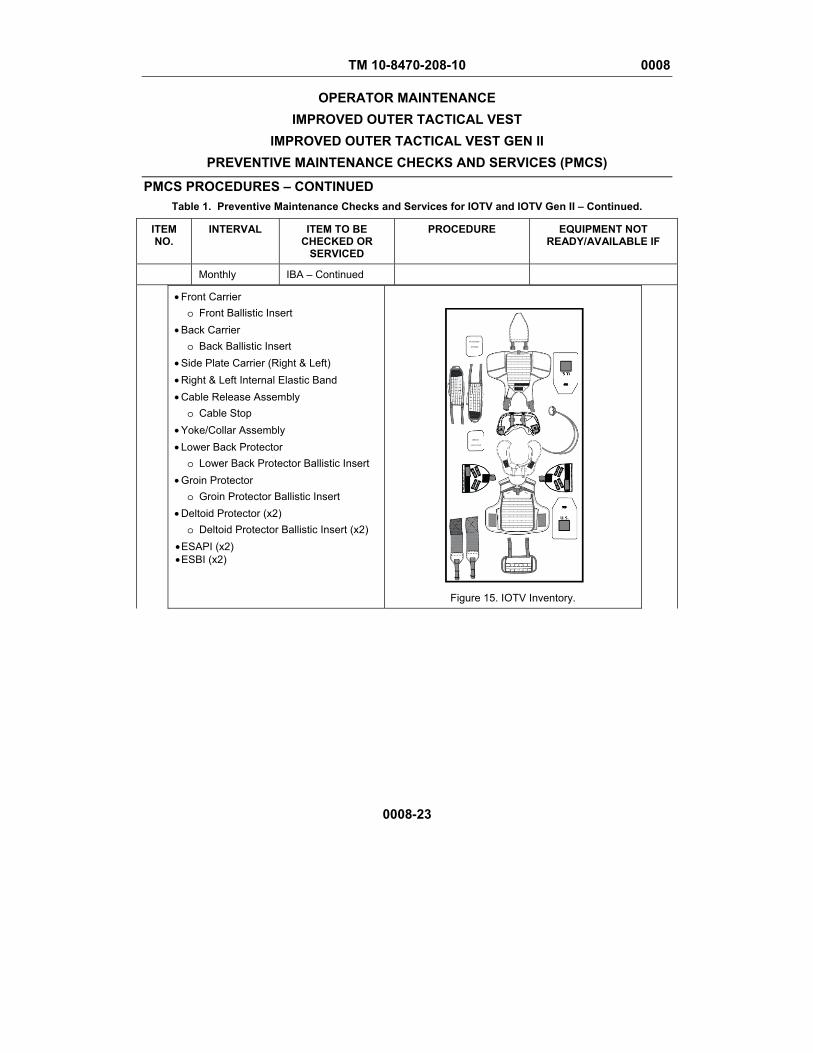
TM 10-8470-208-10 0008
OPERATOR MAINTENANCE IMPROVED OUTER TACTICAL VEST
IMPROVED OUTER TACTICAL VEST GEN II PREVENTIVE MAINTENANCE CHECKS AND SERVICES (PMCS)
PMCS PROCEDURES – CONTINUED Table 1. Preventive Maintenance Checks and Services for IOTV and IOTV Gen II – Continued.
0008-23
ITEM NO.
INTERVAL ITEM TO BE CHECKED OR
SERVICED
PROCEDURE EQUIPMENT NOT READY/AVAILABLE IF
Monthly IBA – Continued
• Front Carrier o Front Ballistic Insert
• Back Carrier o Back Ballistic Insert
• Side Plate Carrier (Right & Left) • Right & Left Internal Elastic Band • Cable Release Assembly
o Cable Stop • Yoke/Collar Assembly • Lower Back Protector
o Lower Back Protector Ballistic Insert • Groin Protector
o Groin Protector Ballistic Insert • Deltoid Protector (x2)
o Deltoid Protector Ballistic Insert (x2) • ESAPI (x2) • ESBI (x2)
Figure 15. IOTV Inventory.
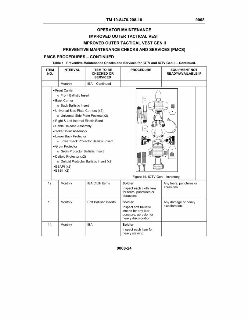
TM 10-8470-208-10 0008
OPERATOR MAINTENANCE IMPROVED OUTER TACTICAL VEST
IMPROVED OUTER TACTICAL VEST GEN II PREVENTIVE MAINTENANCE CHECKS AND SERVICES (PMCS)
PMCS PROCEDURES – CONTINUED Table 1. Preventive Maintenance Checks and Services for IOTV and IOTV Gen II – Continued.
0008-24
ITEM NO.
INTERVAL ITEM TO BE CHECKED OR
SERVICED
PROCEDURE EQUIPMENT NOT READY/AVAILABLE IF
Monthly IBA – Continued
• Front Carrier o Front Ballistic Insert
• Back Carrier o Back Ballistic Insert
• Universal Side Plate Carriers (x2) o Universal Side Plate Pockets(x2)
• Right & Left Internal Elastic Band • Cable Release Assembly • Yoke/Collar Assembly • Lower Back Protector
o Lower Back Protector Ballistic Insert • Groin Protector
o Groin Protector Ballistic Insert • Deltoid Protector (x2)
o Deltoid Protector Ballistic Insert (x2) • ESAPI (x2) • ESBI (x2)
Figure 16. IOTV Gen II Inventory.
12. Monthly IBA Cloth Items Soldier Inspect each cloth item for tears, punctures or abrasions.
Any tears, punctures or abrasions.
13. Monthly Soft Ballistic Inserts Soldier Inspect soft ballistic inserts for any tear, puncture, abrasion or heavy discoloration.
Any damage or heavy discoloration.
14. Monthly IBA Soldier Inspect each item for heavy staining.
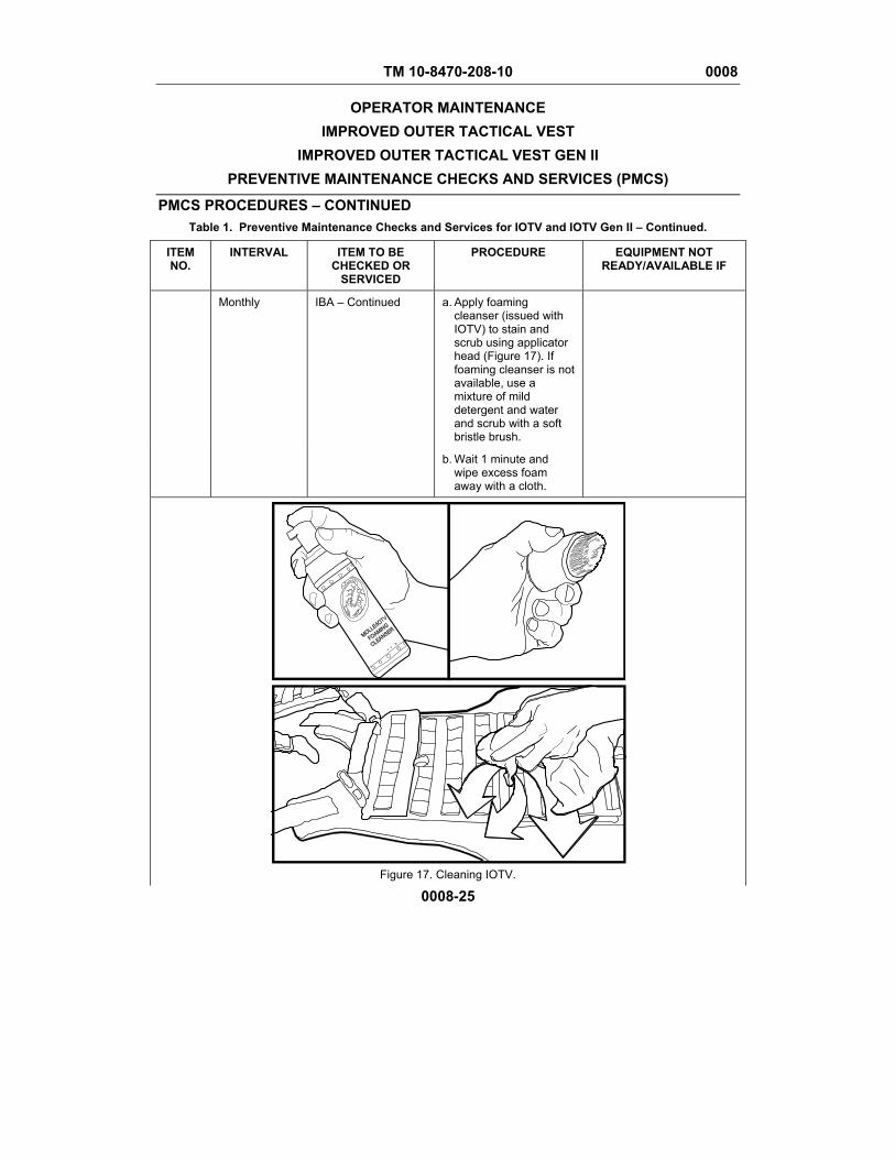
TM 10-8470-208-10 0008
OPERATOR MAINTENANCE IMPROVED OUTER TACTICAL VEST
IMPROVED OUTER TACTICAL VEST GEN II PREVENTIVE MAINTENANCE CHECKS AND SERVICES (PMCS)
PMCS PROCEDURES – CONTINUED Table 1. Preventive Maintenance Checks and Services for IOTV and IOTV Gen II – Continued.
0008-25
ITEM NO.
INTERVAL ITEM TO BE CHECKED OR
SERVICED
PROCEDURE EQUIPMENT NOT READY/AVAILABLE IF
Monthly IBA – Continued a. Apply foaming cleanser (issued with IOTV) to stain and scrub using applicator head (Figure 17). If foaming cleanser is not available, use a mixture of mild detergent and water and scrub with a soft bristle brush.
b. Wait 1 minute and wipe excess foam away with a cloth.
Figure 17. Cleaning IOTV.
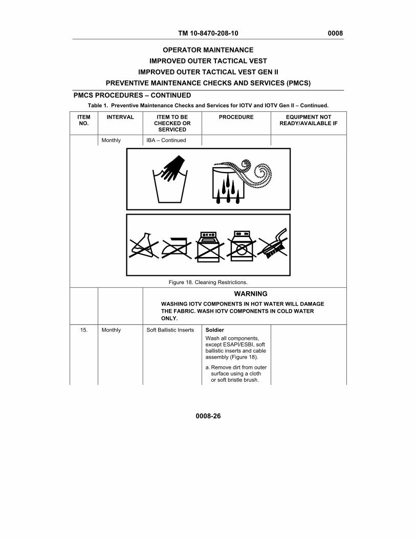
TM 10-8470-208-10 0008
OPERATOR MAINTENANCE IMPROVED OUTER TACTICAL VEST
IMPROVED OUTER TACTICAL VEST GEN II PREVENTIVE MAINTENANCE CHECKS AND SERVICES (PMCS)
PMCS PROCEDURES – CONTINUED Table 1. Preventive Maintenance Checks and Services for IOTV and IOTV Gen II – Continued.
0008-26
ITEM NO.
INTERVAL ITEM TO BE CHECKED OR
SERVICED
PROCEDURE EQUIPMENT NOT READY/AVAILABLE IF
Monthly IBA – Continued
Figure 18. Cleaning Restrictions.
WARNING
WASHING IOTV COMPONENTS IN HOT WATER WILL DAMAGE THE FABRIC. WASH IOTV COMPONENTS IN COLD WATER ONLY.
15. Monthly Soft Ballistic Inserts Soldier Wash all components, except ESAPI/ESBI, soft ballistic inserts and cable assembly (Figure 18).
a. Remove dirt from outer surface using a cloth or soft bristle brush.

TM 10-8470-208-10 0008
OPERATOR MAINTENANCE IMPROVED OUTER TACTICAL VEST
IMPROVED OUTER TACTICAL VEST GEN II PREVENTIVE MAINTENANCE CHECKS AND SERVICES (PMCS)
PMCS PROCEDURES – CONTINUED Table 1. Preventive Maintenance Checks and Services for IOTV and IOTV Gen II – Continued.
0008-27
ITEM NO.
INTERVAL ITEM TO BE CHECKED OR
SERVICED
PROCEDURE EQUIPMENT NOT READY/AVAILABLE IF
Monthly Soft Ballistic Inserts – Continued
b. Hand wash IOTV outer-shell and component carrier covers only in cold or warm water, with mild detergent or soap.
c. Air dry all components away from direct heat or sun.
16. Monthly ESAPI/ESBI Soldier Clean ESAPI/ESBI plates.
a. Remove loose dirt and lint from the outer surface of the ESAPI/ESBI using a cloth or soft bristle brush. Never use a stiff bristle brush.
b. Wet the ESAPI/ESBI in a sink or shower using warm, not hot, water.
c. Apply a mild soap or detergent to the soiled areas and scrub with a cloth or soft bristle brush. Scrub only long enough to remove soil.
d. Heavy grease/oil stains may be pre-spotted with a detergent mixture and scrubbed with a soft brush.
e. Rinse the ESAPI/ESBI with warm water until all suds are completely gone.
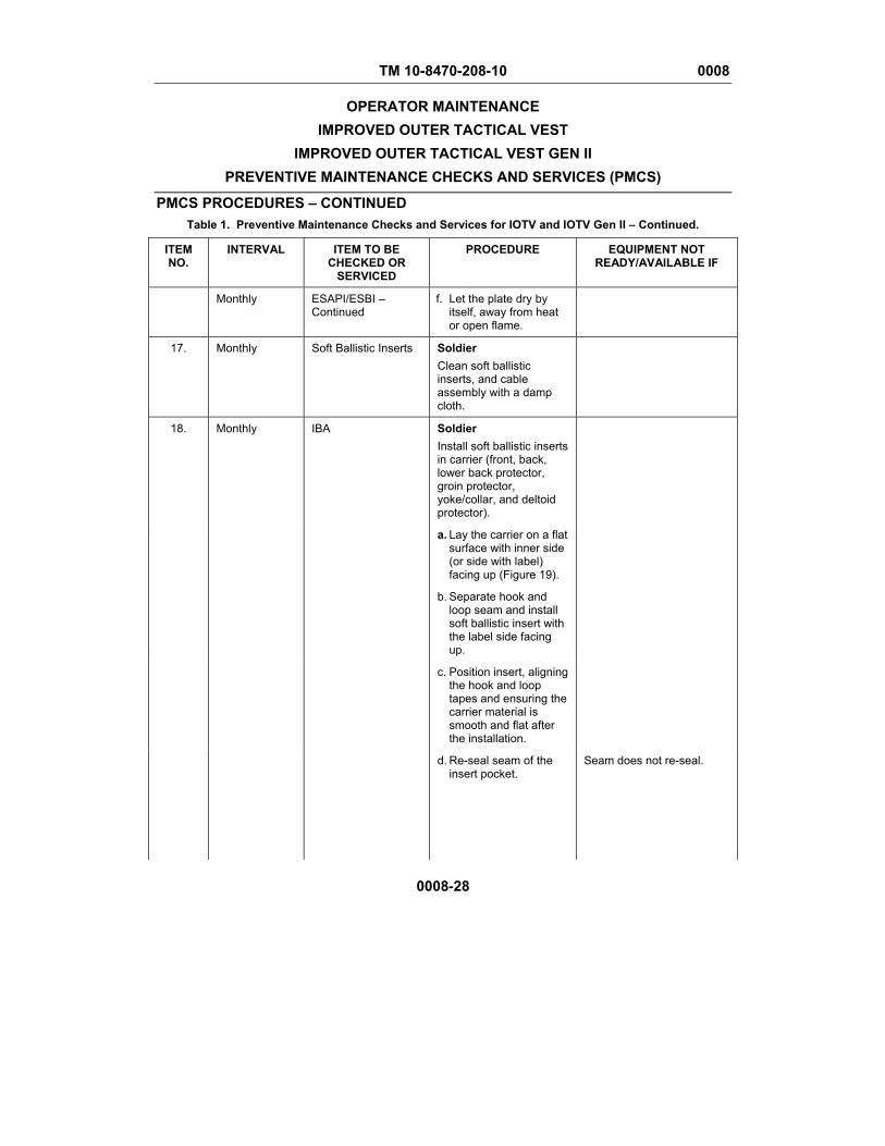
TM 10-8470-208-10 0008
OPERATOR MAINTENANCE IMPROVED OUTER TACTICAL VEST
IMPROVED OUTER TACTICAL VEST GEN II PREVENTIVE MAINTENANCE CHECKS AND SERVICES (PMCS)
PMCS PROCEDURES – CONTINUED Table 1. Preventive Maintenance Checks and Services for IOTV and IOTV Gen II – Continued.
0008-28
ITEM NO.
INTERVAL ITEM TO BE CHECKED OR
SERVICED
PROCEDURE EQUIPMENT NOT READY/AVAILABLE IF
Monthly ESAPI/ESBI – Continued
f. Let the plate dry by itself, away from heat or open flame.
17. Monthly Soft Ballistic Inserts Soldier Clean soft ballistic inserts, and cable assembly with a damp cloth.
18. Monthly IBA Soldier Install soft ballistic inserts in carrier (front, back, lower back protector, groin protector, yoke/collar, and deltoid protector).
a. Lay the carrier on a flat surface with inner side (or side with label) facing up (Figure 19).
b. Separate hook and loop seam and install soft ballistic insert with the label side facing up.
c. Position insert, aligning the hook and loop tapes and ensuring the carrier material is smooth and flat after the installation.
d. Re-seal seam of the insert pocket.
Seam does not re-seal.
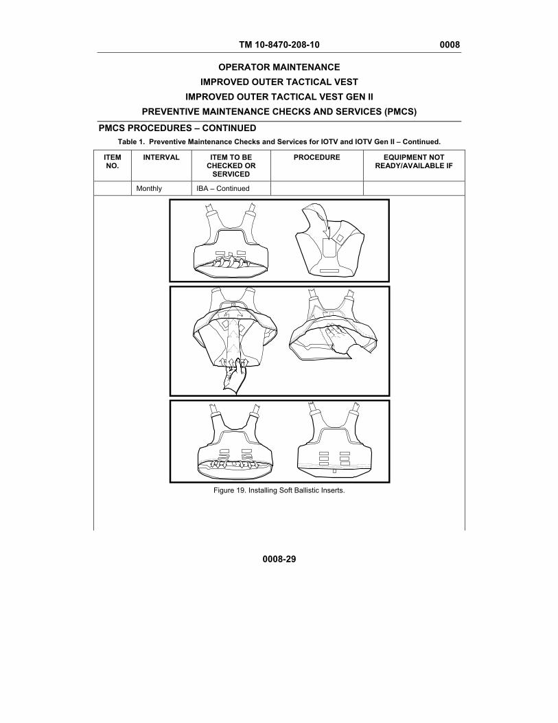
TM 10-8470-208-10 0008
OPERATOR MAINTENANCE IMPROVED OUTER TACTICAL VEST
IMPROVED OUTER TACTICAL VEST GEN II PREVENTIVE MAINTENANCE CHECKS AND SERVICES (PMCS)
PMCS PROCEDURES – CONTINUED Table 1. Preventive Maintenance Checks and Services for IOTV and IOTV Gen II – Continued.
0008-29
ITEM NO.
INTERVAL ITEM TO BE CHECKED OR
SERVICED
PROCEDURE EQUIPMENT NOT READY/AVAILABLE IF
Monthly IBA – Continued
Figure 19. Installing Soft Ballistic Inserts.

TM 10-8470-208-10 0008
OPERATOR MAINTENANCE IMPROVED OUTER TACTICAL VEST
IMPROVED OUTER TACTICAL VEST GEN II PREVENTIVE MAINTENANCE CHECKS AND SERVICES (PMCS)
PMCS PROCEDURES – CONTINUED Table 1. Preventive Maintenance Checks and Services for IOTV and IOTV Gen II – Continued.
0008-30
ITEM NO.
INTERVAL ITEM TO BE CHECKED OR
SERVICED
PROCEDURE EQUIPMENT NOT READY/AVAILABLE IF
19. Monthly Cable Release Assembly
Soldier Install cable release assembly.
a. (IOTV ONLY) Route the cables through the grommets on the cable stop. It does not matter which cable goes through which grommet.
b. Insert the cable through the cable release handle pocket and route through the right shoulder (Figure 20).
NOTE On the IOTV Gen II, the cable release routing channel is sewn as one piece throughout the front carrier. The second step in Figure 19 is only required for the IOTV.)
c. (IOTV ONLY) Continue to route cable through the release cable webbing channel on the right shoulder of the front carrier (Figure 20).
d. Stow the cable-release handle in the cable release handle pocket and secure with the hook and loop patches inside the pocket.
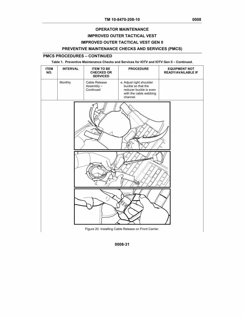
TM 10-8470-208-10 0008
OPERATOR MAINTENANCE IMPROVED OUTER TACTICAL VEST
IMPROVED OUTER TACTICAL VEST GEN II PREVENTIVE MAINTENANCE CHECKS AND SERVICES (PMCS)
PMCS PROCEDURES – CONTINUED Table 1. Preventive Maintenance Checks and Services for IOTV and IOTV Gen II – Continued.
0008-31
ITEM NO.
INTERVAL ITEM TO BE CHECKED OR
SERVICED
PROCEDURE EQUIPMENT NOT READY/AVAILABLE IF
Monthly Cable Release Assembly – Continued
e. Adjust right shoulder buckle so that the reducer buckle is even with the cable webbing channel.
Figure 20. Installing Cable Release on Front Carrier.

TM 10-8470-208-10 0008
OPERATOR MAINTENANCE IMPROVED OUTER TACTICAL VEST
IMPROVED OUTER TACTICAL VEST GEN II PREVENTIVE MAINTENANCE CHECKS AND SERVICES (PMCS)
PMCS PROCEDURES – CONTINUED Table 1. Preventive Maintenance Checks and Services for IOTV and IOTV Gen II – Continued.
0008-32
ITEM NO.
INTERVAL ITEM TO BE CHECKED OR
SERVICED
PROCEDURE EQUIPMENT NOT READY/AVAILABLE IF
20. Monthly Vest Soldier Assemble the front and back carriers.
a. Lay both back and front carriers on a flat surface with like shoulder together (right to right, left to left) (Figure 21).
b. Route the left shoulder of the front carrier into the left shoulder of the back carrier. Repeat for right side.
c. Open the upper access panel on the back carrier. The buckle from the front carrier shoulder straps should now be in the back carrier.
d. Route both lengths of the cable release through the opening at the top of the upper access panel.
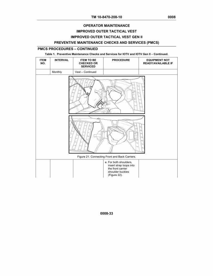
TM 10-8470-208-10 0008
OPERATOR MAINTENANCE IMPROVED OUTER TACTICAL VEST
IMPROVED OUTER TACTICAL VEST GEN II PREVENTIVE MAINTENANCE CHECKS AND SERVICES (PMCS)
PMCS PROCEDURES – CONTINUED Table 1. Preventive Maintenance Checks and Services for IOTV and IOTV Gen II – Continued.
0008-33
ITEM NO.
INTERVAL ITEM TO BE CHECKED OR
SERVICED
PROCEDURE EQUIPMENT NOT READY/AVAILABLE IF
Monthly Vest – Continued
Figure 21. Connecting Front and Back Carriers.
e. For both shoulders, insert strap loops into the front carrier shoulder buckles (Figure 22).
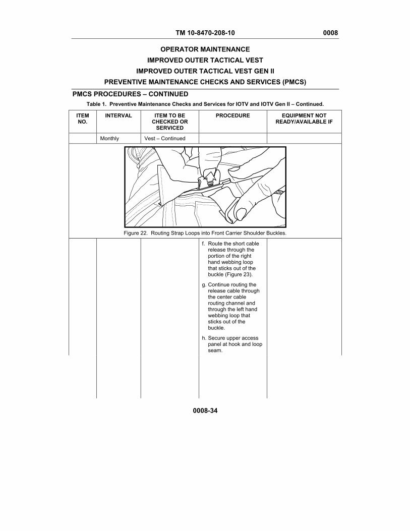
TM 10-8470-208-10 0008
OPERATOR MAINTENANCE IMPROVED OUTER TACTICAL VEST
IMPROVED OUTER TACTICAL VEST GEN II PREVENTIVE MAINTENANCE CHECKS AND SERVICES (PMCS)
PMCS PROCEDURES – CONTINUED Table 1. Preventive Maintenance Checks and Services for IOTV and IOTV Gen II – Continued.
0008-34
ITEM NO.
INTERVAL ITEM TO BE CHECKED OR
SERVICED
PROCEDURE EQUIPMENT NOT READY/AVAILABLE IF
Monthly Vest – Continued
Figure 22. Routing Strap Loops into Front Carrier Shoulder Buckles.
f. Route the short cable release through the portion of the right hand webbing loop that sticks out of the buckle (Figure 23).
g. Continue routing the release cable through the center cable routing channel and through the left hand webbing loop that sticks out of the buckle.
h. Secure upper access panel at hook and loop seam.
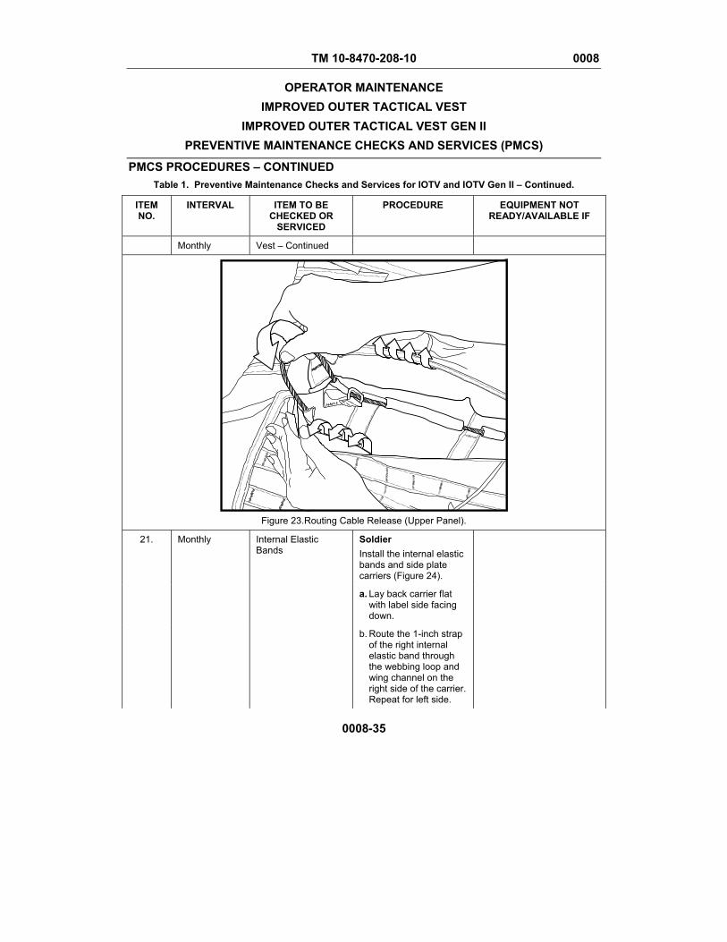
TM 10-8470-208-10 0008
OPERATOR MAINTENANCE IMPROVED OUTER TACTICAL VEST
IMPROVED OUTER TACTICAL VEST GEN II PREVENTIVE MAINTENANCE CHECKS AND SERVICES (PMCS)
PMCS PROCEDURES – CONTINUED Table 1. Preventive Maintenance Checks and Services for IOTV and IOTV Gen II – Continued.
0008-35
ITEM NO.
INTERVAL ITEM TO BE CHECKED OR
SERVICED
PROCEDURE EQUIPMENT NOT READY/AVAILABLE IF
Monthly Vest – Continued
Figure 23.Routing Cable Release (Upper Panel).
21. Monthly Internal Elastic Bands
Soldier Install the internal elastic bands and side plate carriers (Figure 24).
a. Lay back carrier flat with label side facing down.
b. Route the 1-inch strap of the right internal elastic band through the webbing loop and wing channel on the right side of the carrier. Repeat for left side.
TM 10-8470-208-10 0008
OPERATOR MAINTENANCE IMPROVED OUTER TACTICAL VEST
IMPROVED OUTER TACTICAL VEST GEN II PREVENTIVE MAINTENANCE CHECKS AND SERVICES (PMCS)
PMCS PROCEDURES – CONTINUED Table 1. Preventive Maintenance Checks and Services for IOTV and IOTV Gen II – Continued.
0008-36
ITEM NO.
INTERVAL ITEM TO BE CHECKED OR
SERVICED
PROCEDURE EQUIPMENT NOT READY/AVAILABLE IF
Monthly Internal Elastic Bands – Continued
c. Ensure the internal elastic bands are flat and the labels are facing down (toward the carrier). Route the free end of the 1-inch webbing on the right internal elastic band through the metal ring on the center webbing loop.
d. Route the end of the webbing back through the buckle leaving at least 2 inches of excess.
e. Route the right side plate carrier through the right wing channel, positioning the metal rings near the webbing loops. The label should be facing the carrier. Repeat for the left side.
f. Starting at the top center webbing loop, place the metal ring on the left side plate carrier over the top center webbing. Place the metal ring from the right side plate carrier over the center webbing.
g. Place the metal ring from the left internal elastic band over the middle webbing loop.

TM 10-8470-208-10 0008
OPERATOR MAINTENANCE IMPROVED OUTER TACTICAL VEST
IMPROVED OUTER TACTICAL VEST GEN II PREVENTIVE MAINTENANCE CHECKS AND SERVICES (PMCS)
PMCS PROCEDURES – CONTINUED Table 1. Preventive Maintenance Checks and Services for IOTV and IOTV Gen II – Continued.
0008-37
ITEM NO.
INTERVAL ITEM TO BE CHECKED OR
SERVICED
PROCEDURE EQUIPMENT NOT READY/AVAILABLE IF
Monthly Internal Elastic Bands – Continued
h. Place the metal ring from the left side plate carrier over the bottom center webbing. Place the metal ring from the right side plate carrier over the bottom center webbing.
i. Route the cable release through the center webbing loops from top to bottom.
j. Place end of release cable in the retention pocket.
k. Gather any loose straps and secure using elastic keepers.
l. Close back pocket and tuck the bottom of back flap up into the back flap pocket.
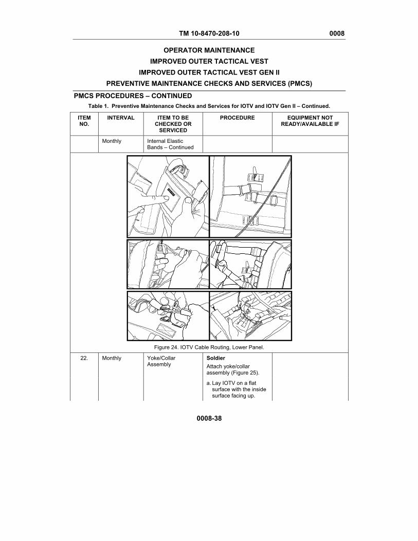
TM 10-8470-208-10 0008
OPERATOR MAINTENANCE IMPROVED OUTER TACTICAL VEST
IMPROVED OUTER TACTICAL VEST GEN II PREVENTIVE MAINTENANCE CHECKS AND SERVICES (PMCS)
PMCS PROCEDURES – CONTINUED Table 1. Preventive Maintenance Checks and Services for IOTV and IOTV Gen II – Continued.
0008-38
ITEM NO.
INTERVAL ITEM TO BE CHECKED OR
SERVICED
PROCEDURE EQUIPMENT NOT READY/AVAILABLE IF
Monthly Internal Elastic Bands – Continued
Figure 24. IOTV Cable Routing, Lower Panel.
22. Monthly Yoke/Collar Assembly
Soldier Attach yoke/collar assembly (Figure 25).
a. Lay IOTV on a flat surface with the inside surface facing up.

TM 10-8470-208-10 0008
OPERATOR MAINTENANCE IMPROVED OUTER TACTICAL VEST
IMPROVED OUTER TACTICAL VEST GEN II PREVENTIVE MAINTENANCE CHECKS AND SERVICES (PMCS)
PMCS PROCEDURES – CONTINUED Table 1. Preventive Maintenance Checks and Services for IOTV and IOTV Gen II – Continued.
0008-39
ITEM NO.
INTERVAL ITEM TO BE CHECKED OR
SERVICED
PROCEDURE EQUIPMENT NOT READY/AVAILABLE IF
Monthly Yoke/Collar Assembly – Continued
b. Position the yoke back collar on the back carrier with label facing up.
c. Attach back collar assembly to back carrier using standard MOLLE weave at both attachment points.
d. Mate hook and loop fasteners to complete attachment.
e. Position the front yoke on the front carrier with label facing up.
f. Route side straps on collar through mating loops on carrier and snap.
g. Use standard MOLLE weave to attach remaining straps to carrier.

TM 10-8470-208-10 0008
OPERATOR MAINTENANCE IMPROVED OUTER TACTICAL VEST
IMPROVED OUTER TACTICAL VEST GEN II PREVENTIVE MAINTENANCE CHECKS AND SERVICES (PMCS)
PMCS PROCEDURES – CONTINUED Table 1. Preventive Maintenance Checks and Services for IOTV and IOTV Gen II – Continued.
0008-40
ITEM NO.
INTERVAL ITEM TO BE CHECKED OR
SERVICED
PROCEDURE EQUIPMENT NOT READY/AVAILABLE IF
Monthly Yoke/Collar Assembly – Continued
Figure 25. Attaching Yoke/Collar Assembly.
TM 10-8470-208-10 0008
OPERATOR MAINTENANCE IMPROVED OUTER TACTICAL VEST
IMPROVED OUTER TACTICAL VEST GEN II PREVENTIVE MAINTENANCE CHECKS AND SERVICES (PMCS)
PMCS PROCEDURES – CONTINUED Table 1. Preventive Maintenance Checks and Services for IOTV and IOTV Gen II – Continued.
0008-41
ITEM NO.
INTERVAL ITEM TO BE CHECKED OR
SERVICED
PROCEDURE EQUIPMENT NOT READY/AVAILABLE IF
23. Monthly Groin and Lower Back Protectors
Soldier Install groin protector and lower back protector (as required) (Figure 26).
a. Lay carriers on flat surface with interior facing up.
b. Lay groin protector near bottom of front carrier with label facing up.
c. Route straps on groin protector through loops and snap.
d. Lay the lower back protector near the bottom of the back carrier with label facing up.
e. Route straps on lower back protector through loops and snap.
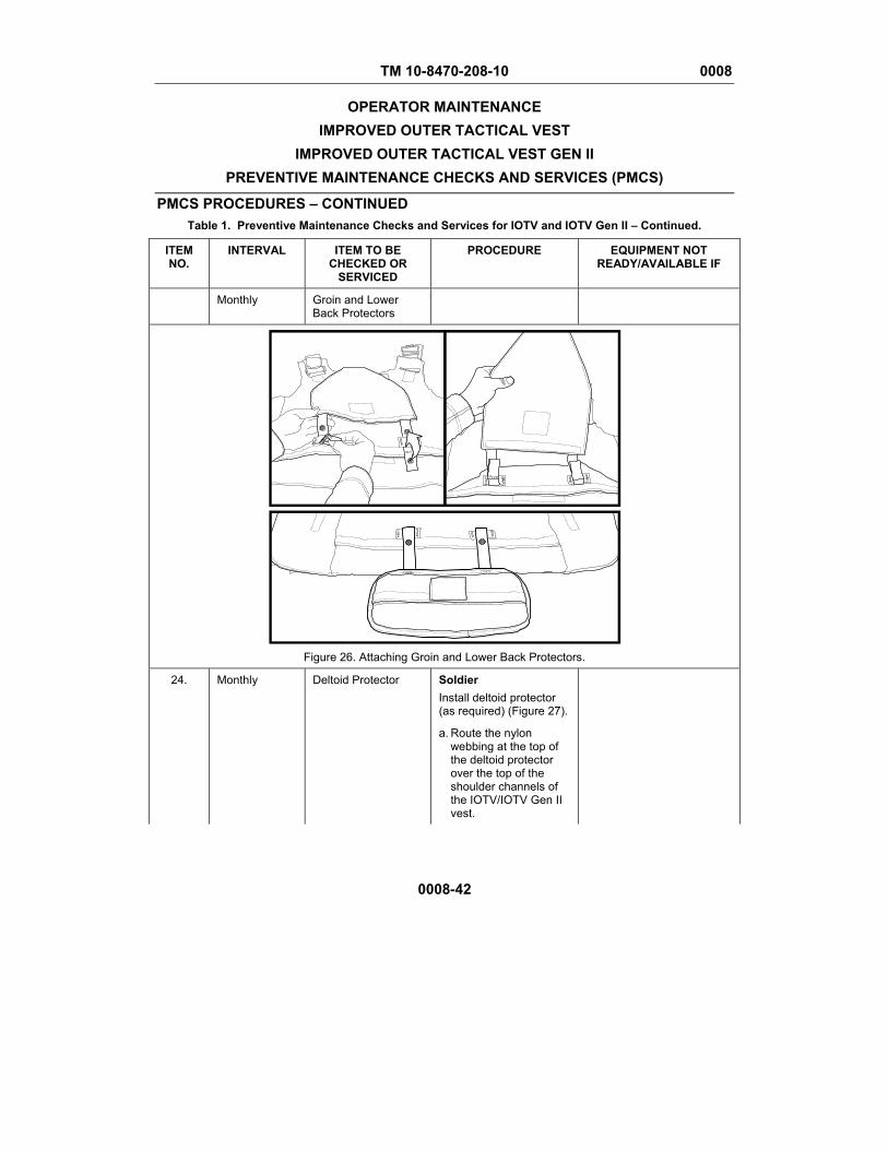
TM 10-8470-208-10 0008
OPERATOR MAINTENANCE IMPROVED OUTER TACTICAL VEST
IMPROVED OUTER TACTICAL VEST GEN II PREVENTIVE MAINTENANCE CHECKS AND SERVICES (PMCS)
PMCS PROCEDURES – CONTINUED Table 1. Preventive Maintenance Checks and Services for IOTV and IOTV Gen II – Continued.
0008-42
ITEM NO.
INTERVAL ITEM TO BE CHECKED OR
SERVICED
PROCEDURE EQUIPMENT NOT READY/AVAILABLE IF
Monthly Groin and Lower Back Protectors
Figure 26. Attaching Groin and Lower Back Protectors.
24. Monthly Deltoid Protector Soldier Install deltoid protector (as required) (Figure 27).
a. Route the nylon webbing at the top of the deltoid protector over the top of the shoulder channels of the IOTV/IOTV Gen II vest.
TM 10-8470-208-10 0008
OPERATOR MAINTENANCE IMPROVED OUTER TACTICAL VEST
IMPROVED OUTER TACTICAL VEST GEN II PREVENTIVE MAINTENANCE CHECKS AND SERVICES (PMCS)
PMCS PROCEDURES – CONTINUED Table 1. Preventive Maintenance Checks and Services for IOTV and IOTV Gen II – Continued.
0008-43
ITEM NO.
INTERVAL ITEM TO BE CHECKED OR
SERVICED
PROCEDURE EQUIPMENT NOT READY/AVAILABLE IF
Monthly Deltoid Protector – Continued
b. Continue to route the webbing back underneath the shoulder channels but above the yoke/collar assembly (if installed).
c. Secure with hook and loop fasteners and repeat for other side.
d. Don vest. Deltoid protectors should be as high as possible without interfering with motion. Deltoid protectors should be centered on the arm.
e. Route bicep webbing through straps and snap. Deltoid protector should be above the crease of the elbow.
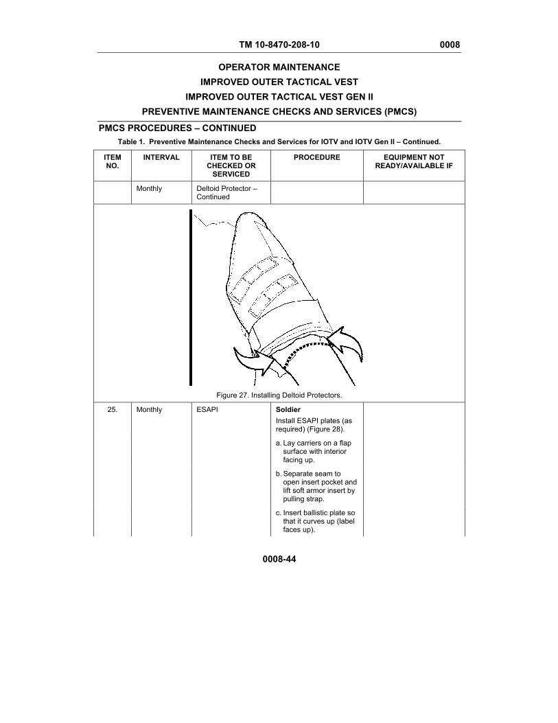
TM 10-8470-208-10 0008
OPERATOR MAINTENANCE IMPROVED OUTER TACTICAL VEST
IMPROVED OUTER TACTICAL VEST GEN II PREVENTIVE MAINTENANCE CHECKS AND SERVICES (PMCS)
PMCS PROCEDURES – CONTINUED Table 1. Preventive Maintenance Checks and Services for IOTV and IOTV Gen II – Continued.
0008-44
ITEM NO.
INTERVAL ITEM TO BE CHECKED OR
SERVICED
PROCEDURE EQUIPMENT NOT READY/AVAILABLE IF
Monthly Deltoid Protector – Continued
Figure 27. Installing Deltoid Protectors.
25. Monthly ESAPI Soldier Install ESAPI plates (as required) (Figure 28).
a. Lay carriers on a flap surface with interior facing up.
b. Separate seam to open insert pocket and lift soft armor insert by pulling strap.
c. Insert ballistic plate so that it curves up (label faces up).
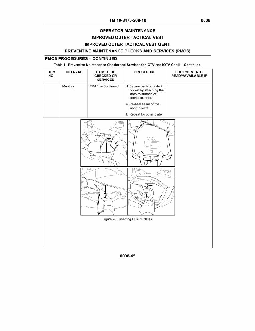
TM 10-8470-208-10 0008
OPERATOR MAINTENANCE IMPROVED OUTER TACTICAL VEST
IMPROVED OUTER TACTICAL VEST GEN II PREVENTIVE MAINTENANCE CHECKS AND SERVICES (PMCS)
PMCS PROCEDURES – CONTINUED Table 1. Preventive Maintenance Checks and Services for IOTV and IOTV Gen II – Continued.
0008-45
ITEM NO.
INTERVAL ITEM TO BE CHECKED OR
SERVICED
PROCEDURE EQUIPMENT NOT READY/AVAILABLE IF
Monthly ESAPI – Continued d. Secure ballistic plate in pocket by attaching the strap to surface of pocket exterior.
e. Re-seal seam of the insert pocket.
f. Repeat for other plate.
Figure 28. Inserting ESAPI Plates.

TM 10-8470-208-10 0008
OPERATOR MAINTENANCE IMPROVED OUTER TACTICAL VEST
IMPROVED OUTER TACTICAL VEST GEN II PREVENTIVE MAINTENANCE CHECKS AND SERVICES (PMCS)
PMCS PROCEDURES – CONTINUED Table 1. Preventive Maintenance Checks and Services for IOTV and IOTV Gen II – Continued.
0008-46
ITEM NO.
INTERVAL ITEM TO BE CHECKED OR
SERVICED
PROCEDURE EQUIPMENT NOT READY/AVAILABLE IF
26. Monthly ESBI Soldier Install ESBI plates (as required) (Figure 29).
a. Lay back carrier on flap surface with the interior facing up and side plate carriers folded out, exposing the side plate pockets.
b. Unfasten hook and loop fasteners on top flap of side plate pocket and pull out flap.
c. Insert the side ballistic plate.
d. Fold flap back into pocket and reattach the hook and loop fastener tape.
e. If using X-Small ESAPI plates, insert into unbuckled bottom flap and into top flap. Buckle bottom flap closed, ensuring the nylon webbing is routed back through the buckle (from bottom to top).
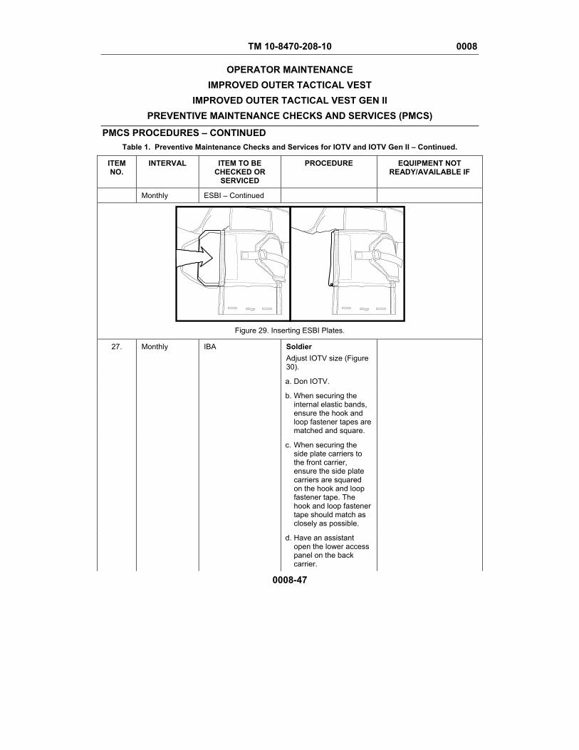
TM 10-8470-208-10 0008
OPERATOR MAINTENANCE IMPROVED OUTER TACTICAL VEST
IMPROVED OUTER TACTICAL VEST GEN II PREVENTIVE MAINTENANCE CHECKS AND SERVICES (PMCS)
PMCS PROCEDURES – CONTINUED Table 1. Preventive Maintenance Checks and Services for IOTV and IOTV Gen II – Continued.
0008-47
ITEM NO.
INTERVAL ITEM TO BE CHECKED OR
SERVICED
PROCEDURE EQUIPMENT NOT READY/AVAILABLE IF
Monthly ESBI – Continued
Figure 29. Inserting ESBI Plates.
27. Monthly IBA Soldier Adjust IOTV size (Figure 30).
a. Don IOTV.
b. When securing the internal elastic bands, ensure the hook and loop fastener tapes are matched and square.
c. When securing the side plate carriers to the front carrier, ensure the side plate carriers are squared on the hook and loop fastener tape. The hook and loop fastener tape should match as closely as possible.
d. Have an assistant open the lower access panel on the back carrier.
TM 10-8470-208-10 0008
OPERATOR MAINTENANCE IMPROVED OUTER TACTICAL VEST
IMPROVED OUTER TACTICAL VEST GEN II PREVENTIVE MAINTENANCE CHECKS AND SERVICES (PMCS)
PMCS PROCEDURES – CONTINUED Table 1. Preventive Maintenance Checks and Services for IOTV and IOTV Gen II – Continued.
0008-48
ITEM NO.
INTERVAL ITEM TO BE CHECKED OR
SERVICED
PROCEDURE EQUIPMENT NOT READY/AVAILABLE IF
Monthly IBA – Continued e. The assistant should tighten straps until the vest fits firmly and comfortably on the body. Ensure all straps are adjusted evenly. Start with the internal elastic bands and then adjust the side plate carriers.
f. Secure excess webbing in webbing keepers.
g. When completed, close the lower access panel and tuck the bottom up into the back flap pocket.
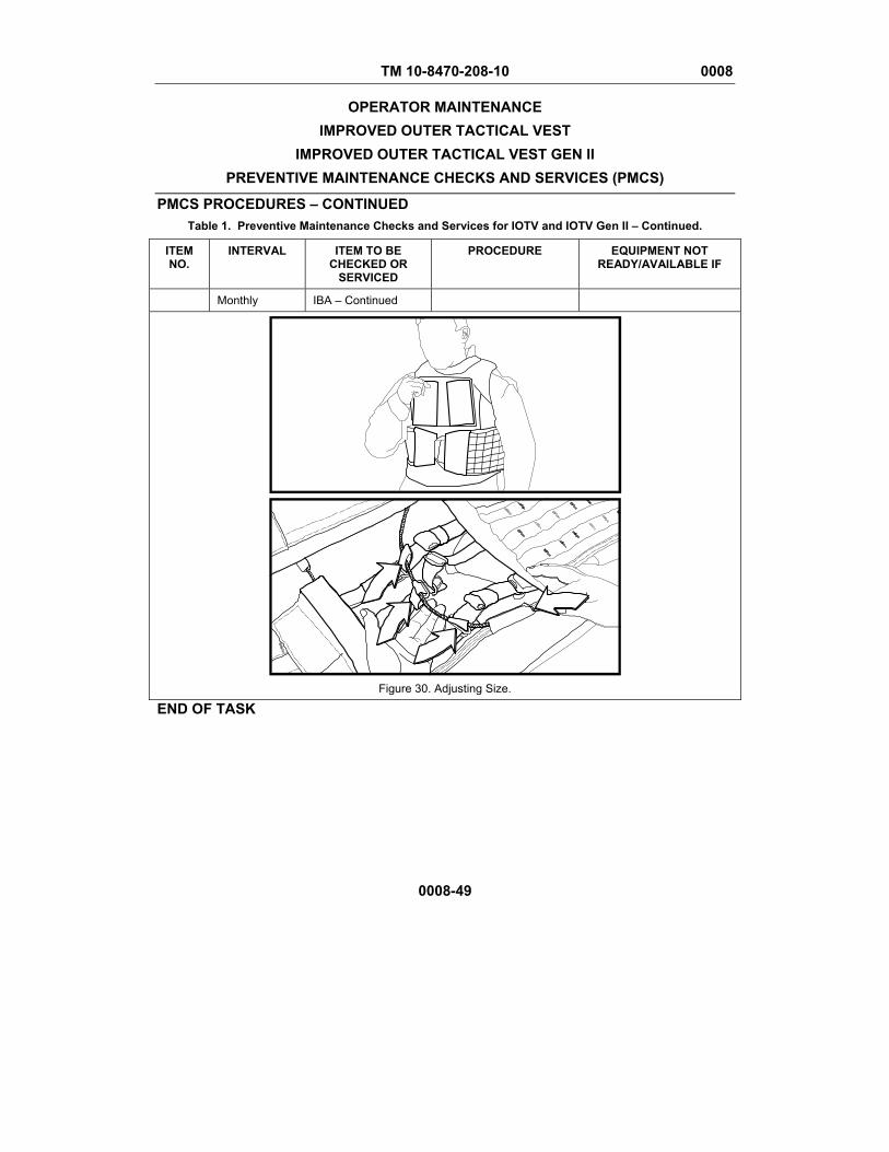
TM 10-8470-208-10 0008
OPERATOR MAINTENANCE IMPROVED OUTER TACTICAL VEST
IMPROVED OUTER TACTICAL VEST GEN II PREVENTIVE MAINTENANCE CHECKS AND SERVICES (PMCS)
PMCS PROCEDURES – CONTINUED Table 1. Preventive Maintenance Checks and Services for IOTV and IOTV Gen II – Continued.
0008-49
ITEM NO.
INTERVAL ITEM TO BE CHECKED OR
SERVICED
PROCEDURE EQUIPMENT NOT READY/AVAILABLE IF
Monthly IBA – Continued
Figure 30. Adjusting Size.
END OF TASK
TM 10-8470-208-10 0008
OPERATOR MAINTENANCE IMPROVED OUTER TACTICAL VEST
IMPROVED OUTER TACTICAL VEST GEN II PREVENTIVE MAINTENANCE CHECKS AND SERVICES (PMCS)
0008-50
MANDATORY REPLACEMENT PARTS
There are not mandatory replacement parts for the IOTV or IOTV Gen II.
END OF TASK
END OF WORK PACKAGE
TM 10-8470-208-10
CHAPTER 4
MAINTENANCE INSTRUCTIONS FOR
IMPROVED OUTER TACTICAL VEST (IOTV) AND
IMPROVED OUTER TACTICAL VEST GEN II (IOTV GEN II)

TM 10-8470-208-10 0009 OPERATOR MAINTENANCE
IMPROVED OUTER TACTICAL VEST IMPROVED OUTER TACTICAL VEST GEN II
PREPARATION FOR SHIPMENT AND STORAGE
0009-1/2 blank
INITIAL SETUP
N/A General Storage Requirements Administrative storage will be in accordance with the following: 1. Clean all items and ensure they are dry before IBA is placed in storage. Store each
individual IBA in a plastic bag to keep out dirt, dust and moisture. Placement of clothing items in administrative storage should be for short periods of time. Ensure all items are protected from pilferage, dampness, fire, dirt, and rodents.
2. Insert the ESAPI/ESBI into the IBA pockets in the same manner as when worn. This
prevents loss of components. Store the IBA system as flat as possible to avoid bunching of materials.
3. Items should be in mission readiness within 24 hours or within the time factors as
determined by the directing authority. 4. During the storage period, appropriate maintenance records will be kept. Before
placing equipment in administrative storage, current maintenance services and equipment serviceable criteria evaluations should be completed, shortcomings and deficiencies should be corrected, and all modification work orders should be applied.
5. Inside storage is preferred for items selected for administrative storage. If inside
storage is not available, trucks, vans, CONEX containers and other containers may be used.
In-Storage Inspection 1. Check that no damage or deterioration has occurred. 2. Check the adequacy of the storage facilities, efforts taken to control pests and
rodents, and protection against unfavorable climatic conditions and other elements that might cause damage to clothing items.
Shipment Requirements Ensure all items are protected from pilferage, dampness, fire, dirt, and rodents. END OF WORK PACKAGE


TM 10-8470-208-10 0010 OPERATOR MAINTENANCE
IMPROVED OUTER TACTICAL VEST IMPROVED OUTER TACTICAL VEST GEN II
SERVICE – CLEANING AND DRYING
0010-1
INITIAL SETUP
References: Materials/parts: WP 0015 Cleaning Foam System, Outer Vest (WP
0015, Item 1) GENERAL CLEANING INSTRUCTIONS
WARNING
Failure to follow all cleaning instructions could deteriorate damage or destroy the IBA, rendering it useless against ballistic treats.
To maintain your IBA so that it provides you with the maximum protection intended, it is extremely important to follow proper cleaning procedures. Do not bleach, machine wash, dry clean, or apply solvents, cleaning fluids, or yellow soap to any part of the IBA. They will discolor and/or deteriorate the IBA. Do not attempt to dye item or fix discolorations. IBA Vest and Components
WARNING
Do not machine wash or dry. Failure to follow these instructions may render your IBA useless against ballistic threats.
CAUTION
Do not use a stiff brush to clean any part of your IBA as this will damage the material.
1. Remove loose dirt and lint from the outer shell using a cloth or soft bristle brush.
Never use a stiff bristle brush.
2. Remove all soft ballistic inserts and the ESAPI/ESBI from the outer shell and component carriers
TM 10-8470-208-10 0010 OPERATOR MAINTENANCE
IMPROVED OUTER TACTICAL VEST IMPROVED OUTER TACTICAL VEST GEN II
SERVICE – CLEANING AND DRYING
0010-2
GENERAL CLEANING INSTRUCTIONS – CONTINUED
CAUTION
Never use bleach, yellow soap, cleaning fluids or solvents to clean the outer shell as this will stain and damage the material.
3. Hand-wash the outer shell and component carrier covers in cold or warm water, with
mild detergent or soap.
4. Badly soiled areas may be scrubbed. Scrub only long enough to remove soil.
5. Grease and oil stains may be pre-spotted with a mild detergent and water mixture, and scrubbed with a soft brush. If stubborn stain persists, repeat the procedure.
6. Rinse the outer shell and covers thoroughly in clean, warm water until suds are
completely gone. 7. Air-dry indoors or in shade, away from heat sources and direct sunlight. END OF TASK Soft Ballistic Inserts
WARNING
Do not machine wash or dry the soft ballistic inserts. Failure to follow these instructions may render the IBA useless against ballistic threats.
CAUTION
Do not intentionally submerge soft inserts in any liquid, including water. Do not use a stiff brush to clean any part of your IBA as this will damage the material.
Cleaning of the soft ballistics inserts is limited to removing loose dirt from the surface with a cloth or soft brush. If ballistic inserts become wet, allow to air dry in a flat position away from heat sources and direct sunlight. If ballistic insert becomes saturated with liquids such as gasoline, bleach or other lubricants, turn in for replacement as soon as possible. END OF TASK
TM 10-8470-208-10 0010 OPERATOR MAINTENANCE
IMPROVED OUTER TACTICAL VEST IMPROVED OUTER TACTICAL VEST GEN II
SERVICE – CLEANING AND DRYING
0010-3/4 blank
ESAPI/ESBI
WARNING
Do not machine wash or dry the ESAPI/ESBI inserts. Failure to follow these instructions may degrade the ESAPI/ESBI ballistic protection.
CAUTION
Do not submerge ESAPI/ESBI inserts in any liquid, including water. Do not use a stiff brush to clean any part of your IBA as this will damage the material.
1. Remove loose dirt and lint from the outer surface of the ESAPI/ESBI using a cloth or
soft bristle brush. Never use a stiff bristle brush.
2. Wet the ESAPI/ESBI in a sink or shower using warm, not hot, water. 3. Apply a mild soap or detergent to the soiled areas and scrub with a cloth or soft
bristle brush. 4. Badly soiled areas may be scrubbed with mild soap or detergent. 5. Scrub only long enough to remove soil. 6. Rinse the ESAPI/ESBI with warm water until all suds are completely gone. 7. Let the insert dry by itself, away from heat or open flame. END OF TASK END OF WORK PACKAGE

TM 10-8470-208-10 0011 OPERATOR MAINTENANCE
IMPROVED OUTER TACTICAL VEST IMPROVED OUTER TACTICAL VEST GEN II
ESAPI/ESBI INSERTS INSPECT, REPAIR
0011-1
INITIAL SETUP
References: Materials/parts: WP 0015 Tape, Pressure Sensitive Adhesive (WP
0015, Item 5) INSPECT
WARNING
Service members must ensure they have the correct protective inserts. The ESAPI and ESBI have green covers and provide a higher level of protection than the Small Arms Protective Insert (SAPI) which has a black cover. ESAPI should be worn by all personnel in-theater. If a service member has the older black SAPI plates, they should be turned in and replaced with green ESAPI plates. Failure to ensure the correct plate while conducting combat operations may result in injury or death.
Pre-combat Inspection The soldier must inspect the insert before each mission. The ESAPI/ESBI insert must be turned in if any of the following conditions are present:
• Outer Cover is damaged exposing the ceramic tile material.
• Plate is cracked and you hear loose pieces rattling around when shaken.
• Creaking or squeaking of ceramic tile heard when plate twisted by hand.
• Composite backing is delaminating (backing material plies are separating).
• Cracking of the ceramic tile is felt or heard as you firmly pinch the outer ½-inch perimeter of the plate.
• Plate has been hit by a bullet or fragment.
END OF TASK

TM 10-8470-208-10 0011 OPERATOR MAINTENANCE
IMPROVED OUTER TACTICAL VEST IMPROVED OUTER TACTICAL VEST GEN II
ESAPI/ESBI INSERTS INSPECT, REPAIR
0011-2
REPAIR
NOTE
Cloth backed adhesive tape is often referred to as duct tape, rigger’s tape or 100 mile-per-hour tape.
Interim repairs of the ESAPI/ESBI outer cover can be made using cloth backed adhesive tape until it can be exchanged. This repair does help to prevent the spread of existing delamination. It is not meant as a permanent fix. END OF TASK END OF WORK PACKAGE

TM 10-8470-208-10 0012 OPERATOR MAINTENANCE
IMPROVED OUTER TACTICAL VEST IMPROVED OUTER TACTICAL VEST GEN II
FABRIC REPAIR
0012-1
INITIAL SETUP
References: Materials/parts: WP 0015 Kit, Sewing (WP 0015, Item 2) Tape, Pressure Sensitive Adhesive (WP
0015, Item 5)
REPAIR
WARNING
Fabric repair in this work package does not apply to the fabric on the soft ballistic inserts. Any damage to the soft ballistic inserts is cause for turn-in. Failure to follow these instructions could result in degraded ballistic protection.
This work package provides instructions for repairing the fabric of the IBA. Outer Shell 1. To mend a ripped seam, overlap the two-edge and sew with straight and small stitches.
Figure 1. Straight Stitch. 2. To repair a tear, place the two edges together on the inside, and sew together.
Figure 2. Edge Sew.
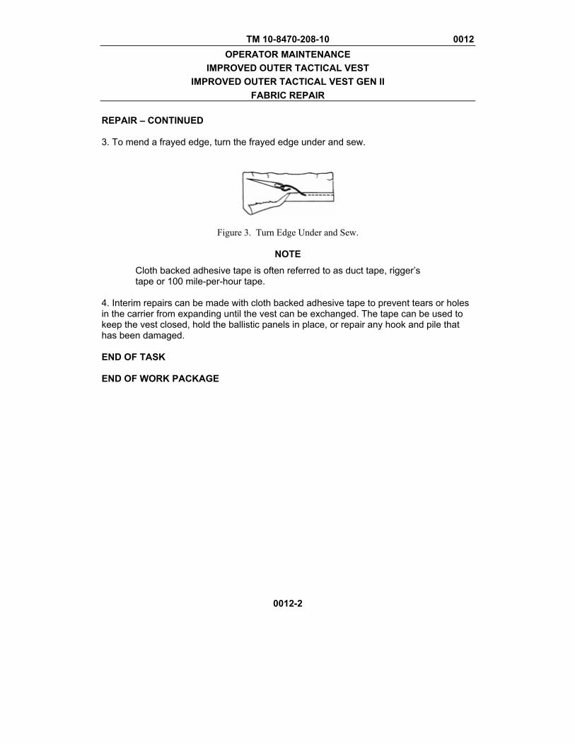
TM 10-8470-208-10 0012 OPERATOR MAINTENANCE
IMPROVED OUTER TACTICAL VEST IMPROVED OUTER TACTICAL VEST GEN II
FABRIC REPAIR
0012-2
REPAIR – CONTINUED 3. To mend a frayed edge, turn the frayed edge under and sew.
Figure 3. Turn Edge Under and Sew.
NOTE
Cloth backed adhesive tape is often referred to as duct tape, rigger’s tape or 100 mile-per-hour tape.
4. Interim repairs can be made with cloth backed adhesive tape to prevent tears or holes in the carrier from expanding until the vest can be exchanged. The tape can be used to keep the vest closed, hold the ballistic panels in place, or repair any hook and pile that has been damaged. END OF TASK END OF WORK PACKAGE
TM 10-8470-208-10
CHAPTER 5
SUPPORTING INFORMATION FOR
IMPROVED OUTER TACTICAL VEST (IOTV) AND
IMPROVED OUTER TACTICAL VEST (IOTV GEN II)

TM 10-8470-208-10 0013 OPERATOR MAINTENANCE
IMPROVED OUTER TACTICAL VEST IMPROVED OUTER TACTICAL VEST GEN II
REFERENCES
0013-1/2 blank
SCOPE This work package lists related field manuals, forms, technical manuals, and miscellaneous publications. MISCELLANEOUS PUBS/FORMS AR 700-138 Army Logistics Readiness and
Sustainability
CTA 50-970 Expendable/Durable Items (Except Medical, Class V Repair Parts, and Heraldic Items)
CTA 50-909 Field and Garrison Furnishings and Equipments
CTA 8-100 Army Medical Department Expendable/Durable Items
DA Form 2028 Recommended Changes to Publications and Blank Forms
DA PAM 750-8 The Army Maintenance Management System (TAMMS) Users Manual
FM 3-11.2 Multiservice Tactics, Techniques, and Procedures for Chemical, Biological, and Nuclear Contamination Avoidance
FM 4-25.11 First Aid Information SF 368 Product Quality Deficiency Report
END OF WORK PACKAGE

TM 10-8470-208-10 0014 OPERATOR MAINTENANCE
IMPROVED OUTER TACTICAL VEST IMPROVED OUTER TACTICAL VEST GEN II
COMPONENTS OF END ITEM (COEI) AND BASIC ISSUE ITEM (BII) LISTS
0014-1
COMPONENTS OF END ITEM (COEI) AND BASIC ISSUE ITEM (BII) LISTS INTRODUCTION SCOPE This work package lists COEI and BII for the Improved Outer Tactical Vest (IOTV) and Improved Outer Tactical Vest Gen II (IOTV Gen II) to help you inventory items for safe and efficient operation of the equipment. GENERAL The COEI and BII information is divided into the following lists: Components of End Item (COEI). This list is for information purposes only and is not authority to requisition replacements. These items are part of the IBA. As part of the end item, these items must be with the end item whenever it is issued or transferred between property accounts. Items of COEI are removed and separately packaged for transportation or shipment only when necessary. Illustrations are furnished to help you find and identify the items. Basic Issue Items (BII). These essential items are required to place the IBA in operation, operate it and to do emergency repairs. Although shipped separately packaged, BII must be with the IBA during operation and when it is transferred between property accounts. Listing these items is your authority to request/requisition them for replacement based on authorization of the end item by the TOE/MTOE. Illustrations are furnished to help you find and identify the items. EXPLANATION OF COLUMNS IN THE COEI LIST AND BII LIST Column (1) Item Number. Gives you the number of the item listed. Column (2) National Stock Number (NSN) and illustration. Identifies the stock number of the item to be used for requisitioning purposes and provides an illustration of the item. Column (3) Description, Part Number/(CAGEC). Identifies the Federal item name (in all capital letters) followed by a minimum description when needed. The stowage location of COEI and BII is also included in this column. The last line below the description is the part number and the Commercial and Government Entity Code (CAGEC) (in parentheses). Column (4) Usable On Code. When applicable, gives you a code if the item you need is not the same for different models of equipment.
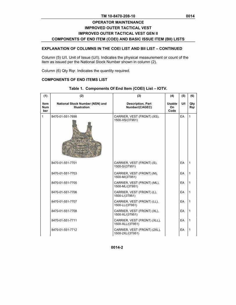
TM 10-8470-208-10 0014 OPERATOR MAINTENANCE
IMPROVED OUTER TACTICAL VEST IMPROVED OUTER TACTICAL VEST GEN II
COMPONENTS OF END ITEM (COEI) AND BASIC ISSUE ITEM (BII) LISTS
0014-2
EXPLANATION OF COLUMNS IN THE COEI LIST AND BII LIST – CONTINUED Column (5) U/I. Unit of Issue (U/I). Indicates the physical measurement or count of the item as issued per the National Stock Number shown in column (2). Column (6) Qty Rqr. Indicates the quantity required. COMPONENTS OF END ITEMS LIST
Table 1. Components Of End Item (COEI) List – IOTV.
(1)
Item Number
(2)
National Stock Number (NSN) and Illustration
(3)
Description, Part Number/(CAGEC)
(4)
Usable On
Code
(5)
U/I
(6)
QtyRqr
1 8470-01-551-7698
CARRIER, VEST (FRONT) (XS), 1500-XS/(3T951)
EA 1
8470-01-551-7701
CARRIER, VEST (FRONT) (S), 1500-S/(3T951)
EA 1
8470-01-551-7703 CARRIER, VEST (FRONT) (M), 1500-M/(3T951)
EA 1
8470-01-551-7705 CARRIER, VEST (FRONT) (ML), 1500-ML/(3T951)
EA 1
8470-01-551-7706 CARRIER, VEST (FRONT) (L), 1500-L/(3T951)
EA 1
8470-01-551-7707 CARRIER, VEST (FRONT) (LL), 1500-LL/(3T951)
EA 1
8470-01-551-7708 CARRIER, VEST (FRONT) (XL), 1500-XL/(3T951)
EA 1
8470-01-551-7711 CARRIER, VEST (FRONT) (XLL), 1500-XLL/(3T951)
EA 1
8470-01-551-7712 CARRIER, VEST (FRONT) (2XL), 1500-2XL/(3T951)
EA 1
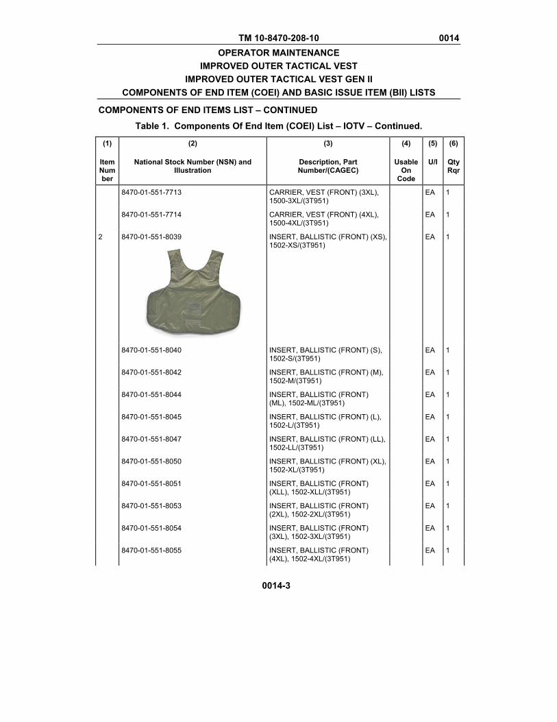
TM 10-8470-208-10 0014 OPERATOR MAINTENANCE
IMPROVED OUTER TACTICAL VEST IMPROVED OUTER TACTICAL VEST GEN II
COMPONENTS OF END ITEM (COEI) AND BASIC ISSUE ITEM (BII) LISTS
COMPONENTS OF END ITEMS LIST – CONTINUED
Table 1. Components Of End Item (COEI) List – IOTV – Continued.
0014-3
(1)
Item Number
(2)
National Stock Number (NSN) and Illustration
(3)
Description, Part Number/(CAGEC)
(4)
Usable On
Code
(5)
U/I
(6)
QtyRqr
8470-01-551-7713 CARRIER, VEST (FRONT) (3XL), 1500-3XL/(3T951)
EA 1
8470-01-551-7714 CARRIER, VEST (FRONT) (4XL), 1500-4XL/(3T951)
EA 1
2 8470-01-551-8039
INSERT, BALLISTIC (FRONT) (XS), 1502-XS/(3T951)
EA 1
8470-01-551-8040 INSERT, BALLISTIC (FRONT) (S), 1502-S/(3T951)
EA 1
8470-01-551-8042 INSERT, BALLISTIC (FRONT) (M), 1502-M/(3T951)
EA 1
8470-01-551-8044 INSERT, BALLISTIC (FRONT) (ML), 1502-ML/(3T951)
EA 1
8470-01-551-8045 INSERT, BALLISTIC (FRONT) (L), 1502-L/(3T951)
EA 1
8470-01-551-8047 INSERT, BALLISTIC (FRONT) (LL), 1502-LL/(3T951)
EA 1
8470-01-551-8050 INSERT, BALLISTIC (FRONT) (XL), 1502-XL/(3T951)
EA 1
8470-01-551-8051 INSERT, BALLISTIC (FRONT) (XLL), 1502-XLL/(3T951)
EA 1
8470-01-551-8053 INSERT, BALLISTIC (FRONT) (2XL), 1502-2XL/(3T951)
EA 1
8470-01-551-8054 INSERT, BALLISTIC (FRONT) (3XL), 1502-3XL/(3T951)
EA 1
8470-01-551-8055 INSERT, BALLISTIC (FRONT) (4XL), 1502-4XL/(3T951)
EA 1
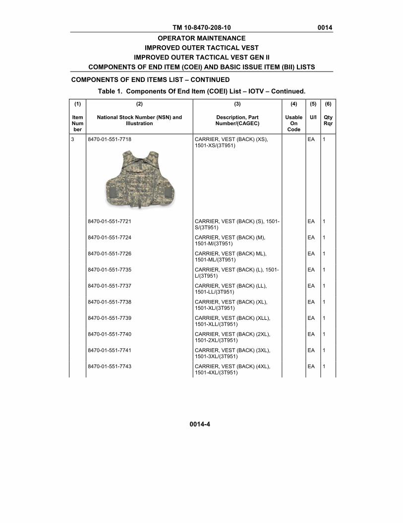
TM 10-8470-208-10 0014 OPERATOR MAINTENANCE
IMPROVED OUTER TACTICAL VEST IMPROVED OUTER TACTICAL VEST GEN II
COMPONENTS OF END ITEM (COEI) AND BASIC ISSUE ITEM (BII) LISTS
COMPONENTS OF END ITEMS LIST – CONTINUED
Table 1. Components Of End Item (COEI) List – IOTV – Continued.
0014-4
(1)
Item Number
(2)
National Stock Number (NSN) and Illustration
(3)
Description, Part Number/(CAGEC)
(4)
Usable On
Code
(5)
U/I
(6)
QtyRqr
3 8470-01-551-7718
CARRIER, VEST (BACK) (XS), 1501-XS/(3T951)
EA 1
8470-01-551-7721 CARRIER, VEST (BACK) (S), 1501-S/(3T951)
EA 1
8470-01-551-7724 CARRIER, VEST (BACK) (M), 1501-M/(3T951)
EA 1
8470-01-551-7726 CARRIER, VEST (BACK) ML), 1501-ML/(3T951)
EA 1
8470-01-551-7735 CARRIER, VEST (BACK) (L), 1501-L/(3T951)
EA 1
8470-01-551-7737 CARRIER, VEST (BACK) (LL), 1501-LL/(3T951)
EA 1
8470-01-551-7738 CARRIER, VEST (BACK) (XL), 1501-XL/(3T951)
EA 1
8470-01-551-7739 CARRIER, VEST (BACK) (XLL), 1501-XLL/(3T951)
EA 1
8470-01-551-7740 CARRIER, VEST (BACK) (2XL), 1501-2XL/(3T951)
EA 1
8470-01-551-7741 CARRIER, VEST (BACK) (3XL), 1501-3XL/(3T951)
EA 1
8470-01-551-7743 CARRIER, VEST (BACK) (4XL), 1501-4XL/(3T951)
EA 1

TM 10-8470-208-10 0014 OPERATOR MAINTENANCE
IMPROVED OUTER TACTICAL VEST IMPROVED OUTER TACTICAL VEST GEN II
COMPONENTS OF END ITEM (COEI) AND BASIC ISSUE ITEM (BII) LISTS
COMPONENTS OF END ITEMS LIST – CONTINUED
Table 1. Components Of End Item (COEI) List – IOTV – Continued.
0014-5
(1)
Item Number
(2)
National Stock Number (NSN) and Illustration
(3)
Description, Part Number/(CAGEC)
(4)
Usable On
Code
(5)
U/I
(6)
QtyRqr
4 8470-01-551-8057
INSERT, BALLISTIC (BACK) (XS), 1503-XS/(3T951)
EA 1
8470-01-551-8058 INSERT, BALLISTIC (BACK) (S), 1503-S/(3T951)
EA 1
8470-01-551-8062 INSERT, BALLISTIC (BACK) (M), 1503-M/(3T951)
EA 1
8470-01-551-8063 INSERT, BALLISTIC (BACK) (ML), 1503-ML/(3T951)
EA 1
8470-01-551-8064 INSERT, BALLISTIC (BACK) (L), 1503-L/(3T951)
EA 1
8470-01-551-8074 INSERT, BALLISTIC (BACK) (LL), 1503-LL/(3T951)
EA 1
8470-01-551-8075 INSERT, BALLISTIC (BACK) (XL), 1503-XL/(3T951)
EA 1
8470-01-551-8079 INSERT, BALLISTIC (BACK) (XLL), 1503-XLL/(3T951)
EA 1
8470-01-551-8078 INSERT, BALLISTIC (BACK) (2XL), 1503-2XL/(3T951)
EA 1
8470-01-551-8086 INSERT, BALLISTIC (BACK) (3XL), 1503-3XL/(3T951)
EA 1
8470-01-551-8087 INSERT, BALLISTIC (BACK) (4XL), 1503-4XL/(3T951)
EA 1
5 8470-01-551-8093
CARRIER, SIDE PLATE (RIGHT EXTERNAL) (XS-S), 1507-XSS/(3T951)
EA 1

TM 10-8470-208-10 0014 OPERATOR MAINTENANCE
IMPROVED OUTER TACTICAL VEST IMPROVED OUTER TACTICAL VEST GEN II
COMPONENTS OF END ITEM (COEI) AND BASIC ISSUE ITEM (BII) LISTS
COMPONENTS OF END ITEMS LIST – CONTINUED
Table 1. Components Of End Item (COEI) List – IOTV – Continued.
0014-6
(1)
Item Number
(2)
National Stock Number (NSN) and Illustration
(3)
Description, Part Number/(CAGEC)
(4)
Usable On
Code
(5)
U/I
(6)
QtyRqr
8470-01-551-8095 CARRIER, SIDE PLATE (RIGHT EXTERNAL) (M-L), 1507-MLG/(3T951)
EA 1
8470-01-551-8096 CARRIER, SIDE PLATE (RIGHT EXTERNAL) (XL-2XL), 1507-X2L/(3T951)
EA 1
8470-01-551-8101 CARRIER, SIDE PLATE (RIGHT EXTERNAL) (3XL-4XL), 1507-X34/(3T951)
EA 1
6 8470-01-551-8113
CARRIER, SIDE PLATE (LEFT EXTERNAL) (XS-S), 1508-XSS/(3T951)
EA 1
8470-01-551-8114 CARRIER, SIDE PLATE (LEFT EXTERNAL) (M-L), 1508-MLG/(3T951)
EA 1
8470-01-551-8115 CARRIER, SIDE PLATE (LEFT EXTERNAL) (XL-2XL), 1508-X2L/(3T951)
EA 1
8470-01-551-8120 CARRIER, SIDE PLATE (LEFT EXTERNAL) (3XL-4XL), 1508-X34/(3T951)
EA 1
7 8470-01-551-8631
BODY ARMOR, WAISTBAND (RIGHT INTERNAL ELASTIC BAND) (XS-S), 1509-XSS/(3T951)
EA 1
8470-01-551-8632 BODY ARMOR, WAISTBAND (RIGHT INTERNAL ELASTIC BAND) (M-L), 1509-MLG/(3T951)
EA 1
8470-01-551-8633 BODY ARMOR, WAISTBAND (RIGHT INTERNAL ELASTIC BAND) (XL-2XL), 1509-X2L/(3T951)
EA 1

TM 10-8470-208-10 0014 OPERATOR MAINTENANCE
IMPROVED OUTER TACTICAL VEST IMPROVED OUTER TACTICAL VEST GEN II
COMPONENTS OF END ITEM (COEI) AND BASIC ISSUE ITEM (BII) LISTS
COMPONENTS OF END ITEMS LIST – CONTINUED
Table 1. Components Of End Item (COEI) List – IOTV – Continued.
0014-7
(1)
Item Number
(2)
National Stock Number (NSN) and Illustration
(3)
Description, Part Number/(CAGEC)
(4)
Usable On
Code
(5)
U/I
(6)
QtyRqr
8470-01-551-8634 BODY ARMOR, WAISTBAND (RIGHT INTERNAL ELASTIC BAND) (3XL-4XL), 1509-X34/(3T951)
EA 1
8 8470-01-551-8620
BODY ARMOR, WAISTBAND (LEFT INTERNAL ELASTIC BAND) (XS-S), 1510-XSS/(3T951)
EA 1
8470-01-551-8623 BODY ARMOR, WAISTBAND (LEFT INTERNAL ELASTIC BAND) (M-L), 1510-MLG/(3T951)
EA 1
8470-01-551-8624 BODY ARMOR, WAISTBAND (LEFT INTERNAL ELASTIC BAND) (XL-2XL), 1510-X2L/(3T951)
EA 1
8470-01-551-8627 BODY ARMOR, WAISTBAND (LEFT INTERNAL ELASTIC BAND) (3XL-4XL), 1510-X34/(3T951)
EA 1
9 8305-01-551-8940
CORD,CABLE ASSEMBLY,IMPROVED OUTER TACTICAL VEST (CABLE RELEASE ASSEMBLY(XS-S), 1513-L60/(3T951)
EA 1
8305-01-551-8941 CORD,CABLE ASSEMBLY,IMPROVED OUTER TACTICAL VEST (CABLE RELEASE ASSEMBLY(M-L), 1513-L62/(3T951)
EA 1
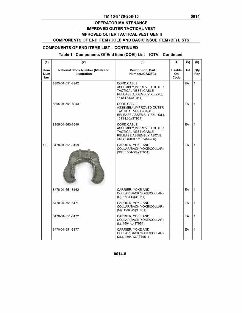
TM 10-8470-208-10 0014 OPERATOR MAINTENANCE
IMPROVED OUTER TACTICAL VEST IMPROVED OUTER TACTICAL VEST GEN II
COMPONENTS OF END ITEM (COEI) AND BASIC ISSUE ITEM (BII) LISTS
COMPONENTS OF END ITEMS LIST – CONTINUED
Table 1. Components Of End Item (COEI) List – IOTV – Continued.
0014-8
(1)
Item Number
(2)
National Stock Number (NSN) and Illustration
(3)
Description, Part Number/(CAGEC)
(4)
Usable On
Code
(5)
U/I
(6)
QtyRqr
8305-01-551-8942 CORD,CABLE ASSEMBLY,IMPROVED OUTER TACTICAL VEST (CABLE RELEASE ASSEMBLY(XL-2XL), 1513-L64/(3T951)
EA 1
8305-01-551-8943 CORD,CABLE ASSEMBLY,IMPROVED OUTER TACTICAL VEST (CABLE RELEASE ASSEMBLY(3XL-4XL), 1513-L66/(3T951)
EA 1
8305-01-560-6949 CORD,CABLE ASSEMBLY,IMPROVED OUTER TACTICAL VEST (CABLE RELEASE ASSEMBLY(ABOVE 4XL), GC09477105/(54786)
EA 1
10 8470-01-551-8159
CARRIER, YOKE AND COLLAR(BACK YOKE/COLLAR) (XS), 1504-XS/(3T951)
EA 1
8470-01-551-8162 CARRIER, YOKE AND COLLAR(BACK YOKE/COLLAR) (S), 1504-S/(3T951)
EA 1
8470-01-551-8171 CARRIER, YOKE AND COLLAR(BACK YOKE/COLLAR) (M), 1504-M/(3T951)
EA 1
8470-01-551-8172 CARRIER, YOKE AND COLLAR(BACK YOKE/COLLAR) (L), 1504-L/(3T951)
EA 1
8470-01-551-8177 CARRIER, YOKE AND COLLAR(BACK YOKE/COLLAR) (XL), 1504-XL/(3T951)
EA 1
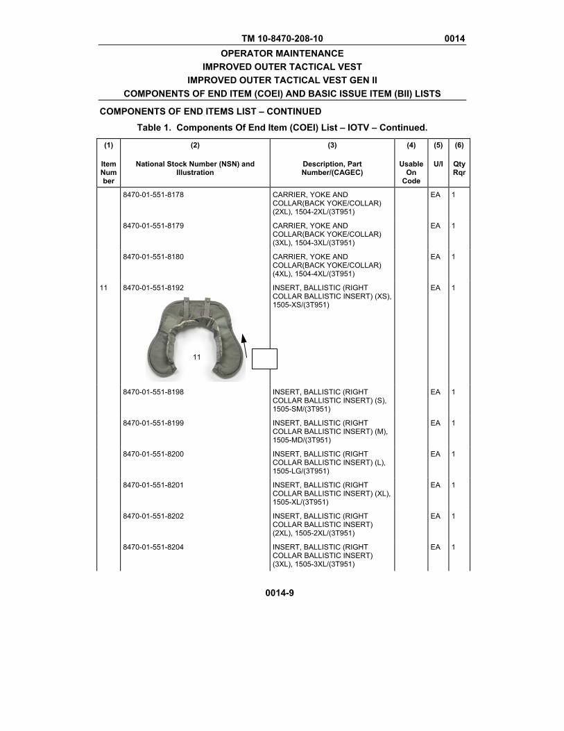
TM 10-8470-208-10 0014 OPERATOR MAINTENANCE
IMPROVED OUTER TACTICAL VEST IMPROVED OUTER TACTICAL VEST GEN II
COMPONENTS OF END ITEM (COEI) AND BASIC ISSUE ITEM (BII) LISTS
COMPONENTS OF END ITEMS LIST – CONTINUED
Table 1. Components Of End Item (COEI) List – IOTV – Continued.
0014-9
(1)
Item Number
(2)
National Stock Number (NSN) and Illustration
(3)
Description, Part Number/(CAGEC)
(4)
Usable On
Code
(5)
U/I
(6)
QtyRqr
8470-01-551-8178 CARRIER, YOKE AND COLLAR(BACK YOKE/COLLAR) (2XL), 1504-2XL/(3T951)
EA 1
8470-01-551-8179 CARRIER, YOKE AND COLLAR(BACK YOKE/COLLAR) (3XL), 1504-3XL/(3T951)
EA 1
8470-01-551-8180 CARRIER, YOKE AND COLLAR(BACK YOKE/COLLAR) (4XL), 1504-4XL/(3T951)
EA 1
11 8470-01-551-8192
INSERT, BALLISTIC (RIGHT COLLAR BALLISTIC INSERT) (XS), 1505-XS/(3T951)
EA 1
8470-01-551-8198 INSERT, BALLISTIC (RIGHT COLLAR BALLISTIC INSERT) (S), 1505-SM/(3T951)
EA 1
8470-01-551-8199 INSERT, BALLISTIC (RIGHT COLLAR BALLISTIC INSERT) (M), 1505-MD/(3T951)
EA 1
8470-01-551-8200 INSERT, BALLISTIC (RIGHT COLLAR BALLISTIC INSERT) (L), 1505-LG/(3T951)
EA 1
8470-01-551-8201 INSERT, BALLISTIC (RIGHT COLLAR BALLISTIC INSERT) (XL), 1505-XL/(3T951)
EA 1
8470-01-551-8202 INSERT, BALLISTIC (RIGHT COLLAR BALLISTIC INSERT) (2XL), 1505-2XL/(3T951)
EA 1
8470-01-551-8204 INSERT, BALLISTIC (RIGHT COLLAR BALLISTIC INSERT) (3XL), 1505-3XL/(3T951)
EA 1
11
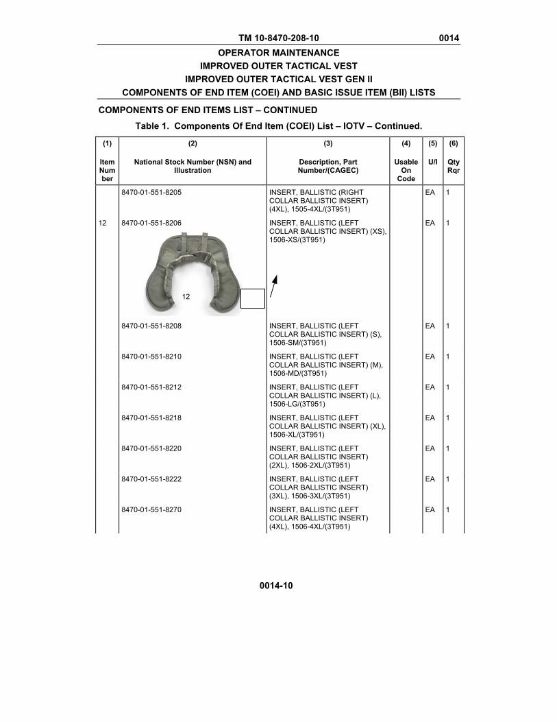
TM 10-8470-208-10 0014 OPERATOR MAINTENANCE
IMPROVED OUTER TACTICAL VEST IMPROVED OUTER TACTICAL VEST GEN II
COMPONENTS OF END ITEM (COEI) AND BASIC ISSUE ITEM (BII) LISTS
COMPONENTS OF END ITEMS LIST – CONTINUED
Table 1. Components Of End Item (COEI) List – IOTV – Continued.
0014-10
(1)
Item Number
(2)
National Stock Number (NSN) and Illustration
(3)
Description, Part Number/(CAGEC)
(4)
Usable On
Code
(5)
U/I
(6)
QtyRqr
8470-01-551-8205 INSERT, BALLISTIC (RIGHT COLLAR BALLISTIC INSERT) (4XL), 1505-4XL/(3T951)
EA 1
12 8470-01-551-8206
INSERT, BALLISTIC (LEFT COLLAR BALLISTIC INSERT) (XS), 1506-XS/(3T951)
EA 1
8470-01-551-8208 INSERT, BALLISTIC (LEFT COLLAR BALLISTIC INSERT) (S), 1506-SM/(3T951)
EA 1
8470-01-551-8210 INSERT, BALLISTIC (LEFT COLLAR BALLISTIC INSERT) (M), 1506-MD/(3T951)
EA 1
8470-01-551-8212 INSERT, BALLISTIC (LEFT COLLAR BALLISTIC INSERT) (L), 1506-LG/(3T951)
EA 1
8470-01-551-8218 INSERT, BALLISTIC (LEFT COLLAR BALLISTIC INSERT) (XL), 1506-XL/(3T951)
EA 1
8470-01-551-8220 INSERT, BALLISTIC (LEFT COLLAR BALLISTIC INSERT) (2XL), 1506-2XL/(3T951)
EA 1
8470-01-551-8222 INSERT, BALLISTIC (LEFT COLLAR BALLISTIC INSERT) (3XL), 1506-3XL/(3T951)
EA 1
8470-01-551-8270 INSERT, BALLISTIC (LEFT COLLAR BALLISTIC INSERT) (4XL), 1506-4XL/(3T951)
EA 1
12
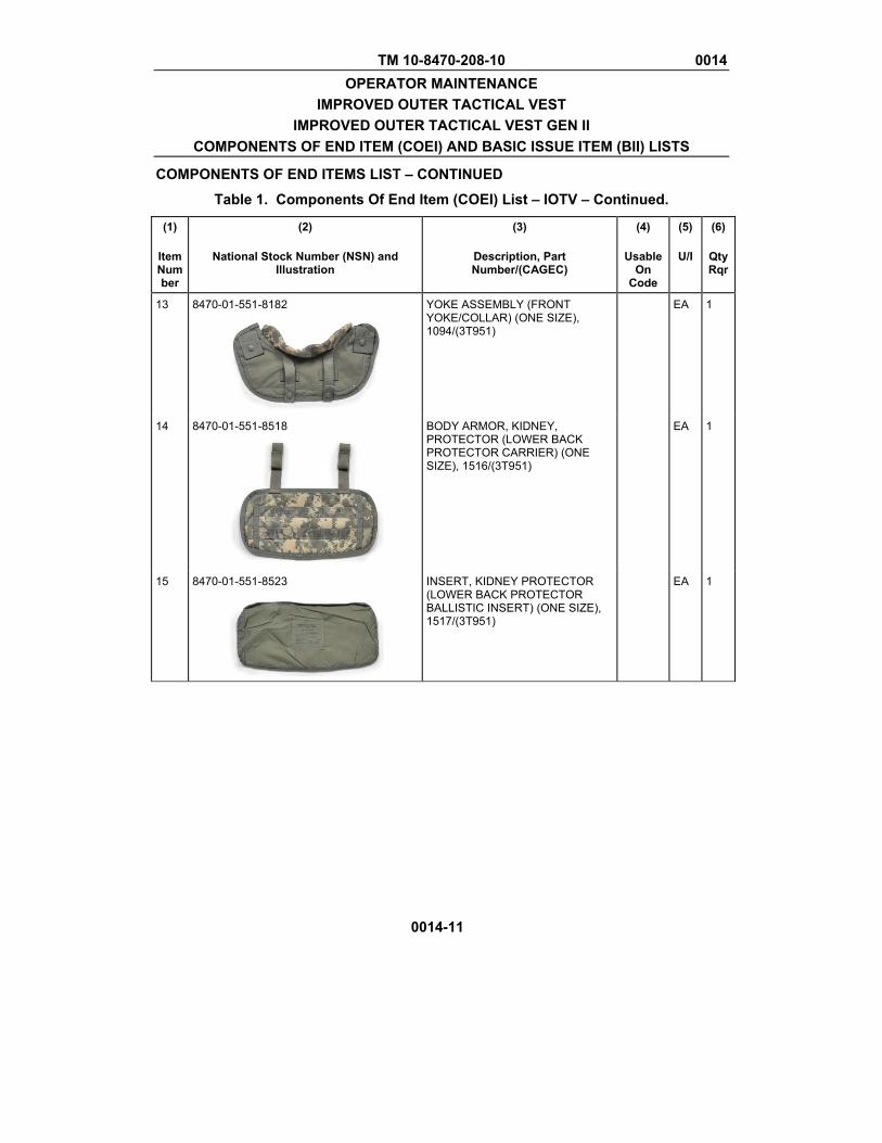
TM 10-8470-208-10 0014 OPERATOR MAINTENANCE
IMPROVED OUTER TACTICAL VEST IMPROVED OUTER TACTICAL VEST GEN II
COMPONENTS OF END ITEM (COEI) AND BASIC ISSUE ITEM (BII) LISTS
COMPONENTS OF END ITEMS LIST – CONTINUED
Table 1. Components Of End Item (COEI) List – IOTV – Continued.
0014-11
(1)
Item Number
(2)
National Stock Number (NSN) and Illustration
(3)
Description, Part Number/(CAGEC)
(4)
Usable On
Code
(5)
U/I
(6)
QtyRqr
13 8470-01-551-8182
YOKE ASSEMBLY (FRONT YOKE/COLLAR) (ONE SIZE), 1094/(3T951)
EA 1
14 8470-01-551-8518
BODY ARMOR, KIDNEY, PROTECTOR (LOWER BACK PROTECTOR CARRIER) (ONE SIZE), 1516/(3T951)
EA 1
15 8470-01-551-8523
INSERT, KIDNEY PROTECTOR (LOWER BACK PROTECTOR BALLISTIC INSERT) (ONE SIZE), 1517/(3T951)
EA 1
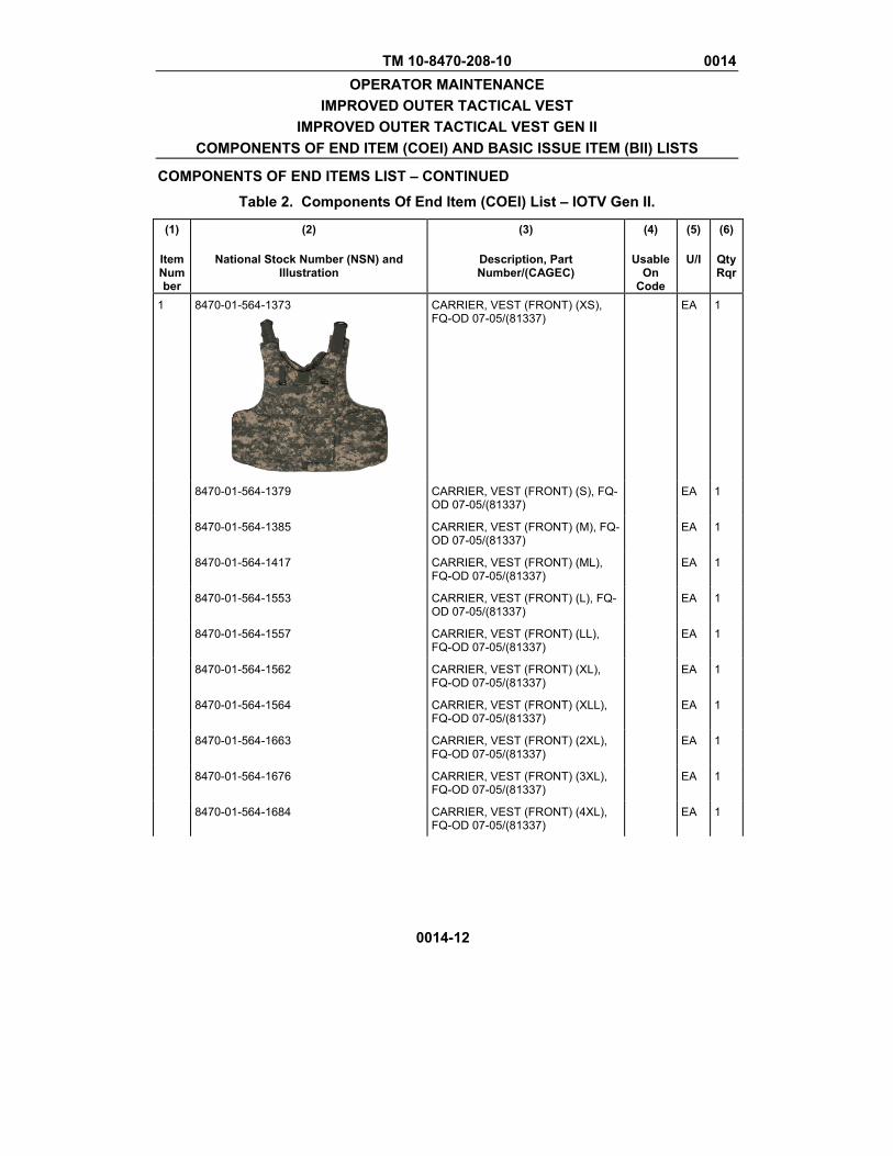
TM 10-8470-208-10 0014 OPERATOR MAINTENANCE
IMPROVED OUTER TACTICAL VEST IMPROVED OUTER TACTICAL VEST GEN II
COMPONENTS OF END ITEM (COEI) AND BASIC ISSUE ITEM (BII) LISTS
COMPONENTS OF END ITEMS LIST – CONTINUED
0014-12
Table 2. Components Of End Item (COEI) List – IOTV Gen II.
(1)
Item Number
(2)
National Stock Number (NSN) and Illustration
(3)
Description, Part Number/(CAGEC)
(4)
Usable On
Code
(5)
U/I
(6)
QtyRqr
1 8470-01-564-1373
CARRIER, VEST (FRONT) (XS), FQ-OD 07-05/(81337)
EA 1
8470-01-564-1379 CARRIER, VEST (FRONT) (S), FQ-OD 07-05/(81337)
EA 1
8470-01-564-1385 CARRIER, VEST (FRONT) (M), FQ-OD 07-05/(81337)
EA 1
8470-01-564-1417 CARRIER, VEST (FRONT) (ML), FQ-OD 07-05/(81337)
EA 1
8470-01-564-1553 CARRIER, VEST (FRONT) (L), FQ-OD 07-05/(81337)
EA 1
8470-01-564-1557 CARRIER, VEST (FRONT) (LL), FQ-OD 07-05/(81337)
EA 1
8470-01-564-1562 CARRIER, VEST (FRONT) (XL), FQ-OD 07-05/(81337)
EA 1
8470-01-564-1564 CARRIER, VEST (FRONT) (XLL), FQ-OD 07-05/(81337)
EA 1
8470-01-564-1663 CARRIER, VEST (FRONT) (2XL), FQ-OD 07-05/(81337)
EA 1
8470-01-564-1676 CARRIER, VEST (FRONT) (3XL), FQ-OD 07-05/(81337)
EA 1
8470-01-564-1684 CARRIER, VEST (FRONT) (4XL), FQ-OD 07-05/(81337)
EA 1
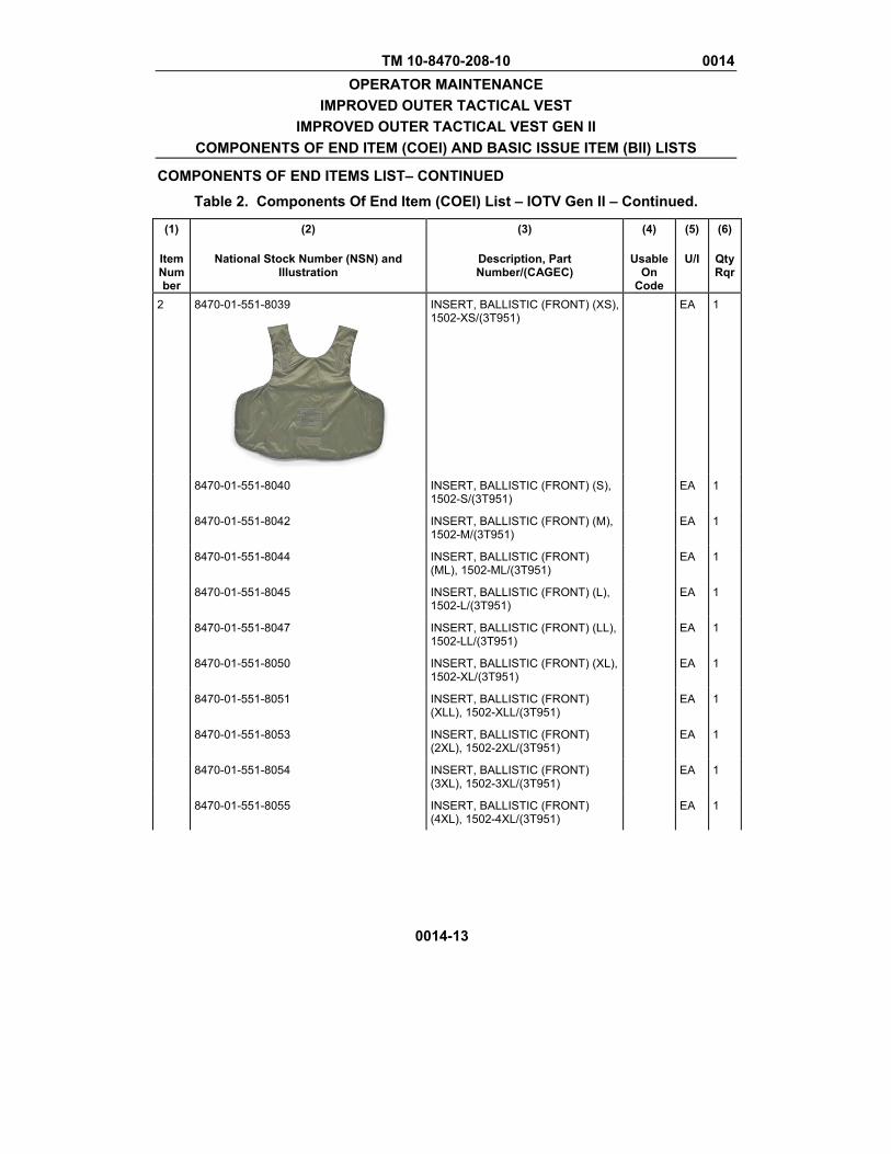
TM 10-8470-208-10 0014 OPERATOR MAINTENANCE
IMPROVED OUTER TACTICAL VEST IMPROVED OUTER TACTICAL VEST GEN II
COMPONENTS OF END ITEM (COEI) AND BASIC ISSUE ITEM (BII) LISTS
COMPONENTS OF END ITEMS LIST– CONTINUED
Table 2. Components Of End Item (COEI) List – IOTV Gen II – Continued.
0014-13
(1)
Item Number
(2)
National Stock Number (NSN) and Illustration
(3)
Description, Part Number/(CAGEC)
(4)
Usable On
Code
(5)
U/I
(6)
QtyRqr
2 8470-01-551-8039
INSERT, BALLISTIC (FRONT) (XS), 1502-XS/(3T951)
EA 1
8470-01-551-8040 INSERT, BALLISTIC (FRONT) (S), 1502-S/(3T951)
EA 1
8470-01-551-8042 INSERT, BALLISTIC (FRONT) (M), 1502-M/(3T951)
EA 1
8470-01-551-8044 INSERT, BALLISTIC (FRONT) (ML), 1502-ML/(3T951)
EA 1
8470-01-551-8045 INSERT, BALLISTIC (FRONT) (L), 1502-L/(3T951)
EA 1
8470-01-551-8047 INSERT, BALLISTIC (FRONT) (LL), 1502-LL/(3T951)
EA 1
8470-01-551-8050 INSERT, BALLISTIC (FRONT) (XL), 1502-XL/(3T951)
EA 1
8470-01-551-8051 INSERT, BALLISTIC (FRONT) (XLL), 1502-XLL/(3T951)
EA 1
8470-01-551-8053 INSERT, BALLISTIC (FRONT) (2XL), 1502-2XL/(3T951)
EA 1
8470-01-551-8054 INSERT, BALLISTIC (FRONT) (3XL), 1502-3XL/(3T951)
EA 1
8470-01-551-8055 INSERT, BALLISTIC (FRONT) (4XL), 1502-4XL/(3T951)
EA 1

TM 10-8470-208-10 0014 OPERATOR MAINTENANCE
IMPROVED OUTER TACTICAL VEST IMPROVED OUTER TACTICAL VEST GEN II
COMPONENTS OF END ITEM (COEI) AND BASIC ISSUE ITEM (BII) LISTS
COMPONENTS OF END ITEMS LIST– CONTINUED
Table 2. Components Of End Item (COEI) List – IOTV Gen II – Continued.
0014-14
(1)
Item Number
(2)
National Stock Number (NSN) and Illustration
(3)
Description, Part Number/(CAGEC)
(4)
Usable On
Code
(5)
U/I
(6)
QtyRqr
3 8470-01-564-1733
CARRIER, VEST (BACK) (XS), FQ-OD 07-05/(81337)
EA 1
8470-01-564-1755 CARRIER, VEST (BACK) (S), FQ-OD 07-05/(81337)
EA 1
8470-01-564-1978 CARRIER, VEST (BACK) (M), FQ-OD 07-05/(81337)
EA 1
8470-01-564-1988 CARRIER, VEST (BACK) ML), FQ-OD 07-05/(81337)
EA 1
8470-01-564-2000 CARRIER, VEST (BACK) (L), FQ-OD 07-05/(81337)
EA 1
8470-01-564-2007 CARRIER, VEST (BACK) (LL), FQ-OD 07-05/(81337)
EA 1
8470-01-564-2013 CARRIER, VEST (BACK) (XL), FQ-OD 07-05/(81337)
EA 1
8470-01-564-2030 CARRIER, VEST (BACK) (XLL), FQ-OD 07-05/(81337)
EA 1
8470-01-564-2035 CARRIER, VEST (BACK) (2XL), FQ-OD 07-05/(81337)
EA 1
8470-01-564-2039 CARRIER, VEST (BACK) (3XL), FQ-OD 07-05/(81337)
EA 1
8470-01-564-2336 CARRIER, VEST (BACK) (4XL), FQ-OD 07-05/(81337)
EA 1
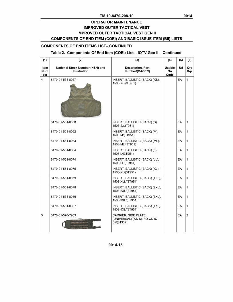
TM 10-8470-208-10 0014 OPERATOR MAINTENANCE
IMPROVED OUTER TACTICAL VEST IMPROVED OUTER TACTICAL VEST GEN II
COMPONENTS OF END ITEM (COEI) AND BASIC ISSUE ITEM (BII) LISTS
COMPONENTS OF END ITEMS LIST– CONTINUED
Table 2. Components Of End Item (COEI) List – IOTV Gen II – Continued.
0014-15
(1)
Item Number
(2)
National Stock Number (NSN) and Illustration
(3)
Description, Part Number/(CAGEC)
(4)
Usable On
Code
(5)
U/I
(6)
QtyRqr
4 8470-01-551-8057
INSERT, BALLISTIC (BACK) (XS), 1503-XS/(3T951)
EA 1
8470-01-551-8058 INSERT, BALLISTIC (BACK) (S), 1503-S/(3T951)
EA 1
8470-01-551-8062 INSERT, BALLISTIC (BACK) (M), 1503-M/(3T951)
EA 1
8470-01-551-8063 INSERT, BALLISTIC (BACK) (ML), 1503-ML/(3T951)
EA 1
8470-01-551-8064 INSERT, BALLISTIC (BACK) (L), 1503-L/(3T951)
EA 1
8470-01-551-8074 INSERT, BALLISTIC (BACK) (LL), 1503-LL/(3T951)
EA 1
8470-01-551-8075 INSERT, BALLISTIC (BACK) (XL), 1503-XL/(3T951)
EA 1
8470-01-551-8079 INSERT, BALLISTIC (BACK) (XLL), 1503-XLL/(3T951)
EA 1
8470-01-551-8078 INSERT, BALLISTIC (BACK) (2XL), 1503-2XL/(3T951)
EA 1
8470-01-551-8086 INSERT, BALLISTIC (BACK) (3XL), 1503-3XL/(3T951)
EA 1
8470-01-551-8087 INSERT, BALLISTIC (BACK) (4XL), 1503-4XL/(3T951)
EA 1
5 8470-01-576-7903
CARRIER, SIDE PLATE (UNIVERSAL) (XS-S), FQ-OD 07-05/(81337)
EA 2
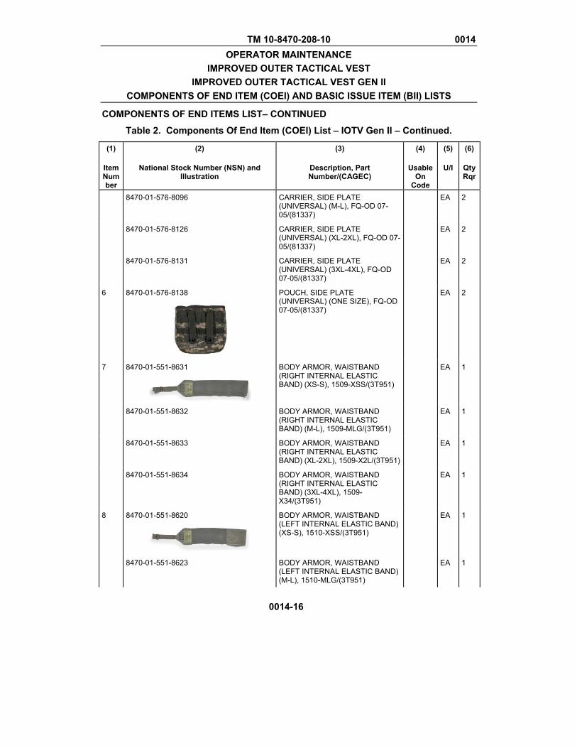
TM 10-8470-208-10 0014 OPERATOR MAINTENANCE
IMPROVED OUTER TACTICAL VEST IMPROVED OUTER TACTICAL VEST GEN II
COMPONENTS OF END ITEM (COEI) AND BASIC ISSUE ITEM (BII) LISTS
COMPONENTS OF END ITEMS LIST– CONTINUED
Table 2. Components Of End Item (COEI) List – IOTV Gen II – Continued.
0014-16
(1)
Item Number
(2)
National Stock Number (NSN) and Illustration
(3)
Description, Part Number/(CAGEC)
(4)
Usable On
Code
(5)
U/I
(6)
QtyRqr
8470-01-576-8096 CARRIER, SIDE PLATE (UNIVERSAL) (M-L), FQ-OD 07-05/(81337)
EA 2
8470-01-576-8126 CARRIER, SIDE PLATE (UNIVERSAL) (XL-2XL), FQ-OD 07-05/(81337)
EA 2
8470-01-576-8131 CARRIER, SIDE PLATE (UNIVERSAL) (3XL-4XL), FQ-OD 07-05/(81337)
EA 2
6 8470-01-576-8138
POUCH, SIDE PLATE (UNIVERSAL) (ONE SIZE), FQ-OD 07-05/(81337)
EA 2
7 8470-01-551-8631
BODY ARMOR, WAISTBAND (RIGHT INTERNAL ELASTIC BAND) (XS-S), 1509-XSS/(3T951)
EA 1
8470-01-551-8632 BODY ARMOR, WAISTBAND (RIGHT INTERNAL ELASTIC BAND) (M-L), 1509-MLG/(3T951)
EA 1
8470-01-551-8633 BODY ARMOR, WAISTBAND (RIGHT INTERNAL ELASTIC BAND) (XL-2XL), 1509-X2L/(3T951)
EA 1
8470-01-551-8634 BODY ARMOR, WAISTBAND (RIGHT INTERNAL ELASTIC BAND) (3XL-4XL), 1509-X34/(3T951)
EA 1
8 8470-01-551-8620
BODY ARMOR, WAISTBAND (LEFT INTERNAL ELASTIC BAND) (XS-S), 1510-XSS/(3T951)
EA 1
8470-01-551-8623 BODY ARMOR, WAISTBAND (LEFT INTERNAL ELASTIC BAND) (M-L), 1510-MLG/(3T951)
EA 1
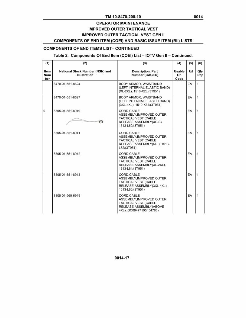
TM 10-8470-208-10 0014 OPERATOR MAINTENANCE
IMPROVED OUTER TACTICAL VEST IMPROVED OUTER TACTICAL VEST GEN II
COMPONENTS OF END ITEM (COEI) AND BASIC ISSUE ITEM (BII) LISTS
COMPONENTS OF END ITEMS LIST– CONTINUED
Table 2. Components Of End Item (COEI) List – IOTV Gen II – Continued.
0014-17
(1)
Item Number
(2)
National Stock Number (NSN) and Illustration
(3)
Description, Part Number/(CAGEC)
(4)
Usable On
Code
(5)
U/I
(6)
QtyRqr
8470-01-551-8624 BODY ARMOR, WAISTBAND (LEFT INTERNAL ELASTIC BAND) (XL-2XL), 1510-X2L/(3T951)
EA 1
8470-01-551-8627 BODY ARMOR, WAISTBAND (LEFT INTERNAL ELASTIC BAND) (3XL-4XL), 1510-X34/(3T951)
EA 1
9 8305-01-551-8940
CORD,CABLE ASSEMBLY,IMPROVED OUTER TACTICAL VEST (CABLE RELEASE ASSEMBLY(XS-S), 1513-L60/(3T951)
EA 1
8305-01-551-8941 CORD,CABLE ASSEMBLY,IMPROVED OUTER TACTICAL VEST (CABLE RELEASE ASSEMBLY(M-L), 1513-L62/(3T951)
EA 1
8305-01-551-8942 CORD,CABLE ASSEMBLY,IMPROVED OUTER TACTICAL VEST (CABLE RELEASE ASSEMBLY(XL-2XL), 1513-L64/(3T951)
EA 1
8305-01-551-8943 CORD,CABLE ASSEMBLY,IMPROVED OUTER TACTICAL VEST (CABLE RELEASE ASSEMBLY(3XL-4XL), 1513-L66/(3T951)
EA 1
8305-01-560-6949 CORD,CABLE ASSEMBLY,IMPROVED OUTER TACTICAL VEST (CABLE RELEASE ASSEMBLY(ABOVE 4XL), GC09477105/(54786)
EA 1
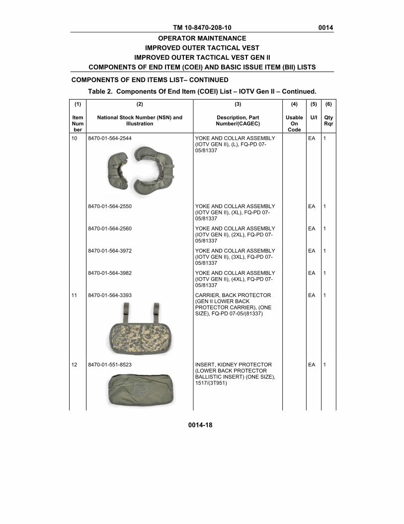
TM 10-8470-208-10 0014 OPERATOR MAINTENANCE
IMPROVED OUTER TACTICAL VEST IMPROVED OUTER TACTICAL VEST GEN II
COMPONENTS OF END ITEM (COEI) AND BASIC ISSUE ITEM (BII) LISTS
COMPONENTS OF END ITEMS LIST– CONTINUED
Table 2. Components Of End Item (COEI) List – IOTV Gen II – Continued.
0014-18
(1)
Item Number
(2)
National Stock Number (NSN) and Illustration
(3)
Description, Part Number/(CAGEC)
(4)
Usable On
Code
(5)
U/I
(6)
QtyRqr
10 8470-01-564-2544
YOKE AND COLLAR ASSEMBLY (IOTV GEN II), (L), FQ-PD 07-05/81337
EA 1
8470-01-564-2550 YOKE AND COLLAR ASSEMBLY (IOTV GEN II), (XL), FQ-PD 07-05/81337
EA 1
8470-01-564-2560 YOKE AND COLLAR ASSEMBLY (IOTV GEN II), (2XL), FQ-PD 07-05/81337
EA 1
8470-01-564-3972 YOKE AND COLLAR ASSEMBLY (IOTV GEN II), (3XL), FQ-PD 07-05/81337
EA 1
8470-01-564-3982 YOKE AND COLLAR ASSEMBLY (IOTV GEN II), (4XL), FQ-PD 07-05/81337
EA 1
11 8470-01-564-3393
CARRIER, BACK PROTECTOR (GEN II LOWER BACK PROTECTOR CARRIER), (ONE SIZE), FQ-PD 07-05/(81337)
EA 1
12 8470-01-551-8523
INSERT, KIDNEY PROTECTOR (LOWER BACK PROTECTOR BALLISTIC INSERT) (ONE SIZE), 1517/(3T951)
EA 1
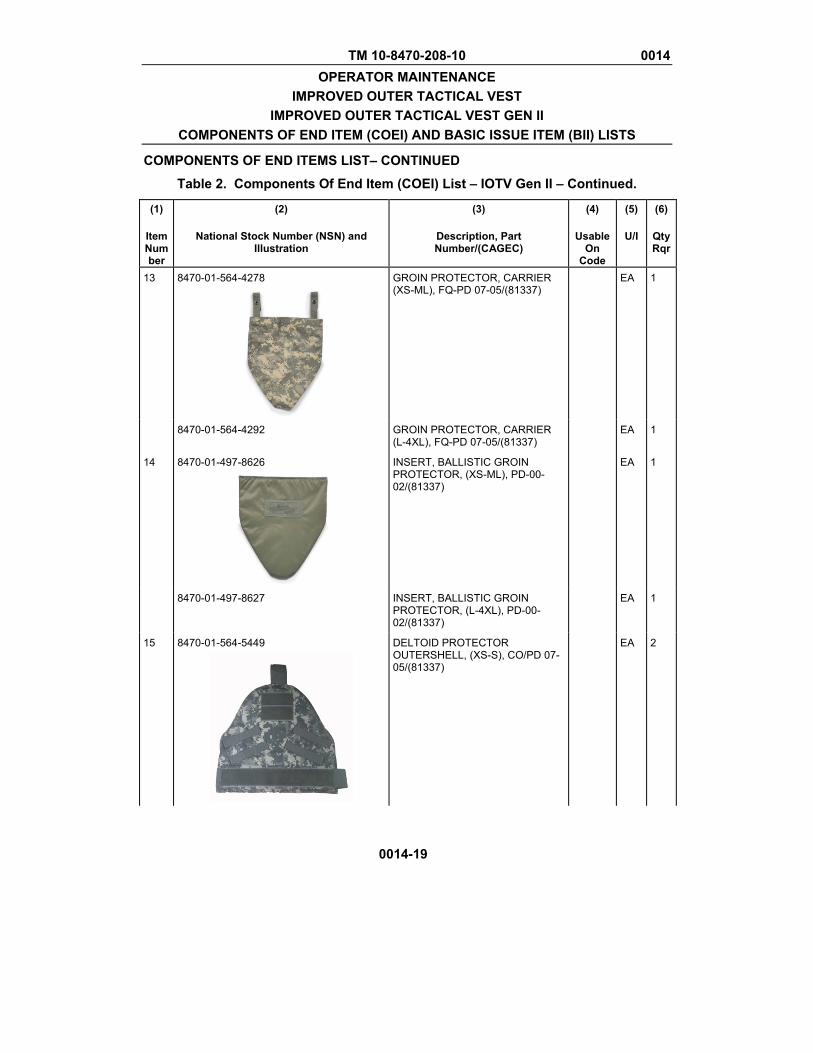
TM 10-8470-208-10 0014 OPERATOR MAINTENANCE
IMPROVED OUTER TACTICAL VEST IMPROVED OUTER TACTICAL VEST GEN II
COMPONENTS OF END ITEM (COEI) AND BASIC ISSUE ITEM (BII) LISTS
COMPONENTS OF END ITEMS LIST– CONTINUED
Table 2. Components Of End Item (COEI) List – IOTV Gen II – Continued.
0014-19
(1)
Item Number
(2)
National Stock Number (NSN) and Illustration
(3)
Description, Part Number/(CAGEC)
(4)
Usable On
Code
(5)
U/I
(6)
QtyRqr
13 8470-01-564-4278
GROIN PROTECTOR, CARRIER (XS-ML), FQ-PD 07-05/(81337)
EA 1
8470-01-564-4292 GROIN PROTECTOR, CARRIER (L-4XL), FQ-PD 07-05/(81337)
EA 1
14 8470-01-497-8626
INSERT, BALLISTIC GROIN PROTECTOR, (XS-ML), PD-00-02/(81337)
EA 1
8470-01-497-8627 INSERT, BALLISTIC GROIN PROTECTOR, (L-4XL), PD-00-02/(81337)
EA 1
15 8470-01-564-5449
DELTOID PROTECTOR OUTERSHELL, (XS-S), CO/PD 07-05/(81337)
EA 2
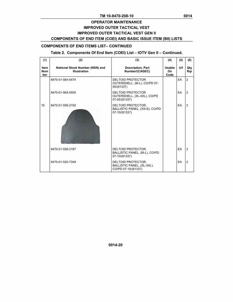
TM 10-8470-208-10 0014 OPERATOR MAINTENANCE
IMPROVED OUTER TACTICAL VEST IMPROVED OUTER TACTICAL VEST GEN II
COMPONENTS OF END ITEM (COEI) AND BASIC ISSUE ITEM (BII) LISTS
COMPONENTS OF END ITEMS LIST– CONTINUED
Table 2. Components Of End Item (COEI) List – IOTV Gen II – Continued.
0014-20
(1)
Item Number
(2)
National Stock Number (NSN) and Illustration
(3)
Description, Part Number/(CAGEC)
(4)
Usable On
Code
(5)
U/I
(6)
QtyRqr
8470-01-564-5474 DELTOID PROTECTOR OUTERSHELL, (M-L), CO/PD 07-05/(81337)
EA 2
8470-01-564-5505 DELTOID PROTECTOR OUTERSHELL, (XL-4XL), CO/PD 07-05/(81337)
EA 2
16 8470-01-556-2192
DELTOID PROTECTOR, BALLISTIC PANEL, (XS-S), CO/PD 07-10/(81337)
EA 2
8470-01-556-2187 DELTOID PROTECTOR, BALLISTIC PANEL, (M-L), CO/PD 07-10/(81337)
EA 2
8470-01-520-7349 DELTOID PROTECTOR, BALLISTIC PANEL, (XL-4XL), CO/PD 07-10/(81337)
EA 2

TM 10-8470-208-10 0014 OPERATOR MAINTENANCE
IMPROVED OUTER TACTICAL VEST IMPROVED OUTER TACTICAL VEST GEN II
COMPONENTS OF END ITEM (COEI) AND BASIC ISSUE ITEM (BII) LISTS
COMPONENTS OF END ITEMS LIST– CONTINUED
0014-21
Table 3. Basic Issue Items (BII) – IOTV.
(1) Item Number
(2) National Stock Number (NSN) and
Illustration
(3) Description, CAGEC, and Part
Number
(4) Usable
On Code
(5) Unit of
Issue
(U/I)
(6)Qty Rqr.
1 N/A
OPERATOR MANUAL FOR IMPROVED OUTER TACTICAL VEST (IOTV) AND IMPROVED OUTER TACTICAL VEST GEN II (IOTV GEN II) PART OF THE INTERCEPTOR BODY ARMOR SYSTEM, 81337, TM 10-8470-208-10
EA 1
2 8470-01-556-2100
DELTOID PROTECTOR OUTERSHELL, (XS-S), CO/PD 07-10/(81337)
EA 2
8470-01-556-2168 DELTOID PROTECTOR OUTERSHELL, (M-L), CO/PD 07-10/(81337)
EA 2
8470-01-526-9657 DELTOID PROTECTOR OUTERSHELL, (XL-4XL), CO/PD 07-10/(81337)
EA 2
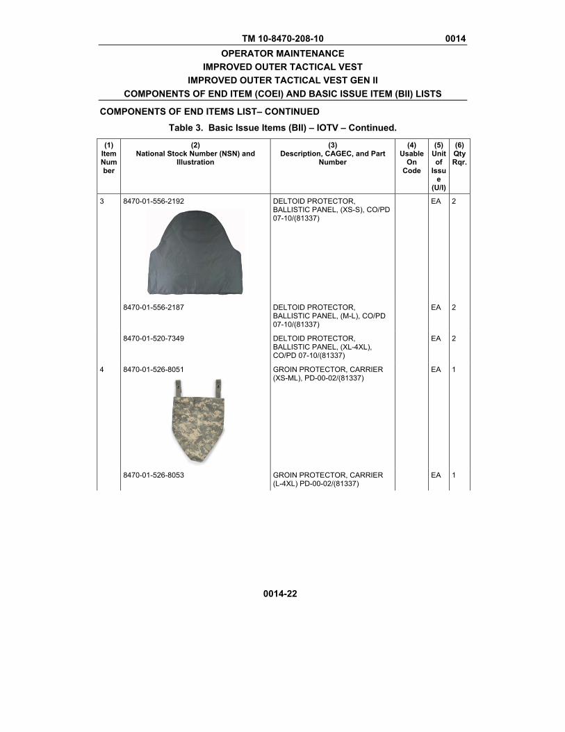
TM 10-8470-208-10 0014 OPERATOR MAINTENANCE
IMPROVED OUTER TACTICAL VEST IMPROVED OUTER TACTICAL VEST GEN II
COMPONENTS OF END ITEM (COEI) AND BASIC ISSUE ITEM (BII) LISTS
COMPONENTS OF END ITEMS LIST– CONTINUED
Table 3. Basic Issue Items (BII) – IOTV – Continued.
0014-22
(1) Item Number
(2) National Stock Number (NSN) and
Illustration
(3) Description, CAGEC, and Part
Number
(4) Usable
On Code
(5) Unit of
Issue
(U/I)
(6)Qty Rqr.
3 8470-01-556-2192
DELTOID PROTECTOR, BALLISTIC PANEL, (XS-S), CO/PD 07-10/(81337)
EA 2
8470-01-556-2187 DELTOID PROTECTOR, BALLISTIC PANEL, (M-L), CO/PD 07-10/(81337)
EA 2
8470-01-520-7349 DELTOID PROTECTOR, BALLISTIC PANEL, (XL-4XL), CO/PD 07-10/(81337)
EA 2
4 8470-01-526-8051
GROIN PROTECTOR, CARRIER (XS-ML), PD-00-02/(81337)
EA 1
8470-01-526-8053 GROIN PROTECTOR, CARRIER (L-4XL) PD-00-02/(81337)
EA 1
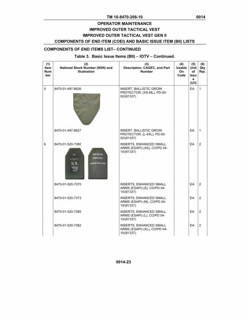
TM 10-8470-208-10 0014 OPERATOR MAINTENANCE
IMPROVED OUTER TACTICAL VEST IMPROVED OUTER TACTICAL VEST GEN II
COMPONENTS OF END ITEM (COEI) AND BASIC ISSUE ITEM (BII) LISTS
COMPONENTS OF END ITEMS LIST– CONTINUED
Table 3. Basic Issue Items (BII) – IOTV – Continued.
0014-23
(1) Item Number
(2) National Stock Number (NSN) and
Illustration
(3) Description, CAGEC, and Part
Number
(4) Usable
On Code
(5) Unit of
Issue
(U/I)
(6)Qty Rqr.
5 8470-01-497-8626
INSERT, BALLISTIC GROIN PROTECTOR, (XS-ML), PD-00-02/(81337)
EA 1
8470-01-497-8627 INSERT, BALLISTIC GROIN PROTECTOR, (L-4XL), PD-00-02/(81337)
EA 1
6 8470-01-520-7360
INSERTS, ENHANCED SMALL ARMS (ESAPI) (XS), CO/PD 04-10/(81337)
EA 2
8470-01-520-7370 INSERTS, ENHANCED SMALL ARMS (ESAPI) (S), CO/PD 04-10/(81337)
EA 2
8470-01-520-7373 INSERTS, ENHANCED SMALL ARMS (ESAPI) (M), CO/PD 04-10/(81337)
EA 2
8470-01-520-7385 INSERTS, ENHANCED SMALL ARMS (ESAPI) (L), CO/PD 04-10/(81337)
EA 2
8470-01-520-7382 INSERTS, ENHANCED SMALL ARMS (ESAPI) (XL), CO/PD 04-10/(81337)
EA 2

TM 10-8470-208-10 0014 OPERATOR MAINTENANCE
IMPROVED OUTER TACTICAL VEST IMPROVED OUTER TACTICAL VEST GEN II
COMPONENTS OF END ITEM (COEI) AND BASIC ISSUE ITEM (BII) LISTS
COMPONENTS OF END ITEMS LIST– CONTINUED
Table 3. Basic Issue Items (BII) – IOTV – Continued.
0014-24
(1) Item Number
(2) National Stock Number (NSN) and
Illustration
(3) Description, CAGEC, and Part
Number
(4) Usable
On Code
(5) Unit of
Issue
(U/I)
(6)Qty Rqr.
7 8470-01-536-7227
INSERTS, SMALL ARMS PROTECTIVE (ESBI) , (ONE SIZE), CO/PD 06-20/(81337)
EA 2
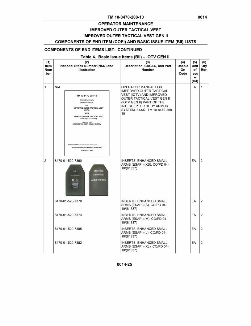
TM 10-8470-208-10 0014 OPERATOR MAINTENANCE
IMPROVED OUTER TACTICAL VEST IMPROVED OUTER TACTICAL VEST GEN II
COMPONENTS OF END ITEM (COEI) AND BASIC ISSUE ITEM (BII) LISTS
COMPONENTS OF END ITEMS LIST– CONTINUED
0014-25
Table 4. Basic Issue Items (BII) – IOTV GEN II.(1)
Item Number
(2) National Stock Number (NSN) and
Illustration
(3) Description, CAGEC, and Part
Number
(4) Usable
On Code
(5) Unit of
Issue
(U/I)
(6)Qty Rqr.
1 N/A
OPERATOR MANUAL FOR IMPROVED OUTER TACTICAL VEST (IOTV) AND IMPROVED OUTER TACTICAL VEST GEN II (IOTV GEN II) PART OF THE INTERCEPTOR BODY ARMOR SYSTEM, 81337, TM 10-8470-208-10
EA 1
2 8470-01-520-7360
INSERTS, ENHANCED SMALL ARMS (ESAPI) (XS), CO/PD 04-10/(81337)
EA 2
8470-01-520-7370 INSERTS, ENHANCED SMALL ARMS (ESAPI) (S), CO/PD 04-10/(81337)
EA 2
8470-01-520-7373 INSERTS, ENHANCED SMALL ARMS (ESAPI) (M), CO/PD 04-10/(81337)
EA 2
8470-01-520-7385 INSERTS, ENHANCED SMALL ARMS (ESAPI) (L), CO/PD 04-10/(81337)
EA 2
8470-01-520-7382 INSERTS, ENHANCED SMALL ARMS (ESAPI) (XL), CO/PD 04-10/(81337)
EA 2
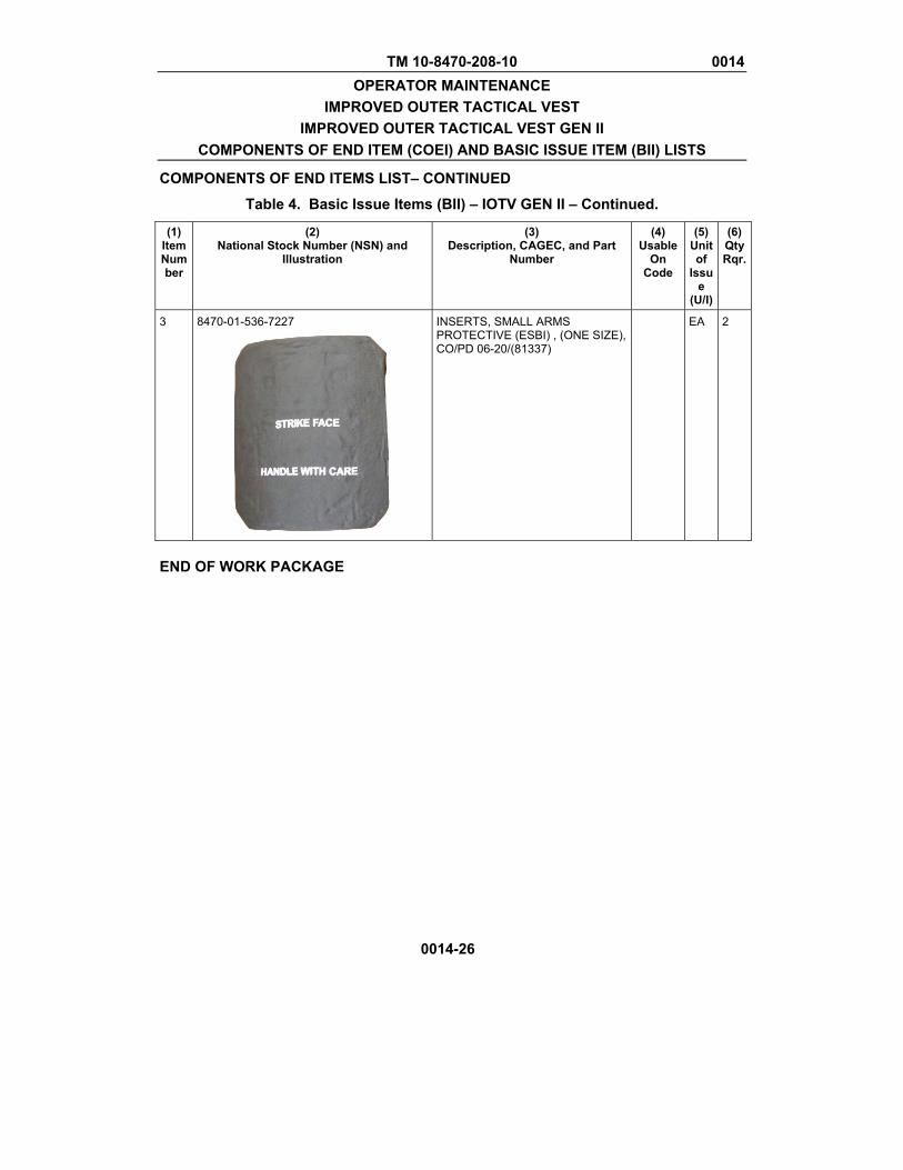
TM 10-8470-208-10 0014 OPERATOR MAINTENANCE
IMPROVED OUTER TACTICAL VEST IMPROVED OUTER TACTICAL VEST GEN II
COMPONENTS OF END ITEM (COEI) AND BASIC ISSUE ITEM (BII) LISTS
COMPONENTS OF END ITEMS LIST– CONTINUED
Table 4. Basic Issue Items (BII) – IOTV GEN II – Continued.
0014-26
(1) Item Number
(2) National Stock Number (NSN) and
Illustration
(3) Description, CAGEC, and Part
Number
(4) Usable
On Code
(5) Unit of
Issue
(U/I)
(6)Qty Rqr.
3 8470-01-536-7227
INSERTS, SMALL ARMS PROTECTIVE (ESBI) , (ONE SIZE), CO/PD 06-20/(81337)
EA 2
END OF WORK PACKAGE
TM 10-8470-208-10 0015 OPERATOR MAINTENANCE
IMPROVED OUTER TACTICAL VEST IMPROVED OUTER TACTICAL VEST GEN II EXPENDABLE AND DURABLE ITEMS LIST
0015-1
EXPENDABLE AND DURABLE ITEMS LIST INTRODUCTION Scope This work package lists expendable and durable items that you will need to operate and maintain the IBA. This list is for information only and is not authority to requisition the listed items. These items are authorized to you by CTA 50-970, Expendable/Durable Items (Except Medical, Class V Repair Parts, and Heraldic Items), CTA 50-909, Field and Garrison Furnishings and Equipments or CTA 8-100, Army Medical Department Expendable/Durable Items. Explanation of Columns in the Expendable/Durable Items List Column (1) Item No. This number is assigned to the entry in the list and is references in the narrative instructions to identify the item (e.g., Use brake fluid (WP 0098, item 5)) Column (2) Level. This column identifies the lowest level of maintenance that requires the listed item (C= Crew). Column (3) National Stock Number (NSN). This is the NSN assigned to the item which you can use to requisition it. Column (4) Item Name, Description, Part Number (CAGEC). This column provides the other information you need to identify the item. The last line below the description is the part number and the Commercial and Government Entity Code (CAGEC) (in parentheses). Column (5) U/I. Unit of Issue (U/I) Code. Shows the physical measurement or count of an item, such as gallon, dozen, gross, etc.
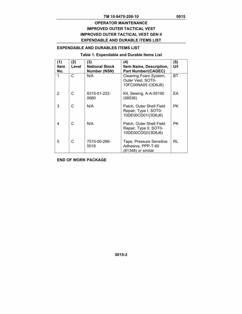
TM 10-8470-208-10 0015 OPERATOR MAINTENANCE
IMPROVED OUTER TACTICAL VEST IMPROVED OUTER TACTICAL VEST GEN II EXPENDABLE AND DURABLE ITEMS LIST
0015-2
EXPENDABLE AND DURABLES ITEMS LIST
Table 1. Expendable and Durable Items List
(1) Item No.
(2) Level
(3) National Stock Number (NSN)
(4) Item Name, Description, Part Number/(CAGEC)
(5) U/I
1 C N/A Cleaning Foam System, Outer Vest, SOT0-10FC00NA05 /(3D6J6)
BT
2 C 8315-01-222-0680
Kit, Sewing, A-A-55190 (58536)
EA
3 C N/A Patch, Outer Shell Field Repair, Type I, SOT0-10DE00CD01/(3D6J6)
PK
4 C N/A Patch, Outer Shell Field Repair, Type II, SOT0-10DE00CD02/(3D6J6)
PK
5 C 7510-00-266-5016
Tape, Pressure Sensitive Adhesive, PPP-T-60 (81348) or similar
RL
END OF WORK PACKAGE
These are the instructions for sending an electronic 2028 The following format must be used if submitting an electronic 2028. The subject line must be exactly the same and all fields must be included; however only the following fields are mandatory: 1, 3, 4, 5, 6, 7, 8, 9, 10, 13, 15, 16, 17, and 27. From: "Whomever" <[email protected]> To: [email protected] Subject: DA Form 2028 1. From: Joe Smith 2. Unit: home 3. Address: 4300 Park 4. City: Hometown 5. St: MO 6. Zip: 77777 7. Date Sent: 19-OCT-93 8. Pub no: 55-2840-229-23 9. Pub Title: TM 10. Publication Date: 04-JUL-85 11. Change Number: 7 12. Submitter Rank: MSG 13. Submitter FName: Joe 14. Submitter MName: T 15. Submitter LName: Smith 16. Submitter Phone: 123-123-1234 17. Problem: 1 18. Page: 2 19. Paragraph: 3 20. Line: 4 21. NSN: 5 22. Reference: 6 23. Figure: 7 24. Table: 8 25. Item: 9 26. Total: 123 27. Text: This is the text for the problem below line 27.

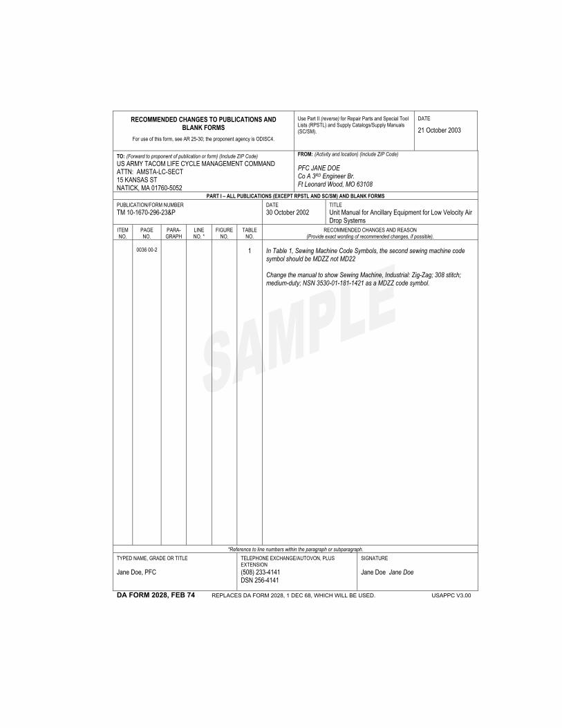
RECOMMENDED CHANGES TO PUBLICATIONS AND BLANK FORMS
For use of this form, see AR 25-30; the proponent agency is ODISC4.
Use Part II (reverse) for Repair Parts and Special Tool Lists (RPSTL) and Supply Catalogs/Supply Manuals (SC/SM).
DATE
21 October 2003
TO: (Forward to proponent of publication or form) (Include ZIP Code) US ARMY TACOM LIFE CYCLE MANAGEMENT COMMAND ATTN: AMSTA-LC-SECT 15 KANSAS ST NATICK, MA 01760-5052
FROM: (Activity and location) (Include ZIP Code) PFC JANE DOE Co A 3RD Engineer Br. Ft Leonard Wood, MO 63108
PART I – ALL PUBLICATIONS (EXCEPT RPSTL AND SC/SM) AND BLANK FORMS PUBLICATION/FORM NUMBER TM 10-1670-296-23&P
DATE 30 October 2002
TITLE Unit Manual for Ancillary Equipment for Low Velocity Air Drop Systems
ITEM NO.
PAGE NO.
PARA- GRAPH
LINE NO. *
FIGURE NO.
TABLE NO.
RECOMMENDED CHANGES AND REASON (Provide exact wording of recommended changes, if possible).
0036 00-2
1 In Table 1, Sewing Machine Code Symbols, the second sewing machine code
symbol should be MDZZ not MD22 Change the manual to show Sewing Machine, Industrial: Zig-Zag; 308 stitch; medium-duty; NSN 3530-01-181-1421 as a MDZZ code symbol.
*Reference to line numbers within the paragraph or subparagraph. TYPED NAME, GRADE OR TITLE Jane Doe, PFC
TELEPHONE EXCHANGE/AUTOVON, PLUS EXTENSION (508) 233-4141 DSN 256-4141
SIGNATURE Jane Doe Jane Doe
DA FORM 2028, FEB 74 REPLACES DA FORM 2028, 1 DEC 68, WHICH WILL BE USED. USAPPC V3.00
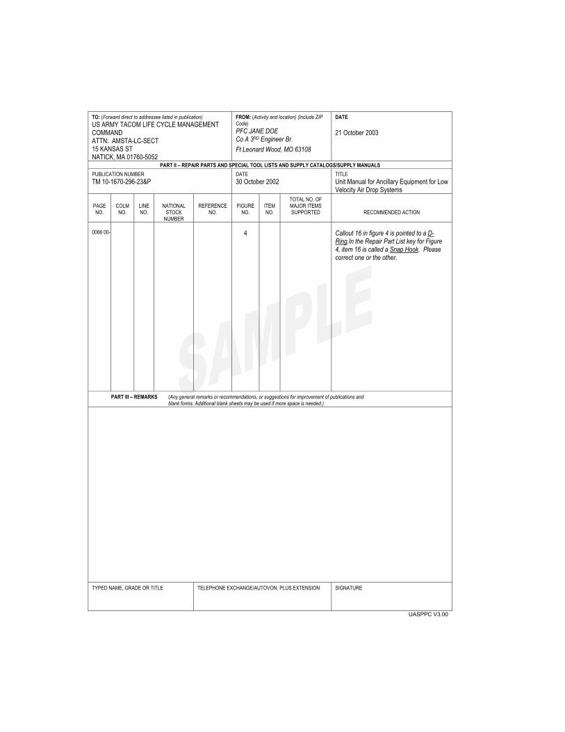
TO: (Forward direct to addressee listed in publication) US ARMY TACOM LIFE CYCLE MANAGEMENT COMMAND ATTN: AMSTA-LC-SECT 15 KANSAS ST NATICK, MA 01760-5052
FROM: (Activity and location) (Include ZIP Code) PFC JANE DOE Co A 3RD Engineer Br. Ft Leonard Wood, MO 63108
DATE 21 October 2003
PART II – REPAIR PARTS AND SPECIAL TOOL LISTS AND SUPPLY CATALOGS/SUPPLY MANUALS PUBLICATION NUMBER TM 10-1670-296-23&P
DATE 30 October 2002
TITLE Unit Manual for Ancillary Equipment for Low Velocity Air Drop Systems
PAGE NO.
COLM
NO.
LINE NO.
NATIONAL
STOCK NUMBER
REFERENCE
NO.
FIGURE
NO.
ITEM NO.
TOTAL NO. OF MAJOR ITEMS SUPPORTED
RECOMMENDED ACTION
0066 00-
4 Callout 16 in figure 4 is pointed to a D-
Ring.In the Repair Part List key for Figure 4, item 16 is called a Snap Hook. Please correct one or the other.
PART III – REMARKS (Any general remarks or recommendations, or suggestions for improvement of publications and blank forms. Additional blank sheets may be used if more space is needed.)
TYPED NAME, GRADE OR TITLE
TELEPHONE EXCHANGE/AUTOVON, PLUS EXTENSION
SIGNATURE
UASPPC V3.00

RECOMMENDED CHANGES TO PUBLICATIONS AND BLANK FORMS
For use of this form, see AR 25-30; the proponent agency is ODISC4.
Use Part II (reverse) for Repair Parts and Special Tool Lists (RPSTL) and Supply Catalogs/Supply Manuals (SC/SM).
DATE
TO: (Forward to proponent of publication or form) (Include ZIP Code) US ARMY TACOM LIFE CYCLE MANAGEMENT COMMAND ATTN: AMSTA-LCL-MPP/TECH PUBS 1 Rock Island Arsenal ROCK ISLAND, IL 61299-7360
FROM: (Activity and location) (Include ZIP Code)
PART I – ALL PUBLICATIONS (EXCEPT RPSTL AND SC/SM) AND BLANK FORMS PUBLICATION/FORM NUMBER TM 10-8470-208-10
DATE 01 March 2010
TITLE Operator’s Manual For Improved Outer Tactical Vest (IOTV) and Improved Outer Tactical Vest Gen II (IOTV Gen II)
ITEM NO.
PAGE NO.
PARA- GRAPH
LINE NO. *
FIGURE NO.
TABLE NO.
RECOMMENDED CHANGES AND REASON (Provide exact wording of recommended changes, if possible).
*Reference to line numbers within the paragraph or subparagraph. TYPED NAME, GRADE OR TITLE TELEPHONE EXCHANGE/AUTOVON, PLUS
EXTENSION SIGNATURE
DA FORM 2028, FEB 74 REPLACES DA FORM 2028, 1 DEC 68, WHICH WILL BE USED. USAPPC V3.00

TO: (Forward to proponent of publication or form) (Include ZIP Code) US ARMY TACOM LIFE CYCLE MANAGEMENT COMMAND ATTN: AMSTA-LCL-MPP/TECHPUBS 1 Rock Island Arsenal ROCK ISLAND, IL 61299-7360
FROM: (Activity and location) (Include ZIP Code) DATE
PART II – REPAIR PARTS AND SPECIAL TOOL LISTS AND SUPPLY CATALOGS/SUPPLY MANUALS PUBLICATION NUMBER TM 10-8470-208-10
DATE 01 March 2010
TITLE Operator’s Manual For Improved Outer Tactical Vest (IOTV) and Improved Outer Tactical Vest Gen II (IOTV Gen II)
PAGE NO.
COLM
NO.
LINE NO.
NATIONAL STOCK
NUMBER
REFERENCE NO.
FIGURE
NO.
ITEM NO.
TOTAL NO. OF MAJOR
ITEMS SUPPORTED
RECOMMENDED ACTION
PART III – REMARKS (Any general remarks or recommendations, or suggestions for improvement of publications and blank forms. Additional blank sheets may be used if more space is needed.)
TYPED NAME, GRADE OR TITLE TELEPHONE EXCHANGE/AUTOVON, PLUS EXTENSION SIGNATURE
UASPPC V3.00
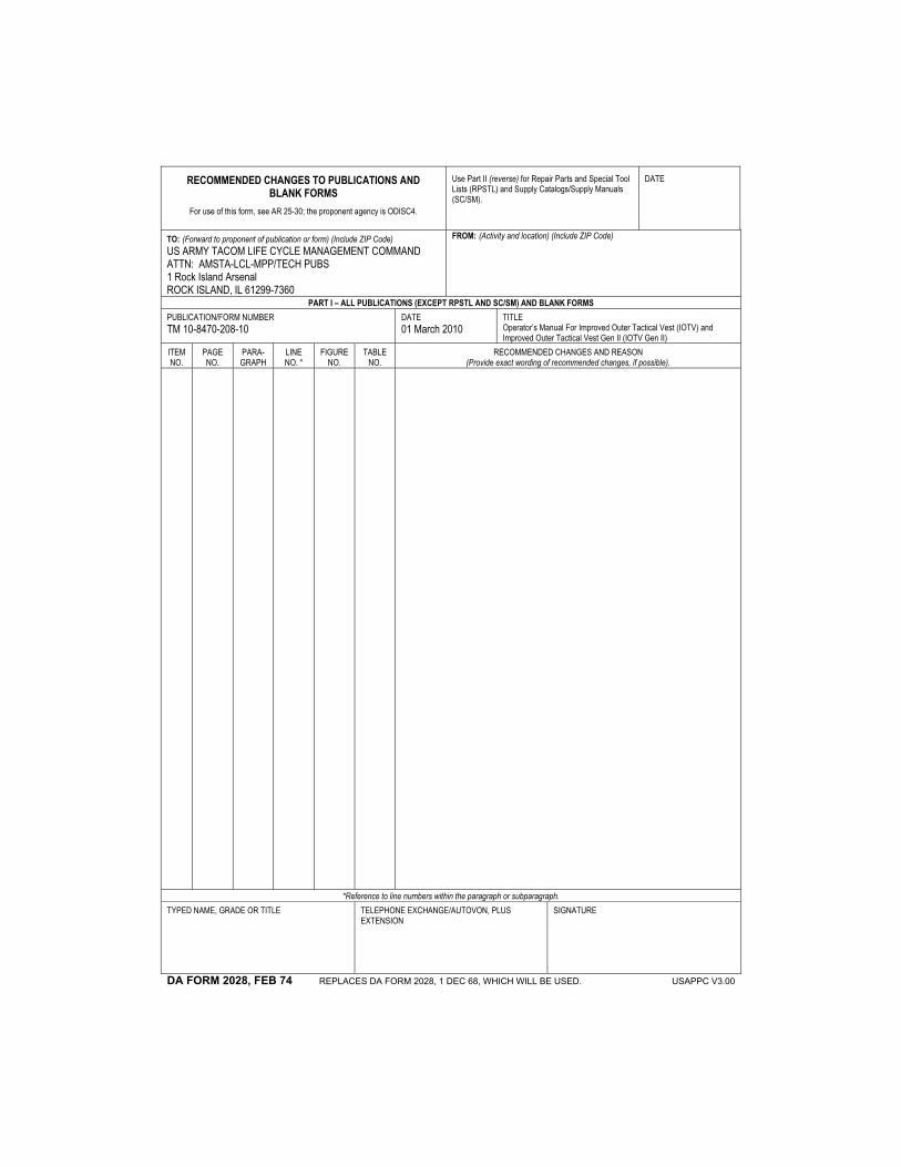
RECOMMENDED CHANGES TO PUBLICATIONS AND BLANK FORMS
For use of this form, see AR 25-30; the proponent agency is ODISC4.
Use Part II (reverse) for Repair Parts and Special Tool Lists (RPSTL) and Supply Catalogs/Supply Manuals (SC/SM).
DATE
TO: (Forward to proponent of publication or form) (Include ZIP Code) US ARMY TACOM LIFE CYCLE MANAGEMENT COMMAND ATTN: AMSTA-LCL-MPP/TECH PUBS 1 Rock Island Arsenal ROCK ISLAND, IL 61299-7360
FROM: (Activity and location) (Include ZIP Code)
PART I – ALL PUBLICATIONS (EXCEPT RPSTL AND SC/SM) AND BLANK FORMS PUBLICATION/FORM NUMBER TM 10-8470-208-10
DATE 01 March 2010
TITLE Operator’s Manual For Improved Outer Tactical Vest (IOTV) and Improved Outer Tactical Vest Gen II (IOTV Gen II)
ITEM NO.
PAGE NO.
PARA- GRAPH
LINE NO. *
FIGURE NO.
TABLE NO.
RECOMMENDED CHANGES AND REASON (Provide exact wording of recommended changes, if possible).
*Reference to line numbers within the paragraph or subparagraph. TYPED NAME, GRADE OR TITLE TELEPHONE EXCHANGE/AUTOVON, PLUS
EXTENSION SIGNATURE
DA FORM 2028, FEB 74 REPLACES DA FORM 2028, 1 DEC 68, WHICH WILL BE USED. USAPPC V3.00

TO: (Forward to proponent of publication or form) (Include ZIP Code) US ARMY TACOM LIFE CYCLE MANAGEMENT COMMAND ATTN: AMSTA-LCL-MPP/TECHPUBS 1 Rock Island Arsenal ROCK ISLAND, IL 61299-7360
FROM: (Activity and location) (Include ZIP Code) DATE
PART II – REPAIR PARTS AND SPECIAL TOOL LISTS AND SUPPLY CATALOGS/SUPPLY MANUALS PUBLICATION NUMBER TM 10-8470-208-10
DATE 01 March 2010
TITLE Operator’s Manual For Improved Outer Tactical Vest (IOTV) and Improved Outer Tactical Vest Gen II (IOTV Gen II)
PAGE NO.
COLM
NO.
LINE NO.
NATIONAL STOCK
NUMBER
REFERENCE NO.
FIGURE
NO.
ITEM NO.
TOTAL NO. OF MAJOR
ITEMS SUPPORTED
RECOMMENDED ACTION
PART III – REMARKS (Any general remarks or recommendations, or suggestions for improvement of publications and blank forms. Additional blank sheets may be used if more space is needed.)
TYPED NAME, GRADE OR TITLE TELEPHONE EXCHANGE/AUTOVON, PLUS EXTENSION SIGNATURE
UASPPC V3.00

RECOMMENDED CHANGES TO PUBLICATIONS AND BLANK FORMS
For use of this form, see AR 25-30; the proponent agency is ODISC4.
Use Part II (reverse) for Repair Parts and Special Tool Lists (RPSTL) and Supply Catalogs/Supply Manuals (SC/SM).
DATE
TO: (Forward to proponent of publication or form) (Include ZIP Code) US ARMY TACOM LIFE CYCLE MANAGEMENT COMMAND ATTN: AMSTA-LCL-MPP/TECH PUBS 1 Rock Island Arsenal ROCK ISLAND, IL 61299-7360
FROM: (Activity and location) (Include ZIP Code)
PART I – ALL PUBLICATIONS (EXCEPT RPSTL AND SC/SM) AND BLANK FORMS PUBLICATION/FORM NUMBER TM 10-8470-208-10
DATE 01 March 2010
TITLE Operator’s Manual For Improved Outer Tactical Vest (IOTV) and Improved Outer Tactical Vest Gen II (IOTV Gen II)
ITEM NO.
PAGE NO.
PARA- GRAPH
LINE NO. *
FIGURE NO.
TABLE NO.
RECOMMENDED CHANGES AND REASON (Provide exact wording of recommended changes, if possible).
*Reference to line numbers within the paragraph or subparagraph. TYPED NAME, GRADE OR TITLE TELEPHONE EXCHANGE/AUTOVON, PLUS
EXTENSION SIGNATURE
DA FORM 2028, FEB 74 REPLACES DA FORM 2028, 1 DEC 68, WHICH WILL BE USED. USAPPC V3.00
TO: (Forward to proponent of publication or form) (Include ZIP Code) US ARMY TACOM LIFE CYCLE MANAGEMENT COMMAND ATTN: AMSTA-LCL-MPP/TECHPUBS 1 Rock Island Arsenal ROCK ISLAND, IL 61299-7360
FROM: (Activity and location) (Include ZIP Code) DATE
PART II – REPAIR PARTS AND SPECIAL TOOL LISTS AND SUPPLY CATALOGS/SUPPLY MANUALS PUBLICATION NUMBER TM 10-8470-208-10
DATE 01 March 2010
TITLE Operator’s Manual For Improved Outer Tactical Vest (IOTV) and Improved Outer Tactical Vest Gen II (IOTV Gen II)
PAGE NO.
COLM
NO.
LINE NO.
NATIONAL STOCK
NUMBER
REFERENCE NO.
FIGURE
NO.
ITEM NO.
TOTAL NO. OF MAJOR
ITEMS SUPPORTED
RECOMMENDED ACTION
PART III – REMARKS (Any general remarks or recommendations, or suggestions for improvement of publications and blank forms. Additional blank sheets may be used if more space is needed.)
TYPED NAME, GRADE OR TITLE TELEPHONE EXCHANGE/AUTOVON, PLUS EXTENSION SIGNATURE
UASPPC V3.00

Distribution: To be distributed in accordance with the initial distribution number (IDN) 314252, requirements for TM 10-8470-208-10.
By Order of the Secretary of the Army:
GEORGE W. CASEY, JR. General, United States Army
Chief of Staff Official:
JOYCE E. MORROW Administrative Assistant to the
Secretary of the Army1006310
TM 10-8470-208-10


PIN: 085476-000