Embed Size (px)
Citation preview

Page
BORING SYSTEM EVOLUTION 1000
UK MACHINE CODE 17824101 MANUAL CODE 00008027 EDITION 07/2014
ORIGINAL USE AND MAINTENANCE MANUAL
ALWAYS KEEP THIS MANUAL TOGETHER WITH THE MACHINE
WOODWORKING MACHINERY

Page 2
Page intentionally left blank
Page 3
EC Declaration of Conformity
The manufacturer
Maggi Technology S.r.l.
Via delle Regioni, 299 - 50052 Certaldo (FI) ITALY
Declares that the machinery
complies with all relevant provisions of the directive:
2006/42/EC (Machine)
2004/108/EC (EMC)
and compile the technical file of the above machinery.
Adesivo targa matricola
Certaldo
The General Manager
The machinery BORING MACHINE
Model BORING SYSTEM EVOLUTION 1000

Page 4
Page intentionally left blank
Page 5
INTRODUCTION
Some information and illustrations in this manual may differ from the machine in your
possession, since all the configurations inherent in the machine complete with all the
OPTIONALS are described and illustrated. Therefore, refer only to that information
strictly connected with the machine configuration you have purchased. The
manufacturer in his pursuit of a policy of costant development and updating of the
product may make any modifications without any prior notice.
This manual has been drawn up exclusively for our customers’ use, guaranteeing that at the
date of issue it constitutes the latest update of the documentation related to use of the
product. Use of this manual is on full responsibility of the user. The manufacturer does not
grant any further guarantee for any imperfections, incompleteness and/or operating
difficulties, expressly excluding any responsibility for direct or indirect damage deriving from
use of this documentation. MAGGI TECHNOLOGY reserves the right to make any
modifications to the product described in this manual at any time without prior notice.
All reproduction rights are reserved by MAGGI TECHNOLOGY.
WE WISH TO THANK YOU FOR CHOOSING ONE OF OUR PRODUCTS
All the information, advices and important warnings for a correct use of the ma-
chine, have been inserted into this manual. This manual also contains the rules
for a correct periodical maintenance to keep this machine in perfect efficiency.
We suggest that all the chapters of this manual are thoroughly read before you
use the machine for the very first time.
Page 6
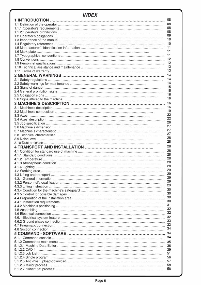
INDEX 1 INTRODUCTION …………………………………………………………………………. 1.1 Definition of the operator ………………………………………………………………………………… 1.1.1 Operator’s requirements ………………………………………………………………………………. 1.1.2 Operator’s prohibitions ………………………………………………………………………………… 1.2 Operator’s obligations …………………………………………………………………………………… 1.3 Importance of the manual ……………………………………………………………………………….. 1.4 Regulatory references ……………………………………………………………………………………. 1.5 Manufacturer’s identification information ………………………………………………………………. 1.6 Mark plate ………………………………………………………………………………………. 1.7 Typographical conventions ……………………………………………………………………………….. 1.8 Conventions ………………………………………………………………………………………………… 1.9 Personnel qualifications …………………………………………………………………………………... 1.10 Technical assistance and maintenance ……………………………………………………………. 1.11 Terms of warranty …………………………………………………………………………………….
2 GENERAL WARNINGS ……………………..………………………………………….. 2.1 Safety regulations ………………………………………………………………………………………… 2.2 Safety warnings for maintenance ………………………………………………………….. 2.3 Signs of danger ………………………………………………………………………………………… 2.4 General prohibition signs ……………………………………………………………………………….. 2.5 Obligation signs ……………………………………………………………………………………….. 2.6 Signs affixed to the machine ……………………………………………………………………..
3 MACHINE’S DESCRIPTION ……………………………………………………………. 3.1 Machine’s description …………………………………………………………………………………….. 3.2 Machine’s composition …………………………………………………………………………… 3.3 Axes ……………………………………………………………………………………………... 3.4 Axes’ description …………………………………………………………………………………………… 3.5 Job specification ………………………………………………………………………………. 3.6 Machine’s dimension ……………………………………………………………………………………... 3.7 Machine’s characteristic …………………………………………………………………………………... 3.8 Technical characteristic …………………………………………………………………………………. 3.9 Noise level ……………………………………………………………………………………... 3.10 Dust emission ………………………………………………………………………………………….
4 TRANSPORT AND INSTALLATION …………………………………………... 4.1 Condition for standard use of machine ..……………………...………………………………………… 4.1.1 Standard conditions ..……………………………………………………………………………………. 4.1.2 Temperature .……………………………………………………………………………………………... 4.1.3 Atmospheric condition …………………………………………………………………………………... 4.1.4 Lighting …….……………………………………………………………………………………………... 4.2 Working area ………………………...……………………………………………………………………. 4.3 Lifting and transport …….…………………………………………………………………………………. 4.3.1 General information ..……………………………………………………………………………………. 4.3.2 Personnel’s qualification ………………………………………………………………………………... 4.3.3 Lifting instruction ………………..……………………………………………………………………….. 4.3.4 Condition for the machine’s safeguard ………...……………………………………………………… 4.3.5 Control for possible damages …..……………………………………………………………………… 4.4 Preparation of the installation area …...………………………………………………………………….. 4.4.1 Installation requirements ...……………………………………………………………………………… 4.4.2 Machine’s positioning …………..……………………………………………………………………….. 4.5 Assembling .………………………………………………………………………………………………… 4.6 Electrical connection ...…………………………………………………………………………………….. 4.6.1 Electrical system feature ……..…………………………………………………………………………. 4.6.2 Ground phase connection ...…………………………………………………………………………….. 4.7 Pneumatic connection …...………………………………………………………………………………… 4.8 Suction connection …………………………………………………………………………………………
5 COMMAND - SOFTWARE ……………..……………………………………………….. 5.1.1 Command console ……………………………….……………………………………………………… 5.1.2 Commands main menu ………..………………………………………………………………………... 5.1.2.1 Machine Data Editor …………………………………………………………………………………. 5.1.2.2 CAD 4 ……………...………………………………………………………………………….. 5.1.2.3 Job List ……………………………………………………………………………………………….. 5.1.2.4 Single program ..…..….……………………..……………………………………………………. 5.1.2.5 Ant.-Post upload-download……………………………………………………………………………. 5.1.2.6 Mirror process ……….…...……………………………………………………………………………. 5.1.2.7 “Ribattuta” process……………………………………………………………………………………
08 08 09
08
08
11 11
10
10
11
12 12 13 13
14 14 14 15 15 16 16
16 16 19 22 22 26 27 27 27 28 28
28
28 28 28 28 28 29 29 29 29 29
30 30 30 30 31 32 32
32 33 33 34
34 34
35 36 39 51 56 57 58 58

Page 7
5.1.2.8 Shoutdown machnine……………………………………………………………………………….. 5.2 Use of the machine ……………………...………………………………………………………………… 5.2.1 Working cycle ………………………………………………………………..…………………………… 5.2.2 Emergency stop ……………………….…… …………………………………………………………… 5.2.3 Restart after emergency ………………………………...……………………………………………… 5.2.4 Further risks ..……………………………. ……………………………………………………………… 5.2.5 Operations is specific and difficult area …………………………. ……………………………………
6 MAINTEINANCE ..…………..……………………………………………………………. 6.1.1 Warning for manteinance ..………...…………………………………………………………………… 6.1.2 Operation with specific technicalskills ………………….……………………………………………… 6.1.3 Cleaning …...……………………………………………………………………………………………... 6.1.4 Periodical control ...……………………………………………………………………………………… 6.1.5 Condensate descharge ………………..……………………………………………………………….. 6.1.6 Air pressure regulation and control ……………………………………………………………………. 6.1.7 Boring head lubrication ………………...……………………………………………………………….. 6.1.8 Solid waste disposal ……….……………………………………………………………………………. 6.1.9 Liquid waste disposal …………………………………………………………………………………….
60 60 60
60
59
61 61
60
60
61
61 62 62 62
63 64 64
Page 8
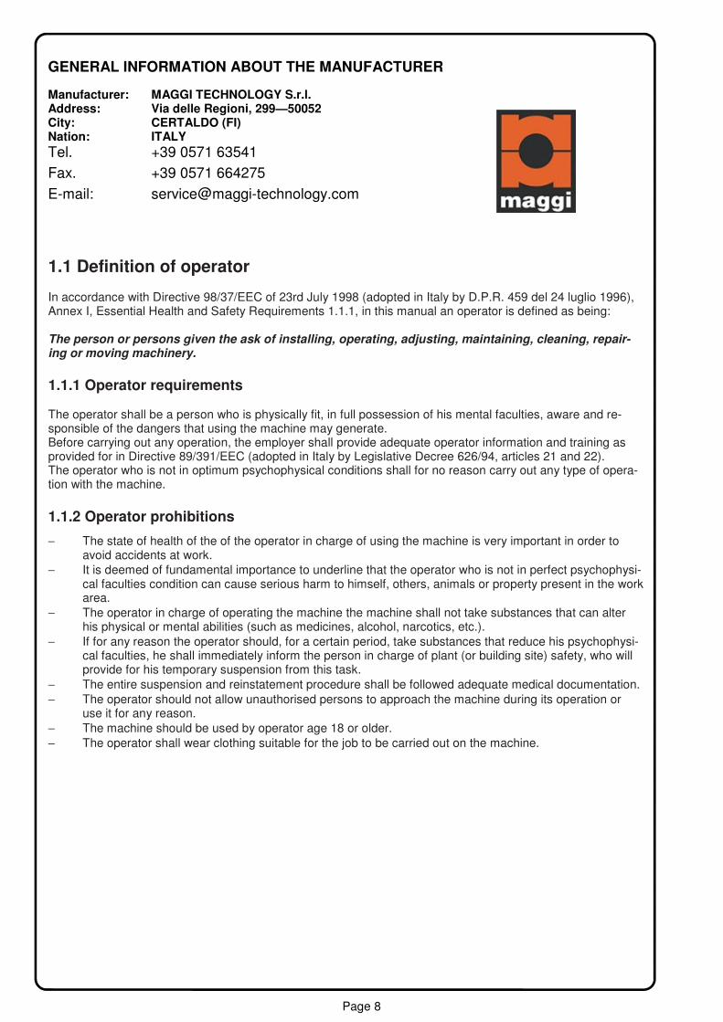
1.1 Definition of operator In accordance with Directive 98/37/EEC of 23rd July 1998 (adopted in Italy by D.P.R. 459 del 24 luglio 1996), Annex I, Essential Health and Safety Requirements 1.1.1, in this manual an operator is defined as being: The person or persons given the ask of installing, operating, adjusting, maintaining, cleaning, repair-ing or moving machinery.
1.1.1 Operator requirements The operator shall be a person who is physically fit, in full possession of his mental faculties, aware and re-sponsible of the dangers that using the machine may generate. Before carrying out any operation, the employer shall provide adequate operator information and training as provided for in Directive 89/391/EEC (adopted in Italy by Legislative Decree 626/94, articles 21 and 22). The operator who is not in optimum psychophysical conditions shall for no reason carry out any type of opera-tion with the machine.
1.1.2 Operator prohibitions
− The state of health of the of the operator in charge of using the machine is very important in order to avoid accidents at work. − It is deemed of fundamental importance to underline that the operator who is not in perfect psychophysi-
cal faculties condition can cause serious harm to himself, others, animals or property present in the work area.
− The operator in charge of operating the machine the machine shall not take substances that can alter his physical or mental abilities (such as medicines, alcohol, narcotics, etc.).
− If for any reason the operator should, for a certain period, take substances that reduce his psychophysi-cal faculties, he shall immediately inform the person in charge of plant (or building site) safety, who will provide for his temporary suspension from this task.
− The entire suspension and reinstatement procedure shall be followed adequate medical documentation. − The operator should not allow unauthorised persons to approach the machine during its operation or
use it for any reason. − The machine should be used by operator age 18 or older.
− The operator shall wear clothing suitable for the job to be carried out on the machine.
GENERAL INFORMATION ABOUT THE MANUFACTURER Manufacturer: MAGGI TECHNOLOGY S.r.l. Address: Via delle Regioni, 299—50052 City: CERTALDO (FI) Nation: ITALY
Tel. +39 0571 63541
Fax. +39 0571 664275
E-mail: [email protected]

Page 9
1.2 Operator obligations The Council Directive 12th June 1989, n°391 (adopted in Italy with Legislative Decree 19 September 1994, n.626), on the introduction of measures to encourage improvements in the safety and health of workers at work, defines the fundamental criteria regulating the behaviour of operators to prevent accidents. In particular, article 13, contained in section III of the Directive, lists the obligations of the operators and in particular: 1. It shall be the responsibility of each worker to take care as far as possible of his own safety and health
and that of other persons affected by his acts or omissions at work in accordance with is training and the instructions given by his employer.
2. To this end, workers must in particular, in accordance with their training and the instructions given by their employer:
− make correct use of machinery, apparatus, tools dangerous substances, transport equipment and other means of production;
− make correct use of the personal protective equipment supplies to them and, after use, return it its proper place;
− refrain from disconnecting, changing or removing arbitrary safety device fitted, e.g. to machinery, appara-tus, tools, plant and building, and use such safety devices correctly;
− immediately inform the employer and/or the workers with specific responsibility for the safety and health of workers of any work situation they have reasonable grounds for considering represents a serious and immediate danger to safety and health and of any shortcomings in the protection arrangements;
− cooperate, in accordance with national practice, with the employer and/or workers with specific responsi-bility for the safety and health of workers, for as long as may be necessary to enable any tasks or re-quirements imposed by the competent authority to protect the safety and health of workers at work to be carried out;
− cooperate, in accordance with national practice, with the employer and/or workers with specific responsi-bility for the safety and health of workers, for as long as may be necessary to enable the employer to insure that the working to environment and working conditions are safe and pose no risk to safety and health within their field of activity.
In compliance with what is mentioned in section II article 10, the employer shall take appropriate measures to make sure that these directives, and the related safety standards, be known and abided by. Therefore the em-ployer shall take appropriate measures so that workers and/or their representatives in the undertaking and/or establishment receive, in accordance with national laws and/or practices which may take account, the size of the undertaking and/or establishment , all that necessary information so that the safety and health of the operator are safeguarded. Therefore: This machine usage and maintenance manual shall be kept by the person in charge in an easily accessible place, in perfect state of conservation and the complete disposal of those requesting it, as long as the latter are in some way linked to the operation of the machine himself.

Page 10
1.3 Importance of the manual This manual provides information regarding the installation, use and maintenance of the machine defined: BORING SYSTEM 1000 EVOLUTION The machine shall be used in compliance with the information specified in this manual: we therefore recom-mend that be read carefully before installing and operating the machine, without neglecting any written parts and playing special attention to the highlighted messages. Observance of the regulations and recommenda-tions contained in this manual enables safe use and appropriate action. Should the machine vary from what is described herewith, the user shall inform the manufacturer before putting the machine to use. The usage and maintenance manual constitutes an integral part of the machine; it shall be kept intact and in a safe place throughout the life of the machine, even if the machine is passed on to another user.
Failure to comply with the instructions contained in this usage and maintenance manual re-lieves the manufacturer of any responsibility. For any information that is not understood or can-not be inferred from the manual, consult the manufacturer directly.
1.4 Regulatory references The following regulations were referred to during the machine designing phase and the drafting of this manual: − Presidential Decree no. 459 of 24th July 1996 - Regulations for accident prevention. − Directives 89/392/EEC, 91/368/EEC, 93/44/CEE and 93/68/EEC, on the approximation of the laws of the
Member States on machinery. − Presidential Decree no. 547 of 27th April 1995 - Regulations for accident prevention. − Law no. 791 del 18th October 1977 - Implementation of directives of the European Community Council
73/23/EEC on the safety guarantees required of electrical equipment designed for use within certain voltage limits. − Legislative Decree no. 626 of 25th November 1996 - Implementation of Directive 93/68/CEE on CE
marking of electrical equipment. − Legislative Decree no. 615 of 2nd November 1996 - Implementation of Council Directive 89/336/EEC of
3 May1989 on electromagnetic compatibility, modified by Directive 92/31/EEC of 28th April 1992 and by Directive 93/68/EEC of 22nd July 1993, and by Directive 93/97/CEE of 29th October 1993.
− CEN/TC114 - Reference EN 292 : 1991 - Safety of Machinery - Fundamental concepts; general princi-ples for design:
− Part 1a - Basic terminology and methodology EN 292-1. − Part 2a - Technical principles and specifications EN 292-2. − CEN/TC114 - Reference EN 294; 1992 - Safety distance. − CEN/TC114 - Reference EN 349; 1993 - Minimum gaps to avoid crushing of parts of the human body. − CEN/TC114 - Reference EN 418; 1992 - Emergency stop equipment. − CEN/TC114 - Reference EN 563; 1994 - Temperature of touchable surface. − UNI EN 1037: 1997 - Safety of machinery - Prevention of accidental start. − UNI EN 811: 1998 - Safety of machinery - Safety distance to prevent danger zone being reached by the
lower limbs. − UNI EN 999: 2000 - Safety of machinery - Positioning of protective equipment in respect of approach
speeds of parts of the human body. − CENLEC - reference CEI EN 60204-1; 1993 (second edition) - Electrical equipment of machinery: Part 1:
General rules. − UNI EN 1837: 2001 - Safety of machinery - Integral lighting of machinery. − CEI EN 60529-6; 1997 - Degree of protection with cover (IP Codes). − CEI EN 60439-1; 1995 - Low voltage switchgear and control gear assemblies. − CEI EN 50081-2; 1994 - Electromagnetic compatibility. − EN 55011: 1991 - Limits and methods of measurement of radio-interference. − UNI EN 983; 1992 - Safety requirements of systems and their components for pneumatic transmissions. − UNI EN 953 - Safety of machinery - General requirements for the design and construction of fixed and
movable guards. − UNI EN 954 - 1 1998 - Safety of machinery - Safety-related parts of control systems. − UNI EN 1088; 1995 - Safety of machinery - Interlocking device associated with guards. − UNI EN 1050; 1996 - Safety of machinery - Principles of risk assessment.

Page 11
1.5 Manufacturer’s identification information The identification of Maggi Technology S.r.l. as the machine manufacturer is done in compliance with the leg-islation in force by means of the following: - Identification plate - Usage and maintenance The BORING SYSTEM EVOLUTION 1000 have been designed and manufactured exclusively by: Maggi Technology S.r.l.
1.6 Mark plate The machine can be identified by the metal plate lead-sealed to the machine, containing indelible these information: - Model - Serial number - Year of construction - Name of manufacturer - Voltage (V) - Frequency (Hz) - Absorbed (KW) - Mass (Kg) A reproduction of the mark plate applied to the machine is found in the enclosures.
Do not remove the “CE MARK” plate and/or replace it with other plates belonging to same model ma-chines present in the production departments. If the “CE MARK” plate is accidentally damaged, removed from the machine or simply does not have the manufacturer’s seal, the customer shall immediately notify Maggi Engineering s.r.l. and request a replacement.
1.7 Typographical conventions
Information referring to procedures or practices which, if not carried out correctly, can cause injury, death r long-term to the health of people and the environment.
Information referring to procedure or practices witch, if not carried out correctly, can cause danger to the product.
Instructions, references, information regarding any subject of particular importance.
DANGER
CAUTION
INFORMATION
INFORMATION
Page 12
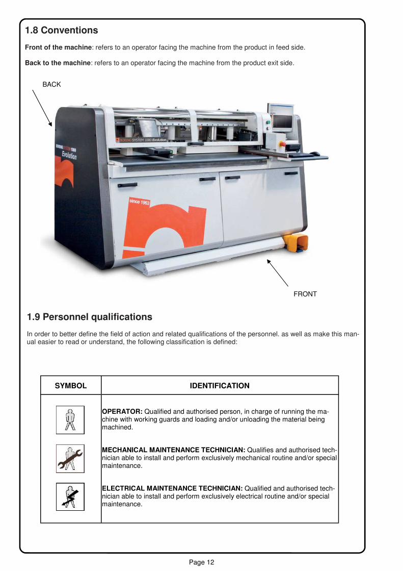
1.8 Conventions Front of the machine: refers to an operator facing the machine from the product in feed side. Back to the machine: refers to an operator facing the machine from the product exit side.
1.9 Personnel qualifications In order to better define the field of action and related qualifications of the personnel. as well as make this man-ual easier to read or understand, the following classification is defined:
FRONT
BACK
SYMBOL IDENTIFICATION
OPERATOR: Qualified and authorised person, in charge of running the ma-chine with working guards and loading and/or unloading the material being machined.
MECHANICAL MAINTENANCE TECHNICIAN: Qualifies and authorised tech-nician able to install and perform exclusively mechanical routine and/or special maintenance.
ELECTRICAL MAINTENANCE TECHNICIAN: Qualified and authorised tech-nician able to install and perform exclusively electrical routine and/or special maintenance.

Page 13
1.10 Technical assistance and mantenance Routine and special maintenance shall be performed in accordance with the instructions contained in this man-ual. For all cases not included and for any type of assistance, please contact the manufacturesr directly, sup-plying the information contained on the plate fixed to the machine: − Machine model − Serial number − Year of construction Correct reference guarantees quick and accurate answers. − If machine maintenance is not performed according to the supplied instructions, or if not original spare
parts are used without the written authorised of the manufacturer, or in any case in such a way as to jeopardise the intactness or characteristics of the machine, the manufacturer shall consider himself re-lieved of any responsibility regarding safety to people and defective operation.
− Any not authorised modification shall render the warranty void. − In case of major or complex maintenance, refer to the instruction contained in this manual. − In case of doubt, contact the machine distributor or the manufacturer in order to guarantee safety under
any circumstance. − When removing heavy or bulky parts, make sure adequate lifting equipment is available. − Secure that the tools available are suitable for use and avoid improper use of implements or tools. − Any modification altering the characteristics of the machine from the point of view of safety and risk pre-
vention shall be made exclusively by the manufacturer, who will certify compliance of the machine with all safety standards.
Therefore, any modification or maintenance that is not provided for in this document is to be considered arbi-trary. In cases in which the maintenance required is not provided for in this usage and maintenance manual, contact the machine distributor or manufacturer.
1.11 Terms of warranty Maggi Technology S.r.l. guarantees that the machine has been tested on company premises with positive results. The duration of the warranty is 12 months beginning the date of delivery. Defects due to normal wear of parts that, by nature, are subject to rapid and constant wear (e.g. gaskets, belts , brushes, fuses, etc.) are not covered by the warranty. The warranty for replaced or repaired parts ex-pires on the expiry date of the machine warranty. In addition Maggi Technology S.r.l. shall not be held responsible for machine conformity defects caused by either the failure to comply with the regulations contained in the instruction manual or improper use or care of the machine. The buyer is therefore entitled to the replacement of parts found to be defective, provided that the failures haven’t been caused by tampering and, in the case of modifications, without previous written consent from Maggi Technology S.r.l. The documentation has been drafted on the basics of the topics contained in the safety Directive and Regula-tions in force. Therefore it is absolutely necessary to read all the volumes in their entirety to obtain the best performance from the machine and guarantee a long life-span of all its parts. The configuration of some parts or devices described or illustrated in the document may differ from of the ma-chine and its specific setup developed in compliance with special needs or safety regulations. In this case some descriptions, reference or procedures may be generic, however maintaining their effectiveness. The sup-ply of special tools or implements with the machine is closely linked to the specific characteristics and the safety standards in force in each country. Dimensioned drawings and photos all provided only as examples and references for making the next easier to understand. In pursuing a policy continuous product development and updating, the company reserves the right to change both functional and aesthetic characteristics, to vary the design of any functional part or accessory, or to sus-pend production and supply, without having to inform anyone and without incurring in any obligation. In addition Maggi Technology S.r.l. reserves the right to introduce any structural or functional modifications, as well as modify the supply of spare parts and accessories without prior notice.
Page 14
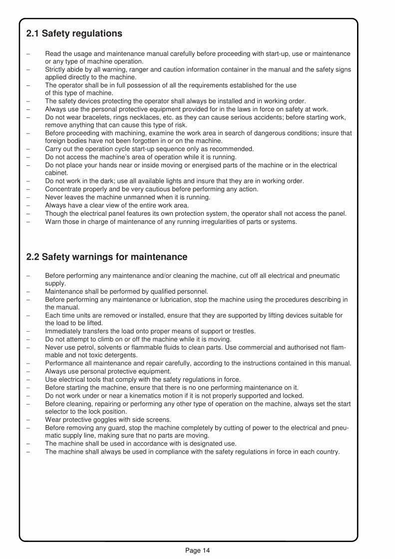
2.1 Safety regulations − Read the usage and maintenance manual carefully before proceeding with start-up, use or maintenance
or any type of machine operation. − Strictly abide by all warning, ranger and caution information container in the manual and the safety signs
applied directly to the machine. − The operator shall be in full possession of all the requirements established for the use of this type of machine. − The safety devices protecting the operator shall always be installed and in working order. − Always use the personal protective equipment provided for in the laws in force on safety at work. − Do not wear bracelets, rings necklaces, etc. as they can cause serious accidents; before starting work,
remove anything that can cause this type of risk. − Before proceeding with machining, examine the work area in search of dangerous conditions; insure that
foreign bodies have not been forgotten in or on the machine. − Carry out the operation cycle start-up sequence only as recommended. − Do not access the machine’s area of operation while it is running. − Do not place your hands near or inside moving or energised parts of the machine or in the electrical
cabinet. − Do not work in the dark; use all available lights and insure that they are in working order. − Concentrate properly and be very cautious before performing any action. − Never leaves the machine unmanned when it is running. − Always have a clear view of the entire work area. − Though the electrical panel features its own protection system, the operator shall not access the panel. − Warn those in charge of maintenance of any running irregularities of parts or systems.
2.2 Safety warnings for maintenance
− Before performing any maintenance and/or cleaning the machine, cut off all electrical and pneumatic supply.
− Maintenance shall be performed by qualified personnel. − Before performing any maintenance or lubrication, stop the machine using the procedures describing in
the manual. − Each time units are removed or installed, ensure that they are supported by lifting devices suitable for
the load to be lifted. − Immediately transfers the load onto proper means of support or trestles. − Do not attempt to climb on or off the machine while it is moving. − Never use petrol, solvents or flammable fluids to clean parts. Use commercial and authorised not flam-
mable and not toxic detergents. − Performance all maintenance and repair carefully, according to the instructions contained in this manual. − Always use personal protective equipment. − Use electrical tools that comply with the safety regulations in force. − Before starting the machine, ensure that there is no one performing maintenance on it. − Do not work under or near a kinematics motion if it is not properly supported and locked. − Before cleaning, repairing or performing any other type of operation on the machine, always set the start
selector to the lock position. − Wear protective goggles with side screens. − Before removing any guard, stop the machine completely by cutting of power to the electrical and pneu-
matic supply line, making sure that no parts are moving. − The machine shall be used in accordance with is designated use. − The machine shall always be used in compliance with the safety regulations in force in each country.
Page 15
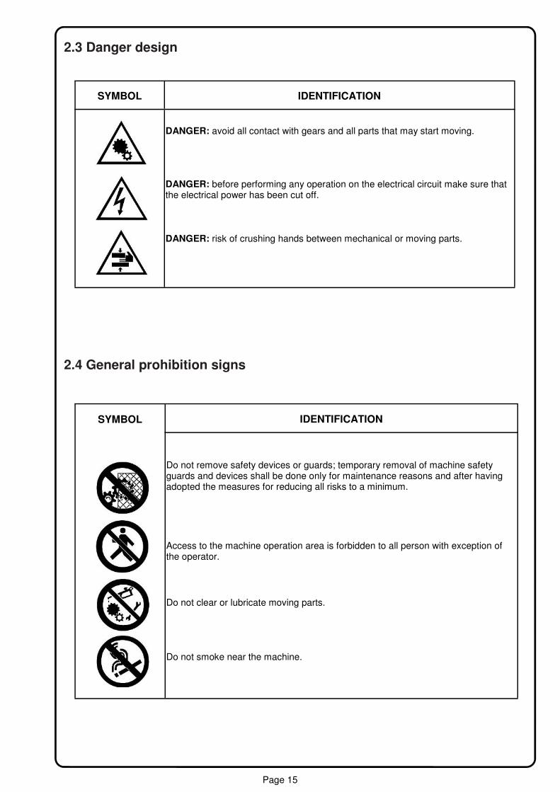
SYMBOL IDENTIFICATION
DANGER: avoid all contact with gears and all parts that may start moving.
DANGER: before performing any operation on the electrical circuit make sure that the electrical power has been cut off.
DANGER: risk of crushing hands between mechanical or moving parts.
2.3 Danger design
2.4 General prohibition signs
SYMBOL IDENTIFICATION
Do not remove safety devices or guards; temporary removal of machine safety guards and devices shall be done only for maintenance reasons and after having adopted the measures for reducing all risks to a minimum.
Access to the machine operation area is forbidden to all person with exception of the operator.
Do not clear or lubricate moving parts.
Do not smoke near the machine.

Page 16
2.5 Mandatory signs
SYMBOL IDENTIFICATION
Ensure that all guards and safety devices are in working order. Immediately report any defects or inadequacy of the protection and safety devices and any dangerous situation you become aware of.
Cut off power before connecting or disconnecting current plugs.
Work clothing must be worn.
Safety shoes must be worn.
Safety helmet must be worn.
Safety gloves must be worn.
Ear protection must be worn.
2.6 Signs affixed to the machine − Do not remove signs applied to the machine. − All sign shall be clearly legible and not covered by objects. − All damaged signs shall be replaced upon request to the manufacturer.
3.1 Machine description BORING SYSTEM EVOLUTION 1000 is designed to make per through holes or blind, in the bottom side, front, rear and side LH , panels of wood or similar, so it works the panel for 4-sides.
INFORMATION

Page 17
Advantages of boring from the bottom: − the panel’s good-face is protected from any mechanical components contact; − elimination definitely shavings from the hole; − the type of approach makes optimal automatic panel time and precision of execution; − the beginning/end of panel reading is made automatically by a laser sensor. It transfer the panel cutting
errors to the panel inward.
Below is represented the boring head configuration and its tools characteristic. Additional spindles are to be decided at the moment of purchase.
− n°11 independent Vertical spindles ( A ) − n°4+1 Horizontal heads with 1 spindles each ( B ) − n.1 Blade Ø120 thickn.4mm (max 6 mm.) ( C )
Applicable tools Types of drill bits applicable to this machine are: plane type ( D ), V-point type ( E ), hinge type ( F ) ,with chamfer , circular blade ( G ). CAM Program installed on BSE 600 classifies the different types of drill bits as follows: Drill ( D ) ; bit n.1 Plane type Drill ( E ) ; bit n.2: V-type Drill ( F ) ; bit.n.3: Hinge type
Drill ( G ) ; bit n.4 with chamfer (max Ø20).
Circular blade ( H ) ; Ø120x4 / 6mm.
INFORMATION
INFORMATION
( D ) ( E ) ( F )
DANGER The Ø35 mm drill bit can’t be fixed on n.2 spindles.
( B)
( B) ( A) ( C)
( G ) ( H )

Page 18
Working examples
Running holes under Running holes in the head ( axis x )
Running hole for hinge Running hole 4° side ( axis y )
Page 19
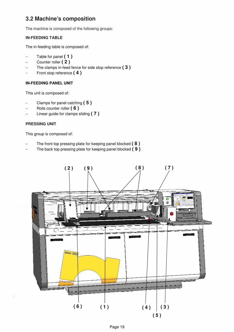
3.2 Machine’s composition The machine is composed of the following groups: IN-FEEDING TABLE The in-feeding table is composed of:
− Table for panel ( 1 ) − Counter roller ( 2 ) − The clamps in-feed fence for side stop reference ( 3 ) − Front stop reference ( 4 ) IN-FEEDING PANEL UNIT
This unit is composed of:
− Clamps for panel catching ( 5 ) − Rolls counter roller ( 6 ) − Linear guide for clamps sliding ( 7 ) PRESSING UNIT
This group is composed of:
− The front top pressing plate for keeping panel blocked ( 8 ) − The back top pressing plate for keeping panel blocked ( 9 )
( 6 ) ( 1 ) ( 4 )
( 5 )
( 3 )
( 2 ) ( 9 ) ( 8 ) ( 7 )
Page 20
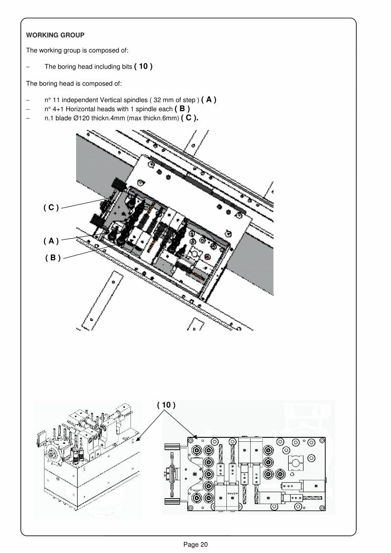
WORKING GROUP The working group is composed of:
− The boring head including bits ( 10 ) The boring head is composed of:
− n° 11 independent Vertical spindles ( 32 mm of step ) ( A ) − n° 4+1 Horizontal heads with 1 spindle each ( B ) − n.1 blade Ø120 thickn.4mm (max thickn.6mm) ( C ).
( B )
( 10 )
( C )
( A )

Page 21
CONTROL UNIT Control unit includes: the computer containing the software for the management of controlled axes and of graphical programming, the approach of the working group; the console that includes the screen and keyboard, a ground plane. Board includes: -Machine integrated control panel.Industrial PC Model Microsipu , Windows XP , developed by CNI , 15” color monitor , CD , keyboard,mouse. Software ILENIA , CAD-CAM4.
Pneumatic pedal for working process start.
Page 22
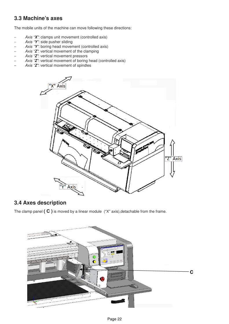
3.3 Machine’s axes The mobile units of the machine can move following these directions: − Axis “X”: clamps unit movement (controlled axis) − Axis “Y”: side pusher sliding − Axis “Y”: boring head movement (controlled axis) − Axis “Z”: vertical movement of the clamping − Axis “Z”: vertical movement pressors − Axis “Z”: vertical movement of boring head (controlled axis) − Axis “Z”: vertical movement of spindles
3.4 Axes description
The clamp panel ( C ) is moved by a linear module (“X” axis),detachable from the frame.
C

Page 23
The side pusher sliding (axis “Y”) is manual after unlocking it by the button ( D ) pressing.
The boring head sliding (axis “Y”) is moved by a balls screw powered by a gear motor ( E ).
( E )
Gear motor
Balls screw
D

Page 24
( F )
The closure of the clamp (axis “z”) is by a pneumatic cylinders ( F ).
The clamps, holding the wooden panel during the boring cycle ( axis “z”),are put into motion by n.2+2 pneu-
matic cylinders. ( G ).
( G )

Page 25
Vertical movement of boring head, for panel drilling from the bottom (axis “Z”),
is powered by a gear motor ( H )
Upstroke of spindles (axis “Z”) is powered by a ball screw ( I )
( H )
( I )

Page 26
3.5 Job specification STANDARD USE The machine BORING SYSTEM EVOLUTION 1000 have been developed for drilling panel from the bottom.
The machine is equiped with safety guards and shields providing full protection to the operator and preventing any damage to the used tools during the working cycle. The standard use needs cautions. Please pay attention to: − mechanic, electric and pneumatic regulation of units during the working process; − removal of mechanic, electric and pneumatic safety device during the working process; − repair mechanic, electric and pneumatic parts when machine is working; − machine’s working process when the cover of the electronic console is open; − machine’s working when body’s covers are open and security device has been tampered. These use, not removable by the constructor, are not allowed.
Different uses from the one declared by the constructor are not allowed. Before shipment, every machine passes through many tests and detailed controls. With a correct standard use and normal maintenance, every machine ensures reliability and long life.
The machine must be used only by the one operator, working near console and in-feeding area. NOT AUTHORIZED USE Every use not included in STANDARD USE as not allowed and in particular: − connecting machine to electric source different from the foreseen ones; − using machine with safety device damaged or tampered; − using the commercial device for purposes different from the ones allowed by the constructor; − getting on the machine to make maintenance and using equipment not included in standard ones; − working panels of material and dimensions not allowed by constructor.
It’s not allowed to use machine for purposes different from the standard ones.
INFORMATION
DANGER
INFORMATION
DANGER

Page 27
3.7 Machine’s characteristic
The panel are usually of wood or similar material. The panel dimension are: − Minimum panel length ( mm ) = 300 − Maximum panel length (mm ) = 3200 − Minimum panel width ( mm ) = 120 − Maximum panel width ( mm ) = 1020 − Minimum panel thickness ( mm ) = 08 − Maximum panel thickness ( mm ) = 40 − Width min. / max. with blade Ø120 thickn.4 (max thickn.6 mm) = 143 / 1000. − Side 4° drill dimension min. / max.(mm) = 18 / 1000.
3.8 Technical characteristic − Supply voltage ( V ) = 220 / 400 − Network frequency ( Hz ) = 50/60 − Total power installed ( Kw ) = 3,0 − Spindles rotation speed ( rpm ) = 3200 − Panel feeding speed ( m/min ) = (25 “X” axis , at work). − Boring head speed ( m/min ) = 42 (all axis not in work). − Maximum tool’s diameter ( mm ) = Ø35 − Maximum tool’s length ( mm ) = 77 − Boring range ( mm ) = 1020 − Air pressure required ( Bar ) = 6/7 − Air consumption 10 litres for cycle (reference 30 litres for minutes). − Boring head dust extraction ( mm ) = Ø60 x 2 pos.
INFORMATION
INFORMATION
3.6 Machine’s dimension Length A ( mm ) = 2200 Width B ( mm ) = 1300 Height C ( mm ) = 1250
Page 28
3.9 Noise level Noise test ISO 3746 (UNI 7712) gave the following results: − Average noise emission in vacuum ............ Lp < 70 [dB (A)]. − Average noise emission in operation ……... Lp = 82 [dB (A)].
3.10 Dust emission Values of dust emissions in normal using condition, with the machine connected to an efficient suction system that guarantees to the outlet a minimum speed of 20 m/sec., are always within the limits established by the in force rule of 2 mg/m3.
The machine has to be installed by well-trained and duly informed operators, knowing and taking all
necessary measures to carry out safe installation procedures. Furthermore we wish to remind that all
tools involved in the installation procedures have to be in perfect conditions and used for the right pur-
poses as per indications of the manufacturer. The operator has to know all relevant safety laws and
rules in matters of wood-working machines and the related working area, so as to protect himself and
other people from possible work injuries.
.
4.1 Condition for standard use of machine 4.1.1 Standard condition The machine has to work indoor, with a controlled, with low humidity and dust expositions. Different conditions can damage the machine, decrease quality of product and be dangerous for the operators. If the conditions are not good, it’s very important to adopt solutions to have standard ones.
4.1.2 Temperature Minimum ambient temperature.....................................5° C Maximum ambient temperature.................................+40° C
4.1.3 Atmospheric condition Machine’s electronic system works perfectly in atmospheric conditions with umidity 50% at 40° C and umidity 90% with a temperature till a 20° C (without condensate).
4.1.4 Lighting The machine has not a proper light. Lighting of working area is very important for operator’s safety and quality of work. Minimum lighting to ensure the reading of display, symbols and marks (about 300 lux). Maximum lighting has not to dazzling the operator.
Lighting level need to be enough to guarantee safety during working process. During maintenance in area with no good light, it is obligatory to use a portable unit to brighten specific dark area
DANGER
DANGER

Page 29
4.2 Working area Keep aisles for the operators and make sure that they are appropriate so as to assure a safe use and mainte-nance. Before placing the machine make sure of keeping a free area available all around the machine itself, which has to be not smaller than 1500mm in all directions. Choosing the most appropriate place to set up Your working area is very important in order to create high-quality work conditions in terms of safety, maintenance of the machine etc. Make sure that Your working area is well lit and airy. Make sure that the normal working activi-ties and the environmental conditions of the workplace are not obstacles for the free access to the machine drives, especially to safety devices. The carrying-out of all operation and maintenance activities has to be en-sured in any case.
4.3 Lifting and transport 4.3.1 General information Carriage and installation have to be done by well-trained and qualified working-staff and according to the indica-tions stated in this chapter. The machine is wrapped in a plastic film, giving protection during the transit, and in consideration of the final destination and kind of transport it can be packed either into a wooden box or just fixed on a pallet.
Possible “DANGER ZONES” between the place of unloading and the predisposed installation area have to be previously detected and defined.
Electrical cables and/or pipes conveying high-temperature liquids and high-pressure gases lying be-tween the place of unloading and the predisposed installation area of the machine HAVE TO BE de-tected and insulated in compliance with local regulations and laws, moreover any possible electrical retention HAS TO BE previously detected and removed
4.3.2 Personnel’s qualification The unloading of the machine has to be done by a qualified working-staff well-trained in the usage of fork-lift
trucks.
The over-mentioned operations have to be carried out with the greatest care, by means of the suitable unloading facilities and inside the predisposed areas. Make sure that no people is exposed when carrying out the lifting and unloading operations, and prevent any-
body from walking under or close to the machine while being carried to the designated area.
4.3.3 Lifting instruction
While carrying the machine to the designated area always keep it at a minimum height from the ground
so as to ensure the greatest loading stability and the optimal viewing conditions for the driver in order
to prevent any possible collision.
CAUTION
CAUTION
CAUTION
DANGER

Page 30
CAUTION
CAUTION
DANGER
Only use fork-lift trucks having the suited carrying capacity and suited fork length. It is very important to avoid any collision during the whole loading and carrying procedure and to keep the machine always in balance.
Make sure that the forks of the lift truck are well positioned under the machine, so that its centre of gravity is
well balanced, thus ensuring the greatest stability of the whole loading.
An unbalanced load create dangerous conditions which persist during the whole carrying procedure
4.3.4 Conditions for the machine’s safeguard All parts subject to rust and corrosion are adequately protected against oxidation and atmospheric agents by protective greasing and spraying. Having to keep the machine stored for a short time make sure that the de-signed location is free from humidity and that the packaging is undamaged and well dry. Under particular stor-age conditions, for example storage inside a container, You have to make sure that the container is adequately protected against atmospheric agents such as rain, snow and hail and that access is allowed to authorized personnel only. Having to keep the machine stored for a longer time it is necessary to undertake further protective measures
such as the greasing of all bearings and tooled parts
4.3.5 Control for possible damages
On receipt of the machine You are requested to check it in order to detect possible damages. Before unpacking the machine make sure that there are no spares or accessories fixed to the cartons and boxes just to avoid damaging them.
4.4 Preparation of the installation area The machine is designed to stand on its small feet. The installation area has to be equipped with pneumatic
and electrical connection points.
Before installing the machine make sure that the floor carrying capacity is suited to the purpose. Do verify that there are no electrical cables nor water pipes lying across the assigned area.
4.4.1 Installation requirements The machine installation has to be carried out on a flat surface having the suited carrying capacity. It is essen-
tial that the installation floor is well leveled - maximum allowed and non cumulative error is + 0,25 mm / m
( even by using risers), ruling gradient allowed up to + 0,3 % in all directions.
CAUTION

Page 31
4.4.2 Machine’s postioning
The machine is designed to stand on its own small feet.
The working area, on which the machine is positioned, has to respond to all requirements stated by the machine
developers at the planning stage. The minimum required working space is also to be considered in order to en-
sure easy and safe operation and maintenance.
For the leveling You need a delicate level ( 0,05 mm/m accuracy) and a rectified angle
plate (+/- 0,01 mm).
INFORMATION
INFORMATION
After having positioned the machine on the assigned area, do start leveling by following the below-stated in-structions:
− Take off the filling caps ( A ) − Work on adjusting screws for leveling ( B ) − Put the angle plate on the working-table, and
lay the level on the plate length- and longwise to check leveling.
CAUTION
Make sure that leveling is carried out with the greatest accuracy, in fact a bad positioning and leveling
may result into abnormal wear conditions of some mechanical parts and into malfunctioning.
( A )
( B ) ( B )

Page 32
4.5 Assembling
Keep all the facilities used for the placing and carrying of the machine in order to have them available
for future positioning. The machine is already assembled; only electrical and pneumatic connections
are needed to start working.
4.6 Electrical connection
The electrical connection of the machine to the power point has to be done only by using the supplied
plug (type 3P+T16A).
4.6.1 Electrical system feature
Before switching on the machine make sure that the voltage is the right
one by checking electrical data stated
on the machine plate.
Do not switch on the machine before having checked the compliance with following electrical require-
ments : possible damages caused by a wrong electrical connection or voltage are not covered by war-
ranty.
The electric system quality has to respect the CEI norms 60204-1, IEC 204-1 (unless otherwise agreed with the customer): − Voltage (see picture) with tolerance + 10%. − Voltage‘s frequency with tolerance + 2%. − Maximum power required (see picture). − Harmonic distortion: from the2nd to the 5th < 10%, from the 6th to the 30th <2%. − Lack of balance in 3 phase power supply: <2%.
INFORMATION
CAUTION
INFORMATION
PLUG TYPE 3 P + T 16A
CAUTION

Page 33
− In direct machine’s protection are TN type, so it doesn’t need any other caution. If connection is different (TT, IT) or if norms require other protection please provide it taking in consideration:
− Electromagnetic interference precaution can product high frequency electric dissipations. − Machine can have direct current discharges to the earth. − The differential switch must resist to high tension of atmospheric rise (EN 61008-1) and test with pulse
8/20 µs > 1000A (VDE 0432 T2). − Recommended switch SIEMENS 5SZ3466-0KG00 o 5SZ6466-0KG00 following SIEMENS instruction or
other device with the same characteristics. − For connection tension <= 400 V, electric cabinet is equipped with an automatic isolator for short circuit till
10 KA R.M.S or pick of 17 KA. − For connection tension > 415 V, automatic isolator can resist tension of short circuit till 4 KA; − If short circuit tension is higher, it must e decreased.
If there are disturbs of electric net it’s very important to install a magnetic filter. If disturbs are more than 10% please install a voltage stabilizer.
4.6.2 Ground phase connection The grounding of all metal parts of the machine is safely ensured by insulated conductors connected to the
earth bar inside the switch board. The grounding has to be in compliance with CEI 64-8 normative.
All materials used for the grounding have to be in compliance with the relevant normative and the con-
nections have to be adequately protected.
Make sure that the raceway is as short as possible and that the earth conductors are not subjected to mechani-
cal stress nor to oxidation.
4.7 Pneumatic connection Provide pneumatic connection of FRL group, positioning on the base. − The pneumatic connection has to be done by joining the compressed-air pipe of the pneumatic plant to
the connection of the pneumatic group on the machine by means of a hose clip or pipe fitting. − Pull knob ( A ) till its locking (about 5 mm) to take pressure in the pneumatic plant. − Turn till the manometer ( B ) shows 6 /7 bar. − At the end regulation press knob ( A ) to stop the rotation. − During working process, check and ad just pressure if necessary.
CAUTION
INFORMATION
( A )
( B )

Page 34
4.8 Suction connection
A dust collection plant is meant to ensure the good functioning and performance of the machine, for this reason
the machine has always to be connected to a dust collection plant during the working process. The machine
has two chip collecting drawers, removable on the sides (see fig.) that connect the suction pipe system.
BORING SYSTEM EVOLUTION 1000 don’t need any regulation.
The next paragraphs are about tool’s replacement.
It’s high recommended, before any tool’s replacement, to turn off the electric and pneumatic connec-tion and wear protections during maintenance, like boots, gloves, protective goggles etc..
5.1 Command 5.1.1Command console On the board there are following commands:
− Switch with light ( 1 ) − Electric line light ( 2 ) − Emergency stop ( 3 ) − USB port (universal serial bus) ( 4 )
CAUTION
INFORMATION
DANGER
( 1 )
( 2 )
( 3 )
( 4 )
-SYSTEM : Industrial PC mod.Microsipu , Windows XP ,
developed by CNI . Color Monitor 15”with CD ,
USB,keyboard ,mouse. Software ILENIA CAD-CAM4.

Page 35
5.1.2 Commands main menu
The system is visible on a monitor 15 "TFT ILENIA software and related management icons . When you start the system automatically starts the program management JOB LIST. After loading the machine needs to reset the axes "ZERO SETTING".
———————————————————————————————————————————————— Alternatively, or in other screen being set to zero the axes can also be obtained with the commands listed be-low . Axis START then , finally executed command the LEDs "zero setting", all become green and the car is ready to work.
————————————————————————————————————————————————- The first thing to do is to configure the tool magazine and then the installation of the tools. Select " Manual" from the menu bar . Open the other drop down menu and select " Machine Data Editor" to enter into man-agement tools
INFORMATION
( ZERO SETTING )
( JOB LIST )
( Manual )
( Axis ) ( LED )
( Machine Data Editor )
Page 36
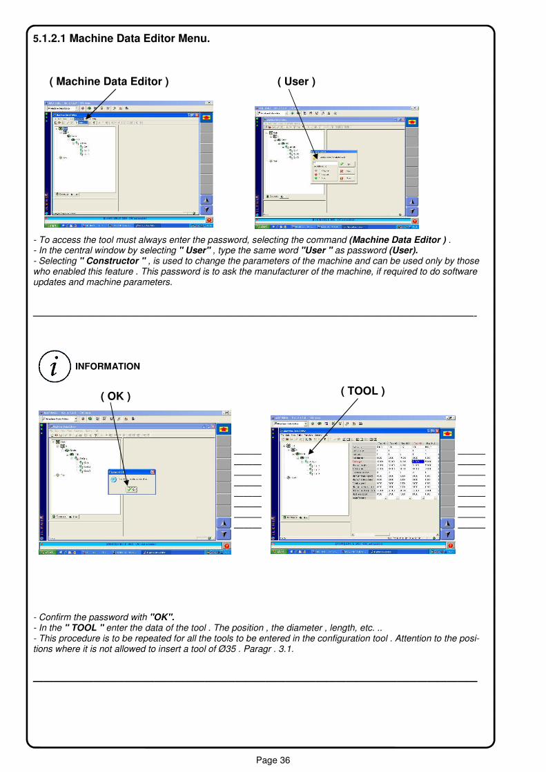
5.1.2.1 Machine Data Editor Menu.
- To access the tool must always enter the password, selecting the command (Machine Data Editor ) . - In the central window by selecting " User" , type the same word "User " as password (User). - Selecting " Constructor " , is used to change the parameters of the machine and can be used only by those who enabled this feature . This password is to ask the manufacturer of the machine, if required to do software updates and machine parameters.
————————————————————————————————————————-
——— —————— —————— —————— —————— —————— —————— —————— ———
- Confirm the password with "OK". - In the " TOOL " enter the data of the tool . The position , the diameter , length, etc. .. - This procedure is to be repeated for all the tools to be entered in the configuration tool . Attention to the posi-tions where it is not allowed to insert a tool of Ø35 . Paragr . 3.1.
————————————————————————————————————————————
INFORMATION
( OK )
( Machine Data Editor ) ( User )
( TOOL )

Page 37
- Select only the " Pack 1" to access the screen of the tool head . Do not use normally configurations " CONF.2 and 3 ."
—————————————————————————————————————————————————-
- The configuration of the head is visible as a whole and to the right you can see the data table utensils.
- "Graphic tooling ."
( Conf.1 )
INFORMATION

Page 38
( Remove / Insert Tool )
- In the configuration screen head can intervene to change tools "Remove / Insert Tool" .
——————————————————————————————————————————————
- In the figure above you can see the data of the ' selected tool . This serves to control and for changes to be made.
INFORMATION

Page 39
5.1.2.2 CAD-4 Ambient / . Programmation panel process.
( CAD / 4) - From the main menu you can enter nell'ambinte " CAD / 4 " to create machining programs modificace panels . Full reference see " Manual CAD / 4 .
———————————————————————————————————————————————-
- Home Screen " CAD / 4" , with preset icons to Macro (drilling, excavation ) . - With the command " New " opens a new page where you can schedule the work to be performed on pannelllo.
( New )

Page 40
- First data to be entered is the size of "Dimensions " of the panel to work . If you exceed the possible working on the machine activates an error message .
———————————————————————————————————————————————-
View of the " zero side " of the panel and at the bottom left is shown the geometric reference to the departure of the shares , according to the coordinate axes. The joke " Pin X = Ø " is inserted by means of the pneumatic pedal . The angle indicated " Ref Point X and Y = Ø = Ø " , is the departure of the measures.
( Dimensions )
INFORMATION
Pin X = Ø
Ref.Point X = Ø Y = Ø
Page 41
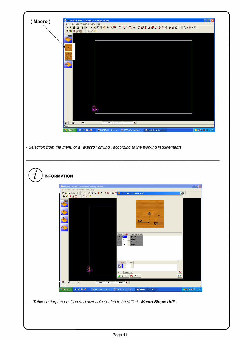
- Selection from the menu of a "Macro" drilling , according to the working requirements .
————————————————————————————————————————————————
- Table setting the position and size hole / holes to be drilled . Macro Single drill .
( Macro )
INFORMATION

Page 42
(Tool selection) - Command to select the type of tool "Tool selection" , suitable for machining (drilling and / or excavation ) .
—————————————————————————————————————————————————
(Tool Type) -- Select the desired tool "Tool type" , for working set.
Page 43
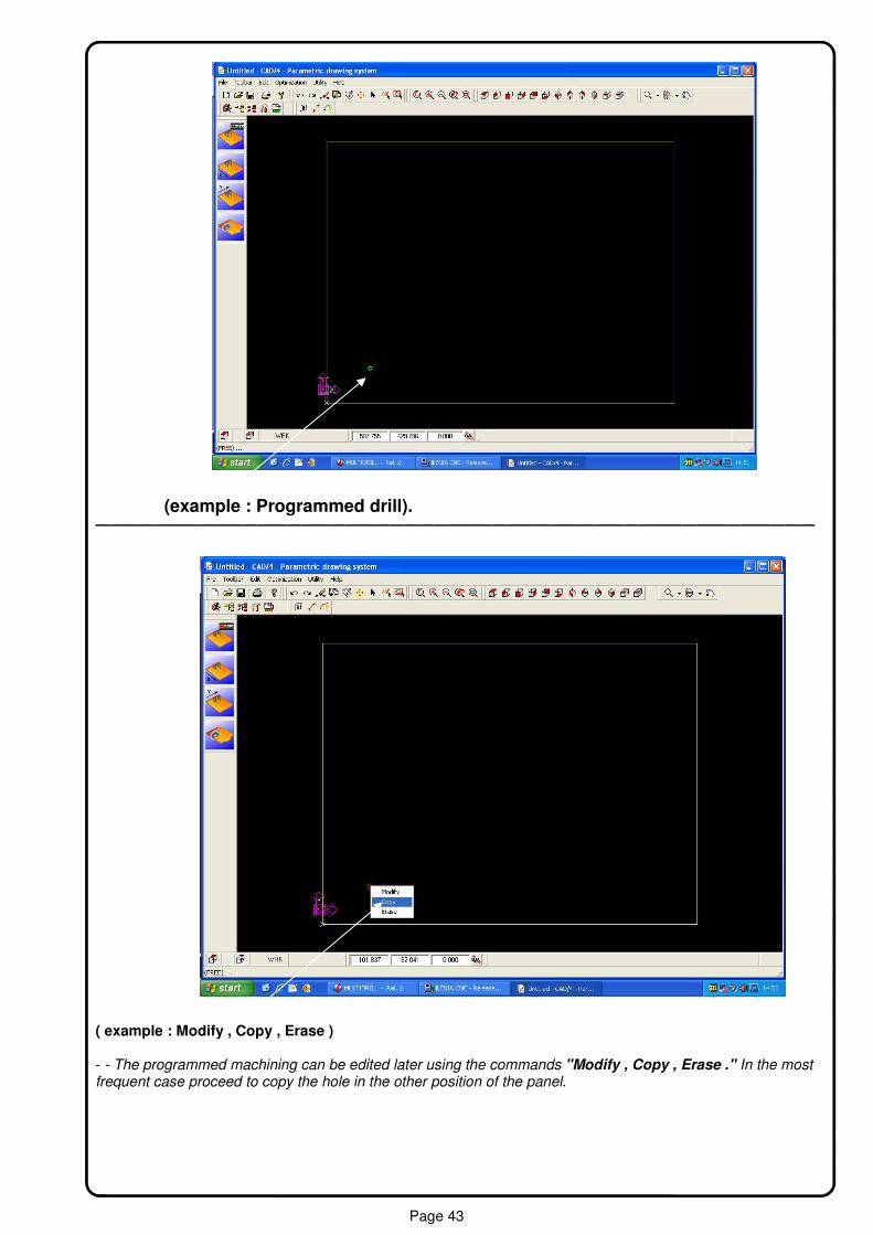
(example : Programmed drill). —————————————————————————————————————————————————
( example : Modify , Copy , Erase ) - - The programmed machining can be edited later using the commands "Modify , Copy , Erase ." In the most frequent case proceed to copy the hole in the other position of the panel.

Page 44
- Example of the hole to be copied "Selected drill copy" .
————————————————————————————————————————————————
- Position of the hole on the corner copied reported 1. "Drill position - Corner 1 reference".
( Selected drill to copy )- Corner 2 reference
( Drill position - Corner 1 reference)

Page 45
- Position of the hole reportedly copied the corner 3 . " Corner 3 reference - Drill position" .
————————————————————————————————————————————————— - Position of the hole reportedly copied corner 4 . " Corner 4 reference - Drill position" .
( Corner 3 reference - Drill position)
( Corner 4 reference - Drill position)

Page 46
————————————————————————————————————————- - Example of machining on the sides of the panel, showing the position of the Cartesian axes which changes depending on the side panel , see selection . "View side 1".
Example : ( View side zero with drill)
Page 47
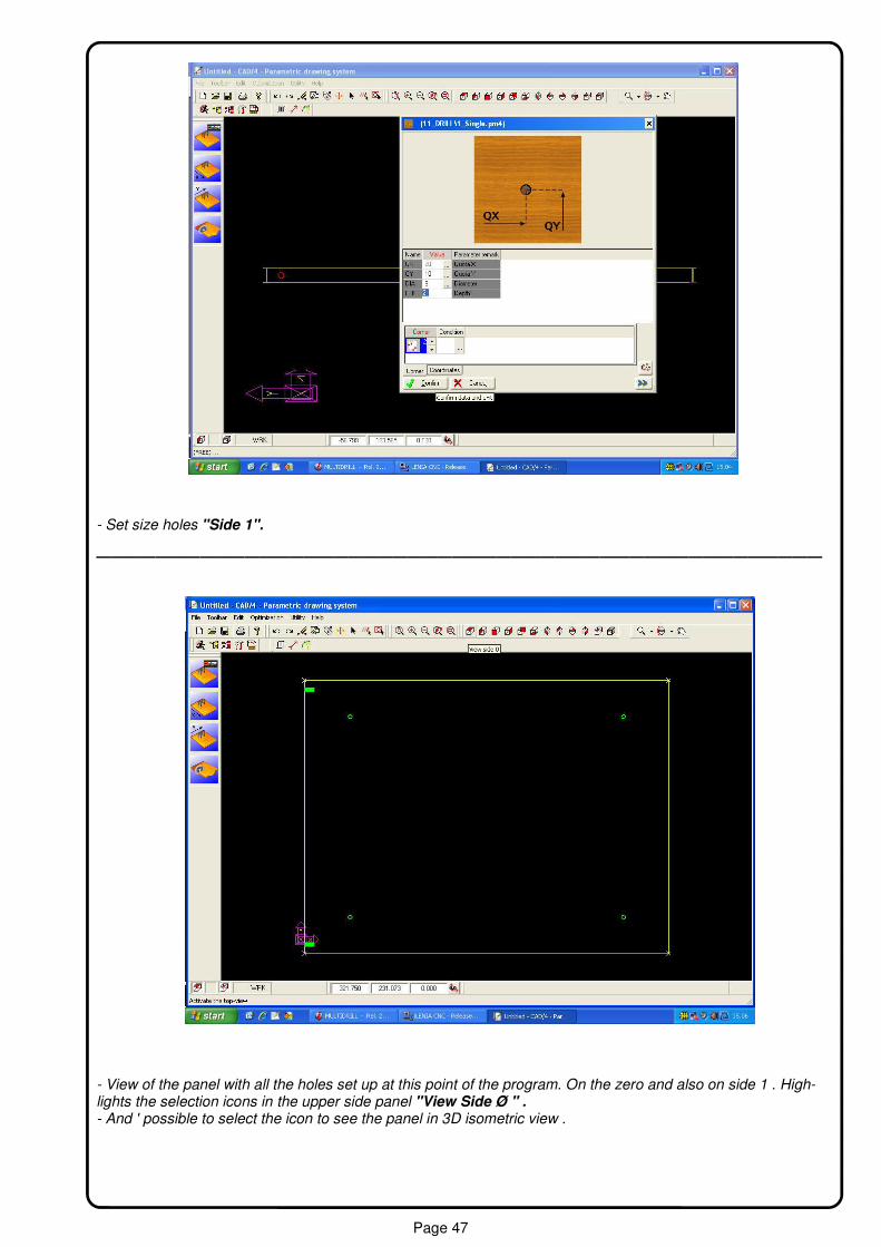
- Set size holes "Side 1".
————————————————————————————————————————————————— - View of the panel with all the holes set up at this point of the program. On the zero and also on side 1 . High-lights the selection icons in the upper side panel "View Side Ø " . - And ' possible to select the icon to see the panel in 3D isometric view .

Page 48
− Example of side 3 " Side 3 " . Note the position of the axes that change position depending on the cho-
sen side of the panel .
- Example setting " Corner 1" side 3 , panel and data processing .

Page 49
- View panel with work planned by side zero "side Ø " .
- Window for saving the "Save As " , the program of the panel cutout. Automatically opens the folder to save programs and should be given an identifying name to the program to be saved.

Page 50
- To finalize the rescue of the program created , you must select the command " Optimizer" , which performs diagnostics on the application spectrum , based on the parameters in the machine , and then rewrites inside the machine language program (ISO). The central window of the screen displays the processing and errors in writ-ing or setting.
- The window above the "Diagnostic Application" , indicates in red , any programming errors and / or those processes that the machine can not do , according to his ability dimensional or otherwise related to the ma-chine parameters preset by the manufacturer .
( Optimizer )
Page 51
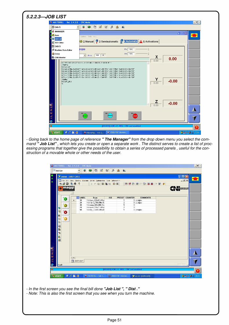
5.2.2.3—JOB LIST
- Going back to the home page of reference " The Manager" from the drop down menu you select the com-mand " Job List" , which lets you create or open a separate work . The distinct serves to create a list of proc-essing programs that together give the possibility to obtain a series of processed panels , useful for the con-struction of a movable whole or other needs of the user.
- In the first screen you see the final bill done "Job List ", " Dist ." - Note: This is also the first screen that you see when you turn the machine.

Page 52
- I f you select the command " New Job list" , you start creating a new list .
- To enter the machining programs , select the command in the window "Select Source"
( New Joblist )
( Select Souce )

Page 53
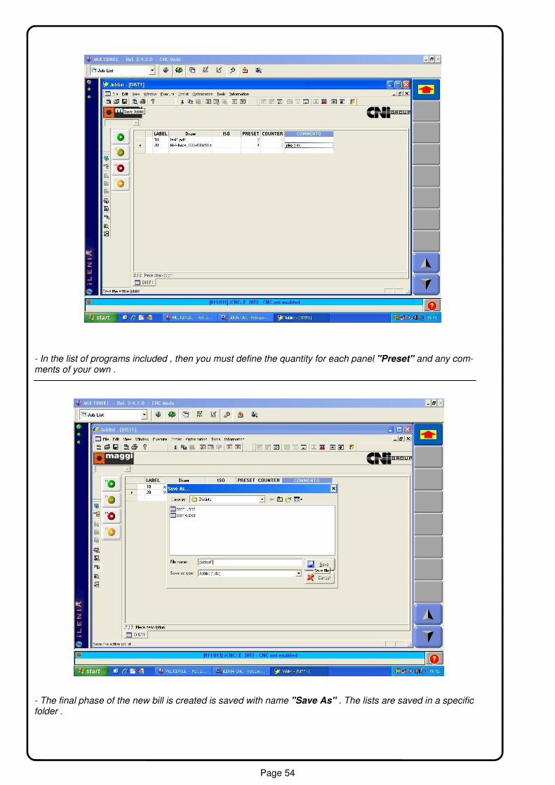
- In the selection of the program to enter "Programs explorer" , the preview panel chosen, the working set.
- The selected program is then created in the new bill . Using the same procedure you can enter other pro-grams.
( Programs explorer )
Page 54
- In the list of programs included , then you must define the quantity for each panel "Preset" and any com-ments of your own .
- The final phase of the new bill is created is saved with name "Save As" . The lists are saved in a specific folder .

Page 55
- To carry out the work of a distinguished selected, press the indicated key . "F2 - green botton ." The bar of the bill in question will be colored in red and the machine will prompt you the first panel visible in the job list .
- Example list of panels in the selected list . " Label" , 10/ 20/30 / etc. - The machine starts working from the first panel in the list.
( F2 Green Botton )
( Label )
Page 56
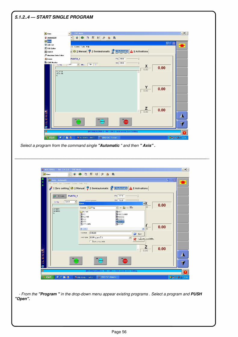
5.1.2..4 — START SINGLE PROGRAM
Select a program from the command single "Automatic " and then " Axis" .
————————————————————————————————————————————————--
- From the "Program " in the drop-down menu appear existing programs . Select a program and PUSH "Open".

Page 57
5.2.2.5 - OPTION PANEL SHUTDOWN FRONTSIDE / BACKSIDE .
− - In the standard setting , at the end of the processing cycle , the machine shows the panel toward the opera-tor , ie exhaust front "Front Download" . - To have the drain back "Back Download", press the button at the top right .
- With option "Back Download " enabled. Processing cycle at the end of the panel will be unloaded from the rear of the machine. This command is activated and / or deactivated at any time .
( Front Download)
( Back Download)
Page 58
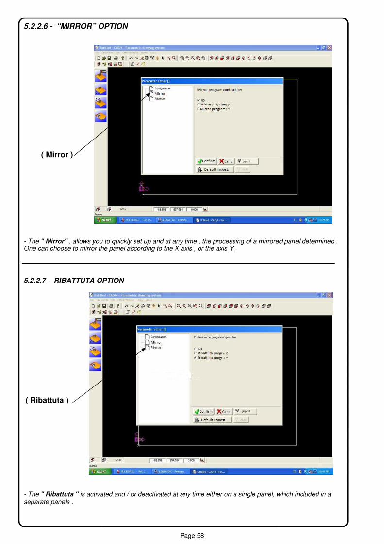
5.2.2.6 - “MIRROR” OPTION
- The " Mirror" , allows you to quickly set up and at any time , the processing of a mirrored panel determined . One can choose to mirror the panel according to the X axis , or the axis Y.
- The " Ribattuta " is activated and / or deactivated at any time either on a single panel, which included in a separate panels .
( Mirror )
5.2.2.7 - RIBATTUTA OPTION
( Ribattuta )

Page 59
5.1.2.8 - SHUTDOWN MACHINE
Window - standard Windows XP option " Turn Off Computer "
- Command “Shutdown ILENIA”
- Command “Ok”

Page 60
5.2 Use of the machine _ 5.2.1 Duty Cycle To begin a cycle of work 's operator initially must : - 1 - Select an application or a separate work . - 2 - Press the icon "Start" button on schermo.Il green (A) , lights up and flashes. - 3 - Pedal ( B). The reference pin (C) , the X-axis , "Stop Up" rises from the floor and the clamp is open. - 4- Enter the panel comparing it to the beat of DX (D) , and forward to the pin "Stop Up." - 5 - panel Set in juxtaposition to the group controrulliera (E) , acting on the pneumatic handle . - 6 (B) - Press the electric foot , to close the clamp and bring down the joke reference to "stop down" - 7 - Press selector green ( A) , to start the drilling cycle.
5.2.2 Emergency stop Facing an emergency situation press the emergency button to stop the machine 5.2.3. Restart after emergency stop To restart the machine after the emergency stop just follow the below-stated procedure: − Turn the emergency button counter-clockwise to unlock the machine − Press the green button on the control panel to restart the machine 5.2.4. Residual risk BORING SYSTEM EVOLUTION 1000 has been designed so as to minimize the need for manual intervention. To reduce the residual risk the machine has been equipped with the following safety devices: - Passive safety devices such as: fixed guards and covers protecting the access to the working components of
( Start )
( Stop Up ) Ref. X axis
( C )
( B )
( A )
( D )
( E )

Page 61
− Active safety devices such as: emergency buttons and microswitches to stop the working cycle. The machine has been equipped with some fixed barriers to minimize the residual risk arising from working parts and/or related to the misfunctioning of some mechanical components. It is possible that the operator in charge for installation and periodical maintenance is sometimes required to access the segregated areas inside the machine and to work very close to dangerous mechanical and electrical components and to working parts; in this case we recommend that the operator also use individual safety devices and take the greatest care.
During installation and /or maintenance operations always disconnect power plug and air supply
5.2.5 Segregated areas All areas inside the machine subjected to extraordinary maintenance operations, to be carried out by qualified operators only, are to be considered as segregated areas. The personnel in charge for such maintenance ope-rations has to take all safety measures in order to minimize the residual risk. A periodical and accurate maintenance is the essential condition to ensure longlasting efficiency and high reliability of the machine. It is advisable that the below-stated maintenance operations are carried out with the greatest care and accuracy.
6.1 Maintenance All maintenance operations are to be carried out by qualified personnel only, which is also supposed to have knowledge of all relevant rules and normatives about health and safety matter at the workplace.
6.1.1 Warnings It is compulsory to disconnect power plugs and air supply before carrying out periodical or extraordinary mainte-nance procedure so as to use individual safety devices such as: appropriate working suite, safety glasses etc. When carrying out maintenance operations always refer to this instruction manual. Turn to the manufacturer before carrying out maintenance operations, that are not included in this manual.
6.1.2 Technical competence required for maintenance
Machine-cleaning is to be carried out by the operator daily.
Mechanical and electrical servicing is to be carried out by qualified personnel only
At the beginning of every section, referring to the different maintenance operations, a graphic symbol is used to identify the required competence.
6.1.3 Cleaning
CAUTION
CAUTION
DAILY

Page 62
the machine
To avoid misfunctionings and fire risk You are recommended to carry-out a daily cleaning of the machine com-ponents by using compressed air.
Do not use abrasive products such as: petrol or solvent, as they would eventually damage painting, cable boots etc.
Before carrying out any maintenance operation You have to make sure that the power plug is discon-nected and the machine is stopped.
6.1.4 Check-up
The following components are to be maintained periodically:
− Safe devices − Sensors − Microswitches − Emergency buttons
6.1.5 Condensate removal from pneumatic system
The condensate level must not exceed the max.value indicated on the air drum. The exceeding condensate can be removed and conveied into a 6/4 diameter flexible pipe with direct connection to a drain cock.
6.1.6 Check and regulation of the air pressure Upgrade working-pressure by turning the regulating knob clockwise.Use lubricating grease of the following kinds: FD22 and HG 32. Verify that the rate of the air flow is not lower than the indicated minimum working rate. Set the oil injection by turning the corresponding knob, so that a drop of oil is injected every 300-600 air litres. After having pressurized the pneu-matic plant, oil can be added in through the corresponding filling hole: make sure that the maximum oil level is not exceeded. To open the ntake valve press and turn the corresponding knob clock-wise. To close the valve and remove the condensate just turn the corresponding knob coun-ter-clockwise.
CAUTION
CAUTION
DAILY
EVERY 40 HOURS USE
CAUTION
Page 63
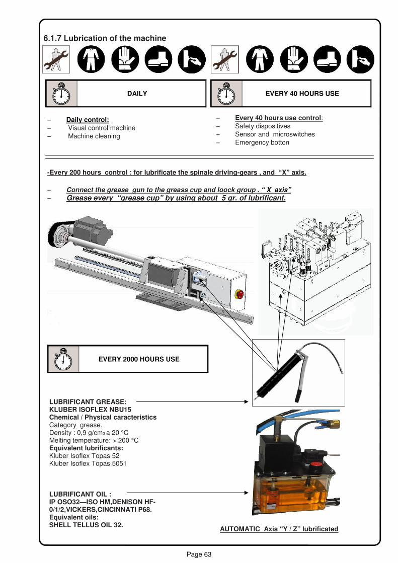
6.1.7 Lubrication of the machine
EVERY 40 HOURS USE
LUBRIFICANT GREASE: KLUBER ISOFLEX NBU15 Chemical / Physical caracteristics Category grease. Density : 0,9 g/cm3 a 20 °C Melting temperature: > 200 °C Equivalent lubrificants: Kluber Isoflex Topas 52 Kluber Isoflex Topas 5051 LUBRIFICANT OIL : IP OSO32—ISO HM,DENISON HF- 0/1/2,VICKERS,CINCINNATI P68. Equivalent oils: SHELL TELLUS OIL 32.
AUTOMATIC Axis “Y / Z” lubrificated
EVERY 2000 HOURS USE
− Daily control:
− Visual control machine − Machine cleaning
− Every 40 hours use control: − Safety dispositives − Sensor and microswitches − Emergency botton
-Every 200 hours control : for lubrificate the spinale driving-gears , and “X” axis.
− Connect the grease gun to the greass cup and loock group . “ X axis”
− Grease every “grease cup” by using about 5 gr. of lubrificant.
DAILY
Page 64
6.1.8 Machine dismantling For machine dismantling follow the below-stated instructions:
− Get a written permission from the dismantling company − Disconnect power plugs and air supply − Destroy identification plates and documents
Separate non-metallic components and give them to the appropriate re cycling companies
Do not substitute worn-out components with re cycled components, in this case Maggi Te-chnology does not take any responsibility for the possible misfunctioning of the machine.
6.1.9 Lubricants disposal For lubricants disposal follow the below-stated instructions: − Empty the grease cups − Clean the grease residues, that may have formed on the machine guides, by using a cloth − Give collected lubricants to the appropriate re cycling companies for disposal
Make sure that lubricants are disposed properly. Maggi Technology Srl does not take any responsibility for environmental damages caused by inappropriate dismantling.
Inappropriate disposal of the lubricants or of other substances used for the working activities not abiding by the laws and rules in matter of dismantling may result into: − Environmental pollution − Poisoning of the operators carrying out the disposal
DANGER
CAUTION
CAUTION
DANGER

Page 65
Page intentionally left blank

Page 66
Maggi Technology Via delle Regioni, 299
Woodworking machinery 50052 Certaldo ( Fi ) Italia
Tel. +39 0571 63541
Fax. +39 0571 664275
Development by MAGGI TECHNOLOGY