Embed Size (px)
Citation preview

PR 30-HVS
Operating Instructions en
*0000000*
0000
000
1

2
3 4
5 6

7 8
9

10 11
12
13 14
15
16
17
ORIGINAL OPERATING INSTRUCTIONS
PR 30‑HVS rotating laser
It is essential that the operating instructionsare read before the tool is operated for thefirst time.Always keep these operating instructions to-gether with the tool.Ensure that the operating instructions arewith the tool when it is given to other persons.
Contents Page1 General information 22 Description 23 Accessories 54 Technical data 55 Safety instructions 76 Before use 97 Operation 108 Care and maintenance 149 Troubleshooting 1510 Disposal 1611 Manufacturer’s warranty - tools 1712 FCC statement (applicable in US) / IC
statement (applicable in Canada) 17
1 These numbers refer to the corresponding illustra-tions. The illustrations can be found on the fold-out coverpages. Keep these pages open while studying the oper-ating instructions.In these operating instructions, the designation “the tool”or “the rotating laser” always refers to the PR 30-HVS.The designation “remote control / laser receiver” alwaysrefers to the PRA 30 (03).
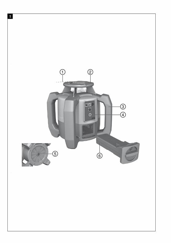
Rotating laser 1
@Laser beam (plane of rotation)
;Rotating head
=Grip
%Control panel
&Battery compartment
(Base plate with ⁵/₈" thread
)PRA 84 Li‑ion battery
+Charging activity LED
§Catch
/Charging cord socket
Rotating laser control panel 2
@On/off button
;Auto-leveling LED
=LED arrow for electronic inclination alignment
%Electronic inclination alignment button (only in con-junction with inclined plane mode)
&Shock warning function button and LED
(Inclined plane mode button and LED
)Surveillance mode LED (only with automatic verticalalignment)
+Battery charge status LED
PRA 30 control panel 4
@On/off button
;Inclination entry button “Plus” / direction button“Right” (with the PRA 90: “Up”)
=Units button
%Volume button
&Inclination entry button “Minus” / direction button“Left” (with the PRA 90: “Down”)
(Button for automatic alignment / vertical surveil-lance mode (double click)
)Receiving window
+Marking notch
§Display
PRA 30 display 5
@Display showing the position of the receiver relativeto the height of the laser plane
;Battery status
=Volume
%Display showing the distance of the receiver fromthe laser plane
en
1
>1/4s
1 General information1.1 Safety notices and their meaningDANGERDraws attention to imminent danger that will lead toserious bodily injury or fatality.
WARNINGDraws attention to a potentially dangerous situation thatcould lead to serious personal injury or fatality.
CAUTIONDraws attention to a potentially dangerous situation thatcould lead to slight personal injury or damage to theequipment or other property.
NOTEDraws attention to an instruction or other useful informa-tion.
1.2 Explanation of the pictograms and otherinformation
Symbols
Read theoperatinginstructionsbefore use.
Generalwarning
Warning:caustic
substances
Warning:electricity
For indooruse only
Return wastematerial forrecycling.
Do not lookinto thebeam.
On the tool
Laser class 2 according to EN 60825:2008
On the tool
Laser Class II according to CFR 21, § 1040 (FDA)
Location of identification data on the toolThe type designation and serial number can be found onthe type identification plate on the tool. Make a note ofthis data in your operating instructions and always referto it when making an enquiry to your Hilti representativeor service department.
Type:
Generation: 01
Serial no.:
2 Description2.1 Use of the product as directedThe Hilti PR 30-HVS is a rotating laser tool with a visible rotating laser beam and a reference beam set at 90° to themain beam. The PR 30-HVS can be used for alignment in the vertical, horizontal and inclined planes.The tool is designed to be used to determine, transfer and check levels, verticals, slopes and right angles. Examples ofits uses are: transferring datums and height marks, determining right angles for walls, vertical alignment on referencepoints and setting out slopes.The tool is designed for professional use and may be operated, serviced and maintained only by trained, authorizedpersonnel. This personnel must be informed of any special hazards that may be encountered. The tool and its ancillaryequipment may present hazards when used incorrectly by untrained personnel or when used not as directed.Hilti supplies various accessories which allow the tool to be used with maximum efficiency.To avoid the risk of injury, use only genuine Hilti accessories and insert tools.Observe the information printed in the operating instructions concerning operation, care and maintenance.Take the influences of the surrounding area into account. Do not use the appliance where there is a risk of fire orexplosion.Modification of the tool is not permissible.
en
2
2.2 FeaturesThe tool makes it possible for a single person to level or align in any plane quickly and with great accuracy.The tool levels itself automatically after switching on. The laser beam is emitted only when the specified accuracy hasbeen achieved.LEDs indicate the current operating status.The tool is powered by a rechargeable Li‑ion battery which can be charged while the tool is in operation.
2.3 PRA 30 combined remote control and laser receiverThe PRA 30 is a combined remote control unit and laser receiver. It can be used to control the PR 30-HVS rotatinglaser over great distances. The PRA 30 also serves as a laser receiver and can thus be used to detect and indicate thelaser beam at great distance.
2.4 Digital distance measurement displayThe PRA 30 displays digitally the distance between the laser plane and the marking notch on the PRA 30. This allowsthe user to determine the exact position of the receiver relative to the laser plane, with millimeter accuracy, in a singleoperation.
2.5 Automatic alignment and surveillanceUsing the PR 30-HVS and the PRA 30, a single person can align the laser plane automatically with a certain pointwith great accuracy. The tool detects the applicable alignment (horizontal, inclined or vertical) automatically and usesthe automatic alignment function accordingly (horizontal with the PRA 90 plus inclination) or automatic alignment withsubsequent monitoring of the plane (vertical). With the aid of the PRA 30, the surveillance function checks alignmentof the laser plane at regular intervals in order to avoid possible deviations due to temperature fluctuations, wind orsimilar. The surveillance function can be deactivated.
2.6 Digital inclination display with patented electronic inclination alignmentThe digital inclination display is capable of indicating an inclination of up to 21.3% when the PR 30-HVS is operating ininclined mode. This makes it possible to set out and check slopes without having to make any calculations. Electronicinclination alignment allows optimum inclination accuracy.
2.7 Shock warningThe shock warning function is activated one minute after the tool has leveled itself after switching on. The waiting timeof one minute begins again if a button is pressed within this first minute. The tool switches to warning mode if it isbrought out of level while in operation (due to vibration or an impact); all LEDs begin to blink and the laser switchesoff (the head stops rotating).
2.8 Automatic cut-outThe laser does not switch on and all LEDs blink if the tool is set up outside its self-leveling range (±5°) or if movementis blocked mechanically.The tool can be set up on a tripod with a 5/8" thread or stood directly on some other steady surface (free of vibration).When automatic leveling is activated for one or both axes, the built-in servo system ensures that the specified accuracyis maintained. The tool switches itself off when automatic leveling cannot be achieved (tool set up outside its levelingrange or physical impediment of the mechanism) or when knocked off level (see “Shock warning” section).
NOTEIf the correct level cannot be achieved, the laser switches itself off and all LEDs blink.
2.9 Items supplied1 PR 30-HVS rotating laser1 PRA 30 remote control unit / laser receiver1 PRA 80/PRA 83 receiver holder1 Operating instructions2 Manufacturer’s certificates1 PRA 84 Li‑ion battery1 PUA 81 AC adapter
en
3
1 Hilti toolbox2 Batteries (size AA cells)
2.10 Operating status indicatorsThe tool is equipped with the following operating status indicators: Auto-leveling LED, battery status LED, shockwarning function LED, inclined plane mode LED, monitoring LED and electronic alignment LED.
2.11 LED indicatorsAuto-leveling LED The green LED blinks. The tool is in the leveling phase.
The green LED lights con-stantly.
The tool has leveled itself / is operatingnormally.
Shock warning LED The orange LED lights con-stantly.
The shock warning function is deacti-vated.
Inclined plane mode LED The orange LED blinks. Alignment in the sloping plane.The orange LED lights con-stantly.
Slope mode is active.
Surveillance mode LED The orange LED lights con-stantly.
The tool is in surveillance mode. Align-ment with the reference point (PRA 30)is correct.
The orange LED blinks. The tool is aligning the laser plane withthe reference point (PRA 30).
Electronic inclination alignment LED The orange LED arrows blink. The tool is in electronic inclination align-ment mode, the PRA 30 receives nolaser beam.
Both orange LED arrows lightconstantly.
The tool is correctly aligned with thePRA 30.
The orange LED arrow on theleft lights
The tool must be rotated in a clockwisedirection.
The orange LED arrow on theright lights
The tool must be rotated in a counter-clockwise direction.
All LEDs All LEDs blink The tool has been bumped, knocked offlevel or is exhibiting some error.
2.12 Charge status of the Li‑ion battery during operation
LEDs light constantly LEDs blink Charge status CLED 1,2,3,4 - C ≧ 75 %LED 1,2,3 - 50 % ≦ C < 75 %LED 1,2 - 25 % ≦ C < 50 %LED 1 - 10 % ≦ C < 25 %- LED 1 C < 10 %
2.13 Charge status of the Li‑ion battery during charging while inserted in the tool
LEDs light constantly LEDs blink Charge status CLED 1, 2, 3, 4LED 1, 2, 3LED 1, 2LED 1-
en
4

2.14 Charge status of the Li‑ion battery during charging while not inserted in the toolIf the red LED lights constantly, the battery is being charged.If the red LED doesn’t light, the battery is either fully charged or the charger is not plugged in to the electric supply..
3 AccessoriesDesignation Short designationRemote control unit / laser receiver PRA 30 (03)Laser receiver PRA 20 (02)Receiver holder PRA 80Receiver holder PRA 83Height transfer device PRA 81Slope adapter PRA 79AC adapter PUA 81Car charging connector PUA 82Battery PRA 84Battery PRA 84GVertical angle PRA 770Batter board adapter PRA 750Batter board receiver holder PRA 751Facade adapter PRA 760Tripod PUA 20Crank tripod (elevator tripod) PA 921Crank tripod (elevator tripod) PUA 30Automatic tripod PRA 90Telescopic staffs PUA 50, PUA 55
4 Technical dataRight of technical changes reserved.
PR 30-HVSReceiving range (diameter) With PRA 30 (typical): 2…600 m (6.56…1,968.5 ft)Range of remote control (circle diameter) With PRA 30 (typical): 0…150 m (0…492.13 ft)Accuracy 1 at 10 m: ± 0.75 mmPlumb beam Continuous, perpendicular to the plane of rotationLaser class Class 2, 620-690 nm; < 1 mW (EN 60825-1:2007 / IEC
60825-1:2007); Class II (CFR 21 § 1040 (FDA)); Maxi-mum power < 4.85 mW at ≧ 300 r.p.m.
Speed of rotation 600/min, 1,000/minInclination range With the tool pre-inclined: ≤ 21.3%Self-leveling range ±5°Power supply 7.2 V / 4.5 Ah Li‑ion batteryBattery life Temperature +25°C (+77 °F), Li‑ion battery: ≥ 25 h1 Influences such as particularly high temperature fluctuations, dampness, shock, dropping, etc. can affect accuracy. Unless statedotherwise, the tool was adjusted or calibrated under standard ambient conditions (MIL-STD-810G).
en
5

Operating temperature -20…+50°C (−4…+122 °F)Storage temperature (dry) -25…+60°C (−13…+140 °F)Protection class IP 66 (in accordance with IEC 60529); Not in “charging
during operation” modeTripod thread ⁵⁄₈" x 18Weight (incl. PRA 84) 2.5 kg (5.51 lb)Dimensions (L x W x H) 200 mm (7.87") x 200 mm (7.87") x 230 mm (9.06")Drop test height From a tripod onto flat concrete: 1.5 m (4.92 ft)1 Influences such as particularly high temperature fluctuations, dampness, shock, dropping, etc. can affect accuracy. Unless statedotherwise, the tool was adjusted or calibrated under standard ambient conditions (MIL-STD-810G).
PRA 30Detection range (area diameter) Typical distance with PR 30-HVS: 2…600 m (6.56…
1,968.5 ft)Signal tone generator 3 volume levels plus mute settingLiquid-crystal display On both sidesIndicator range, distance from zero -52…52 mm (−2.05…2.05")Laser plane display range ± 0.5 mmLength of the receiving window 120 mm (4.72")Casing top edge center indicator 75 mm (2.95")Marking notches On both sidesTime without detection before automatic power off 15 minDimensions (L × W × H) 160 mm (6.3") × 67 × 24Weight (including batteries) 0.25 kg (0.55 lb)Power source 2 AA batteriesBattery life (alkaline) Temperature +20°C (+68 °F): Approx. 40 h (depends on
battery quality)Operating temperature range -20…+50°C (−4…+122 °F)Storage temperature range -25…+60°C (−13…+140 °F)Protection class IP 66 (in accordance with IEC 60529), except battery
compartmentDrop test height In the PRA 83 receiver holder, falling onto flat concrete
from the telescopic staff: 3 m (9.84 ft)
PRA 84 Li‑ion batteryRated voltage (normal mode) 7.2 VMaximum voltage (during operation or during chargingwhile in operation)
13 V
Rated current 180 mACharging time Temperature +32°C (+90 °F): 2 h 10 min (battery 80%
charged)Operating temperature range -20…+50°C (−4…+122 °F)Storage temperature range (dry) -25…+60°C (−13…+140 °F)Charging temperature range (also for charging duringoperation)
+0…+40°C (+32…+104 °F)
Weight 0.3 kg (0.66 lb)Dimensions (L x W x H) 160 mm (6.3") x 45 mm (1.77") x 36 mm (1.42")
en
6

PUA 81 AC adapterAC supply 115…230 VAC frequency 47…63 HzRated power 36 WRated voltage 12 VOperating temperature range +0…+40°C (+32…+104 °F)Storage temperature range (dry) -25…+60°C (−13…+140 °F)Weight 0.23 kg (0.51 lb)Dimensions (L x W x H) 110 mm (4.33") x 50 mm (1.97") x 32 mm (1.26")
5 Safety instructions5.1 Basic information concerning safetyIn addition to the information relevant to safety givenin each of the sections of these operating instructions,the following points must be strictly observed at alltimes.
5.2 General safety rules
a) Do not render safety devices ineffective and donot remove information and warning notices.
b) Stay alert, watchwhat you are doing and use com-mon sense when operating the machine. Don’tuse the machine when you are tired or under theinfluence of drugs, alcohol or medication. A mo-ment of inattention while operating machines mayresult in serious personal injury.
c) Keep laser tools out of reach of children.d) Failure to follow the correct procedures when open-
ing the tool may cause emission of laser radiation inexcess of class 2 or, respectively, class 3. Have thetool repaired only at a Hilti service center.
e) Do not operate the tool in explosive atmospheres,such as in the presence of flammable liquids,gases or dust. Tools and appliances create sparkswhich may ignite the dust or fumes.
f) (Statement in accordance with FCC §15.21):Changes or modifications not expressly approvedby the manufacturer can void the user’s authority tooperate the equipment.
g) Use of setting-up / adjusting devices and equipmentor operating procedures other than those specified inthese instructionsmay lead to exposure to hazardousradiation.
h) Check the condition of the tool before use. If thetool is found to be damaged, have it repaired at aHilti service center.
i) Maintain the machine carefully. Check for mis-alignment or binding of moving parts, breakageof parts and any other condition that may affectthe machine’s operation. If damaged, have the
machine repaired before use. Poor maintenance isthe cause of many accidents.
j) The user must check the accuracy of the toolafter it has been dropped or subjected to othermechanical stresses.
k) Check the tool before using it for important mea-suring work.
l) Check the accuracy of the measurements severaltimes during use of the tool.
m) When the tool is brought into a warm environmentfrom very cold conditions, or vice-versa, allow itto become acclimatized before use.
n) If mounting on an adapter, check that the tool isscrewed on securely.
o) Keep the laser exit aperture clean to avoid mea-surement errors.
p) Although the tool is designed for the tough con-ditions of jobsite use, as with other optical andelectronic instruments (e.g. binoculars, specta-cles, cameras) it should be treated with care.
q) Although the tool is protected to prevent entryof dampness, it should be wiped dry each timebefore being put away in its transport container.
r) Keep the electrical contacts dry (protect from rainor dampness).
s) Use the AC adapter only for connecting to the ACsupply.
t) Check to ensure that the tool and AC adapter donot present an obstacle that could lead to a riskof tripping and personal injury.
u) Ensure that the workplace is well lit.v) Check the condition of the extension cord and
replace it if damage is found. Do not touch the ACadapter if the extension cord or AC adapter aredamaged while working. Disconnect the supplycord plug from the power outlet. Damaged supplycords or extension cords present a risk of electricshock.
w) Avoid body contact with earthed or groundedsurfaces such as pipes, radiators, ranges andrefrigerators. There is an increased risk of electricshock if your body is earthed or grounded.
x) Do not expose the supply cord to heat, oil or sharpedges.
en
7

y) Never operate the AC adapter when it is dirty orwet. Dust (especially dust from conductive ma-terials) or dampness adhering to the surface ofthe AC adapter may, under unfavorable condi-tions, lead to electric shock. Dirty or dusty toolsshould thus be checked at a Hilti Service Centerat regular intervals, especially if used frequentlyfor working on conductive materials.
z) Avoid touching the contacts.
5.2.1 Battery tool use and care
a) Do not expose batteries to high temperatures orfire. This presents a risk of explosion.
b) Do not disassemble, squash or incinerate bat-teries and do not subject them to temperaturesover 80°C (176°F). A risk of fire, explosion or in-jury through contact with caustic substances mayotherwise result.
c) Avoid ingress of moisture. Moisture may cause ashort circuit resulting in a risk of burning injury or fire.
d) Under abusive conditions, liquid may leak from thebattery. Avoid contact. If contact accidentally oc-curs, flush with water. In the event of the liquidcoming into contact with the eyes, rinse the eyeswith plenty of water and consult a doctor. Liquidejected from the batterymay cause irritation or burns.
e) Do not use batteries other than those approvedfor use with the applicable tool or appliance. Useof other batteries or use of the battery for purposesfor which it is not intended presents a risk of fire andexplosion.
f) Observe the special instructions applicable to thetransport, storage and use of Li-ion batteries.
g) When not in use, keep the battery and the chargeraway from paper clips, coins, keys, nails, screwsor other small metal objects that could cause ashort circuit at the battery terminals or the charg-ing contacts. A short circuit at the battery terminalsor charging contacts could result in personal injury(burns) or fire.
h) Avoid short-circuiting the battery.Before insertingthe battery in the tool, check that the terminals ofthe battery and the tool are free from foreign objects.Short-circuiting the battery terminals presents a riskof fire, explosion or contact with caustic substances.
i) Do not charge or continue to use damaged bat-teries (e.g. batteries with cracks, broken parts,bent or pushed-in and/or pulled-out contacts).
j) Use only the PUA 81 AC adapter, PUA 82 motorvehicle power adapter or other chargers recom-mended by the manufacturer to power the tool orcharge the battery. Failure to observe these pointsmay result in damage to the tool. Use of a charger
with batteries other than the specific type(s) for whichit is designed presents a risk of fire.
5.3 Proper organization of the work areaa) Secure the area in which you are working and
take care to avoid directing the beam towardsother persons or towards yourself when settingup the tool.
b) Avoid unfavorable body positions when workingfrom ladders. Make sure you work from a safestance and stay in balance at all times.
c) Readings taken in the vicinity of reflective objects orsurfaces, through panes of glass or similar materialsmay produce incorrect results.
d) Ensure that the tool is set up on a steady, levelsurface (not subject to vibration).
e) Use the tool only within its specified limits.f) Make sure that your PR 30-HVS is responding only
to your PRA 30 and not to other PRA 30s that maybe in use on the jobsite.
g) When working in “charging during operation”mode, attach the mains adapter in a secure posi-tion, e.g. on a tripod.
h) When working in “charging during operation”mode, attach the AC adapter in a secure posi-tion, e.g. on a tripod.
i) Use of products for applications different from thoseintended could result in hazardous situations. Usethe product and its accessories etc. in accor-dance with these instructions and in the mannerintended for the particular type of product. Takethe working conditions and the work to be per-formed into account.
j) Use of the telescopic staff in the vicinity of over-head high voltage cables is not permissible.
5.3.1 Electromagnetic compatibilityAlthough the tool complies with the strict requirementsof the applicable directives, Hilti cannot entirely rule outthe possibility of the tool being subject to interferencecaused by powerful electromagnetic radiation, leadingto incorrect operation. Check the accuracy of the toolby taking measurements by other means when workingunder such conditions or if you are unsure. Likewise, Hilticannot rule out the possibility of interference with otherdevices (e.g. aircraft navigation equipment).
5.3.2 Laser classification for Laser Class 2 / ClassII appliances
Depending on the version purchased, the tool complieswith Laser Class 2 in accordance with IEC825-1:2003 /EN60825-1:2003 and Class II in accordance with CFR21 § 1040 (FDA). This tool may be used without needfor further protective measures. The eyelid closure reflexprotects the eyes when a person looks into the beamunintentionally for a brief moment. This eyelid closurereflex, however, may be negatively affected bymedicines,alcohol or drugs. Nevertheless, as with the sun, oneshould not look directly into sources of bright light. Donot direct the laser beam toward persons.
en
8

6 Before useNOTEThe PR 30-HVS may be powered only by the Hilti PRA 84or PRA 84G battery.
6.1 Fitting the battery 3
CAUTIONBefore inserting the battery in the tool, check toensure that the battery terminals and the contacts inthe tool are free from foreign objects.
1. Slide the battery into the appliance.2. Turn the catch in a clockwise direction until the
“locked” symbol appears.
6.2 Removing the battery 6
1. Turn the catch in a counter-clockwise direction untilthe “unlocked” symbol appears.
2. Pull the battery out of the appliance.
6.3 Charging the battery
DANGERUse only the Hilti batteries and Hilti mains adapterslisted under “Accessories”.
6.3.1 Charging a new battery for the first timeCharge the battery fully before using it for the first time.NOTEMake sure the system to be charged is standing securely.
6.3.2 Recharging a battery1. Check that the outer surfaces of the battery are
clean and dry.2. Insert the battery in the tool.
NOTE Li‑ion batteries are ready for use at any time,even when only partly charged.Charging progress is indicated by the LEDs whenthe tool is switched on.
6.4 Options for charging the battery
DANGERThe PUA 81 AC adapter is for indoor use only. Avoidingress of moisture.
6.4.1 Charging the battery in the tool 7
NOTEMake sure that the recommended temperature range isobserved when charging (0 to 40°C).
1. Insert the battery in the battery compartment (see6.1).
2. Rotate the socket cover until the charging socket onthe battery becomes visible.
3. Plug the cord from the AC adapter or motor vehiclepower adapter into the battery.The battery will be charged.
4. Switch the tool on in order to display the chargingstatus while charging is in progress.
6.4.2 Charging the battery outside the tool 8
NOTEMake sure that the recommended temperature range isobserved when charging (0 to 40°C).
1. Remove the battery (see 6.2).2. Connect the cord from the AC adapter or the motor
vehicle power adapter to the battery.The red LED on the battery lights while charging isin progress.
6.4.3 Charging the battery while the tool is inoperation
DANGEROperation in “charging during operation” mode is notpermissible for outdoor use or in damp surroundings.
CAUTIONAvoid ingress of moisture. Moisture may cause a shortcircuit resulting in a risk of burning injury or fire.
1. Rotate the socket cover until the charging socket onthe battery becomes visible.
2. Plug the cord from the AC adapter into the battery.The tool continues to operate while charging is inprogress.Charging status is indicated by the LEDs on the toolwhile charging is in progress.
6.5 Battery use and careStore the battery in a cool, dry place. Never store thebattery where it is exposed to direct sunlight or sourcesof heat, e.g. on heaters / radiators or behind a motorvehicle windscreen. Batteries that have reached the endof their life must be disposed of safely and correctly toavoid environmental pollution.
6.6 Switching the tool onPress the on/off button.NOTEAfter switching on, the tool begins to level itself automat-ically. After completion of the leveling process, the laserbeam is switched on and begins to rotate in the normaldirection.
6.7 LED indicatorsPlease refer to the “Description” section.
en
9

6.8 Inserting batteries in the PRA 30 9
CAUTIONDo not use damaged batteries.
DANGERDo not mix old and new batteries. Do not mix batteries ofdifferent makes or types.
NOTEThe PRA 30 may be powered only by batteries manu-factured in accordance with the applicable internationalstandards.
6.9 PairingThe PR 30-HVS rotating laser and PRA 30 remote controlunit / laser receiver are already paired when supplied.Additional PRA 30 laser receivers or PRA 90 automatictripods are not ready for use until they have been paired.The PR 30-HVS rotating laser and these accessoriesmust be set to operate as a pair before they can be usedtogether. Pairing tools and appliances means that theyare explicitly assigned to each other. The PR 30-HVSrotating laser and PRA 90 automatic tripod then receivesignals only from the PRA 30 with which they have beenpaired. The pairing enables appliances to work close toother rotating lasers without the risk that their settingswill be altered by these other lasers.
6.9.1 Pairing the PR 30-HVS with the PRA 301. Press the on/off buttons on the PR 30-HVS rotating
laser and PRA 30 simultaneously and keep thempressed for at least 3 seconds.When pairing has been carried out successfully, asignal tone is emitted by the PRA 30 and all LEDson the PR 30-HVS rotating laser blink. At the sametime, a chain symbol appears briefly in the PRA 30display. The rotating laser and the receiver switchoff automatically after pairing.
2. Switch the paired appliances on again.A symbol in the display indicates that pairing hasbeen carried out (see “Troubleshooting” section).
6.9.2 Pairing the PRA 90 with the PRA 301. Press the on/off buttons on the PRA 90 automatic
tripod and PRA 30 laser receiver simultaneously andkeep them pressed for at least 3 seconds.When pairing has been carried out successfully, asignal tone is emitted by the PRA 30 and all LEDs onthe PRA 90 automatic tripod blink. At the same time,a chain symbol appears briefly in the PRA 30 display.The tripod and the receiver switch off automaticallyafter pairing.
2. Switch the paired appliances on again.The rotating laser and tripod are shown in the displayon the PRA 30 laser receiver.
7 Operation
7.1 Checking the tool1. Check the accuracy of the tool before using it for
important measuring tasks (see 8.6).2. If the tool has been subjected to unusual mechanical
stress or has been dropped on the floor its accuracymust always be checked before further use (see8.6).
7.2 Switching the tool onPress the on/off button.NOTEAfter switching on, the tool begins to level itself automat-ically.
7.3 Working with the PRA 30The PRA 30 is a combined laser receiver and remotecontrol unit. The remote control makes working with therotating laser more convenient and is required in order tomake use of certain functions.7.3.1 Working with the laser receiver as a hand-
held unit1. Press the on/off button.
2. Hold the PRA 30 with the receiving window in theplane of the rotating laser beam.The position of the laser beam is indicated visuallyand by an audible signal.
7.3.2 Using the PRA 30 in the PRA 80 receiverholder 2
1. Open the catch on the PRA 80.2. Insert the PRA 30 in the PRA 80 receiver holder.3. Close the catch on the PRA 80.4. Switch the laser receiver on by pressing the on/off
button.5. Turn the rotating grip to the open position.6. Secure the PRA 80 receiver holder on the telescopic
staff or leveling staff by tightening the clampingknob.
7. Hold the PRA 30 with the receiving window in theplane of the rotating laser beam.
7.3.3 Using the PRA 30 in the PRA 83 receiverholder 10
1. Press the PRA 30 into the rubber cover of the PRA 83at an angle until it surrounds the PRA 30 completely.Take care to ensure that the receiving window andthe buttons are facing the front.
2. Fit the PRA 30 with the rubber cover onto the gripsection. The cover and grip section are joined to-gether by the magnetic holder.
en
10

3. Switch the PRA 30 on by pressing the on/off button.4. Turn the rotating grip to the open position.5. Secure the PRA 83 receiver holder on the telescopic
staff or leveling staff by tightening the clampingknob.
6. Hold the PRA 30 with the receiving window in theplane of the rotating laser beam.
7.3.4 Working with the PRA 81 height transferdevice 10
1. Open the catch on the PRA 81.2. Insert the PRA 30 in the PRA 81 height transfer
device.3. Close the catch on the PRA 81.4. Switch the PRA 30 on by pressing the on/off button.5. Hold the PRA 30 with the receiving window in the
plane of the rotating laser beam.6. Position the PRA 30 so that the distance display
shows “0”.7. Use the measuring tape to measure the desired
distance.
7.3.5 Setting the measuring unitThe “Units” button can be used to set the desired accu-racy of the digital display (mm/cm/off).
7.3.6 Volume adjustmentSwitching on the PRA 30 causes the volume to be set to“Normal”. The volume can be adjusted by pressing the“Volume” button. One of four settings can be selected:“Low”, “Normal”, “High” or “Off”.
7.3.7 Menu options1. When switching the PRA 30 on, press and hold the
on/off button for two seconds.The menu then appears in the display.
2. Use the “Units” button to select metric or imperialmeasuring units.
3. Use the “Volume” button to assign the more rapidsignal tone to the upper or lower area of the receivingwindow.
4. Use the direction buttons (Left / Right) to selectfurther points as necessary.NOTE The direction buttons (Left / Right) can beused to select settings. The “Units” button is usedto change the applicable settings. The followingsettings can be made: Display software version (noadjustment possible), PR 30-HVS sleep mode (off/ on), units for inclined plane mode (%/°), pairingthe PR 30-HVS (pair / separate), pairing the PRA 90(pair /separate), sensitivity of shockwarning function(high / medium / low), wireless connection (on / off).Settings that affect the PR 30-HVS only becomeeffective when the PR 30-HVS is switched on and awireless connection has been established.
5. To save the settings, switch the PRA 30 off.NOTE Each setting that has been made becomeseffective the next time the tool is switched on.
7.3.8 Double-clickWhen operating the tool, the “automatic alignment”and “surveillance” commands must be confirmed witha double-click in order to avoid incorrect operation.
7.4 Deactivating the shock warning system1. Switch the tool on (see 7.2).2. Press the “Deactivate shock warning system” but-
ton.The shock warning system LED lights constantly,indicating that the function has been deactivated.
3. To return to standard operating mode, switch thetool off and then switch it back on again.
7.5 Working in the horizontal plane7.5.1 Setting up1. Set up the tool in a suitable position for the applica-
tion, e.g. on a tripod. Alternatively, the rotating lasermay be mounted on a wall bracket. The angle ofinclination of the surface on which it stands shouldnot exceed ± 5°.
2. Press the on/off button.The auto-leveling LED blinks green.The laser switches on, the beam begins to rotateand the “auto leveling” LED lights as soon as thetool has leveled itself.
7.5.2 Alignment using the PRA 90 automatic tripodNOTEThis function is available only with the PRA 90 automatictripod.When used for the first time, the PRA 30 laser receivermust be paired with the tripod (see 6.9.2).
With the optional PRA 90 automatic tripod you can setthe height of the laser plane to the desired level manuallyor automatically.
1. Mount the tool on the PRA 90 automatic tripod.2. Switch on the rotating laser, the automatic tripod
and the laser receiver. Set the height of the laserplane manually (see 7.5.3) or automatically (see7.5.4).
7.5.3 Manual alignment 11
Press the +/- buttons on the PRA 30 or the arrow buttonson the PRA 90 to shift the horizontal plane up or down(parallel).
7.5.4 Automatic alignment 2
1. Hold the PRA 30 laser receiver at the desired heightwith the receiving window facing the PRA 90 controlpanel. Hold the PRA 30 still while alignment is takingplace and make sure that the line of sight betweenthe PRA 30 and PR 30-HVS is unobstructed.
en
11

2. Press the “automatic alignment” button on the laserreceiver twice in quick succession (double-click).Double-click the button again to complete align-ment.This double-click starts the process of bringing thelaser plane into alignment, i.e. the tripod elevates orlowers itself to the required height. A constant signaltone is emitted while this is taking place. As soonas the laser beam strikes the receiving window ofthe PRA 30, the beam moves to the position of themarking notch (reference plane).After the position has been reached and the PR30-HVS rotating laser has leveled itself, an audiblesignal with a duration of 5 seconds indicates thatthe process is complete. In addition, the automaticalignment icon is no longer shown.
3. Check the height settings on the display.4. Remove the PRA 30.
NOTE If the automatic alignment process was notsuccessful, short signal tones are emitted and theautomatic alignment symbol goes out.
7.6 Working in the vertical plane1. When working in the vertical plane, mount the tool
on a suitable tripod, facade adapter, batter boardadapter or wall bracket, with the control panel facingupwards. Alternatively, the tool can be stood on therubber feet on the rear grips.NOTE The best wireless connection with the PRA 30is provided by the side of the tool to the right of thecontrol panel.NOTE In order to ensure that the tool’s specifiedaccuracy can be maintained, make sure that it is setup on a level surface or mounted sufficiently levelon the tripod or other accessory.
2. Use the visual sighting aids to adjust the tool so thatits vertical axis is aligned in the required direction.
3. Press the on/off button.After the tool has leveled itself automatically, itprojects a stationary laser beam vertically down-wards. This projected point is a reference point (nota plumb point) and can be used to help position thetool.
4. Align the tool so that the projected laser point co-incides exactly with a reference point (e.g. nail on abatter board).
5. Now line up the laser plane with the second refer-ence point manually (see 7.6.1) or automatically (see7.6.2).The laser begins to rotate automatically as soon asyou begin the alignment operation.
7.6.1 Manual alignment 3
1. Press the direction buttons (left / right) on the PRA 30to bring the vertical plane into alignment.
7.6.2 Automatic alignment and surveillance 12
1. Hold the PRA 30 with the marking notch at thedesired alignment point and facing the PR 30-HVS.
2. Double-click the “automatic alignment” button.Double-click the button again to complete theprocedure.This double-click starts the process of bringing thelaser plane into alignment. A constant signal tone isemitted while this is taking place.The direction of the search can be changed bypressing the “automatic alignment” button.As soon as the laser beam strikes the receivingwindow of the PRA 30, the beam moves to theposition of the marking notch (reference plane).Once the position is reached (i.e. the marking notchis found), an audible signal with a duration of 5seconds indicates that the process is complete.The laser receiver switches automatically to surveil-lance mode and checks at regular intervals whetherthe laser plane has shifted. If it is found to haveshifted, the laser plane will be readjusted to theoriginal marking plane as far as possible. If themarking plane is outside the leveling range of ±5°,direct line of sight between the rotating laser andthe laser receiver is obstructed for a long period orthe alignment process is not completed success-fully within a time of 2 minutes, then short signaltones are emitted, the laser stops rotating and “au-tomatic alignment” symbol goes out. This indicatescancellation of the automatic alignment process.
3. Double-click the “automatic alignment” button toleave surveillance mode.
7.7 Working with slopes7.7.1 Setting upNOTEThe slope can be set manually, automatically, or by usingthe PRA 79 slope adapter.
1. Set up the tool in a suitable position for the applica-tion, e.g. on a tripod.
2. Position the rotating laser either at the upper edgeor lower edge of the inclined plane.
3. Position yourself behind the tool, facing the controlpanel.
4. With the aid of the target notch on the head ofthe tool, bring the tool roughly into alignment withthe inclined plane (parallel to the plane). For moreprecise adjustment, first set the inclination and thencarry out electronic inclination alignment (see 7.7.4).
5. Switch the tool on and then press the “inclined planemode” button. The “inclined plane mode” LED thenlights.The laser beam switches on as soon as the toolhas leveled itself. The PR 30-HVS can be inclinedas soon as “inclined plane mode” appears in thedisplay on the PRA 30.
en
12
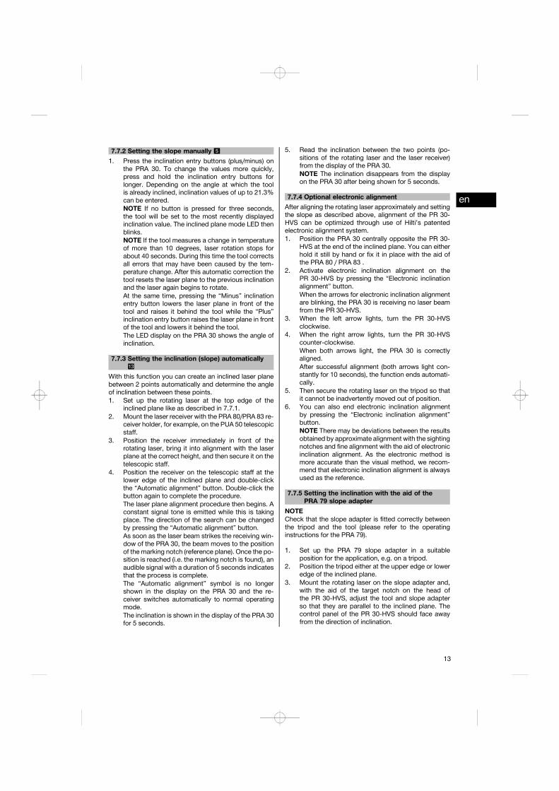
7.7.2 Setting the slope manually 5
1. Press the inclination entry buttons (plus/minus) onthe PRA 30. To change the values more quickly,press and hold the inclination entry buttons forlonger. Depending on the angle at which the toolis already inclined, inclination values of up to 21.3%can be entered.NOTE If no button is pressed for three seconds,the tool will be set to the most recently displayedinclination value. The inclined plane mode LED thenblinks.NOTE If the tool measures a change in temperatureof more than 10 degrees, laser rotation stops forabout 40 seconds. During this time the tool correctsall errors that may have been caused by the tem-perature change. After this automatic correction thetool resets the laser plane to the previous inclinationand the laser again begins to rotate.At the same time, pressing the “Minus” inclinationentry button lowers the laser plane in front of thetool and raises it behind the tool while the “Plus”inclination entry button raises the laser plane in frontof the tool and lowers it behind the tool.The LED display on the PRA 30 shows the angle ofinclination.
7.7.3 Setting the inclination (slope) automatically13
With this function you can create an inclined laser planebetween 2 points automatically and determine the angleof inclination between these points.1. Set up the rotating laser at the top edge of the
inclined plane like as described in 7.7.1.2. Mount the laser receiver with the PRA 80/PRA 83 re-
ceiver holder, for example, on the PUA 50 telescopicstaff.
3. Position the receiver immediately in front of therotating laser, bring it into alignment with the laserplane at the correct height, and then secure it on thetelescopic staff.
4. Position the receiver on the telescopic staff at thelower edge of the inclined plane and double-clickthe “Automatic alignment” button. Double-click thebutton again to complete the procedure.The laser plane alignment procedure then begins. Aconstant signal tone is emitted while this is takingplace. The direction of the search can be changedby pressing the “Automatic alignment” button.As soon as the laser beam strikes the receiving win-dow of the PRA 30, the beam moves to the positionof the marking notch (reference plane). Once the po-sition is reached (i.e. the marking notch is found), anaudible signal with a duration of 5 seconds indicatesthat the process is complete.The “Automatic alignment” symbol is no longershown in the display on the PRA 30 and the re-ceiver switches automatically to normal operatingmode.The inclination is shown in the display of the PRA 30for 5 seconds.
5. Read the inclination between the two points (po-sitions of the rotating laser and the laser receiver)from the display of the PRA 30.NOTE The inclination disappears from the displayon the PRA 30 after being shown for 5 seconds.
7.7.4 Optional electronic alignmentAfter aligning the rotating laser approximately and settingthe slope as described above, alignment of the PR 30-HVS can be optimized through use of Hilti’s patentedelectronic alignment system.1. Position the PRA 30 centrally opposite the PR 30-
HVS at the end of the inclined plane. You can eitherhold it still by hand or fix it in place with the aid ofthe PRA 80 / PRA 83 .
2. Activate electronic inclination alignment on thePR 30-HVS by pressing the “Electronic inclinationalignment” button.When the arrows for electronic inclination alignmentare blinking, the PRA 30 is receiving no laser beamfrom the PR 30-HVS.
3. When the left arrow lights, turn the PR 30-HVSclockwise.
4. When the right arrow lights, turn the PR 30-HVScounter-clockwise.When both arrows light, the PRA 30 is correctlyaligned.After successful alignment (both arrows light con-stantly for 10 seconds), the function ends automati-cally.
5. Then secure the rotating laser on the tripod so thatit cannot be inadvertently moved out of position.
6. You can also end electronic inclination alignmentby pressing the “Electronic inclination alignment”button.NOTE There may be deviations between the resultsobtained by approximate alignment with the sightingnotches and fine alignment with the aid of electronicinclination alignment. As the electronic method ismore accurate than the visual method, we recom-mend that electronic inclination alignment is alwaysused as the reference.
7.7.5 Setting the inclination with the aid of thePRA 79 slope adapter
NOTECheck that the slope adapter is fitted correctly betweenthe tripod and the tool (please refer to the operatinginstructions for the PRA 79).
1. Set up the PRA 79 slope adapter in a suitableposition for the application, e.g. on a tripod.
2. Position the tripod either at the upper edge or loweredge of the inclined plane.
3. Mount the rotating laser on the slope adapter and,with the aid of the target notch on the head ofthe PR 30-HVS, adjust the tool and slope adapterso that they are parallel to the inclined plane. Thecontrol panel of the PR 30-HVS should face awayfrom the direction of inclination.
en
13

4. Make sure that the slope adapter is in the zeroposition (0°).
5. Switch the tool on (see 7.2).6. Press the “Inclined plane mode” button.
The “Inclined plane mode” LED then lights on thecontrol panel of the rotating laser.The tool then begins automatic self-leveling. Thelaser switches on and begins to rotate as soon asthis is complete.
7. Set the slope adapter to the desired angle of incli-nation.NOTEWhen the angle of inclination is set manually,the PR 30-HVS levels the laser plane once and thensubsequently fixes it. Vibration, changes in temper-ature or other influences that may occur during thecourse of the day may affect the position of the laserplane.
7.8 Returning to standard modeTo return to standard operating mode, switch the tool offand then switch it back on again.
7.9 Sleep modeThe PR 30-HVS can save power when in sleep mode.The laser is switched off, thereby extending battery life.7.9.1 Activating sleep mode1. When the PRA 30 is switched off, press and hold the
on/off button of the PRA 30 for approx. 3 seconds.2. Press the “Right” arrow button twice to access
“Sleep mode” in the menu.3. Press the “Units” button to activate the sleep mode
on the PR 30-HVS.
7.9.2 Deactivating sleep mode1. When the PRA 30 is switched off, press and hold the
on/off button of the PRA 30 for approx. 3 seconds.2. Press the “Right” arrow button twice to access
“Sleep mode” in the menu.3. Press the “Units” button to deactivate the sleep
mode on the PR 30-HVS.4. To ensure working accuracy, check the laser set-
tings after the PR 30-HVS has been reactivated.
8 Care and maintenance8.1 Cleaning and drying1. Blow dust off exit windows.2. Do not touch the glass with the fingers.3. Use only a clean, soft cloth for cleaning. If necessary,
moisten the cloth slightly with pure alcohol or a littlewater.NOTE Abrasive cleaning materials may scratch theglass and impair the accuracy of the laser tool.NOTE Do not use any other liquids as these maydamage the plastic components.
4. Dry the equipment, observing the maximum tem-peratures given in the technical data.NOTE Especially in summer and winter, take carethat the given maximum andminimum temperaturesare not exceeded, e.g. when the equipment is storedin a motor vehicle.
8.2 Care of the Li-ion batteryAvoid ingress of moisture.Charge the battery fully before using it for the first time.In order to achievemaximumbattery life, stopdischargingthe battery as soon as a significant drop in performanceis noticed.NOTEIf use of the tool continues, further battery discharge willbe stopped automatically before the battery cells sufferdamage. The tool switches itself off.
Charge the battery with the Hilti charger approved for usewith Li-ion batteries.NOTE- A conditioning charge (as is required with NiCd orNiMH batteries) is not necessary.
- Interruption of the charging procedure has no negativeeffect on battery life.
- Charging can be started at any time with no negativeeffect on battery life. There is no memory effect (aswith NiCd or NiMH batteries).
- For best results, batteries should be stored fullycharged in a cool dry place. Avoid charging the batteryin places subject to high ambient temperatures (e.g. ata window) as this has an adverse effect on battery lifeand increases the rate of self-discharge.
- If the battery no longer reaches full charge, it mayhave lost capacity due to aging or overstressing. Itis possible to continue working with a battery in thiscondition but it should be replaced in good time.
8.3 Storage1. Remove the appliance from its case if it has be-
come wet. Dry and clean the tool, its transportcontainer and accessories (while observing the per-missible temperature range). Repack the equipmentonly once it is completely dry.
2. Check the accuracy of the equipment before it isused after a long period of storage or transportation.
3. Remove rechargeable and non-rechargeable batter-ies from the tool or the laser receiver before storingthe units for long periods. The tool or laser re-ceiver may suffer damage caused by leakage fromrechargeable or non-rechargeable batteries.
8.4 TransportUse the Hilti toolbox or packaging of equivalent qualityfor transporting or shipping your equipment.CAUTIONAlways remove the batteries before shipping the tool.
en
14

8.5 Hilti Calibration ServiceWe recommend that the tool is checked by the Hilticalibration service at regular intervals in order to ver-ify its reliability in accordance with standards and legalrequirements.Use can be made of the Hilti calibration service at anytime, but checking at least once a year is recommended.The calibration service provides confirmation that thetool is in conformance, on the day it is tested, with thespecifications given in the operating instructions.The tool will be readjusted if deviations from the man-ufacturer’s specification are found. After checking andadjustment, a calibration sticker applied to the tool anda calibration certificate provide written verification thatthe tool operates in accordance with the manufacturer’sspecification.Calibration certificates are always required by companiescertified according to ISO 900x.Your local Hilti Center or representative will be pleasedto provide further information.
8.6 Checking accuracyNOTEIn order to ensure compliance with the technical speci-fications, the tool should be checked regularly (at leastbefore each major / relevant job).
NOTEAfter falling and suffering an impact it can be presumedthat the tool will continue to operate faultlessly, withthe accuracy it achieved prior to the impact, when thefollowing conditions are met:
The height of the fall did not exceed the height given inthe technical data.The tool suffered no obvious mechanical damage fromthe impact (e.g. breakage of the pentaprism).The tool projects a rotating laser beamwhen in operation.The tool operated faultlessly before the impact.
8.6.1 Checking the main and transverse horizontalaxes 10
1. Set up the tripod approx. 20 m from a wall and levelthe tripod head with a spirit level.
2. Mount the tool on the tripod and use the aimingnotch to aim the tool at the wall.
3. Use the receiver to catch the laser beam and marka point (point 1) on the wall.
4. Pivot the tool clockwise through 90° about its ownaxis. In doing so, ensure that the height of the tooldoes not change.
5. Use the laser receiver to catch the laser beam andmark a second point (point 2) on the wall.
6. Repeat steps 4 and 5 twice and mark points 3 and4 on the wall with the aid of the laser receiver.When this procedure is carried out carefully, thevertical distance between the two marked points 1and 3 (main axis) or, respectively, points 2 and 4(transverse axis) should be less than 3 mm (at 20 m).If the deviation is greater than this, the tool shouldbe returned to a Hilti Service Center for calibration.
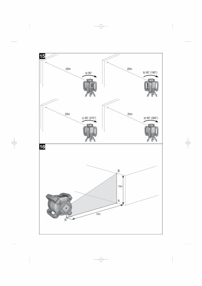
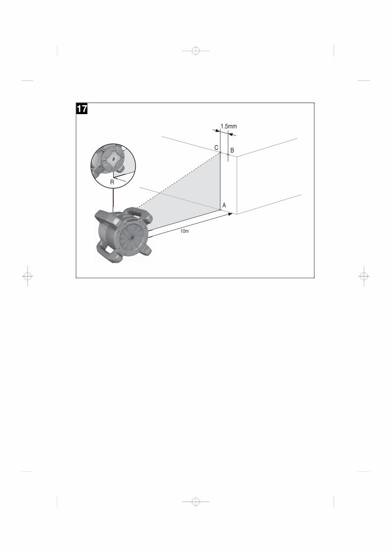
8.6.2 Checking the vertical axis 14 15
1. Place the tool in the vertical position on a flat floorapprox. 20 m from a wall.
2. Adjust the position of the tool so that the grips areparallel to the wall.
3. Switch the tool on and mark the reference point (R)on the floor.
4. With the aid of the receiver, mark point (A) low onthe wall. Select medium speed.
5. With the aid of the receiver, mark point (B) at aheight of approx. 10 m.
6. Pivot the tool through 180° and realign it with thereference point (R) on the floor and with point (A) atthe base of the wall.
7. With the aid of the receiver, mark point (C) at aheight of approx. 10 m.
8. Check the distance between points (B) and (C).When the procedure has been carried out carefully,the horizontal distance between the two points (B)and (C) marked at a height of 10 meters should beless than 1.5 mm (at 10 m).NOTE If the deviation is greater: Please return thetool to a Hilti Service Center for calibration.
9 TroubleshootingFault Possible cause RemedyThe display shows this symbol The PRA 30 has not been paired with
the PR 30-HVS.Pair the tools (see section 6.9)
en
15
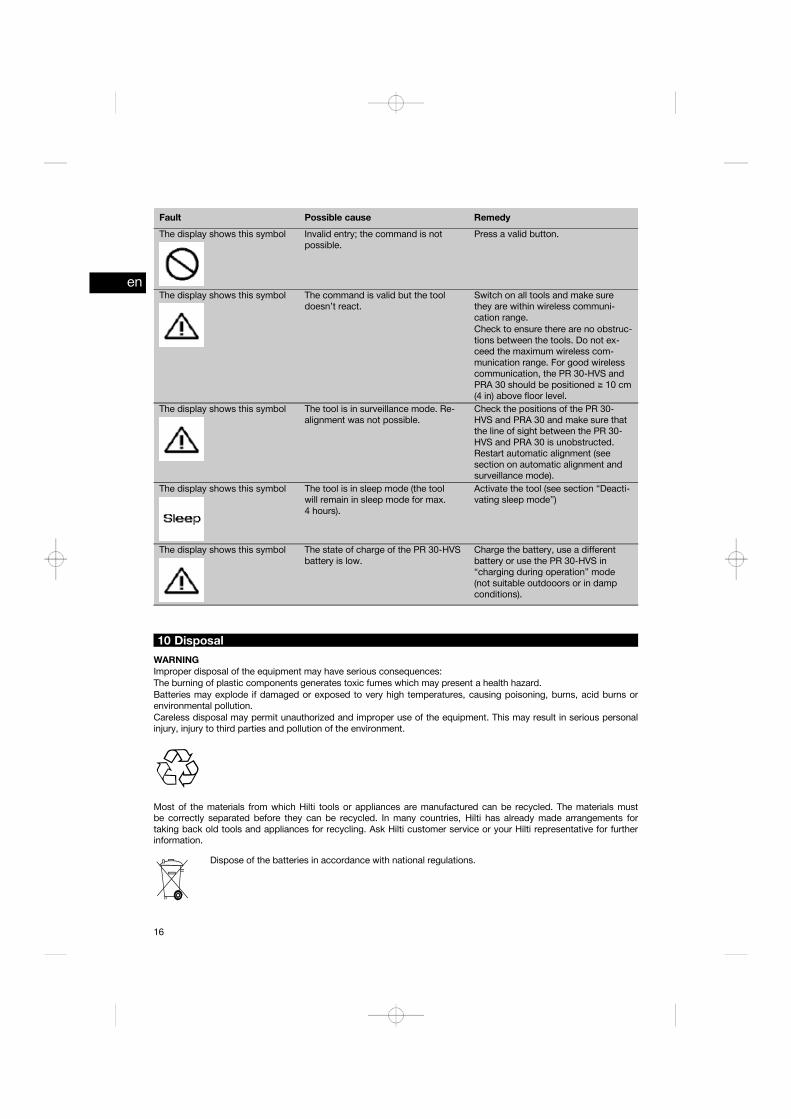
Fault Possible cause RemedyThe display shows this symbol Invalid entry; the command is not
possible.Press a valid button.
The display shows this symbol The command is valid but the tooldoesn’t react.
Switch on all tools and make surethey are within wireless communi-cation range.Check to ensure there are no obstruc-tions between the tools. Do not ex-ceed the maximum wireless com-munication range. For good wirelesscommunication, the PR 30-HVS andPRA 30 should be positioned ≧ 10 cm(4 in) above floor level.
The display shows this symbol The tool is in surveillance mode. Re-alignment was not possible.
Check the positions of the PR 30-HVS and PRA 30 and make sure thatthe line of sight between the PR 30-HVS and PRA 30 is unobstructed.Restart automatic alignment (seesection on automatic alignment andsurveillance mode).
The display shows this symbol The tool is in sleep mode (the toolwill remain in sleep mode for max.4 hours).
Activate the tool (see section “Deacti-vating sleep mode”)
The display shows this symbol The state of charge of the PR 30-HVSbattery is low.
Charge the battery, use a differentbattery or use the PR 30-HVS in“charging during operation” mode(not suitable outdooors or in dampconditions).
10 DisposalWARNINGImproper disposal of the equipment may have serious consequences:The burning of plastic components generates toxic fumes which may present a health hazard.Batteries may explode if damaged or exposed to very high temperatures, causing poisoning, burns, acid burns orenvironmental pollution.Careless disposal may permit unauthorized and improper use of the equipment. This may result in serious personalinjury, injury to third parties and pollution of the environment.
Most of the materials from which Hilti tools or appliances are manufactured can be recycled. The materials mustbe correctly separated before they can be recycled. In many countries, Hilti has already made arrangements fortaking back old tools and appliances for recycling. Ask Hilti customer service or your Hilti representative for furtherinformation.
Dispose of the batteries in accordance with national regulations.
en
16
11 Manufacturer’s warranty - toolsHilti warrants that the tool supplied is free of defects inmaterial and workmanship. This warranty is valid so longas the tool is operated and handled correctly, cleanedand serviced properly and in accordance with the HiltiOperating Instructions, and the technical system is main-tained. This means that only original Hilti consumables,components and spare parts may be used in the tool.
This warranty provides the free-of-charge repair or re-placement of defective parts only over the entire lifespanof the tool. Parts requiring repair or replacement as aresult of normal wear and tear are not covered by thiswarranty.
Additional claims are excluded, unless stringent na-tional rules prohibit such exclusion. In particular, Hiltiis not obligated for direct, indirect, incidental or con-sequential damages, losses or expenses in connec-tion with, or by reason of, the use of, or inability touse the tool for any purpose. Implied warranties ofmerchantability or fitness for a particular purpose arespecifically excluded.
For repair or replacement, send the tool or related partsimmediately upon discovery of the defect to the addressof the local Hilti marketing organization provided.
This constitutes Hilti’s entire obligation with regard towarranty and supersedes all prior or contemporaneouscomments and oral or written agreements concerningwarranties.
12 FCC statement (applicable in US) / IC statement (applicable in Canada)CAUTIONThis equipment has been tested and found to complywith the limits for a class B digital device, pursuant topart 15 of the FCC rules. These limits are designed to pro-vide reasonable protection against harmful interferencein a residential installation. This equipment generates,uses and may radiate radio frequency energy. Accord-ingly, if not installed and used in accordance with theinstructions, it may cause harmful interference to radiocommunications.
However, there is no guarantee that interference will notoccur in a particular installation. If this equipment doescause harmful interference to radio or television recep-tion, which can be determined by turning the equipmentoff and on, the user is encouraged to try to correct theinterference by taking the following measures:
Reorient or relocate the receiving antenna.
Increase the separation between the equipment and re-ceiver.
Connect the equipment to a power outlet on a circuitdifferent from that to which the receiver is connected.
Consult your dealer or an experienced TV/radio techni-cian for assistance.
NOTEChanges or modifications not expressly approved by Hilticould limit the user’s right to operate the equipment.
This device complies with part 15 of the FCC Rules andRSS-210 of the IC.
Operation is subject to the following two conditions:
This device should cause no cause harmful interference.
This device must accept any interference received, in-cluding interference that may cause undesired operation.
en
17


Hilti CorporationLI-9494 SchaanTel.: +423 / 234 21 11Fax: +423 / 234 29 65www.hilti.com
Hilti = registered trademark of Hilti Corp., Schaan W 4271 | 0313 | 00-Pos. 3 | 1 Printed in Liechtenstein © 2013Right of technical and programme changes reserved S. E. & O. *0000000*
0000
000
0000000 / A2