Embed Size (px)
Citation preview
Operator ManualFor printer model:
MB200i
www.satoamerica.com
PN: 9001144C
Read this Operator Manual before and during usage of the above product.Keep this document handy for future reference.

PN: 9001144C
SATO America, Inc.10350A Nations Ford Road
Charlotte, NC 28273Main Phone: (704) 644.1650
Technical Support: (704) 644.1660Technical Support Fax: (704) 644.1661E-Mail: [email protected]
Copyright 2009 SATO America, Inc. All rights reserved
Table of Contents
Technical Data ....................................................................................1 - 1Basic Specifications.....................................................................................................1 - 2Optional Accessories .............................................................................................................. 1 - 9Power Items ............................................................................................................................ 1 - 9Portability enhancements...................................................................................................... 1 - 11Connectivity options.............................................................................................................. 1 - 13
Overview..............................................................................................2 - 1Overview......................................................................................................................2 - 2Product Features .................................................................................................................... 2 - 2Bluetooth/Wireless Communication ........................................................................................ 2 - 2Safety Precautions.................................................................................................................. 2 - 3
Setup....................................................................................................3 - 1Setup ...........................................................................................................................3 - 2Unpacking the printer.............................................................................................................. 3 - 2Part Names ............................................................................................................................. 3 - 3Functions of various parts....................................................................................................... 3 - 5Charging the battery pack with a charger ............................................................................... 3 - 6Charging the battery pack with the printer .............................................................................. 3 - 7Using the battery pack ............................................................................................................ 3 - 8Using the optional AC Adapter for power.............................................................................. 3 - 10Loading the label roll (Continuous mode) ............................................................................. 3 - 11Loading the label roll (Dispense mode) ................................................................................ 3 - 13
Operation and Configuration...............................................................4 - 1Operation and Configuration .......................................................................................4 - 2Turning the Printer On or Off .................................................................................................. 4 - 2Turning the printer On............................................................................................................. 4 - 2Turning the printer Off ............................................................................................................. 4 - 2Setting the DIP Switches ........................................................................................................ 4 - 3Performing a Test Print ........................................................................................................... 4 - 4Printing via the RS-232C Interface ......................................................................................... 4 - 6Basic Specifications for RS-232C Interface ............................................................................ 4 - 6Input and Output Signals ........................................................................................................ 4 - 7Printing via the IrDA Interface ................................................................................................. 4 - 7Printing via the Optional Wireless LAN Interface .................................................................... 4 - 8Printing via the Optional Bluetooth Interface........................................................................... 4 - 8Optional LCD screen............................................................................................................. 4 - 10Adjusting Display Contrast .................................................................................................... 4 - 10Printer Configuration ............................................................................................................. 4 - 11Configuration Modes............................................................................................................. 4 - 13Normal Mode ........................................................................................................................ 4 - 13Label Sensor Selection ......................................................................................................... 4 - 14Dispense Mode ..................................................................................................................... 4 - 15Download Mode .................................................................................................................... 4 - 16
MB200i Operator Manual
Font Download Mode............................................................................................................ 4 - 18Online Command Mode........................................................................................................ 4 - 20CRC (Cyclic Redundancy Check) Mode............................................................................... 4 - 21Sleep & Auto-Off Mode......................................................................................................... 4 - 22Printing Procedure ................................................................................................................ 4 - 23Adjusting printing for linerless labels .................................................................................... 4 - 24Choosing the Label Dispensing Mode .................................................................................. 4 - 25Configuring Dispense Mode ................................................................................................. 4 - 25Other Printer Modes ............................................................................................................. 4 - 26Normal Mode ........................................................................................................................ 4 - 27Test Print Mode .................................................................................................................... 4 - 27Head Check Setting Mode.................................................................................................... 4 - 29Online Command Compatibility Mode .................................................................................. 4 - 29Offset Configuration via Programming.................................................................................. 4 - 30
Operating Modes .................................................................................5 - 1Operating Modes.........................................................................................................5 - 2Enabling and Disabling Special Functions.............................................................................. 5 - 2
Cleaning and Maintenance..................................................................6 - 1Cleaning and Maintenance..........................................................................................6 - 2Cleaning the Print Head.......................................................................................................... 6 - 2Cleaning the Platen and Dispenser Roller.............................................................................. 6 - 3
Troubleshooting ..................................................................................7 - 1Troubleshooting...........................................................................................................7 - 2What To Do In Case Of... ....................................................................................................... 7 - 2Error Indicators ....................................................................................................................... 7 - 3LCD Error Messages (WLAN Model Only) ............................................................................. 7 - 5
SATO Contacts ....................................................................................8 - 1SATO Group of Companies ........................................................................................8 - 2
MB200i Operator Manual

Unit 1: Technical Data
TECHNICAL DATA• Basic Specifications
MB200i Operator Manual Page 1-1
Unit 1: Technical Data
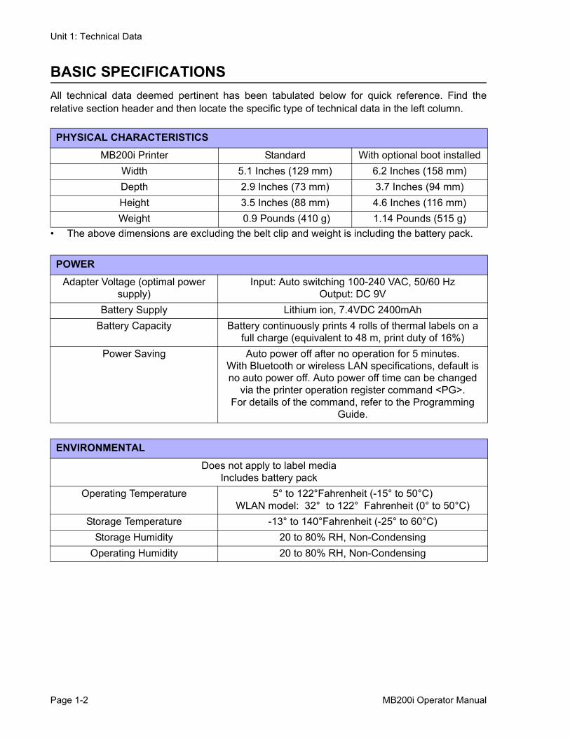
BASIC SPECIFICATIONSAll technical data deemed pertinent has been tabulated below for quick reference. Find therelative section header and then locate the specific type of technical data in the left column.
• The above dimensions are excluding the belt clip and weight is including the battery pack.
PHYSICAL CHARACTERISTICSMB200i Printer Standard With optional boot installed
Width 5.1 Inches (129 mm) 6.2 Inches (158 mm)Depth 2.9 Inches (73 mm) 3.7 Inches (94 mm)Height 3.5 Inches (88 mm) 4.6 Inches (116 mm)Weight 0.9 Pounds (410 g) 1.14 Pounds (515 g)
POWERAdapter Voltage (optimal power
supply)Input: Auto switching 100-240 VAC, 50/60 Hz
Output: DC 9VBattery Supply Lithium ion, 7.4VDC 2400mAh
Battery Capacity Battery continuously prints 4 rolls of thermal labels on a full charge (equivalent to 48 m, print duty of 16%)
Power Saving Auto power off after no operation for 5 minutes. With Bluetooth or wireless LAN specifications, default is no auto power off. Auto power off time can be changed
via the printer operation register command <PG>.For details of the command, refer to the Programming
Guide.
ENVIRONMENTALDoes not apply to label media
Includes battery packOperating Temperature 5° to 122°Fahrenheit (-15° to 50°C)
WLAN model: 32° to 122° Fahrenheit (0° to 50°C)Storage Temperature -13° to 140°Fahrenheit (-25° to 60°C)
Storage Humidity 20 to 80% RH, Non-CondensingOperating Humidity 20 to 80% RH, Non-Condensing
Page 1-2 MB200i Operator Manual
Unit 1: Technical Data
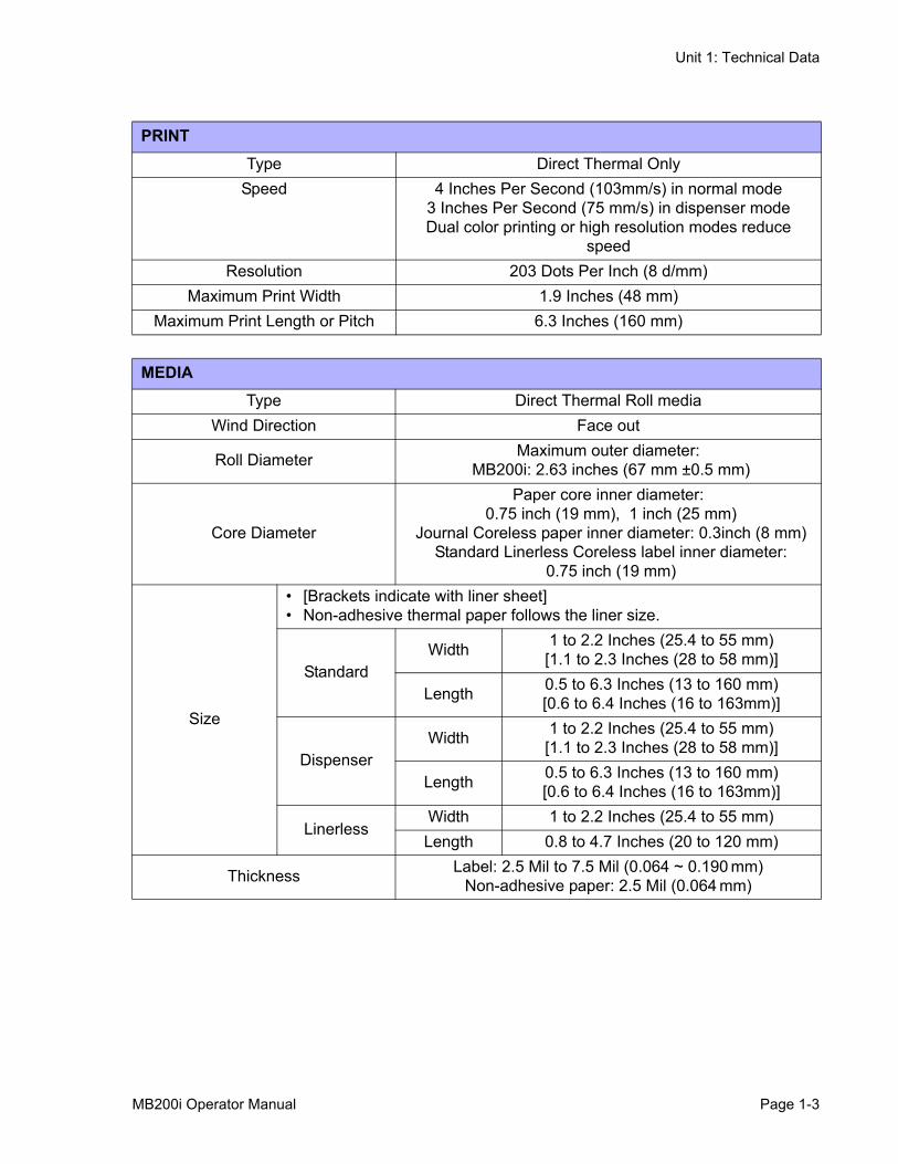
PRINTType Direct Thermal Only
Speed 4 Inches Per Second (103mm/s) in normal mode3 Inches Per Second (75 mm/s) in dispenser modeDual color printing or high resolution modes reduce
speedResolution 203 Dots Per Inch (8 d/mm)
Maximum Print Width 1.9 Inches (48 mm)Maximum Print Length or Pitch 6.3 Inches (160 mm)
MEDIAType Direct Thermal Roll media
Wind Direction Face out
Roll Diameter Maximum outer diameter:MB200i: 2.63 inches (67 mm ±0.5 mm)
Core Diameter
Paper core inner diameter:0.75 inch (19 mm), 1 inch (25 mm)
Journal Coreless paper inner diameter: 0.3inch (8 mm)Standard Linerless Coreless label inner diameter:
0.75 inch (19 mm)
Size
• [Brackets indicate with liner sheet]• Non-adhesive thermal paper follows the liner size.
StandardWidth 1 to 2.2 Inches (25.4 to 55 mm)
[1.1 to 2.3 Inches (28 to 58 mm)]
Length 0.5 to 6.3 Inches (13 to 160 mm)[0.6 to 6.4 Inches (16 to 163mm)]
DispenserWidth 1 to 2.2 Inches (25.4 to 55 mm)
[1.1 to 2.3 Inches (28 to 58 mm)]
Length 0.5 to 6.3 Inches (13 to 160 mm)[0.6 to 6.4 Inches (16 to 163mm)]
LinerlessWidth 1 to 2.2 Inches (25.4 to 55 mm)Length 0.8 to 4.7 Inches (20 to 120 mm)
Thickness Label: 2.5 Mil to 7.5 Mil (0.064 ~ 0.190 mm) Non-adhesive paper: 2.5 Mil (0.064 mm)
MB200i Operator Manual Page 1-3
Unit 1: Technical Data
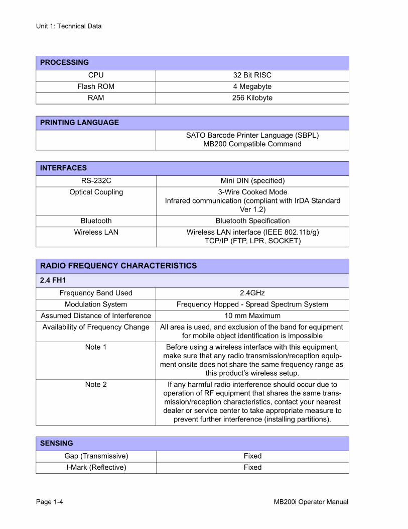
PROCESSINGCPU 32 Bit RISC
Flash ROM 4 MegabyteRAM 256 Kilobyte
PRINTING LANGUAGESATO Barcode Printer Language (SBPL)
MB200 Compatible Command
INTERFACESRS-232C Mini DIN (specified)
Optical Coupling 3-Wire Cooked ModeInfrared communication (compliant with IrDA Standard
Ver 1.2)Bluetooth Bluetooth Specification
Wireless LAN Wireless LAN interface (IEEE 802.11b/g)TCP/IP (FTP, LPR, SOCKET)
RADIO FREQUENCY CHARACTERISTICS
2.4 FH1Frequency Band Used 2.4GHz
Modulation System Frequency Hopped - Spread Spectrum SystemAssumed Distance of Interference 10 mm MaximumAvailability of Frequency Change All area is used, and exclusion of the band for equipment
for mobile object identification is impossibleNote 1 Before using a wireless interface with this equipment,
make sure that any radio transmission/reception equip-ment onsite does not share the same frequency range as
this product’s wireless setup. Note 2 If any harmful radio interference should occur due to
operation of RF equipment that shares the same trans-mission/reception characteristics, contact your nearest dealer or service center to take appropriate measure to
prevent further interference (installing partitions).
SENSINGGap (Transmissive) FixedI-Mark (Reflective) Fixed
Page 1-4 MB200i Operator Manual
Unit 1: Technical Data
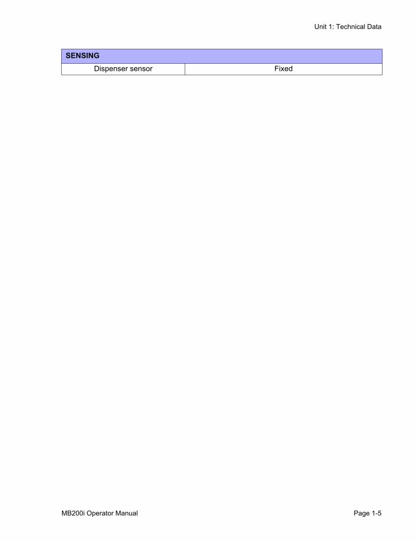
Dispenser sensor Fixed
SENSING
MB200i Operator Manual Page 1-5
Unit 1: Technical Data
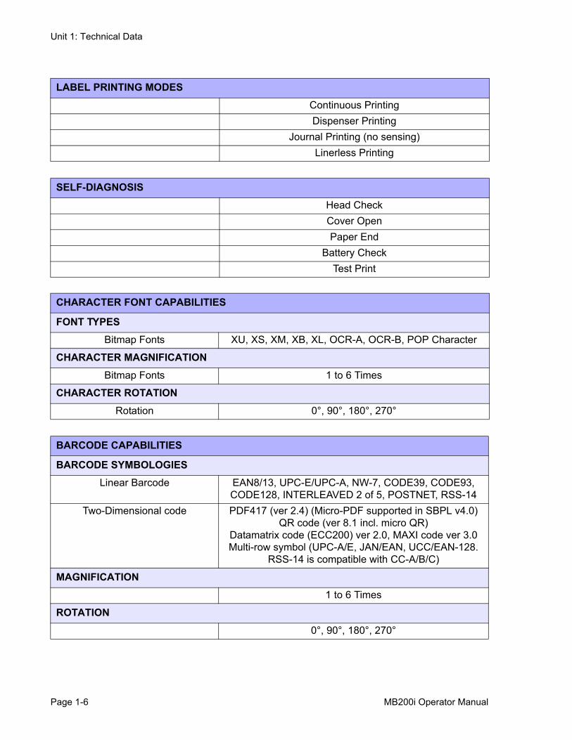
LABEL PRINTING MODESContinuous PrintingDispenser Printing
Journal Printing (no sensing)Linerless Printing
SELF-DIAGNOSISHead CheckCover OpenPaper End
Battery CheckTest Print
CHARACTER FONT CAPABILITIES
FONT TYPESBitmap Fonts XU, XS, XM, XB, XL, OCR-A, OCR-B, POP Character
CHARACTER MAGNIFICATIONBitmap Fonts 1 to 6 Times
CHARACTER ROTATIONRotation 0°, 90°, 180°, 270°
BARCODE CAPABILITIES
BARCODE SYMBOLOGIESLinear Barcode EAN8/13, UPC-E/UPC-A, NW-7, CODE39, CODE93,
CODE128, INTERLEAVED 2 of 5, POSTNET, RSS-14Two-Dimensional code PDF417 (ver 2.4) (Micro-PDF supported in SBPL v4.0)
QR code (ver 8.1 incl. micro QR)Datamatrix code (ECC200) ver 2.0, MAXI code ver 3.0Multi-row symbol (UPC-A/E, JAN/EAN, UCC/EAN-128.
RSS-14 is compatible with CC-A/B/C)
MAGNIFICATION1 to 6 Times
ROTATION0°, 90°, 180°, 270°
Page 1-6 MB200i Operator Manual
Unit 1: Technical Data
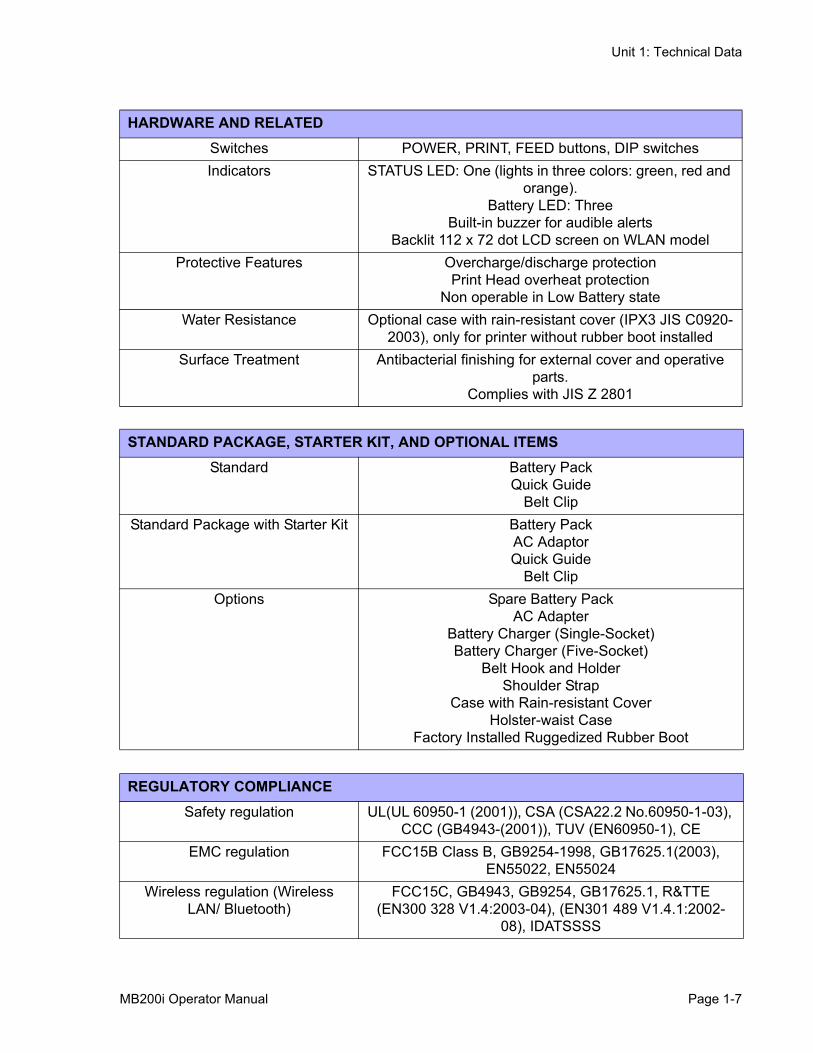
HARDWARE AND RELATEDSwitches POWER, PRINT, FEED buttons, DIP switchesIndicators STATUS LED: One (lights in three colors: green, red and
orange).Battery LED: Three
Built-in buzzer for audible alertsBacklit 112 x 72 dot LCD screen on WLAN model
Protective Features Overcharge/discharge protectionPrint Head overheat protection
Non operable in Low Battery stateWater Resistance Optional case with rain-resistant cover (IPX3 JIS C0920-
2003), only for printer without rubber boot installedSurface Treatment Antibacterial finishing for external cover and operative
parts.Complies with JIS Z 2801
STANDARD PACKAGE, STARTER KIT, AND OPTIONAL ITEMSStandard Battery Pack
Quick GuideBelt Clip
Standard Package with Starter Kit Battery PackAC AdaptorQuick Guide
Belt ClipOptions Spare Battery Pack
AC Adapter Battery Charger (Single-Socket) Battery Charger (Five-Socket)
Belt Hook and HolderShoulder Strap
Case with Rain-resistant CoverHolster-waist Case
Factory Installed Ruggedized Rubber Boot
REGULATORY COMPLIANCESafety regulation UL(UL 60950-1 (2001)), CSA (CSA22.2 No.60950-1-03),
CCC (GB4943-(2001)), TUV (EN60950-1), CEEMC regulation FCC15B Class B, GB9254-1998, GB17625.1(2003),
EN55022, EN55024Wireless regulation (Wireless
LAN/ Bluetooth)FCC15C, GB4943, GB9254, GB17625.1, R&TTE
(EN300 328 V1.4:2003-04), (EN301 489 V1.4.1:2002-08), IDATSSSS
MB200i Operator Manual Page 1-7
Unit 1: Technical Data
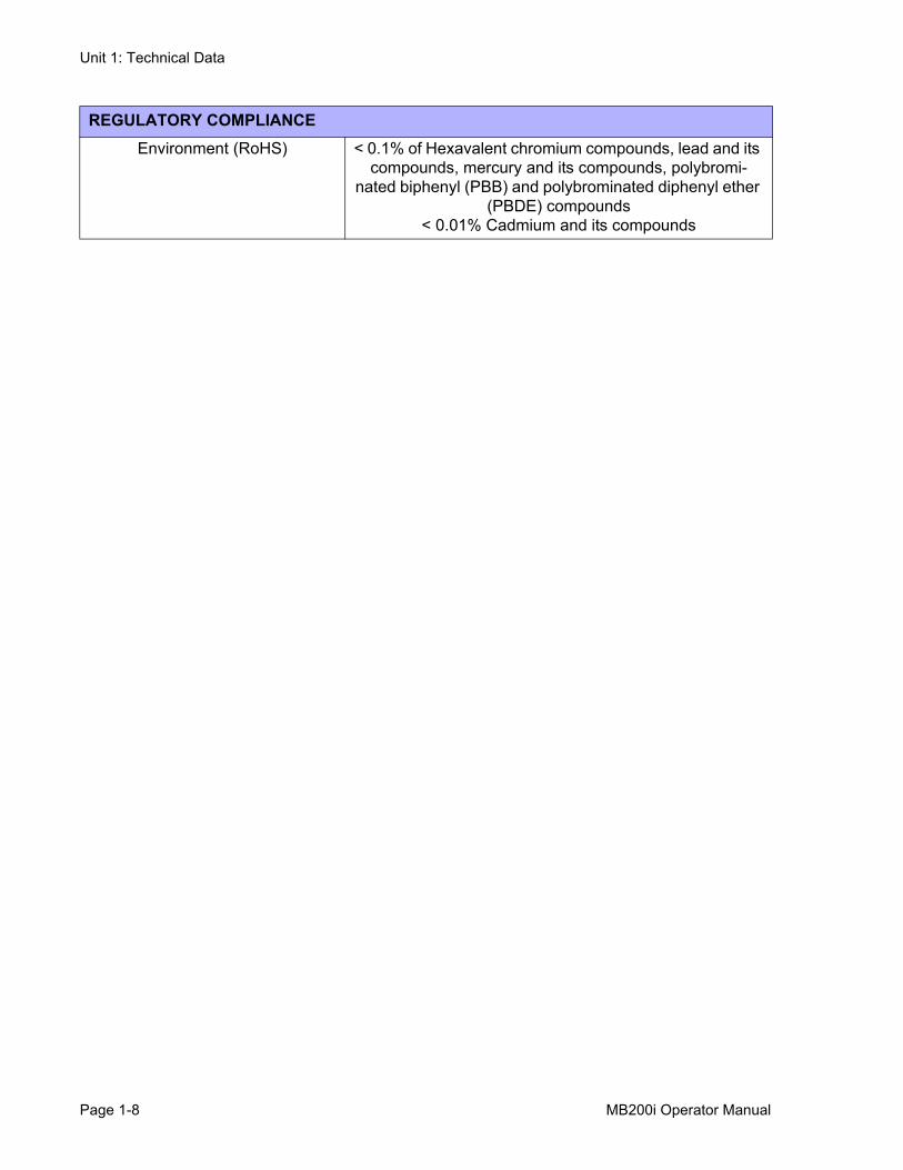
Environment (RoHS) < 0.1% of Hexavalent chromium compounds, lead and its compounds, mercury and its compounds, polybromi-
nated biphenyl (PBB) and polybrominated diphenyl ether (PBDE) compounds
< 0.01% Cadmium and its compounds
REGULATORY COMPLIANCE
Page 1-8 MB200i Operator Manual
Unit 1: Technical Data
OPTIONAL ACCESSORIESThe MB200i direct thermal printer is supported by a wide range of accessories to increase itsflexibility.
POWER ITEMS
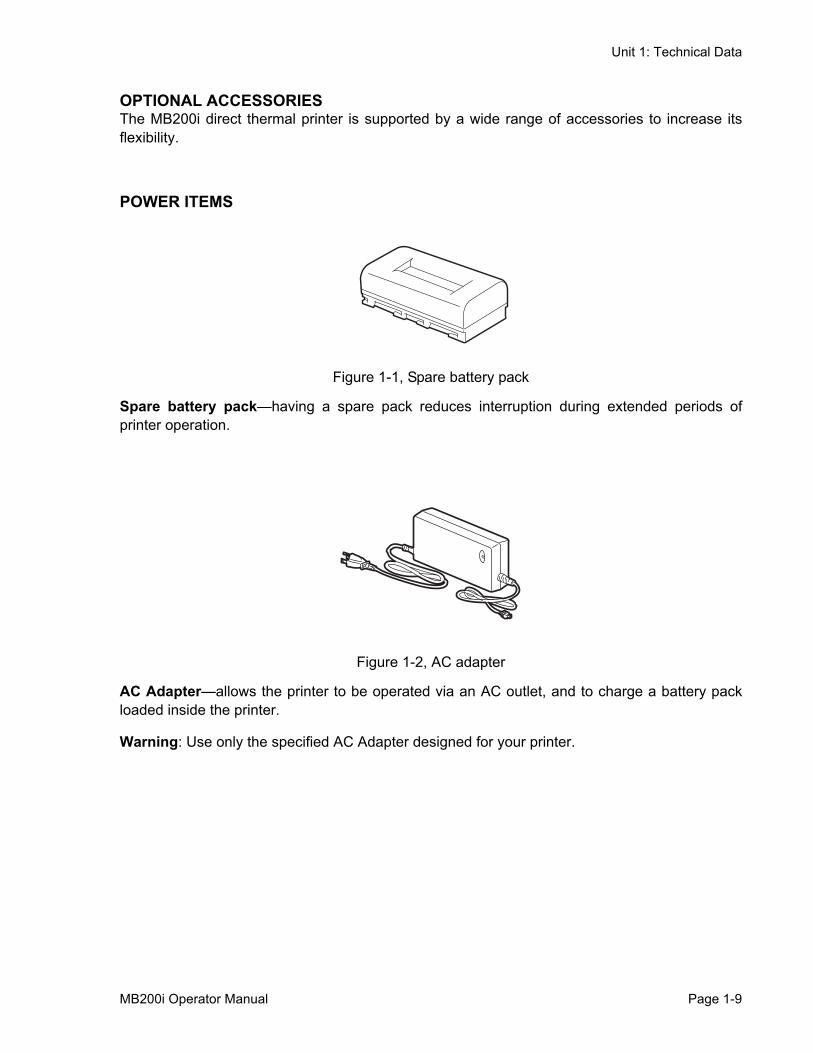
Figure 1-1, Spare battery pack
Spare battery pack—having a spare pack reduces interruption during extended periods ofprinter operation.
Figure 1-2, AC adapter
AC Adapter—allows the printer to be operated via an AC outlet, and to charge a battery packloaded inside the printer.
Warning: Use only the specified AC Adapter designed for your printer.
MB200i Operator Manual Page 1-9
Unit 1: Technical Data
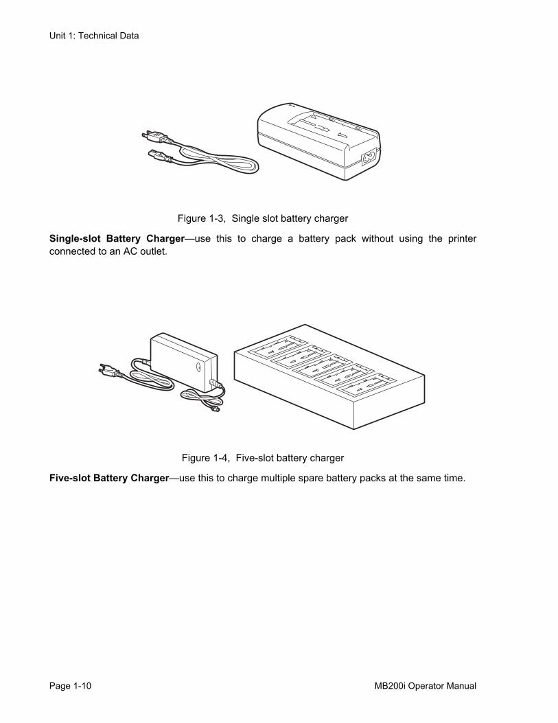
Figure 1-3, Single slot battery charger
Single-slot Battery Charger—use this to charge a battery pack without using the printerconnected to an AC outlet.
Figure 1-4, Five-slot battery charger
Five-slot Battery Charger—use this to charge multiple spare battery packs at the same time.
Page 1-10 MB200i Operator Manual
Unit 1: Technical Data
PORTABILITY ENHANCEMENTS
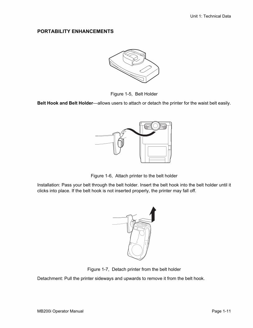
Figure 1-5, Belt Holder
Belt Hook and Belt Holder—allows users to attach or detach the printer for the waist belt easily.
Figure 1-6, Attach printer to the belt holder
Installation: Pass your belt through the belt holder. Insert the belt hook into the belt holder until itclicks into place. If the belt hook is not inserted properly, the printer may fall off.
Figure 1-7, Detach printer from the belt holder
Detachment: Pull the printer sideways and upwards to remove it from the belt hook.
MB200i Operator Manual Page 1-11
Unit 1: Technical Data
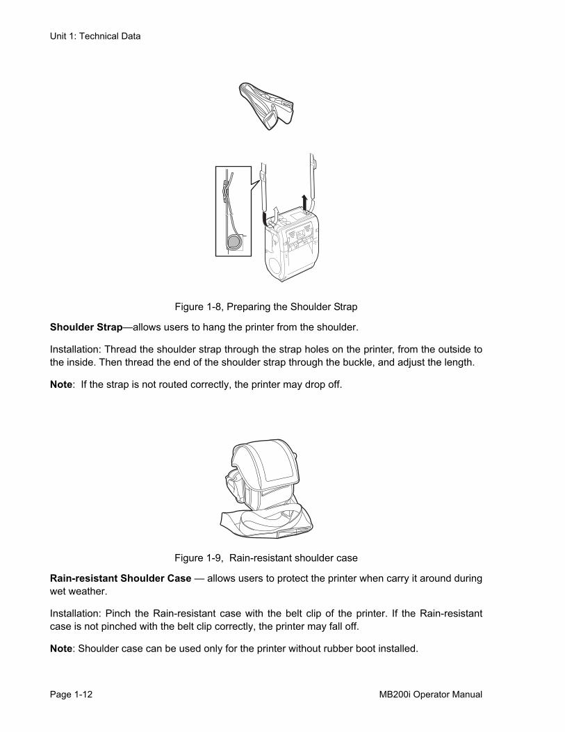
Figure 1-8, Preparing the Shoulder Strap
Shoulder Strap—allows users to hang the printer from the shoulder.
Installation: Thread the shoulder strap through the strap holes on the printer, from the outside tothe inside. Then thread the end of the shoulder strap through the buckle, and adjust the length.
Note: If the strap is not routed correctly, the printer may drop off.
Figure 1-9, Rain-resistant shoulder case
Rain-resistant Shoulder Case — allows users to protect the printer when carry it around duringwet weather.
Installation: Pinch the Rain-resistant case with the belt clip of the printer. If the Rain-resistantcase is not pinched with the belt clip correctly, the printer may fall off.
Note: Shoulder case can be used only for the printer without rubber boot installed.
Page 1-12 MB200i Operator Manual
Unit 1: Technical Data
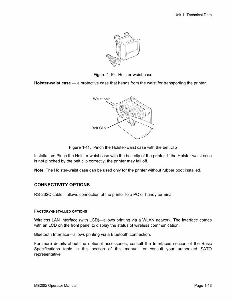
Figure 1-10, Holster-waist case
Holster-waist case — a protective case that hangs from the waist for transporting the printer.
Figure 1-11, Pinch the Holster-waist case with the belt clip
Installation: Pinch the Holster-waist case with the belt clip of the printer. If the Holster-waist caseis not pinched by the belt clip correctly, the printer may fall off.
Note: The Holster-waist case can be used only for the printer without rubber boot installed.
CONNECTIVITY OPTIONS
RS-232C cable—allows connection of the printer to a PC or handy terminal.
FACTORY-INSTALLED OPTIONS
Wireless LAN Interface (with LCD)—allows printing via a WLAN network. The interface comeswith an LCD on the front panel to display the status of wireless communication.
Bluetooth Interface—allows printing via a Bluetooth connection.
For more details about the optional accessories, consult the Interfaces section of the BasicSpecifications table in this section of this manual, or consult your authorized SATOrepresentative.
Waist belt
Belt Clip
MB200i Operator Manual Page 1-13

Unit 1: Technical Data
Page 1-14 MB200i Operator Manual
Unit 2: Overview
OVERVIEW• Overview
MB200i Operator Manual Page 2-1
Unit 2: Overview
OVERVIEWThis manual is laid out consistent with the product discussed and provides all of the informationrequired for operation of the MB200i printer.
A comprehensive Table Of Contents provided at the front of this manual facilitates rapidmovement within. The contents identify the different Units, Chapters, and Sections. Eachreferences the page number of their commencement.
The pages of this manual have embedded headers and footers to assist the user in identifyinghis or her exact position within the manual. The header provides the section number followed byits name. The footer identifies the product on the left, and the page number to the right side of thepage.
Page enumeration is two-part with each separated by a hyphen. The first character setreferences the Unit and the second identifies the page number. Page numbers begin with thenumeral (1) one at the commencement of a new unit and ascends sequentially.
This manual is intended to familiarize you with the basic features and operation of the MB200ibarcode printer in a short time.
PRODUCT FEATURESKey features:
• High speed CPU and 103 mm/sec print speed (max)• Long battery life• Durable and rugged design• Supports media up to 67 mm in width• Built-in label dispenser• Supports linerless media• Available in IrDA, RS232C (standard), Bluetooth (optional), and IEEE802.11 b/g (optional)
interfaces• Supports the MB200 compatible Programming Language or SATO Barcode Printer Language
Please read this manual carefully to make full use of this product. All information herein wascorrect at the time of this document’s release. Revised versions of this document may be createdto match updates in firmware and procedures.
BLUETOOTH/WIRELESS COMMUNICATIONCOMPLIANCE STATEMENTThis product has been certified for compliance with the relevant radio interference regulations ofyour country or region. To ensure continued compliance, do not:
• Disassemble or modify this product• Remove the certificate label (serial number seal) affixed to this product
Use of this product near microwave and/or other wireless LAN equipment, or where static
Page 2-2 MB200i Operator Manual
Unit 2: Overview
electricity or radio interference is present, may shorten the communication distance, or evendisable communication.
“Bluetooth” is a trademark of Bluetooth SIG, Inc., USA., and is used herein under license.
SAFETY PRECAUTIONSThis section outlines the safety precautions needed for safe operation of the printer. Make sureto read the precautions carefully before using the printer.
Symbols used in this manual:
The following symbols or markings are used in this manual and on the printer so that you canproperly use the printer, and to prevent any damage to property, harm or injury to yourself andothers.
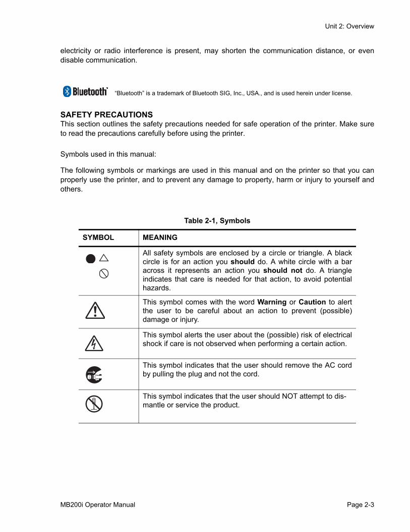
Table 2-1, Symbols
SYMBOL MEANING
All safety symbols are enclosed by a circle or triangle. A blackcircle is for an action you should do. A white circle with a baracross it represents an action you should not do. A triangleindicates that care is needed for that action, to avoid potentialhazards.
This symbol comes with the word Warning or Caution to alertthe user to be careful about an action to prevent (possible)damage or injury.
This symbol alerts the user about the (possible) risk of electricalshock if care is not observed when performing a certain action.
This symbol indicates that the user should remove the AC cordby pulling the plug and not the cord.
This symbol indicates that the user should NOT attempt to dis-mantle or service the product.
MB200i Operator Manual Page 2-3

Unit 2: Overview
USAGE SAFETY
• Do not place the printer in a hot or cold place
The operation temperature range is -15°C to 50°C (for wireless LAN: 0 to 50°C) where humidityis less than 80% and does not cause condensation. Do not place the printer in an area with highhumidity or at a temperature outside the specified range.
• Do not drop or apply undue shock to the printer
The printer is generally resistant to vibration possibly caused during normal transportation.However, do not apply extreme vibration or shock by dropping the printer.
• Do not disassemble or modify the printer
The printer has high-precision components inside requiring fine adjustment.
• Connect the correct cables to the input terminals
Cables of the correct specifications are required for connection to the external equipmentthrough the external input terminals. Contact your nearest dealer or service center if necessary.
• Use the recommended accessories
Using optional equipment other than the specified equipment may cause a malfunction. Alwaysuse the equipment specified in this guide.
• Use the correct media
Use the specified media. Otherwise, faulty printing or printer damage may occur.
USAGE WARNINGS
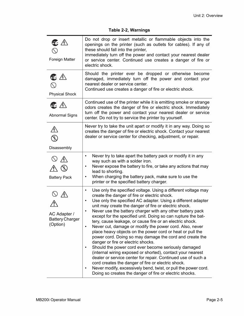
Table 2-2, Warnings
Liquids
Do not place any container with water or chemicals, such asflower vase or cup, as well as small metallic objects, near theprinter. If any of these should drop into the printer, immediatelyturn off the power and contact your nearest dealer or servicecenter. Continued use creates a danger of fire or electric shock.
Page 2-4 MB200i Operator Manual
Unit 2: Overview
Foreign Matter
Do not drop or insert metallic or flammable objects into theopenings on the printer (such as outlets for cables). If any ofthese should fall into the printer,immediately turn off the power and contact your nearest dealeror service center. Continued use creates a danger of fire orelectric shock.
Physical Shock
Should the printer ever be dropped or otherwise becomedamaged, immediately turn off the power and contact yournearest dealer or service center.Continued use creates a danger of fire or electric shock.
Abnormal Signs
Continued use of the printer while it is emitting smoke or strangeodors creates the danger of fire or electric shock. Immediatelyturn off the power and contact your nearest dealer or servicecenter. Do not try to service the printer by yourself.
Disassembly
Never try to take the unit apart or modify it in any way. Doing socreates the danger of fire or electric shock. Contact your nearestdealer or service center for checking, adjustment, or repair.
Battery Pack
• Never try to take apart the battery pack or modify it in any way such as with a solder iron.
• Never expose the battery to fire, or take any actions that may lead to shorting.
• When charging the battery pack, make sure to use the printer or the specified battery charger.
AC Adapter / Battery Charger (Option)
• Use only the specified voltage. Using a different voltage may create the danger of fire or electric shock.
• Use only the specified AC adapter. Using a different adapter unit may create the danger of fire or electric shock.
• Never use the battery charger with any other battery pack except for the specified unit. Doing so can rupture the bat-tery, cause leakage, or cause fire or an electric shock.
• Never cut, damage or modify the power cord. Also, never place heavy objects on the power cord or heat or pull the power cord. Doing so may damage the cord and create the danger or fire or electric shocks.
• Should the power cord ever become seriously damaged (internal wiring exposed or shorted), contact your nearest dealer or service center for repair. Continued use of such a cord creates the danger of fire or electric shock.
• Never modify, excessively bend, twist, or pull the power cord. Doing so creates the danger of fire or electric shocks.
Table 2-2, Warnings
MB200i Operator Manual Page 2-5
Unit 2: Overview
USAGE PRECAUTIONS
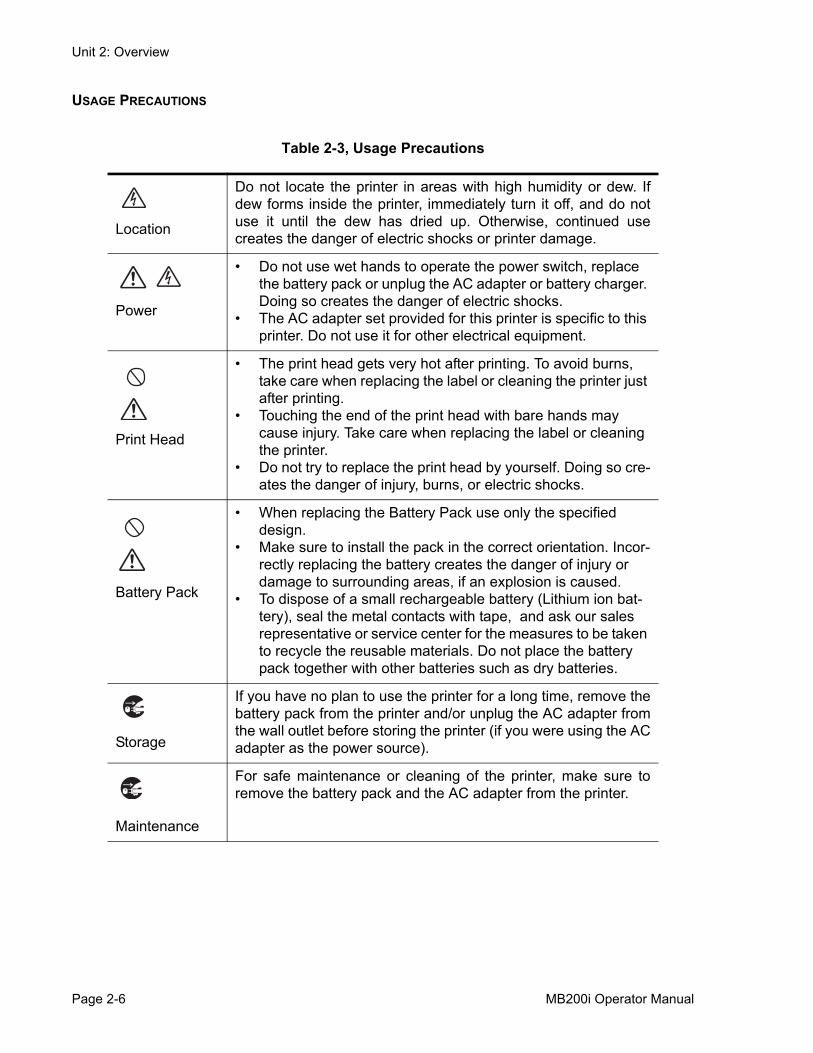
Table 2-3, Usage Precautions
Location
Do not locate the printer in areas with high humidity or dew. Ifdew forms inside the printer, immediately turn it off, and do notuse it until the dew has dried up. Otherwise, continued usecreates the danger of electric shocks or printer damage.
Power
• Do not use wet hands to operate the power switch, replace the battery pack or unplug the AC adapter or battery charger. Doing so creates the danger of electric shocks.
• The AC adapter set provided for this printer is specific to this printer. Do not use it for other electrical equipment.
Print Head
• The print head gets very hot after printing. To avoid burns, take care when replacing the label or cleaning the printer just after printing.
• Touching the end of the print head with bare hands may cause injury. Take care when replacing the label or cleaning the printer.
• Do not try to replace the print head by yourself. Doing so cre-ates the danger of injury, burns, or electric shocks.
Battery Pack
• When replacing the Battery Pack use only the specified design.
• Make sure to install the pack in the correct orientation. Incor-rectly replacing the battery creates the danger of injury or damage to surrounding areas, if an explosion is caused.
• To dispose of a small rechargeable battery (Lithium ion bat-tery), seal the metal contacts with tape, and ask our sales representative or service center for the measures to be taken to recycle the reusable materials. Do not place the battery pack together with other batteries such as dry batteries.
Storage
If you have no plan to use the printer for a long time, remove thebattery pack from the printer and/or unplug the AC adapter fromthe wall outlet before storing the printer (if you were using the ACadapter as the power source).
Maintenance
For safe maintenance or cleaning of the printer, make sure toremove the battery pack and the AC adapter from the printer.
Page 2-6 MB200i Operator Manual
Unit 3: Setup
SETUP• Setup
MB200i Operator Manual Page 3-1
Unit 3: Setup
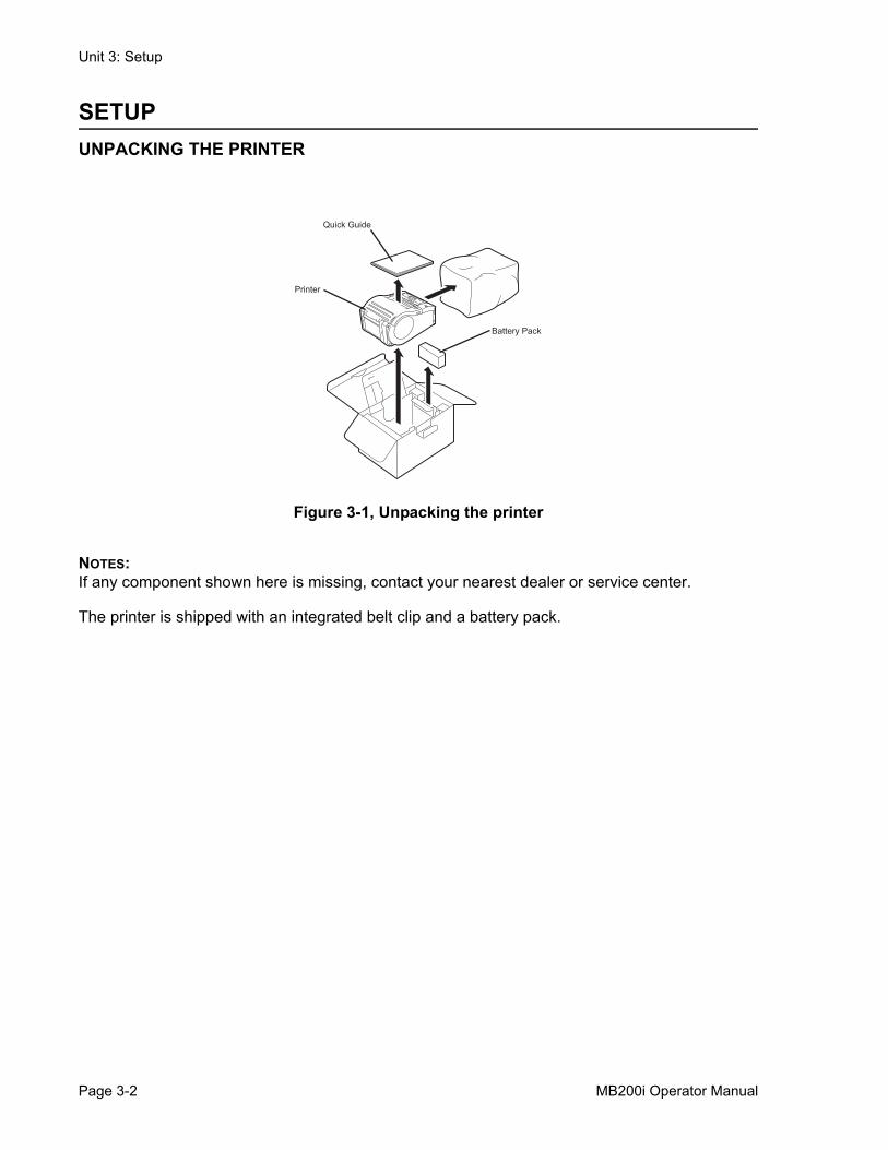
SETUPUNPACKING THE PRINTER
Figure 3-1, Unpacking the printer
NOTES:If any component shown here is missing, contact your nearest dealer or service center.
The printer is shipped with an integrated belt clip and a battery pack.
Quick Guide
Printer
Battery Pack
Page 3-2 MB200i Operator Manual
Unit 3: Setup
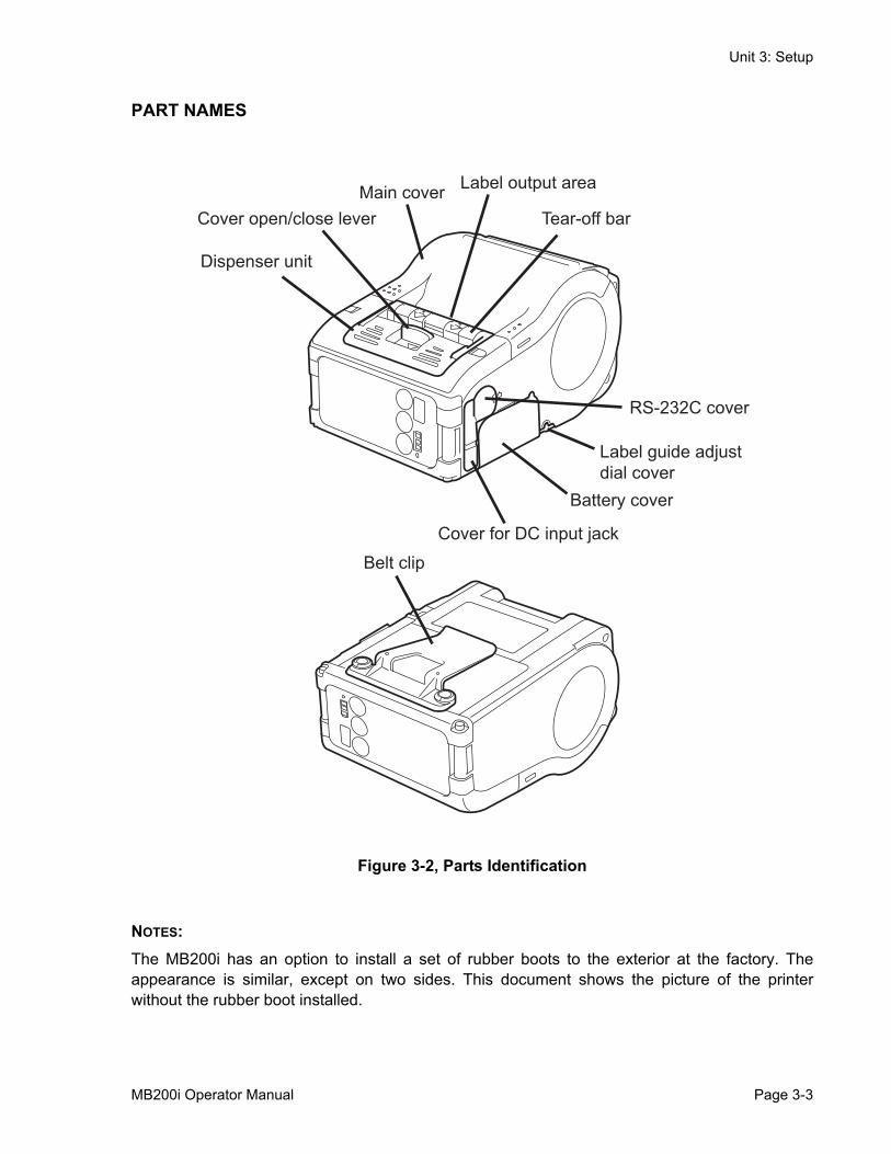
PART NAMES
Figure 3-2, Parts Identification
NOTES:The MB200i has an option to install a set of rubber boots to the exterior at the factory. Theappearance is similar, except on two sides. This document shows the picture of the printerwithout the rubber boot installed.
Cover open/close lever
Dispenser unit
Main cover Label output area
Tear-off bar
RS-232C cover
Label guide adjustdial cover
Battery cover
Cover for DC input jack
Belt clip
MB200i Operator Manual Page 3-3
Unit 3: Setup
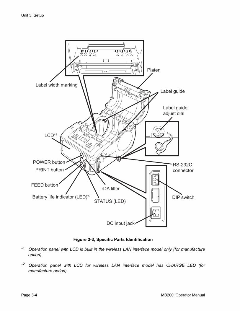
Figure 3-3, Specific Parts Identification
*1 Operation panel with LCD is built in the wireless LAN interface model only (for manufactureoption).
*2 Operation panel with LCD for wireless LAN interface model has CHARGE LED (formanufacture option).
23
4 4 D
1
03040558 03 04 05 85
Battery life indicator (LED)* 2
LCD* 1
Label width marking
Platen
Label guide
Label guide adjust dial
POWER button PRINT button
FEED button
STATUS (LED)
IrDA filter
DC input jack
DIP switch
RS-232C connector
Page 3-4 MB200i Operator Manual
Unit 3: Setup
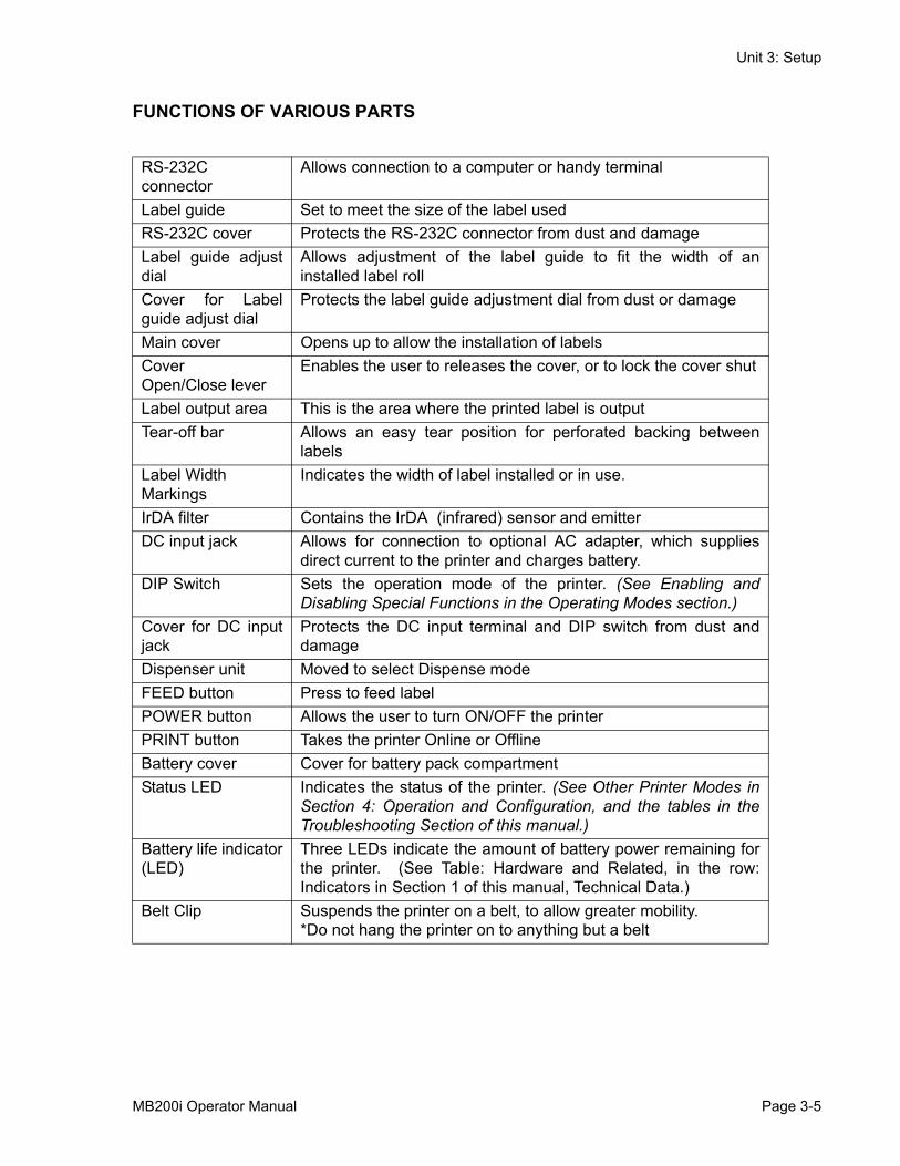
FUNCTIONS OF VARIOUS PARTS
RS-232C connector
Allows connection to a computer or handy terminal
Label guide Set to meet the size of the label usedRS-232C cover Protects the RS-232C connector from dust and damageLabel guide adjustdial
Allows adjustment of the label guide to fit the width of aninstalled label roll
Cover for Labelguide adjust dial
Protects the label guide adjustment dial from dust or damage
Main cover Opens up to allow the installation of labelsCover Open/Close lever
Enables the user to releases the cover, or to lock the cover shut
Label output area This is the area where the printed label is outputTear-off bar Allows an easy tear position for perforated backing between
labelsLabel WidthMarkings
Indicates the width of label installed or in use.
IrDA filter Contains the IrDA (infrared) sensor and emitterDC input jack Allows for connection to optional AC adapter, which supplies
direct current to the printer and charges battery.DIP Switch Sets the operation mode of the printer. (See Enabling and
Disabling Special Functions in the Operating Modes section.)Cover for DC inputjack
Protects the DC input terminal and DIP switch from dust anddamage
Dispenser unit Moved to select Dispense modeFEED button Press to feed labelPOWER button Allows the user to turn ON/OFF the printerPRINT button Takes the printer Online or OfflineBattery cover Cover for battery pack compartmentStatus LED Indicates the status of the printer. (See Other Printer Modes in
Section 4: Operation and Configuration, and the tables in theTroubleshooting Section of this manual.)
Battery life indicator(LED)
Three LEDs indicate the amount of battery power remaining forthe printer. (See Table: Hardware and Related, in the row:Indicators in Section 1 of this manual, Technical Data.)
Belt Clip Suspends the printer on a belt, to allow greater mobility.*Do not hang the printer on to anything but a belt
MB200i Operator Manual Page 3-5

Unit 3: Setup
CHARGING THE BATTERY PACK WITH A CHARGERIf you purchase the optional battery charger, you can use it to charge the supplied battery pack.Follow the steps below:
Figure 3-4, Charging the Battery Pack with a Charger
1. Connect the charger to the wall outlet and turn on the power. The POWER lamp lights red.
2. Align the battery pack with its metal contacts facing front, and slide it forward in the direction of the arrow to the charger.
The CHARGE lamp lights red when charging starts. It turns off when the battery pack is fully charged. In case of five-slot battery charger, when charging starts, the CHARGE lamp lights red. It then lights green when the battery packs are fully charged.
3. After charging, remove the battery pack from the charger by sliding it out.
NOTES:• If the POWER lamp does not light when you turn on the power, check the power cord connec-
tion.• If the CHARGE lamp does not light at the start of charging, make sure the battery pack is
firmly mounted into the charger. Poor mounting of the battery pack may result in faulty charg-ing.
• When the fully charged battery pack is placed into the battery charger, the CHARGE lamp turns on and then off. In the case of the five-slot charger, the CHARGE lamp lights green.
• When charging a battery pack that has not been used for a long time, the CHARGE lamp may blink for a while. This does not indicate an error. You can continue charging.
• The battery pack can be recharged about 300 times (when used at normal temperatures). If the battery pack is fully charged but runs out quickly, replace it with a new battery. The bat-tery may still be used, but the battery life may degrade over time.
CHARGING TIME It takes about 2.5 hours for a fully discharged battery pack to return to a fully charged state.
CRAH
GEOP WRE
metalcontacts
Page 3-6 MB200i Operator Manual
Unit 3: Setup
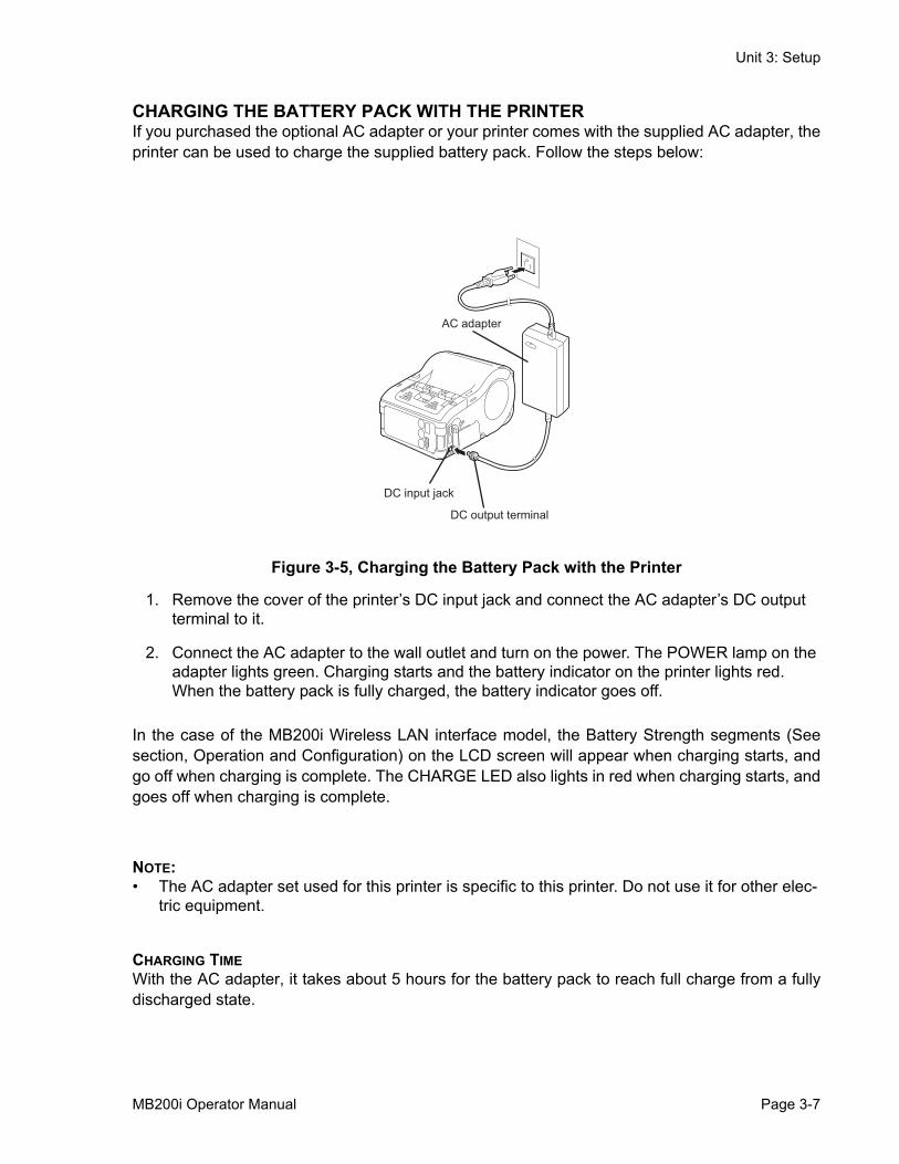
CHARGING THE BATTERY PACK WITH THE PRINTERIf you purchased the optional AC adapter or your printer comes with the supplied AC adapter, theprinter can be used to charge the supplied battery pack. Follow the steps below:
Figure 3-5, Charging the Battery Pack with the Printer
1. Remove the cover of the printer’s DC input jack and connect the AC adapter’s DC output terminal to it.
2. Connect the AC adapter to the wall outlet and turn on the power. The POWER lamp on the adapter lights green. Charging starts and the battery indicator on the printer lights red. When the battery pack is fully charged, the battery indicator goes off.
In the case of the MB200i Wireless LAN interface model, the Battery Strength segments (Seesection, Operation and Configuration) on the LCD screen will appear when charging starts, andgo off when charging is complete. The CHARGE LED also lights in red when charging starts, andgoes off when charging is complete.
NOTE:• The AC adapter set used for this printer is specific to this printer. Do not use it for other elec-
tric equipment.
CHARGING TIMEWith the AC adapter, it takes about 5 hours for the battery pack to reach full charge from a fullydischarged state.
AC adapter
DC input jack
DC output terminal
MB200i Operator Manual Page 3-7
Unit 3: Setup
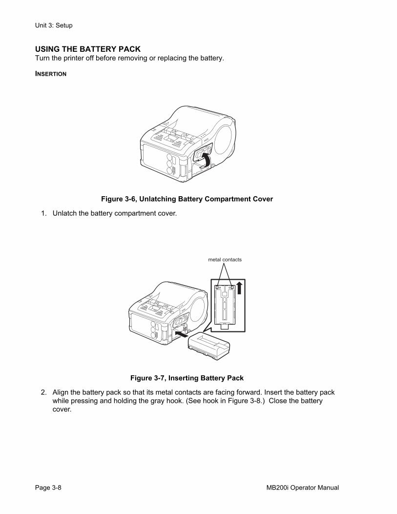
USING THE BATTERY PACKTurn the printer off before removing or replacing the battery.
INSERTION
Figure 3-6, Unlatching Battery Compartment Cover
1. Unlatch the battery compartment cover.
Figure 3-7, Inserting Battery Pack
2. Align the battery pack so that its metal contacts are facing forward. Insert the battery pack while pressing and holding the gray hook. (See hook in Figure 3-8.) Close the battery cover.
metal contacts
Page 3-8 MB200i Operator Manual
Unit 3: Setup
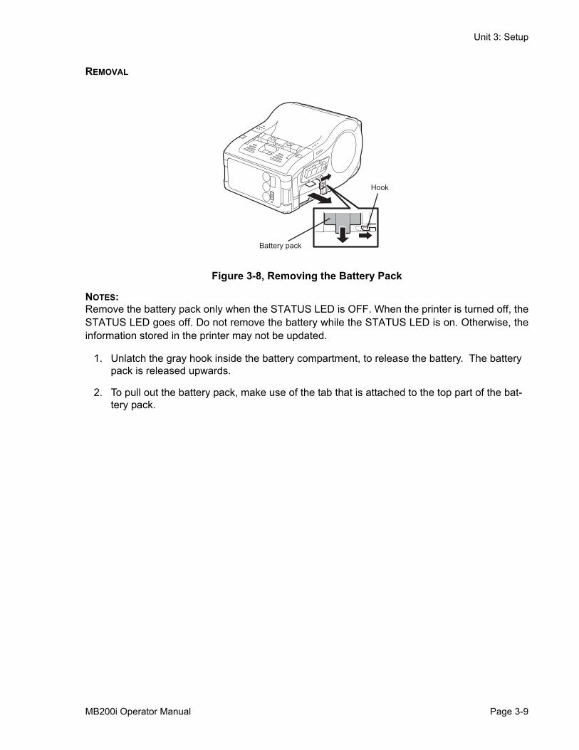
REMOVAL
Figure 3-8, Removing the Battery Pack
NOTES:Remove the battery pack only when the STATUS LED is OFF. When the printer is turned off, theSTATUS LED goes off. Do not remove the battery while the STATUS LED is on. Otherwise, theinformation stored in the printer may not be updated.
1. Unlatch the gray hook inside the battery compartment, to release the battery. The battery pack is released upwards.
2. To pull out the battery pack, make use of the tab that is attached to the top part of the bat-tery pack.
Hook
Battery pack
MB200i Operator Manual Page 3-9
Unit 3: Setup
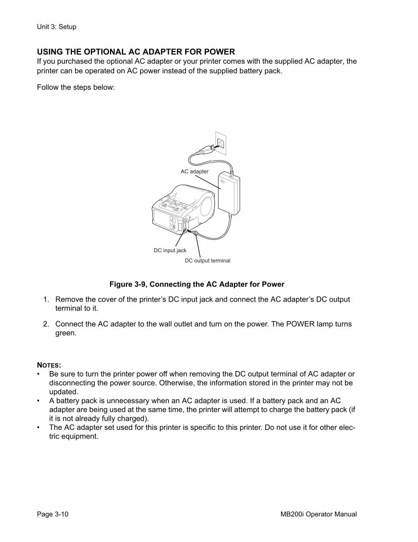
USING THE OPTIONAL AC ADAPTER FOR POWERIf you purchased the optional AC adapter or your printer comes with the supplied AC adapter, theprinter can be operated on AC power instead of the supplied battery pack.
Follow the steps below:
Figure 3-9, Connecting the AC Adapter for Power
1. Remove the cover of the printer’s DC input jack and connect the AC adapter’s DC output terminal to it.
2. Connect the AC adapter to the wall outlet and turn on the power. The POWER lamp turns green.
NOTES:• Be sure to turn the printer power off when removing the DC output terminal of AC adapter or
disconnecting the power source. Otherwise, the information stored in the printer may not be updated.
• A battery pack is unnecessary when an AC adapter is used. If a battery pack and an AC adapter are being used at the same time, the printer will attempt to charge the battery pack (if it is not already fully charged).
• The AC adapter set used for this printer is specific to this printer. Do not use it for other elec-tric equipment.
AC adapter
DC input jack
DC output terminal
Page 3-10 MB200i Operator Manual
Unit 3: Setup
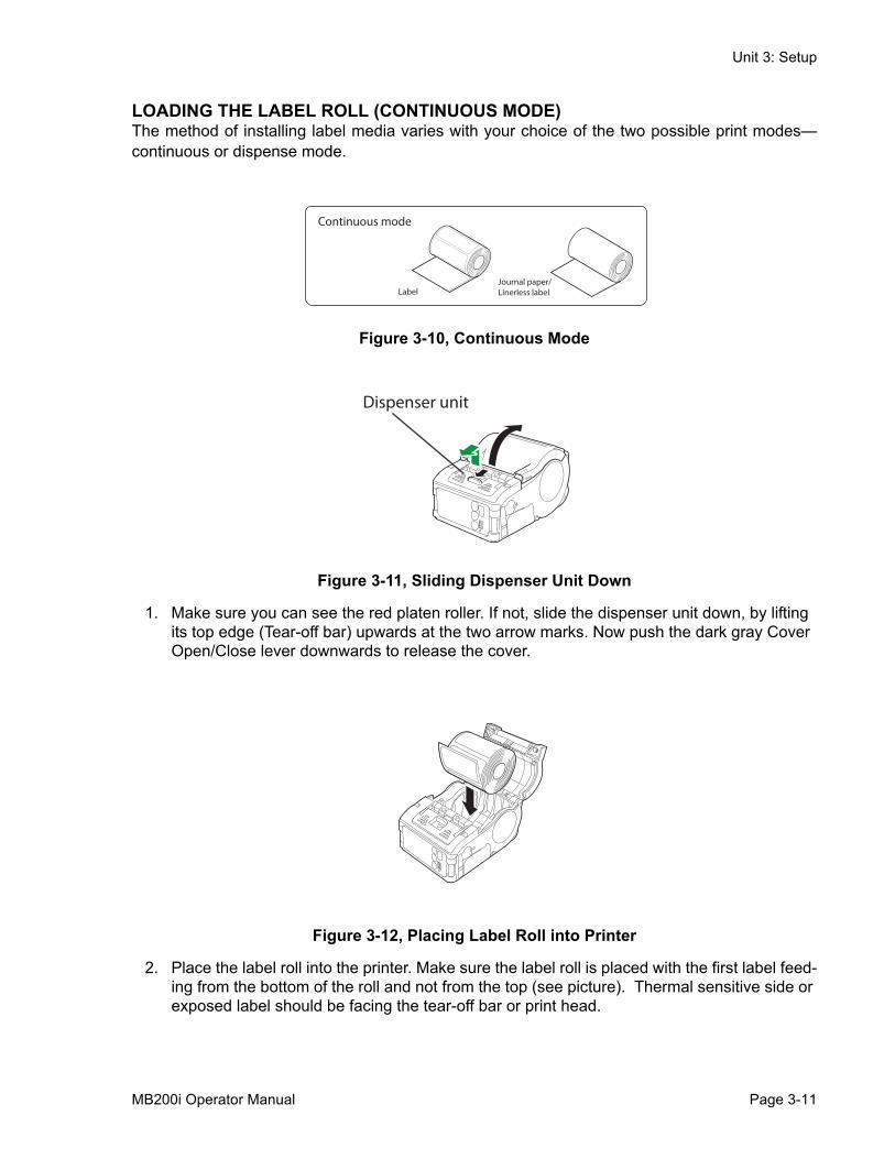
LOADING THE LABEL ROLL (CONTINUOUS MODE)The method of installing label media varies with your choice of the two possible print modes—continuous or dispense mode.
Figure 3-10, Continuous Mode
Figure 3-11, Sliding Dispenser Unit Down
1. Make sure you can see the red platen roller. If not, slide the dispenser unit down, by lifting its top edge (Tear-off bar) upwards at the two arrow marks. Now push the dark gray Cover Open/Close lever downwards to release the cover.
Figure 3-12, Placing Label Roll into Printer
2. Place the label roll into the printer. Make sure the label roll is placed with the first label feed-ing from the bottom of the roll and not from the top (see picture). Thermal sensitive side or exposed label should be facing the tear-off bar or print head.
Continuous mode
LabelJournal paper/ Linerless label
Dispenser unit
MB200i Operator Manual Page 3-11
Unit 3: Setup
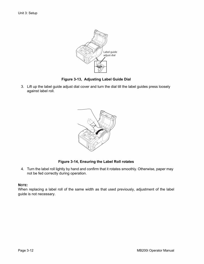
Figure 3-13, Adjusting Label Guide Dial
3. Lift up the label guide adjust dial cover and turn the dial till the label guides press loosely against label roll.
Figure 3-14, Ensuring the Label Roll rotates
4. Turn the label roll lightly by hand and confirm that it rotates smoothly. Otherwise, paper may not be fed correctly during operation.
NOTE:When replacing a label roll of the same width as that used previously, adjustment of the labelguide is not necessary.
Label guideadjust dial
Page 3-12 MB200i Operator Manual
Unit 3: Setup
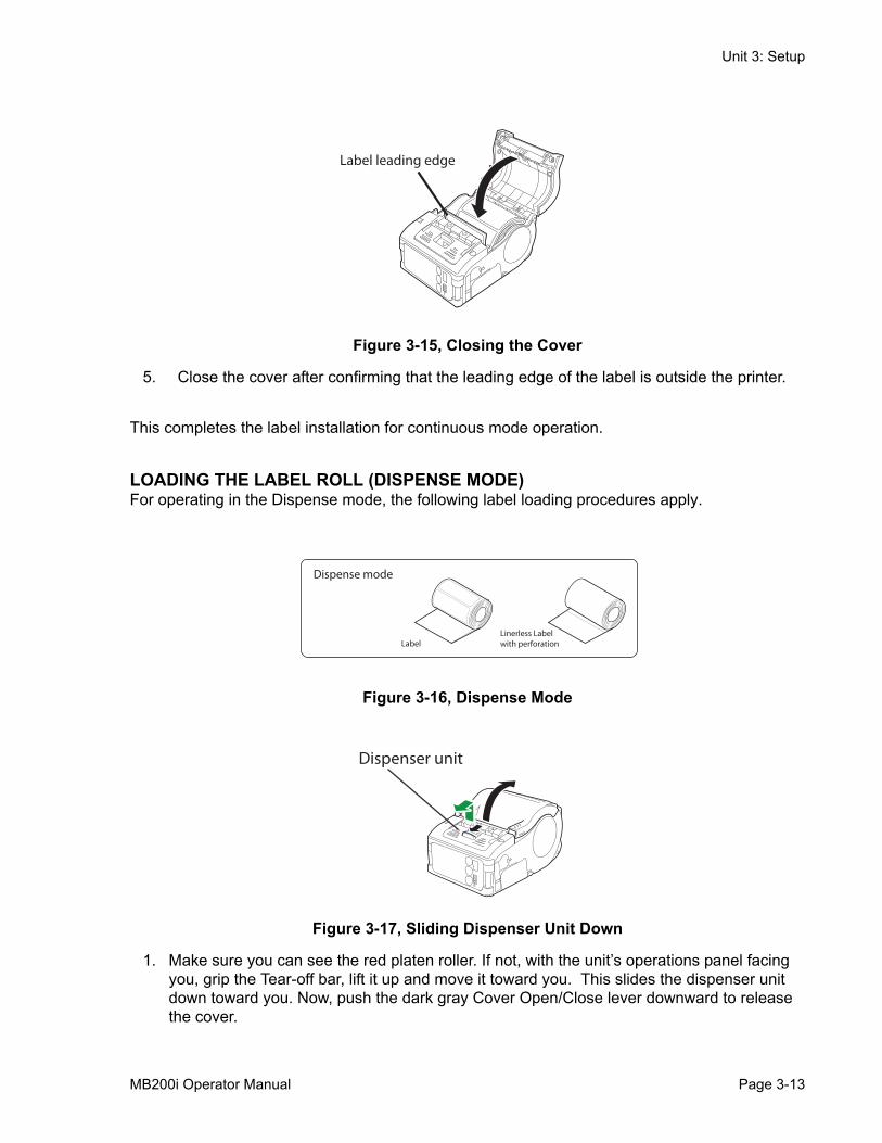
Figure 3-15, Closing the Cover
5. Close the cover after confirming that the leading edge of the label is outside the printer.
This completes the label installation for continuous mode operation.
LOADING THE LABEL ROLL (DISPENSE MODE)For operating in the Dispense mode, the following label loading procedures apply.
Figure 3-16, Dispense Mode
Figure 3-17, Sliding Dispenser Unit Down
1. Make sure you can see the red platen roller. If not, with the unit’s operations panel facing you, grip the Tear-off bar, lift it up and move it toward you. This slides the dispenser unit down toward you. Now, push the dark gray Cover Open/Close lever downward to release the cover.
Label leading edge
Dispense mode
LabelLinerless Labelwith perforation
Dispenser unit
MB200i Operator Manual Page 3-13
Unit 3: Setup
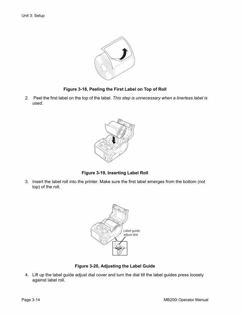
Figure 3-18, Peeling the First Label on Top of Roll
2. Peel the first label on the top of the label. This step is unnecessary when a linerless label is used.
Figure 3-19, Inserting Label Roll
3. Insert the label roll into the printer. Make sure the first label emerges from the bottom (not top) of the roll.
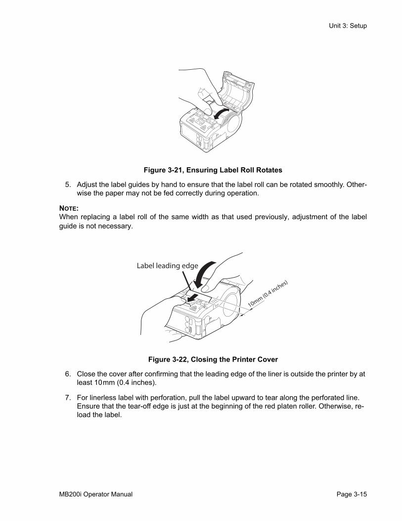
Figure 3-20, Adjusting the Label Guide
4. Lift up the label guide adjust dial cover and turn the dial till the label guides press loosely against label roll.
Label guideadjust dial
Page 3-14 MB200i Operator Manual
Unit 3: Setup
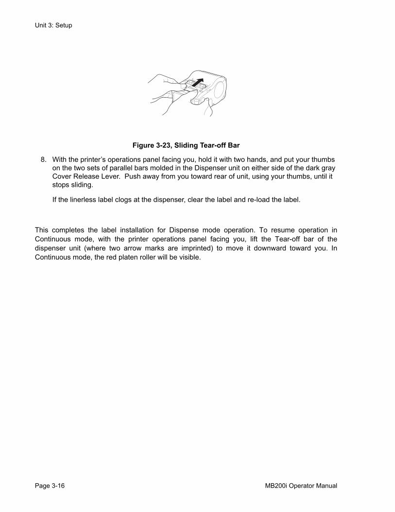
Figure 3-21, Ensuring Label Roll Rotates
5. Adjust the label guides by hand to ensure that the label roll can be rotated smoothly. Other-wise the paper may not be fed correctly during operation.
NOTE:When replacing a label roll of the same width as that used previously, adjustment of the labelguide is not necessary.
Figure 3-22, Closing the Printer Cover
6. Close the cover after confirming that the leading edge of the liner is outside the printer by at least 10mm (0.4 inches).
7. For linerless label with perforation, pull the label upward to tear along the perforated line. Ensure that the tear-off edge is just at the beginning of the red platen roller. Otherwise, re-load the label.
Label leading edge
10mm (0.4 inches)
MB200i Operator Manual Page 3-15
Unit 3: Setup
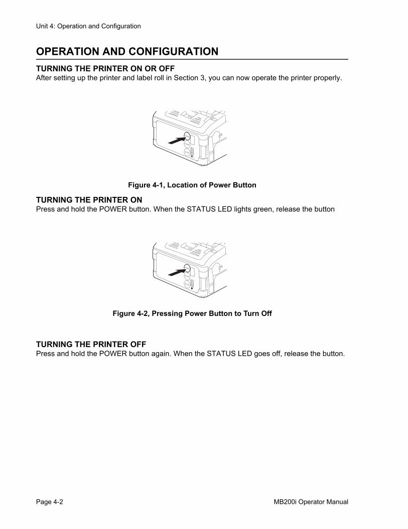
Figure 3-23, Sliding Tear-off Bar
8. With the printer’s operations panel facing you, hold it with two hands, and put your thumbs on the two sets of parallel bars molded in the Dispenser unit on either side of the dark gray Cover Release Lever. Push away from you toward rear of unit, using your thumbs, until it stops sliding.
If the linerless label clogs at the dispenser, clear the label and re-load the label.
This completes the label installation for Dispense mode operation. To resume operation inContinuous mode, with the printer operations panel facing you, lift the Tear-off bar of thedispenser unit (where two arrow marks are imprinted) to move it downward toward you. InContinuous mode, the red platen roller will be visible.
Page 3-16 MB200i Operator Manual

Unit 4: Operation and Configuration
OPERATION AND CONFIGURATION
• Operation and Configuration
MB200i Operator Manual Page 4-1
Unit 4: Operation and Configuration
OPERATION AND CONFIGURATIONTURNING THE PRINTER ON OR OFFAfter setting up the printer and label roll in Section 3, you can now operate the printer properly.
Figure 4-1, Location of Power Button
TURNING THE PRINTER ONPress and hold the POWER button. When the STATUS LED lights green, release the button
Figure 4-2, Pressing Power Button to Turn Off
TURNING THE PRINTER OFFPress and hold the POWER button again. When the STATUS LED goes off, release the button.
P OWE R
P R INT
FE E D
P OWE R
P R INT
FE E D
Page 4-2 MB200i Operator Manual
Unit 4: Operation and Configuration
SETTING THE DIP SWITCHES
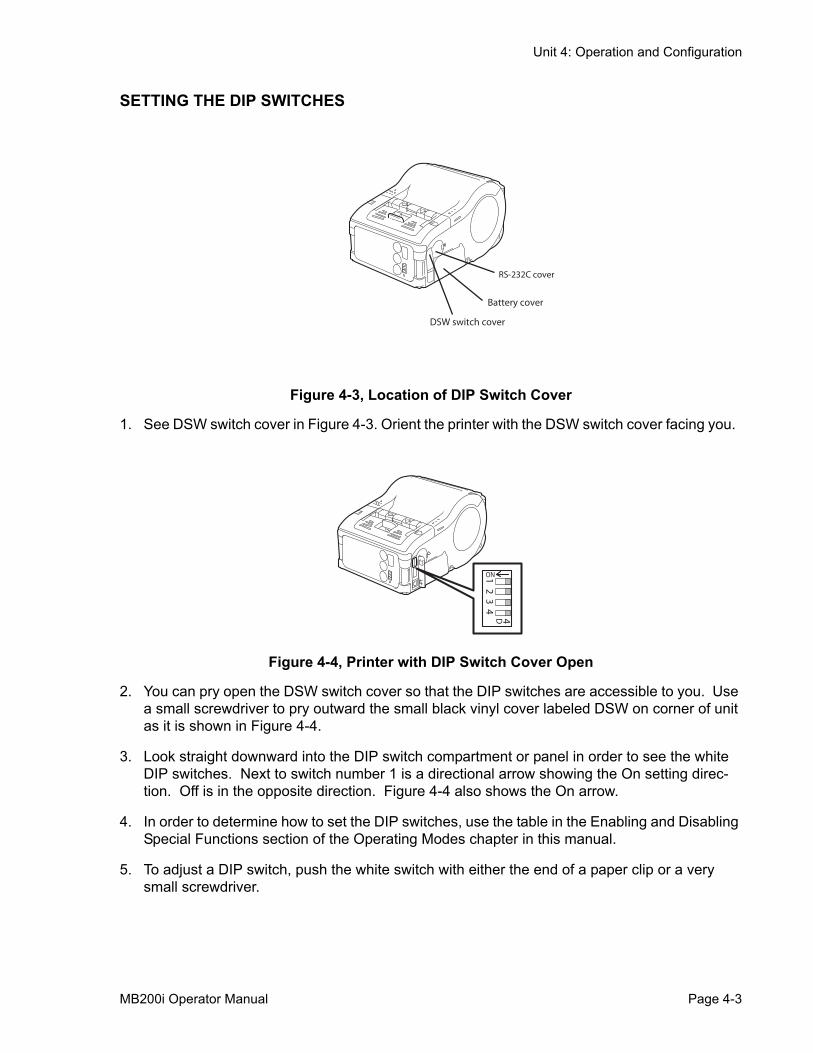
Figure 4-3, Location of DIP Switch Cover
1. See DSW switch cover in Figure 4-3. Orient the printer with the DSW switch cover facing you.
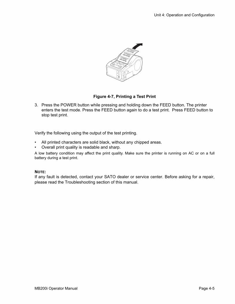
Figure 4-4, Printer with DIP Switch Cover Open
2. You can pry open the DSW switch cover so that the DIP switches are accessible to you. Use a small screwdriver to pry outward the small black vinyl cover labeled DSW on corner of unit as it is shown in Figure 4-4.
3. Look straight downward into the DIP switch compartment or panel in order to see the white DIP switches. Next to switch number 1 is a directional arrow showing the On setting direc-tion. Off is in the opposite direction. Figure 4-4 also shows the On arrow.
4. In order to determine how to set the DIP switches, use the table in the Enabling and Disabling Special Functions section of the Operating Modes chapter in this manual.
5. To adjust a DIP switch, push the white switch with either the end of a paper clip or a very small screwdriver.
RS-232C cover
Battery cover
DSW switch cover2
34
4D1ON
MB200i Operator Manual Page 4-3

Unit 4: Operation and Configuration
PERFORMING A TEST PRINTUsers can perform test prints to evaluate the print quality and also diagnose problems.
Figure 4-5, Printer with DIP Switch Cover Open
Figure 4-6, Pressing POWER and FEED buttons
1. Open the small black vinyl cover labeled DSW on side panel of unit. Figure 4-5 shows thecover for the DIP switches in the open position. The source of the enlarged view of theswitches are the parts under the small cover.
2. Set the printer DIP switch for User Test Print mode in the table in the Enabling and Disabling Special Functions section of the Operating Modes chapter in this manual.
23
4
4D1ON
POWER
FEED
1
2
Page 4-4 MB200i Operator Manual
Unit 4: Operation and Configuration
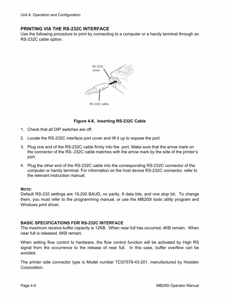
Figure 4-7, Printing a Test Print
3. Press the POWER button while pressing and holding down the FEED button. The printer enters the test mode. Press the FEED button again to do a test print. Press FEED button to stop test print.
Verify the following using the output of the test printing.
• All printed characters are solid black, without any chipped areas. • Overall print quality is readable and sharp.A low battery condition may affect the print quality. Make sure the printer is running on AC or on a fullbattery during a test print.
NOTE:If any fault is detected, contact your SATO dealer or service center. Before asking for a repair,please read the Troubleshooting section of this manual.
1234567abcdefg
1234567abcdefg
1234567abcdefg
MB200i Operator Manual Page 4-5
Unit 4: Operation and Configuration
PRINTING VIA THE RS-232C INTERFACEUse the following procedure to print by connecting to a computer or a handy terminal through anRS-232C cable option.
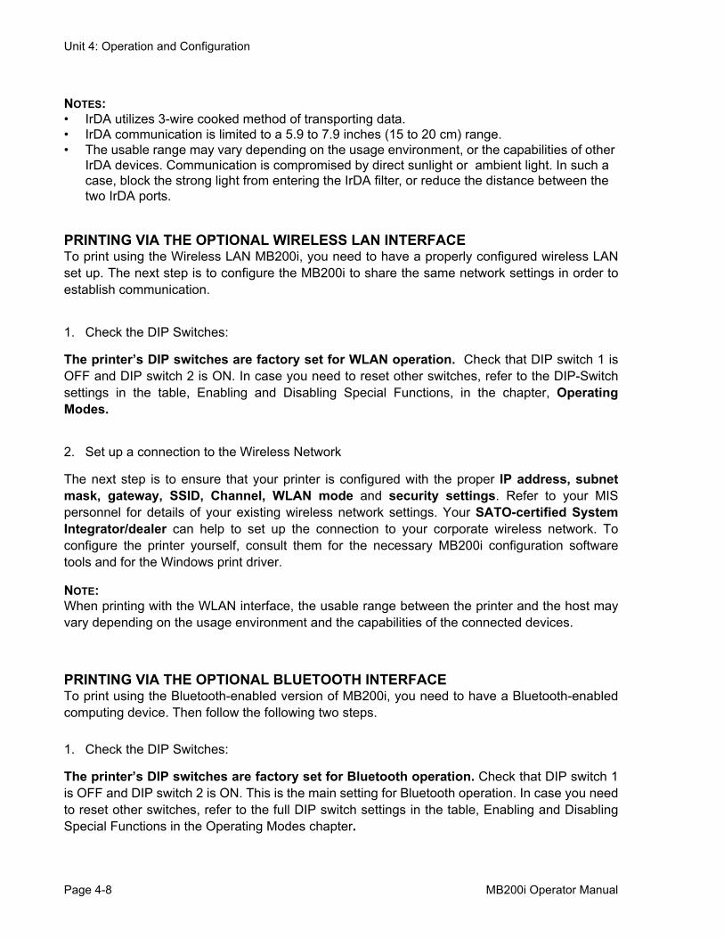
Figure 4-8, Inserting RS-232C Cable
1. Check that all DIP switches are off.
2. Locate the RS-232C interface port cover and lift it up to expose the port.
3. Plug one end of the RS-232C cable firmly into the port. Make sure that the arrow mark on the connector of the RS- 232C cable matches with the arrow mark by the side of the printer’s port.
4. Plug the other end of the RS-232C cable into the corresponding RS-232C connector of the computer or handy terminal. For information on the host device RS-232C connector, refer to the relevant instruction manual.
NOTE:Default RS-232 settings are 19,200 BAUD, no parity, 8 data bits, and one stop bit. To changethem, you must refer to the programming manual, or use the MB200i tools utility program andWindows print driver.
BASIC SPECIFICATIONS FOR RS-232C INTERFACEThe maximum receive buffer capacity is 12KB. When near full has occurred, 4KB remain. Whennear full is released, 6KB remain.
When setting flow control to hardware, the flow control function will be activated by High RSsignal from the occurrence to the release of near full. In this case, buffer overflow can beavoided.
The printer side connector type is Model number TCS7578-43-201, manufactured by HosidenCorporation.
RS-232Ccover
RS-232C cable
Page 4-6 MB200i Operator Manual

Unit 4: Operation and Configuration
INPUT AND OUTPUT SIGNALS
PRINTING VIA THE IRDA INTERFACEUse the following procedure to print through the IrDA interface.
1. Ensure that the DIP switch 1 is set to ON and DIP switch 2 to 4 are OFF.
Figure 4-9, Positioning the Printer
2. Place the printer 7.9 inches (20 cm) away from the IrDA port of the computer or handy termi-nal. Adjust the printer position so that the center of its IrDA filter projects a 30° conical area, which contains the IrDA transceiver of the computer or handy terminal.
PIN NUMBER SIGNAL I/O DESCRIPTION
1 SD Output Data to the host computer from the printer
5 CS Input Transmission request signal from the host (Flowcontrol)
3 - -
6 RD Input Data to the printer from the host computer
4 - -
2 RS Output Transmission request signal from the printer(Flow control)
7 SG - Signal ground
MB200i Operator Manual Page 4-7
Unit 4: Operation and Configuration
NOTES:• IrDA utilizes 3-wire cooked method of transporting data.• IrDA communication is limited to a 5.9 to 7.9 inches (15 to 20 cm) range.• The usable range may vary depending on the usage environment, or the capabilities of other
IrDA devices. Communication is compromised by direct sunlight or ambient light. In such a case, block the strong light from entering the IrDA filter, or reduce the distance between the two IrDA ports.
PRINTING VIA THE OPTIONAL WIRELESS LAN INTERFACETo print using the Wireless LAN MB200i, you need to have a properly configured wireless LANset up. The next step is to configure the MB200i to share the same network settings in order toestablish communication.
1. Check the DIP Switches:
The printer’s DIP switches are factory set for WLAN operation. Check that DIP switch 1 isOFF and DIP switch 2 is ON. In case you need to reset other switches, refer to the DIP-Switchsettings in the table, Enabling and Disabling Special Functions, in the chapter, OperatingModes.
2. Set up a connection to the Wireless Network
The next step is to ensure that your printer is configured with the proper IP address, subnetmask, gateway, SSID, Channel, WLAN mode and security settings. Refer to your MISpersonnel for details of your existing wireless network settings. Your SATO-certified SystemIntegrator/dealer can help to set up the connection to your corporate wireless network. Toconfigure the printer yourself, consult them for the necessary MB200i configuration softwaretools and for the Windows print driver.
NOTE:When printing with the WLAN interface, the usable range between the printer and the host mayvary depending on the usage environment and the capabilities of the connected devices.
PRINTING VIA THE OPTIONAL BLUETOOTH INTERFACETo print using the Bluetooth-enabled version of MB200i, you need to have a Bluetooth-enabledcomputing device. Then follow the following two steps.
1. Check the DIP Switches:
The printer’s DIP switches are factory set for Bluetooth operation. Check that DIP switch 1is OFF and DIP switch 2 is ON. This is the main setting for Bluetooth operation. In case you needto reset other switches, refer to the full DIP switch settings in the table, Enabling and DisablingSpecial Functions in the Operating Modes chapter.
Page 4-8 MB200i Operator Manual
Unit 4: Operation and Configuration
2. Synchronize Bluetooth settings
After setting the DIP-switches, the next step is to ensure that both Bluetooth devices areconfigured to operate with the same PIN code and Authentication mode settings. Refer to theinstruction manual of the computing device for details on how to set these parameters. Enter thedefault PIN code of 16 zeros.
For the MB200i, these parameters can be set by a SATO-certified System Integrator/dealer,or by using Bluetooth communication software available from your SATO dealer or servicecenter. To configure the printer yourself, you may use the MB200i configuration tool and theSATO Windows print driver.
NOTE:When printing with the Bluetooth interface, the usable range between the printer and the hostmay vary depending on the usage environment and the capabilities of the connected devices.
MB200i Operator Manual Page 4-9
Unit 4: Operation and Configuration
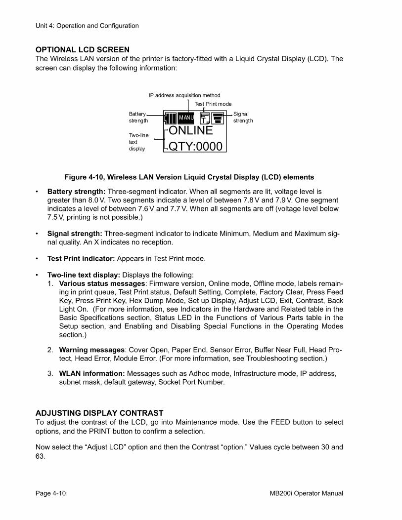
OPTIONAL LCD SCREENThe Wireless LAN version of the printer is factory-fitted with a Liquid Crystal Display (LCD). Thescreen can display the following information:
Figure 4-10, Wireless LAN Version Liquid Crystal Display (LCD) elements
• Battery strength: Three-segment indicator. When all segments are lit, voltage level is greater than 8.0 V. Two segments indicate a level of between 7.8 V and 7.9 V. One segment indicates a level of between 7.6 V and 7.7 V. When all segments are off (voltage level below 7.5 V, printing is not possible.)
• Signal strength: Three-segment indicator to indicate Minimum, Medium and Maximum sig-nal quality. An X indicates no reception.
• Test Print indicator: Appears in Test Print mode.
• Two-line text display: Displays the following:1. Various status messages: Firmware version, Online mode, Offline mode, labels remain-
ing in print queue, Test Print status, Default Setting, Complete, Factory Clear, Press FeedKey, Press Print Key, Hex Dump Mode, Set up Display, Adjust LCD, Exit, Contrast, BackLight On. (For more information, see Indicators in the Hardware and Related table in theBasic Specifications section, Status LED in the Functions of Various Parts table in theSetup section, and Enabling and Disabling Special Functions in the Operating Modessection.)
2. Warning messages: Cover Open, Paper End, Sensor Error, Buffer Near Full, Head Pro-tect, Head Error, Module Error. (For more information, see Troubleshooting section.)
3. WLAN information: Messages such as Adhoc mode, Infrastructure mode, IP address, subnet mask, default gateway, Socket Port Number.
ADJUSTING DISPLAY CONTRASTTo adjust the contrast of the LCD, go into Maintenance mode. Use the FEED button to selectoptions, and the PRINT button to confirm a selection.
Now select the “Adjust LCD” option and then the Contrast “option.” Values cycle between 30 and63.
ONLINEQTY:0000
MANU Signal strength
IP address acquisition method
Battery strength
Two-line text display
T
Test Print mode
Page 4-10 MB200i Operator Manual
Unit 4: Operation and Configuration
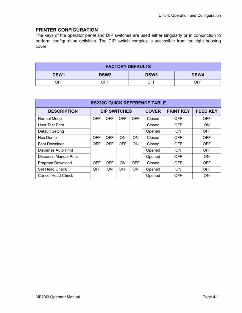
PRINTER CONFIGURATIONThe keys of the operator panel and DIP switches are used either singularly or in conjunction toperform configuration activities. The DIP switch complex is accessible from the right housingcover.
FACTORY DEFAULTS
DSW1 DSW2 DSW3 DSW4OFF OFF OFF OFF
RS232C QUICK REFERENCE TABLE
DESCRIPTION DIP SWITCHES COVER PRINT KEY FEED KEYNormal Mode OFF OFF OFF OFF Closed OFF OFFUser Test Print Closed OFF ONDefault Setting Opened ON OFFHex Dump OFF OFF ON ON Closed OFF OFFFont Download OFF OFF OFF ON Closed OFF OFFDispense Auto Print Opened ON OFFDispense Manual Print Opened OFF ONProgram Download OFF OFF ON OFF Closed OFF OFFSet Head Check OFF ON OFF ON Opened ON OFFCancel Head Check Opened OFF ON
MB200i Operator Manual Page 4-11
Unit 4: Operation and Configuration
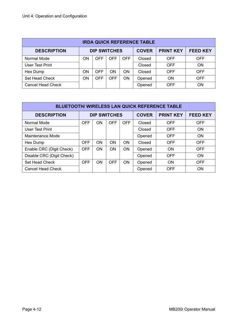
IRDA QUICK REFERENCE TABLE
DESCRIPTION DIP SWITCHES COVER PRINT KEY FEED KEYNormal Mode ON OFF OFF OFF Closed OFF OFFUser Test Print Closed OFF ONHex Dump ON OFF ON ON Closed OFF OFFSet Head Check ON OFF OFF ON Opened ON OFFCancel Head Check Opened OFF ON
BLUETOOTH/ WIRELESS LAN QUICK REFERENCE TABLE
DESCRIPTION DIP SWITCHES COVER PRINT KEY FEED KEYNormal Mode OFF ON OFF OFF Closed OFF OFFUser Test Print Closed OFF ONMaintenance Mode Opened OFF ONHex Dump OFF ON ON ON Closed OFF OFFEnable CRC (Digit Check) OFF ON ON ON Opened ON OFFDisable CRC (Digit Check) Opened OFF ONSet Head Check OFF ON OFF ON Opened ON OFFCancel Head Check Opened OFF ON
Page 4-12 MB200i Operator Manual
Unit 4: Operation and Configuration
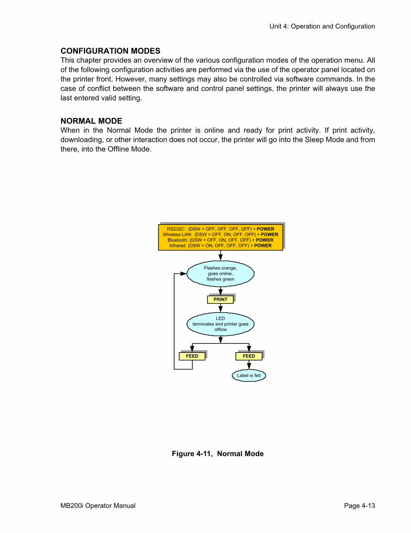
CONFIGURATION MODESThis chapter provides an overview of the various configuration modes of the operation menu. Allof the following configuration activities are performed via the use of the operator panel located onthe printer front. However, many settings may also be controlled via software commands. In thecase of conflict between the software and control panel settings, the printer will always use thelast entered valid setting.
NORMAL MODEWhen in the Normal Mode the printer is online and ready for print activity. If print activity,downloading, or other interaction does not occur, the printer will go into the Sleep Mode and fromthere, into the Offline Mode.
Figure 4-11, Normal Mode
RS232C: (DSW = OFF, OFF, OFF, OFF) + POWERWireless LAN: (DSW = OFF, ON, OFF, OFF) + POWER
Bluetooth: (DSW = OFF, ON, OFF, OFF) + POWERInfrared: (DSW = ON, OFF, OFF, OFF) + POWER
Flashes orange, goes online,
flashes green
FEEDFEED
LED terminates and printer goes
offline
Label is fed
MB200i Operator Manual Page 4-13
Unit 4: Operation and Configuration
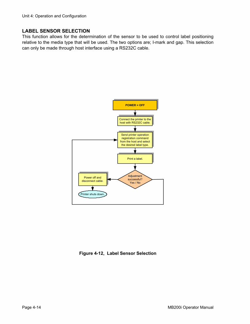
LABEL SENSOR SELECTIONThis function allows for the determination of the sensor to be used to control label positioningrelative to the media type that will be used. The two options are; I-mark and gap. This selectioncan only be made through host interface using a RS232C cable.
Figure 4-12, Label Sensor Selection
POWER = OFF
Connect the printer to the host with RS232C cable.
Printer shuts down.
Send printer operation registration command
from the host and select the desired label type.
Adjustment successful?
Yes / No
Power off and disconnect cable.
Print a label.
Page 4-14 MB200i Operator Manual
Unit 4: Operation and Configuration
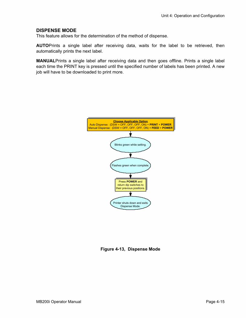
DISPENSE MODEThis feature allows for the determination of the method of dispense.
AUTOPrints a single label after receiving data, waits for the label to be retrieved, thenautomatically prints the next label.
MANUALPrints a single label after receiving data and then goes offline. Prints a single labeleach time the PRINT key is pressed until the specified number of labels has been printed. A newjob will have to be downloaded to print more.
Figure 4-13, Dispense Mode
Choose Applicable OptionAuto Dispense: (DSW = OFF, OFF, OFF, ON) + PRINT + POWER
Manual Dispense: (DSW = OFF, OFF, OFF, ON) + FEED + POWER
Blinks green while setting.
Press POWER and return dip switches to
their previous positions.
Flashes green when complete.
Printer shuts down and exits Dispense Mode.
MB200i Operator Manual Page 4-15
Unit 4: Operation and Configuration
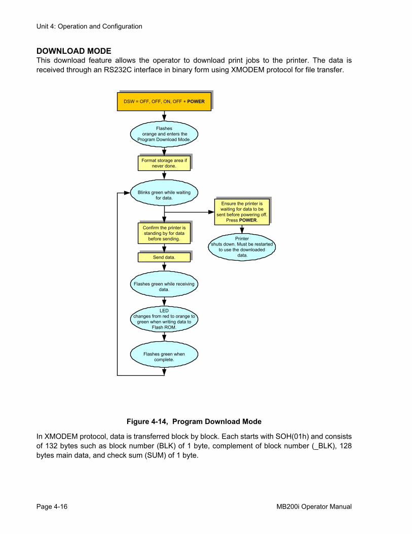
DOWNLOAD MODEThis download feature allows the operator to download print jobs to the printer. The data isreceived through an RS232C interface in binary form using XMODEM protocol for file transfer.
Figure 4-14, Program Download Mode
In XMODEM protocol, data is transferred block by block. Each starts with SOH(01h) and consistsof 132 bytes such as block number (BLK) of 1 byte, complement of block number (_BLK), 128bytes main data, and check sum (SUM) of 1 byte.
DSW = OFF, OFF, ON, OFF + POWER
Flashes orange and enters the
Program Download Mode.
Ensure the printer is waiting for data to be
sent before powering off.Press POWER.
Flashes green while receiving data.
Printer shuts down. Must be restarted
to use the downloaded data.
Blinks green while waiting for data.
LED changes from red to orange to
green when writing data to Flash ROM.
Confirm the printer is standing by for data
before sending.
Send data.
Format storage area if never done.
Flashes green when complete.
Page 4-16 MB200i Operator Manual
Unit 4: Operation and Configuration
The block number starts from 1, and when counting to 255, the number goes back to 0 again. Ifthe block number is [01h], complement of block number becomes [FEh]. In the main data, thesection of data by 128 bytes is stored. SUM is the check sum computed from 128 bytes of maindata.
When downloading data, the format is such that the first 16 bytes are used as header informationand the rest is considered as data. The header information is divided thus: code (4 bytes), startaddress (4 bytes), file size (4 bytes), and reserved area (4 bytes). The remaining optional data isto be stored in Flash ROM.
The basic sequence of XMODEM is to transfer data blocks by individually checking responseblocks. NAK (15h) transmission by the receiving end initiates the sequence, and the sending endsends the first data block after receiving NAK. The receiving end receives and checks this datablock, and then returns ACK (06h) in case of no error or NAK (15h) in case of an error. Thesending end sends the next block when receiving ACK, and resends the same block whenreceiving NAK. This process repeats to the first block. EOT (04h) is sent from the sending end toreceiving end at the end of all data transmission. After receiving EOT (04h), the receiving endreturns ACK to terminate the sequence.
NOTE: The above method is the XMODEM (check sum) option.Select this option in the XMODEM settings on the host side.
MB200i Operator Manual Page 4-17
Unit 4: Operation and Configuration
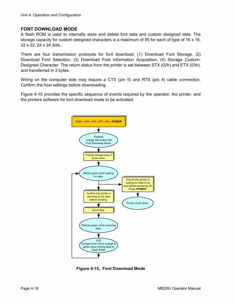
FONT DOWNLOAD MODEA flash ROM is used to internally store and delete font data and custom designed data. Thestorage capacity for custom designed characters is a maximum of 95 for each of type of 16 x 16,22 x 22, 24 x 24 dots.
There are four transmission protocols for font download: (1) Download Font Storage, (2)Download Font Selection, (3) Download Font Information Acquisition, (4) Storage Custom-Designed Character. The return status from the printer is set between STX (02h) and ETX (03h),and transferred in 3 bytes.
Wiring on the computer side may require a CTS (pin 5) and RTS (pin 4) cable connection.Confirm the host settings before downloading.
Figure 4-15 provides the specific sequence of events required by the operator, the printer, andthe printers software for font download mode to be activated.
Figure 4-15, Font Download Mode
DSW = OFF, OFF, OFF, ON + POWER
Flashes orange and enters the Font Download Mode.
Ensure the printer is waiting for data to be
sent before powering off.Press POWER.
Flashes green while receiving data.
Printer shuts down.
Blinks green while waiting for data.
LED changes from red to orange to
green when writing data to Flash ROM.
Confirm the printer is standing by for data
before sending.
Send data.
Format storage area if never done.
Page 4-18 MB200i Operator Manual
Unit 4: Operation and Configuration
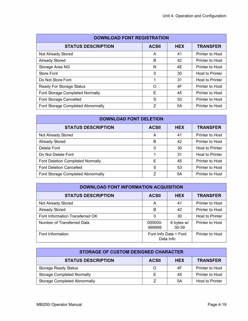
DOWNLOAD FONT REGISTRATION
STATUS DESCRIPTION ACSII HEX TRANSFERNot Already Stored A 41 Printer to HostAlready Stored B 42 Printer to HostStorage Area NG N 4E Printer to HostStore Font 0 30 Host to PrinterDo Not Store Font 1 31 Host to PrinterReady For Storage Status O 4F Printer to HostFont Storage Completed Normally E 45 Printer to HostFont Storage Cancelled S 53 Printer to HostFont Storage Completed Abnormally Z 5A Printer to Host
DOWNLOAD FONT DELETION
STATUS DESCRIPTION ACSII HEX TRANSFERNot Already Stored A 41 Printer to HostAlready Stored B 42 Printer to HostDelete Font 0 30 Host to PrinterDo Not Delete Font 1 31 Host to PrinterFont Deletion Completed Normally E 45 Printer to HostFont Deletion Cancelled S 53 Printer to HostFont Storage Completed Abnormally Z 5A Printer to Host
DOWNLOAD FONT INFORMATION ACQUISITION
STATUS DESCRIPTION ACSII HEX TRANSFERNot Already Stored A 41 Printer to HostAlready Stored B 42 Printer to HostFont Information Transferred OK 0 30 Host to PrinterNumber of Transferred Data 000000-
9999996 bytes w/
30-39Printer to Host
Font Information Font Info Data + Font Data Info
Printer to Host
STORAGE OF CUSTOM DESIGNED CHARACTER
STATUS DESCRIPTION ACSII HEX TRANSFERStorage Ready Status O 4F Printer to HostStorage Completed Normally E 45 Printer to HostStorage Completed Abnormally Z 5A Host to Printer
MB200i Operator Manual Page 4-19
Unit 4: Operation and Configuration
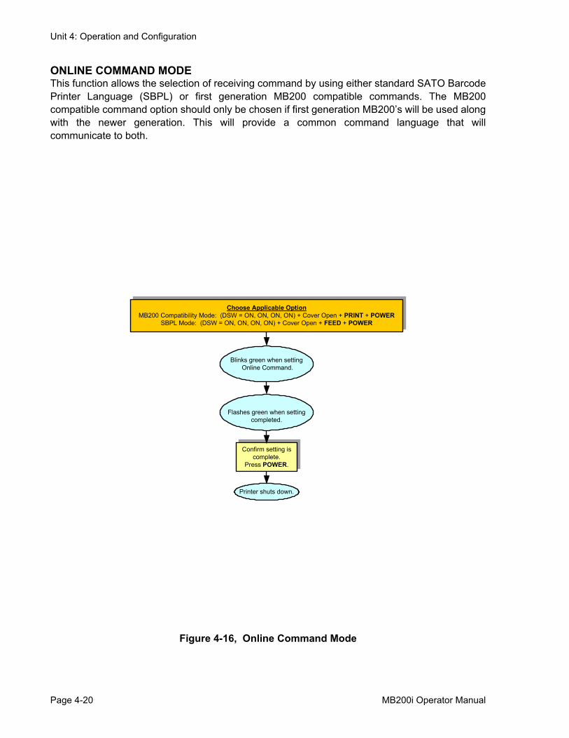
ONLINE COMMAND MODEThis function allows the selection of receiving command by using either standard SATO BarcodePrinter Language (SBPL) or first generation MB200 compatible commands. The MB200compatible command option should only be chosen if first generation MB200’s will be used alongwith the newer generation. This will provide a common command language that willcommunicate to both.
Figure 4-16, Online Command Mode
Choose Applicable OptionMB200 Compatibility Mode: (DSW = ON, ON, ON, ON) + Cover Open + PRINT + POWER
SBPL Mode: (DSW = ON, ON, ON, ON) + Cover Open + FEED + POWER
Blinks green when setting Online Command.
Confirm setting is complete.
Press POWER.
Flashes green when setting completed.
Printer shuts down.
Page 4-20 MB200i Operator Manual
Unit 4: Operation and Configuration
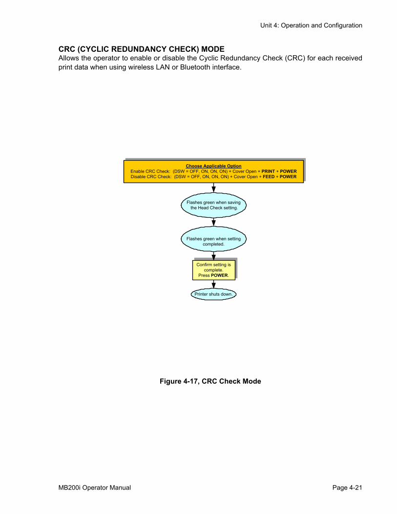
CRC (CYCLIC REDUNDANCY CHECK) MODEAllows the operator to enable or disable the Cyclic Redundancy Check (CRC) for each receivedprint data when using wireless LAN or Bluetooth interface.
Figure 4-17, CRC Check Mode
Choose Applicable OptionEnable CRC Check: (DSW = OFF, ON, ON, ON) + Cover Open + PRINT + POWERDisable CRC Check: (DSW = OFF, ON, ON, ON) + Cover Open + FEED + POWER
Flashes green when saving the Head Check setting.
Confirm setting is complete.
Press POWER.
Flashes green when setting completed.
Printer shuts down.
MB200i Operator Manual Page 4-21
Unit 4: Operation and Configuration
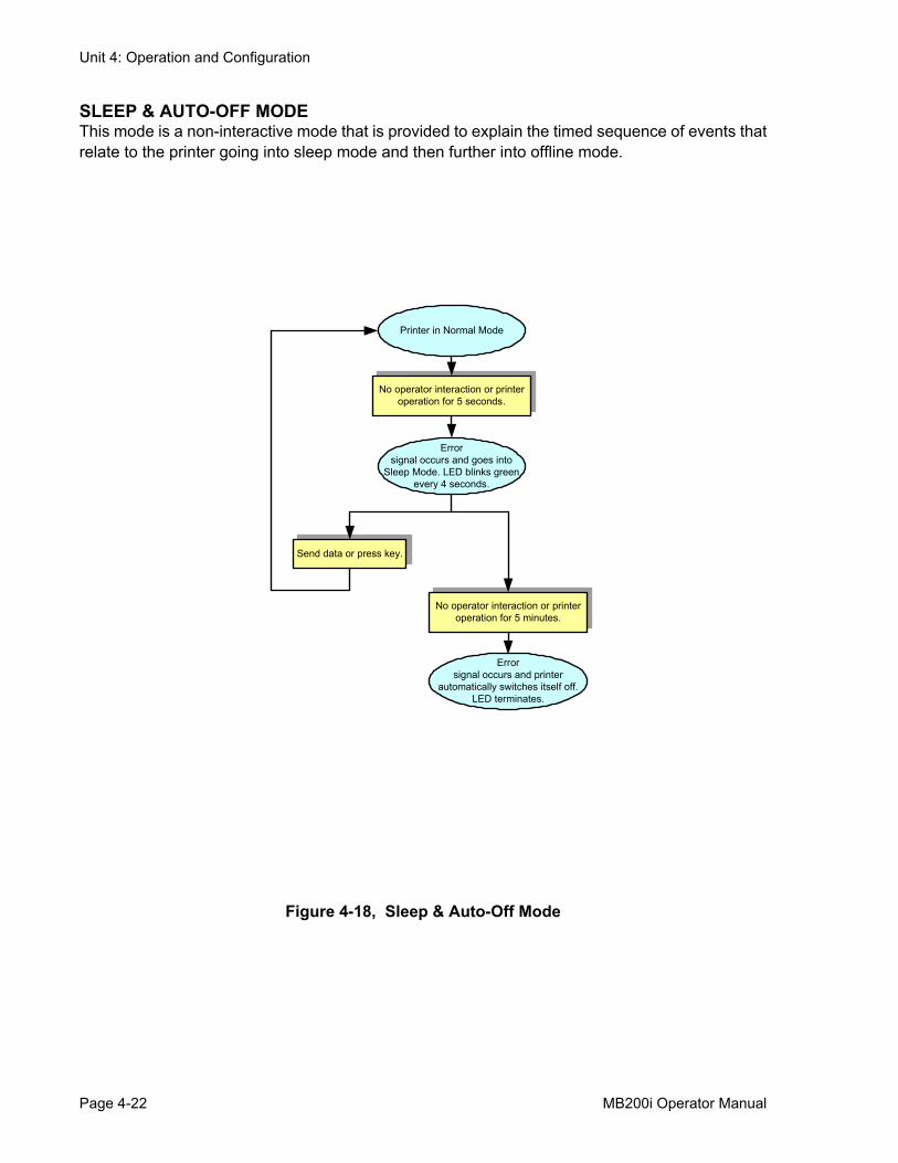
SLEEP & AUTO-OFF MODEThis mode is a non-interactive mode that is provided to explain the timed sequence of events thatrelate to the printer going into sleep mode and then further into offline mode.
Figure 4-18, Sleep & Auto-Off Mode
No operator interaction or printer operation for 5 seconds.
Send data or press key.
Error signal occurs and goes into
Sleep Mode. LED blinks green every 4 seconds.
Printer in Normal Mode
No operator interaction or printer operation for 5 minutes.
Error signal occurs and printer
automatically switches itself off. LED terminates.
Page 4-22 MB200i Operator Manual

Unit 4: Operation and Configuration
PRINTING PROCEDURE
After the proper setup and basic configuration procedures, you are ready to print with theMB200i.
1. Make sure the host computer is ready to transmit data, and ensure that the STATUS LED is litor blinking. (Press the PRINT button to take the printer ONLINE).
Figure 4-19, Pulling the Printed Label Toward You
2. Start the print job from the computer. When printing is finished, pinch either the left or right corner of the printed roll of label(s) and tear it off in the direction of the arrow in the diagram.
NOTES:• The number of sheets you can print is determined by the printer’s mode (continuous or dis-
pense mode).• When printing linerless labels and you have torn the labels at a wrong place, stop the printing
and follow the instructions on the next page to correct the print job.
123456 7abcdefg
1234567abcdefg
1234567abcdefg
MB200i Operator Manual Page 4-23
Unit 4: Operation and Configuration
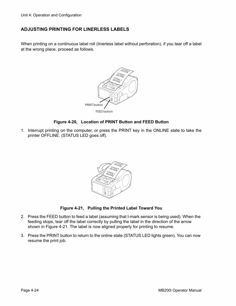
ADJUSTING PRINTING FOR LINERLESS LABELS
When printing on a continuous label roll (linerless label without perforation), if you tear off a labelat the wrong place, proceed as follows.
Figure 4-20, Location of PRINT Button and FEED Button
1. Interrupt printing on the computer, or press the PRINT key in the ONLINE state to take theprinter OFFLINE. (STATUS LED goes off).
Figure 4-21, Pulling the Printed Label Toward You
2. Press the FEED button to feed a label (assuming that I-mark sensor is being used). When the feeding stops, tear off the label correctly by pulling the label in the direction of the arrow shown in Figure 4-21. The label is now aligned properly for printing to resume.
3. Press the PRINT button to return to the online state (STATUS LED lights green). You can now resume the print job.
FEED button
PRINT button
123456 7abcdefg
1234567abcdefg
1234567abcdefg
123456 7abcdefg
1234567abcdefg
1234567abcdefg
Page 4-24 MB200i Operator Manual
Unit 4: Operation and Configuration
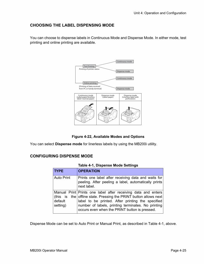
CHOOSING THE LABEL DISPENSING MODE
You can choose to dispense labels in Continuous Mode and Dispense Mode. In either mode, testprinting and online printing are available.
Figure 4-22, Available Modes and Options
You can select Dispense mode for linerless labels by using the MB200i utility.
CONFIGURING DISPENSE MODE
Table 4-1, Dispense Mode Settings
Dispense Mode can be set to Auto Print or Manual Print, as described in Table 4-1, above.
TYPE OPERATION
Auto Print Prints one label after receiving data and waits forpeeling. After peeling a label, automatically printsnext label.
Manual Print(this is thedefaultsetting)
Prints one label after receiving data and entersoffline state. Pressing the PRINT button allows nextlabel to be printed. After printing the specifiednumber of labels, printing terminates. No printingoccurs even when the PRINT button is pressed.
Continuous mode
Test PrintingPrinting of printer status
Dispense mode
Continuous mode
Online printing
(Printing of data receivedfrom PC or handy terminal) Dispense mode
1234567abcdefg
1234567abcdefg
1234567abcdefg
1234567abcdefg
1234567abcdefg
Continuous mode(Label paper/linerless label/ Journal paper)
Dispense mode(Label paper)
Dispense mode(Linerless label with
perforation)
MB200i Operator Manual Page 4-25
Unit 4: Operation and Configuration
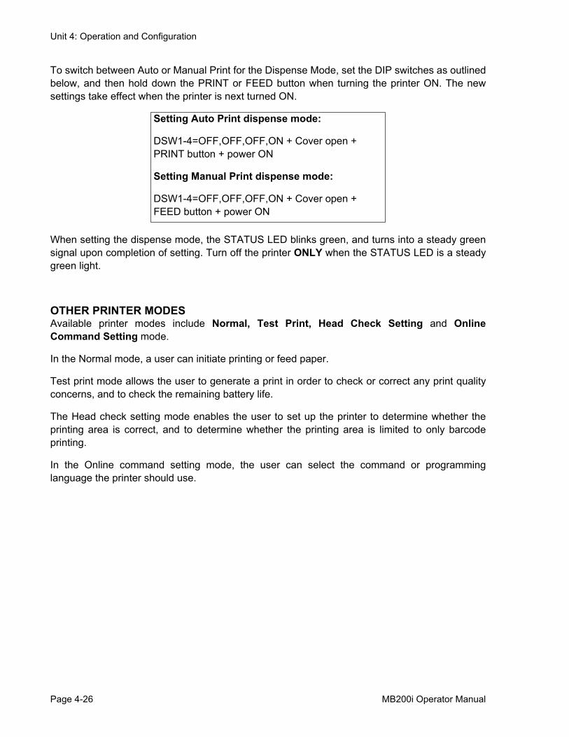
To switch between Auto or Manual Print for the Dispense Mode, set the DIP switches as outlinedbelow, and then hold down the PRINT or FEED button when turning the printer ON. The newsettings take effect when the printer is next turned ON.
When setting the dispense mode, the STATUS LED blinks green, and turns into a steady greensignal upon completion of setting. Turn off the printer ONLY when the STATUS LED is a steadygreen light.
OTHER PRINTER MODESAvailable printer modes include Normal, Test Print, Head Check Setting and OnlineCommand Setting mode.
In the Normal mode, a user can initiate printing or feed paper.
Test print mode allows the user to generate a print in order to check or correct any print qualityconcerns, and to check the remaining battery life.
The Head check setting mode enables the user to set up the printer to determine whether theprinting area is correct, and to determine whether the printing area is limited to only barcodeprinting.
In the Online command setting mode, the user can select the command or programminglanguage the printer should use.
Setting Auto Print dispense mode:
DSW1-4=OFF,OFF,OFF,ON + Cover open + PRINT button + power ON
Setting Manual Print dispense mode:
DSW1-4=OFF,OFF,OFF,ON + Cover open + FEED button + power ON
Page 4-26 MB200i Operator Manual
Unit 4: Operation and Configuration
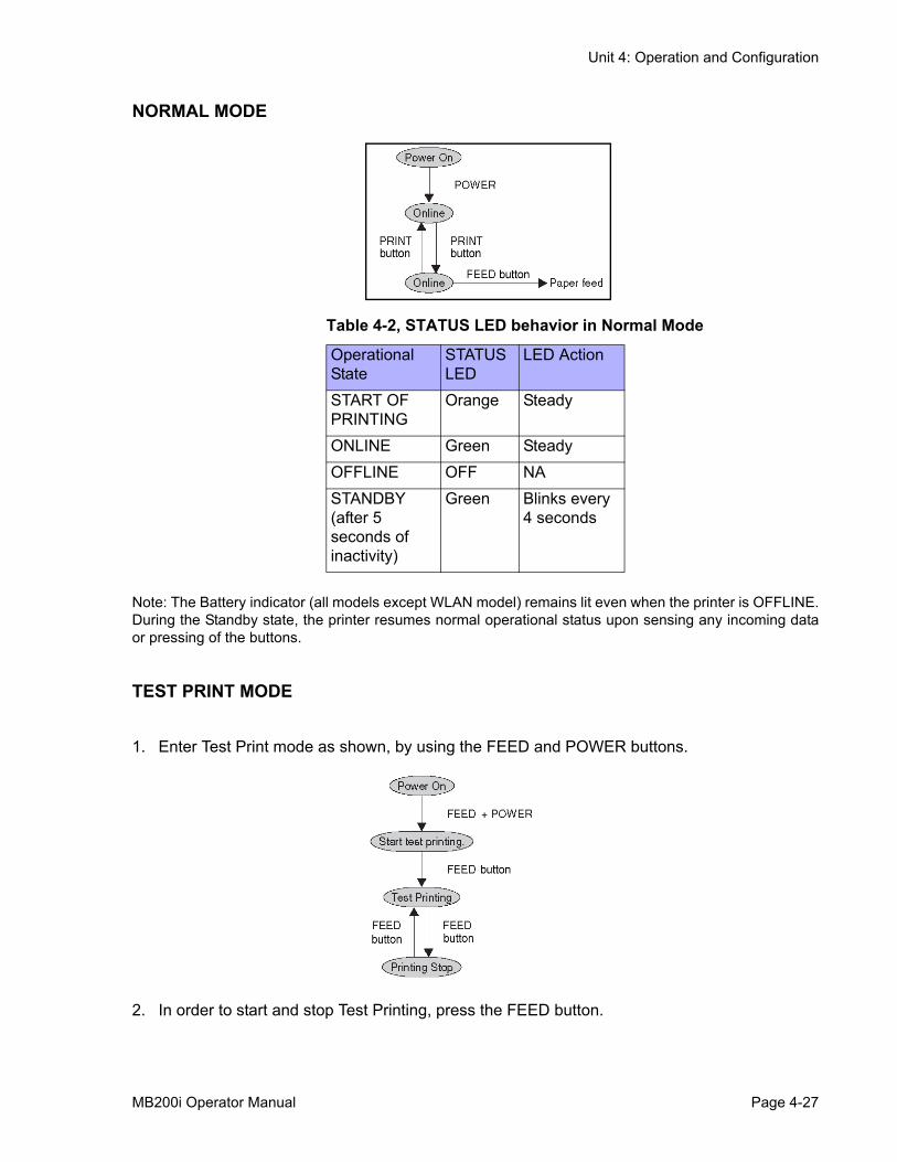
NORMAL MODE
Note: The Battery indicator (all models except WLAN model) remains lit even when the printer is OFFLINE.During the Standby state, the printer resumes normal operational status upon sensing any incoming dataor pressing of the buttons.
TEST PRINT MODE
1. Enter Test Print mode as shown, by using the FEED and POWER buttons.
2. In order to start and stop Test Printing, press the FEED button.
Table 4-2, STATUS LED behavior in Normal Mode
OperationalState
STATUSLED
LED Action
START OF PRINTING
Orange Steady
ONLINE Green SteadyOFFLINE OFF NASTANDBY (after 5 seconds of inactivity)
Green Blinks every 4 seconds
MB200i Operator Manual Page 4-27
Unit 4: Operation and Configuration
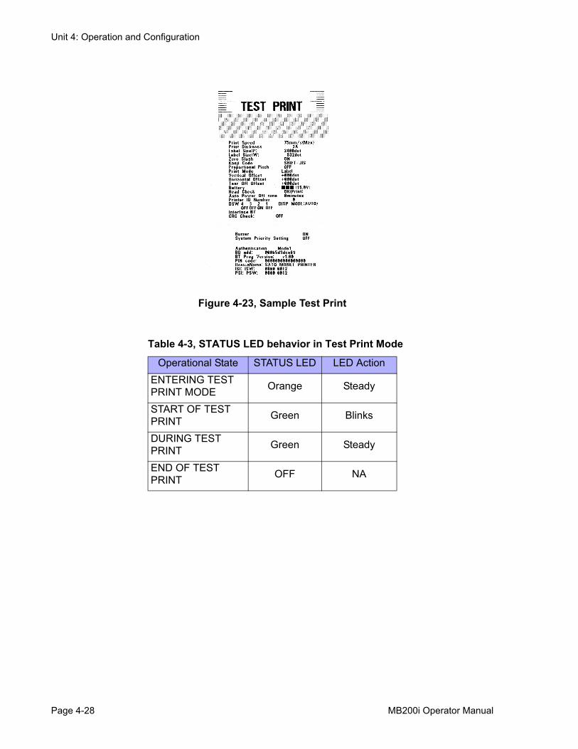
Figure 4-23, Sample Test Print
Table 4-3, STATUS LED behavior in Test Print Mode
Operational State STATUS LED LED ActionENTERING TEST PRINT MODE Orange Steady
START OF TEST PRINT Green Blinks
DURING TEST PRINT Green Steady
END OF TEST PRINT OFF NA
Page 4-28 MB200i Operator Manual
Unit 4: Operation and Configuration
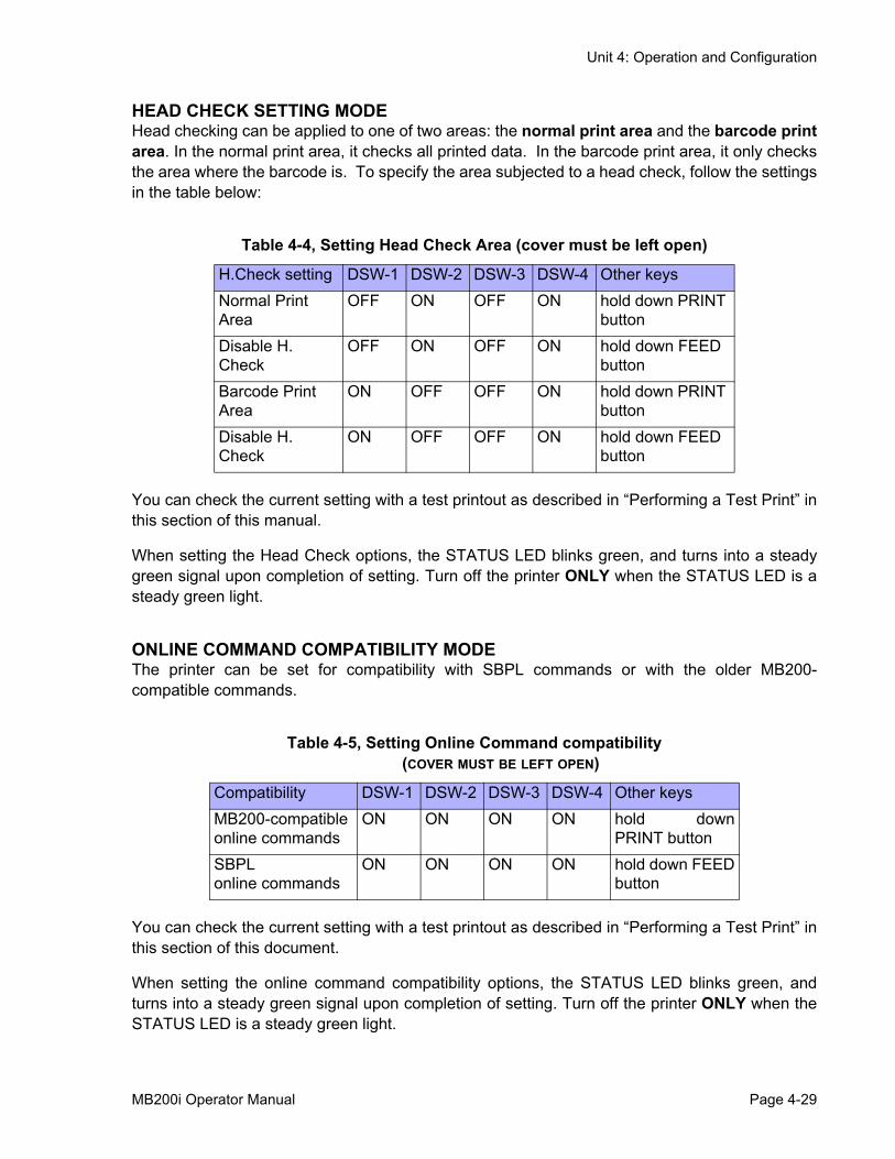
HEAD CHECK SETTING MODEHead checking can be applied to one of two areas: the normal print area and the barcode printarea. In the normal print area, it checks all printed data. In the barcode print area, it only checksthe area where the barcode is. To specify the area subjected to a head check, follow the settingsin the table below:
You can check the current setting with a test printout as described in “Performing a Test Print” inthis section of this manual.
When setting the Head Check options, the STATUS LED blinks green, and turns into a steadygreen signal upon completion of setting. Turn off the printer ONLY when the STATUS LED is asteady green light.
ONLINE COMMAND COMPATIBILITY MODEThe printer can be set for compatibility with SBPL commands or with the older MB200-compatible commands.
You can check the current setting with a test printout as described in “Performing a Test Print” inthis section of this document.
When setting the online command compatibility options, the STATUS LED blinks green, andturns into a steady green signal upon completion of setting. Turn off the printer ONLY when theSTATUS LED is a steady green light.
Table 4-4, Setting Head Check Area (cover must be left open)
H.Check setting DSW-1 DSW-2 DSW-3 DSW-4 Other keysNormal Print Area
OFF ON OFF ON hold down PRINT button
Disable H. Check
OFF ON OFF ON hold down FEED button
Barcode Print Area
ON OFF OFF ON hold down PRINT button
Disable H. Check
ON OFF OFF ON hold down FEED button
Table 4-5, Setting Online Command compatibility(COVER MUST BE LEFT OPEN)
Compatibility DSW-1 DSW-2 DSW-3 DSW-4 Other keysMB200-compatible online commands
ON ON ON ON hold downPRINT button
SBPLonline commands
ON ON ON ON hold down FEEDbutton
MB200i Operator Manual Page 4-29
Unit 4: Operation and Configuration
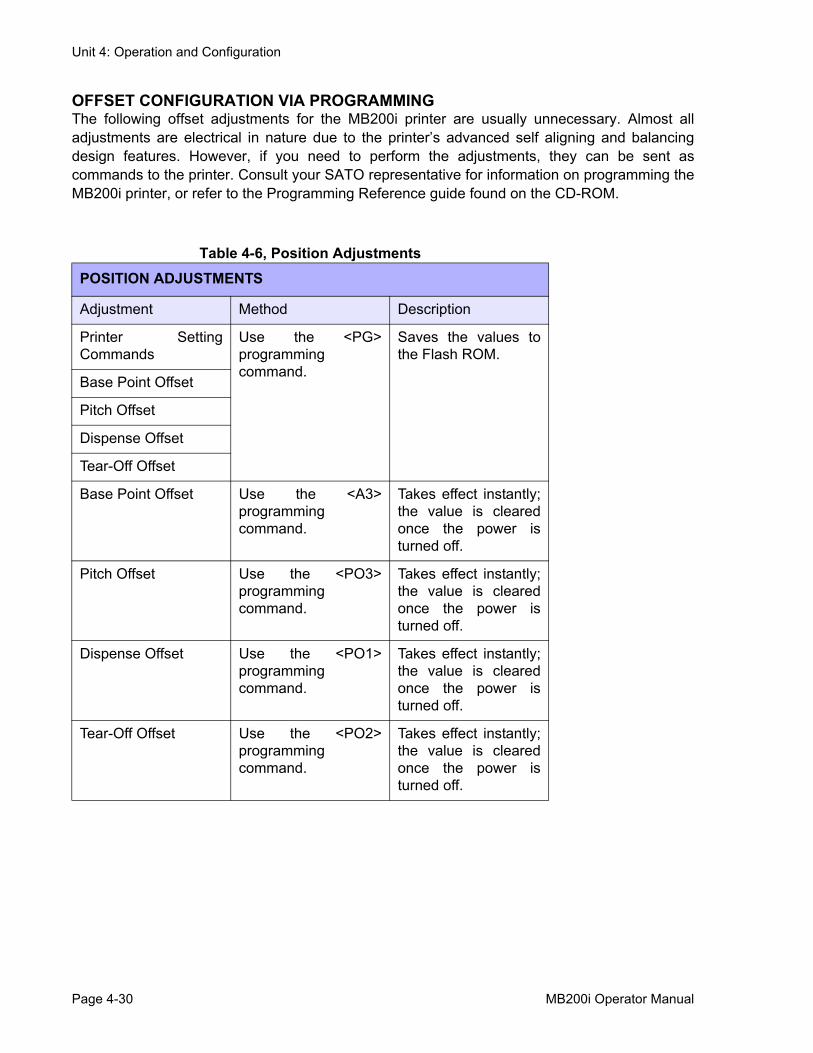
OFFSET CONFIGURATION VIA PROGRAMMINGThe following offset adjustments for the MB200i printer are usually unnecessary. Almost alladjustments are electrical in nature due to the printer’s advanced self aligning and balancingdesign features. However, if you need to perform the adjustments, they can be sent ascommands to the printer. Consult your SATO representative for information on programming theMB200i printer, or refer to the Programming Reference guide found on the CD-ROM.
Table 4-6, Position AdjustmentsPOSITION ADJUSTMENTS
Adjustment Method Description
Printer SettingCommands
Use the <PG>programmingcommand.
Saves the values tothe Flash ROM.
Base Point Offset
Pitch Offset
Dispense Offset
Tear-Off Offset
Base Point Offset Use the <A3>programmingcommand.
Takes effect instantly;the value is clearedonce the power isturned off.
Pitch Offset Use the <PO3>programmingcommand.
Takes effect instantly;the value is clearedonce the power isturned off.
Dispense Offset Use the <PO1>programmingcommand.
Takes effect instantly;the value is clearedonce the power isturned off.
Tear-Off Offset Use the <PO2>programmingcommand.
Takes effect instantly;the value is clearedonce the power isturned off.
Page 4-30 MB200i Operator Manual
Unit 5: Operating Modes
OPERATING MODES• Operating Modes
MB200i Operator Manual Page 5-1
Unit 5: Operating Modes
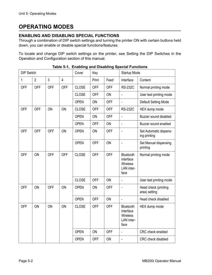
OPERATING MODESENABLING AND DISABLING SPECIAL FUNCTIONSThrough a combination of DIP switch settings and turning the printer ON with certain buttons helddown, you can enable or disable special functions/features.
To locate and change DIP switch settings on the printer, see Setting the DIP Switches in theOperation and Configuration section of this manual.
Table 5-1, Enabling and Disabling Special FunctionsDIP Switch Cover Key Startup Mode
1 2 3 4 Print Feed Interface Content
OFF OFF OFF OFF CLOSE OFF OFF RS-232C Normal printing mode
CLOSE OFF ON - User test printing mode
OPEN ON OFF - Default Setting Mode
OFF OFF ON ON CLOSE OFF OFF RS-232C HEX dump mode
OPEN ON OFF - Buzzer sound disabled
OPEN OFF ON - Buzzer sound enabled
OFF OFF OFF ON OPEN ON OFF - Set Automatic dispens-ing printing
OPEN OFF ON - Set Manual dispensing printing
OFF ON OFF OFF CLOSE OFF OFF Bluetooth interface Wireless LAN inter-face
Normal printing mode
CLOSE OFF ON - User test printing mode
OFF ON OFF ON OPEN ON OFF - Head check (printing area) setting
OPEN OFF ON - Head check disabled
OFF ON ON ON CLOSE OFF OFF Bluetooth interface Wireless LAN inter-face
HEX dump mode
OPEN ON OFF - CRC check enabled
OPEN OFF ON - CRC check disabled
Page 5-2 MB200i Operator Manual
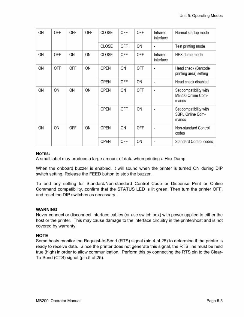
Unit 5: Operating Modes
NOTES: A small label may produce a large amount of data when printing a Hex Dump.
When the onboard buzzer is enabled, it will sound when the printer is turned ON during DIPswitch setting. Release the FEED button to stop the buzzer.
To end any setting for Standard/Non-standard Control Code or Dispense Print or OnlineCommand compatibility, confirm that the STATUS LED is lit green. Then turn the printer OFF,and reset the DIP switches as necessary.
WARNINGNever connect or disconnect interface cables (or use switch box) with power applied to either thehost or the printer. This may cause damage to the interface circuitry in the printer/host and is notcovered by warranty.
NOTESome hosts monitor the Request-to-Send (RTS) signal (pin 4 of 25) to determine if the printer isready to receive data. Since the printer does not generate this signal, the RTS line must be heldtrue (high) in order to allow communication. Perform this by connecting the RTS pin to the Clear-To-Send (CTS) signal (pin 5 of 25).
ON OFF OFF OFF CLOSE OFF OFF Infrared interface
Normal startup mode
CLOSE OFF ON - Test printing mode
ON OFF ON ON CLOSE OFF OFF Infrared interface
HEX dump mode
ON OFF OFF ON OPEN ON OFF - Head check (Barcode printing area) setting
OPEN OFF ON - Head check disabled
ON ON ON ON OPEN ON OFF - Set compatibility with MB200 Online Com-mands
OPEN OFF ON - Set compatibility with SBPL Online Com-mands
ON ON OFF ON OPEN ON OFF - Non-standard Control codes
OPEN OFF ON - Standard Control codes
MB200i Operator Manual Page 5-3

Unit 5: Operating Modes
This page intentionally left blank.
Page 5-4 MB200i Operator Manual

Unit 6: Cleaning and Maintenance
CLEANING AND MAINTENANCE
• Cleaning and Maintenance
MB200i Operator Manual Page 6-1
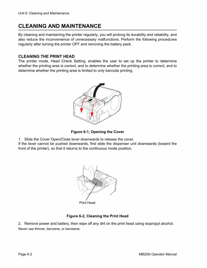
Unit 6: Cleaning and Maintenance
CLEANING AND MAINTENANCEBy cleaning and maintaining the printer regularly, you will prolong its durability and reliability, andalso reduce the inconvenience of unnecessary malfunctions. Perform the following proceduresregularly after turning the printer OFF and removing the battery pack.
CLEANING THE PRINT HEADThe printer mode, Head Check Setting, enables the user to set up the printer to determinewhether the printing area is correct, and to determine whether the printing area is correct, and todetermine whether the printing area is limited to only barcode printing.
Figure 6-1, Opening the Cover
1. Slide the Cover Open/Close lever downwards to release the cover. If the lever cannot be pushed downwards, first slide the dispenser unit downwards (toward thefront of the printer), so that it returns to the continuous mode position.
Figure 6-2, Cleaning the Print Head
2. Remove power and battery, then wipe off any dirt on the print head using isopropyl alcohol.Never use thinner, benzene, or kerosene.
Print Head
Page 6-2 MB200i Operator Manual
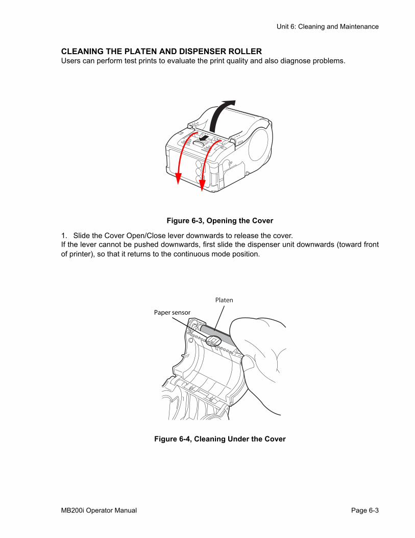
Unit 6: Cleaning and Maintenance
CLEANING THE PLATEN AND DISPENSER ROLLERUsers can perform test prints to evaluate the print quality and also diagnose problems.
Figure 6-3, Opening the Cover
1. Slide the Cover Open/Close lever downwards to release the cover. If the lever cannot be pushed downwards, first slide the dispenser unit downwards (toward frontof printer), so that it returns to the continuous mode position.
Figure 6-4, Cleaning Under the Cover
Platen
Paper sensor
MB200i Operator Manual Page 6-3

Unit 6: Cleaning and Maintenance
Figure 6-5, Cleaning the Dispenser Roller
2. Wipe off any dirt using isopropyl alcohol.Never use thinner, benzene, or kerosene.
Dispense roller
Page 6-4 MB200i Operator Manual

Unit 7: Troubleshooting
TROUBLESHOOTING• Troubleshooting
MB200i Operator Manual -
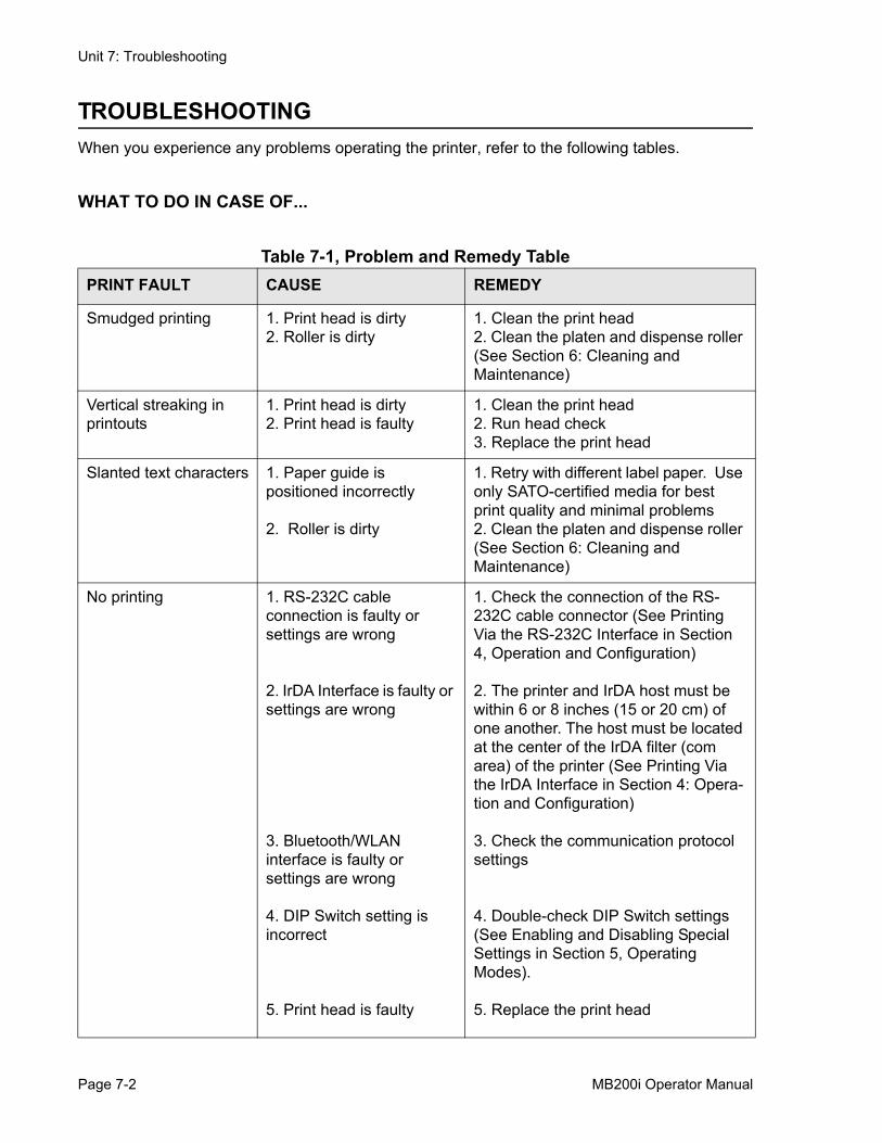
Unit 7: Troubleshooting
TROUBLESHOOTINGWhen you experience any problems operating the printer, refer to the following tables.
WHAT TO DO IN CASE OF...
Table 7-1, Problem and Remedy TablePRINT FAULT CAUSE REMEDY
Smudged printing 1. Print head is dirty2. Roller is dirty
1. Clean the print head2. Clean the platen and dispense roller (See Section 6: Cleaning and Maintenance)
Vertical streaking in printouts
1. Print head is dirty2. Print head is faulty
1. Clean the print head2. Run head check3. Replace the print head
Slanted text characters 1. Paper guide is positioned incorrectly
2. Roller is dirty
1. Retry with different label paper. Use only SATO-certified media for best print quality and minimal problems2. Clean the platen and dispense roller (See Section 6: Cleaning and Maintenance)
No printing 1. RS-232C cable connection is faulty or settings are wrong
2. IrDA Interface is faulty or settings are wrong
3. Bluetooth/WLAN interface is faulty or settings are wrong
4. DIP Switch setting is incorrect
5. Print head is faulty
1. Check the connection of the RS-232C cable connector (See Printing Via the RS-232C Interface in Section 4, Operation and Configuration)
2. The printer and IrDA host must be within 6 or 8 inches (15 or 20 cm) of one another. The host must be located at the center of the IrDA filter (com area) of the printer (See Printing Via the IrDA Interface in Section 4: Opera-tion and Configuration)
3. Check the communication protocol settings
4. Double-check DIP Switch settings (See Enabling and Disabling Special Settings in Section 5, Operating Modes).
5. Replace the print head
Page 7-2 MB200i Operator Manual
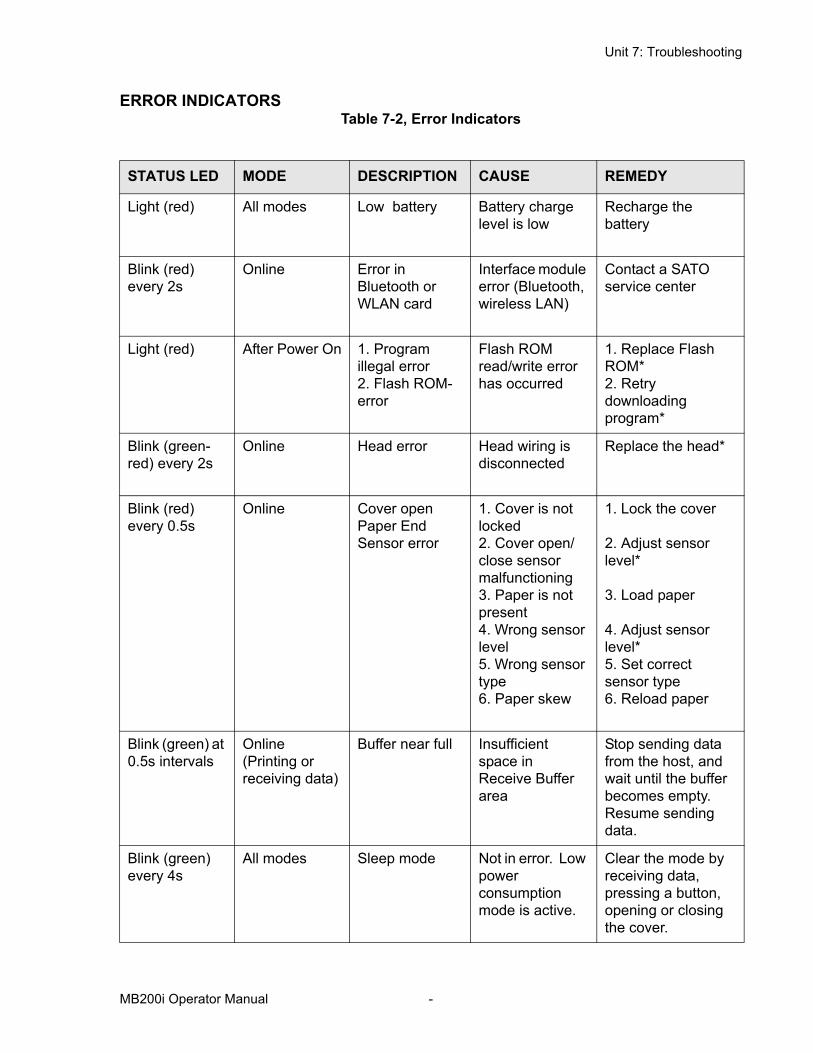
Unit 7: Troubleshooting
ERROR INDICATORSTable 7-2, Error Indicators
STATUS LED MODE DESCRIPTION CAUSE REMEDY
Light (red) All modes Low battery Battery charge level is low
Recharge the battery
Blink (red) every 2s
Online Error in Bluetooth or WLAN card
Interface module error (Bluetooth, wireless LAN)
Contact a SATO service center
Light (red) After Power On 1. Program illegal error2. Flash ROM-error
Flash ROM read/write error has occurred
1. Replace Flash ROM*2. Retry downloading program*
Blink (green-red) every 2s
Online Head error Head wiring is disconnected
Replace the head*
Blink (red) every 0.5s
Online Cover open Paper End Sensor error
1. Cover is not locked2. Cover open/close sensor malfunctioning3. Paper is not present4. Wrong sensor level5. Wrong sensor type6. Paper skew
1. Lock the cover
2. Adjust sensor level*
3. Load paper
4. Adjust sensor level*5. Set correct sensor type6. Reload paper
Blink (green) at 0.5s intervals
Online (Printing or receiving data)
Buffer near full Insufficient space in Receive Buffer area
Stop sending data from the host, and wait until the buffer becomes empty. Resume sending data.
Blink (green) every 4s
All modes Sleep mode Not in error. Low power consumption mode is active.
Clear the mode by receiving data, pressing a button, opening or closing the cover.
MB200i Operator Manual -
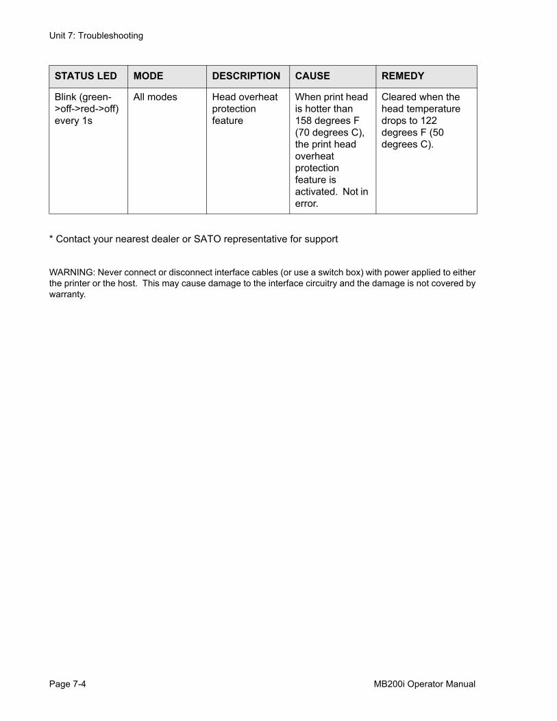
Unit 7: Troubleshooting
* Contact your nearest dealer or SATO representative for support
WARNING: Never connect or disconnect interface cables (or use a switch box) with power applied to eitherthe printer or the host. This may cause damage to the interface circuitry and the damage is not covered bywarranty.
Blink (green->off->red->off) every 1s
All modes Head overheat protection feature
When print head is hotter than 158 degrees F (70 degrees C), the print head overheat protection feature is activated. Not in error.
Cleared when the head temperature drops to 122 degrees F (50 degrees C).
STATUS LED MODE DESCRIPTION CAUSE REMEDY
Page 7-4 MB200i Operator Manual
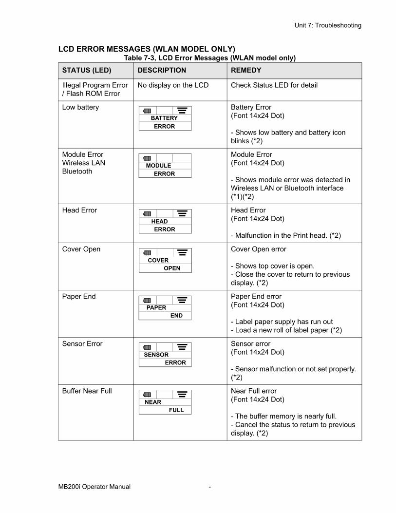
Unit 7: Troubleshooting
LCD ERROR MESSAGES (WLAN MODEL ONLY)Table 7-3, LCD Error Messages (WLAN model only)
STATUS (LED) DESCRIPTION REMEDY
Illegal Program Error / Flash ROM Error
No display on the LCD Check Status LED for detail
Low battery Battery Error(Font 14x24 Dot)
- Shows low battery and battery icon blinks (*2)
Module Error Wireless LAN Bluetooth
Module Error(Font 14x24 Dot)
- Shows module error was detected in Wireless LAN or Bluetooth interface (*1)(*2)
Head Error Head Error(Font 14x24 Dot)
- Malfunction in the Print head. (*2)
Cover Open Cover Open error
- Shows top cover is open.- Close the cover to return to previous display. (*2)
Paper End Paper End error(Font 14x24 Dot)
- Label paper supply has run out- Load a new roll of label paper (*2)
Sensor Error Sensor error(Font 14x24 Dot)
- Sensor malfunction or not set properly. (*2)
Buffer Near Full Near Full error(Font 14x24 Dot)
- The buffer memory is nearly full.- Cancel the status to return to previous display. (*2)
BATTERYERROR
MODULEERROR
HEADERROR
COVEROPEN
PAPEREND
SENSORERROR
NEARFULL
MB200i Operator Manual -
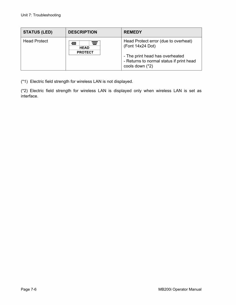
Unit 7: Troubleshooting
(*1) Electric field strength for wireless LAN is not displayed.
(*2) Electric field strength for wireless LAN is displayed only when wireless LAN is set asinterface.
Head Protect Head Protect error (due to overheat)(Font 14x24 Dot)
- The print head has overheated- Returns to normal status if print head cools down (*2)
STATUS (LED) DESCRIPTION REMEDY
HEADPROTECT
Page 7-6 MB200i Operator Manual

Unit 8: Sato Contacts
SATO CONTACTS• SATO Group of Companies
MB200i Operator Manual Page 8-1
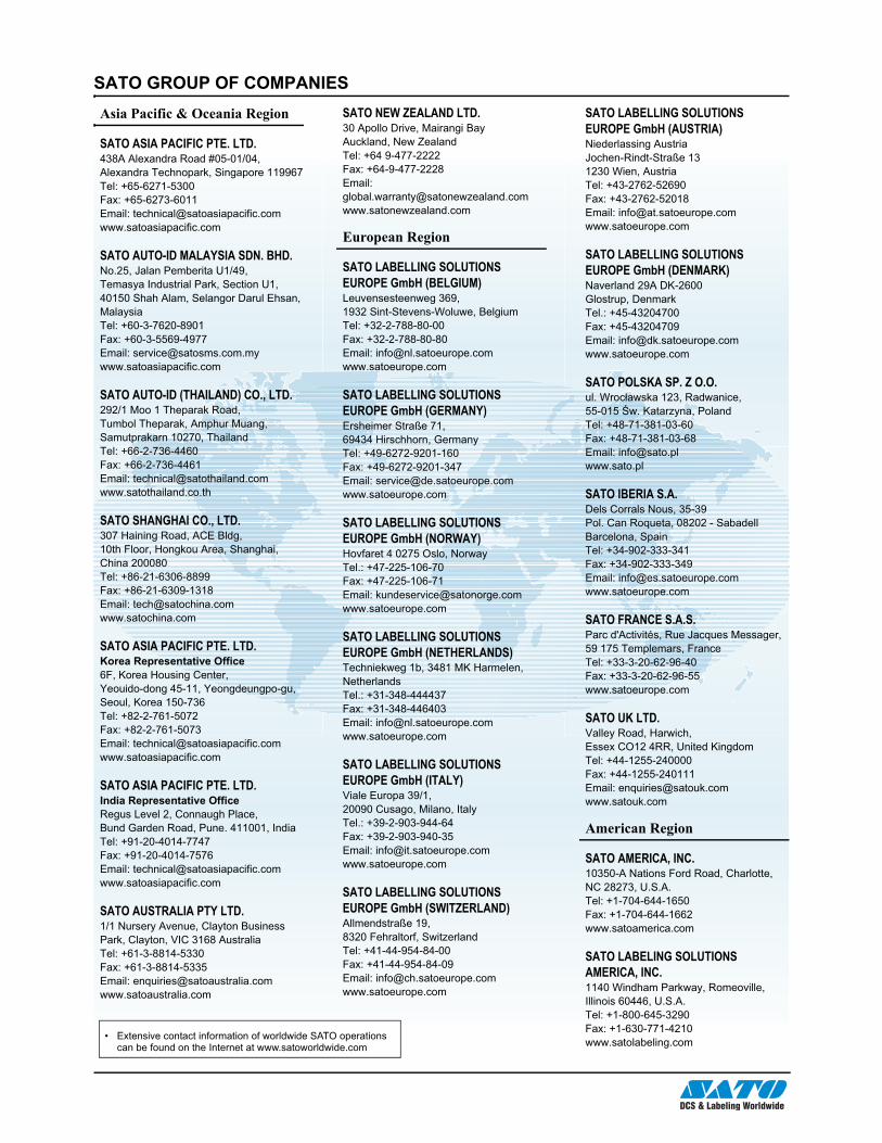
Unit 8: Sato Contacts
Page 8-2 MB200i Operator Manual
SATO GROUP OF COMPANIES
• Extensive contact information of worldwide SATO operations can be found on the Internet at www.satoworldwide.com
Asia Pacific & Oceania Region
SATO ASIA PACIFIC PTE. LTD.438A Alexandra Road #05-01/04, Alexandra Technopark, Singapore 119967Tel: +65-6271-5300Fax: +65-6273-6011Email: [email protected]
SATO AUTO-ID MALAYSIA SDN. BHD.No.25, Jalan Pemberita U1/49, Temasya Industrial Park, Section U1, 40150 Shah Alam, Selangor Darul Ehsan, MalaysiaTel: +60-3-7620-8901Fax: +60-3-5569-4977 Email: [email protected]
SATO AUTO-ID (THAILAND) CO., LTD.292/1 Moo 1 Theparak Road, Tumbol Theparak, Amphur Muang, Samutprakarn 10270, ThailandTel: +66-2-736-4460Fax: +66-2-736-4461Email: [email protected]
SATO SHANGHAI CO., LTD.307 Haining Road, ACE Bldg, 10th Floor, Hongkou Area, Shanghai, China 200080Tel: +86-21-6306-8899Fax: +86-21-6309-1318Email: [email protected]
SATO ASIA PACIFIC PTE. LTD.Korea Representative Office6F, Korea Housing Center,Yeouido-dong 45-11, Yeongdeungpo-gu, Seoul, Korea 150-736Tel: +82-2-761-5072Fax: +82-2-761-5073Email: [email protected]
SATO ASIA PACIFIC PTE. LTD.India Representative OfficeRegus Level 2, Connaugh Place, Bund Garden Road, Pune. 411001, IndiaTel: +91-20-4014-7747Fax: +91-20-4014-7576Email: [email protected]
SATO AUSTRALIA PTY LTD.1/1 Nursery Avenue, Clayton Business Park, Clayton, VIC 3168 AustraliaTel: +61-3-8814-5330Fax: +61-3-8814-5335Email: [email protected]
SATO NEW ZEALAND LTD. 30 Apollo Drive, Mairangi BayAuckland, New ZealandTel: +64 9-477-2222 Fax: +64-9-477-2228Email: [email protected]
European Region
SATO LABELLING SOLUTIONS EUROPE GmbH (BELGIUM)Leuvensesteenweg 369, 1932 Sint-Stevens-Woluwe, BelgiumTel: +32-2-788-80-00Fax: +32-2-788-80-80Email: [email protected]
SATO LABELLING SOLUTIONS EUROPE GmbH (GERMANY)Ersheimer Straße 71, 69434 Hirschhorn, GermanyTel: +49-6272-9201-160Fax: +49-6272-9201-347Email: [email protected]
SATO LABELLING SOLUTIONS EUROPE GmbH (NORWAY)Hovfaret 4 0275 Oslo, NorwayTel.: +47-225-106-70Fax: +47-225-106-71Email: [email protected]
SATO LABELLING SOLUTIONS EUROPE GmbH (NETHERLANDS)Techniekweg 1b, 3481 MK Harmelen, NetherlandsTel.: +31-348-444437Fax: +31-348-446403Email: [email protected]
SATO LABELLING SOLUTIONS EUROPE GmbH (ITALY)Viale Europa 39/1,20090 Cusago, Milano, ItalyTel.: +39-2-903-944-64Fax: +39-2-903-940-35Email: [email protected]
SATO LABELLING SOLUTIONS EUROPE GmbH (SWITZERLAND)Allmendstraße 19,8320 Fehraltorf, SwitzerlandTel: +41-44-954-84-00Fax: +41-44-954-84-09Email: [email protected]
SATO LABELLING SOLUTIONS EUROPE GmbH (AUSTRIA)Niederlassing Austria Jochen-Rindt-Straße 13 1230 Wien, AustriaTel: +43-2762-52690Fax: +43-2762-52018Email: [email protected]
SATO LABELLING SOLUTIONS EUROPE GmbH (DENMARK)Naverland 29A DK-2600 Glostrup, DenmarkTel.: +45-43204700Fax: +45-43204709Email: [email protected]
SATO POLSKA SP. Z O.O.ul. Wroc�awska 123, Radwanice,55-015 �w. Katarzyna, Poland Tel: +48-71-381-03-60 Fax: +48-71-381-03-68Email: [email protected]
SATO IBERIA S.A.Dels Corrals Nous, 35-39Pol. Can Roqueta, 08202 - SabadellBarcelona, SpainTel: +34-902-333-341Fax: +34-902-333-349Email: [email protected]
SATO FRANCE S.A.S. Parc d'Activités, Rue Jacques Messager,59 175 Templemars, FranceTel: +33-3-20-62-96-40 Fax: +33-3-20-62-96-55 www.satoeurope.com
SATO UK LTD.Valley Road, Harwich, Essex CO12 4RR, United KingdomTel: +44-1255-240000Fax: +44-1255-240111Email: [email protected]
American Region
SATO AMERICA, INC.10350-A Nations Ford Road, Charlotte, NC 28273, U.S.A.Tel: +1-704-644-1650Fax: +1-704-644-1662www.satoamerica.com
SATO LABELING SOLUTIONS AMERICA, INC. 1140 Windham Parkway, Romeoville, Illinois 60446, U.S.A.Tel: +1-800-645-3290 Fax: +1-630-771-4210www.satolabeling.com