Embed Size (px)
Citation preview
00e™series VR1816Instruction Sheet
102-499
SUPERSEDES: September 30, 2014 EFFECTIVE: February 11, 2016 Plant ID no. 001-4230
Infinitely Variable Speed, ECM High-Efficiency Circulator
DESCRIPTION:
The 00e™series VR1816 circulator is an infinitely variable speed wet rotor circulator withan ECM, permanent magnet motor. Operating modes include infinitely adjustable fixedspeed or self-adjusting proportional or constant pressure variable speed. Its high effi-ciency motor reduces power consumption by up to 85% compared to equivalent AC per-manent split capacitor circulators.
APPLICATION:
• Maximum operating pressure: 125 psi (8.6 bar)
• Maximum water temperature: 230°F (110ºC)
• Electrical specifications:
Voltage: 110-120V, 50/60 Hz, single phase
Maximum operating power: 44W
Maximum amp rating: 0.54
• Equipped with a cast iron casing and should be used for closed loop systems only.
• Taco circulator pumps are for indoor use only – employer uniquement a l’interieur.
• Acceptable for use with water or maximum of 50% water/glycol solution.
FEATURES:
• 3 operating modes:- Fixed speed ( ) - infinitely adjustable MIn/MAx settings- Constant pressure ( ), variable speed - 3 constant pressure differential curves (5, 10, or 15 maximum feet of head)- Proportional pressure ( ), variable speed - 3 variable pressure differential curves (High, Med, or Low)
• Multi-color LED display showing operating mode and error code diagnostics.• Use with a Taco ZVC Zone Valve Control or SR Switching Relay for On/OFF operation.• nut capture feature on flanges for easier fit up.• Dual electrical knockouts and 6” stranded wire leads for easy wiring.• Double insulated - no ground wire required.• Whisper quiet operation.• BIO Barrier® protects the pump from system contaminants.• SureStart automatic unblocking and air purging mode.• Optional 2-way flange model for easy fit-up to any flange orientation.• Integral Flow Check (IFC®) included - Field installed.
INSTALLATION:
WARNING: Do not use in swimming pool or spa areas. Pump has not been investigated for these applications.
AVERTISSEMENT: Ne pas utiliser dans une piscine ou un spa. La pompe n'a pas été étudiée pour ces applications.
CAUTION: The addition of petroleum based fluids or certain chemical additives to systems using TACO equipment voids the warranty.Consult factory for fluid compatibility.
ATTENTION: L'ajout de liquides à base de pétrole ou de certains additifs chimiques à des systèmes utilisant un équipement TACO annulela garantie. Consultez le fabricant pour connaître la compatibilité de liquides.
CAUTION: Installations at elevations over 5000 feet must have higher fill pressure of 20 psi minimum to prevent pump cavitation and flash-ing. Premature failure may result. Adjust expansion tank pressure to equal fill pressure. A larger size expansion tank may be required.
ATTENTION: Des installations à des altitudes de plus de 1600 mètres doivent présenter une pression de remplissage plus élevée de 20 psiau minimum afin d'éviter toute cavitation ou flashing de la pompe. Une défaillance prématurée peut en résulter. Réglez la pression duréservoir d'expansion de façon qu'elle soit égale à la pression de remplissage. Un réservoir d'expansion d'une taille supérieure peut êtrenécessaire.
Shown with IFC installed
2
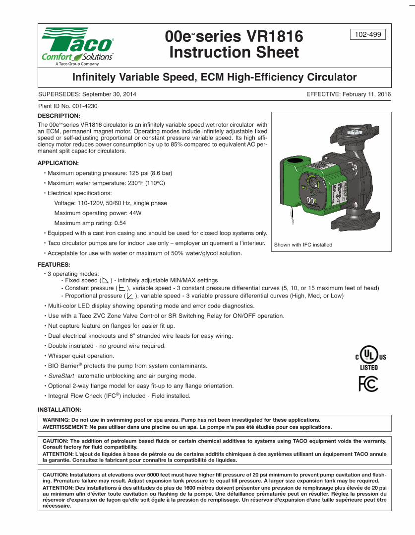
KEY:
VI, V2, V3 = SHUT-OFF ISOLATION VALVE
P = TACO CIRCULATOR WITH IFC
FF = FAST FILL BOILER FEED VALVE
PV4 = PURGE VALVE
RECOMMENDED PURGING STEPS:
1. CLOSE V1, PV4, V2
2. OPEN V3
3. OPEN FF VALVE
4. OPEN V2, PV4, TO PURGE LAST ZONE
FIRST (ZONE 3)
5. CLOSE FF VALVE
6. CLOSE V2, PV4
7. REPEAT STEPS 1 TO 6 FOR EACH
ADDITIONAL ZONE, PURGE ZONE 1 LAST
8. OPEN V1 WHEN ALL ZONES ARE
PURGED
9. ADJUST SYSTEM TO DESIRED OPERATING
FILL PRESSURE IF REQUIRED
BOILER
FF
EXPANSIONTANK
ZONE 1ZONE 2
V1
PV4
FIGURE 1:
MULTI-SPEED MODE
PREFERRED PIPINGFOR CIRCULATORSON BOILER SUPPLY
ZONE 1
V2
V3
P
ZONE 3
ZONE 2
V2
V3
P
ZONE 3
V2
V3
P
• AIR PURGING SEQUENCE BY ZONE
LAST FIRST
BOILER
FF
EXPANSIONTANK
ZONE1
ZONE2
V1
PV4
ALTERNATE PIPINGFOR CIRCULATORSON BOILER RETURN
ZONE 1ZONE 2
V2V2
V3V3
P P
ZONE3ZONE 3
V2
V3
P • AIR PURGING SEQUENCE BY ZONE
LAST FIRST
3
BOILER
FF
EXPANSIONTANK
ZONE 1ZONE 2
V1
PV4
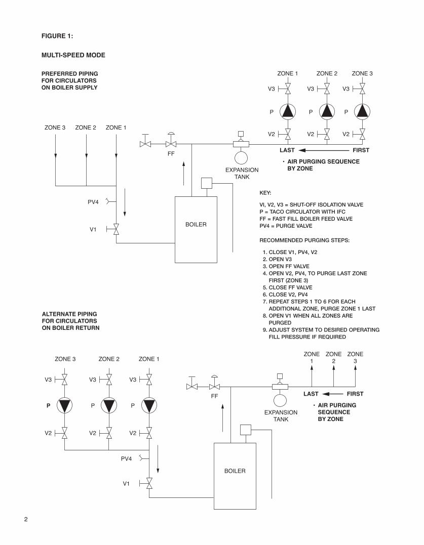
FIGURE 2:
MULTI-SPEED OR VARIABLE SPEED MODES
PREFERRED PIPINGFOR ZONE VALVESON BOILER SUPPLY
ZONE 1
V2
V3
ZONE 3
ZONE 2
V2
V3
ZONE 3
V2
V3
• AIR PURGING SEQUENCE BY ZONE
LAST FIRST
BOILER
FF
EXPANSIONTANK
ZONE1
ZONE2
V1
PV4
ALTERNATE PIPINGFOR ZONE VALVESON BOILER RETURN
ZONE 1ZONE 2
V2V2
V3V3
ZONE3ZONE 3
V2
V3
• AIR PURGING SEQUENCE BY ZONE
LAST FIRST
P
PZV3 ZV2 ZV1M
ZV1 ZV2 ZV3
M M
MMM
KEY:
VI, V2, V3 = SHUT-OFF ISOLATION VALVE
P = TACO CIRCULATOR WITHOUT IFC INSTALLED
FF = FAST FILL BOILER FEED VALVE
PV4 = PURGE VALVE
ZV = ZONE VALVE
RECOMMENDED PURGING STEPS:
1. CLOSE V1, PV4, V2
2. OPEN V3 AND ZV3
3. OPEN FF VALVE
4. OPEN V2, PV4, TO PURGE LAST ZONE
FIRST (ZONE 3)
5. CLOSE FF VALVE
6. CLOSE V2, PV4
7. REPEAT STEPS 1 TO 6 FOR EACH
ADDITIONAL ZONE, PURGE ZONE 1 LAST
8. OPEN V1 WHEN ALL ZONES ARE
PURGED
9. ADJUST SYSTEM TO DESIRED OPERATING
FILL PRESSURE IF REQUIRED
10. MOVE ALL ZV TO CLOSED/AUTOMATIC
POSITION
4
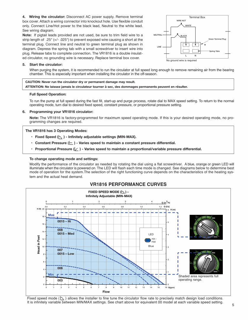
ACCEPTABLE MOTOR MOUNTING POSITIONS CASING ROTATION
To rotate the casing, remove the 4 motor screws and spin the cas-ing to the desired flow direction. Reattach the 4 screws (1⁄8" allenswrench required). Be sure body gasket is seated evenly. Tightenmotor screws to 34-42 in-lbs torque.
WARNING: Use supply wires suitable for 90°C. AVERTISSEMENT: Employer des fils d’alimentation adeqauts pour 90°C.
1. Location:
The circulator can be installed on the supply or return side of the boiler but for best system performance, it should always pumpaway from the expansion tank. See piping diagrams in Figures no.1 and no. 2.
2. Mounting position:
Circulator must be mounted with the motor in the horizontal position. See diagrams below for acceptable motor mounting orientations.
3. Fill the system with tap water or a maximum of 50% propylene-glycol and water solution:The system must be filled before operating the circulator. The bearings are water lubricated and should not be allowed to operatedry. Filling the system will result in immediate lubrication of the bearings. It is always good practice to flush a new system of foreignmatter before starting the circulator.
Position electrical junction box at 9 o’clock position for best programming and viewing orientation. Casing maybe rotated to change flow direction. Locate the arrow on the casing body to determine flow direction.
CAUTION: To reduce the possibility of noise transmission, be sure to add vibration dampeners to piping when mounting circulator to wallor floor joists.
ATTENTION: Pour réduire la possibilité de transmission de bruit, veillez à ajouter des amortisseurs de vibration à la tuyauterie lors dumontage du circulateur sur des chevêtres de mur ou de plancher.
WARNING: Risk of electric shock. To reduce the risk of electric shock, be certain that it is connected only to a properly grounded, ground-ing-type receptacle. Follow all local electrical and plumbing codes.
AVERTISSEMENT: Risque de choc électrique. Pour réduire le risque de choc électrique, veillez à ce qu'elle soit raccordée uniquement àun réceptacle de type mise à la terre proprement mis à la terre. Respectez tous les codes de plomberie et électriques locaux.
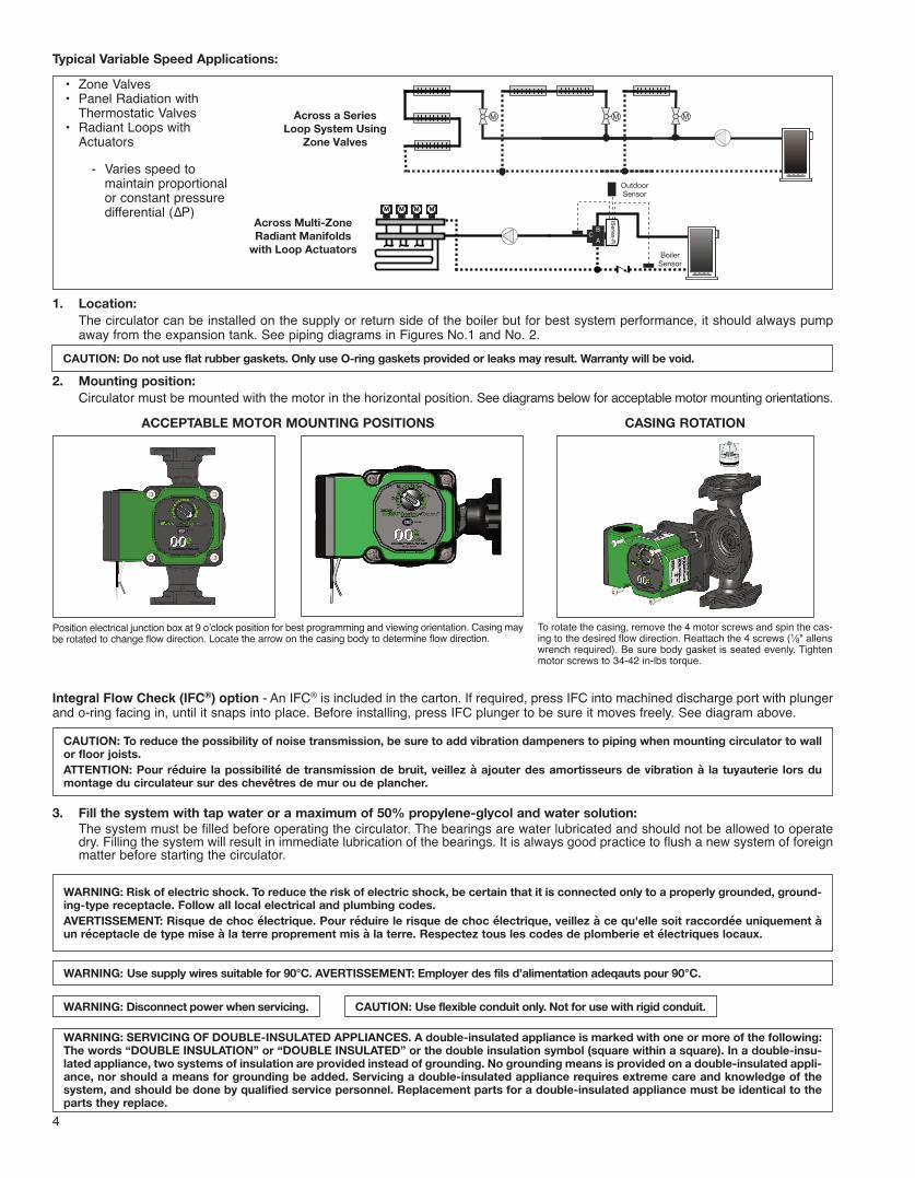
Across a SeriesLoop System Using
Zone Valves
MMM
Across Multi-ZoneRadiant Manifolds
with Loop Actuators
iSeries-R
BCA
BCA
MM MM MM MM
OutdoorSensor
BoilerSensor
Typical Variable Speed Applications:
• Zone Valves• Panel Radiation with
Thermostatic Valves• Radiant Loops with
Actuators
- Varies speed tomaintain proportionalor constant pressuredifferential (∆P)
WARNING: Disconnect power when servicing. CAUTION: Use flexible conduit only. Not for use with rigid conduit.
CAUTION: Do not use flat rubber gaskets. Only use O-ring gaskets provided or leaks may result. Warranty will be void.
WARNING: SERVICING OF DOUBLE-INSULATED APPLIANCES. A double-insulated appliance is marked with one or more of the following:The words “DOUBLE INSULATION” or “DOUBLE INSULATED” or the double insulation symbol (square within a square). In a double-insu-lated appliance, two systems of insulation are provided instead of grounding. No grounding means is provided on a double-insulated appli-ance, nor should a means for grounding be added. Servicing a double-insulated appliance requires extreme care and knowledge of thesystem, and should be done by qualified service personnel. Replacement parts for a double-insulated appliance must be identical to theparts they replace.
Integral Flow Check (IFC®) option - An IFC® is included in the carton. If required, press IFC into machined discharge port with plungerand o-ring facing in, until it snaps into place. Before installing, press IFC plunger to be sure it moves freely. See diagram above.
5
5. Start the circulator:
When purging the system, it is recommended to run the circulator at full speed long enough to remove remaining air from the bearingchamber. This is especially important when installing the circulator in the off-season.
Full Speed Operation:
To run the pump at full speed during the fast fill, start-up and purge process, rotate dial to MAx speed setting. To return to the normaloperating mode, turn dial to desired fixed speed, constant pressure, or proportional pressure setting.
6. Programming your VR1816 circulator:
Note: The VR1816 is factory-programmed for maximum speed operating mode. If this is your desired operating mode, no pro-gramming changes are required.
To change operating mode and settings:
Modify the performance of the circulator as needed by rotating the dial using a flat screwdriver. A blue, orange or green LED willilluminate when the circulator is powered on. The LED will flash each time mode is changed. See diagrams below to determine bestmode of operation for the system.The selection of the right functioning curve depends on the characteristics of the heating sys-tem and the actual heat demand.
CAUTION: Never run the circulator dry or permanent damage may result.
ATTENTION: Ne laissez jamais le circulateur tourner à sec, des dommages permanents peuvent en résulter.
The VR1816 has 3 Operating Modes:
• Fixed Speed ( ) - Infinitely adjustable settings (MIN-MAX).
• Constant Pressure ( ) - Varies speed to maintain a constant pressure differential.
• Proportional Pressure ( ) - Varies speed to maintain a proportional/variable pressure differential.
Min
Max
Q(gpm)0 1 2 3 4 5 6 7 8 9 10 11 12 13 14 15 16
H (ft)
0
2
4
6
8
10
12
14
16
18
20Q (l/s)0.0 0.2 0.4 0.6 0.8 1.0 1.2
H (m)
0
1
2
3
4
5
6
Q (m3/h)43210
0015 – Hi
0080015 – Med
0070015 – Low
006
003
Flow
Head
in F
eet
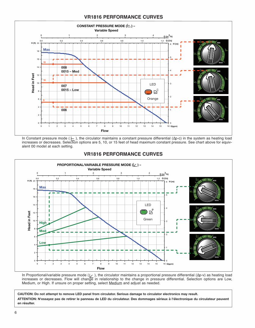
FIXED SPEED MODE ( ) – Infinitely Adjustable (MIN-MAX)
Fixed speed mode ( ) allows the installer to fine tune the circulator flow rate to precisely match design load conditions.It is infinitely variable between MIn/MAx settings. See chart above for equivalent 00 model at each variable speed setting.
Shaded area represents fulloperating range.
Blue
LEDmin -max
4. Wiring the circulator: Disconnect AC power supply. Remove terminal
box cover. Attach a wiring connector into knockout hole. Use flexible conduit
only. Connect Line/Hot power to the black lead, Neutral to the white lead.
See wiring diagram.
Note: If pigtail leads provided are not used, be sure to trim field wire to a
strip length of .25" (+/- .025") to prevent exposed wire causing a short at the
terminal plug. Connect line and neutral to green terminal plug as shown in
diagram. Depress the spring tab with a small screwdriver to insert wire into
plug. Release tabs to complete connection. The VR1816 is a double insulat-
ed circulator, no grounding wire is necessary. Replace terminal box cover.
NEUTRAL
T
L N
Green Terminal Plug
Spring Tabs
WIRE NUT
WHITE
BLACK
LINE
no ground wire is required
Terminal Box
VR1816 PERFORMANCE CURVES
CAUTION: Do not attempt to remove LED panel from circulator. Serious damage to circulator electronics may result.
ATTENTION: N'essayez pas de retirer le panneau de LED du circulateur. Des dommages sérieux à l'électronique du circulateur peuvent
en résulter.
6
5
10
15
Max
Q(gpm)0 1 2 3 4 5 6 7 8 9 10 11 12 13 14 15 16
H (ft)
0
2
4
6
8
10
12
14
16
18
20Q (l/s)0.0 0.2 0.4 0.6 0.8 1.0 1.2
H (m)
0
1
2
3
4
5
6
Q (m3/h)43210
0080015 – Med
0070015 – Low
006
Flow
Head
in F
eet
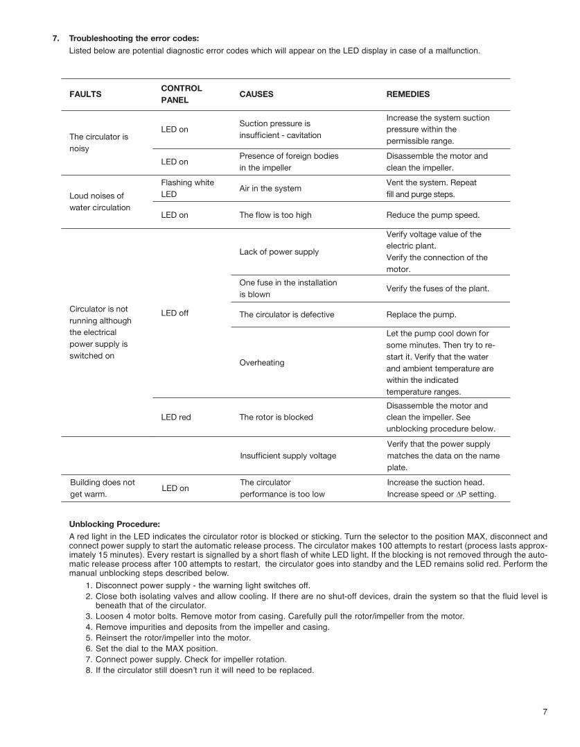
CONSTANT PRESSURE MODE ( ) – Variable Speed
In Constant pressure mode ( ), the circulator maintains a constant pressure differential (∆p-c) in the system as heating loadincreases or decreases. Selection options are 5, 10, or 15 feet of head maximum constant pressure. See chart above for equiv-alent 00 model at each setting.
Low
Med
High
Max
Q(gpm)0 1 2 3 4 5 6 7 8 9 10 11 12 13 14 15 16
H (ft)
0
2
4
6
8
10
12
14
16
18
20Q (l/s)0.0 0.2 0.4 0.6 0.8 1.0 1.2
H (m)
0
1
2
3
4
5
6
Q (m3/h)43210
Flow
Head
in F
eet
PROPORTIONAL/VARIABLE PRESSURE MODE ( ) – Variable Speed
In Proportional/variable pressure mode ( ), the circulator maintains a proportional pressure differential (∆p-v) as heating loadincreases or decreases. Flow will change in relationship to the change in pressure differential. Selection options are Low,Medium, or High. If unsure on proper setting, select Medium and adjust as needed.
Orange
LED
Green
LED
VR1816 PERFORMANCE CURVES
VR1816 PERFORMANCE CURVES
7
7. Troubleshooting the error codes:
Listed below are potential diagnostic error codes which will appear on the LED display in case of a malfunction.
FAULTS CONTROL PANEL CAUSES REMEDIES
The circulator is noisy
LED on Suction pressure is insufficient - cavitation
Increase the system suction pressure within the permissible range.
LED on Presence of foreign bodies in the impeller
Disassemble the motor and clean the impeller.
Loud noises of water circulation
Flashing white LED Air in the system Vent the system. Repeat
fill and purge steps.
LED on The flow is too high Reduce the pump speed.
Circulator is not running although the electrical power supply isswitched on
LED off
Lack of power supply
Verify voltage value of the electric plant.Verify the connection of the motor.
One fuse in the installation is blown Verify the fuses of the plant.
The circulator is defective Replace the pump.
Overheating
Let the pump cool down for some minutes. Then try to re-start it. Verify that the water and ambient temperature are within the indicated temperature ranges.
LED red The rotor is blockedDisassemble the motor and clean the impeller. See unblocking procedure below.
Insufficient supply voltageVerify that the power supply matches the data on the name plate.
Building does not get warm. LED on The circulator
performance is too lowIncrease the suction head. Increase speed or ∆P setting.
Unblocking Procedure:
A red light in the LED indicates the circulator rotor is blocked or sticking. Turn the selector to the position MAx, disconnect andconnect power supply to start the automatic release process. The circulator makes 100 attempts to restart (process lasts approx-imately 15 minutes). Every restart is signalled by a short flash of white LED light. If the blocking is not removed through the auto-matic release process after 100 attempts to restart, the circulator goes into standby and the LED remains solid red. Perform themanual unblocking steps described below.
1. Disconnect power supply - the warning light switches off.2. Close both isolating valves and allow cooling. If there are no shut-off devices, drain the system so that the fluid level is
beneath that of the circulator.3. Loosen 4 motor bolts. Remove motor from casing. Carefully pull the rotor/impeller from the motor.4. Remove impurities and deposits from the impeller and casing.5. Reinsert the rotor/impeller into the motor.6. Set the dial to the MAx position.7. Connect power supply. Check for impeller rotation.8. If the circulator still doesn’t run it will need to be replaced.
LIMITED WARRANTY STATEMENTTaco, Inc. will repair or replace without charge (atthe company’s option) any Taco High Efficiencycirculator or circulator part which is proven defec-tive under normal use within three (3) years fromthe date of manufacture.In order to obtain service under this warranty, itis the responsibility of the purchaser to promptlynotify the local Taco stocking distributor or Tacoin writing and promptly deliver the subject productor part, delivery prepaid, to the stocking distribu-tor. For assistance on warranty returns, the pur-chaser may either contact the local Taco stock-ing distributor or Taco. If the subject product orpart contains no defect as covered in this war-ranty, the purchaser will be billed for parts andlabor charges in effect at time of factory exami-nation and repair.Any Taco product or part not installed or operatedin conformity with Taco instructions or which hasbeen subject to misuse, misapplication, the addi-tion of petroleum-based fluids or certain chemi-cal additives to the systems, or other abuse, willnot be covered by this warranty.
If in doubt as to whether a particular substanceis suitable for use with a Taco product or part, orfor any application restrictions, consult theapplicable Taco instruction sheets or contactTaco at (401-942-8000).Taco reserves the right to provide replacementproducts and parts which are substantially similarin design and functionally equivalent to thedefective product or part. Taco reserves the rightto make changes in details of design, construc-tion, or arrangement of materials of its productswithout notification.TACO OFFERS THIS WARRANTY IN LIEU OF
ALL OTHER EXPRESS WARRANTIES. ANY
WARRANTY IMPLIED BY LAW INCLUDING
WARRANTIES OF MERCHANTABILITY OR
FITNESS IS IN EFFECT ONLY FOR THE DURA-
TION OF THE EXPRESS WARRANTY SET
FORTH IN THE FIRST PARAGRAPH ABOVE.
THE ABOVE WARRANTIES ARE IN LIEU OF
ALL OTHER WARRANTIES, EXPRESS OR
STATUTORY, OR ANY OTHER WARRANTY
OBLIGATION ON THE PART OF TACO.
TACO WILL NOT BE LIABLE FOR ANY SPE-
CIAL, INCIDENTAL, INDIRECT OR CONSE-
QUENTIAL DAMAGES RESULTING FROM THE
USE OF ITS PRODUCTS OR ANY INCIDENTAL
COSTS OF REMOVING OR REPLACING
DEFECTIVE PRODUCTS.
This warranty gives the purchaser specific rights,and the purchaser may have other rights whichvary from state to state. Some states do notallow limitations on how long an implied warrantylasts or on the exclusion of incidental or conse-quential damages, so these limitations or exclu-sions may not apply to you.
8
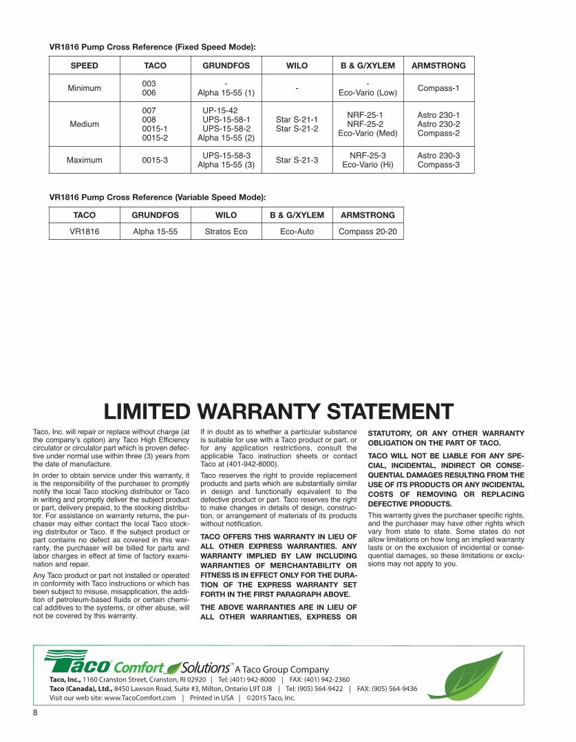
SPEED TACO GRUNDFOS WILO B & G/XYLEM ARMSTRONG
Minimum 003006
-Alpha 15-55 (1) - -
Eco-Vario (Low) Compass-1
Medium0070080015-10015-2
UP-15-42UPS-15-58-1UPS-15-58-2
Alpha 15-55 (2)
Star S-21-1Star S-21-2
nRF-25-1nRF-25-2
Eco-Vario (Med)
Astro 230-1Astro 230-2Compass-2
Maximum 0015-3 UPS-15-58-3Alpha 15-55 (3) Star S-21-3 nRF-25-3
Eco-Vario (Hi)Astro 230-3Compass-3
VR1816 Pump Cross Reference (Fixed Speed Mode):
TACO GRUNDFOS WILO B & G/XYLEM ARMSTRONG
VR1816 Alpha 15-55 Stratos Eco Eco-Auto Compass 20-20
VR1816 Pump Cross Reference (Variable Speed Mode):