Embed Size (px)
Citation preview
M S E R I E S
INSTALLATION, COMMISSIONING, AND MAINTENANCE MANUAL
Serial Number _______________________________________________ Date of Installation ____________Date of Commissioning ___________
UNITED Fire Systems Division of UNITED Fire Protection Corporation
1 Mark Road Kenilworth, NJ USA 07033 Manual Part Number 30-NPMICM-000 908-688-0300 Revision 1.00 www.unitedfiresystems.net February 2015

UNITED FIRE SYSTEMS NITROGEN-PAC™ M SERIES
INSTALLATION, COMMISSIONING, AND MAINTENANCE MANUAL REVISION 1.00 – FEB 2015
P/N 30-NPMICM-000
i
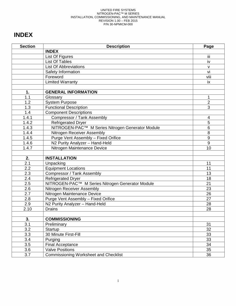
INDEX
Section Description Page INDEX List Of Figures iii List Of Tables iv List Of Abbreviations v Safety Information vi Foreword viii Limited Warranty ix
1. GENERAL INFORMATION 1.1 Glossary 1 1.2 System Purpose 2 1.3 Functional Description 3 1.4 Component Descriptions
1.4.1 Compressor / Tank Assembly 4 1.4.2 Refrigerated Dryer 5 1.4.3 NITROGEN-PAC™ M Series Nitrogen Generator Module 6 1.4.4 Nitrogen Receiver Assembly 8 1.4.5 Purge Vent Assembly – Fixed Orifice 9 1.4.6 N2 Purity Analyzer – Hand-Held 9 1.4.7 Nitrogen Maintenance Device 10
2. INSTALLATION
2.1 Unpacking 11 2.2 Equipment Locations 11 2.3 Compressor / Tank Assembly 13 2.4 Refrigerated Dryer 18 2.5 NITROGEN-PAC™ M Series Nitrogen Generator Module 21 2.6 Nitrogen Receiver Assembly 23 2.7 Nitrogen Maintenance Device 26 2.8 Purge Vent Assembly – Fixed Orifice 27 2.9 N2 Purity Analyzer – Hand-Held 28 2.10 Drains 28
3. COMMISSIONING
3.1 Preliminary 31 3.2 Startup 32 3.3 30 Minute First-Fill 33 3.4 Purging 33 3.5 Final Acceptance 34 3.6 Valve Positions 35 3.7 Commissioning Worksheet and Checklist 36
UNITED FIRE SYSTEMS NITROGEN-PAC™ M SERIES
INSTALLATION, COMMISSIONING, AND MAINTENANCE MANUAL REVISION 1.00 – FEB 2015
P/N 30-NPMICM-000
ii
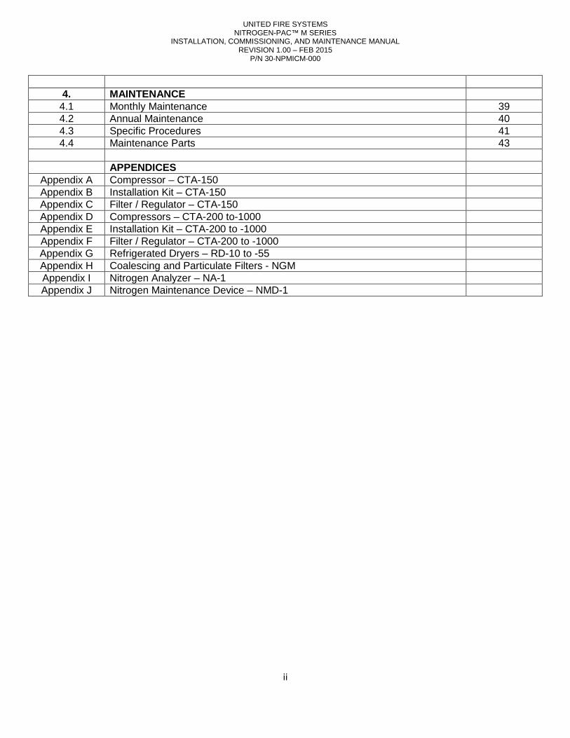
4. MAINTENANCE
4.1 Monthly Maintenance 39 4.2 Annual Maintenance 40 4.3 Specific Procedures 41 4.4 Maintenance Parts 43
APPENDICES
Appendix A Compressor – CTA-150 Appendix B Installation Kit – CTA-150 Appendix C Filter / Regulator – CTA-150 Appendix D Compressors – CTA-200 to-1000 Appendix E Installation Kit – CTA-200 to -1000 Appendix F Filter / Regulator – CTA-200 to -1000 Appendix G Refrigerated Dryers – RD-10 to -55 Appendix H Coalescing and Particulate Filters - NGM Appendix I Nitrogen Analyzer – NA-1 Appendix J Nitrogen Maintenance Device – NMD-1
UNITED FIRE SYSTEMS NITROGEN-PAC™ M SERIES
INSTALLATION, COMMISSIONING, AND MAINTENANCE MANUAL REVISION 1.00 – FEB 2015
P/N 30-NPMICM-000
iii
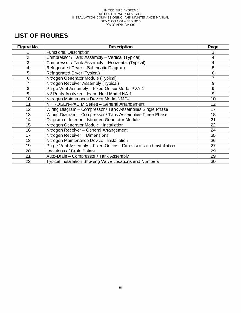
LIST OF FIGURES
Figure No. Description Page 1 Functional Description 3 2 Compressor / Tank Assembly – Vertical (Typical) 4 3 Compressor / Tank Assembly – Horizontal (Typical) 4 4 Refrigerated Dryer – Schematic Diagram 5 5 Refrigerated Dryer (Typical) 6 6 Nitrogen Generator Module (Typical) 7 7 Nitrogen Receiver Assembly (Typical) 8 8 Purge Vent Assembly – Fixed Orifice Model PVA-1 9 9 N2 Purity Analyzer – Hand-Held Model NA-1 9 10 Nitrogen Maintenance Device Model NMD-1 10 11 NITROGEN-PAC M Series – General Arrangement 12 12 Wiring Diagram – Compressor / Tank Assemblies Single Phase 17 13 Wiring Diagram – Compressor / Tank Assemblies Three Phase 18 14 Diagram of Interior – Nitrogen Generator Module 21 15 Nitrogen Generator Module - Installation 22 16 Nitrogen Receiver – General Arrangement 24 17 Nitrogen Receiver – Dimensions 25 18 Nitrogen Maintenance Device - Installation 26 19 Purge Vent Assembly – Fixed Orifice – Dimensions and Installation 27 20 Locations of Drain Points 29 21 Auto-Drain – Compressor / Tank Assembly 29 22 Typical Installation Showing Valve Locations and Numbers 30
UNITED FIRE SYSTEMS NITROGEN-PAC™ M SERIES
INSTALLATION, COMMISSIONING, AND MAINTENANCE MANUAL REVISION 1.00 – FEB 2015
P/N 30-NPMICM-000
iv
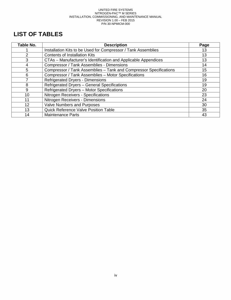
LIST OF TABLES
Table No. Description Page 1 Installation Kits to be Used for Compressor / Tank Assemblies 13 2 Contents of Installation Kits 13 3 CTAs – Manufacturer’s Identification and Applicable Appendices 13 4 Compressor / Tank Assemblies - Dimensions 14 5 Compressor / Tank Assemblies – Tank and Compressor Specifications 15 6 Compressor / Tank Assemblies – Motor Specifications 16 7 Refrigerated Dryers - Dimensions 19 8 Refrigerated Dryers – General Specifications 19 9 Refrigerated Dryers – Motor Specifications 20 10 Nitrogen Receivers - Specifications 23 11 Nitrogen Receivers - Dimensions 24 12 Valve Numbers and Purposes 30 13 Quick Reference Valve Position Table 35 14 Maintenance Parts 43
UNITED FIRE SYSTEMS NITROGEN-PAC™ M SERIES
INSTALLATION, COMMISSIONING, AND MAINTENANCE MANUAL REVISION 1.00 – FEB 2015
P/N 30-NPMICM-000
v
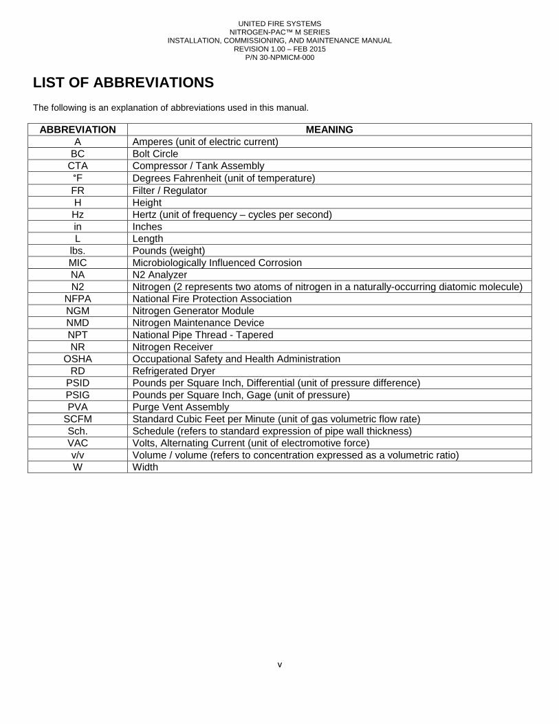
LIST OF ABBREVIATIONS The following is an explanation of abbreviations used in this manual.
ABBREVIATION MEANING A Amperes (unit of electric current)
BC Bolt Circle CTA Compressor / Tank Assembly
°F Degrees Fahrenheit (unit of temperature) FR Filter / Regulator H Height Hz Hertz (unit of frequency – cycles per second) in Inches L Length
lbs. Pounds (weight) MIC Microbiologically Influenced Corrosion NA N2 Analyzer N2 Nitrogen (2 represents two atoms of nitrogen in a naturally-occurring diatomic molecule)
NFPA National Fire Protection Association NGM Nitrogen Generator Module NMD Nitrogen Maintenance Device NPT National Pipe Thread - Tapered NR Nitrogen Receiver
OSHA Occupational Safety and Health Administration RD Refrigerated Dryer
PSID Pounds per Square Inch, Differential (unit of pressure difference) PSIG Pounds per Square Inch, Gage (unit of pressure) PVA Purge Vent Assembly
SCFM Standard Cubic Feet per Minute (unit of gas volumetric flow rate) Sch. Schedule (refers to standard expression of pipe wall thickness) VAC Volts, Alternating Current (unit of electromotive force) v/v Volume / volume (refers to concentration expressed as a volumetric ratio) W Width
INSTALLATION, COMMISSIONING, AND MAINTENANCE MANUAL
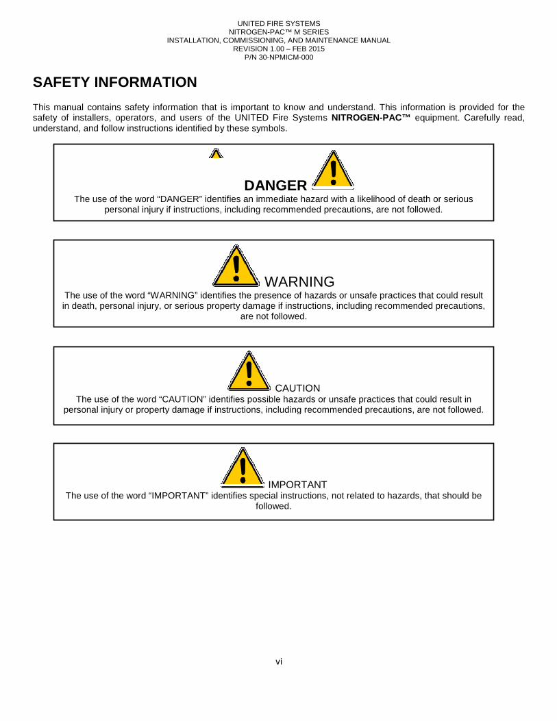
SAFETY INFORMATION This manual contains safety information that is important to know and understand. This information is provided for the safety of installers, operators, and users of the understand, and follow instructions identified by these symbols.
The use of the word “DANGER” identifies an immediate hazard with a likelihood of death or serious personal injury if instructions, including recommended precautions, are not followed.
The use of the word “WARNING” identifies the presence of hazards or unsafe practices that could result in death, personal injury, or serious property damage if instructions, including recommended precautions,
The use of the word “CAUTION” identifies possible hazards or unsafe practices that could result in personal injury or property damage if instructions, including recommended precautions, are not followed.
The use of the word “IMPORTANT” identifies special instructions, not related to hazards, that should be
UNITED FIRE SYSTEMS NITROGEN-PAC™ M SERIES
INSTALLATION, COMMISSIONING, AND MAINTENANCE MANUAL REVISION 1.00 – FEB 2015
P/N 30-NPMICM-000
vi
This manual contains safety information that is important to know and understand. This information is provided for the safety of installers, operators, and users of the UNITED Fire Systems NITROGEN-PAC™ equipment.
tructions identified by these symbols.
DANGER The use of the word “DANGER” identifies an immediate hazard with a likelihood of death or serious
personal injury if instructions, including recommended precautions, are not followed.
WARNING The use of the word “WARNING” identifies the presence of hazards or unsafe practices that could result in death, personal injury, or serious property damage if instructions, including recommended precautions,
are not followed.
CAUTION The use of the word “CAUTION” identifies possible hazards or unsafe practices that could result in
personal injury or property damage if instructions, including recommended precautions, are not followed.
IMPORTANT T” identifies special instructions, not related to hazards, that should be
followed.
This manual contains safety information that is important to know and understand. This information is provided for the equipment. Carefully read,
The use of the word “DANGER” identifies an immediate hazard with a likelihood of death or serious personal injury if instructions, including recommended precautions, are not followed.
The use of the word “WARNING” identifies the presence of hazards or unsafe practices that could result in death, personal injury, or serious property damage if instructions, including recommended precautions,
The use of the word “CAUTION” identifies possible hazards or unsafe practices that could result in personal injury or property damage if instructions, including recommended precautions, are not followed.
T” identifies special instructions, not related to hazards, that should be
INSTALLATION, COMMISSIONING, AND MAINTENANCE MANUAL
IMPORTANT NOTICES TO INSTALLERS AND USERS This manual must be read thoroughly and completely understood before installation and operation of Systems NITROGEN-PAC™ equipment. All appropriate safety standards for handling of gases as determined by local or national laws and regulations should be followed at all times.
General Safety Information
When handling, installing, or operating this equipment, personnel must employ safe engineering practices and observe all related local regulations, health, and safety procedures, and legal requirements for Ensure that the equipment is depressurized and electrically isolated before carrying out any of the scheduled maintenance instructions specified in this manual. Nitrogen is not a poisonous gas. However, in a concentrated form, there is a risk of Module produces both a flow of nitrogen and However, do not directly inhale the output gas from the outlet pipe. The Nitrogen Generator Module is classified as nonregulations. This equipment is for indoor use only. Do not operate outdoors.
Specific procedures must be followed for maintenance of themodule is connected. Appropriate labels must be continuously displayed in all areas where personnel mto a nitrogen atmosphere.
Do not connect Nitrogen Generator ModuleFailure to do so could cause rupture, leading to death, personal injury, or serious property damage.
Read all of the safety information in this manual before operating this equipment. Use of the equipment in a manner not specified within this manual may impair the protection provided by the equipment and could result in an unplanned release of pressure, which may cause serious injury or damage
competent personnel, who have been trained, qualified, and approved by commissioning, servicing, and repair procedures.
Do not operate unit if damage occurred during shipping, hanFailure to do so could result in death, personal injury, or serious property damage.
UNITED FIRE SYSTEMS NITROGEN-PAC™ M SERIES
INSTALLATION, COMMISSIONING, AND MAINTENANCE MANUAL REVISION 1.00 – FEB 2015
P/N 30-NPMICM-000
vii
IMPORTANT NOTICES TO INSTALLERS AND USERS
manual must be read thoroughly and completely understood before installation and operation of equipment. All appropriate safety standards for handling of gases as determined by local or
national laws and regulations should be followed at all times.
When handling, installing, or operating this equipment, personnel must employ safe engineering practices and observe all related local regulations, health, and safety procedures, and legal requirements for safety.
Ensure that the equipment is depressurized and electrically isolated before carrying out any of the scheduled maintenance instructions specified in this manual.
Nitrogen is not a poisonous gas. However, in a concentrated form, there is a risk of asphyxiation. The a flow of nitrogen and a flow of oxygen enriched air which quickly disperses in the atmosphere.
However, do not directly inhale the output gas from the outlet pipe.
is classified as non-hazardous for transportation purposes and as nonregulations. This equipment is for indoor use only. Do not operate outdoors.
for maintenance of the Nitrogen Generator Module and theAppropriate labels must be continuously displayed in all areas where personnel m
WARNING Module to compressed air sources that can exceed its maximum rated pressure.
Failure to do so could cause rupture, leading to death, personal injury, or serious property damage.
IMPORTANT ead all of the safety information in this manual before operating this equipment. Use of the equipment in a manner
not specified within this manual may impair the protection provided by the UNITED Fire Systemsunplanned release of pressure, which may cause serious injury or damage
competent personnel, who have been trained, qualified, and approved by UNITED Fire Systems should perform commissioning, servicing, and repair procedures.
WARNING Do not operate unit if damage occurred during shipping, handling, or use. Contact UNITED Fire Systems immediately.
Failure to do so could result in death, personal injury, or serious property damage.
manual must be read thoroughly and completely understood before installation and operation of UNITED Fire equipment. All appropriate safety standards for handling of gases as determined by local or
When handling, installing, or operating this equipment, personnel must employ safe engineering practices and observe all
Ensure that the equipment is depressurized and electrically isolated before carrying out any of the scheduled
asphyxiation. The Nitrogen Generator oxygen enriched air which quickly disperses in the atmosphere.
hazardous for transportation purposes and as non-flammable for fire
Nitrogen Generator Module and the equipment to which the Appropriate labels must be continuously displayed in all areas where personnel might be exposed
exceed its maximum rated pressure. Failure to do so could cause rupture, leading to death, personal injury, or serious property damage.
ead all of the safety information in this manual before operating this equipment. Use of the equipment in a manner Fire Systems NITROGEN-PAC™
unplanned release of pressure, which may cause serious injury or damage. Only Fire Systems should perform
Fire Systems immediately. Failure to do so could result in death, personal injury, or serious property damage.
INSTALLATION, COMMISSIONING, AND MAINTENANCE MANUAL
FOREWORD
This manual is written for those who install, operate and maintain corrosion inhibiting systems. The manual contains installation, operation, and maintenanceassemblies.
UNITED Fire Systems NITROGEN-PAC™ qualified, trained personnel in accordance with:
• This Installation, Operation, and Main• National Fire Protection Association No. 13, “Standard for the Installation of Sprinkler Systems.”• National Fire Protection Association No. 25,
Water-Based Fire Protection Systems• National Fire Protection Association No. 70, “National Electrical Code®”.
Any questions on the information in this manual should be
Division of
UNITED Fire Systems assumes no responsibility for the installation, operation, or maintenance of any systems other than those addressed in this manual. The data contained in this manual is for information purposes only. UNITEDFire Systems believes this data to be accurate
without any guarantee or warranty whatsoever. UNITEDmade of the data and information contained in this manual by any and all
The UNITED Fire Systems NITROGEN-PAC™of any facility where these units are installed. Life safety and property protection depends on cont
operation of the assembly. The owner of the its continued proper operation. UNITED Fire Systemssystems engage the services of qualified, trained fire protection professionals to design the system containing the
assembly, and to install and maintain the assembly.
UNITED FIRE SYSTEMS NITROGEN-PAC™ M SERIES
INSTALLATION, COMMISSIONING, AND MAINTENANCE MANUAL REVISION 1.00 – FEB 2015
P/N 30-NPMICM-000
viii
This manual is written for those who install, operate and maintain UNITED Fire Systems NITROGEN
. The manual contains installation, operation, and maintenance
sprinkler corrosion inhibiting systems are to be installed
qualified, trained personnel in accordance with:
This Installation, Operation, and Maintenance Manual P/N 30-NPMIOM-000. National Fire Protection Association No. 13, “Standard for the Installation of Sprinkler Systems.”
tection Association No. 25, “Standard for the Inspection, Testing, and Maintenance of Based Fire Protection Systems.”
National Fire Protection Association No. 70, “National Electrical Code®”.
Any questions on the information in this manual should be addressed to:
UNITED Fire Systems Division of United Fire Protection Corporation
1 Mark Road Kenilworth, NJ USA 07033
908-688-0300 www.unitedfiresystems.net
IMPORTANT assumes no responsibility for the installation, operation, or maintenance of any systems other
than those addressed in this manual. The data contained in this manual is for information purposes only. UNITEDbelieves this data to be accurate at the time of publication, but the data is published and presented
without any guarantee or warranty whatsoever. UNITED Fire Systems disclaims any liability for any use that may be made of the data and information contained in this manual by any and all parties.
IMPORTANT PAC™ sprinkler corrosion inhibiting system is a vital part of the fire protection
of any facility where these units are installed. Life safety and property protection depends on contoperation of the assembly. The owner of the NITROGEN-PAC™ is responsible for the condition of the assembly and
Fire Systems strongly recommends that all owners of ces of qualified, trained fire protection professionals to design the system containing the
assembly, and to install and maintain the assembly.
NITROGEN-PAC™ sprinkler . The manual contains installation, operation, and maintenance information for these
are to be installed and maintained by
National Fire Protection Association No. 13, “Standard for the Installation of Sprinkler Systems.” “Standard for the Inspection, Testing, and Maintenance of
assumes no responsibility for the installation, operation, or maintenance of any systems other than those addressed in this manual. The data contained in this manual is for information purposes only. UNITED
at the time of publication, but the data is published and presented disclaims any liability for any use that may be
parties.
sprinkler corrosion inhibiting system is a vital part of the fire protection of any facility where these units are installed. Life safety and property protection depends on continuing proper
is responsible for the condition of the assembly and strongly recommends that all owners of NITROGEN-PAC™
ces of qualified, trained fire protection professionals to design the system containing the
UNITED FIRE SYSTEMS NITROGEN-PAC™ M SERIES
INSTALLATION, COMMISSIONING, AND MAINTENANCE MANUAL REVISION 1.00 – FEB 2015
P/N 30-NPMICM-000
ix
LIMITED WARRANTY NITROGEN-PAC™
What Does This Warranty Cover? This warranty covers all manufacturing defects in material and workmanship in all equipment supplied for new NITROGEN-PAC™ sprinkler corrosion inhibiting systems. How Long Does The Coverage Last? This warranty lasts for eighteen (18) months from the date of shipment to the original purchaser. What Will UNITED Fire Systems Do? UNITED Fire Systems will repair, replace, or refund the purchase price of, at its option, any defective NITROGEN-PAC™ equipment at no charge. What Does This Warranty Not Cover? Equipment that is not properly installed and maintained per UNITED Fire Systems manual P/N 30-NPMIOM-000 is not covered. Equipment that has been repaired or tampered with not in accordance with the instructions in manual P/N 30-NPMIOM-000 is not covered. This warranty does not cover ordinary maintenance in accordance with manual P/N 30-NPMIOM-000. Transportation and shipping charges to return product to UNITED Fire Systems or for UNITED Fire Systems to ship repaired or replacement product are not covered. Also, consequential and incidental damages are not recoverable under this warranty. Some states do not allow the exclusion or limitation of incidental or consequential damages, so the above limitation or exclusion may not apply. How Do You Obtain Service? In order to eligible for service under this warranty, you must return the warranty registration form within 5 days of installation. If something goes wrong with your NITROGEN-PAC™, contact:
UNITED Fire Systems
Division of UNITED Fire Protection Corporation 1 Mark Road
Kenilworth, NJ USA 07033 908-688-0300
www.unitedfiresystems.net Is This The Entire Warranty? This limited warranty is the entire warranty given by UNITED Fire Systems to the purchaser of NITROGEN-PAC™ equipment. There are no other warranties expressed or implied, beyond those required by law. How Do State and Federal Laws Apply? This warranty gives you specific legal rights per Federal law. You may also have other rights which vary from state to state.
UNITED FIRE SYSTEMS NITROGEN-PAC™ M SERIES
INSTALLATION, COMMISSIONING, AND MAINTENANCE MANUAL REVISION 1.00 – FEB 2015
P/N 30-NPMICM-000
1
1. GENERAL INFORMATION
1.1. GLOSSARY. All glossary terms are defined in reference to their use in this manual. Refer to this glossary for definitions of unfamiliar terms encountered when reading and using this manual.
1.1.1. Air. Air is the naturally occurring gas making up Earth’s atmosphere. Air consists of a mixture of gases, of which
two predominate (see the glossary terms Nitrogen and Oxygen).
1.1.2. Coalescing Filter. The coalescing filter used in NITROGEN-PAC™ systems is located in the Nitrogen Generator Module. This filter separates oil from the dried compressed air, avoiding contamination of the separator membrane.
1.1.3. Compressed Air. Compressed air refers to the output of the NITROGEN-PAC™ Compressor / Tank Assembly.
This air has NOT been conditioned for entry into the Nitrogen Generator Module. The compressed air requires drying by the Refrigerated Dryer before entering the Nitrogen Generator Module.
1.1.4. Pressure Dew Point. The temperature at which the water vapor in a compressed gas at given pressure condenses into liquid water at the same rate at which it evaporates. At temperatures below the pressure dew point, liquid water will leave the gas. At temperatures above the pressure dew point, liquid water will be taken up by the gas.
1.1.5. Dried Compressed Air. Dried compressed air refers to the output of the NITROGEN-PAC™ Refrigerated Dryer. This compressed air has been conditioned for entry into the Nitrogen Generator Module.
1.1.6. Microbiologically Influenced Corrosion (MIC). Microbiologically influenced corrosion (also known as MIC) occurs inside steel dry and preaction sprinkler pipes in the presence of certain microbes. This form of corrosion causes thinning of pipe walls, possibly leading to failure under water pressure. Pinhole leaks can occur, leading to water damage. Roughening of the internal pipe surface leads to unpredictable hydraulics, impairing the effectiveness of the sprinkler system. The tubercles formed by the microbes can loosen, clogging sprinkler heads and impairing or preventing the discharge of water onto a fire. MIC microbes can be aerobic, growing in the presence of oxygen, or anaerobic, not needing oxygen but growing in the presence of water. Prevention of MIC results in longer life and better functionality of the sprinkler system. MIC can be inhibited by using nitrogen to displace oxygen and dry out the inside of the pipe.
1.1.7. Nitrogen (N 2). Nitrogen is a naturally occurring diatomic gas present in Earth’s atmosphere at a concentration of approximately 78% (v/v). All references to “nitrogen” in this manual are the output from the nitrogen outlet of the Nitrogen Generator Module. This outlet delivers gas that is at least 98 percent (v/v) nitrogen, at a pressure dew point of approximately -40°F. The pressure dew point of nitrogen is much lower than of compressed air, making nitrogen much more effective at drying out the inside of a sprinkler pipe.
1.1.8. Oxidation Corrosion. Oxidation corrosion (also known as rust) occurs inside steel dry and preaction sprinkler pipes in the presence of oxygen and water. This form of corrosion causes thinning of pipe walls, possibly leading to failure under water pressure. Pinhole leaks can occur, leading to water damage. Roughening of the internal pipe surface leads to unpredictable hydraulics, impairing the effectiveness of the sprinkler system. Loose rust particles can clog sprinkler heads, impairing or preventing the discharge of water onto a fire. Prevention of oxidation corrosion results in longer life and better functionality of the sprinkler system. Oxidation corrosion can be inhibited by using nitrogen to displace oxygen and dry out the inside of the pipe.
1.1.9. Oxygen (O 2). Oxygen is a naturally occurring diatomic gas present in Earth’s atmosphere at a concentration of
approximately 21% (v/v). Oxygen is discharged from the Nitrogen Generator Module after being separated from dried compressed air by the separator membrane.
1.1.10. Particulate Filter. The particulate filter used in NITROGEN-PAC™ systems is located in the Nitrogen Generator Module. This filter separates particulate matter from the dried compressed air stream, avoiding contamination of the separator membrane.
INSTALLATION,
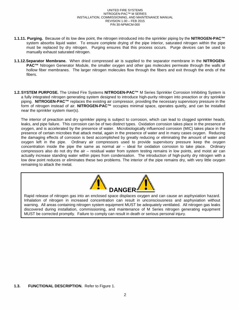
1.1.11. Purging. Because of its low dew point, the
system absorbs liquid water. To ensuremust be replaced by dry nitrogen. Purging ensures that this process occurs. Purge devices canmanually exhaust saturated nitrogen.
1.1.12.Separator Membrane. When dried compressed air is supplied to the separator membrane in the
PAC™ Nitrogen Generator Module, the smaller oxygen and other gas molecules permeate through the walls of hollow fiber membranes. The larger nitrogen molecules flow through the fibers and exit through the ends of the fibers.
1.2. SYSTEM PURPOSE. The United Fire Systemsa fully integrated nitrogen generating system designed to introduce highpiping. NITROGEN-PAC™ replaces the existing air compressor, providing the necessary supervisory pressure in the form of nitrogen instead of air. NITROGENnear the sprinkler system riser(s).
The interior of preaction and dry sprinkler piping is subject to corrosion, which can lead to clogged sprinkler heads, leaks, and pipe failure. This corrosion can be of two distinct types.oxygen, and is accelerated by the presence of water. presence of certain microbes that attack metal, again in the presence of water and in many cases oxygen.the damaging effects of corrosion is best accomplished oxygen left in the pipe. Ordinary air compressors used to provide supervisory pressure keep the oxygen concentration inside the pipe the same as normal air compressors also do not dry the air – actually increase standing water within pipes from condensation.low dew point reduces or eliminates these two problems. The interior of the pipe remains dry, with very little oxygen remaining to attack the metal.
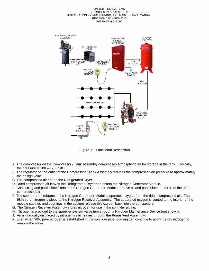
1.3. FUNCTIONAL DESCRIPTION. Refer to
Rapid release of nitrogen gas into an enclosed space displaces oxygen and can cause an asphyxiationInhalation of nitrogen in increased concentration can result in unconsciousness and asphyxiation without warning. All areas containing nitrogen system equipment MUST be adequately ventilated. All nitrogen gas leaks discovered during installation, commissioning, and maintenance of M Series nitrogen generating equipment MUST be corrected promptly. Failure to comply can result in death or serious personal injury.
UNITED FIRE SYSTEMS NITROGEN-PAC™ M SERIES
INSTALLATION, COMMISSIONING, AND MAINTENANCE MANUAL REVISION 1.00 – FEB 2015
P/N 30-NPMICM-000
2
Because of its low dew point, the nitrogen introduced into the sprinkler piping by the system absorbs liquid water. To ensure complete drying of the pipe interior, saturated nitrogen within the pipe must be replaced by dry nitrogen. Purging ensures that this process occurs. Purge devices can
.
When dried compressed air is supplied to the separator membrane in the Nitrogen Generator Module, the smaller oxygen and other gas molecules permeate through the walls of
hollow fiber membranes. The larger nitrogen molecules flow through the fibers and exit through the ends of the
Systems NITROGEN-PAC™ M Series Sprinkler Corrosion Inhibiting System a fully integrated nitrogen generating system designed to introduce high-purity nitrogen into preaction or dry sprinkler
replaces the existing air compressor, providing the necessary supervisory pressure in the NITROGEN-PAC™ occupies minimal space, operates quietly, and can be installed
eaction and dry sprinkler piping is subject to corrosion, which can lead to clogged sprinkler heads, This corrosion can be of two distinct types. Oxidation corrosion takes place in the presence of
e presence of water. Microbiologically influenced corrosion (MIC) takes place in the presence of certain microbes that attack metal, again in the presence of water and in many cases oxygen.the damaging effects of corrosion is best accomplished by greatly reducing or eliminating the amount of water and
Ordinary air compressors used to provide supervisory pressure keep the oxygen concentration inside the pipe the same as normal air – ideal for oxidation corrosion to take
residual water from system testing remains in low points, and moist air can actually increase standing water within pipes from condensation. The introduction of high
point reduces or eliminates these two problems. The interior of the pipe remains dry, with very little oxygen
Refer to Figure 1.
DANGER Rapid release of nitrogen gas into an enclosed space displaces oxygen and can cause an asphyxiationInhalation of nitrogen in increased concentration can result in unconsciousness and asphyxiation without warning. All areas containing nitrogen system equipment MUST be adequately ventilated. All nitrogen gas leaks
n, commissioning, and maintenance of M Series nitrogen generating equipment MUST be corrected promptly. Failure to comply can result in death or serious personal injury.
nitrogen introduced into the sprinkler piping by the NITROGEN-PAC™ drying of the pipe interior, saturated nitrogen within the pipe
must be replaced by dry nitrogen. Purging ensures that this process occurs. Purge devices can be used to
When dried compressed air is supplied to the separator membrane in the NITROGEN-Nitrogen Generator Module, the smaller oxygen and other gas molecules permeate through the walls of
hollow fiber membranes. The larger nitrogen molecules flow through the fibers and exit through the ends of the
M Series Sprinkler Corrosion Inhibiting System is purity nitrogen into preaction or dry sprinkler
replaces the existing air compressor, providing the necessary supervisory pressure in the occupies minimal space, operates quietly, and can be installed
eaction and dry sprinkler piping is subject to corrosion, which can lead to clogged sprinkler heads, Oxidation corrosion takes place in the presence of
corrosion (MIC) takes place in the presence of certain microbes that attack metal, again in the presence of water and in many cases oxygen. Reducing
by greatly reducing or eliminating the amount of water and Ordinary air compressors used to provide supervisory pressure keep the oxygen
ideal for oxidation corrosion to take place. Ordinary system testing remains in low points, and moist air can
The introduction of high-purity dry nitrogen with a point reduces or eliminates these two problems. The interior of the pipe remains dry, with very little oxygen
Rapid release of nitrogen gas into an enclosed space displaces oxygen and can cause an asphyxiation hazard. Inhalation of nitrogen in increased concentration can result in unconsciousness and asphyxiation without warning. All areas containing nitrogen system equipment MUST be adequately ventilated. All nitrogen gas leaks
n, commissioning, and maintenance of M Series nitrogen generating equipment MUST be corrected promptly. Failure to comply can result in death or serious personal injury.
UNITED FIRE SYSTEMS NITROGEN-PAC™ M SERIES
INSTALLATION, COMMISSIONING, AND MAINTENANCE MANUAL REVISION 1.00 – FEB 2015
P/N 30-NPMICM-000
3
A. The compressor on the Compressor / Tank Assembly compresses atmospheric air for storage in the tank. Typically, the pressure is 100 – 175 PSIG.
B. The regulator on the outlet of the Compressor / Tank Assembly reduces the compressed air pressure to approximately the design value.
C. The compressed air enters the Refrigerated Dryer. D. Dried compressed air leaves the Refrigerated Dryer and enters the Nitrogen Generator Module. E. Coalescing and particulate filters in the Nitrogen Generator Module remove oil and particulate matter from the dried
compressed air. F. The separator membrane in the Nitrogen Generator Module separates oxygen from the dried compressed air. The
98% pure nitrogen is piped to the Nitrogen Receiver Assembly. The separated oxygen is vented to the interior of the module cabinet, and openings in the cabinet release this oxygen back into the atmosphere.
G. The Nitrogen Receiver Assembly stores nitrogen for use in the sprinkler piping. H. Nitrogen is provided to the sprinkler system valve trim through a Nitrogen Maintenance Device (not shown). J. Air is gradually displaced by nitrogen as air leaves through the Purge Vent Assembly. K. Even when 98% pure nitrogen is established in the sprinkler pipe, purging can continue to allow the dry nitrogen to
remove the water.
Figure 1 – Functional Description
UNITED FIRE SYSTEMS NITROGEN-PAC™ M SERIES
INSTALLATION, COMMISSIONING, AND MAINTENANCE MANUAL REVISION 1.00 – FEB 2015
P/N 30-NPMICM-000
4
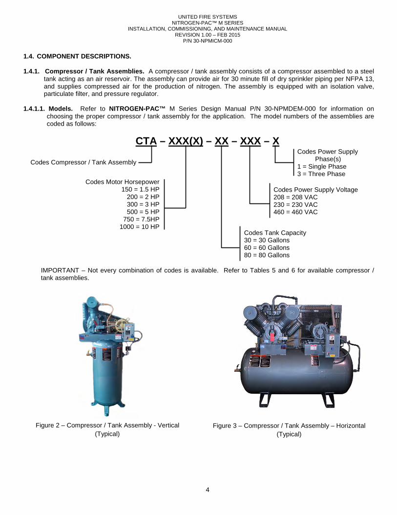
1.4. COMPONENT DESCRIPTIONS. 1.4.1. Compressor / Tank Assemblies. A compressor / tank assembly consists of a compressor assembled to a steel
tank acting as an air reservoir. The assembly can provide air for 30 minute fill of dry sprinkler piping per NFPA 13, and supplies compressed air for the production of nitrogen. The assembly is equipped with an isolation valve, particulate filter, and pressure regulator.
1.4.1.1. Models. Refer to NITROGEN-PAC™ M Series Design Manual P/N 30-NPMDEM-000 for information on
choosing the proper compressor / tank assembly for the application. The model numbers of the assemblies are coded as follows:
CTA – XXX(X) – XX – XXX – X
IMPORTANT – Not every combination of codes is available. Refer to Tables 5 and 6 for available compressor / tank assemblies.
Figure 2 – Compressor / Tank Assembly - Vertical (Typical)
Codes Compressor / Tank Assembly
Codes Motor Horsepower 150 = 1.5 HP
200 = 2 HP 300 = 3 HP 500 = 5 HP
750 = 7.5HP 1000 = 10 HP
Codes Power Supply Phase(s)
1 = Single Phase 3 = Three Phase
Codes Power Supply Voltage 208 = 208 VAC 230 = 230 VAC 460 = 460 VAC
Codes Tank Capacity 30 = 30 Gallons 60 = 60 Gallons 80 = 80 Gallons
Figure 3 – Compressor / Tank Assembly – Horizontal (Typical)
UNITED FIRE SYSTEMS NITROGEN-PAC™ M SERIES
INSTALLATION, COMMISSIONING, AND MAINTENANCE MANUAL REVISION 1.00 – FEB 2015
P/N 30-NPMICM-000
5
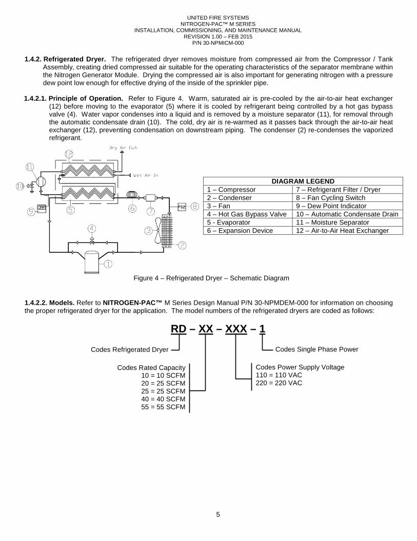
1.4.2. Refrigerated Dryer. The refrigerated dryer removes moisture from compressed air from the Compressor / Tank Assembly, creating dried compressed air suitable for the operating characteristics of the separator membrane within the Nitrogen Generator Module. Drying the compressed air is also important for generating nitrogen with a pressure dew point low enough for effective drying of the inside of the sprinkler pipe.
1.4.2.1. Principle of Operation. Refer to Figure 4. Warm, saturated air is pre-cooled by the air-to-air heat exchanger
(12) before moving to the evaporator (5) where it is cooled by refrigerant being controlled by a hot gas bypass valve (4). Water vapor condenses into a liquid and is removed by a moisture separator (11), for removal through the automatic condensate drain (10). The cold, dry air is re-warmed as it passes back through the air-to-air heat exchanger (12), preventing condensation on downstream piping. The condenser (2) re-condenses the vaporized refrigerant.
1.4.2.2. Models. Refer to NITROGEN-PAC™ M Series Design Manual P/N 30-NPMDEM-000 for information on choosing the proper refrigerated dryer for the application. The model numbers of the refrigerated dryers are coded as follows:
RD – XX – XXX – 1
DIAGRAM LEGEND 1 – Compressor 7 – Refrigerant Filter / Dryer 2 – Condenser 8 – Fan Cycling Switch 3 – Fan 9 – Dew Point Indicator 4 – Hot Gas Bypass Valve 10 – Automatic Condensate Drain 5 - Evaporator 11 – Moisture Separator 6 – Expansion Device 12 – Air-to-Air Heat Exchanger
Figure 4 – Refrigerated Dryer – Schematic Diagram
Codes Refrigerated Dryer
Codes Rated Capacity 10 = 10 SCFM 20 = 25 SCFM 25 = 25 SCFM 40 = 40 SCFM 55 = 55 SCFM
Codes Single Phase Power
Codes Power Supply Voltage 110 = 110 VAC 220 = 220 VAC
INSTALLATION,
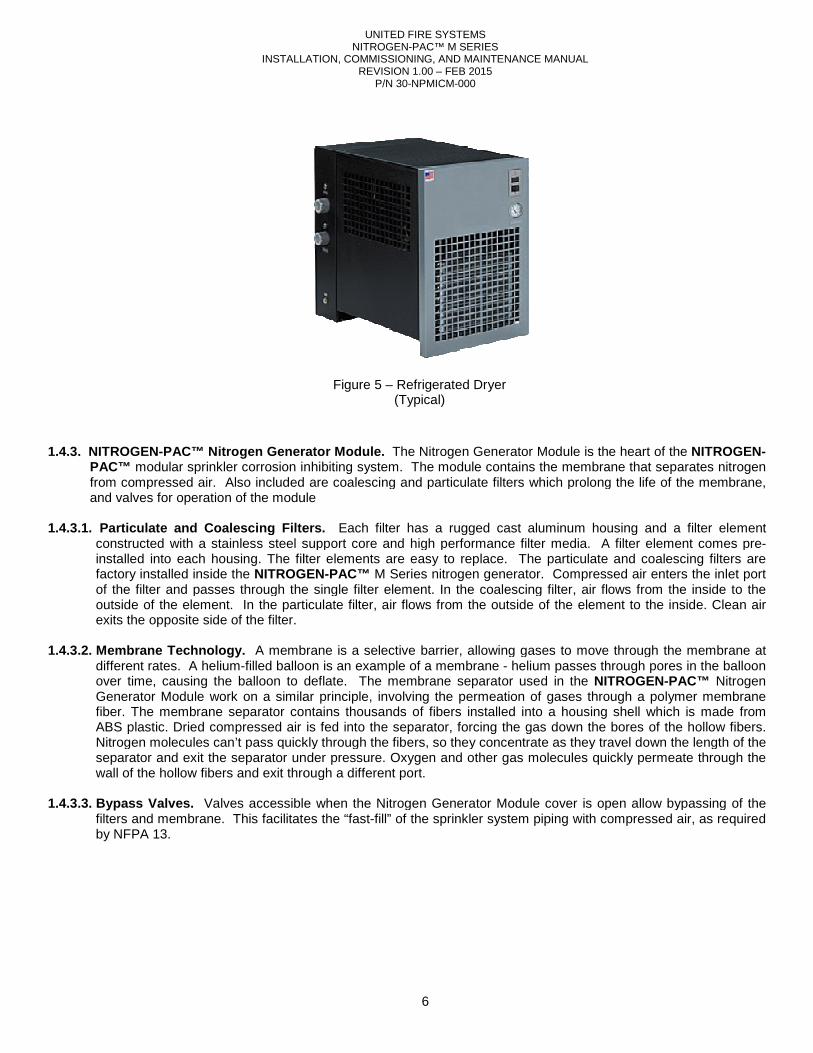
1.4.3. NITROGEN-PAC™ Nitrogen Generator Module.
PAC™ modular sprinkler corrosion inhibiting system. The module contains the membrane that separates nitrogen from compressed air. Also included are coalescing and particulate filters which prolong the life of the membrane, and valves for operation of the module
1.4.3.1. Particulate and Coalescing Filters.
constructed with a stainless steel support core and high performance filter media.installed into each housing. The filter elements are easy to replace.factory installed inside the NITROGENof the filter and passes through the single filter element.outside of the element. In the particulateexits the opposite side of the filter.
1.4.3.2. Membrane Technology. A membrane is a selective barrier, allowing gases to move through the membrane at
different rates. A helium-filled balloon is an example of a membrane over time, causing the balloon to deflate. The membrane seGenerator Module work on a similar principle, involving the permeation of gases through a polymer membrane fiber. The membrane separator contains thousands of fibers installed into a housing shell which is made frABS plastic. Dried compressed air is fed into the separator, forcing the gas down the bores of the hollow fibers. Nitrogen molecules can’t pass quickly through the fibersseparator and exit the separator under pressure. wall of the hollow fibers and exit through a different port.
1.4.3.3. Bypass Valves. Valves accessible when the Nitrogen Generator Module cover is open allow bypassing of the
filters and membrane. This facilitates the “fastby NFPA 13.
UNITED FIRE SYSTEMS NITROGEN-PAC™ M SERIES
INSTALLATION, COMMISSIONING, AND MAINTENANCE MANUAL REVISION 1.00 – FEB 2015
P/N 30-NPMICM-000
6
PAC™ Nitrogen Generator Module. The Nitrogen Generator Module is the heart of the modular sprinkler corrosion inhibiting system. The module contains the membrane that separates nitrogen
from compressed air. Also included are coalescing and particulate filters which prolong the life of the membrane, ule
Particulate and Coalescing Filters. Each filter has a rugged cast aluminum housing and a filter element stainless steel support core and high performance filter media. A filter element comes pre
ilter elements are easy to replace. The particulate and coalescing filters are NITROGEN-PAC™ M Series nitrogen generator. Compressed air enters the inlet
and passes through the single filter element. In the coalescing filter, air flows from the inside to the particulate filter, air flows from the outside of the element to the inside. Clean air
A membrane is a selective barrier, allowing gases to move through the membrane at filled balloon is an example of a membrane - helium passes through pores in the balloon
over time, causing the balloon to deflate. The membrane separator used in the NITROGENGenerator Module work on a similar principle, involving the permeation of gases through a polymer membrane fiber. The membrane separator contains thousands of fibers installed into a housing shell which is made frABS plastic. Dried compressed air is fed into the separator, forcing the gas down the bores of the hollow fibers. Nitrogen molecules can’t pass quickly through the fibers, so they concentrate as they travel down the length of the
separator under pressure. Oxygen and other gas molecules quickly permeate through the wall of the hollow fibers and exit through a different port.
Valves accessible when the Nitrogen Generator Module cover is open allow bypassing of the filters and membrane. This facilitates the “fast-fill” of the sprinkler system piping with compressed air, as required
Figure 5 – Refrigerated Dryer
(Typical)
The Nitrogen Generator Module is the heart of the NITROGEN-modular sprinkler corrosion inhibiting system. The module contains the membrane that separates nitrogen
from compressed air. Also included are coalescing and particulate filters which prolong the life of the membrane,
a rugged cast aluminum housing and a filter element A filter element comes pre-
The particulate and coalescing filters are Compressed air enters the inlet port
coalescing filter, air flows from the inside to the from the outside of the element to the inside. Clean air
A membrane is a selective barrier, allowing gases to move through the membrane at helium passes through pores in the balloon
NITROGEN-PAC™ Nitrogen Generator Module work on a similar principle, involving the permeation of gases through a polymer membrane fiber. The membrane separator contains thousands of fibers installed into a housing shell which is made from ABS plastic. Dried compressed air is fed into the separator, forcing the gas down the bores of the hollow fibers.
so they concentrate as they travel down the length of the ther gas molecules quickly permeate through the
Valves accessible when the Nitrogen Generator Module cover is open allow bypassing of the fill” of the sprinkler system piping with compressed air, as required
INSTALLATION,
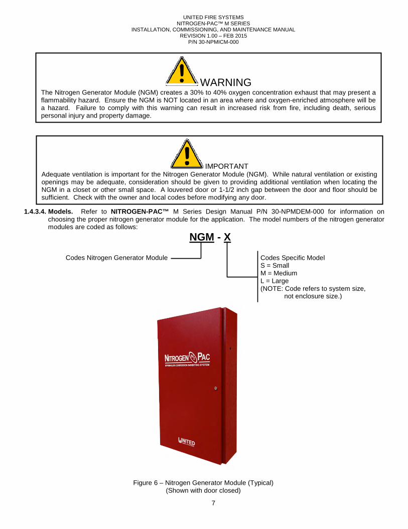
1.4.3.4. Models. Refer to NITROGEN-PAC™
choosing the proper nitrogen generator module for the application. The model numbers of the nitrogen generator modules are coded as follows:
Codes Nitrogen Generator Module
Figure
Adequate ventilation is important for the Nitrogen Generator Module (NGM). While natural ventilation or existing openings may be adequate, consideration should be given to providing additional ventilation when locating the NGM in a closet or other small space. A louvered door or 1sufficient. Check with the owner and local codes before modifying any door.
The Nitrogen Generator Module (NGM) creates a 30% to 40% oxygen concentration exhaust that may present a flammability hazard. Ensure the NGM is NOT located in an area where and oxygena hazard. Failure to comply with this warning can result in increased risk from fire, including death, serious personal injury and property damage.
UNITED FIRE SYSTEMS NITROGEN-PAC™ M SERIES
INSTALLATION, COMMISSIONING, AND MAINTENANCE MANUAL REVISION 1.00 – FEB 2015
P/N 30-NPMICM-000
7
PAC™ M Series Design Manual P/N 30-NPMDEMchoosing the proper nitrogen generator module for the application. The model numbers of the nitrogen generator
NGM - X
Codes Nitrogen Generator Module Codes Specific ModelS = Small M = Medium L = Large (NOTE: Code refers to system size,
not enclosure size.)
Figure 6 – Nitrogen Generator Module (Typical) (Shown with door closed)
IMPORTANT Adequate ventilation is important for the Nitrogen Generator Module (NGM). While natural ventilation or existing openings may be adequate, consideration should be given to providing additional ventilation when locating the
closet or other small space. A louvered door or 1-1/2 inch gap between the door and floor should be sufficient. Check with the owner and local codes before modifying any door.
WARNING The Nitrogen Generator Module (NGM) creates a 30% to 40% oxygen concentration exhaust that may present a
mability hazard. Ensure the NGM is NOT located in an area where and oxygen-enriched atmosphere will be a hazard. Failure to comply with this warning can result in increased risk from fire, including death, serious
NPMDEM-000 for information on choosing the proper nitrogen generator module for the application. The model numbers of the nitrogen generator
Codes Specific Model
Code refers to system size, not enclosure size.)
Adequate ventilation is important for the Nitrogen Generator Module (NGM). While natural ventilation or existing openings may be adequate, consideration should be given to providing additional ventilation when locating the
1/2 inch gap between the door and floor should be
The Nitrogen Generator Module (NGM) creates a 30% to 40% oxygen concentration exhaust that may present a enriched atmosphere will be
a hazard. Failure to comply with this warning can result in increased risk from fire, including death, serious
UNITED FIRE SYSTEMS NITROGEN-PAC™ M SERIES
INSTALLATION, COMMISSIONING, AND MAINTENANCE MANUAL REVISION 1.00 – FEB 2015
P/N 30-NPMICM-000
8
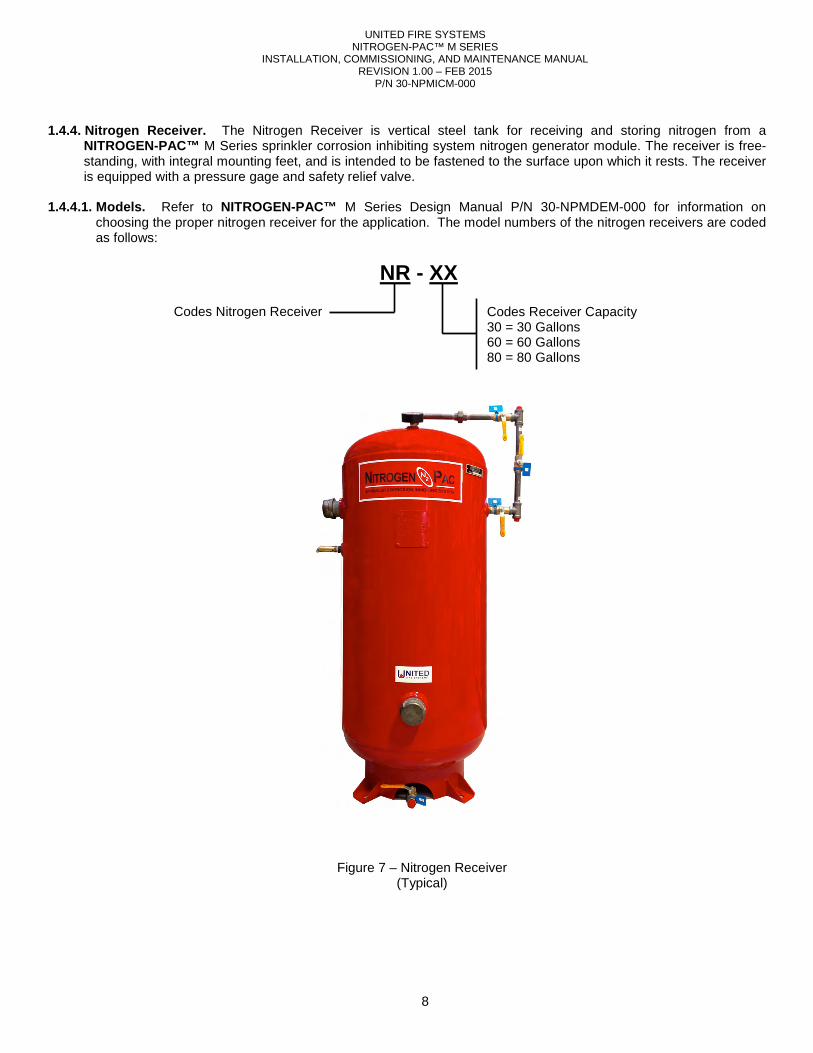
1.4.4. Nitrogen Receiver. The Nitrogen Receiver is vertical steel tank for receiving and storing nitrogen from a
NITROGEN-PAC™ M Series sprinkler corrosion inhibiting system nitrogen generator module. The receiver is free-standing, with integral mounting feet, and is intended to be fastened to the surface upon which it rests. The receiver is equipped with a pressure gage and safety relief valve.
1.4.4.1. Models. Refer to NITROGEN-PAC™ M Series Design Manual P/N 30-NPMDEM-000 for information on
choosing the proper nitrogen receiver for the application. The model numbers of the nitrogen receivers are coded as follows:
NR - XX
Codes Nitrogen Receiver Codes Receiver Capacity 30 = 30 Gallons 60 = 60 Gallons 80 = 80 Gallons
Figure 7 – Nitrogen Receiver (Typical)
UNITED FIRE SYSTEMS NITROGEN-PAC™ M SERIES
INSTALLATION, COMMISSIONING, AND MAINTENANCE MANUAL REVISION 1.00 – FEB 2015
P/N 30-NPMICM-000
9
1.4.5. Purge Vent Assembly – Fixed Orifice Model PVA-1. This device purges gas from the interior of the sprinkler pipe, allowing the NITROGEN-PAC™ system to replace air with nitrogen, and also allowing nitrogen to remove liquid water from inside the pipe. This assembly can be connected to the sprinkler piping in the vicinity of the inspector’s test connection or near the sprinkler valve. A float valve prevents the escape of water when the preaction valve opens and the sprinkler piping fills with water. A fixed orifice regulates the amount of gas leaving the pipe. The purge vent also serves as a connection point for an N2 Purity Analyzer – Hand-Held Model NA-1 to assess the percent of nitrogen in the pipe.
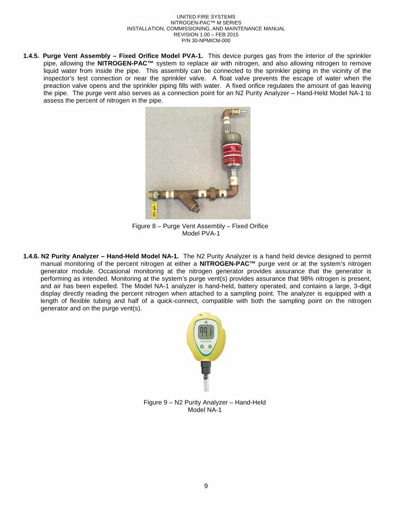
1.4.6. N2 Purity Analyzer – Hand-Held Model NA-1. The N2 Purity Analyzer is a hand held device designed to permit
manual monitoring of the percent nitrogen at either a NITROGEN-PAC™ purge vent or at the system’s nitrogen generator module. Occasional monitoring at the nitrogen generator provides assurance that the generator is performing as intended. Monitoring at the system’s purge vent(s) provides assurance that 98% nitrogen is present, and air has been expelled. The Model NA-1 analyzer is hand-held, battery operated, and contains a large, 3-digit display directly reading the percent nitrogen when attached to a sampling point. The analyzer is equipped with a length of flexible tubing and half of a quick-connect, compatible with both the sampling point on the nitrogen generator and on the purge vent(s).
Figure 9 – N2 Purity Analyzer – Hand-Held Model NA-1
Figure 8 – Purge Vent Assembly – Fixed Orifice Model PVA-1
UNITED FIRE SYSTEMS NITROGEN-PAC™ M SERIES
INSTALLATION, COMMISSIONING, AND MAINTENANCE MANUAL REVISION 1.00 – FEB 2015
P/N 30-NPMICM-000
10
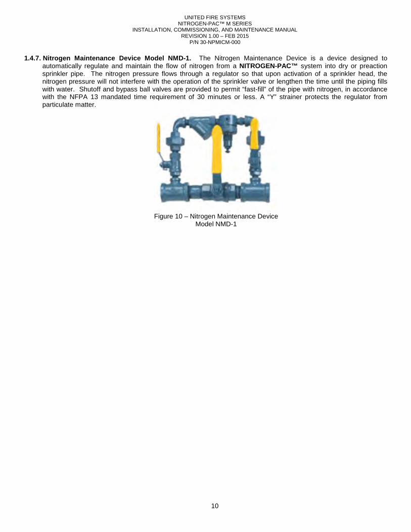
1.4.7. Nitrogen Maintenance Device Model NMD-1. The Nitrogen Maintenance Device is a device designed to automatically regulate and maintain the flow of nitrogen from a NITROGEN-PAC™ system into dry or preaction sprinkler pipe. The nitrogen pressure flows through a regulator so that upon activation of a sprinkler head, the nitrogen pressure will not interfere with the operation of the sprinkler valve or lengthen the time until the piping fills with water. Shutoff and bypass ball valves are provided to permit “fast-fill” of the pipe with nitrogen, in accordance with the NFPA 13 mandated time requirement of 30 minutes or less. A “Y” strainer protects the regulator from particulate matter.
Figure 10 – Nitrogen Maintenance Device Model NMD-1
INSTALLATION, COMMISSIONING, AND MAINTENANCE MANUAL
2. INSTALLATION
2.1. Unpacking. Check shipment of the United Fire Systems
damage. If there is any damage or missing parts, the transportation company's agent should make a effect on the Bill of Lading. Claims should be settled directly with the transportation company.were received in the shipment as ordered. Contact the factory immediately if there are any missing parts or discrepancies.
2.2. Equipment Locations. Due consideration must be given to all of the following considerations when locating equipment.
2.2.1. Engineering D rawings (if available).
equipment per these drawings. 2.2.2. Proximity. NITROGEN-PAC™ equipment should be installed in reasonably close proximity to the system riser(s)
being protected. The most logical location is in the same sprinkler room as the riser(s). If necessary, the equipment may be installed remotely. remote locations is connected together.
2.2.3. Weight. Carefully check the applicable tables for the weight of each piece of equipment.
surface, whether horizontal or vertical, is capable of supporting the weight, with a clear safety margin. Consult a structural engineer when necessary to verify
2.2.4. Noise. Motor-operated NITROGEN-
do emit noise when running. Consideration should be given to locating equipment where normal operating noise does not interfere with building operations.
2.2.5. Clearance. Sufficient clearance s hould be available after installation for maintenance operations to take place on
equipment. Leave at least (3) feet of clearance for personnel to access equipment for maintenance. The NITROGEN-PAC™ Nitrogen Generator Module has a hinged door. Allow sufswung completely open.
Understand and follow all safety recommendations when moving heavy pieces of equipment. Equipment may be easily tipped over when moving. Failure to use caution can result in equipment damage and personal injury.
Rapid release of nitrogen gas into an enclosed space displaces oxygen and can cause an asphyxiation hazard. Inhalation of nitrogen in increased concentration can result in unconsciousness and asphyxiation without warning. All areas containing nitrogen system equipment MUST be adequately ventilated. All nitrogen gas leaks discovered during installation, commissioning, and maintenance of M Series nitrogen generating equipment MUST be corrected promptly. Failure to comply can result in death or serious personal injury.
UNITED FIRE SYSTEMS NITROGEN-PAC™ M SERIES
INSTALLATION, COMMISSIONING, AND MAINTENANCE MANUAL REVISION 1.00 – FEB 2015
P/N 30-NPMICM-000
11
Check shipment of the United Fire Systems NITROGEN-PAC™ system packaging and equipment for . If there is any damage or missing parts, the transportation company's agent should make a
effect on the Bill of Lading. Claims should be settled directly with the transportation company.were received in the shipment as ordered. Contact the factory immediately if there are any missing parts or
Due consideration must be given to all of the following considerations when locating
rawings (if available). If a survey was conducted, and engineering drawings prepared, locate all
equipment should be installed in reasonably close proximity to the system riser(s) being protected. The most logical location is in the same sprinkler room as the riser(s). If necessary, the equipment may be installed remotely. Documentation and signage should be clear to identify which equipment in remote locations is connected together.
Carefully check the applicable tables for the weight of each piece of equipment.surface, whether horizontal or vertical, is capable of supporting the weight, with a clear safety margin. Consult a structural engineer when necessary to verify suitability of locations.
-PAC™ equipment (Compressor / Tank Assemblies and Refrigerated Dryers) do emit noise when running. Consideration should be given to locating equipment where normal operating noise does not interfere with building operations.
hould be available after installation for maintenance operations to take place on equipment. Leave at least (3) feet of clearance for personnel to access equipment for maintenance. The
Nitrogen Generator Module has a hinged door. Allow sufficient clearance for the door to be
CAUTION Understand and follow all safety recommendations when moving heavy pieces of equipment. Equipment may be
easily tipped over when moving. Failure to use caution can result in equipment damage and personal injury.
DANGER Rapid release of nitrogen gas into an enclosed space displaces oxygen and can cause an asphyxiation hazard. Inhalation of nitrogen in increased concentration can result in unconsciousness and asphyxiation without warning.
areas containing nitrogen system equipment MUST be adequately ventilated. All nitrogen gas leaks discovered during installation, commissioning, and maintenance of M Series nitrogen generating equipment MUST be corrected
sult in death or serious personal injury.
system packaging and equipment for . If there is any damage or missing parts, the transportation company's agent should make a notation to the
effect on the Bill of Lading. Claims should be settled directly with the transportation company. Verify that all parts were received in the shipment as ordered. Contact the factory immediately if there are any missing parts or
Due consideration must be given to all of the following considerations when locating
If a survey was conducted, and engineering drawings prepared, locate all
equipment should be installed in reasonably close proximity to the system riser(s) being protected. The most logical location is in the same sprinkler room as the riser(s). If necessary, the
Documentation and signage should be clear to identify which equipment in
Carefully check the applicable tables for the weight of each piece of equipment. Ensure that the mounting surface, whether horizontal or vertical, is capable of supporting the weight, with a clear safety margin. Consult a
Compressor / Tank Assemblies and Refrigerated Dryers) do emit noise when running. Consideration should be given to locating equipment where normal operating noise
hould be available after installation for maintenance operations to take place on equipment. Leave at least (3) feet of clearance for personnel to access equipment for maintenance. The
ficient clearance for the door to be
Understand and follow all safety recommendations when moving heavy pieces of equipment. Equipment may be easily tipped over when moving. Failure to use caution can result in equipment damage and personal injury.
Rapid release of nitrogen gas into an enclosed space displaces oxygen and can cause an asphyxiation hazard. Inhalation of nitrogen in increased concentration can result in unconsciousness and asphyxiation without warning.
areas containing nitrogen system equipment MUST be adequately ventilated. All nitrogen gas leaks discovered during installation, commissioning, and maintenance of M Series nitrogen generating equipment MUST be corrected
UNITED FIRE SYSTEMS NITROGEN-PAC™ M SERIES
INSTALLATION, COMMISSIONING, AND MAINTENANCE MANUAL REVISION 1.00 – FEB 2015
P/N 30-NPMICM-000
12
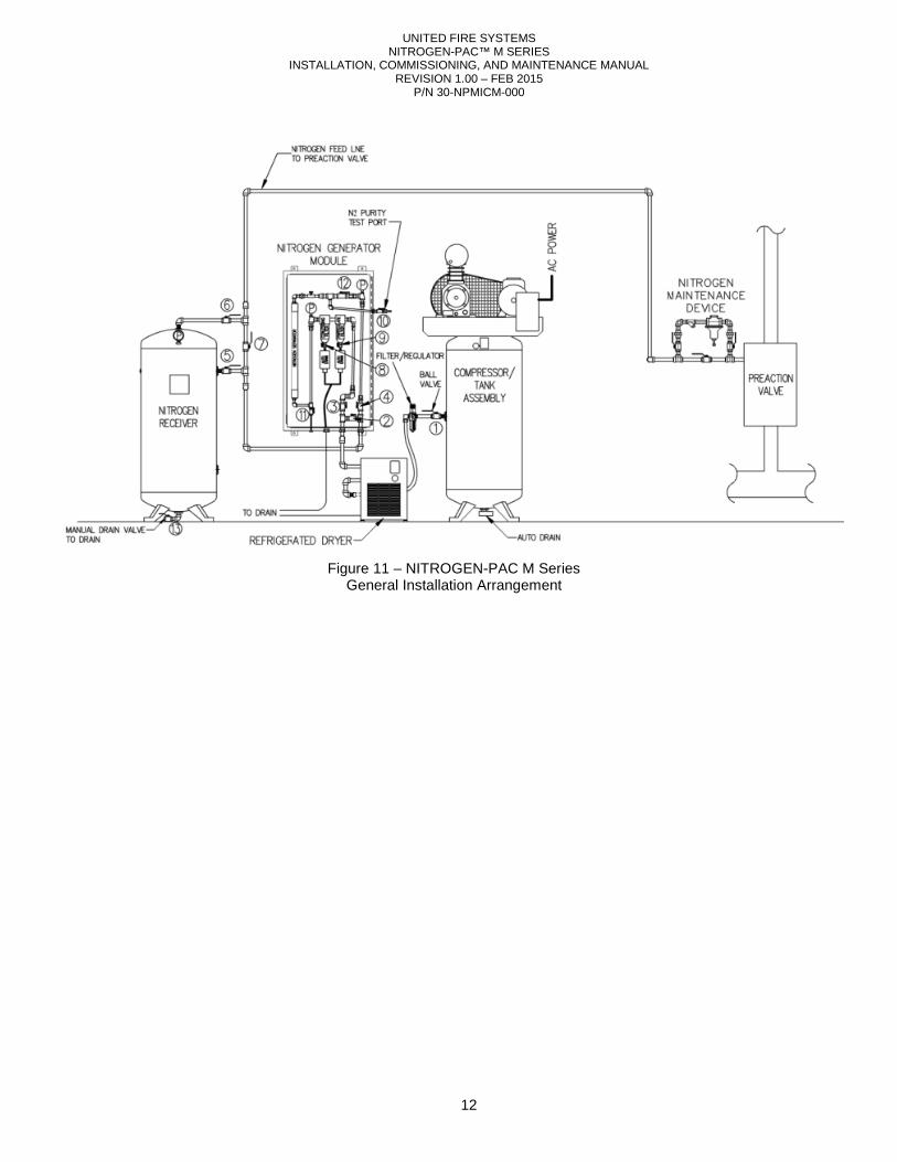
Figure 11 – NITROGEN-PAC M Series General Installation Arrangement
UNITED FIRE SYSTEMS NITROGEN-PAC™ M SERIES
INSTALLATION, COMMISSIONING, AND MAINTENANCE MANUAL REVISION 1.00 – FEB 2015
P/N 30-NPMICM-000
13
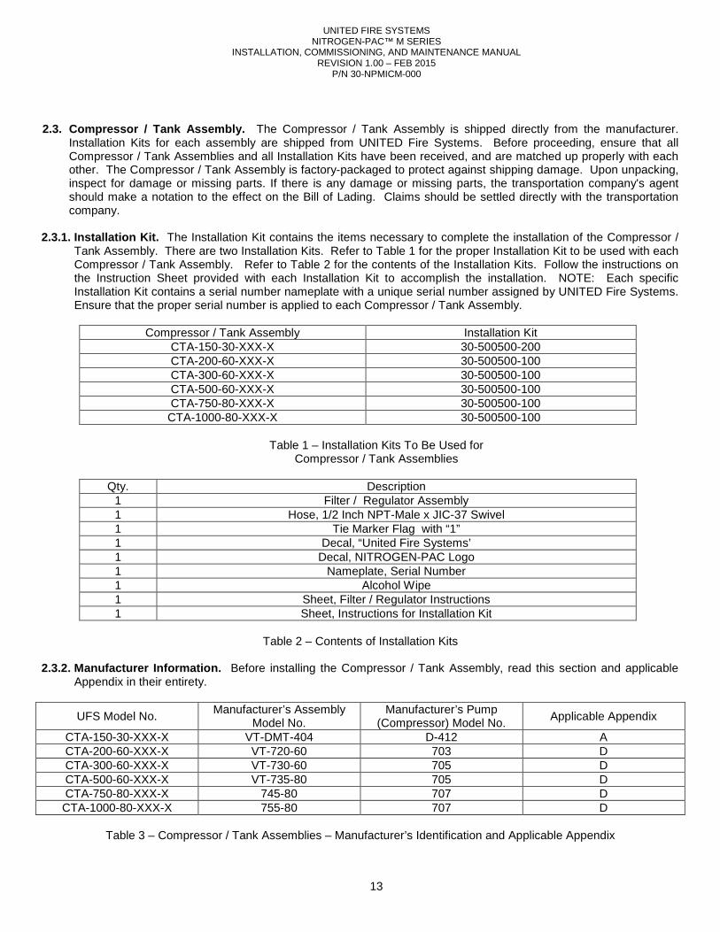
2.3. Compressor / Tank Assembly. The Compressor / Tank Assembly is shipped directly from the manufacturer.
Installation Kits for each assembly are shipped from UNITED Fire Systems. Before proceeding, ensure that all Compressor / Tank Assemblies and all Installation Kits have been received, and are matched up properly with each other. The Compressor / Tank Assembly is factory-packaged to protect against shipping damage. Upon unpacking, inspect for damage or missing parts. If there is any damage or missing parts, the transportation company's agent should make a notation to the effect on the Bill of Lading. Claims should be settled directly with the transportation company.
2.3.1. Installation Kit. The Installation Kit contains the items necessary to complete the installation of the Compressor /
Tank Assembly. There are two Installation Kits. Refer to Table 1 for the proper Installation Kit to be used with each Compressor / Tank Assembly. Refer to Table 2 for the contents of the Installation Kits. Follow the instructions on the Instruction Sheet provided with each Installation Kit to accomplish the installation. NOTE: Each specific Installation Kit contains a serial number nameplate with a unique serial number assigned by UNITED Fire Systems. Ensure that the proper serial number is applied to each Compressor / Tank Assembly.
Compressor / Tank Assembly Installation Kit CTA-150-30-XXX-X 30-500500-200 CTA-200-60-XXX-X 30-500500-100 CTA-300-60-XXX-X 30-500500-100 CTA-500-60-XXX-X 30-500500-100 CTA-750-80-XXX-X 30-500500-100 CTA-1000-80-XXX-X 30-500500-100
Table 1 – Installation Kits To Be Used for
Compressor / Tank Assemblies
Qty. Description 1 Filter / Regulator Assembly 1 Hose, 1/2 Inch NPT-Male x JIC-37 Swivel 1 Tie Marker Flag with “1” 1 Decal, “United Fire Systems’ 1 Decal, NITROGEN-PAC Logo 1 Nameplate, Serial Number 1 Alcohol Wipe 1 Sheet, Filter / Regulator Instructions 1 Sheet, Instructions for Installation Kit
Table 2 – Contents of Installation Kits
2.3.2. Manufacturer Information. Before installing the Compressor / Tank Assembly, read this section and applicable
Appendix in their entirety.
UFS Model No. Manufacturer’s Assembly
Model No. Manufacturer’s Pump
(Compressor) Model No. Applicable Appendix
CTA-150-30-XXX-X VT-DMT-404 D-412 A CTA-200-60-XXX-X VT-720-60 703 D CTA-300-60-XXX-X VT-730-60 705 D CTA-500-60-XXX-X VT-735-80 705 D CTA-750-80-XXX-X 745-80 707 D CTA-1000-80-XXX-X 755-80 707 D
Table 3 – Compressor / Tank Assemblies – Manufacturer’s Identification and Applicable Appendix
INSTALLATION, COMMISSIONING, AND MAINTENANCE MANUAL
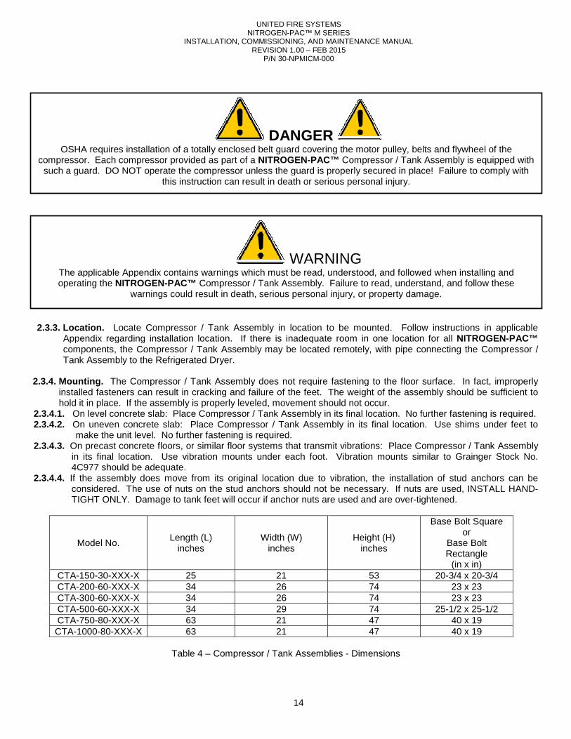
2.3.3. Location. Locate Compressor / Tank A
Appendix regarding installation location.components, the Compressor / Tank Assembly may be located remotely, with pipe connecting the Compressor / Tank Assembly to the Refrigerated Dryer.
2.3.4. Mounting. The Compressor / Tank Assembly does not require fastening to the floor surface. In fact, improperly
installed fasteners can result in cracking and failure of the feet. The weight of the assembly should be sufficient to hold it in place. If the assembly is properly
2.3.4.1. On level concrete slab: Place Compressor / Tank Assembly in its final location. No further fastening is required.2.3.4.2. On uneven concrete slab: Place Compressor / Tank Assembly in its final location. Use
make the unit level. No further fastening is required.2.3.4.3. On precast concrete floors, or similar floor systems that transmit vibrations: Place Compressor / Tank Assembly
in its final location. Use vibration mounts under each foot. Vib4C977 should be adequate.
2.3.4.4. If the assembly does move from its original location due to vibration, the installation of stud anchors can be considered. The use of nuts on the stud anchors should not be necessary. If nuts are used, INSTALL HANDTIGHT ONLY. Damage to tank feet will
Model No. Length (L)
inches
CTA-150-30-XXX-X 25 CTA-200-60-XXX-X 34 CTA-300-60-XXX-X 34 CTA-500-60-XXX-X 34 CTA-750-80-XXX-X 63 CTA-1000-80-XXX-X 63
Table 4 – Compressor / Tank Assemblies
OSHA requires installation of a totally enclosed belt guard covering the motor pulley, belts and flywheel of the compressor. Each compressor provided as part of a
such a guard. DO NOT operate the compressor unless the guard is properly secured in place! Failure to comply with this instruction can result in death or serious personal injury.
The applicable Appendix contains warnings which must be read, understood, and followed when installing and operating the NITROGEN-PAC™ Compressor / Tank Assembly. Failure to read, understand, and follow these
warnings could result in death, serious person
UNITED FIRE SYSTEMS NITROGEN-PAC™ M SERIES
INSTALLATION, COMMISSIONING, AND MAINTENANCE MANUAL REVISION 1.00 – FEB 2015
P/N 30-NPMICM-000
14
Tank Assembly in location to be mounted. Follow instructions inAppendix regarding installation location. If there is inadequate room in one location for all components, the Compressor / Tank Assembly may be located remotely, with pipe connecting the Compressor / Tank Assembly to the Refrigerated Dryer.
The Compressor / Tank Assembly does not require fastening to the floor surface. In fact, improperly installed fasteners can result in cracking and failure of the feet. The weight of the assembly should be sufficient to
properly leveled, movement should not occur. On level concrete slab: Place Compressor / Tank Assembly in its final location. No further fastening is required.On uneven concrete slab: Place Compressor / Tank Assembly in its final location. Use make the unit level. No further fastening is required.
On precast concrete floors, or similar floor systems that transmit vibrations: Place Compressor / Tank Assembly in its final location. Use vibration mounts under each foot. Vibration mounts similar to Grainger Stock No.
If the assembly does move from its original location due to vibration, the installation of stud anchors can be considered. The use of nuts on the stud anchors should not be necessary. If nuts are used, INSTALL HANDTIGHT ONLY. Damage to tank feet will occur if anchor nuts are used and are over-tightened.
Width (W) inches
Height (H) inches
21 53 26 74 26 74 29 74 21 47 21 47
Compressor / Tank Assemblies - Dimensions
DANGER OSHA requires installation of a totally enclosed belt guard covering the motor pulley, belts and flywheel of the
compressor. Each compressor provided as part of a NITROGEN-PAC™ Compressor / Tank Assembly is equipped with such a guard. DO NOT operate the compressor unless the guard is properly secured in place! Failure to comply with
this instruction can result in death or serious personal injury.
WARNING The applicable Appendix contains warnings which must be read, understood, and followed when installing and
Compressor / Tank Assembly. Failure to read, understand, and follow these warnings could result in death, serious personal injury, or property damage.
Follow instructions in applicable If there is inadequate room in one location for all NITROGEN-PAC™
components, the Compressor / Tank Assembly may be located remotely, with pipe connecting the Compressor /
The Compressor / Tank Assembly does not require fastening to the floor surface. In fact, improperly installed fasteners can result in cracking and failure of the feet. The weight of the assembly should be sufficient to
On level concrete slab: Place Compressor / Tank Assembly in its final location. No further fastening is required. On uneven concrete slab: Place Compressor / Tank Assembly in its final location. Use shims under feet to
On precast concrete floors, or similar floor systems that transmit vibrations: Place Compressor / Tank Assembly ration mounts similar to Grainger Stock No.
If the assembly does move from its original location due to vibration, the installation of stud anchors can be considered. The use of nuts on the stud anchors should not be necessary. If nuts are used, INSTALL HAND-
tightened.
Base Bolt Square or
Base Bolt Rectangle
(in x in) 20-3/4 x 20-3/4
23 x 23 23 x 23
25-1/2 x 25-1/2 40 x 19 40 x 19
OSHA requires installation of a totally enclosed belt guard covering the motor pulley, belts and flywheel of the Compressor / Tank Assembly is equipped with
such a guard. DO NOT operate the compressor unless the guard is properly secured in place! Failure to comply with
The applicable Appendix contains warnings which must be read, understood, and followed when installing and Compressor / Tank Assembly. Failure to read, understand, and follow these
al injury, or property damage.
INSTALLATION, COMMISSIONING, AND MAINTENANCE MANUAL
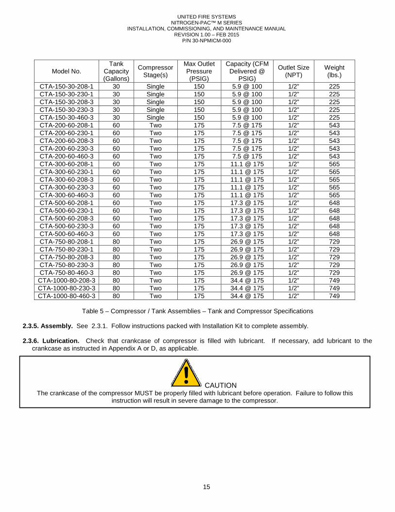
Model No. Tank
Capacity (Gallons)
Compressor Stage(s)
CTA-150-30-208-1 30 SingleCTA-150-30-230-1 30 SingleCTA-150-30-208-3 30 SingleCTA-150-30-230-3 30 SingleCTA-150-30-460-3 30 SingleCTA-200-60-208-1 60 CTA-200-60-230-1 60 CTA-200-60-208-3 60 CTA-200-60-230-3 60 CTA-200-60-460-3 60 CTA-300-60-208-1 60 CTA-300-60-230-1 60 CTA-300-60-208-3 60 CTA-300-60-230-3 60 CTA-300-60-460-3 60 CTA-500-60-208-1 60 CTA-500-60-230-1 60 CTA-500-60-208-3 60 CTA-500-60-230-3 60 CTA-500-60-460-3 60 CTA-750-80-208-1 80 CTA-750-80-230-1 80 CTA-750-80-208-3 80 CTA-750-80-230-3 80 CTA-750-80-460-3 80 CTA-1000-80-208-3 80 CTA-1000-80-230-3 80 CTA-1000-80-460-3 80
Table 5 – Compressor / Tank Assemblies
2.3.5. Assembly. See 2.3.1. Follow instructions packed with Installation Kit to complete assembly. 2.3.6. Lubrication. Check that crankcase of compressor is filled with lubricant. If necessary, add lubricant to the
crankcase as instructed in Appendix A or
The crankcase of the compressor MUST be properly filled with lubricant before instruction will result in severe damage to the compressor.
UNITED FIRE SYSTEMS NITROGEN-PAC™ M SERIES
INSTALLATION, COMMISSIONING, AND MAINTENANCE MANUAL REVISION 1.00 – FEB 2015
P/N 30-NPMICM-000
15
Compressor Stage(s)
Max Outlet Pressure (PSIG)
Capacity (CFM Delivered @
PSIG)
Outlet Size (NPT)
Single 150 5.9 @ 100 1/2”Single 150 5.9 @ 100 1/2”Single 150 5.9 @ 100 1/2”Single 150 5.9 @ 100 1/2”Single 150 5.9 @ 100 1/2”Two 175 7.5 @ 175 1/2”Two 175 7.5 @ 175 1/2”Two 175 7.5 @ 175 1/2”Two 175 7.5 @ 175 1/2”Two 175 7.5 @ 175 1/2”Two 175 11.1 @ 175 1/2”Two 175 11.1 @ 175 1/2”Two 175 11.1 @ 175 1/2”Two 175 11.1 @ 175 1/2”Two 175 11.1 @ 175 1/2”Two 175 17.3 @ 175 1/2”Two 175 17.3 @ 175 1/2”Two 175 17.3 @ 175 1/2”Two 175 17.3 @ 175 1/2”Two 175 17.3 @ 175 1/2”Two 175 26.9 @ 175 1/2”Two 175 26.9 @ 175 1/2”Two 175 26.9 @ 175 1/2”Two 175 26.9 @ 175 1/2”Two 175 26.9 @ 175 1/2”Two 175 34.4 @ 175 1/2”Two 175 34.4 @ 175 1/2”Two 175 34.4 @ 175 1/2”
Compressor / Tank Assemblies – Tank and Compressor Specifications
2.3.1. Follow instructions packed with Installation Kit to complete assembly.
Check that crankcase of compressor is filled with lubricant. If necessary, add lubricant to the or D, as applicable.
CAUTION The crankcase of the compressor MUST be properly filled with lubricant before operation. Failure to follow this
instruction will result in severe damage to the compressor.
Outlet Size (NPT)
Weight (lbs.)
1/2” 225 1/2” 225 1/2” 225 1/2” 225 1/2” 225 1/2” 543 1/2” 543 1/2” 543 1/2” 543 1/2” 543 1/2” 565 1/2” 565 1/2” 565 1/2” 565 1/2” 565 1/2” 648 1/2” 648 1/2” 648 1/2” 648 1/2” 648 1/2” 729 1/2” 729 1/2” 729 1/2” 729 1/2” 729 1/2” 749 1/2” 749 1/2” 749
Tank and Compressor Specifications
2.3.1. Follow instructions packed with Installation Kit to complete assembly.
Check that crankcase of compressor is filled with lubricant. If necessary, add lubricant to the
operation. Failure to follow this
INSTALLATION, COMMISSIONING, AND MAINTENANCE MANUAL
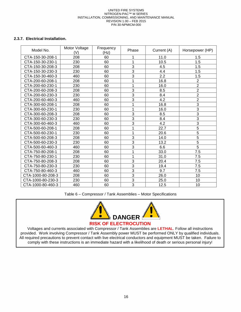
2.3.7. Electrical Installation.
Model No. Motor Voltage
(V) CTA-150-30-208-1 208 CTA-150-30-230-1 230 CTA-150-30-208-3 208 CTA-150-30-230-3 230 CTA-150-30-460-3 460 CTA-200-60-208-1 208 CTA-200-60-230-1 230 CTA-200-60-208-3 208 CTA-200-60-230-3 230 CTA-200-60-460-3 460 CTA-300-60-208-1 208 CTA-300-60-230-1 230 CTA-300-60-208-3 208 CTA-300-60-230-3 230 CTA-300-60-460-3 460 CTA-500-60-208-1 208 CTA-500-60-230-1 230 CTA-500-60-208-3 208 CTA-500-60-230-3 230 CTA-500-60-460-3 460 CTA-750-80-208-1 208 CTA-750-80-230-1 230 CTA-750-80-208-3 208 CTA-750-80-230-3 230 CTA-750-80-460-3 460 CTA-1000-80-208-3 208 CTA-1000-80-230-3 230 CTA-1000-80-460-3 460
Table 6 – Compressor / Tank Assemblies
RISK OF ELECTROCUTIONVoltages and currents associated with Compressor / Tank Assemblies are
provided. Work involving Compressor / Tank Assembly power MUST be performed ONLY by qualified individuals. All required precautions to prevent contact with live electrical conductors and equipment MUST be taken. Failure to
comply with these instructions is an immediate hazard with a likelihood of death or serious personal injury
UNITED FIRE SYSTEMS NITROGEN-PAC™ M SERIES
INSTALLATION, COMMISSIONING, AND MAINTENANCE MANUAL REVISION 1.00 – FEB 2015
P/N 30-NPMICM-000
16
Frequency (Hz)
Phase Current (A)
60 1 11.0 60 1 10.5 60 3 4.5 60 3 4.4 60 3 2.2 60 1 16.8 60 1 16.0 60 3 8.5 60 3 8.4 60 3 4.2 60 1 16.8 60 1 16.0 60 3 8.5 60 3 8.4 60 3 4.2 60 1 22.7 60 1 20.6 60 3 14.0 60 3 13.2 60 3 6.6 60 1 33.0 60 1 31.0 60 3 20.4 60 3 19.4 60 3 9.7 60 3 26.0 60 3 25.0 60 3 12.5
Compressor / Tank Assemblies – Motor Specifications
DANGER RISK OF ELECTROCUTION
Voltages and currents associated with Compressor / Tank Assemblies are LETHAL . Follow all instructions provided. Work involving Compressor / Tank Assembly power MUST be performed ONLY by qualified individuals.
precautions to prevent contact with live electrical conductors and equipment MUST be taken. Failure to an immediate hazard with a likelihood of death or serious personal injury
Horsepower (HP)
1.5 1.5 1.5 1.5 1.5 2 2 2 2 2 3 3 3 3 3 5 5 5 5 5
7.5 7.5 7.5 7.5 7.5 10 10 10
. Follow all instructions provided. Work involving Compressor / Tank Assembly power MUST be performed ONLY by qualified individuals.
precautions to prevent contact with live electrical conductors and equipment MUST be taken. Failure to an immediate hazard with a likelihood of death or serious personal injury!
UNITED FIRE SYSTEMS NITROGEN-PAC™ M SERIES
INSTALLATION, COMMISSIONING, AND MAINTENANCE MANUAL REVISION 1.00 – FEB 2015
P/N 30-NPMICM-000
17
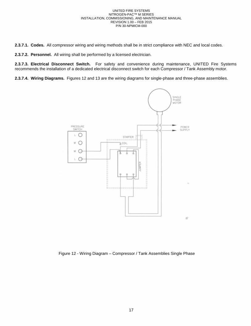
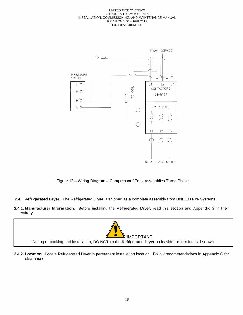
2.3.7.1. Codes. All compressor wiring and wiring methods shall be in strict compliance with NEC and local codes. 2.3.7.2. Personnel. All wiring shall be performed by a licensed electrician. 2.3.7.3. Electrical Disconnect Switch. For safety and convenience during maintenance, UNITED Fire Systems recommends the installation of a dedicated electrical disconnect switch for each Compressor / Tank Assembly motor. 2.3.7.4. Wiring Diagrams. Figures 12 and 13 are the wiring diagrams for single-phase and three-phase assemblies.
Figure 12 - Wiring Diagram – Compressor / Tank Assemblies Single Phase
INSTALLATION, COMMISSIONING, AND MAINTENANCE MANUAL
Figure 13 – Wiring Diagram
2.4. Refrigerated Dryer. The Refrigerated Dryer is 2.4.1. Manufacturer Information. Before installing the Refrigerated Dryer,
entirety. 2.4.2. Location. Locate Refrigerated D ryer in
clearances.
During unpacking and installation, DO NOT tip the Refrigerate
UNITED FIRE SYSTEMS NITROGEN-PAC™ M SERIES
INSTALLATION, COMMISSIONING, AND MAINTENANCE MANUAL REVISION 1.00 – FEB 2015
P/N 30-NPMICM-000
18
Wiring Diagram – Compressor / Tank Assemblies Three Phase
The Refrigerated Dryer is shipped as a complete assembly from UNITED Fire Systems.
Before installing the Refrigerated Dryer, read this section and
ryer in permanent installation location. Follow recommendations in
IMPORTANT During unpacking and installation, DO NOT tip the Refrigerated Dryer on its side, or turn it upside
Three Phase
shipped as a complete assembly from UNITED Fire Systems.
read this section and Appendix G in their
permanent installation location. Follow recommendations in Appendix G for
d Dryer on its side, or turn it upside-down.
INSTALLATION, COMMISSIONING, AND MAINTENANCE MANUAL
Model No. Length (L)
RD-10-115-1 RD-10-220-1 RD-20-115-1 RD-20-220-1 RD-25-115-1 RD-25-220-1 RD-40-115-1 RD-40-220-1 RD-55-115-1 RD-55-220-1
Table
Model No. Rated
Capacity* (SCFM)**
Pressure Drop*
(PSID)***
RD-10-115-1 10 1.4 RD-10-220-1 10 1.4 RD-20-115-1 20 1.6 RD-20-220-1 20 1.6 RD-25-115-1 25 1.75 RD-25-220-1 25 1.75 RD-40-115-1 40 1.75 RD-40-220-1 40 1.75 RD-55-115-1 55 1.8 RD-55-220-1 55 1.8 *Conditions for rated capacity and pressure drop rating = Inlet pressure 100 PSIG; inlet temperature 100ambient temperature 100°F; pressure dew point 38
**SCFM = Standard Cubic Feet per Minute ***PSID = Pounds per Square Inch Differential
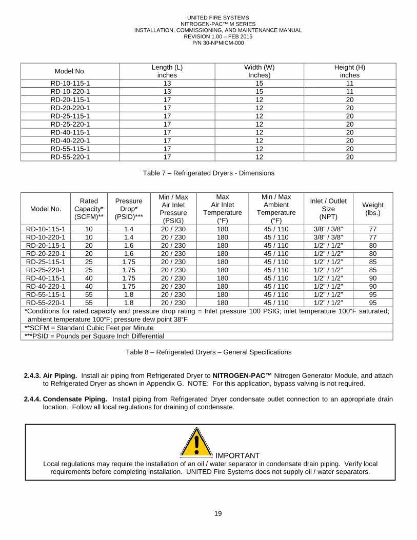
Table 8 – 2.4.3. Air Piping. Install air piping from Refrigerated Dryer to
to Refrigerated Dryer as shown in Appendix 2.4.4. Condensate Piping. Install piping from Refrigerated Dryer condensate outlet connection to an appropriate drain
location. Follow all local regulations for draining of condensate.
Local regulations may require the installation of an oil / water separator inrequirements before completing installation. UNITED Fire Systems does not supply oil / water separators.
UNITED FIRE SYSTEMS NITROGEN-PAC™ M SERIES
INSTALLATION, COMMISSIONING, AND MAINTENANCE MANUAL REVISION 1.00 – FEB 2015
P/N 30-NPMICM-000
19
Length (L) inches
Width (W) Inches)
13 15 13 15 17 12 17 12 17 12 17 12 17 12 17 12 17 12 17 12
Table 7 – Refrigerated Dryers - Dimensions
Min / Max Air Inlet
Pressure (PSIG)
Max Air Inlet
Temperature (°F)
Min / Max Ambient
Temperature (°F)
Inlet / Outlet
20 / 230 180 45 / 110 20 / 230 180 45 / 110 20 / 230 180 45 / 110 20 / 230 180 45 / 110 20 / 230 180 45 / 110 20 / 230 180 45 / 110 20 / 230 180 45 / 110 20 / 230 180 45 / 110 20 / 230 180 45 / 110 20 / 230 180 45 / 110
*Conditions for rated capacity and pressure drop rating = Inlet pressure 100 PSIG; inlet temperature 100F; pressure dew point 38°F
***PSID = Pounds per Square Inch Differential
Refrigerated Dryers – General Specifications
air piping from Refrigerated Dryer to NITROGEN-PAC™ Nitrogen Generator Module, Appendix G. NOTE: For this application, bypass valving is not required.
Install piping from Refrigerated Dryer condensate outlet connection to an appropriate drain location. Follow all local regulations for draining of condensate.
IMPORTANT Local regulations may require the installation of an oil / water separator in condensate drain piping. Verify local
requirements before completing installation. UNITED Fire Systems does not supply oil / water separators.
Height (H) inches
11 11 20 20 20 20 20 20 20 20
Inlet / Outlet Size
(NPT)
Weight (lbs.)
3/8” / 3/8” 77 3/8” / 3/8” 77 1/2” / 1/2” 80 1/2” / 1/2” 80 1/2” / 1/2” 85 1/2” / 1/2” 85 1/2” / 1/2” 90 1/2” / 1/2” 90 1/2” / 1/2” 95 1/2” / 1/2” 95
*Conditions for rated capacity and pressure drop rating = Inlet pressure 100 PSIG; inlet temperature 100°F saturated;
Nitrogen Generator Module, and attach NOTE: For this application, bypass valving is not required.
Install piping from Refrigerated Dryer condensate outlet connection to an appropriate drain
condensate drain piping. Verify local requirements before completing installation. UNITED Fire Systems does not supply oil / water separators.
INSTALLATION, COMMISSIONING, AND MAINTENANCE MANUAL
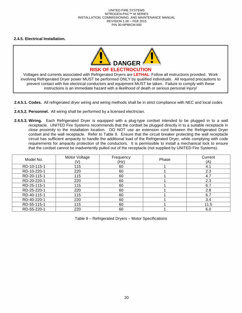
2.4.5. Electrical Installation. 2.4.5.1. Codes. All refrigerated dryer wiring and wiring methods shall be in . 2.4.5.2. Personnel. All wiring shall be performed by a licensed electrician. 2.4.5.3. Wiring. Each Refrigerated Dryer is equipped with a plug
receptacle. UNITED Fire Systems recommends that the cordset be plugged directly in to a suitable receptacle in close proximity to the installation location. cordset and the wall receptacle. Refer to circuit has sufficient ampacity to handle the additional load of the Refrigeraterequirements for ampacity protection of the conductors. It is permissible to install a mechanical lock to ensure that the cordset cannot be inadvertently pulled out of the receptacle (not supplied by UNITED Fire Systems)
Model No. Motor Voltage
(V) RD-10-115-1 115 RD-10-220-1 220 RD-20-115-1 115 RD-20-220-1 220 RD-25-115-1 115 RD-25-220-1 220 RD-40-115-1 115 RD-40-220-1 220 RD-55-115-1 115 RD-55-220-1 220
Table 9 –
RISK OF ELECTROCUTIONVoltages and currents associated with Refrigerated Dryers are
involving Refrigerated Dryer power MUST be performed ONLY by qualified individuals. All required precautions to prevent contact with live electrical conductors and equipment MUST be taken. Failure to comply with these
instructions is an immediate hazard with a likelihood of death or serious personal injury
UNITED FIRE SYSTEMS NITROGEN-PAC™ M SERIES
INSTALLATION, COMMISSIONING, AND MAINTENANCE MANUAL REVISION 1.00 – FEB 2015
P/N 30-NPMICM-000
20
wiring and wiring methods shall be in strict compliance with NEC and local codes
All wiring shall be performed by a licensed electrician.
Each Refrigerated Dryer is equipped with a plug-type cordset intended to be plugged in to a wall receptacle. UNITED Fire Systems recommends that the cordset be plugged directly in to a suitable receptacle in close proximity to the installation location. DO NOT use an extension cord between the Refrigerated Dryer cordset and the wall receptacle. Refer to Table 9. Ensure that the circuit breaker protecting the wall receptacle circuit has sufficient ampacity to handle the additional load of the Refrigerated Dryer, while complying with code requirements for ampacity protection of the conductors. It is permissible to install a mechanical lock to ensure that the cordset cannot be inadvertently pulled out of the receptacle (not supplied by UNITED Fire Systems)
Frequency (Hz) Phase
60 1 60 1 60 1 60 1 60 1 60 1 60 1 60 1 60 1 60 1
– Refrigerated Dryers – Motor Specifications
DANGER RISK OF ELECTROCUTION
Voltages and currents associated with Refrigerated Dryers are LETHAL . Follow all instructions provided. Work involving Refrigerated Dryer power MUST be performed ONLY by qualified individuals. All required precautions to
electrical conductors and equipment MUST be taken. Failure to comply with these an immediate hazard with a likelihood of death or serious personal injury
strict compliance with NEC and local codes
type cordset intended to be plugged in to a wall receptacle. UNITED Fire Systems recommends that the cordset be plugged directly in to a suitable receptacle in
DO NOT use an extension cord between the Refrigerated Dryer Ensure that the circuit breaker protecting the wall receptacle
d Dryer, while complying with code requirements for ampacity protection of the conductors. It is permissible to install a mechanical lock to ensure that the cordset cannot be inadvertently pulled out of the receptacle (not supplied by UNITED Fire Systems).
Current (A) 4.1 2.3 4.7 2.3 6.7 2.8 6.7 3.4 11.5 6.0
. Follow all instructions provided. Work involving Refrigerated Dryer power MUST be performed ONLY by qualified individuals. All required precautions to
electrical conductors and equipment MUST be taken. Failure to comply with these an immediate hazard with a likelihood of death or serious personal injury!
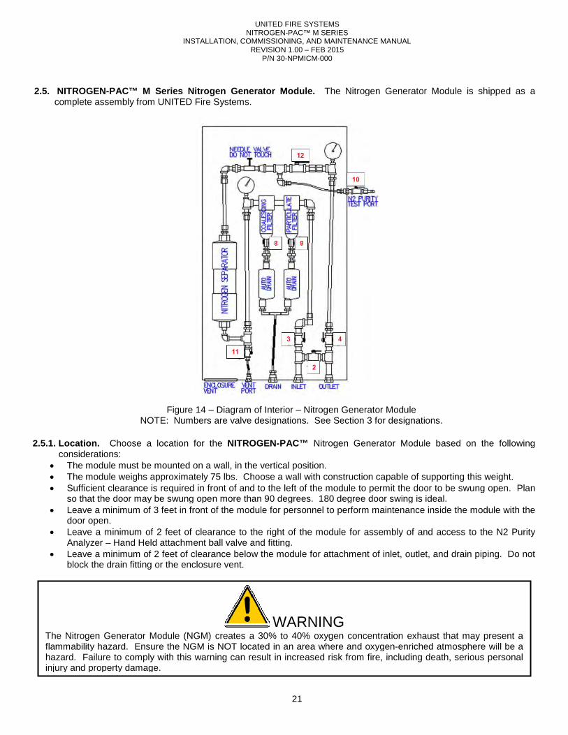
INSTALLATION, COMMISSIONING, AND MAINTENANCE MANUAL
2.5. NITROGEN-PAC™ M Series Nitrogen complete assembly from UNITED Fire Systems.
2.5.1. Location. Choose a location for the considerations:
• The module must be mounted on a wall, in the vertical position.• The module weighs approximately 75 lbs.• Sufficient clearance is required in front of
so that the door may be swung open more than 90 degrees. 180 degree door swing is ideal.• Leave a minimum of 3 feet in front of the module for person
door open. • Leave a minimum of 2 feet of clearance to the right of the module for assembly of and access to the N2 P
Analyzer – Hand Held attachment ball valve and fitting.• Leave a minimum of 2 feet of clearance below the module for attachment of inlet, outlet, and drain piping
block the drain fitting or the enclosure vent.
Figure 14 –NOTE: Numbers are valve designations. See
The Nitrogen Generator Module (NGM) creates a 30% to 40% oxygen concentration exhaust that may present a flammability hazard. Ensure the NGM is NOT located in an area where and oxygenhazard. Failure to comply with this warning can result in increased risk from fire, including death, serious personal injury and property damage.
UNITED FIRE SYSTEMS NITROGEN-PAC™ M SERIES
INSTALLATION, COMMISSIONING, AND MAINTENANCE MANUAL REVISION 1.00 – FEB 2015
P/N 30-NPMICM-000
21
Nitrogen Generator Module. The Nitrogen Generator Module is shipped as a
from UNITED Fire Systems.
Choose a location for the NITROGEN-PAC™ Nitrogen Generator Module based on the following
The module must be mounted on a wall, in the vertical position. 75 lbs. Choose a wall with construction capable of supporting this weight.
clearance is required in front of and to the left of the module to permit the door to be swung open. Plan so that the door may be swung open more than 90 degrees. 180 degree door swing is ideal.Leave a minimum of 3 feet in front of the module for personnel to perform maintenance inside the module with the
Leave a minimum of 2 feet of clearance to the right of the module for assembly of and access to the N2 PHand Held attachment ball valve and fitting.
of clearance below the module for attachment of inlet, outlet, and drain pipingblock the drain fitting or the enclosure vent.
– Diagram of Interior – Nitrogen Generator Module NOTE: Numbers are valve designations. See Section 3 for designations.
WARNING The Nitrogen Generator Module (NGM) creates a 30% to 40% oxygen concentration exhaust that may present a flammability hazard. Ensure the NGM is NOT located in an area where and oxygen-enriched atmosphere will be a hazard. Failure to comply with this warning can result in increased risk from fire, including death, serious personal
The Nitrogen Generator Module is shipped as a
Module based on the following
Choose a wall with construction capable of supporting this weight. the module to permit the door to be swung open. Plan
so that the door may be swung open more than 90 degrees. 180 degree door swing is ideal. nel to perform maintenance inside the module with the
Leave a minimum of 2 feet of clearance to the right of the module for assembly of and access to the N2 Purity
of clearance below the module for attachment of inlet, outlet, and drain piping. Do not
for designations.
The Nitrogen Generator Module (NGM) creates a 30% to 40% oxygen concentration exhaust that may present a enriched atmosphere will be a
hazard. Failure to comply with this warning can result in increased risk from fire, including death, serious personal
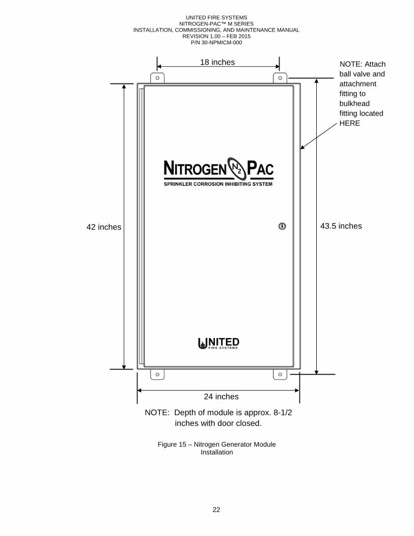
UNITED FIRE SYSTEMS NITROGEN-PAC™ M SERIES
INSTALLATION, COMMISSIONING, AND MAINTENANCE MANUAL REVISION 1.00 – FEB 2015
P/N 30-NPMICM-000
22
Figure 15 – Nitrogen Generator Module Installation
18 inches
43.5 inches 42 inches
24 inches
NOTE: Depth of module is approx. 8-1/2 inches with door closed.
NOTE: Attach ball valve and attachment fitting to bulkhead fitting located HERE
INSTALLATION, COMMISSIONING, AND MAINTENANCE MANUAL
2.5.2. Mounting. Mount the NITROGEN-PAC™
module must be mounted vertically as shown. standard practice and appropriate fasteners.
2.5.3. Connections and Openings. Refer to 2.5.3.1. Enclosure Vent. The purpose of the Enclosure Vent is to allow oxygen
exit the enclosure. Leave the Enclosure Vent clear. 2.5.3.2. Vent Port. The Vent Port is used when it is necessary to bleed pressure from the piping in the Nitrogen
Generator Module for maintenance. At installation, remove the plastic plug from the Vent Port and discard. Make no other connection to the Vent Port.
2.5.3.3. Drain. The Drain port is internally connected to the Auto Drains on the filters. Occasionally, water
removed by the Refrigerated Dryer may accumulate and be released by the Auto Drains. At installation, remove the plastic plug from the Drain port and discard. The Drain port may be left unconnected, or may be connected via tubing to an appropriate drain location. The Drain port is 1/2 inch NPT female.
2.5.3.4. Inlet. At installation, remove the plastic plug from the Inlet port and discard. Attach piping from Refrigerated
Dryer to Inlet port. The Inlet port is 1/2 inch NPT female. Use 1/2 inch blthreaded black steel fittings minimum Class 150.
2.5.3.5. Outlet. At installation, remove the plastic plug from the Outlet port and discard. Attach piping from Outlet of
Nitrogen Generator Module to Inlet of Nitrogen Receiver 1/2 inch black steel pipe minimum Sch. 40 and threaded black steel fittings minimum Class 150.
2.5.3.6. N2 Purity Analyzer Connection.
of module. Locate ball valve and module. Remove the plastic plug from the N2attachment fitting to connection point.
2.6. Nitrogen Receiver Assembly. The Nitrogen Receiver Assembly is shipped as a complete assembly from
UNITED Fire Systems.
Model No. Capacity (Gallons)
Inlet Size(NPT)
NR-30 30 1/2” NR-60 60 3/4” NR-80 80 3/4”
Table
Adequate ventilation is important for the Nitrogen Generator Module (NGM). While natural ventilation or existing openings may be adequate, consideration should be given to in a closet or other small space. A louvered door or 1Check with the owner and local codes before modifying any door
UNITED FIRE SYSTEMS NITROGEN-PAC™ M SERIES
INSTALLATION, COMMISSIONING, AND MAINTENANCE MANUAL REVISION 1.00 – FEB 2015
P/N 30-NPMICM-000
23
PAC™ Nitrogen Generator Module to a wall as shown in module must be mounted vertically as shown. The weight of the Nitrogen Generator Modulestandard practice and appropriate fasteners.
Refer to Figure 14.
The purpose of the Enclosure Vent is to allow oxygen-rich gas from the separator membrane to exit the enclosure. Leave the Enclosure Vent clear.
The Vent Port is used when it is necessary to bleed pressure from the piping in the Nitrogen enerator Module for maintenance. At installation, remove the plastic plug from the Vent Port and discard.
Make no other connection to the Vent Port.
The Drain port is internally connected to the Auto Drains on the filters. Occasionally, water removed by the Refrigerated Dryer may accumulate and be released by the Auto Drains. At installation, remove the plastic plug from the Drain port and discard. The Drain port may be left unconnected, or may be connected
riate drain location. The Drain port is 1/2 inch NPT female.
At installation, remove the plastic plug from the Inlet port and discard. Attach piping from Refrigerated Dryer to Inlet port. The Inlet port is 1/2 inch NPT female. Use 1/2 inch black steel pipe minimum Sch. 40 and threaded black steel fittings minimum Class 150.
At installation, remove the plastic plug from the Outlet port and discard. Attach piping from Outlet of Nitrogen Generator Module to Inlet of Nitrogen Receiver Assembly. The Outlet port is 1/2 inch NPT female. Use 1/2 inch black steel pipe minimum Sch. 40 and threaded black steel fittings minimum Class 150.
Refer to Figure 15 for location of N2 Purity Analyzer Connection on right side ball valve and attachment fitting for N2 Purity Analyzer Connection packed within interior of
module. Remove the plastic plug from the N2 purity analyzer connection and discarattachment fitting to connection point.
The Nitrogen Receiver Assembly is shipped as a complete assembly from
Inlet Size
Outlet Size (NPT)
Pressure Gage Scale
(PSIG)
Max Pressure (PSIG)
Safety Relief Valve
(PSIG)1/2” 0 - 200 200 3/4” 0 - 200 200 3/4” 0 - 200 200
Table 10 – Nitrogen Receivers - Specifications
IMPORTANT Adequate ventilation is important for the Nitrogen Generator Module (NGM). While natural ventilation or existing openings may be adequate, consideration should be given to providing additional ventilation when locating the NGM in a closet or other small space. A louvered door or 1-1/2 inch gap between the door and floor should be sufficient. Check with the owner and local codes before modifying any door.
wall as shown in Figure 15. The Module is 75 lbs. Use good
rich gas from the separator membrane to
The Vent Port is used when it is necessary to bleed pressure from the piping in the Nitrogen enerator Module for maintenance. At installation, remove the plastic plug from the Vent Port and discard.
The Drain port is internally connected to the Auto Drains on the filters. Occasionally, water that is not removed by the Refrigerated Dryer may accumulate and be released by the Auto Drains. At installation, remove the plastic plug from the Drain port and discard. The Drain port may be left unconnected, or may be connected
At installation, remove the plastic plug from the Inlet port and discard. Attach piping from Refrigerated ack steel pipe minimum Sch. 40 and
At installation, remove the plastic plug from the Outlet port and discard. Attach piping from Outlet of Assembly. The Outlet port is 1/2 inch NPT female. Use
1/2 inch black steel pipe minimum Sch. 40 and threaded black steel fittings minimum Class 150.
for location of N2 Purity Analyzer Connection on right side Analyzer Connection packed within interior of
purity analyzer connection and discard. Attach ball valve and
The Nitrogen Receiver Assembly is shipped as a complete assembly from
Safety Relief Valve Setting
(PSIG)
Weight (lbs.)
175 79 175 151 175 225
Adequate ventilation is important for the Nitrogen Generator Module (NGM). While natural ventilation or existing providing additional ventilation when locating the NGM
1/2 inch gap between the door and floor should be sufficient.
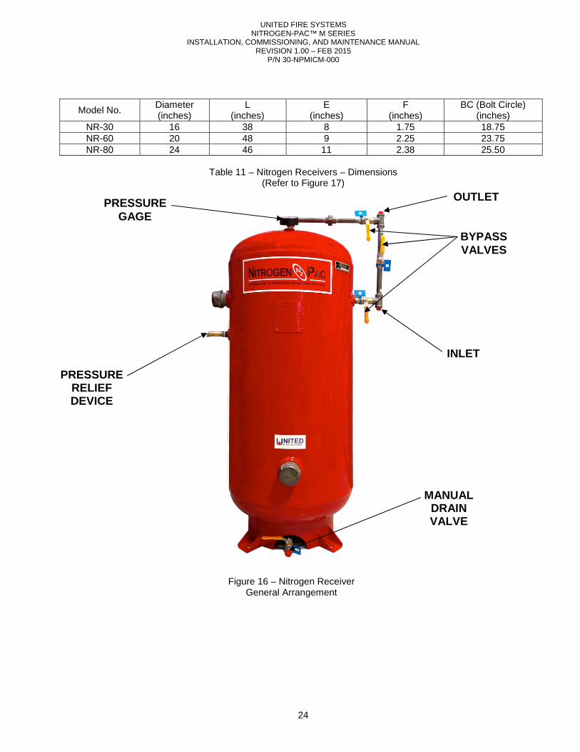
UNITED FIRE SYSTEMS NITROGEN-PAC™ M SERIES
INSTALLATION, COMMISSIONING, AND MAINTENANCE MANUAL REVISION 1.00 – FEB 2015
P/N 30-NPMICM-000
24
Model No. Diameter (inches)
L (inches)
E (inches)
F (inches)
BC (Bolt Circle) (inches)
NR-30 16 38 8 1.75 18.75 NR-60 20 48 9 2.25 23.75 NR-80 24 46 11 2.38 25.50
Table 11 – Nitrogen Receivers – Dimensions
(Refer to Figure 17)
OUTLET
BYPASS VALVES
INLET
PRESSURE GAGE
MANUAL DRAIN VALVE
PRESSURE RELIEF DEVICE
Figure 16 – Nitrogen Receiver General Arrangement
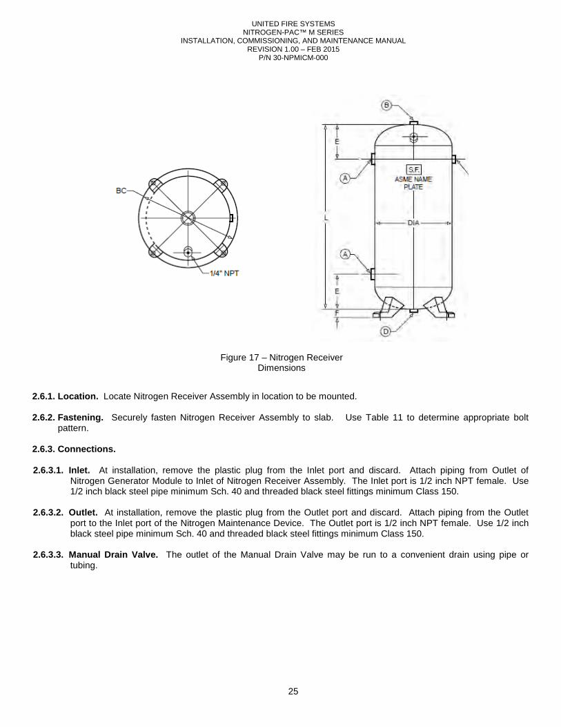
UNITED FIRE SYSTEMS NITROGEN-PAC™ M SERIES
INSTALLATION, COMMISSIONING, AND MAINTENANCE MANUAL REVISION 1.00 – FEB 2015
P/N 30-NPMICM-000
25
2.6.1. Location. Locate Nitrogen Receiver Assembly in location to be mounted. 2.6.2. Fastening. Securely fasten Nitrogen Receiver Assembly to slab. Use Table 11 to determine appropriate bolt
pattern. 2.6.3. Connections. 2.6.3.1. Inlet. At installation, remove the plastic plug from the Inlet port and discard. Attach piping from Outlet of
Nitrogen Generator Module to Inlet of Nitrogen Receiver Assembly. The Inlet port is 1/2 inch NPT female. Use 1/2 inch black steel pipe minimum Sch. 40 and threaded black steel fittings minimum Class 150.
2.6.3.2. Outlet. At installation, remove the plastic plug from the Outlet port and discard. Attach piping from the Outlet
port to the Inlet port of the Nitrogen Maintenance Device. The Outlet port is 1/2 inch NPT female. Use 1/2 inch black steel pipe minimum Sch. 40 and threaded black steel fittings minimum Class 150.
2.6.3.3. Manual Drain Valve. The outlet of the Manual Drain Valve may be run to a convenient drain using pipe or
tubing.
Figure 17 – Nitrogen Receiver Dimensions
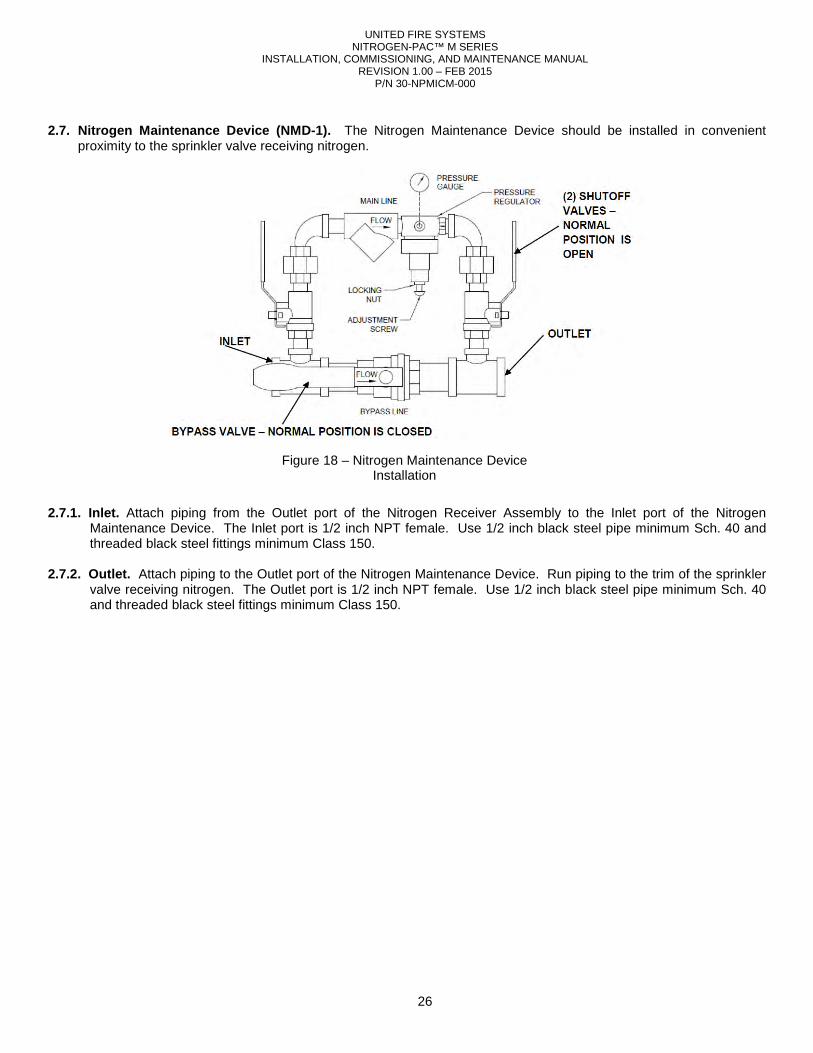
UNITED FIRE SYSTEMS NITROGEN-PAC™ M SERIES
INSTALLATION, COMMISSIONING, AND MAINTENANCE MANUAL REVISION 1.00 – FEB 2015
P/N 30-NPMICM-000
26
2.7. Nitrogen Maintenance Device (NMD-1). The Nitrogen Maintenance Device should be installed in convenient
proximity to the sprinkler valve receiving nitrogen. 2.7.1. Inlet. Attach piping from the Outlet port of the Nitrogen Receiver Assembly to the Inlet port of the Nitrogen
Maintenance Device. The Inlet port is 1/2 inch NPT female. Use 1/2 inch black steel pipe minimum Sch. 40 and threaded black steel fittings minimum Class 150.
2.7.2. Outlet. Attach piping to the Outlet port of the Nitrogen Maintenance Device. Run piping to the trim of the sprinkler
valve receiving nitrogen. The Outlet port is 1/2 inch NPT female. Use 1/2 inch black steel pipe minimum Sch. 40 and threaded black steel fittings minimum Class 150.
Figure 18 – Nitrogen Maintenance Device Installation
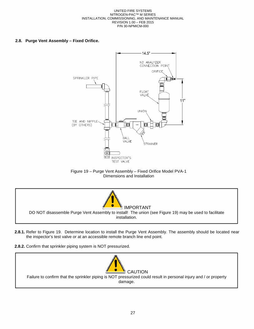
INSTALLATION, COMMISSIONING, AND MAINTENANCE MANUAL
2.8. Purge Vent Assembly – Fixed Orifice
2.8.1. Refer to Figure 19. Determine location to install the
the inspector’s test valve or at an accessible remote branch line end point. 2.8.2. Confirm that sprinkler piping system is
Figure 19 – Purge Vent Assembly
DO NOT disassemble Purge Vent Assembly to install! The union (see
Failure to confirm that the sprinkler piping is NOT pressurized could result in personal injury and / or property
UNITED FIRE SYSTEMS NITROGEN-PAC™ M SERIES
INSTALLATION, COMMISSIONING, AND MAINTENANCE MANUAL REVISION 1.00 – FEB 2015
P/N 30-NPMICM-000
27
Fixed Orifice .
Determine location to install the Purge Vent Assembly. The assemblyor at an accessible remote branch line end point.
Confirm that sprinkler piping system is NOT pressurized.
Purge Vent Assembly – Fixed Orifice Model PVA-1 Dimensions and Installation
IMPORTANT DO NOT disassemble Purge Vent Assembly to install! The union (see Figure 19) may be used to facilitate
installation.
CAUTION confirm that the sprinkler piping is NOT pressurized could result in personal injury and / or property
damage.
he assembly should be located near
may be used to facilitate
confirm that the sprinkler piping is NOT pressurized could result in personal injury and / or property
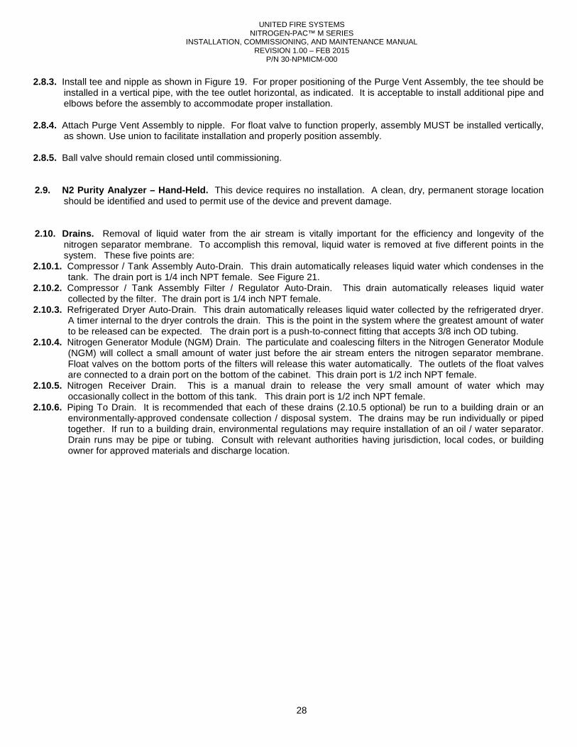
UNITED FIRE SYSTEMS NITROGEN-PAC™ M SERIES
INSTALLATION, COMMISSIONING, AND MAINTENANCE MANUAL REVISION 1.00 – FEB 2015
P/N 30-NPMICM-000
28
2.8.3. Install tee and nipple as shown in Figure 19. For proper positioning of the Purge Vent Assembly, the tee should be installed in a vertical pipe, with the tee outlet horizontal, as indicated. It is acceptable to install additional pipe and elbows before the assembly to accommodate proper installation.
2.8.4. Attach Purge Vent Assembly to nipple. For float valve to function properly, assembly MUST be installed vertically,
as shown. Use union to facilitate installation and properly position assembly. 2.8.5. Ball valve should remain closed until commissioning. 2.9. N2 Purity Analyzer – Hand-Held. This device requires no installation. A clean, dry, permanent storage location
should be identified and used to permit use of the device and prevent damage. 2.10. Drains. Removal of liquid water from the air stream is vitally important for the efficiency and longevity of the
nitrogen separator membrane. To accomplish this removal, liquid water is removed at five different points in the system. These five points are:
2.10.1. Compressor / Tank Assembly Auto-Drain. This drain automatically releases liquid water which condenses in the tank. The drain port is 1/4 inch NPT female. See Figure 21.
2.10.2. Compressor / Tank Assembly Filter / Regulator Auto-Drain. This drain automatically releases liquid water collected by the filter. The drain port is 1/4 inch NPT female.
2.10.3. Refrigerated Dryer Auto-Drain. This drain automatically releases liquid water collected by the refrigerated dryer. A timer internal to the dryer controls the drain. This is the point in the system where the greatest amount of water to be released can be expected. The drain port is a push-to-connect fitting that accepts 3/8 inch OD tubing.
2.10.4. Nitrogen Generator Module (NGM) Drain. The particulate and coalescing filters in the Nitrogen Generator Module (NGM) will collect a small amount of water just before the air stream enters the nitrogen separator membrane. Float valves on the bottom ports of the filters will release this water automatically. The outlets of the float valves are connected to a drain port on the bottom of the cabinet. This drain port is 1/2 inch NPT female.
2.10.5. Nitrogen Receiver Drain. This is a manual drain to release the very small amount of water which may occasionally collect in the bottom of this tank. This drain port is 1/2 inch NPT female.
2.10.6. Piping To Drain. It is recommended that each of these drains (2.10.5 optional) be run to a building drain or an environmentally-approved condensate collection / disposal system. The drains may be run individually or piped together. If run to a building drain, environmental regulations may require installation of an oil / water separator. Drain runs may be pipe or tubing. Consult with relevant authorities having jurisdiction, local codes, or building owner for approved materials and discharge location.
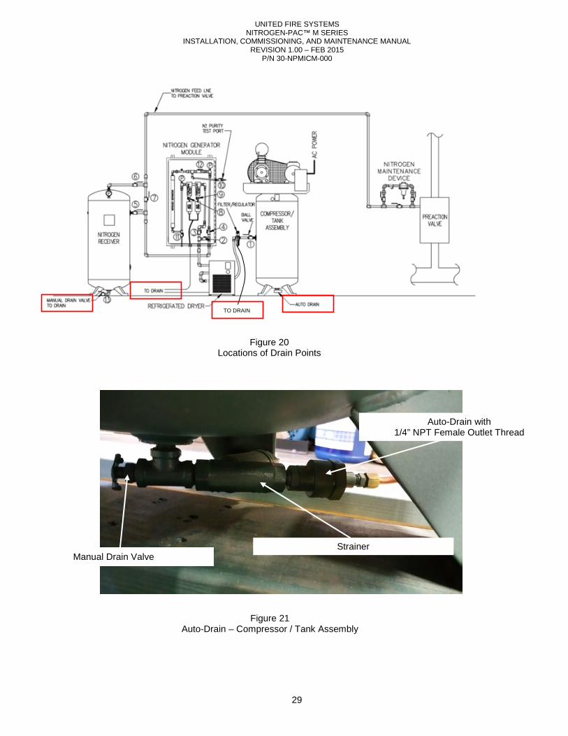
UNITED FIRE SYSTEMS NITROGEN-PAC™ M SERIES
INSTALLATION, COMMISSIONING, AND MAINTENANCE MANUAL REVISION 1.00 – FEB 2015
P/N 30-NPMICM-000
29
TO DRAIN
Figure 20 Locations of Drain Points
Figure 21 Auto-Drain – Compressor / Tank Assembly
Auto-Drain with 1/4” NPT Female Outlet Thread
Manual Drain Valve Strainer
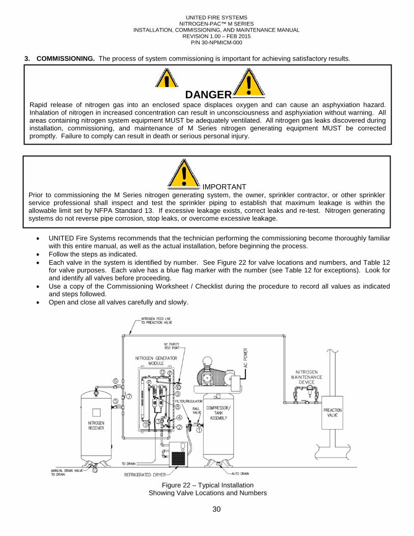
INSTALLATION, COMMISSIONING, AND MAINTENANCE MANUAL
3. COMMISSIONING. The process of system commissioning is important for achieving satisfactory results.
• UNITED Fire Systems recommends that the technician performing the commissioning become thoroughly fawith this entire manual, as well as the actual installation, before beginning the process.
• Follow the steps as indicated. • Each valve in the system is identified by number. See
for valve purposes. Each valve has a blue flag marker with the number (seeand identify all valves before proceeding.
• Use a copy of the Commissioning Worksheet / Checklist during the procedure to record all values as indicated and steps followed.
• Open and close all valves carefully
Showing Valve Locations and Numbers
Rapid release of nitrogen gas into an enclosed space displaces oxygen and Inhalation of nitrogen in increased concentration can result in unconsciousness and asphyxiation without warning. All areas containing nitrogen system equipment MUST be adequately ventilated. All nitrogen gas leaks discinstallation, commissioning, and maintenance of M Series nitrogen generating equipment MUST be corrected promptly. Failure to comply can result in death or serious personal injury.
Prior to commissioning the M Series nitrogen generating system, the owner, sprinkler contractor, or other sprinkler service professional shall inspect and test the sprinkler piping to establish that maximum leakage is within the allowable limit set by NFPA Standard 13. If excessive lsystems do not reverse pipe corrosion, stop leaks, or overcome excessive leakage.
UNITED FIRE SYSTEMS NITROGEN-PAC™ M SERIES
INSTALLATION, COMMISSIONING, AND MAINTENANCE MANUAL REVISION 1.00 – FEB 2015
P/N 30-NPMICM-000
30
The process of system commissioning is important for achieving satisfactory results.
UNITED Fire Systems recommends that the technician performing the commissioning become thoroughly fawith this entire manual, as well as the actual installation, before beginning the process.
Each valve in the system is identified by number. See Figure 22 for valve locations and numbers, and . Each valve has a blue flag marker with the number (see Table 12
and identify all valves before proceeding. Use a copy of the Commissioning Worksheet / Checklist during the procedure to record all values as indicated
and slowly.
Figure 22 – Typical Installation Showing Valve Locations and Numbers
DANGER Rapid release of nitrogen gas into an enclosed space displaces oxygen and can cause an asphyxiation hazard. Inhalation of nitrogen in increased concentration can result in unconsciousness and asphyxiation without warning. All areas containing nitrogen system equipment MUST be adequately ventilated. All nitrogen gas leaks discinstallation, commissioning, and maintenance of M Series nitrogen generating equipment MUST be corrected promptly. Failure to comply can result in death or serious personal injury.
IMPORTANT Series nitrogen generating system, the owner, sprinkler contractor, or other sprinkler
service professional shall inspect and test the sprinkler piping to establish that maximum leakage is within the allowable limit set by NFPA Standard 13. If excessive leakage exists, correct leaks and re-test. Nitrogen generating systems do not reverse pipe corrosion, stop leaks, or overcome excessive leakage.
The process of system commissioning is important for achieving satisfactory results.
UNITED Fire Systems recommends that the technician performing the commissioning become thoroughly familiar with this entire manual, as well as the actual installation, before beginning the process.
for valve locations and numbers, and Table 12 12 for exceptions). Look for
Use a copy of the Commissioning Worksheet / Checklist during the procedure to record all values as indicated
can cause an asphyxiation hazard. Inhalation of nitrogen in increased concentration can result in unconsciousness and asphyxiation without warning. All areas containing nitrogen system equipment MUST be adequately ventilated. All nitrogen gas leaks discovered during installation, commissioning, and maintenance of M Series nitrogen generating equipment MUST be corrected
Series nitrogen generating system, the owner, sprinkler contractor, or other sprinkler service professional shall inspect and test the sprinkler piping to establish that maximum leakage is within the
test. Nitrogen generating
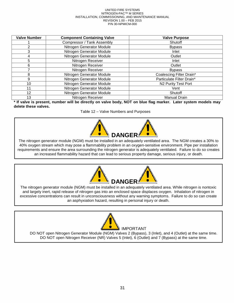
INSTALLATION, COMMISSIONING, AND MAINTENANCE MANUAL
Valve Number Component Containing Valve
1 Compressor / Tank Assembly2 Nitrogen Generator Module3 Nitrogen Generator Module4 Nitrogen Generator Module5 Nitrogen Receiver6 Nitrogen Receiver7 Nitrogen Receiver8 Nitrogen Generator Module9 Nitrogen Generator Module10 Nitrogen Generator Module11 Nitrogen Generator Module12 Nitrogen Generator Module13 Nitrogen Receiver
* If valve is present, number will be directly on valve body, NOT on blue flag marker. Later system models may delete these valves.
DO NOT open Nitrogen Generator Module (NGM) Valves 2 (Bypass), 3 (Inlet), and 4 (Outlet) at the same time.DO NOT open Nitrogen Receiver (NR) Valves 5 (Inlet)
The nitrogen generator module (NGM) mustand largely inert, rapid release of nitrogen gas into an enclosed space displaces oxygen
excessive concentrations can result in unconsciousness without any warning symptoms.an asphyxiation hazard, resulting in personal injury or death.
The nitrogen generator module (NGM) must be installed in an adequately ventilated area. 40% oxygen stream which may pose a flammability problem in an oxygen
requirements and ensure the area surrounding the nitrogen generator is adequately ventilated.an increased flammability hazard that can lead to serious property damage, serious injury, or death.
Table
UNITED FIRE SYSTEMS NITROGEN-PAC™ M SERIES
INSTALLATION, COMMISSIONING, AND MAINTENANCE MANUAL REVISION 1.00 – FEB 2015
P/N 30-NPMICM-000
31
Component Containing Valve Valve PurposeCompressor / Tank Assembly ShutoffNitrogen Generator Module BypassNitrogen Generator Module InletNitrogen Generator Module Outlet
Nitrogen Receiver InletNitrogen Receiver OutletNitrogen Receiver Bypass
Nitrogen Generator Module Coalescing Filter Drain*Nitrogen Generator Module Particulate Filter Drain*Nitrogen Generator Module N2 Purity Test PortNitrogen Generator Module VentNitrogen Generator Module Shutoff
Nitrogen Receiver Manual DrainIf valve is present, number will be directly on valve body, NOT on blue flag marker. Later system models may
IMPORTANT DO NOT open Nitrogen Generator Module (NGM) Valves 2 (Bypass), 3 (Inlet), and 4 (Outlet) at the same time.
DO NOT open Nitrogen Receiver (NR) Valves 5 (Inlet), 6 (Outlet) and 7 (Bypass) at the same time.
DANGER module (NGM) must be installed in an adequately ventilated area. While n
apid release of nitrogen gas into an enclosed space displaces oxygen. Inhalation of nitrogen in excessive concentrations can result in unconsciousness without any warning symptoms. Failure to do so can create
an asphyxiation hazard, resulting in personal injury or death.
DANGER The nitrogen generator module (NGM) must be installed in an adequately ventilated area. The40% oxygen stream which may pose a flammability problem in an oxygen-sensitive environment. Pipe per installation
requirements and ensure the area surrounding the nitrogen generator is adequately ventilated.ncreased flammability hazard that can lead to serious property damage, serious injury, or death.
Table 12 – Valve Numbers and Purposes
Valve Purpose Shutoff Bypass
Inlet Outlet Inlet
Outlet Bypass
Coalescing Filter Drain* Particulate Filter Drain*
N2 Purity Test Port Vent
Shutoff Manual Drain
If valve is present, number will be directly on valve body, NOT on blue flag marker. Later system models may
DO NOT open Nitrogen Generator Module (NGM) Valves 2 (Bypass), 3 (Inlet), and 4 (Outlet) at the same time. 7 (Bypass) at the same time.
While nitrogen is nontoxic Inhalation of nitrogen in
Failure to do so can create
The NGM creates a 30% to sensitive environment. Pipe per installation
requirements and ensure the area surrounding the nitrogen generator is adequately ventilated. Failure to do so creates ncreased flammability hazard that can lead to serious property damage, serious injury, or death.
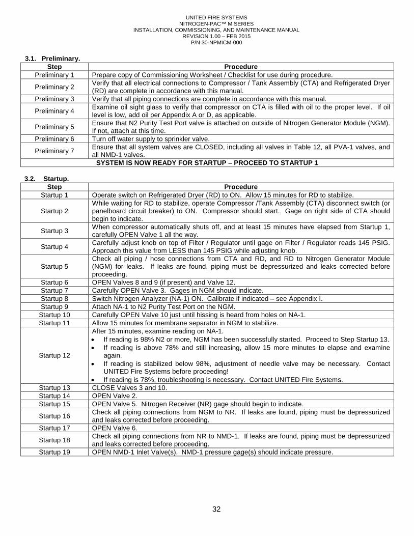
UNITED FIRE SYSTEMS NITROGEN-PAC™ M SERIES
INSTALLATION, COMMISSIONING, AND MAINTENANCE MANUAL REVISION 1.00 – FEB 2015
P/N 30-NPMICM-000
32
3.1. Preliminary. Step Procedure
Preliminary 1 Prepare copy of Commissioning Worksheet / Checklist for use during procedure.
Preliminary 2 Verify that all electrical connections to Compressor / Tank Assembly (CTA) and Refrigerated Dryer (RD) are complete in accordance with this manual.
Preliminary 3 Verify that all piping connections are complete in accordance with this manual.
Preliminary 4 Examine oil sight glass to verify that compressor on CTA is filled with oil to the proper level. If oil level is low, add oil per Appendix A or D, as applicable.
Preliminary 5 Ensure that N2 Purity Test Port valve is attached on outside of Nitrogen Generator Module (NGM). If not, attach at this time.
Preliminary 6 Turn off water supply to sprinkler valve.
Preliminary 7 Ensure that all system valves are CLOSED, including all valves in Table 12, all PVA-1 valves, and all NMD-1 valves.
SYSTEM IS NOW READY FOR STARTUP – PROCEED TO STARTUP 1 3.2. Startup.
Step Procedure Startup 1 Operate switch on Refrigerated Dryer (RD) to ON. Allow 15 minutes for RD to stabilize.
Startup 2 While waiting for RD to stabilize, operate Compressor /Tank Assembly (CTA) disconnect switch (or panelboard circuit breaker) to ON. Compressor should start. Gage on right side of CTA should begin to indicate.
Startup 3 When compressor automatically shuts off, and at least 15 minutes have elapsed from Startup 1, carefully OPEN Valve 1 all the way.
Startup 4 Carefully adjust knob on top of Filter / Regulator until gage on Filter / Regulator reads 145 PSIG. Approach this value from LESS than 145 PSIG while adjusting knob.
Startup 5 Check all piping / hose connections from CTA and RD, and RD to Nitrogen Generator Module (NGM) for leaks. If leaks are found, piping must be depressurized and leaks corrected before proceeding.
Startup 6 OPEN Valves 8 and 9 (if present) and Valve 12. Startup 7 Carefully OPEN Valve 3. Gages in NGM should indicate. Startup 8 Switch Nitrogen Analyzer (NA-1) ON. Calibrate if indicated – see Appendix I. Startup 9 Attach NA-1 to N2 Purity Test Port on the NGM. Startup 10 Carefully OPEN Valve 10 just until hissing is heard from holes on NA-1. Startup 11 Allow 15 minutes for membrane separator in NGM to stabilize.
Startup 12
After 15 minutes, examine reading on NA-1. • If reading is 98% N2 or more, NGM has been successfully started. Proceed to Step Startup 13. • If reading is above 78% and still increasing, allow 15 more minutes to elapse and examine
again. • If reading is stabilized below 98%, adjustment of needle valve may be necessary. Contact
UNITED Fire Systems before proceeding! • If reading is 78%, troubleshooting is necessary. Contact UNITED Fire Systems.
Startup 13 CLOSE Valves 3 and 10. Startup 14 OPEN Valve 2. Startup 15 OPEN Valve 5. Nitrogen Receiver (NR) gage should begin to indicate.
Startup 16 Check all piping connections from NGM to NR. If leaks are found, piping must be depressurized and leaks corrected before proceeding.
Startup 17 OPEN Valve 6.
Startup 18 Check all piping connections from NR to NMD-1. If leaks are found, piping must be depressurized and leaks corrected before proceeding.
Startup 19 OPEN NMD-1 Inlet Valve(s). NMD-1 pressure gage(s) should indicate pressure.
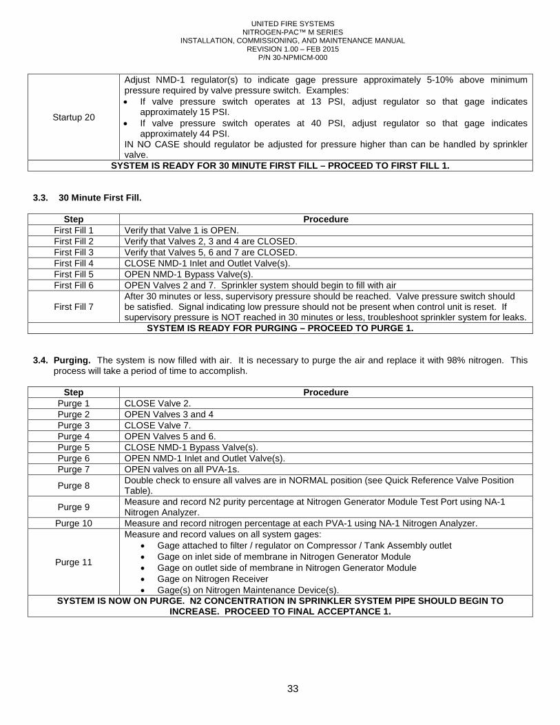
UNITED FIRE SYSTEMS NITROGEN-PAC™ M SERIES
INSTALLATION, COMMISSIONING, AND MAINTENANCE MANUAL REVISION 1.00 – FEB 2015
P/N 30-NPMICM-000
33
Startup 20
Adjust NMD-1 regulator(s) to indicate gage pressure approximately 5-10% above minimum pressure required by valve pressure switch. Examples: • If valve pressure switch operates at 13 PSI, adjust regulator so that gage indicates
approximately 15 PSI. • If valve pressure switch operates at 40 PSI, adjust regulator so that gage indicates
approximately 44 PSI. IN NO CASE should regulator be adjusted for pressure higher than can be handled by sprinkler valve.
SYSTEM IS READY FOR 30 MINUTE FIRST FILL – PROCEED TO FIRST FILL 1. 3.3. 30 Minute First Fill.
Step Procedure First Fill 1 Verify that Valve 1 is OPEN. First Fill 2 Verify that Valves 2, 3 and 4 are CLOSED. First Fill 3 Verify that Valves 5, 6 and 7 are CLOSED. First Fill 4 CLOSE NMD-1 Inlet and Outlet Valve(s). First Fill 5 OPEN NMD-1 Bypass Valve(s). First Fill 6 OPEN Valves 2 and 7. Sprinkler system should begin to fill with air
First Fill 7 After 30 minutes or less, supervisory pressure should be reached. Valve pressure switch should be satisfied. Signal indicating low pressure should not be present when control unit is reset. If supervisory pressure is NOT reached in 30 minutes or less, troubleshoot sprinkler system for leaks.
SYSTEM IS READY FOR PURGING – PROCEED TO PURGE 1. 3.4. Purging. The system is now filled with air. It is necessary to purge the air and replace it with 98% nitrogen. This
process will take a period of time to accomplish.
Step Procedure Purge 1 CLOSE Valve 2. Purge 2 OPEN Valves 3 and 4 Purge 3 CLOSE Valve 7. Purge 4 OPEN Valves 5 and 6. Purge 5 CLOSE NMD-1 Bypass Valve(s). Purge 6 OPEN NMD-1 Inlet and Outlet Valve(s). Purge 7 OPEN valves on all PVA-1s.
Purge 8 Double check to ensure all valves are in NORMAL position (see Quick Reference Valve Position Table).
Purge 9 Measure and record N2 purity percentage at Nitrogen Generator Module Test Port using NA-1 Nitrogen Analyzer.
Purge 10 Measure and record nitrogen percentage at each PVA-1 using NA-1 Nitrogen Analyzer.
Purge 11
Measure and record values on all system gages: • Gage attached to filter / regulator on Compressor / Tank Assembly outlet • Gage on inlet side of membrane in Nitrogen Generator Module • Gage on outlet side of membrane in Nitrogen Generator Module • Gage on Nitrogen Receiver • Gage(s) on Nitrogen Maintenance Device(s).
SYSTEM IS NOW ON PURGE. N2 CONCENTRATION IN SPRINKLER SYSTEM PIPE SHOULD BEGIN TO INCREASE. PROCEED TO FINAL ACCEPTANCE 1.
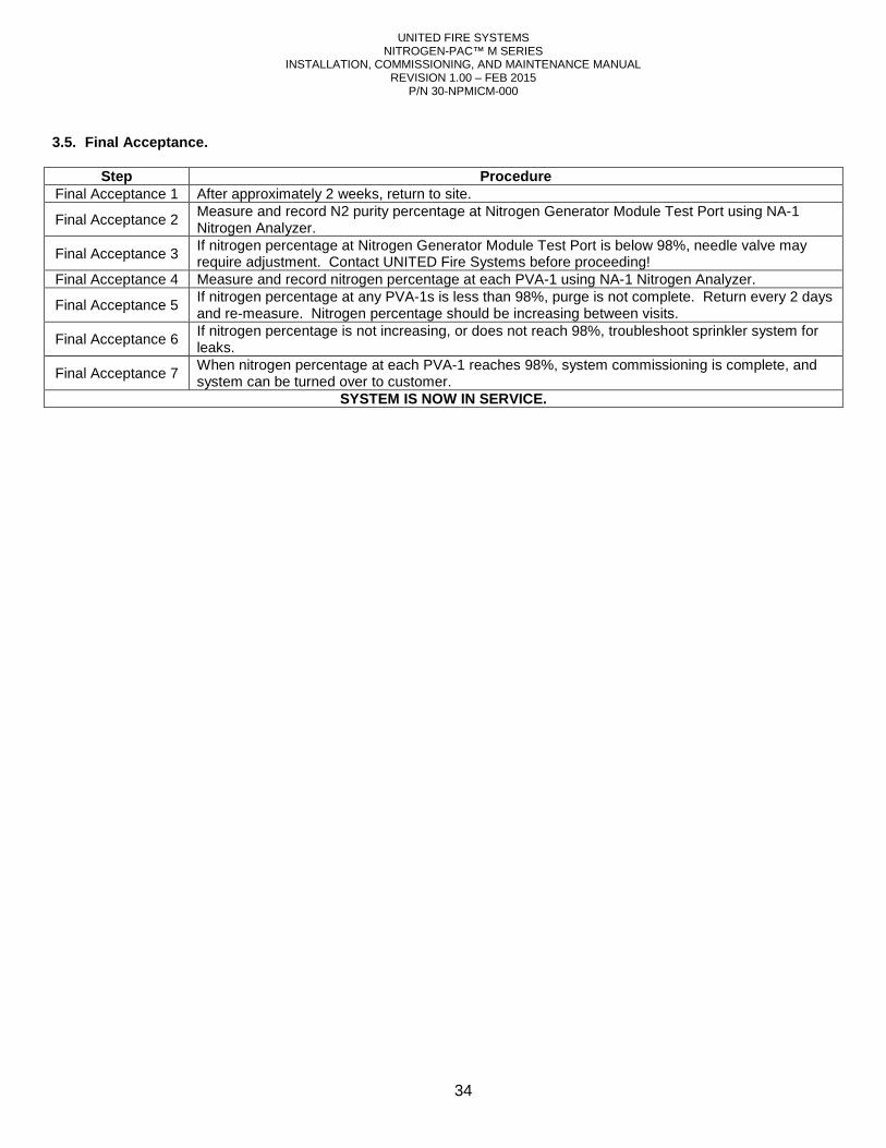
UNITED FIRE SYSTEMS NITROGEN-PAC™ M SERIES
INSTALLATION, COMMISSIONING, AND MAINTENANCE MANUAL REVISION 1.00 – FEB 2015
P/N 30-NPMICM-000
34
3.5. Final Acceptance.
Step Procedure Final Acceptance 1 After approximately 2 weeks, return to site.
Final Acceptance 2 Measure and record N2 purity percentage at Nitrogen Generator Module Test Port using NA-1 Nitrogen Analyzer.
Final Acceptance 3 If nitrogen percentage at Nitrogen Generator Module Test Port is below 98%, needle valve may require adjustment. Contact UNITED Fire Systems before proceeding!
Final Acceptance 4 Measure and record nitrogen percentage at each PVA-1 using NA-1 Nitrogen Analyzer.
Final Acceptance 5 If nitrogen percentage at any PVA-1s is less than 98%, purge is not complete. Return every 2 days and re-measure. Nitrogen percentage should be increasing between visits.
Final Acceptance 6 If nitrogen percentage is not increasing, or does not reach 98%, troubleshoot sprinkler system for leaks.
Final Acceptance 7 When nitrogen percentage at each PVA-1 reaches 98%, system commissioning is complete, and system can be turned over to customer.
SYSTEM IS NOW IN SERVICE.
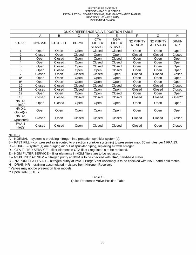
UNITED FIRE SYSTEMS NITROGEN-PAC™ M SERIES
INSTALLATION, COMMISSIONING, AND MAINTENANCE MANUAL REVISION 1.00 – FEB 2015
P/N 30-NPMICM-000
35
QUICK REFERENCE VALVE POSITION TABLE
A B C D E F G H
VALVE NORMAL FAST FILL PURGE CTA
FILTER SERVICE
NGM FILTER
SERVICE
N2 PURITY AT NGM
N2 PURITY AT PVA-1s
DRAIN NR
1 Open Open Open Closed Closed Open Open Open 2 Closed Open Closed Open Open Closed Closed Closed 3 Open Closed Open Open Closed Open Open Open 4 Open Closed Open Closed Closed Open Open Open 5 Open Closed Open Closed Closed Open Open Open 6 Open Closed Open Open Closed Open Open Open 7 Closed Open Closed Closed Open Closed Closed Closed 8* Open Open Open Open Open Open Open Open 9* Open Open Open Open Open Open Open Open 10 Closed Closed Closed Closed Closed Open Closed Closed 11 Closed Closed Closed Open Open Closed Closed Closed 12 Open Open Open Open Closed Open Open Open 13 Closed Closed Closed Closed Closed Closed Closed Open**
NMD-1 Inlet(s)
Open Closed Open Open Open Open Open Open
NMD-1 Outlet(s)
Open Open Open Open Open Open Open Open
NMD-1 Bypass(es)
Closed Open Closed Closed Closed Closed Closed Closed
PVA-1 Inlet(s)
Closed Closed Open Closed Closed Closed Open Closed
NOTES A – NORMAL – system is providing nitrogen into preaction sprinkler system(s). B – FAST FILL – compressed air is routed to preaction sprinkler system(s) to pressurize max. 30 minutes per NFPA 13. C – PURGE – system(s) are purging air out of sprinkler piping, replacing air with nitrogen. D – CTA FILTER SERVICE – filter element in CTA filter / regulator is to be replaced. E – NGM FILTER SERVICE – filter elements in NGM filters are to be replaced. F – N2 PURITY AT NGM – nitrogen purity at NGM is to be checked with NA-1 hand-held meter. G – N2 PURITY AT PVA-1 – nitrogen purity at PVA-1 Purge Vent Assembly is to be checked with NA-1 hand-held meter. H – DRAIN NR – draining accumulated moisture from Nitrogen Receiver. * Valves may not be present on later models. ** Open CAREFULLY.
Table 13 Quick-Reference Valve Position Table
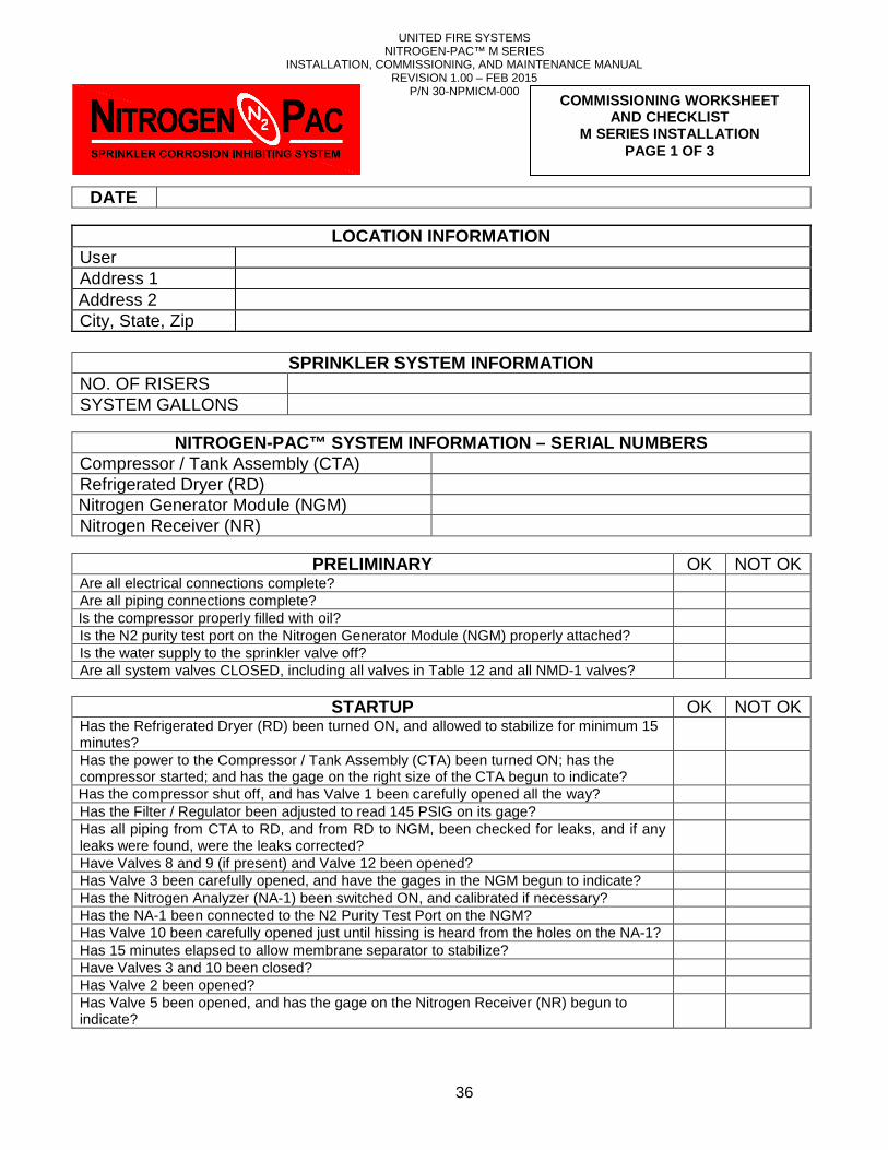
UNITED FIRE SYSTEMS NITROGEN-PAC™ M SERIES
INSTALLATION, COMMISSIONING, AND MAINTENANCE MANUAL REVISION 1.00 – FEB 2015
P/N 30-NPMICM-000
36
DATE
LOCATION INFORMATION User Address 1 Address 2 City, State, Zip
SPRINKLER SYSTEM INFORMATION
NO. OF RISERS SYSTEM GALLONS
NITROGEN-PAC™ SYSTEM INFORMATION – SERIAL NUMBERS
Compressor / Tank Assembly (CTA) Refrigerated Dryer (RD) Nitrogen Generator Module (NGM) Nitrogen Receiver (NR)
PRELIMINARY OK NOT OK
Are all electrical connections complete? Are all piping connections complete? Is the compressor properly filled with oil? Is the N2 purity test port on the Nitrogen Generator Module (NGM) properly attached? Is the water supply to the sprinkler valve off? Are all system valves CLOSED, including all valves in Table 12 and all NMD-1 valves?
STARTUP OK NOT OK
Has the Refrigerated Dryer (RD) been turned ON, and allowed to stabilize for minimum 15 minutes?
Has the power to the Compressor / Tank Assembly (CTA) been turned ON; has the compressor started; and has the gage on the right size of the CTA begun to indicate?
Has the compressor shut off, and has Valve 1 been carefully opened all the way? Has the Filter / Regulator been adjusted to read 145 PSIG on its gage? Has all piping from CTA to RD, and from RD to NGM, been checked for leaks, and if any leaks were found, were the leaks corrected?
Have Valves 8 and 9 (if present) and Valve 12 been opened? Has Valve 3 been carefully opened, and have the gages in the NGM begun to indicate? Has the Nitrogen Analyzer (NA-1) been switched ON, and calibrated if necessary? Has the NA-1 been connected to the N2 Purity Test Port on the NGM? Has Valve 10 been carefully opened just until hissing is heard from the holes on the NA-1? Has 15 minutes elapsed to allow membrane separator to stabilize? Have Valves 3 and 10 been closed? Has Valve 2 been opened? Has Valve 5 been opened, and has the gage on the Nitrogen Receiver (NR) begun to indicate?
COMMISSIONING WORKSHEET AND CHECKLIST
M SERIES INSTALLATION PAGE 1 OF 3
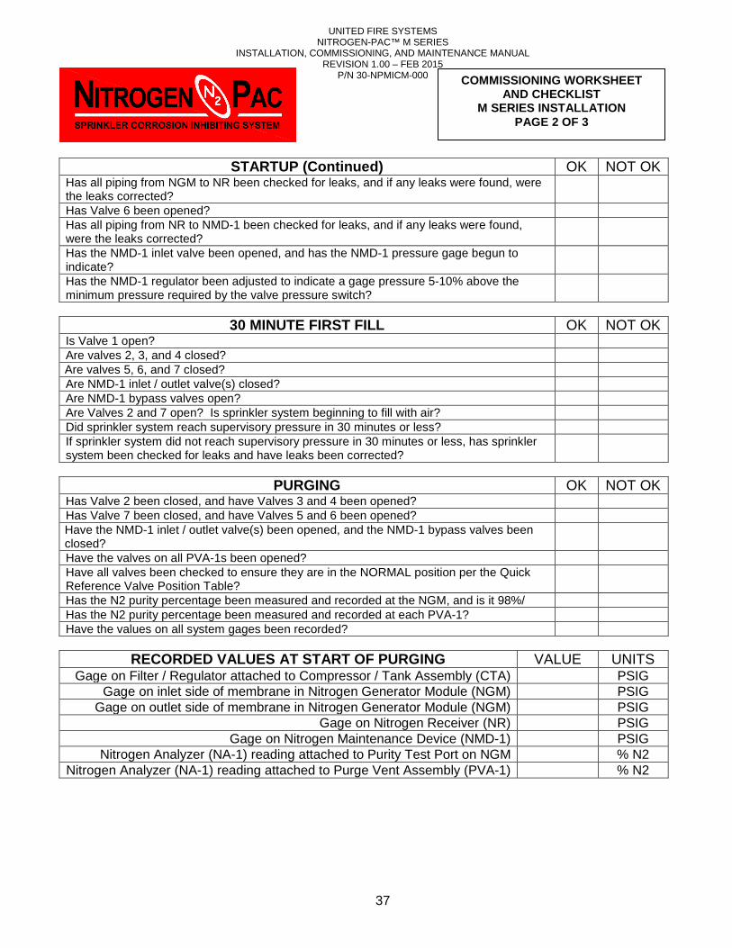
UNITED FIRE SYSTEMS NITROGEN-PAC™ M SERIES
INSTALLATION, COMMISSIONING, AND MAINTENANCE MANUAL REVISION 1.00 – FEB 2015
P/N 30-NPMICM-000
37
STARTUP (Continued) OK NOT OK Has all piping from NGM to NR been checked for leaks, and if any leaks were found, were the leaks corrected?
Has Valve 6 been opened? Has all piping from NR to NMD-1 been checked for leaks, and if any leaks were found, were the leaks corrected?
Has the NMD-1 inlet valve been opened, and has the NMD-1 pressure gage begun to indicate?
Has the NMD-1 regulator been adjusted to indicate a gage pressure 5-10% above the minimum pressure required by the valve pressure switch?
30 MINUTE FIRST FILL OK NOT OK
Is Valve 1 open? Are valves 2, 3, and 4 closed? Are valves 5, 6, and 7 closed? Are NMD-1 inlet / outlet valve(s) closed? Are NMD-1 bypass valves open? Are Valves 2 and 7 open? Is sprinkler system beginning to fill with air? Did sprinkler system reach supervisory pressure in 30 minutes or less? If sprinkler system did not reach supervisory pressure in 30 minutes or less, has sprinkler system been checked for leaks and have leaks been corrected?
PURGING OK NOT OK
Has Valve 2 been closed, and have Valves 3 and 4 been opened? Has Valve 7 been closed, and have Valves 5 and 6 been opened? Have the NMD-1 inlet / outlet valve(s) been opened, and the NMD-1 bypass valves been closed?
Have the valves on all PVA-1s been opened? Have all valves been checked to ensure they are in the NORMAL position per the Quick Reference Valve Position Table?
Has the N2 purity percentage been measured and recorded at the NGM, and is it 98%/ Has the N2 purity percentage been measured and recorded at each PVA-1? Have the values on all system gages been recorded?
RECORDED VALUES AT START OF PURGING VALUE UNITS
Gage on Filter / Regulator attached to Compressor / Tank Assembly (CTA) PSIG Gage on inlet side of membrane in Nitrogen Generator Module (NGM) PSIG
Gage on outlet side of membrane in Nitrogen Generator Module (NGM) PSIG Gage on Nitrogen Receiver (NR) PSIG
Gage on Nitrogen Maintenance Device (NMD-1) PSIG Nitrogen Analyzer (NA-1) reading attached to Purity Test Port on NGM % N2
Nitrogen Analyzer (NA-1) reading attached to Purge Vent Assembly (PVA-1) % N2
COMMISSIONING WORKSHEET AND CHECKLIST
M SERIES INSTALLATION PAGE 2 OF 3
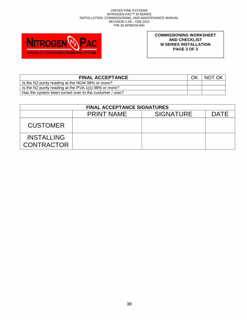
UNITED FIRE SYSTEMS NITROGEN-PAC™ M SERIES
INSTALLATION, COMMISSIONING, AND MAINTENANCE MANUAL REVISION 1.00 – FEB 2015
P/N 30-NPMICM-000
38
FINAL ACCEPTANCE OK NOT OK Is the N2 purity reading at the NGM 98% or more? Is the N2 purity reading at the PVA-1(s) 98% or more? Has the system been turned over to the customer / user?
FINAL ACCEPTANCE SIGNATURES
PRINT NAME SIGNATURE DATE
CUSTOMER
INSTALLING CONTRACTOR
COMMISSIONING WORKSHEET AND CHECKLIST
M SERIES INSTALLATION PAGE 3 OF 3
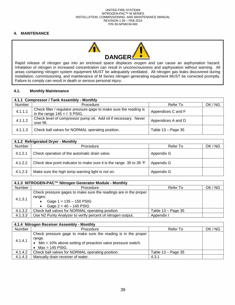
INSTALLATION,
4. MAINTENANCE 4.1. Monthly Maintenance 4.1.1 Compressor / Tank Assembly - MonthlyNumber Procedure
4.1.1.1 Check filter / regulator pressure gage to make sure thein the range 145 + /- 5 PSIG.
4.1.1.2 Check level of compressor pump oil. Add oil if necessary.over fill.
4.1.1.3 Check ball valves for NORMAL operating position.
4.1.2 Refrigerated Dryer - Monthly Number Procedure
4.1.2.1 Check operation of the automatic drain valve
4.1.2.2 Check dew point indicator to make sure it is the range
4.1.2.3 Make sure the high temp warning light is not on.
4.1.3 NITROGEN-PAC™ Nitrogen Generator Module Number Procedure
4.1.3.1
Check pressure gages to make sure theranges:
• Gage 1 = 135 – 150 PSIG• Gage 2 = 40 – 145 PSIG
4.1.3.2 Check ball valves for NORMAL operating position. 4.1.3.3 Use N2 Purity Analyzer to verify percent of nitrogen output.
4.1.4 Nitrogen Receiver Assembly - MonthlyNumber Procedure
4.1.4.1
Check pressure gage to make sure therange. • Min = 10% above setting of preaction valve pressure switch.• Max = 145 PSIG.
4.1.4.2 Check ball valves for NORMAL operating position. 4.1.4.3 Manually drain receiver of water.
Rapid release of nitrogen gas into an enclosed space displaces oxygen and can cause an asphyxiation hazard. Inhalation of nitrogen in increased concentration can result in unconsciousness and asphyxiation without warning. All areas containing nitrogen system equipment MUST be adequately ventilated. All nitrogen gas leaks discovered during installation, commissioning, and maintenance of M Series nitrogen generating equipment MUST be corrected promptly. Failure to comply can result in death or serious personal injury.
UNITED FIRE SYSTEMS NITROGEN-PAC™ M SERIES
INSTALLATION, COMMISSIONING, AND MAINTENANCE MANUAL REVISION 1.00 – FEB 2015
P/N 30-NPMICM-000
39
Monthly Procedure Refer To
regulator pressure gage to make sure the reading is Appendices C
Check level of compressor pump oil. Add oil if necessary. Never Appendices A and
Check ball valves for NORMAL operating position. Table 13 – Page 3
Procedure Refer To
Check operation of the automatic drain valve. Appendix G
heck dew point indicator to make sure it is the range 35 to 39 °F Appendix G
Make sure the high temp warning light is not on. Appendix G
PAC™ Nitrogen Generator Module - Monthly Procedure Refer To
to make sure the readings are in the proper
PSIG PSIG
Check ball valves for NORMAL operating position. Table 13 – Page 3Use N2 Purity Analyzer to verify percent of nitrogen output. Appendix I
Monthly Procedure Refer To
pressure gage to make sure the reading is in the proper
Min = 10% above setting of preaction valve pressure switch.
Check ball valves for NORMAL operating position. Table 13 – Page 3water. 4.3.1
DANGER Rapid release of nitrogen gas into an enclosed space displaces oxygen and can cause an asphyxiation hazard. Inhalation of nitrogen in increased concentration can result in unconsciousness and asphyxiation without warning. All areas containing nitrogen system equipment MUST be adequately ventilated. All nitrogen gas leaks discovered during installation, commissioning, and maintenance of M Series nitrogen generating equipment MUST be corrected promptly.
sult in death or serious personal injury.
Refer To OK / NG
and F
and D
Page 35
Refer To OK / NG
Refer To OK / NG
Page 35
Refer To OK / NG
Page 35
Rapid release of nitrogen gas into an enclosed space displaces oxygen and can cause an asphyxiation hazard. Inhalation of nitrogen in increased concentration can result in unconsciousness and asphyxiation without warning. All areas containing nitrogen system equipment MUST be adequately ventilated. All nitrogen gas leaks discovered during installation, commissioning, and maintenance of M Series nitrogen generating equipment MUST be corrected promptly.
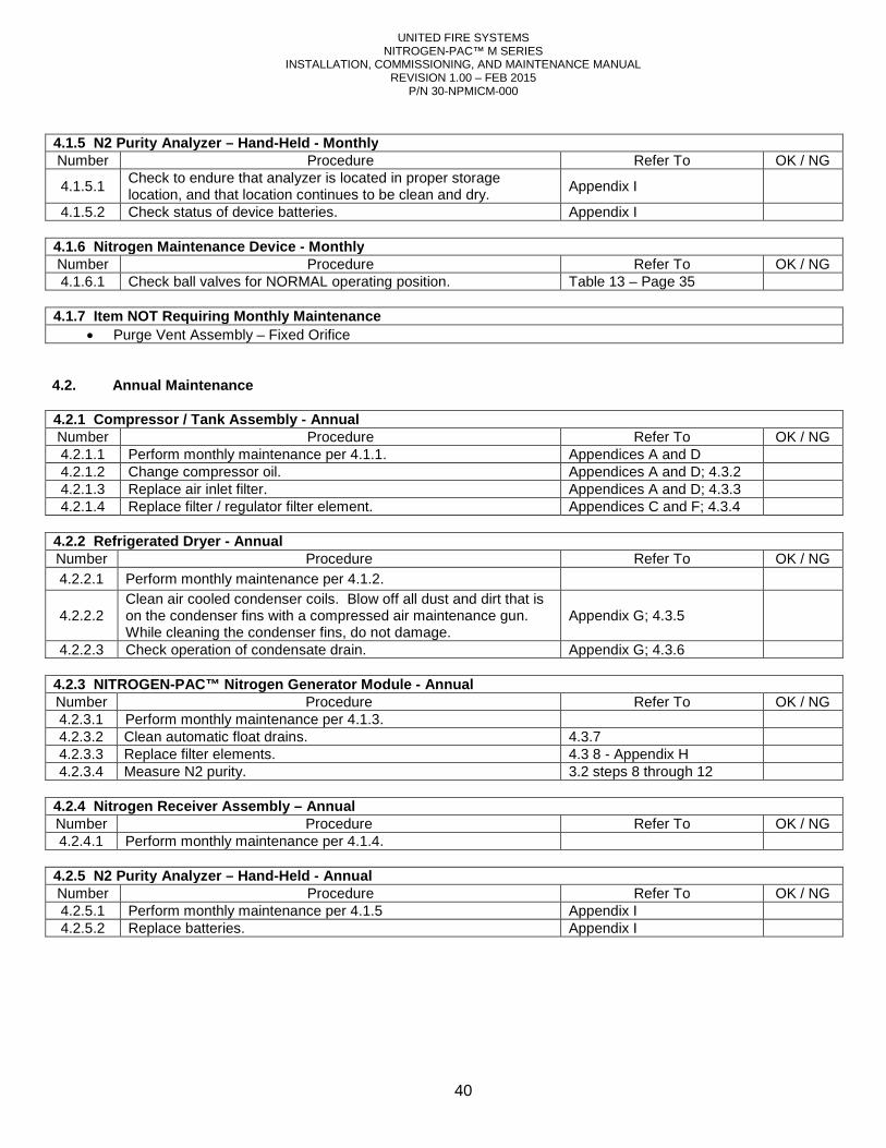
UNITED FIRE SYSTEMS NITROGEN-PAC™ M SERIES
INSTALLATION, COMMISSIONING, AND MAINTENANCE MANUAL REVISION 1.00 – FEB 2015
P/N 30-NPMICM-000
40
4.1.5 N2 Purity Analyzer – Hand-Held - Monthly Number Procedure Refer To OK / NG
4.1.5.1 Check to endure that analyzer is located in proper storage location, and that location continues to be clean and dry.
Appendix I
4.1.5.2 Check status of device batteries. Appendix I
4.1.6 Nitrogen Maintenance Device - Monthly Number Procedure Refer To OK / NG 4.1.6.1 Check ball valves for NORMAL operating position. Table 13 – Page 35
4.1.7 Item NOT Requiring Monthly Maintenance
• Purge Vent Assembly – Fixed Orifice 4.2. Annual Maintenance 4.2.1 Compressor / Tank Assembly - Annual Number Procedure Refer To OK / NG 4.2.1.1 Perform monthly maintenance per 4.1.1. Appendices A and D 4.2.1.2 Change compressor oil. Appendices A and D; 4.3.2 4.2.1.3 Replace air inlet filter. Appendices A and D; 4.3.3 4.2.1.4 Replace filter / regulator filter element. Appendices C and F; 4.3.4
4.2.2 Refrigerated Dryer - Annual Number Procedure Refer To OK / NG 4.2.2.1 Perform monthly maintenance per 4.1.2.
4.2.2.2 Clean air cooled condenser coils. Blow off all dust and dirt that is on the condenser fins with a compressed air maintenance gun. While cleaning the condenser fins, do not damage.
Appendix G; 4.3.5
4.2.2.3 Check operation of condensate drain. Appendix G; 4.3.6 4.2.3 NITROGEN-PAC™ Nitrogen Generator Module - Annual Number Procedure Refer To OK / NG 4.2.3.1 Perform monthly maintenance per 4.1.3. 4.2.3.2 Clean automatic float drains. 4.3.7 4.2.3.3 Replace filter elements. 4.3 8 - Appendix H 4.2.3.4 Measure N2 purity. 3.2 steps 8 through 12
4.2.4 Nitrogen Receiver Assembly – Annual Number Procedure Refer To OK / NG 4.2.4.1 Perform monthly maintenance per 4.1.4.
4.2.5 N2 Purity Analyzer – Hand-Held - Annual Number Procedure Refer To OK / NG 4.2.5.1 Perform monthly maintenance per 4.1.5 Appendix I 4.2.5.2 Replace batteries. Appendix I
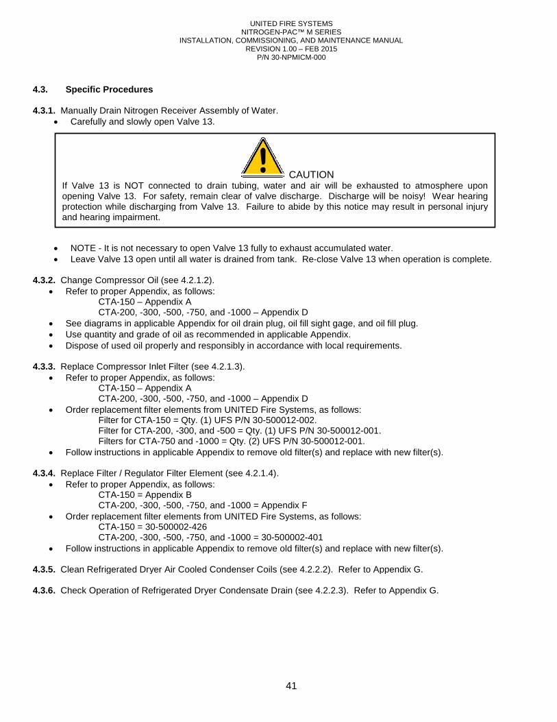
INSTALLATION,
4.3. Specific Procedures 4.3.1. Manually Drain Nitrogen Receiver Assembly of Water.
• Carefully and slowly open Valve 13.
• NOTE - It is not necessary to open Valve 13 fully to exhaust accumulated water.• Leave Valve 13 open until all water is
4.3.2. Change Compressor Oil (see 4.2.1.2
• Refer to proper Appendix, as follows: CTA-150 – Appendix A CTA-200, -300, -500, -750, and
• See diagrams in applicable Appendi• Use quantity and grade of oil as recommended in applicable Appendix.• Dispose of used oil properly and responsibly in accordance with local requirements.
4.3.3. Replace Compressor Inlet Filter (see
• Refer to proper Appendix, as follows: CTA-150 – Appendix A CTA-200, -300, -500, -750, and
• Order replacement filter elements from UNITED Fire Systems, as follows: Filter for CTA-150 = Qty. (1) UFS P/N Filter for CTA-200, -300, and Filters for CTA-750 and -1000 = Qty. (2) UFS P/N
• Follow instructions in applicable Appendix to remove old filter(s) and replace with new filter(s). 4.3.4. Replace Filter / Regulator Filter Element (see
• Refer to proper Appendix, as follows: CTA-150 = Appendix B CTA-200, -300, -500, -750, and
• Order replacement filter elements from UNITED Fire Systems, as follows: CTA-150 = 30-500002-426 CTA-200, -300, -500, -750, and
• Follow instructions in applicable Appendix to remove old filter(s) and replace with new filter(s). 4.3.5. Clean Refrigerated Dryer Air Cooled Condenser Coils 4.3.6. Check Operation of Refrigerated Dryer Condensate Drain
If Valve 13 is NOT connected to drain tubing, water and air will be exhausted to atmosphere upon opening Valve 13. For safety, remain clear of valve discharge. Discharge will be noisy! Wear hearing protection while discharging from Valve 13. Failure to abide by this notice may result in personal injury and hearing impairment.
UNITED FIRE SYSTEMS NITROGEN-PAC™ M SERIES
INSTALLATION, COMMISSIONING, AND MAINTENANCE MANUAL REVISION 1.00 – FEB 2015
P/N 30-NPMICM-000
41
Manually Drain Nitrogen Receiver Assembly of Water. open Valve 13.
It is not necessary to open Valve 13 fully to exhaust accumulated water. Leave Valve 13 open until all water is drained from tank. Re-close Valve 13 when operation is complete.
4.2.1.2). Refer to proper Appendix, as follows:
750, and -1000 – Appendix D See diagrams in applicable Appendix for oil drain plug, oil fill sight gage, and oil fill plug.Use quantity and grade of oil as recommended in applicable Appendix. Dispose of used oil properly and responsibly in accordance with local requirements.
Replace Compressor Inlet Filter (see 4.2.1.3). Refer to proper Appendix, as follows:
750, and -1000 – Appendix D from UNITED Fire Systems, as follows:
150 = Qty. (1) UFS P/N 30-500012-002. 300, and -500 = Qty. (1) UFS P/N 30-500012-001.
1000 = Qty. (2) UFS P/N 30-500012-001. Follow instructions in applicable Appendix to remove old filter(s) and replace with new filter(s).
gulator Filter Element (see 4.2.1.4). Refer to proper Appendix, as follows:
750, and -1000 = Appendix F Order replacement filter elements from UNITED Fire Systems, as follows:
750, and -1000 = 30-500002-401
Follow instructions in applicable Appendix to remove old filter(s) and replace with new filter(s).
Clean Refrigerated Dryer Air Cooled Condenser Coils (see 4.2.2.2). Refer to Appendix G
Check Operation of Refrigerated Dryer Condensate Drain (see 4.2.2.3). Refer to Appendix G
CAUTION If Valve 13 is NOT connected to drain tubing, water and air will be exhausted to atmosphere upon opening Valve 13. For safety, remain clear of valve discharge. Discharge will be noisy! Wear hearing
ction while discharging from Valve 13. Failure to abide by this notice may result in personal injury
close Valve 13 when operation is complete.
x for oil drain plug, oil fill sight gage, and oil fill plug.
Follow instructions in applicable Appendix to remove old filter(s) and replace with new filter(s).
Follow instructions in applicable Appendix to remove old filter(s) and replace with new filter(s).
Appendix G.
Appendix G.
If Valve 13 is NOT connected to drain tubing, water and air will be exhausted to atmosphere upon opening Valve 13. For safety, remain clear of valve discharge. Discharge will be noisy! Wear hearing
ction while discharging from Valve 13. Failure to abide by this notice may result in personal injury
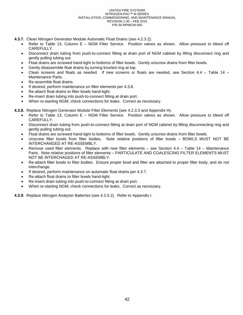
UNITED FIRE SYSTEMS NITROGEN-PAC™ M SERIES
INSTALLATION, COMMISSIONING, AND MAINTENANCE MANUAL REVISION 1.00 – FEB 2015
P/N 30-NPMICM-000
42
4.3.7. Clean Nitrogen Generator Module Automatic Float Drains (see 4.2.3 2).
• Refer to Table 13, Column E – NGM Filter Service. Position valves as shown. Allow pressure to bleed off CAREFULLY.
• Disconnect drain tubing from push-to-connect fitting at drain port of NGM cabinet by lifting disconnect ring and gently pulling tubing out.
• Float drains are screwed hand-tight to bottoms of filter bowls. Gently unscrew drains from filter bowls. • Gently disassemble float drains by turning knurled ring at top. • Clean screens and floats as needed. If new screens or floats are needed, see Section 4.4 – Table 14 –
Maintenance Parts. • Re-assemble float drains. • If desired, perform maintenance on filter elements per 4.3.8. • Re-attach float drains to filter bowls hand-tight. • Re-insert drain tubing into push-to-connect fitting at drain port. • When re-starting NGM, check connections for leaks. Correct as necessary.
4.3.8. Replace Nitrogen Generator Module Filter Elements (see 4.2.3.3 and Appendix H).
• Refer to Table 13, Column E – NGM Filter Service. Position valves as shown. Allow pressure to bleed off CAREFULLY.
• Disconnect drain tubing from push-to-connect fitting at drain port of NGM cabinet by lifting disconnecting ring and gently pulling tubing out.
• Float drains are screwed hand-tight to bottoms of filter bowls. Gently unscrew drains from filter bowls. • Unscrew filter bowls from filter bodies. Note relative positions of filter bowls – BOWLS MUST NOT BE
INTERCHANGED AT RE-ASSEMBLY. • Remove used filter elements. Replace with new filter elements – see Section 4.4 – Table 14 – Maintenance
Parts. Note relative positions of filter elements – PARTICULATE AND COALESCING FILTER ELEMENTS MUST NOT BE INTERCHAGED AT RE-ASSEMBLY.
• Re-attach filter bowls to filter bodies. Ensure proper bowl and filter are attached to proper filter body, and do not interchange.
• If desired, perform maintenance on automatic float drains per 4.3.7. • Re-attach float drains to filter bowls hand-tight. • Re-insert drain tubing into push-to-connect fitting at drain port. • When re-starting NGM, check connections for leaks. Correct as necessary.
4.3.9. Replace Nitrogen Analyzer Batteries (see 4.2.5.2). Refer to Appendix I.
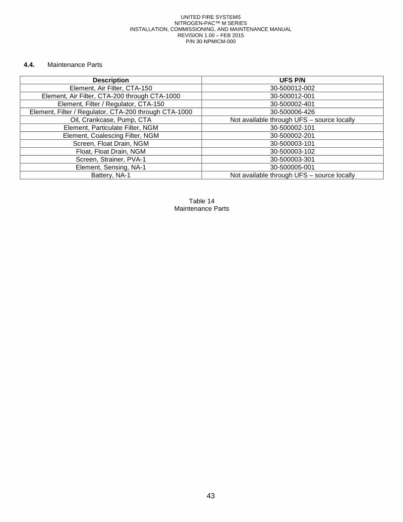
UNITED FIRE SYSTEMS NITROGEN-PAC™ M SERIES
INSTALLATION, COMMISSIONING, AND MAINTENANCE MANUAL REVISION 1.00 – FEB 2015
P/N 30-NPMICM-000
43
4.4. Maintenance Parts
Description UFS P/N Element, Air Filter, CTA-150 30-500012-002
Element, Air Filter, CTA-200 through CTA-1000 30-500012-001 Element, Filter / Regulator, CTA-150 30-500002-401
Element, Filter / Regulator, CTA-200 through CTA-1000 30-500006-426 Oil, Crankcase, Pump, CTA Not available through UFS – source locally
Element, Particulate Filter, NGM 30-500002-101 Element, Coalescing Filter, NGM 30-500002-201
Screen, Float Drain, NGM 30-500003-101 Float, Float Drain, NGM 30-500003-102 Screen, Strainer, PVA-1 30-500003-301 Element, Sensing, NA-1 30-500005-001
Battery, NA-1 Not available through UFS – source locally
Table 14 Maintenance Parts
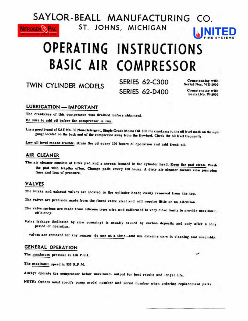
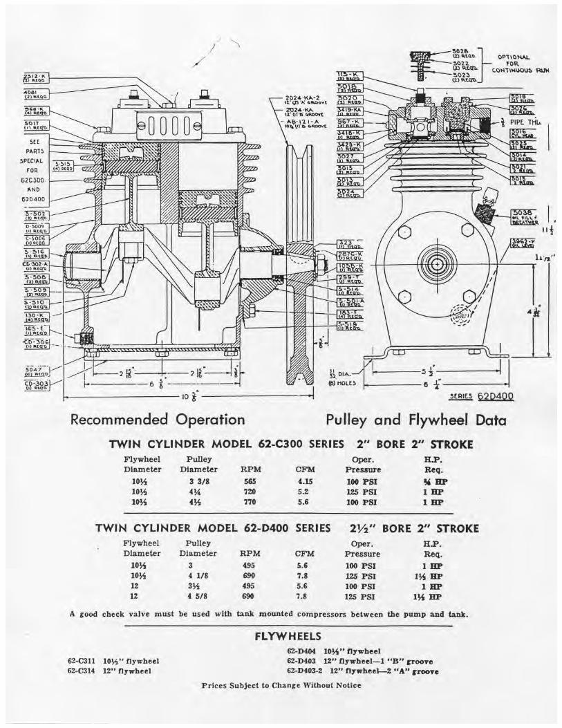
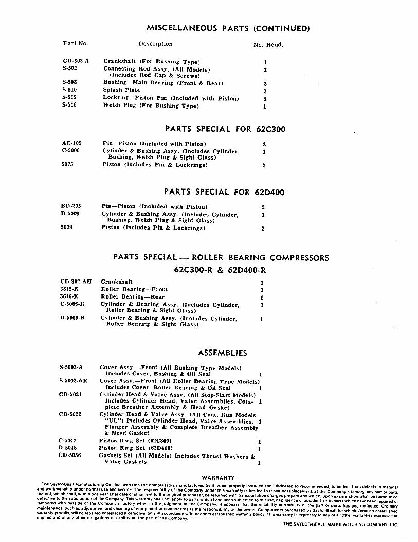
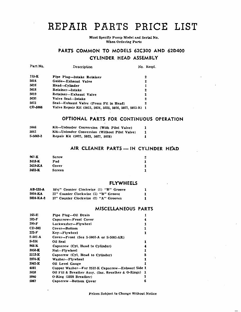
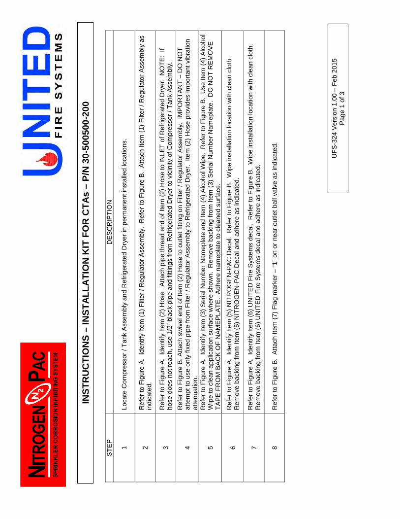
INS
TR
UC
TIO
NS
– IN
ST
ALL
AT
ION
KIT
FO
R C
TA
s –
P/N
30-
5005
00-2
00
ST
EP
D
ES
CR
IPT
ION
1 Lo
cate
Com
pres
sor
/ Tan
k A
ssem
bly
and
Ref
riger
ated
Dry
er in
per
man
ent i
nsta
lled
loca
tions
.
2 R
efer
to F
igur
e A
. Id
entif
y Ite
m (
1) F
ilter
/ R
egul
ator
Ass
embl
y. R
efer
to F
igur
e B
. A
ttach
Item
(1)
Filt
er /
Reg
ulat
or A
ssem
bly
as
indi
cate
d.
3 R
efer
to F
igur
e A
. Id
entif
y Ite
m (
2) H
ose.
Atta
ch p
ipe
thre
ad e
nd o
f Ite
m (
2) H
ose
to IN
LET
of R
efrig
erat
ed D
ryer
. N
OT
E:
If ho
se d
oes
not r
each
, use
1/2
” bl
ack
pipe
and
fitti
ngs
from
Ref
riger
ated
Dry
er to
vic
inity
of C
ompr
esso
r / T
ank
Ass
embl
y.
4 R
efer
to F
igur
e B
. Atta
ch s
wiv
el e
nd o
f Ite
m (
2) H
ose
to o
utle
t fitt
ing
on F
ilter
/ R
egul
ator
Ass
embl
y. I
MP
OR
TA
NT
– D
O N
OT
at
tem
pt to
use
onl
y fix
ed p
ipe
from
Filt
er /
Reg
ulat
or A
ssem
bly
to R
efrig
erat
ed D
ryer
. Ite
m (
2) H
ose
prov
ides
impo
rtan
t vib
ratio
n at
tenu
atio
n.
5 R
efer
to F
igur
e A
. Id
entif
y Ite
m (
3) S
eria
l Num
ber
Nam
epla
te a
nd It
em (
4) A
lcoh
ol W
ipe.
Ref
er to
Fig
ure
B.
Use
Item
(4)
Alc
ohol
W
ipe
to c
lean
app
licat
ion
surf
ace
whe
re s
how
n. R
emov
e ba
ckin
g fr
om It
em (
3) S
eria
l Num
ber
Nam
epla
te.
DO
NO
T R
EM
OV
E
TA
PE
FR
OM
BA
CK
OF
NA
ME
PLA
TE
. A
dher
e na
mep
late
to c
lean
ed s
urfa
ce.
6 R
efer
to F
igur
e A
. Id
entif
y Ite
m (
5) N
ITR
OG
EN
-PA
C D
ecal
. R
efer
to F
igur
e B
. W
ipe
inst
alla
tion
loca
tion
with
cle
an c
loth
. R
emov
e ba
ckin
g fr
om It
em (
5) N
ITR
OG
EN
-PA
C D
ecal
and
adh
ere
as in
dica
ted.
7 R
efer
to F
igur
e A
. Id
entif
y Ite
m (
6) U
NIT
ED
Fire
Sys
tem
s de
cal.
Ref
er to
Fig
ure
B.
Wip
e in
stal
latio
n lo
catio
n w
ith c
lean
clo
th.
Rem
ove
back
ing
from
Item
(6)
UN
ITE
D F
ire S
yste
ms
deca
l and
adh
ere
as in
dica
ted.
8 R
efer
to F
igur
e B
. A
ttach
Item
(7)
Fla
g m
arke
r –
“1”
on o
r ne
ar o
utle
t bal
l val
ve a
s in
dica
ted.
UF
S-3
24 V
ersi
on 1
.00
– F
eb 2
015
Pag
e 1
of 3
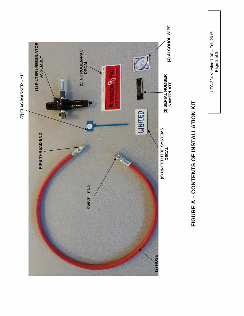
(2)
HO
SE
(6
) U
NIT
ED
FIR
E S
YS
TE
MS
D
EC
AL
(5)
NIT
RO
GE
N-P
AC
D
EC
AL
(7)
FLA
G M
AR
KE
R –
“1”
FIG
UR
E A
– C
ON
TE
NT
S O
F IN
ST
ALL
AT
ION
KIT
UF
S-3
24 V
ersi
on 1
.00
– F
eb 2
015
Pag
e 2
of 3
PIP
E T
HR
EA
D E
ND
SW
IVE
L E
ND
(1)
FIL
TE
R /
RE
GU
LAT
OR
A
SS
EM
BLY
(4)
ALC
OH
OL
WIP
E
(3)
SE
RIA
L N
UM
BE
R
NA
ME
PLA
TE
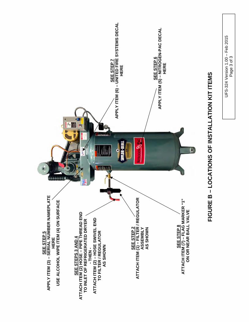
FIG
UR
E B
– L
OC
AT
ION
S O
F IN
ST
ALL
AT
ION
KIT
ITE
MS
SE
E S
TE
PS
3 A
ND
4
AT
TA
CH
ITE
M (
2) H
OS
E –
PIP
E T
HR
EA
D E
ND
T
O IN
LET
OF
RE
FR
IGE
RA
TE
D D
RY
ER
-
TH
EN
-
AT
TA
CH
ITE
M (
2) –
HO
SE
SW
IVE
L E
ND
T
O F
ILT
ER
/ R
EG
ULA
TO
R
AS
SH
OW
N
UF
S-3
24 V
ersi
on 1
.00
– F
eb 2
015
Pag
e 3
of 3
SE
E S
TE
P 2
A
TT
AC
H IT
EM
(1)
– F
ILT
ER
/ R
EG
ULA
TO
R
AS
SE
MB
LY
AS
SH
OW
N
SE
E S
TE
P 8
A
TT
AC
H IT
EM
(7)
– F
LAG
MA
RK
ER
“1”
O
N O
R N
EA
R B
ALL
VA
LVE
SE
E S
TE
P 5
A
PP
LY IT
EM
(3)
– S
ER
IAL
NU
MB
ER
NA
ME
PLA
TE
H
ER
E
US
E A
LCO
HO
L W
IPE
ITE
M (
4) O
N S
UR
FA
CE
SE
E S
TE
P 7
A
PP
LY IT
EM
(6)
– U
NIT
ED
FIR
E S
YS
TE
MS
DE
CA
L H
ER
E
SE
E S
TE
P 6
A
PP
LY IT
EM
(5)
– N
ITR
OG
EN
-PA
C D
EC
AL
HE
RE

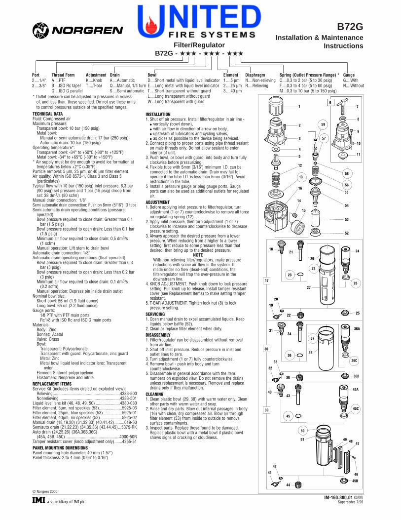
B72GInstallation & Maintenance
InstructionsFilter/RegulatorB72G - ��� - ��� - ���
Thread FormA....PTFB....ISO Rc taperG....ISO G parallel
INSTALLATION1. Shut off air pressure. Install filter/regulator in air line -
� vertically (bowl down),� with air flow in direction of arrow on body,� upstream of lubricators and cycling valves,� as close as possible to the device being serviced.
2. Connect piping to proper ports using pipe thread sealanton male threads only. Do not allow sealant to enterinterior of unit.
3. Push bowl, or bowl with guard, into body and turn fullyclockwise before pressurizing.
4. Flexible tube with 5mm (3/16") minimum I.D. can beconnected to the automatic drain. Drain may fail tooperate if the tube I.D. is less than 5mm (3/16"). Avoidrestrictions in the tube.
5 Install a pressure gauge or plug gauge ports. Gaugeports can also be used as additional outlets for regulatedair.
ADJUSTMENT1. Before applying inlet pressure to filter/regulator, turn
adjustment (1 or 7) counterclockwise to remove all forceon regulating spring (12).
2. Apply inlet pressure, then turn adjustment (1 or 7)clockwise to increase and counterclockwise to decreasepressure setting.
3. Always approach the desired pressure from a lowerpressure. When reducing from a higher to a lowersetting, first reduce to some pressure less than thatdesired, then bring up to the desired pressure.
NOTEWith non-relieving filter/regulators, make pressurereductions with some air flow in the system. Ifmade under no flow (dead-end) conditions, thefilter/regulator will trap the over-pressure in thedownstream line.
4. KNOB ADJUSTMENT. Push knob down to lock pressuresetting. Pull knob up to release. Install tamper resistantcover (see Replacement Items) to make setting tamperresistant.
5. T-BAR ADJUSTMENT. Tighten lock nut (8) to lockpressure setting.
SERVICING1. Open manual drain to expel accumulated liquids. Keep
liquids below baffle (52).2. Clean or replace filter element when dirty.DISASSEMBLY1. Filter/regulator can be disassembled without removal
from air line.2. Shut off inlet pressure. Reduce pressure in inlet and
outlet lines to zero. 3. Turn adjustment (1 or 7) fully counterclockwise.4. Remove bowl - push into body and turn
counterclockwise.5. Disassemble in general accordance with the item
numbers on exploded view. Do not remove the drainsunless replacement is necessary. Remove and replacedrains only if they malfunction.
CLEANING1. Clean plastic bowl (29, 38) with warm water only. Clean
other parts with warm water and soap.2. Rinse and dry parts. Blow out internal passages in body
(16) with clean, dry compressed air. Blow air throughfilter element (53) from inside to outside to removesurface contaminants.
3. Inspect parts. Replace those found to be damaged.Replace plastic bowl with a metal bowl if plastic bowlshows signs of cracking or cloudiness.
TECHNICAL DATAFluid: Compressed airMaximum pressure:
Transparent bowl: 10 bar (150 psig)Metal bowl:
Manual or semi automatic drain: 17 bar (250 psig)Automatic drain: 10 bar (150 psig)
Operating temperature*: Transparent bowl: -34° to +50°C (-30° to +125°F)Metal bowl: -34° to +65°C (-30° to +150°F)
* Air supply must be dry enough to avoid ice formation attemperatures below +2°C (+35°F).
Particle removal: 5 µm, 25 µm, or 40 µm filter elementAir quality: Within ISO 8573-1, Class 3 and Class 5
(particulates)Typical flow with 10 bar (150 psig) inlet pressure, 6,3 bar
(90 psig) set pressure and 1 bar (15 psig) droop from set: 38 dm3/s (80 scfm)
Manual drain connection: 1/8"Semi automatic drain connection: Push on 8mm (5/16") ID tubeSemi automatic drain operating conditions (pressure
operated):Bowl pressure required to close drain: Greater than 0,1
bar (1.5 psig)Bowl pressure required to open drain: Less than 0,1 bar
(1.5 psig)Minimum air flow required to close drain: 0,5 dm3/s
(1 scfm) Manual operation: Lift stem to drain bowl
Automatic drain connection: 1/8"Automatic drain operating conditions (float operated):
Bowl pressure required to close drain: Greater than 0,3 bar (5 psig)
Bowl pressure required to open drain: Less than 0,2 bar (3 psig)
Minimum air flow required to close drain: 0,1 dm3/s (0.2 scfm)
Manual operation: Depress pin inside drain outletNominal bowl size:
Short bowl: 56 ml (1.9 fluid ounce)Long bowl: 65 ml (2.2 fluid ounce)
Gauge ports: 1⁄8 PTF with PTF main portsRc1/8 with ISO Rc and ISO G main ports
Materials:Body: ZincBonnet: AcetalValve: BrassBowl:
Transparent: PolycarbonateTransparent with guard: Polycarbonate, zinc guardMetal: ZincMetal bowl liquid level indicator lens: Transparent
nylon Element: Sintered polypropyleneElastomers: Neoprene and nitrile
REPLACEMENT ITEMSService Kit (includes items circled on exploded view):
Relieving.............................................................4383-500Nonrelieving .......................................................4383-501
Liquid level lens kit (46, 48, 49, 50) ......................4380-030Filter element, 5µm, red speckles (53).....................5925-03Filter element, 25µm, blue speckles (53) .................5925-01Filter element, 40µm, no speckles (53)....................5925-02Manual drain (18,19,20) (31,32,33) (40,41,42).........619-50Semiauto drain (21,22,23) (34,35,36) (43,44,45)...5379-RKAuto drain (24,25,26) (36A,36B,36C)
(45A, 45B, 45C) .................................................4000-50RTamper resistant cover (knob adjustment only).......4255-51PANEL MOUNTING DIMENSIONSPanel mounting hole diameter: 40 mm (1.57")Panel thickness: 2 to 4 mm (0.06" to 0.16")
Port2 ....1/4"3 ....3/8"
* Outlet pressure can be adjusted to pressures in excessof, and less than, those specified. Do not use these unitsto control pressures outside of the specified ranges.
Spring (Outlet Pressure Range) *C....0,3 to 2 bar (5 to 30 psig)F ....0,3 to 4 bar (5 to 60 psig)M...0,3 to 10 bar (5 to 150 psig)
GaugeG....WithN....Without
DiaphragmN....Non-relievingR....Relieving
AdjustmentK....KnobT ....T-bar
DrainA....AutomaticQ....Manual, 1/4 turnS....Semi automatic
BowlD....Short metal with liquid level indicator E ....Long metal with liquid level indicator T ....Short transparent without guardL ....Long transparent without guardW...Long transparent with guard
Element1 ....5 µm2 ....25 µm3....40 µm
1
3
4
5
2
12
13
16
14
15
55
54
53
52
58
56
59
57
11
7
8
9
10
6
17
18
27
20
19
30
39
21
23
22
28
29
25
24
26
47
46
4951 48
41
42
44
50
4043
45
45A
45C
45B
36B35
33
32
3836
36C
3134
37
36A
IM-160.300.01 (2/00)Supersedes 7/98a subsidiary of IMI plc
© Norgren 2000
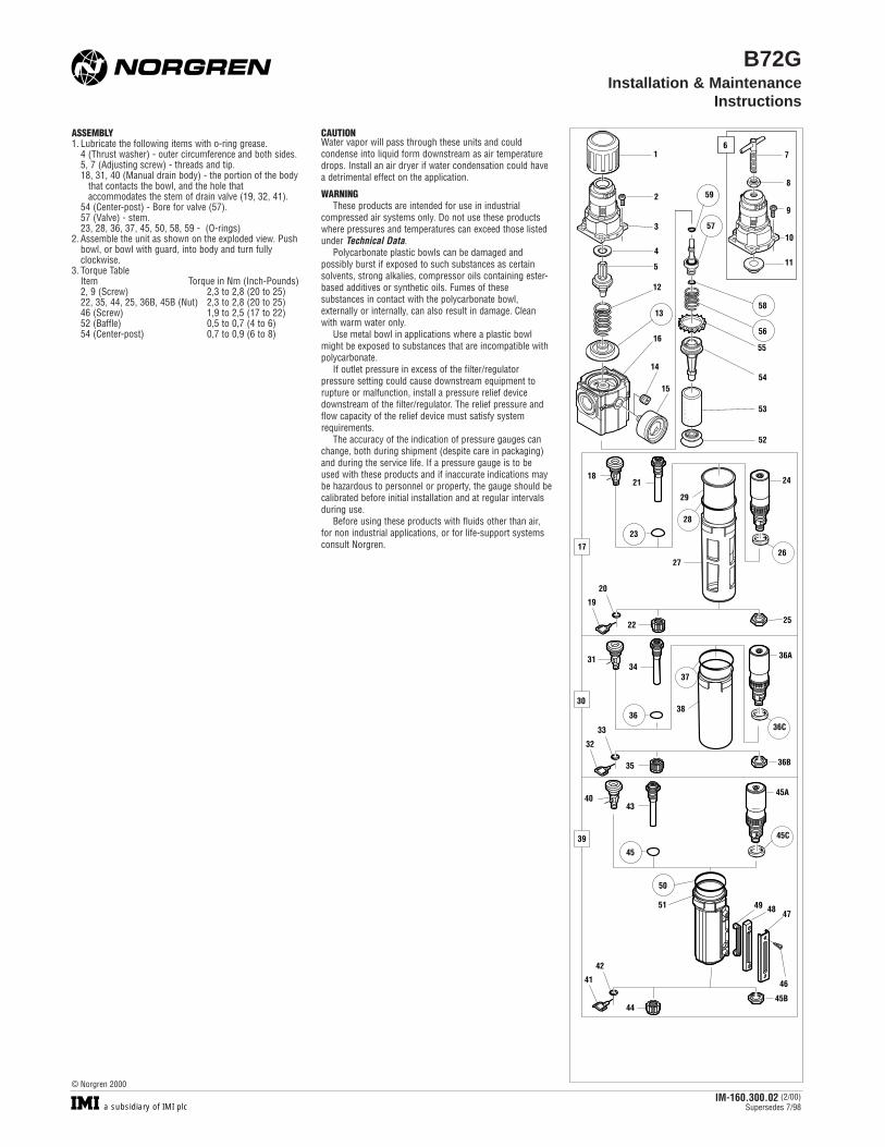
ASSEMBLY1. Lubricate the following items with o-ring grease.
4 (Thrust washer) - outer circumference and both sides.5, 7 (Adjusting screw) - threads and tip.18, 31, 40 (Manual drain body) - the portion of the body
that contacts the bowl, and the hole that accommodates the stem of drain valve (19, 32, 41).
54 (Center-post) - Bore for valve (57).57 (Valve) - stem.23, 28, 36, 37, 45, 50, 58, 59 - (O-rings)
2. Assemble the unit as shown on the exploded view. Pushbowl, or bowl with guard, into body and turn fullyclockwise.
3. Torque TableItem Torque in Nm (Inch-Pounds)2, 9 (Screw) 2,3 to 2,8 (20 to 25)22, 35, 44, 25, 36B, 45B (Nut) 2,3 to 2,8 (20 to 25)46 (Screw) 1,9 to 2,5 (17 to 22)52 (Baffle) 0,5 to 0,7 (4 to 6)54 (Center-post) 0,7 to 0,9 (6 to 8)
B72GInstallation & Maintenance
Instructions
CAUTIONWater vapor will pass through these units and couldcondense into liquid form downstream as air temperaturedrops. Install an air dryer if water condensation could havea detrimental effect on the application.
WARNINGThese products are intended for use in industrial
compressed air systems only. Do not use these productswhere pressures and temperatures can exceed those listedunder Technical Data.
Polycarbonate plastic bowls can be damaged andpossibly burst if exposed to such substances as certainsolvents, strong alkalies, compressor oils containing ester-based additives or synthetic oils. Fumes of thesesubstances in contact with the polycarbonate bowl,externally or internally, can also result in damage. Cleanwith warm water only.
Use metal bowl in applications where a plastic bowlmight be exposed to substances that are incompatible withpolycarbonate.
If outlet pressure in excess of the filter/regulatorpressure setting could cause downstream equipment torupture or malfunction, install a pressure relief devicedownstream of the filter/regulator. The relief pressure andflow capacity of the relief device must satisfy systemrequirements.
The accuracy of the indication of pressure gauges canchange, both during shipment (despite care in packaging)and during the service life. If a pressure gauge is to beused with these products and if inaccurate indications maybe hazardous to personnel or property, the gauge should becalibrated before initial installation and at regular intervalsduring use.
Before using these products with fluids other than air,for non industrial applications, or for life-support systemsconsult Norgren.
IM-160.300.02 (2/00)Supersedes 7/98a subsidiary of IMI plc
© Norgren 2000
1
3
4
5
2
12
13
16
14
15
55
54
53
52
58
56
59
57
11
7
8
9
10
6
17
18
27
20
19
30
39
21
23
22
28
29
25
24
26
47
46
4951 48
41
42
44
50
4043
45
45A
45C
45B
36B35
33
32
3836
36C
3134
37
36A
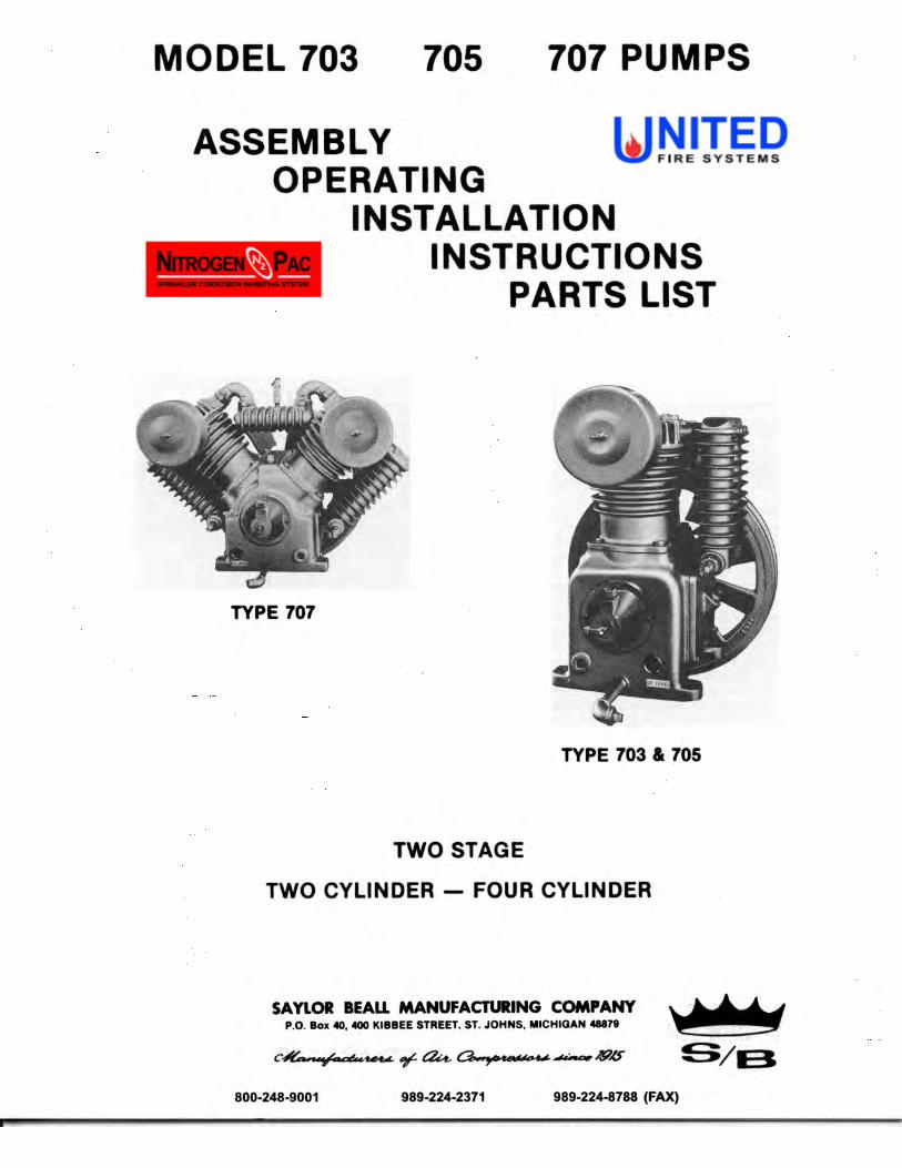
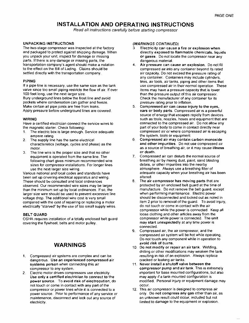
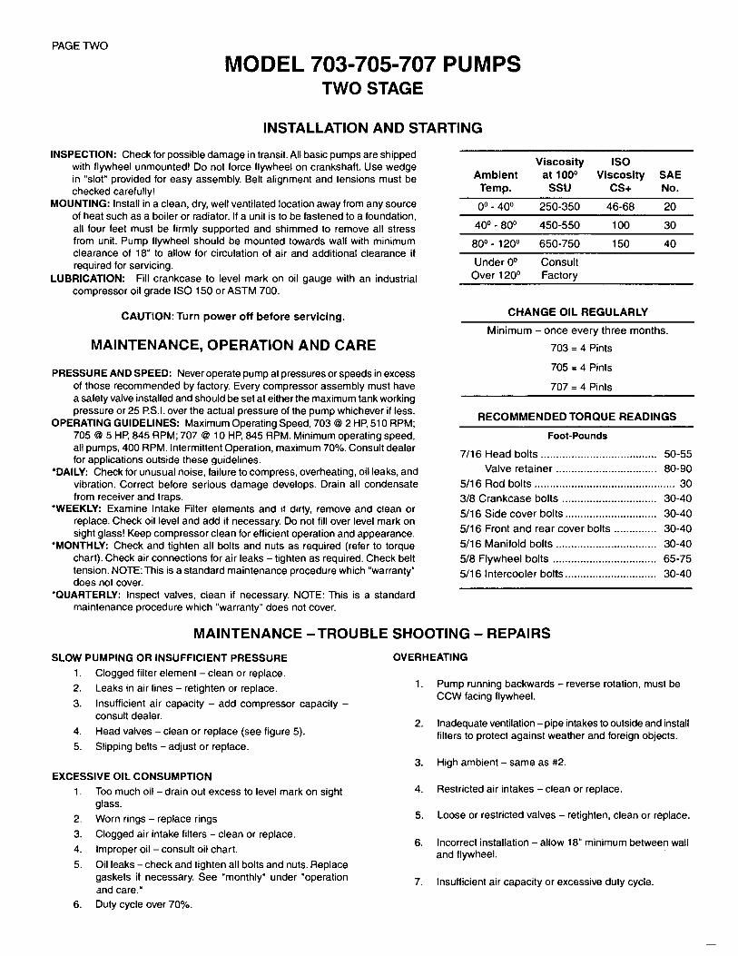
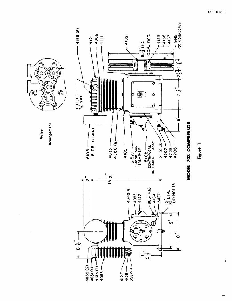
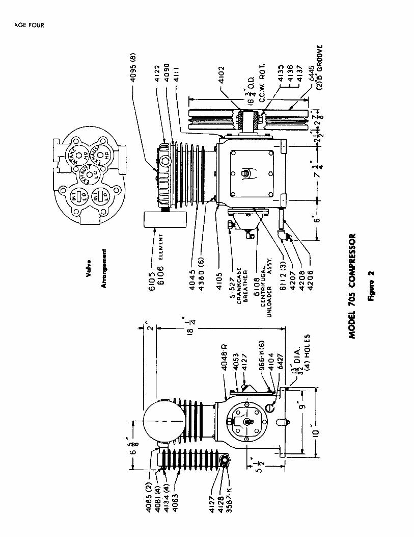
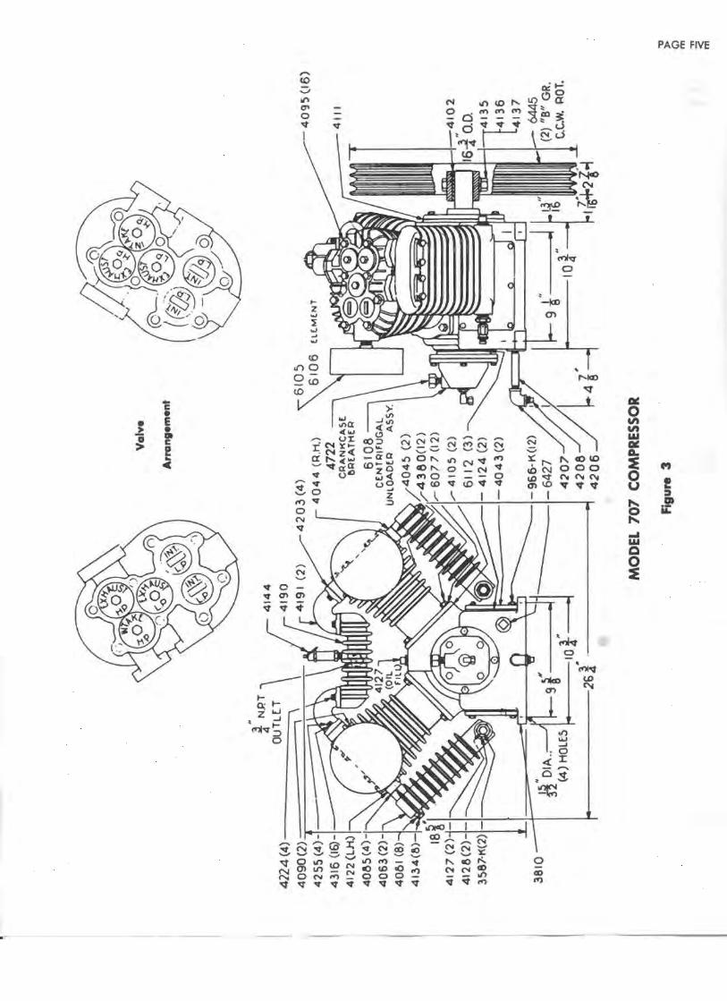
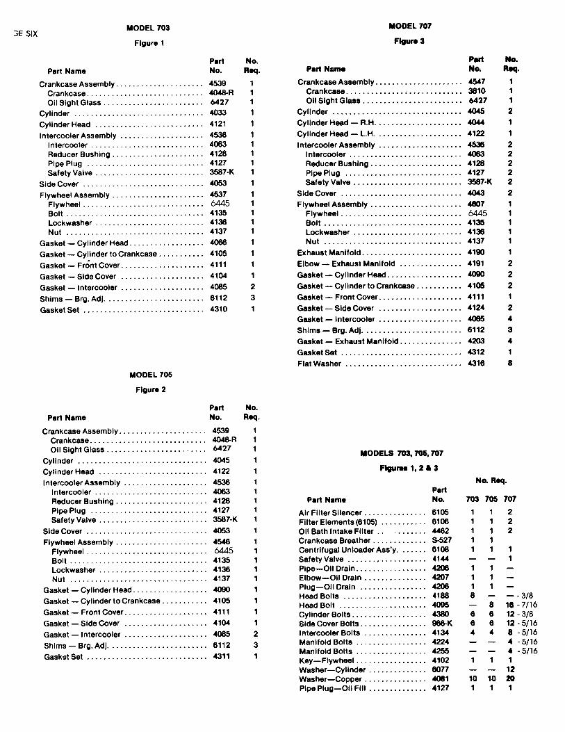
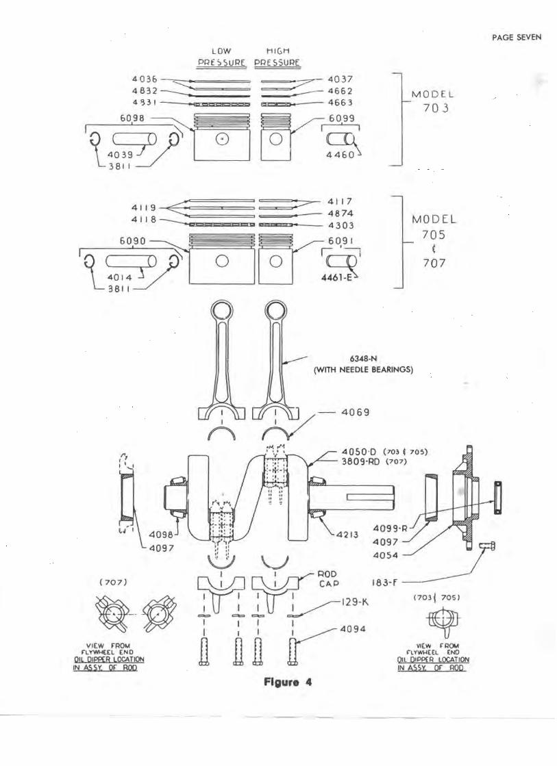
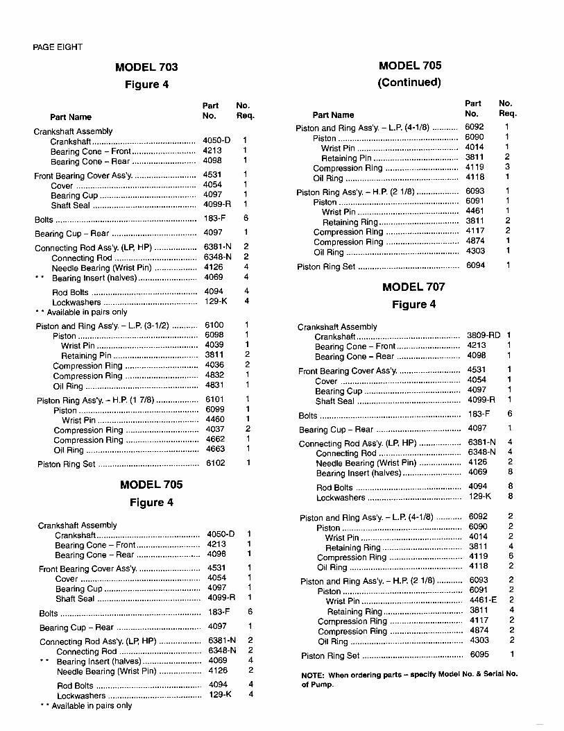
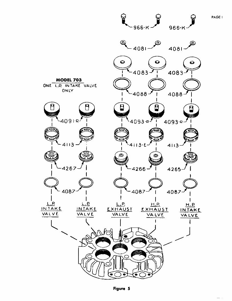
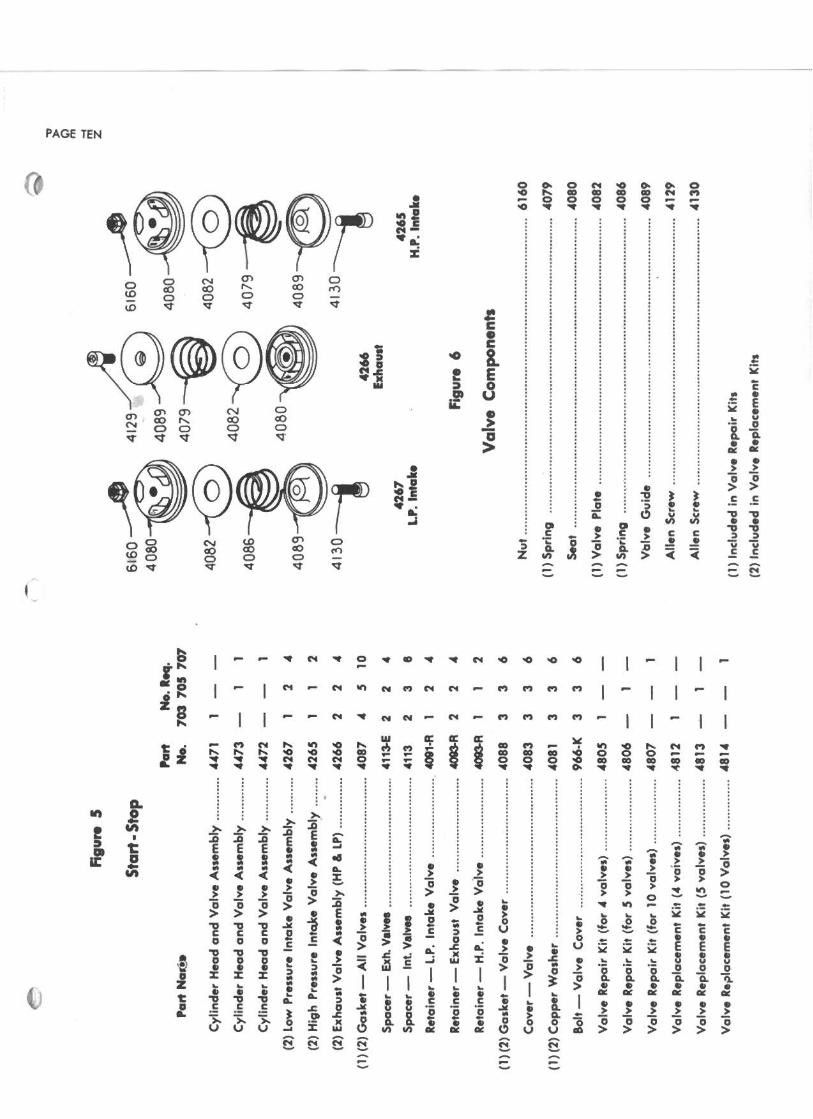
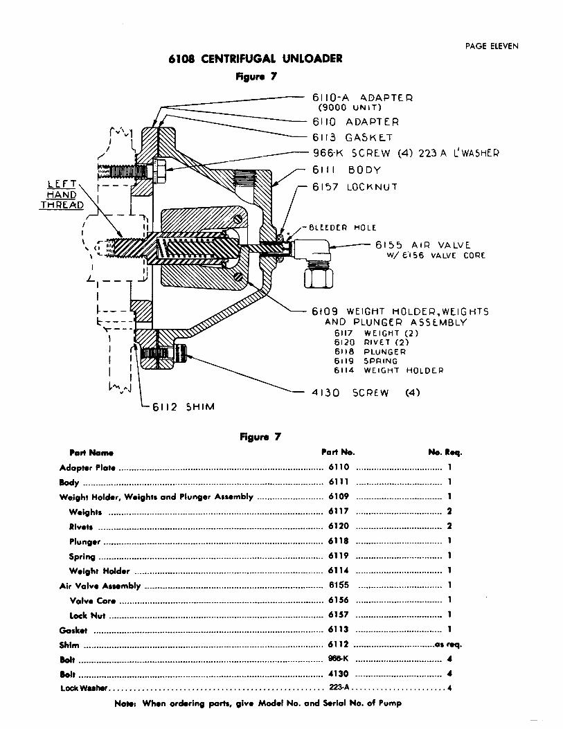
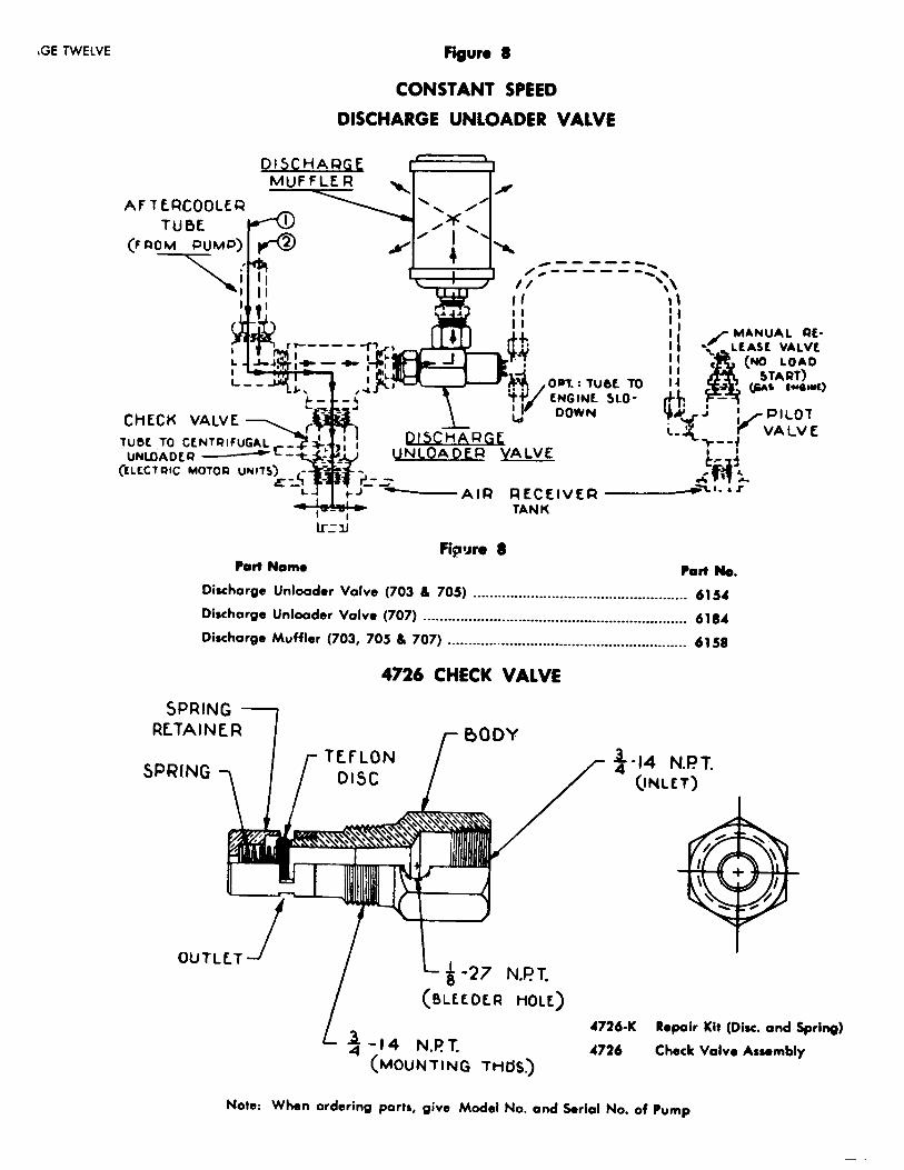
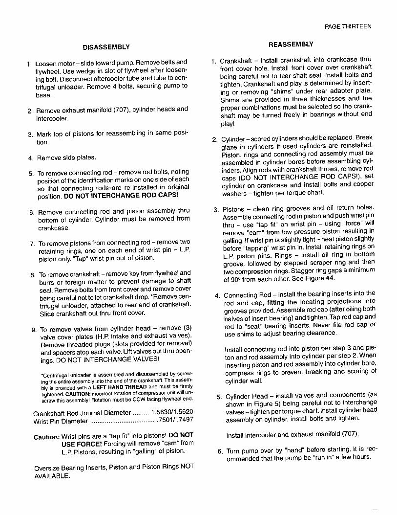
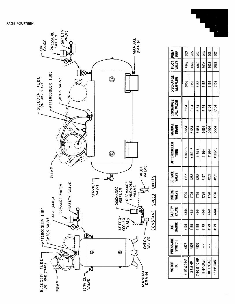
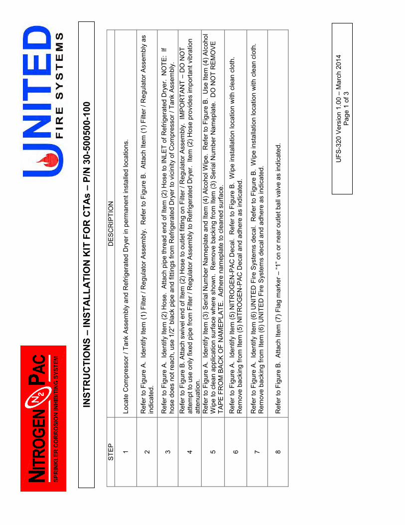
INST
RU
CTI
ON
S –
INST
ALL
ATI
ON
KIT
FO
R C
TAs
– P/
N 3
0-50
0500
-100
STEP
D
ESC
RIP
TIO
N
1 Lo
cate
Com
pres
sor /
Tan
k As
sem
bly
and
Ref
riger
ated
Dry
er in
per
man
ent i
nsta
lled
loca
tions
.
2 R
efer
to F
igur
e A.
Ide
ntify
Item
(1) F
ilter
/ R
egul
ator
Ass
embl
y. R
efer
to F
igur
e B
. At
tach
Item
(1) F
ilter
/ R
egul
ator
Ass
embl
y as
in
dica
ted.
3 R
efer
to F
igur
e A.
Ide
ntify
Item
(2) H
ose.
Atta
ch p
ipe
thre
ad e
nd o
f Ite
m (2
) Hos
e to
INLE
T of
Ref
riger
ated
Dry
er.
NO
TE:
If ho
se d
oes
not r
each
, use
1/2
” bla
ck p
ipe
and
fittin
gs fr
om R
efrig
erat
ed D
ryer
to v
icin
ity o
f Com
pres
sor /
Tan
k As
sem
bly.
4 R
efer
to F
igur
e B.
Atta
ch s
wiv
el e
nd o
f Ite
m (2
) Hos
e to
out
let f
ittin
g on
Filt
er /
Reg
ulat
or A
ssem
bly.
IM
POR
TAN
T –
DO
NO
T at
tem
pt to
use
onl
y fix
ed p
ipe
from
Filt
er /
Reg
ulat
or A
ssem
bly
to R
efrig
erat
ed D
ryer
. Ite
m (2
) Hos
e pr
ovid
es im
porta
nt v
ibra
tion
atte
nuat
ion.
5 R
efer
to F
igur
e A.
Ide
ntify
Item
(3) S
eria
l Num
ber N
amep
late
and
Item
(4) A
lcoh
ol W
ipe.
Ref
er to
Fig
ure
B. U
se It
em (4
) Alc
ohol
W
ipe
to c
lean
app
licat
ion
surfa
ce w
here
sho
wn.
Rem
ove
back
ing
from
Item
(3) S
eria
l Num
ber N
amep
late
. D
O N
OT
REM
OV
E TA
PE F
RO
M B
AC
K O
F N
AM
EPL
ATE.
Adh
ere
nam
epla
te to
cle
aned
sur
face
.
6 R
efer
to F
igur
e A.
Ide
ntify
Item
(5) N
ITR
OG
EN-P
AC D
ecal
. R
efer
to F
igur
e B.
Wip
e in
stal
latio
n lo
catio
n w
ith c
lean
clo
th.
Rem
ove
back
ing
from
Item
(5) N
ITR
OG
EN-P
AC D
ecal
and
adh
ere
as in
dica
ted.
7 R
efer
to F
igur
e A.
Ide
ntify
Item
(6) U
NIT
ED F
ire S
yste
ms
deca
l. R
efer
to F
igur
e B.
Wip
e in
stal
latio
n lo
catio
n w
ith c
lean
clo
th.
Rem
ove
back
ing
from
Item
(6) U
NIT
ED F
ire S
yste
ms
deca
l and
adh
ere
as in
dica
ted.
8 R
efer
to F
igur
e B.
Atta
ch It
em (7
) Fla
g m
arke
r – “1
” on
or n
ear o
utle
t bal
l val
ve a
s in
dica
ted.
UFS
-320
Ver
sion
1.0
0 –
Mar
ch 2
014
Page
1 o
f 3
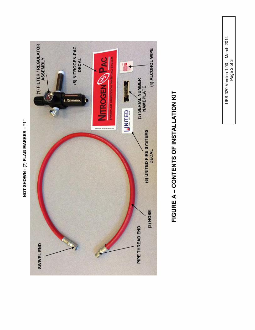
SWIV
EL E
ND
PIPE
TH
REA
D E
ND
(2) H
OSE
(6
) UN
ITED
FIR
E SY
STEM
S D
ECA
L
(3) S
ERIA
L N
UM
BER
N
AMEP
LATE
(4) A
LCO
HO
L W
IPE
(5) N
ITR
OG
EN-P
AC
D
ECA
L
(1) F
ILTE
R /
REG
ULA
TOR
A
SSEM
BLY
NO
T SH
OW
N -
(7) F
LAG
MAR
KER
– “
1”
FIG
UR
E A
– C
ON
TEN
TS O
F IN
STA
LLA
TIO
N K
IT
UFS
-320
Ver
sion
1.0
0 –
Mar
ch 2
014
Page
2 o
f 3
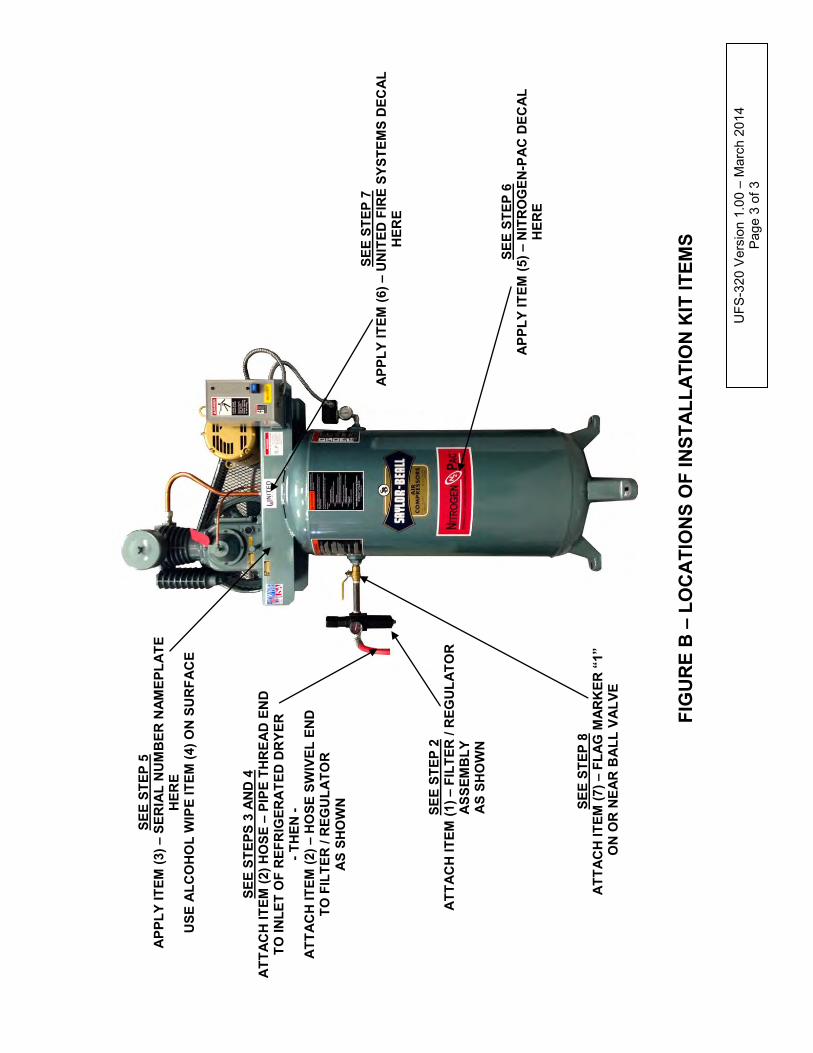
FIG
UR
E B
– L
OC
ATI
ON
S O
F IN
STA
LLA
TIO
N K
IT IT
EMS
SEE
STEP
S 3
AN
D 4
A
TTA
CH
ITEM
(2) H
OSE
– P
IPE
THR
EAD
EN
D
TO IN
LET
OF
REF
RIG
ERA
TED
DR
YER
- T
HEN
- A
TTA
CH
ITEM
(2) –
HO
SE S
WIV
EL E
ND
TO
FIL
TER
/ R
EGU
LATO
R
AS
SHO
WN
UFS
-320
Ver
sion
1.0
0 –
Mar
ch 2
014
Page
3 o
f 3
SEE
STEP
2
ATT
AC
H IT
EM (1
) – F
ILTE
R /
REG
ULA
TOR
A
SSEM
BLY
A
S SH
OW
N
SEE
STEP
8
ATT
AC
H IT
EM (7
) – F
LAG
MAR
KER
“1”
O
N O
R N
EAR
BA
LL V
ALV
E
SEE
STEP
5
APP
LY IT
EM (3
) – S
ERIA
L N
UM
BER
NAM
EPLA
TE
HER
E U
SE A
LCO
HO
L W
IPE
ITEM
(4) O
N S
UR
FAC
E
SEE
STEP
7
APP
LY IT
EM (6
) – U
NIT
ED F
IRE
SYST
EMS
DEC
AL
HER
E
SEE
STEP
6
APP
LY IT
EM (5
) – N
ITR
OG
EN-P
AC
DEC
AL
HER
E

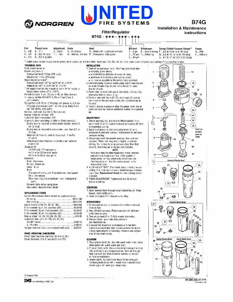
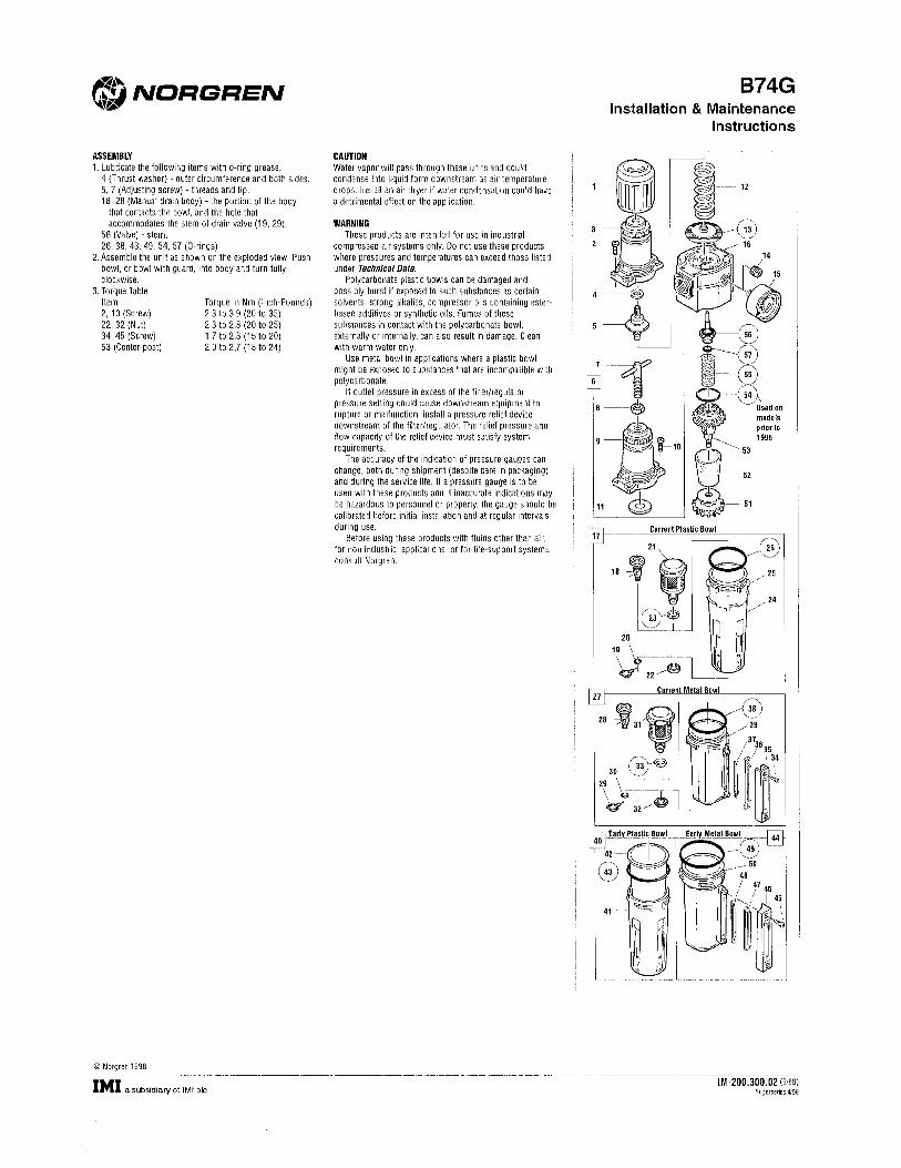
1
Owners ManualRefrigerated Air Dryer
HX10 thru HX55
MODEL____________________
SERIAL____________________
IMPORTANT: READ THIS MANUAL CAREFULLY. IT CONTAINS INFORMATION ABOUT SAFETY AND THE SAFETY OF OTHERS. ALSO BECOME FAMILIAR WITH THE PROPER INSTALLATION AND CONTROLS OF THE AIR DRYER BEFORE OPERATING. ONLY QUALIFIED, TRAINED AND LICENSED PERSONAL SHOULD SERVICE OR OPERATE THIS EQUIPMENT. CAUTION: THIS MACHINE CONTAINS HIGH PRESSURE GAS AND ELECTICITY
RTANT: REOUT
HE PROPER INSTPERATING. ONLRVICE OR O
T SAFETROPER IATING. OCE O
NT: REAY A
R INS
AD THND TALL
QU
_____
HIS MTHE SAATION
____
MANUSAFE
A
UAL CTY O
CAR
OONN: TTHHIOP
SPEERRAAT
QTE
UE
ATALLIIFFI
N E
AANNNDD COOFOF OOT
A. INTRODUCTION
Thank you for selecting an HX series refrigerated air dryer from MACAIR INC. The refrigerated air dryer is specifically designed and manufactured for drying and purifying compressed air generated by an air compressor. Please read this instruction manual carefully before using the air dryer. Please pay attention to the precautions in transportation, installation and operation that are listed in this manual.Please use the dryer according to our application guide and be sure to perform the proper preven-tative maintenance as recommended in this manual. Failure to perform the preventative mainte-nance will void the air dryer warranty. Refrigeration used in this air dryer is environmentally friendly R134a or R404a and is available at local refrigeration wholesalers.Direct any questions not covered in this manual to your distributor or call MACAIR INC. @ 248-624-6300. Before calling with questions always have the air dryer model #, serial # and pressure gauge readings.Service and maintenance can be obtained from your distributor. If you do not know your distribu-tor please contact the factory.Authorization # must be obtained from MACAIR INC. before any parts or dryers are returned to the factory. MACAIR INC. will not be responsible for anything returned without authorization.
CONTENTS PAGE
RECEIVING AND INSPECTION …................................ 3
DATA LABEL ……………………….......………..... 3
HOW THE DRYER WORKS …………….................... 4
INSTALLATION AND LOCATION ….......................… 6
INSTALLATION GUIDE …….…….....................…… 6
DRYER CONTROLS …………….…………............. 6
START UP ……………………………………........ 7
CONTENTS PAGE
INITIAL RUN PROCEDURE …………....................… 7
HOW TO SET THE CONDENSATE DRAIN TIME ….. 7
HOW TO MAKE MINOR REFRIGERANT SUCTION ADJUSTMENTS ……………....................................… 8
NORMAL MAINTENANCE ……………................… 8
AUTO-DRAIN MAINTENANCE …….......................… 8
ELECTRICAL SCHEMATICS ……..…........................... 9
WARRANTY ………………………..........………. 11
2
gerated presse
orease pay attention
is manual.
sed airusing thpay attenmanu
air genhe ai
ctingr dryeeratedry
o t
g an Hyer is s
ed by a
HX serspecifiy an a
ries refically
r com
efrigy demp
e uusee thhe dd
hee pprrec
ppree
hout authare rorizat
eturntion.
ned t
CCOOONNTT
…………………………………
…....
……....
....... 6
..... 7
6
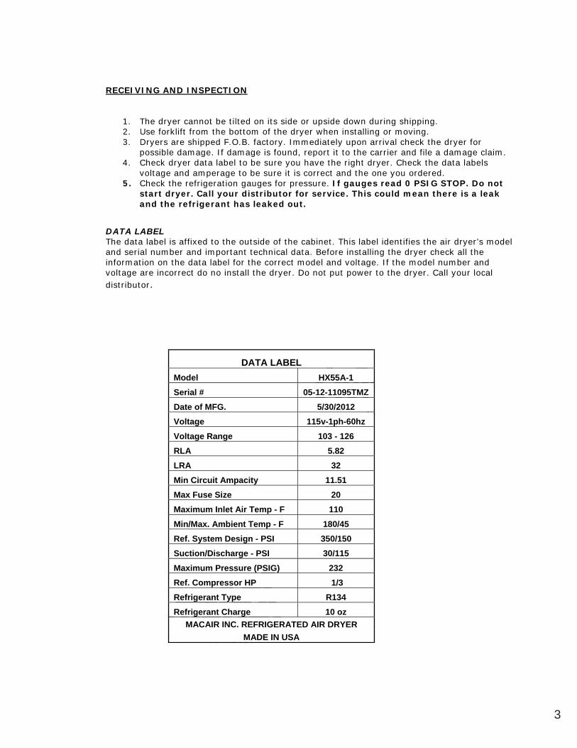
3
RECEIVING AND INSPECTION
1. The dryer cannot be tilted on its side or upside down during shipping. 2. Use forklift from the bottom of the dryer when installing or moving. 3. Dryers are shipped F.O.B. factory. Immediately upon arrival check the dryer for
possible damage. If damage is found, report it to the carrier and file a damage claim. 4. Check dryer data label to be sure you have the right dryer. Check the data labels
voltage and amperage to be sure it is correct and the one you ordered. 5. Check the refrigeration gauges for pressure. If gauges read 0 PSIG STOP. Do not
start dryer. Call your distributor for service. This could mean there is a leak and the refrigerant has leaked out.
DATA LABEL The data label is affixed to the outside of the cabinet. This label identifies the air dryer’s model and serial number and important technical data. Before installing the dryer check all the information on the data label for the correct model and voltage. If the model number and voltage are incorrect do no install the dryer. Do not put power to the dryer. Call your local distributor.
DATA LABEL Model HX55A-1 Serial # 05-12-11095TMZ Date of MFG. 5/30/2012 Voltage 115v-1ph-60hz Voltage Range 103 - 126 RLA 5.82 LRA 32 Min Circuit Ampacity 11.51 Max Fuse Size 20 Maximum Inlet Air Temp - F 110 Min/Max. Ambient Temp - F 180/45 Ref. System Design - PSI 350/150 Suction/Discharge - PSI 30/115 Maximum Pressure (PSIG) 232 Ref. Compressor HP 1/3 Refrigerant Type R134 Refrigerant Charge 10 oz
MACAIR INC. REFRIGERATED AIR DRYER MADE IN USA
1.
oC
23
4
2 UD
The drse foryersssibck
ryer crklift fare sh
dama
cannotfrom thippe
PEC
t be tithe bo
F O
TION
ltedotto
55vCvolttage
draryyer d
agagee. IIf d
.OdO.B. fa
HX-125/30/2012
55A-1095TMZ /20
v 1pphh-6600hh
RefrigRefrige
MAC
geranterant CAIR IN
esst Type
ChargeNC. R
M
r HP
ge EFRIG
SIG
ERMADDE IN
ERN
RAAT
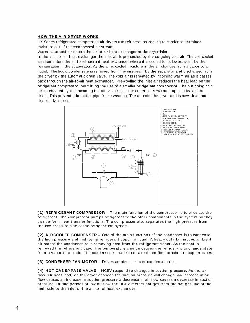
4
HOW THE AIR DRYER WORKS HX Series refrigerated compressed air dryers use refrigeration cooling to condense entrained moisture out of the compressed air stream. Warm saturated air enters the air-to-air heat exchanger at the dryer inlet. In the air –to- air heat exchanger the inlet air is pre-cooled by the outgoing cold air. The pre-cooled air then enters the air to refrigerant heat exchanger where it is cooled to its lowest point by the refrigeration in the evaporator. As the air is cooled moisture in the air changes from a vapor to a liquid. The liquid condensate is removed from the airstream by the separator and discharged from the dryer by the automatic drain valve. The cold air is reheated by incoming warm air as it passes back through the air-to-air heat exchanger. Pre-cooling the inlet air reduces the heat load on the refrigerant compressor, permitting the use of a smaller refrigerant compressor. The out going cold air is reheated by the incoming hot air. As a result the outlet air is warmed up as it leaves the dryer. This prevents the outlet pipe from sweating. The air exits the dryer and is now clean and dry, ready for use.
Diagram B
(1) REFRIGERANT COMPRESSOR – The main function of the compressor is to circulate the refrigerant. The compressor pumps refrigerant to the other components in the system so they can perform heat transfer functions. The compressor also separates the high pressure from the low pressure side of the refrigeration system.
(2) AIRCOOLED CONDENSER – One of the main functions of the condenser is to condense the high pressure and high temp refrigerant vapor to liquid. A heavy duty fan moves ambient air across the condenser coils removing heat from the refrigerant vapor. As the heat is removed the refrigerant vapor the temperature change causes the refrigerant to change state from a vapor to a liquid. The condenser is made from aluminum fins attached to copper tubes.
(3) CONDENSER FAN MOTOR – Drives ambient air over condenser coils.
(4) HOT GAS BYPASS VALVE – HGBV respond to changes in suction pressure. As the air flow (Or heat load) on the dryer changes the suction pressure will change. An increase in air flow causes an increase in suction pressure a decrease in air flow causes a decrease in suction pressure. During periods of low air flow the HGBV meters hot gas from the hot gas line of the high side to the inlet of the air to ref heat exchanger.
In th
ne liq
the dryer
airair then erefrigeratiquid. Thhe
air –to-ers
ation
of thted air
air hethe ahe
co
e comr enteeat excir to refvapora
ompmpressers the xchang
efrige
essedsed air e air-toger the
ant
S d air dr streo-aie in
reba
fckk tthhrro
byy thhe aonnddeenns
toor. AAAs tt hheeaat e
HOT (Ocauses an increassure. During pe
de to the
T GAS BYheat loadses an in. During
ASoad) o
AN MO
S VAthe
in
OTOR
ALVE –ryer ch
onde
R – DrR
– HGhan
empnser is
rives a
V re
eratus ma
am
ee iinnleet odfs oof lo
cct oon panpr
ngges thsphepoonnd
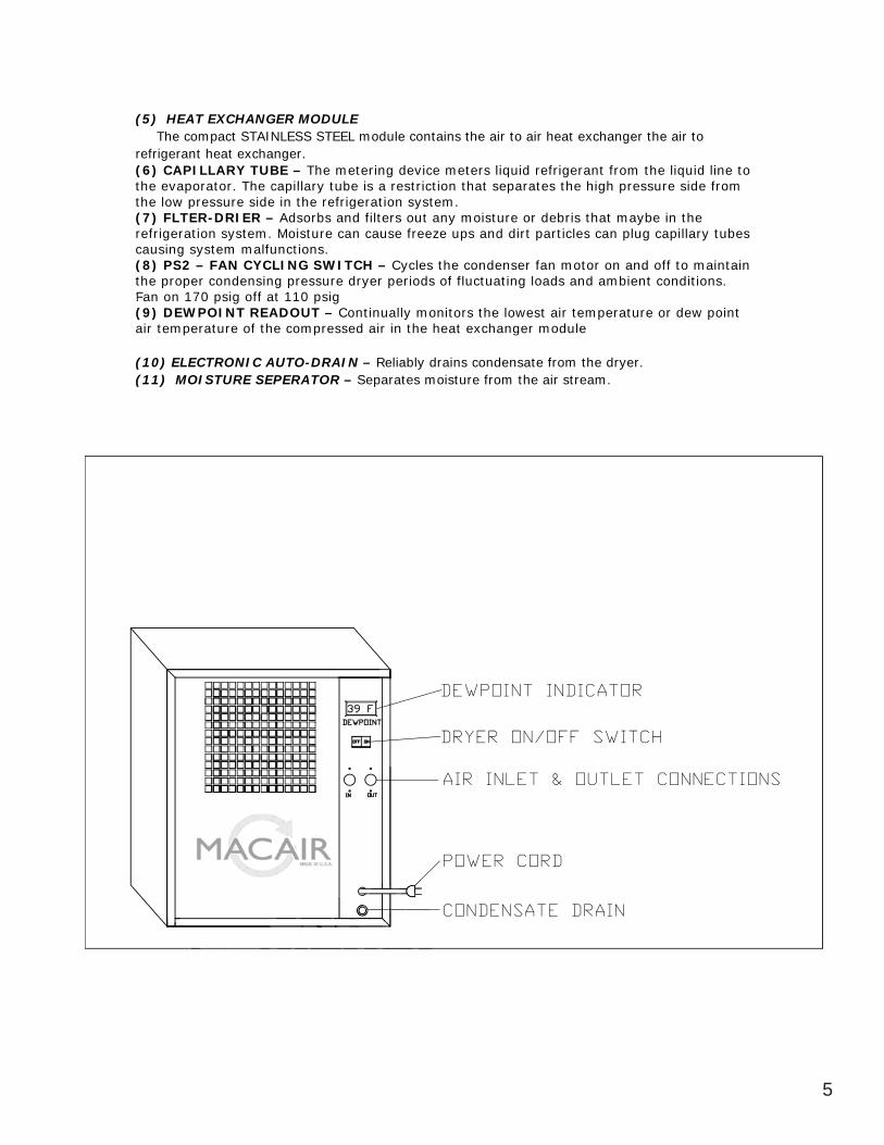
5
(5) HEAT EXCHANGER MODULE The compact STAINLESS STEEL module contains the air to air heat exchanger the air to refrigerant heat exchanger. (6) CAPILLARY TUBE – The metering device meters liquid refrigerant from the liquid line to the evaporator. The capillary tube is a restriction that separates the high pressure side from the low pressure side in the refrigeration system. (7) FLTER-DRIER – Adsorbs and filters out any moisture or debris that maybe in the refrigeration system. Moisture can cause freeze ups and dirt particles can plug capillary tubes causing system malfunctions. (8) PS2 – FAN CYCLING SWITCH – Cycles the condenser fan motor on and off to maintain the proper condensing pressure dryer periods of fluctuating loads and ambient conditions. Fan on 170 psig off at 110 psig (9) DEWPOINT READOUT – Continually monitors the lowest air temperature or dew point air temperature of the compressed air in the heat exchanger module
(10) ELECTRONIC AUTO-DRAIN – Reliably drains condensate from the dryer. (11) MOISTURE SEPERATOR – Separates moisture from the air stream.
evaporthe
syste
(8) PS2 –
ow p(7) FLTErefrigeratcausing s(8) P
pw press
R-Dration
ARY tor. Thure sRIERyste
m
TUBEhe caide in
– Ads. Mois
ger. E – Thpillaryn the r
sorbs
STE
he mety tube
efrigeand
EL mo
eterinis rat
FFanpoproon
opper cFAANN CCYY
lfCunctti
sto
urree cad fiiltter
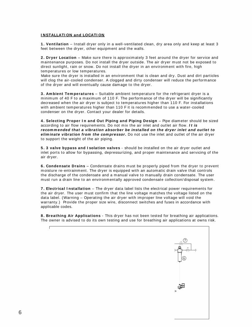
6
INSTALLATION and LOCATION
1. Ventilation – Install dryer only in a well-ventilated clean, dry area only and keep at least 3 feet between the dryer, other equipment and the walls. 2. Dryer Location – Make sure there is approximately 3 feet around the dryer for service and maintenance purposes. Do not install the dryer outside. The air dryer must not be exposed to direct sunlight, rain or snow. Do not install the dryer in an environment with fire, high temperatures or low temperatures. Make sure the dryer is installed in an environment that is clean and dry. Dust and dirt particles will clog the air-cooled condenser. A clogged and dirty condenser will reduce the performance of the dryer and will eventually cause damage to the dryer.
3. Ambient Temperatures – Suitable ambient temperature for the refrigerant dryer is a minimum of 40 F to a maximum of 110 F. The performance of the dryer will be significantly decreased when the air dryer is subject to temperatures higher than 110 F. For installations with ambient temperatures higher than 110 F it is recommended to use a water-cooled condenser on the dryer. Contact your dealer for details. 4. Selecting Proper In and Out Piping and Piping Design – Pipe diameter should be sized according to air flow requirements. Do not mix the air inlet and outlet air flow. It is recommended that a vibration absorber be installed on the dryer inlet and outlet to eliminate vibration from the compressor. Do not use the inlet and outlet of the air dryer to support the weight of the air piping.
5. 3 valve bypass and Isolation valves - should be installed on the air dryer outlet and inlet ports to allow for bypassing, depressurizing, and proper maintenance and servicing of the air dryer.
6. Condensate Drains – Condensate drains must be properly piped from the dryer to prevent moisture re-entrainment. The dryer is equipped with an automatic drain valve that controls the discharge of the condensate and a manual valve to manually drain condensate. The user must run a drain line to an environmentally approved condensate collection/disposal system.
7. Electrical Installation – The dryer data label lists the electrical power requirements for the air dryer. The user must confirm that the line voltage matches the voltage listed on the data label. (Warning – Operating the air dryer with improper line voltage will void the warranty.) Provide the proper size wire, disconnect switches and fuses in accordance with applicable codes.
8. Breathing Air Applications - This dryer has not been tested for breathing air applications. The owner is advised to do its own testing and use for breathing air applications at owns risk.
2.
gure
Make suril
ryemaintendirect stemperaMake
ryer Lonc
sunl
en the catiopurt, ror
Ine drye
on – M
oses. Dn or sn
tall der, oth
Make s
Do n
ryer oher eq
sure tt in
N
only iquipm
her
of thch
loogg teh
thhe ddrryowerw tem
nopoww. DDo
nsttaall t
be h an automatic dre to manually d
condensa
roperly pautomat
manually
piped
e aenance
romn v
ir dryce and
the dry
er outd servi
yer
tlet anicing o
nd of t
th
attee ccollln coonddeen
e thyater
cr to ppreeev
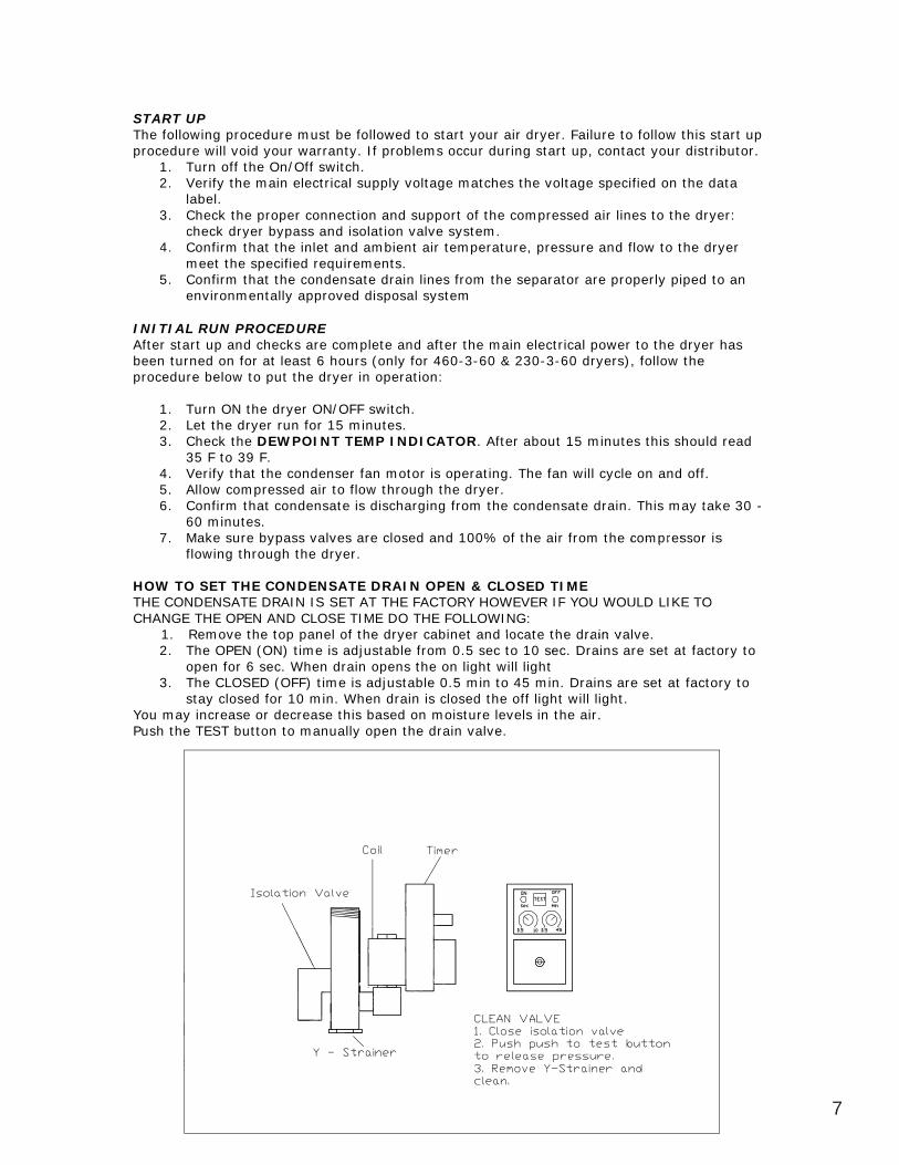
7
START UP The following procedure must be followed to start your air dryer. Failure to follow this start up procedure will void your warranty. If problems occur during start up, contact your distributor.
1. Turn off the On/Off switch. 2. Verify the main electrical supply voltage matches the voltage specified on the data
label. 3. Check the proper connection and support of the compressed air lines to the dryer:
check dryer bypass and isolation valve system. 4. Confirm that the inlet and ambient air temperature, pressure and flow to the dryer
meet the specified requirements. 5. Confirm that the condensate drain lines from the separator are properly piped to an
environmentally approved disposal system
INITIAL RUN PROCEDURE After start up and checks are complete and after the main electrical power to the dryer has been turned on for at least 6 hours (only for 460-3-60 & 230-3-60 dryers), follow the procedure below to put the dryer in operation:
1. Turn ON the dryer ON/OFF switch. 2. Let the dryer run for 15 minutes. 3. Check the DEWPOINT TEMP INDICATOR. After about 15 minutes this should read
35 F to 39 F. 4. Verify that the condenser fan motor is operating. The fan will cycle on and off. 5. Allow compressed air to flow through the dryer. 6. Confirm that condensate is discharging from the condensate drain. This may take 30 -
60 minutes. 7. Make sure bypass valves are closed and 100% of the air from the compressor is
flowing through the dryer.
HOW TO SET THE CONDENSATE DRAIN OPEN & CLOSED TIME THE CONDENSATE DRAIN IS SET AT THE FACTORY HOWEVER IF YOU WOULD LIKE TO CHANGE THE OPEN AND CLOSE TIME DO THE FOLLOWING: 1. Remove the top panel of the dryer cabinet and locate the drain valve.
2. The OPEN (ON) time is adjustable from 0.5 sec to 10 sec. Drains are set at factory to open for 6 sec. When drain opens the on light will light
3. The CLOSED (OFF) time is adjustable 0.5 min to 45 min. Drains are set at factory to stay closed for 10 min. When drain is closed the off light will light.
You may increase or decrease this based on moisture levels in the air. Push the TEST button to manually open the drain valve.
l b
firmmee
5
Cch
4. Com
label.ck
heck
ty the
the pryetha
he Onmain
proper bypassth
r wa/Off s electr
r conns an
t brrantyswitchrical su
ectio
e folloy. If h.
upp
CCoonnffirrmhee speecci
hfe innlet
nt
d issoolnla
atiannd
CLOOWEVER IF YOU WWINd locate the
SED TIMVER IF Y
G: cat
E F YO
the c
OU
compr
D LI
ma
ressor
take
r is
30 -
will lig0 shseecc
dDdrDraainn vval
KKE TTOO
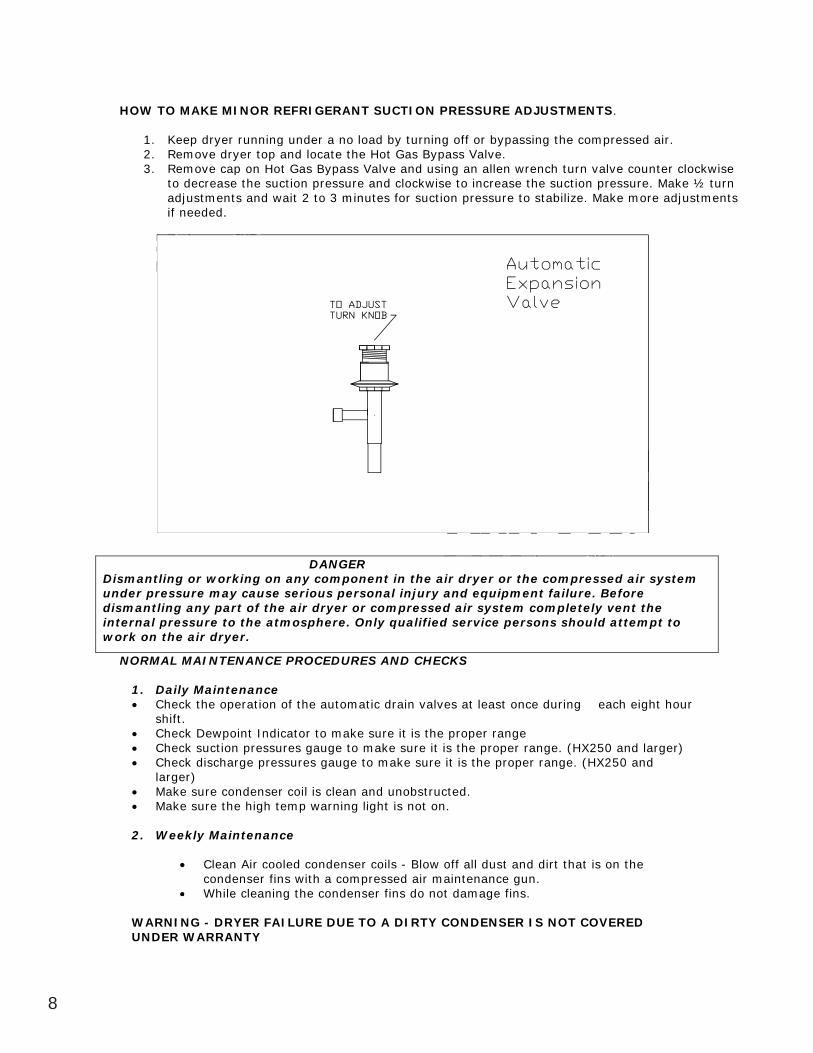
8
HOW TO MAKE MINOR REFRIGERANT SUCTION PRESSURE ADJUSTMENTS.
1. Keep dryer running under a no load by turning off or bypassing the compressed air. 2. Remove dryer top and locate the Hot Gas Bypass Valve. 3. Remove cap on Hot Gas Bypass Valve and using an allen wrench turn valve counter clockwise
to decrease the suction pressure and clockwise to increase the suction pressure. Make ½ turn adjustments and wait 2 to 3 minutes for suction pressure to stabilize. Make more adjustments if needed.
Diagram F
NORMAL MAINTENANCE PROCEDURES AND CHECKS
1. Daily Maintenance Check the operation of the automatic drain valves at least once during each eight hour shift. Check Dewpoint Indicator to make sure it is the proper range Check suction pressures gauge to make sure it is the proper range. (HX250 and larger) Check discharge pressures gauge to make sure it is the proper range. (HX250 and larger) Make sure condenser coil is clean and unobstructed. Make sure the high temp warning light is not on.
2. Weekly Maintenance
Clean Air cooled condenser coils - Blow off all dust and dirt that is on the condenser fins with a compressed air maintenance gun. While cleaning the condenser fins do not damage fins.
WARNING - DRYER FAILURE DUE TO A DIRTY CONDENSER IS NOT COVERED UNDER WARRANTY
DANGER Dismantling or working on any component in the air dryer or the compressed air system under pressure may cause serious personal injury and equipment failure. Before dismantling any part of the air dryer or compressed air system completely vent the internal pressure to the atmosphere. Only qualified service persons should attempt to work on the air dryer.
toadif
to decust
if nee
ove dove ca
reasemented.
dryer tap on e the ss and w
ning top anHot Gsuctiowait
undernd locaGas By
n preto
r a nate typassu
o 3 mmin
dryer orndad i
equuiporr tthhee cco
Clean
ARNING - DRYDER WARR
conWhi
ING - DRR W
lean Ans
le c
ir cooer finanin
nce
oled cs with
the co
ondenh a co
ond
g
nser compre
light
oilssse
RAANNTTYYFAAAILLUURE
densseerr fseinedd
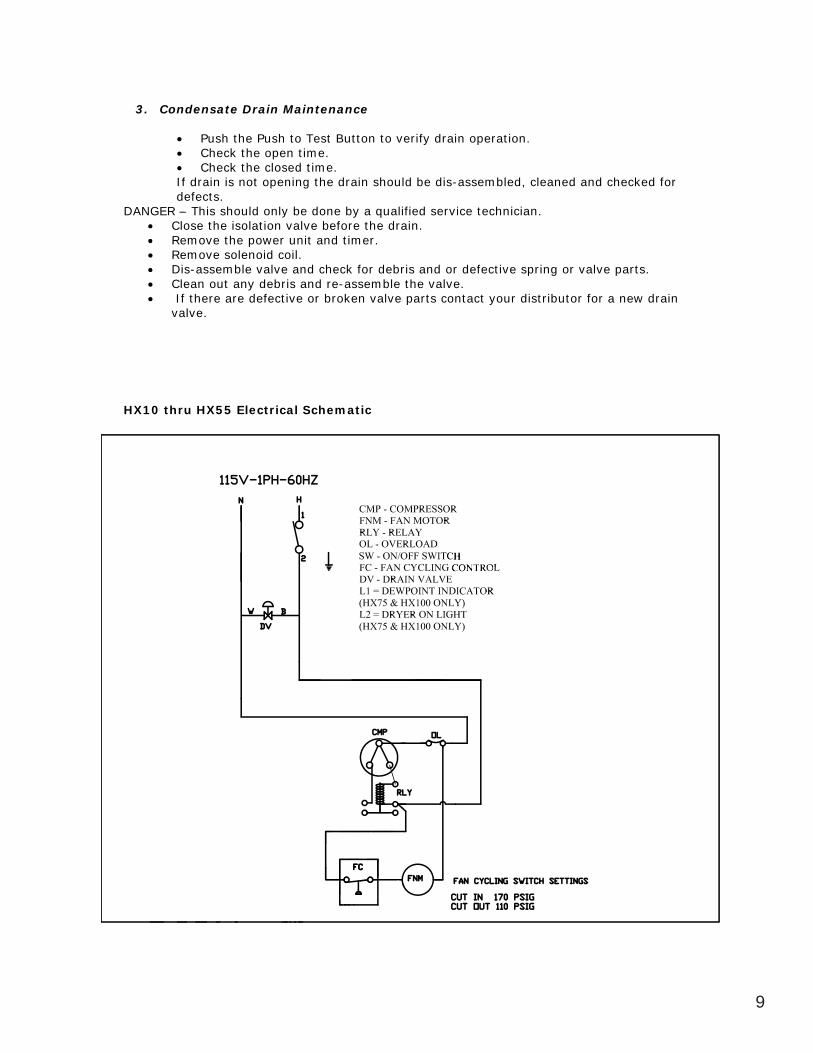
9
3. Condensate Drain Maintenance
Push the Push to Test Button to verify drain operation. Check the open time. Check the closed time.
If drain is not opening the drain should be dis-assembled, cleaned and checked for defects.
DANGER – This should only be done by a qualified service technician. Close the isolation valve before the drain. Remove the power unit and timer. Remove solenoid coil. Dis-assemble valve and check for debris and or defective spring or valve parts. Clean out any debris and re-assemble the valve. If there are defective or broken valve parts contact your distributor for a new drain valve.
HX10 thru HX55 Electrical Schematic
se Rem
DANGER C
If drfe
R – T
ChecCheckain is ts. s shhe i
ck thek the
not o
uld onll
Push openclosedopenin
y b
to Tesn time.d timeng the
est Bu. e.
dr
RReemmmoovovvee tthhee p
laatioonyy vabe ddoonn
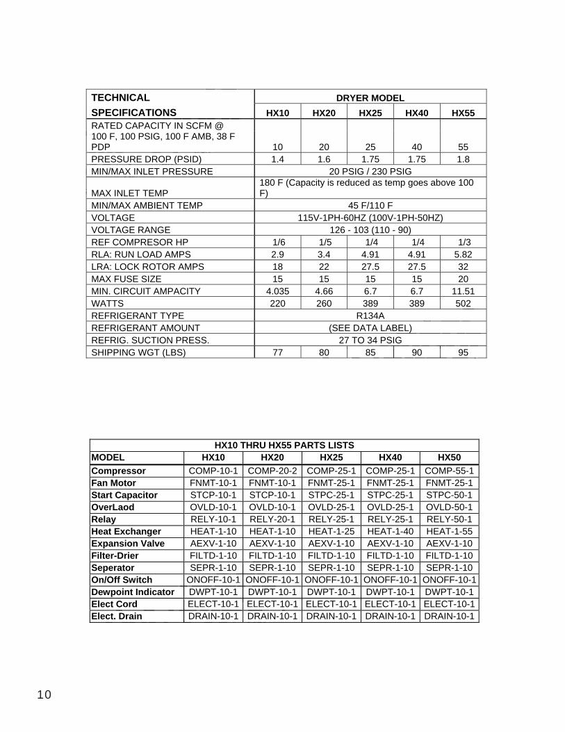
10
TECHNICAL DRYER MODEL SPECIFICATIONS HX10 HX20 HX25 HX40 HX55 RATED CAPACITY IN SCFM @ 100 F, 100 PSIG, 100 F AMB, 38 F PDP 10 20 25 40 55 PRESSURE DROP (PSID) 1.4 1.6 1.75 1.75 1.8 MIN/MAX INLET PRESSURE 20 PSIG / 230 PSIG
MAX INLET TEMP 180 F (Capacity is reduced as temp goes above 100 F)
MIN/MAX AMBIENT TEMP 45 F/110 F VOLTAGE 115V-1PH-60HZ (100V-1PH-50HZ) VOLTAGE RANGE 126 - 103 (110 - 90) REF COMPRESOR HP 1/6 1/5 1/4 1/4 1/3 RLA: RUN LOAD AMPS 2.9 3.4 4.91 4.91 5.82 LRA: LOCK ROTOR AMPS 18 22 27.5 27.5 32 MAX FUSE SIZE 15 15 15 15 20 MIN. CIRCUIT AMPACITY 4.035 4.66 6.7 6.7 11.51 WATTS 220 260 389 389 502 REFRIGERANT TYPE R134A REFRIGERANT AMOUNT (SEE DATA LABEL) REFRIG. SUCTION PRESS. 27 TO 34 PSIG SHIPPING WGT (LBS) 77 80 85 90 95
HX10 THRU HX55 PARTS LISTS MODEL HX10 HX20 HX25 HX40 HX50 Compressor COMP-10-1 COMP-20-2 COMP-25-1 COMP-25-1 COMP-55-1 Fan Motor FNMT-10-1 FNMT-10-1 FNMT-25-1 FNMT-25-1 FNMT-25-1 Start Capacitor STCP-10-1 STCP-10-1 STPC-25-1 STPC-25-1 STPC-50-1 OverLaod OVLD-10-1 OVLD-10-1 OVLD-25-1 OVLD-25-1 OVLD-50-1 Relay RELY-10-1 RELY-20-1 RELY-25-1 RELY-25-1 RELY-50-1 Heat Exchanger HEAT-1-10 HEAT-1-10 HEAT-1-25 HEAT-1-40 HEAT-1-55 Expansion Valve AEXV-1-10 AEXV-1-10 AEXV-1-10 AEXV-1-10 AEXV-1-10 Filter-Drier FILTD-1-10 FILTD-1-10 FILTD-1-10 FILTD-1-10 FILTD-1-10 Seperator SEPR-1-10 SEPR-1-10 SEPR-1-10 SEPR-1-10 SEPR-1-10 On/Off Switch ONOFF-10-1 ONOFF-10-1 ONOFF-10-1 ONOFF-10-1 ONOFF-10-1 Dewpoint Indicator DWPT-10-1 DWPT-10-1 DWPT-10-1 DWPT-10-1 DWPT-10-1 Elect Cord ELECT-10-1 ELECT-10-1 ELECT-10-1 ELECT-10-1 ELECT-10-1 Elect. Drain DRAIN-10-1 DRAIN-10-1 DRAIN-10-1 DRAIN-10-1 DRAIN-10-1
RATED C
REMIN/MAX
100 F, 1PDP PRESSUMIN
ED CAP0 P
ATIOPACIT
SIG,
RO
ONS TY IN
100 F ASCFMF AMB
M @ 38
MMAAX
NNLLEETT PP R
(PPSSIDD)
F
80 85 4 PSIG
BEL) G
90 95
2
Cord ct. DDrain
r DELDR
ONOFDWPTLECT-RAIN-1
F-10-T-10-1 T-10-1
10-1
0 S1 ON DW
ELEDRA
LTSEPRNOFFWPT
CTRAAINN-110
11
MACAIR LIMITED REFRIGERATED AIR DRYER WARRANTY
MACAIR (herein after referred to as the seller) refrigerated air dryers are warranted to be free of defect in materials and workmanship for a limited period of 2 YEARS from the date of shipment from the sellers warehouse to the distributors warehouse or end user (herein after called the buyer) provided the air dryers are applied, installed and maintained in accordance with sellers recommendations listed in the owner’s manual. This warranty applies only to the original owner and is not transferable. The warranty covers materials and labor for the first year and materials only for 2 YEARS from the date of shipment. The air to air, air to refrigerant heat exchangers and the separator on the HX series dryer is warranted to be free of defects for 5 years from the date of shipment from the factory. Normal maintenance items, customer maintained components and labor charges after the first year from the ship date from the seller are not covered by this warranty. The following is not covered by this warranty: Refrigerant leaks after the first 12 months, Condenser cleaning, maintaining the drain valve (Time adjustments and cleaning, auto-drains sticking open or closed due to debris, float drains sticking open or closed) fan motor lubrication, filter element changing and damage in shipping. After the first year from the ship date from the seller, the seller will not be responsible for the following incidental items: service call charges, refrigerant, filter driers, insulation, truck charges, torch charges, recovery/reclaim charges, disposal charges, mileage, miscellaneous fittings, or freight charges. The seller will only allow the amount of labor hours and pay the labor rates that are listed in the MACAIR WARRANTY & SERVICE GUIDELINES. In the event of a warranty issue the buyer must follow the warranty procedures listed in the MACAIR WARRANTY & SERVICE GUIDELINES or the warranty is void. If the buyer purchases replacement parts from a third party, the seller will not be responsible for the cost of the parts. The buyer will be invoiced for the new materials and must return the defective materials to the buyer. Upon inspection of the defective materials and if the materials are deemed defective, the buyer will be credited for the cost of the new materials. The buyer is responsible for all transportation costs of all materials that are shipped to the buyer and to the seller after the initial 12-month period. The seller will not be responsible for any consequential damage, economic loss, extra expense including payment for the loss of time, pay, inconvenience, storage, removal, reinstallation, loss of dryer use, dryer rental expense, lodging, meals, or other travel. The foregoing warranty is exclusive and in lieu of all other warranties, whether written, oral, or statutory, including implied warranties of merchantability or fitness for any particular purpose. This contract shall constitute the entire agreement between Buyer and Seller. All terms contained herein shall be deemed acceptable by the Buyer and The Seller and shall prevail over the terms of the Buyers purchase order. The seller’s liability is limited solely to the repair or replacement of defective products at seller’s option. Under no circumstances shall sell, the sellers distributor or agent be liable for any losses or consequential damages, costs or expenses of any kind incurred by the buyer, whether arising from breach of warranty, negligence or strict liability in tort. The seller makes no warranty or representation of any kind, expressed or implied as to the merchantability or of fitness for a particular purpose with respects to the products. This contract shall be governed and interpreted in accordance with the laws of the State of Michigan. Warranty only applies to equipment sold in the USA and Canada.
be free oda
wionly to the othe first
ate of shafter calleccordancnly to thhe
ree of m
ed th
CAIRdefectent fr
bu se
R (hert in mom theer) proers
R L
rein aftmateria
he selovide
MITE
fter refals and
ers w
ED R
eferrd war
ofeff
riggeerray
anyeeaar a
gnnadall oowwn
rrecoome
md theee a
araiehh
terials ant of t
tha
al damage, econoence, storage
e net are shi
mage, ece, sto
ls and new m
ped
urn thif theateriato th
c
the che defe mat
ls. Thee buye
ost offectiveterials he buy
er an
urchaf the e
are yer is
ases
heerr wot
ahear
err tra,
av reemmoovva
losss,, ext
d to tthhee
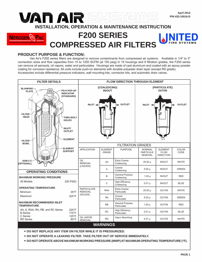
PAGE 1
WARNINGSDO NOT REPLACE ANY ITEM ON FILTER WHILE IT IS PRESSURIZED.DO NOT OPERATE A LEAKING FILTER. TAKE FILTER OUT OF SERVICE IMMEDIATELY.DO NOT OPERATE ABOVE MAXIMUM WORKING PRESSURE (MWP) AT MAXIMUM OPERATING TEMPERATURE (°F).
••
•
(COALESCING)IN/OUT
(PARTICULATE)OUT/IN
April 2012P/N 432-10016-D
FILTER DETAILS FLOW DIRECTION THROUGH ELEMENT
OUTLET INLET OUTLET INLET
FILTERBOWL
FILTERHEAD
ELEMENT SUPPORT
ELEMENT
INLET/OUTLET
PD-6 POP-UP INDICATOR(STANDARD)
THRU-BOLT HOLES
BLANKING PLATE
PRODUCT PURPOSE & FUNCTION: Van Air's F200 series filters are designed to remove contaminants from compressed air systems. Available in 1/4" to 3" connection sizes and flow capacities from 15 to 1250 SCFM (at 100 psig) in 15 housings and 9 filtration grades, the F200 series can remove oil aerosols, oil vapors, water and particulates. Housings are made of cast aluminum and coated with an epoxy powder coating for corrosion resistance. All units include push-on elements with durable polyester drain layer (except RD grade). Accessories include differential pressure indicators, wall mounting kits, connector kits, and automatic drain valves.
OPERATING CONDITIONSMAXIMUM WORKING PRESSUREAll Models
OPERATING TEMPERATUREMinimumMaximum
MAXIMUM RECOMMENDED INLET TEMPERATUREAA, A, RAA, RA, RB, and RC SeriesB SeriesC SeriesRD Series
250 PSIG
35°F225°F
225°F175°F125°F80°F
ADM-2-2(OPTIONAL)
INSTALLATION, OPERATION & MAINTENANCE INSTRUCTION
F200 SERIESCOMPRESSED AIR FILTERS
FILTRATION GRADESAPPLICATION ELEMENT
GRADEPURPOSE NOMINAL
PARTICULE REMOVAL
ELEMENT FLOW
DIRECTION
COLOR CODE
OIL REMOVAL(LIQUIDS)
AA Extra CoarseCoalescing 25.00 μ IN/OUT WHITE
A CoarseCoalescing 5.00 μ IN/OUT GREEN
B General PurposeCoalescing 1.00 μ IN/OUT RED
C High EfficiencyCoalescing 0.01 μ IN/OUT BLUE
PARTICULATEREMOVAL(SOLIDS)
RAA Extra CoarseParticulate 25.00 μ OUT/IN WHITE
RA CoarseParticulate 5.00 μ OUT/IN GREEN
RB General PurposeParticulate 1.00 μ OUT/IN RED
RC High EfficiencyParticulate 0.01 μ OUT/IN BLUE
OIL VAPORREMOVAL RD Vapor Absorbing 0.01 μ OUT/IN WHITE
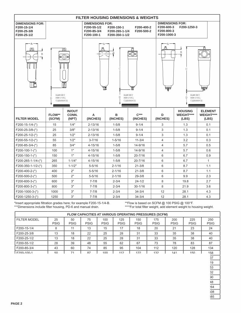
PAGE 2
FILTER HOUSING DIMENSIONS & WEIGHTSDIMENSIONS FOR:F200-55-1/2F200-85-3/4F200-100-1
F200-150-1 F200-265-1-1/4F200-350-1-1/2
DIMENSIONS FOR:F200-600-3 F200-1250-3F200-800-3F200-1000-3
DIMENSIONS FOR:F200-15-1/4F200-25-3/8F200-25-1/2
*Insert appropriate filtration grades here; for example F200-15-1/4-B.***Dimensions include filter housing, PD-6 and manual drain.
**Flow is based on SCFM @ 100 PSIG @ 100°F.****For total filter weight, add element weight to housing weight.
F200-400-2F200-500-2
FILTER MODELFLOW** (SCFM)
IN/OUT CONN. (NPT)
A (INCHES)
B (INCHES)
C*** (INCHES)
D (INCHES)
HOUSING WEIGHT****
(LBS)
ELEMENT WEIGHT****
(LBS)
F200-15-1/4-(*) 15 1/4" 2-13/16 1-5/8 9-1/4 3 1.3 0.1F200-25-3/8-(*) 25 3/8" 2-13/16 1-5/8 9-1/4 3 1.3 0.1F200-25-1/2-(*) 25 1/2" 2-13/16 1-5/8 9-1/4 3 1.3 0.1F200-55-1/2-(*) 55 1/2" 3-7/16 1-5/16 11-3/4 4 3.2 0.3F200-85-3/4-(*) 85 3/4" 4-15/16 1-5/8 14-9/16 4 5.7 0.5F200-100-1-(*) 100 1" 4-15/16 1-5/8 14-9/16 4 5.7 0.6F200-150-1-(*) 150 1" 4-15/16 1-5/8 20-7/16 6 6.7 0.9F200-265-1-1/4-(*) 265 1-1/4" 4-15/16 1-5/8 20-7/16 6 6.7 1F200-350-1-1/2-(*) 350 1-1/2" 5-5/16 2-1/16 21-3/8 6 8.7 1.1F200-400-2-(*) 400 2" 5-5/16 2-1/16 21-3/8 6 8.7 1.1F200-500-2-(*) 500 2" 5-5/16 2-1/16 29-3/8 6 9.9 2.3F200-600-3-(*) 600 3" 7-7/8 2-3/4 24-1/2 8 19.8 2.7F200-800-3-(*) 800 3" 7-7/8 2-3/4 30-1/16 8 21.9 3.6F200-1000-3-(*) 1000 3" 7-7/8 2-3/4 34-3/4 12 28.1 4.3F200-1250-3-(*) 1250 3" 7-7/8 2-3/4 34-3/4 12 28.1 4.3
FLOW CAPACITIES AT VARIOUS OPERATING PRESSURES (SCFM)FILTER MODEL 25
PSIG50
PSIG75
PSIG100
PSIG125
PSIG150
PSIG175
PSIG200
PSIG225
PSIG250
PSIGF200-15-1/4 8 11 13 15 17 18 20 21 23 24F200-25-3/8 13 18 22 25 28 31 33 35 38 40F200-25-1/2 13 18 22 25 28 31 33 35 38 40F200-55-1/2 28 39 48 55 62 67 73 78 83 87F200-85-3/4 43 60 74 85 95 104 112 120 128 134F200-100-1 50 71 87 100 112 122 132 141 150 158F200-150-1 75 107 131 150 168 183 198 212 225 237F200-265-1-1/4 133 188 231 265 297 323 350 374 398 419F200-350-1-1/2 175 249 305 350 392 427 462 494 525 553F200-400-2 200 284 348 400 448 488 528 564 600 632F200-500-2 250 355 435 500 560 610 660 705 750 790F200-600-3 300 426 522 600 672 732 792 846 900 948F200-800-3 400 568 696 800 896 976 1056 1128 1200 1264F200-1000-3 500 710 870 1000 1120 1220 1320 1410 1500 1508F200-1250-3 625 888 1088 1250 1400 1525 1650 1763 1875 1885
A
B
C
D
A
B
C
D D
C
B
A
ELEMENTREMOVALCLEARANCE
ELEMENTREMOVALCLEARANCE
ELEMENTREMOVALCLEARANCE
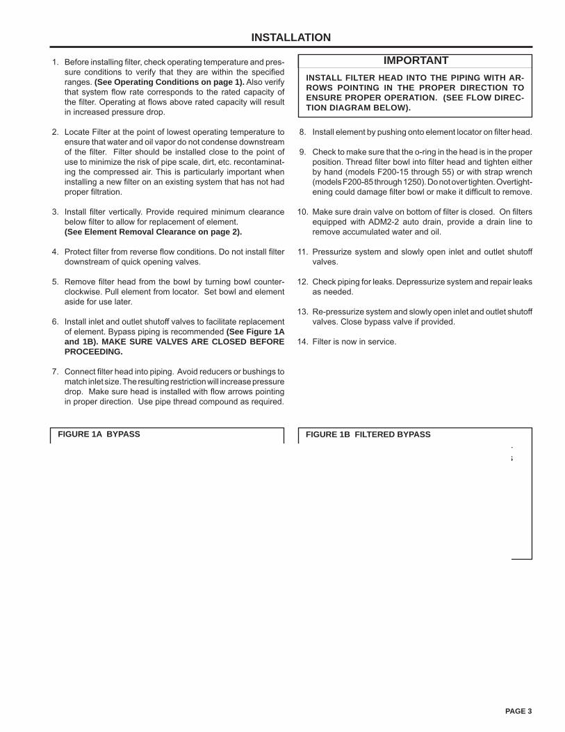
PAGE 3
INSTALLATION
FIGURE 1A BYPASS
INLET SHUTOFF
VALVE
BYPASS VALVE
FILTER
OUTLET SHUTOFF VALVE
FIGURE 1C FILTERS MANIFOLDED WITH CONNECTOR KIT
COALESC-ING FILTER (HIGHER EF-FICIENCY)
PARTICULATEFILTER
(LOWER EF-FICIENCY)
FIGURE 1B FILTERED BYPASS
INLET SHUTOFF
VALVE
OUTLET SHUTOFF VALVEFILTER
INLET BYPASS
VALVE
OUTLET BYPASS VALVE
BYPASS FILTER
Before installing filter, check operating temperature and pres-sure conditions to verify that they are within the specified ranges. (See Operating Conditions on page 1). Also verify that system flow rate corresponds to the rated capacity of the filter. Operating at flows above rated capacity will result in increased pressure drop.
Locate Filter at the point of lowest operating temperature to ensure that water and oil vapor do not condense downstream of the filter. Filter should be installed close to the point of use to minimize the risk of pipe scale, dirt, etc. recontaminat-ing the compressed air. This is particularly important when installing a new filter on an existing system that has not had proper filtration.
Install filter vertically. Provide required minimum clearance below filter to allow for replacement of element.(See Element Removal Clearance on page 2).
Protect filter from reverse flow conditions. Do not install filter downstream of quick opening valves.
Remove filter head from the bowl by turning bowl counter-clockwise. Pull element from locator. Set bowl and element aside for use later.
Install inlet and outlet shutoff valves to facilitate replacement of element. Bypass piping is recommended (See Figure 1A and 1B). MAKE SURE VALVES ARE CLOSED BEFORE PROCEEDING.
Connect filter head into piping. Avoid reducers or bushings to match inlet size. The resulting restriction will increase pressure drop. Make sure head is installed with flow arrows pointing in proper direction. Use pipe thread compound as required.
1.
2.
3.
4.
5.
6.
7.
IMPORTANTINSTALL FILTER HEAD INTO THE PIPING WITH AR-ROWS POINTING IN THE PROPER DIRECTION TO ENSURE PROPER OPERATION. (SEE FLOW DIREC-TION DIAGRAM BELOW).
Install element by pushing onto element locator on filter head.
Check to make sure that the o-ring in the head is in the proper position. Thread filter bowl into filter head and tighten either by hand (models F200-15 through 55) or with strap wrench (models F200-85 through 1250). Do not over tighten. Overtight-ening could damage filter bowl or make it difficult to remove.
Make sure drain valve on bottom of filter is closed. On filters equipped with ADM2-2 auto drain, provide a drain line to remove accumulated water and oil.
Pressurize system and slowly open inlet and outlet shutoff valves.
Check piping for leaks. Depressurize system and repair leaks as needed.
Re-pressurize system and slowly open inlet and outlet shutoff valves. Close bypass valve if provided.
Filter is now in service.
8.
9.
10.
11.
12.
13.
14.
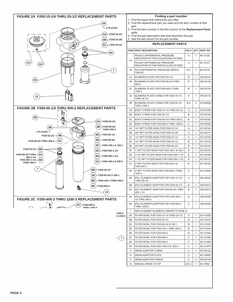
PAGE 4
Find the figure that references your filter.Find the replacement part you need and the item number of that part.Find the item number in the first column of the Replacement Parts table.Find the part description that best describes the part.See the last column for the part number.
FIGURE 2A F200-15-1/4 THRU 25-1/2 REPLACEMENT PARTS
2 PLACES
4A
5A
7
8A
12
7
FIGURE 2B F200-55-1/2 THRU 500-2 REPLACEMENT PARTS
FIGURE 2C F200-600-3 THRU 1250-3 REPLACEMENT PARTS
1A
7
1B
9
10
11 4 PLACES
F200-15-1/4
5B F200-25-3/8
5C F200-25-1/2
6A
2C
8FF200-600-3
8GF200-800-3
8HF200-1000-3& 1250-3
4D
3B2 PLACES
5KF200-600-3 THRU 1250-3
6E F200-600-3 THRU 1250-3
F200-600-3 THRU 1250-3
1B
3B2 PLACES
4B
4C
6BF200-55-1/2
6CF200-85-3/4 THRU 265-1-1/4
6DF200-350-1-1/2 THRU 500-2
F200-55-1/2
F200-85-3/4 THRU 500-2
F200-100-1 & 150-1
F200-85-3/4
5D F200-55-1/2
5E
5F
5G F200-265-1-1/4
5H F200-350-1-1/2
5J F200-400-2 & 500-2
2A F200-55-1/2
2B F200-85-3/4 THRU 500-2
8B F200-55-1/2
8C F200-85-3/4 & 100-1
8D F200-150-1 THRU 400-2
8E F200-500-2
1.2.
3.
4.5.
Finding a part number
12
12
3A
REPLACEMENT PARTS
ITEM PART DESCRIPTION FIG 2- QTY PART NO.
1A
PD-6A-C DIFFERENTIAL PRESSURE INDICATOR KIT FOR COALESCING FILTERS
A 1 84-10126
PD-6A-P DIFFERENTIAL PRESSURE INDICATOR KIT FOR PARTICULATE FILTERS
A 1 84-10127
1B PD-6 DIFFERENTIAL PRESSURE INDICA-TOR KIT
B,C 1 84-10125
2A BLANKING PLATE FOR F200-55-1/2 B 1 326-00110
2B BLANKING PLATE FOR F200-85-3/4 THRU 500-2
B 1 326-00120
2C BLANKING PLATE FOR F200-600-3 THRU 1250-3
B 1 326-00130
3A BLANKING PLATE O-RING FOR F200-15-1/4 THRU 25-1/2
A 1 475-00110
3B BLANKING PLATE O-RING FOR F200-55-1/2 THRU 1250-3
B,C 2 475-00006
4A BODY O-RING FOR F200-15-1/4 THRU 25-1/2 A 2 475-01000
4B BODY O-RING FOR F200-55-1/2 B 1 475-00146
4C BODY O-RING FOR F200-85-3/4 THRU 500-2 B 1 475-00242
4D BODY O-RING FOR F200-600-3 THRU 1250-3 C 1 475-00362
5A 1/4" NPT FILTER HEAD FOR F200-15-1/4 A 1 201-00100
5B 3/8" NPT FILTER HEAD FOR F200-25-3/8 A 1 201-00110
5C 1/2" NPT FILTER HEAD FOR F200-25-1/2 A 1 201-00120
5D 1/2" NPT FILTER HEAD FOR F200-55-1/2 B 1 201-00130
5E 3/4" NPT FILTER HEAD FOR F200-85-3/4 B 1 201-00140
5F 1" NPT FILTER HEAD FOR F200-100-1 & 150-1 B 1 201-00150
5G 1-1/4" NPT FILTER HEAD FOR F200-265-1-1/4 B 1 201-00160
5H 1-1/2" NPT FILTER HEAD FOR F200-350-1-1/2 B 1 201-00170
5J 2" NPT FILTER HEAD FOR F200-400-2 & F200-500-2
B 1 201-00180
5K 3" NPT FILTER HEAD FOR F200-600-3 THRU 1250-3
C 1 201-00200
6A EPL1 ELEMENT ADAPTOR FOR F200-15-1/4 THRU 25-1/2
A 1 326-00005
6B EPL2 ELEMENT ADAPTOR FOR F200-55-1/2 B 1 326-00010
6C EPL3 ELEMENT ADAPTOR F200-85-3/4 THRU 265-1-1/4
B 1 326-00015
6D EPL4 ELEMENT ADAPTOR FOR F200-350-1-1/2 THRU 500-2
B 1 326-00020
6E EPL5 ELEMENT ADAPTOR FOR F200-600-3 THRU 1250-3
C 1 326-00025
7 REPLACEMENT ELEMENTS (REFER TO PAGE 5)
8A FILTER BOWL FOR F200-15-1/4 THRU 25-1/2 A 1 201-01000
8B FILTER BOWL FOR F200-55-1/2 B 1 201-01010
8C FILTER BOWL FOR F200-85-3/4 & 100-1 B 1 201-01020
8D FILTER BOWL FOR F200-150-1 THRU 400-2 B 1 201-01030
8E FILTER BOWL FOR F200-500-2 B 1 201-01040
8F FILTER BOWL FOR F200-600-3 C 1 201-01050
8G FILTER BOWL FOR F200-800-3 C 1 201-01060
8H FILTER BOWL FOR F200-1000-3 & 1250-3 C 1 201-01070
9 DRAIN ADAPTOR O-RING C 1 475-00142
10 DRAIN ADAPTOR PLATE C 1 261-00006
11 DRAIN ADAPTOR SCREW C 4 460-00100
12 MANUAL DRAIN 1/4" KIT A,B, C 1 84-10852
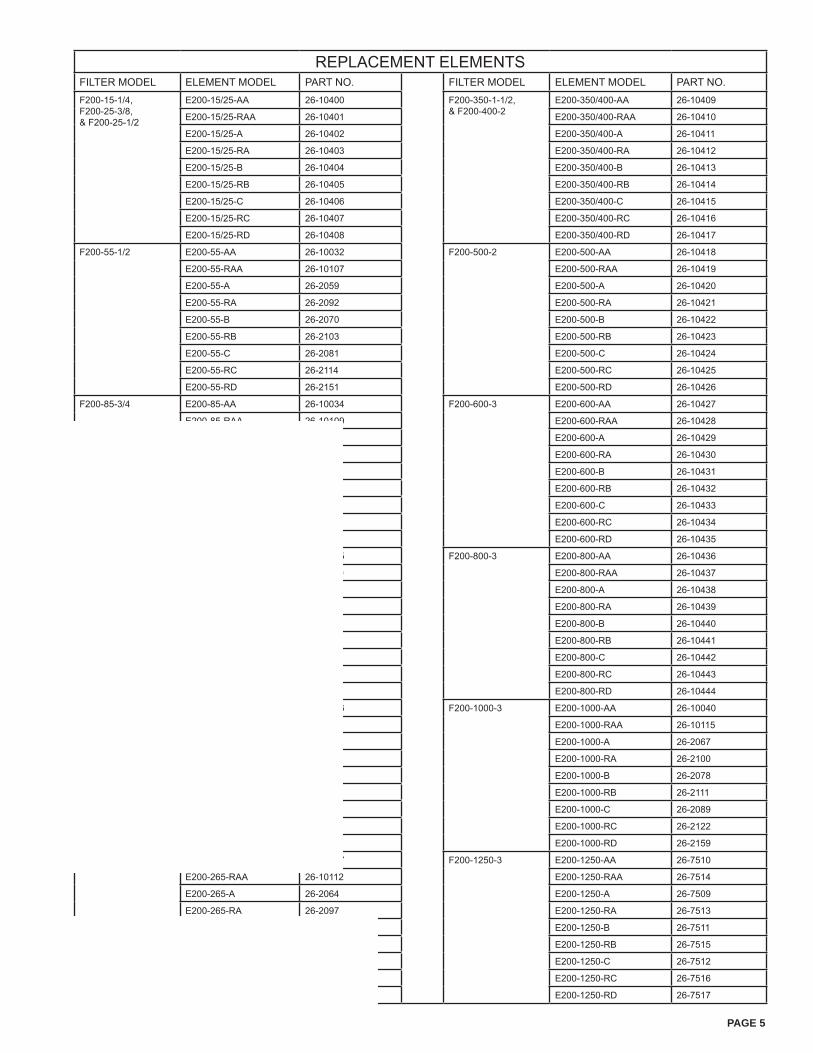
PAGE 5
REPLACEMENT ELEMENTSFILTER MODEL ELEMENT MODEL PART NO. FILTER MODEL ELEMENT MODEL PART NO.F200-15-1/4,F200-25-3/8,& F200-25-1/2
E200-15/25-AA 26-10400 F200-350-1-1/2,& F200-400-2
E200-350/400-AA 26-10409
E200-15/25-RAA 26-10401 E200-350/400-RAA 26-10410
E200-15/25-A 26-10402 E200-350/400-A 26-10411
E200-15/25-RA 26-10403 E200-350/400-RA 26-10412
E200-15/25-B 26-10404 E200-350/400-B 26-10413
E200-15/25-RB 26-10405 E200-350/400-RB 26-10414
E200-15/25-C 26-10406 E200-350/400-C 26-10415
E200-15/25-RC 26-10407 E200-350/400-RC 26-10416
E200-15/25-RD 26-10408 E200-350/400-RD 26-10417
F200-55-1/2 E200-55-AA 26-10032 F200-500-2 E200-500-AA 26-10418
E200-55-RAA 26-10107 E200-500-RAA 26-10419
E200-55-A 26-2059 E200-500-A 26-10420
E200-55-RA 26-2092 E200-500-RA 26-10421
E200-55-B 26-2070 E200-500-B 26-10422
E200-55-RB 26-2103 E200-500-RB 26-10423
E200-55-C 26-2081 E200-500-C 26-10424
E200-55-RC 26-2114 E200-500-RC 26-10425
E200-55-RD 26-2151 E200-500-RD 26-10426
F200-85-3/4 E200-85-AA 26-10034 F200-600-3 E200-600-AA 26-10427
E200-85-RAA 26-10109 E200-600-RAA 26-10428
E200-85-A 26-2061 E200-600-A 26-10429
E200-85-RA 26-2094 E200-600-RA 26-10430
E200-85-B 26-2072 E200-600-B 26-10431
E200-85-RB 26-2105 E200-600-RB 26-10432
E200-85-C 26-2083 E200-600-C 26-10433
E200-85-RC 26-2116 E200-600-RC 26-10434
E200-85-RD 26-2153 E200-600-RD 26-10435
F200-100-1 E200-100-AA 26-10035 F200-800-3 E200-800-AA 26-10436
E200-100-RAA 26-10110 E200-800-RAA 26-10437
E200-100-A 26-2062 E200-800-A 26-10438
E200-100-RA 26-2095 E200-800-RA 26-10439
E200-100-B 26-2073 E200-800-B 26-10440
E200-100-RB 26-2106 E200-800-RB 26-10441
E200-100-C 26-2084 E200-800-C 26-10442
E200-100-RC 26-2117 E200-800-RC 26-10443
E200-100-RD 26-2154 E200-800-RD 26-10444
F200-150-1 E200-150-AA 26-10036 F200-1000-3 E200-1000-AA 26-10040
E200-150-RAA 26-10111 E200-1000-RAA 26-10115
E200-150-A 26-2063 E200-1000-A 26-2067
E200-150-RA 26-2096 E200-1000-RA 26-2100
E200-150-B 26-2074 E200-1000-B 26-2078
E200-150-RB 26-2107 E200-1000-RB 26-2111
E200-150-C 26-2085 E200-1000-C 26-2089
E200-150-RC 26-2118 E200-1000-RC 26-2122
E200-150-RD 26-2155 E200-1000-RD 26-2159
F200-265-1-1/4 E200-265-AA 26-10037 F200-1250-3 E200-1250-AA 26-7510
E200-265-RAA 26-10112 E200-1250-RAA 26-7514
E200-265-A 26-2064 E200-1250-A 26-7509
E200-265-RA 26-2097 E200-1250-RA 26-7513
E200-265-B 26-2075 E200-1250-B 26-7511
E200-265-RB 26-2108 E200-1250-RB 26-7515
E200-265-C 26-2086 E200-1250-C 26-7512
E200-265-RC 26-2119 E200-1250-RC 26-7516
E200-265-RD 26-2156 E200-1250-RD 26-7517
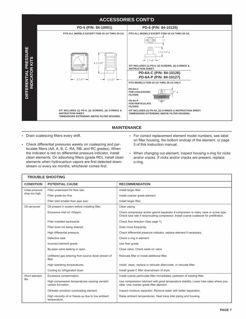
PAGE 7
2-1/8" 2-1/8"
3-3/8"
2-1/4"
2-5/8"
1-1/2"
1/2"
1"
1-11/16"
1-7/8"
DIF
FER
ENTI
AL
PRES
SUR
EIN
DIC
ATO
R K
ITS
PD-5 (P/N: 84-10001) PD-6 (P/N: 84-10125)
KIT INCLUDES (1) PD-6, (2) SCREWS, (4) O-RINGS & INSTRUCTION SHEET.
FITS ALL MODELS EXCEPT F200-15-1/4 THRU 25-1/2. FITS ALL MODELS EXCEPT F200-15-1/4 THRU 25-1/2.
ACCESSORIES CONT'D
MAINTENANCE
Drain coalescing filters every shift.
Check differential pressures weekly on coalescing and par-ticulate filters (AA, A, B, C, RA, RB, and RC grades). When the indicator is red on differential pressure indicator, install clean elements. On adsorbing filters (grade RD), install clean elements when hydrocarbon vapors are first detected down-stream or every six months, whichever comes first.
•
•
For correct replacement element model numbers, see label on filter housing, the bottom endcap of the element, or page 5 of this instruction manual.
When changing out element, inspect housing o-ring for nicks and/or cracks. If nicks and/or cracks are present, replace o-ring.
•
•
PD-6A-C (P/N: 84-10126)PD-6A-P (P/N: 84-10127)
FITS MODELS F200-15-1/4 THRU 25-1/2 ONLY.
PD-6A-CFOR COALESCING FILTERS
PD-6A-PFOR PARTICULATE FILTERS
KIT INCLUDES (1) PD-5, (2) SCREWS, (4) O-RINGS & INSTRUCTION SHEET.*DIMENSIONS EXTENDING ABOVE FILTER HOUSING.
KIT INCLUDES (1) PD-6A, (2) O-RINGS & INSTRUCTION SHEET.*DIMENSIONS EXTENDING ABOVE FILTER HOUSING.
*
*
*
TROUBLE SHOOTING
CONDITION POTENTIAL CAUSE RECOMMENDATION
Initial pressure drop too high
Filter undersized for flow rate. Install larger filter.
Filter grade too fine. Install coarser grade element.
Filter inlet smaller than pipe size. Install larger filter.
Oil carryover Oil present in system before installing filter. Clean piping.
Excessive inlet oil >50ppm. Check compressor and/or gas/oil separator if compressor is rotary vane or screw type. Check lube rate if reciprocating compressor. Install coarse coalescer for prefiltration.
Filter installed backwards. Check flow direction (See page 1).
Filter bowl not being drained. Drain more frequently.
High differential pressure. Check differential pressure indicator, replace element if necessary.
Defective seal. Check o-ring in element.
Incorrect element grade. Use finer grade.
By-pass valve leaking or open. Close valve. Check seals on valve
Unfiltered gas entering from source down stream of filter.
Relocate filter or install additional filter.
High operating temperatures. Install, clean, replace or relocate aftercooler, or relocate filter.
Cooling by refrigerated dryer. Install grade C filter downstream of dryer.
Short element life
Excessive contamination. Install coarse particulate filter immediately upstream of existing filter.
High compression temperatures causing varnish/carbon formation.
Use compression lubricant with good temperature stability. Lower lube rates where pos-sible. Use coarser grade filter element.
Oil/water emulsion overloading element. Inspect moisture separator. Remove water with better separation.
High viscosity oil or freeze-up due to low ambient temperature.
Raise ambient temperatures. Heat trace inlet piping and housing.
PAGE 8
2950 Mechanic StreetLake City, PA 16423-2095
Phone: 800-840-9906Fax: 814-774-3482
www.vanairsystems.com
AIR AND OIL UNDER PRESSURE WILL CAUSE SEVERE PERSONAL INJURY OR DEATH.SHUT DOWN COMPRESSOR AND RELIEVE SYSTEM OF ALL PRESSURE BEFORE REMOVING VALVES, CAPS, PLUGS, FITTINGS, BOLTS AND FILTERs.
DANGER WARNING
READ THE OPERATOR'S MANUAL BEFORE STARTING OR SERVICING THIS UNIT. FAILURE TO ADHERE TO INSTRUCTIONS CAN RESULT IN SEVERE PERSONAL INJURY OR DEATH. REPLACEMENT MANUALS CAN BE OBTAINED BY CONTACTING THE MANUFACTURER.
SAFETY PRECAUTIONSSafety is everybody's business and is based on your use of good common sense. All situations or circumstances cannot always be predicted and covered by established rules. Therefore, use your past experience, watch out for safety hazards and be cautious.

Nitrogen Analyzer
O P E R A T I N G M A N U A L &
I N S T R U C T I O N S F O R U S E
R 2 1 7 P 6 5 , R 2 1 7 P 6 6 , R 2 1 7 P 6 7
R217M65 Rev. A
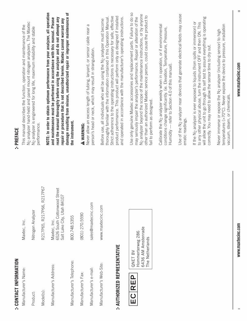
iiww
w.m
axte
cinc
.com
iiiww
w.m
axte
cinc
.com
CON
TACT
INFO
RMAT
ION
Man
ufac
ture
r’s N
ame:
M
axte
c, In
c.
Pro
duct
: N
itrog
en A
naly
zer
Mod
el(s
):
R21
7P65
, R21
7P66
, R21
7P67
Man
ufac
ture
r’s A
ddre
ss:
Max
tec,
Inc.
65
26 S
outh
Cot
tonw
ood
Stre
et
Salt
Lake
City
, Uta
h 84
107
Man
ufac
ture
r’s T
elep
hone
: 80
0.74
8.53
55
Man
ufac
ture
r’s F
ax:
(801
) 27
0.55
90
Man
ufac
ture
r’s e
-mai
l: sa
les@
max
teci
nc.c
om
Man
ufac
ture
r’s W
eb-S
ite:
ww
w.m
axte
cinc
.com
AU
THOR
IZED
REP
RESE
NTA
TIVE
PRE
FACE
This
man
ual d
escr
ibes
the
func
tion,
ope
ratio
n an
d m
aint
enan
ce o
f the
N
2 an
alyz
er h
and-
held
and
pan
el m
ount
nitr
ogen
ana
lyze
rs. T
he M
axte
c N
2 an
alyz
er is
eng
inee
red
for
long
life
, max
imum
rel
iabi
lity
and
stab
le
perf
orm
ance
.
NOT
E: In
ord
er to
obt
ain
optim
um p
erfo
rman
ce fr
om y
our
anal
yzer
, all
oper
atio
n an
d m
aint
enan
ce m
ust b
e pe
rfor
med
in a
ccor
danc
e w
ith th
is m
anua
l. Pl
ease
re
ad th
e m
anua
l tho
roug
hly
befo
re u
sing
the
anal
yzer
and
do
not a
ttem
pt a
ny
repa
ir o
r pr
oced
ure
that
is n
ot d
escr
ibed
her
ein.
Max
tec
cann
ot w
arra
nt a
ny
dam
age
resu
lting
from
mis
use,
una
utho
rize
d re
pair
or
impr
oper
mai
nten
ance
of
the
inst
rum
ent.
!W
ARN
ING:
Nev
er a
llow
an
exce
ss le
ngth
of t
ubin
g, la
nyar
d, o
r se
nsor
cab
le n
ear
a pe
rson
’s h
ead
or n
eck,
whi
ch m
ay r
esul
t in
stra
ngul
atio
n.
Bef
ore
use,
all
indi
vidu
als
who
will
be
usin
g th
e N
2 an
alyz
er m
ust b
ecom
e th
orou
ghly
fam
iliar
with
the
info
rmat
ion
cont
aine
d in
this
Ope
ratio
n M
anua
l. St
rict a
dher
ence
to th
e op
erat
ing
inst
ruct
ions
is n
eces
sary
for
safe
, effe
ctiv
e pr
oduc
t per
form
ance
. Thi
s pr
oduc
t will
per
form
onl
y as
des
igne
d if
inst
alle
d an
d op
erat
ed in
acc
orda
nce
with
the
man
ufac
ture
r’s o
pera
ting
inst
ruct
ions
.
Use
onl
y ge
nuin
e M
axte
c ac
cess
orie
s an
d re
plac
emen
t par
ts. F
ailu
re to
do
so
may
ser
ious
ly im
pair
the
anal
yzer
’s p
erfo
rman
ce. R
epai
r or
alte
ratio
n of
the
N2
anal
yzer
bey
ond
the
scop
e of
the
mai
nten
ance
inst
ruct
ions
, or
by a
nyon
e ot
her
than
an
auth
oriz
ed M
axte
c se
rvic
e pe
rson
, cou
ld c
ause
the
prod
uct t
o fa
il to
per
form
as
desi
gned
.
Cal
ibra
te th
e N
2 an
alyz
er w
eekl
y w
hen
in o
pera
tion,
or
if en
viro
nmen
tal
cond
ition
s ch
ange
sig
nific
antly
. (ie
. Ele
vatio
n, T
empe
ratu
re, P
ress
ure,
H
umid
ity —
ref
er to
Sec
tion
4.0
of th
is m
anua
l).
Use
of t
he N
2 an
alyz
er n
ear
devi
ces
that
gen
erat
e el
ectr
ical
fiel
ds m
ay c
ause
er
ratic
rea
ding
s.
If th
e N
2 an
alyz
er is
eve
r ex
pose
d to
liqu
ids
(fro
m s
pills
or
imm
ersi
on)
or
to a
ny o
ther
phy
sica
l abu
se, t
urn
the
inst
rum
ent O
FF a
nd th
en O
N. T
his
will
allo
w th
e un
it to
go
thro
ugh
its s
elf t
est t
o as
sure
eve
ryth
ing
is o
pera
ting
corr
ectly
. You
may
nee
d to
allo
w th
e se
nsor
tim
e to
dry
out
.
Nev
er im
mer
se o
r ex
pose
the
N2
anal
yzer
(in
clud
ing
sens
or)
to h
igh
tem
pera
ture
s (>
70°C
). N
ever
exp
ose
the
devi
ce to
pre
ssur
e, ir
radi
atio
n va
cuum
, ste
am, o
r ch
emic
als.
EC
RE
PQ
NE
T B
VH
omm
erte
rweg
28
66
43
6 A
M A
mst
enra
deTh
e N
ethe
rlan
ds
ivww
w.m
axte
cinc
.com
vww
w.m
axte
cinc
.com
Do
not
thro
w aw
ay. D
ispo
se o
f pro
perly
in a
ccor
danc
e wi
th lo
cal r
egul
atio
ns.
NOTE
: Rep
lace
the
batte
ries
with
reco
gniz
ed h
igh
qual
ity A
A Al
kalin
e or
Lith
ium
bat
terie
s.
NOTE
: If t
he u
nit i
s go
ing
to b
e st
ored
(not
in u
se fo
r 1 m
onth
), we
reco
mm
end
that
you
re
mov
e th
e ba
tterie
s to
pro
tect
the
unit
from
pot
entia
l bat
tery
leak
age.
FAIL
URE
TO C
OMPL
Y W
ITH
THES
E W
ARNI
NGS
AND
CAUT
IONS
COU
LD R
ESUL
T IN
INST
RUM
ENT
DAM
AGE
AND
POSS
IBLY
JEOP
ARDI
ZE T
HE W
ELL
BEIN
G OF
THE
USE
R.
CLA
SSIF
ICAT
ION
Pro
tect
ion
agai
nst e
lect
ric s
hock
: In
tern
ally
pow
ered
equ
ipm
ent.
Pro
tect
ion
agai
nst w
ater
: IP
X1
Mod
e of
Ope
ratio
n:
Con
tinuo
us
SAF
ETY
LABE
LIN
GTh
e fo
llow
ing
sym
bols
and
saf
ety
labe
ls a
re fo
und
on th
e N
2 an
alyz
er:
A
ttent
ion,
con
sult
acco
mpa
nyin
g do
cum
ents
O
n/O
ff
C
alib
ratio
n bu
tton
Fo
und
to m
eet t
he r
equi
rem
ents
of t
he U
.S. a
nd C
anad
ian
natio
nally
re
cogn
ized
cod
es a
nd s
tand
ards
list
ed o
r cl
assi
fied
by E
TL.
D
o no
t thr
ow a
way
. Dis
pose
of p
rope
rly in
acc
orda
nce
with
loca
l re
gula
tions
.
!
viww
w.m
axte
cinc
.com
1ww
w.m
axte
cinc
.com
TAB
LE O
F CO
NTE
NTS
1.0
SYST
EM O
VER
VIEW
....
....
....
....
....
....
....
....
....
....
....
...1
1.1
Bas
e U
nit D
escr
iptio
n..
....
....
....
....
....
....
....
....
....
....
..1
1.2
Com
pone
nt Id
entifi
catio
n ..
....
....
....
....
....
....
....
....
....
...2
1.3
Com
pone
nt D
escr
iptio
n ...
....
....
....
....
....
....
....
....
....
....
21.
4 O
xyge
n Se
nsor
...
....
....
....
....
....
....
....
....
....
....
....
..3
2.0
OP
ERAT
ING
INST
RU
CTI
ON
S..
....
....
....
....
....
....
....
....
....
..3
2.1
Get
ting
Star
ted
....
....
....
....
....
....
....
....
....
....
....
....
.32.
1.1
Pro
tect
Tap
e ...
....
....
....
....
....
....
....
....
....
....
....
.32.
1.2
Rem
ove
the
Bat
tery
Rib
bon
....
....
....
....
....
....
....
....
....
32.
1.3
Aut
omat
ic C
alib
ratio
n..
....
....
....
....
....
....
....
....
....
...4
2.2
Cal
ibra
ting
the
N2
Ana
lyze
r...
....
....
....
....
....
....
....
....
....
.42.
3 O
pera
tion
with
the
Flow
Res
tric
tor .
....
....
....
....
....
....
....
....
..5
3.0
FAC
TOR
S IN
FLU
ENC
ING
AC
CU
RAT
E R
EAD
ING
S..
....
....
....
....
....
...5
3.1
Elev
atio
n C
hang
es..
....
....
....
....
....
....
....
....
....
....
....
.53.
2 Te
mpe
ratu
re E
ffect
s ..
....
....
....
....
....
....
....
....
....
....
...5
3.3
Pre
ssur
e Ef
fect
s ..
....
....
....
....
....
....
....
....
....
....
....
..6
3.4
Hum
idity
Effe
cts
....
....
....
....
....
....
....
....
....
....
....
....
6
4.0
CA
LIB
RAT
ION
ER
RO
RS
AN
D E
RR
OR
CO
DES
....
....
....
....
....
....
....
6
5.0
CH
AN
GIN
G T
HE
BAT
TER
IES
....
....
....
....
....
....
....
....
....
....
7
6.0
CH
AN
GIN
G T
HE
OXY
GEN
SEN
SOR
...
....
....
....
....
....
....
....
....
86.
1 R
217P
65 .
....
....
....
....
....
....
....
....
....
....
....
....
....
86.
2 R
217P
66 .
....
....
....
....
....
....
....
....
....
....
....
....
....
9
7.0
CLE
AN
ING
AN
D M
AIN
TEN
AN
CE
....
....
....
....
....
....
....
....
....
10
8.0
SPEC
IFIC
ATIO
NS
....
....
....
....
....
....
....
....
....
....
....
....
118.
1 B
ase
Uni
t Spe
cific
atio
ns..
....
....
....
....
....
....
....
....
....
...1
18.
2 Se
nsor
Spe
cific
atio
ns .
....
....
....
....
....
....
....
....
....
....
..11
9.0
WA
RR
AN
TY..
....
....
....
....
....
....
....
....
....
....
....
....
..12
1.0
SYS
TEM
OVE
RVIE
W1.
1 Ba
se U
nit D
escr
iptio
n
The
N2
anal
yzer
pro
vide
s un
para
llele
d pe
rfor
man
ce a
nd r
elia
bilit
y du
e to
an
adva
nced
des
ign
that
incl
udes
the
follo
win
g fe
atur
es a
nd o
pera
tiona
l ben
efits
.
» Ex
tra-
life
oxyg
en s
enso
r of
app
roxi
mat
ely
900,
000
O2
perc
ent h
ours
(2
-yea
r w
arra
nty)
.
» D
urab
le, c
ompa
ct d
esig
n th
at p
erm
its c
omfo
rtab
le, h
and-
held
ope
ratio
n an
d ea
sy to
cle
an.
» O
pera
tion
usin
g on
ly tw
o A
A A
lkal
ine
batte
ries
(2 x
1.5
Vol
ts)
for
appr
oxim
atel
y 50
00 h
ours
of p
erfo
rman
ce w
ith c
ontin
uous
use
. For
ext
ra
exte
nded
long
life
, tw
o A
A L
ithiu
m b
atte
ries
may
be
used
.
» O
xyge
n-sp
ecifi
c, g
alva
nic
sens
or th
at a
chie
ves
90%
of fi
nal v
alue
in
appr
oxim
atel
y 15
sec
onds
at r
oom
tem
pera
ture
.
» La
rge,
eas
y-to
-rea
d, 3
1/2
-dig
it LC
D d
ispl
ay fo
r re
adin
gs in
the
0-10
0%
rang
e.
» Si
mpl
e op
erat
ion
and
easy
one
-key
cal
ibra
tion.
» Se
lf-di
agno
stic
che
ck o
f ana
log
and
mic
ropr
oces
sor
circ
uitr
y.
» Lo
w b
atte
ry in
dica
tion.
» C
alib
ratio
n re
min
der
timer
that
ale
rts
the
oper
ator
, usi
ng a
cal
ibra
tion
icon
on
the
LCD
dis
play
, to
perf
orm
a u
nit c
alib
ratio
n.
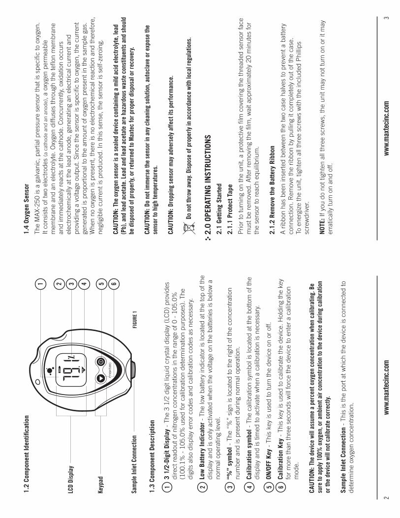
2ww
w.m
axte
cinc
.com
3ww
w.m
axte
cinc
.com
1.2
Com
pone
nt Id
entifi
catio
n
1.3
Com
pone
nt D
escr
iptio
n
1 3
1/2
-Dig
it Di
spla
y -
The
3 1/
2 di
git l
iqui
d cr
ysta
l dis
play
(LC
D)
prov
ides
di
rect
rea
dout
of n
itrog
en c
once
ntra
tions
in th
e ra
nge
of 0
- 1
05.0
%
(100
.1%
- 1
05.0
% u
sed
for
calib
ratio
n de
term
inat
ion
purp
oses
). T
he
digi
ts a
lso
disp
lay
erro
r co
des
and
calib
ratio
n co
des
as n
eces
sary
.
2 L
ow B
atte
ry In
dica
tor
- Th
e lo
w b
atte
ry in
dica
tor
is lo
cate
d at
the
top
of th
e di
spla
y an
d is
onl
y ac
tivat
ed w
hen
the
volta
ge o
n th
e ba
tterie
s is
bel
ow a
no
rmal
ope
ratin
g le
vel.
3 “
%”
sym
bol -
The
“%
” si
gn is
loca
ted
to th
e rig
ht o
f the
con
cent
ratio
n nu
mbe
r an
d is
pre
sent
dur
ing
norm
al o
pera
tion.
4 C
alib
ratio
n sy
mbo
l - T
he c
alib
ratio
n sy
mbo
l is
loca
ted
at th
e bo
ttom
of t
he
disp
lay
and
is ti
med
to a
ctiv
ate
whe
n a
calib
ratio
n is
nec
essa
ry.
5 O
N/O
FF K
ey -
Thi
s ke
y is
use
d to
turn
the
devi
ce o
n or
off.
6 C
alib
ratio
n Ke
y -
This
key
is u
sed
to c
alib
rate
the
devi
ce. H
oldi
ng th
e ke
y fo
r m
ore
than
thre
e se
cond
s w
ill fo
rce
the
devi
ce to
ent
er a
cal
ibra
tion
mod
e.
CAU
TION
: The
dev
ice
will
assu
me
a pe
rcen
t oxy
gen
conc
entr
atio
n wh
en c
alib
ratin
g. B
e su
re to
app
ly 1
00%
oxy
gen,
or a
mbi
ent a
ir co
ncen
trat
ion
to th
e de
vice
dur
ing
calib
ratio
n or
the
devi
ce w
ill n
ot c
alib
rate
cor
rect
ly.
Sam
ple
Inle
t Con
nect
ion
- Th
is is
the
port
at w
hich
the
devi
ce is
con
nect
ed to
de
term
ine
oxyg
en c
once
ntra
tion.
1.4
Oxyg
en S
enso
r
The
MA
X-25
0 is
a g
alva
nic,
par
tial p
ress
ure
sens
or th
at is
spe
cific
to o
xyge
n.
It co
nsis
ts o
f tw
o el
ectr
odes
(a c
atho
de a
nd a
n an
ode)
, a o
xyge
n pe
rmea
ble
mem
bran
e an
d an
ele
ctro
lyte
. Oxy
gen
diffu
ses
thro
ugh
the
teflo
n m
embr
ane
and
imm
edia
tely
rea
cts
at th
e ca
thod
e. C
oncu
rren
tly, o
xida
tion
occu
rs
elec
troc
hem
ical
ly a
t the
lead
ano
de, g
ener
atin
g an
ele
ctric
al c
urre
nt a
nd
prov
idin
g a
volta
ge o
utpu
t. Si
nce
the
sens
or is
spe
cific
to o
xyge
n, th
e cu
rren
t ge
nera
ted
is p
ropo
rtio
nal t
o th
e am
ount
of o
xyge
n pr
esen
t in
the
sam
ple
gas.
W
hen
no o
xyge
n is
pre
sent
, the
re is
no
elec
troc
hem
ical
rea
ctio
n an
d th
eref
ore,
ne
glig
ible
cur
rent
is p
rodu
ced.
In th
is s
ense
, the
sen
sor
is s
elf-
zero
ing.
CAU
TION
: The
oxy
gen
sens
or is
a s
eale
d de
vice
con
tain
ing
a m
ild a
cid
elec
trol
yte,
lead
(P
b), a
nd le
ad a
ceta
te. L
ead
and
lead
ace
tate
are
haz
ardo
us w
aste
con
stitu
ents
and
sho
uld
be d
ispo
sed
of p
rope
rly, o
r ret
urne
d to
Max
tec
for p
rope
r dis
posa
l or r
ecov
ery.
CAU
TION
: Do
not i
mm
erse
the
sens
or in
any
cle
anin
g so
lutio
n, a
utoc
lave
or e
xpos
e th
e se
nsor
to h
igh
tem
pera
ture
s.
CAU
TION
: Dro
ppin
g se
nsor
may
adv
erse
ly a
ffect
its
perf
orm
ance
.
Do
not t
hrow
awa
y. Di
spos
e of
pro
perly
in a
ccor
danc
e wi
th lo
cal r
egul
atio
ns.
2.0
OPE
RATI
NG
INST
RUCT
ION
S2.
1 Ge
tting
Sta
rted
2.1.
1 Pr
otec
t Tap
e
Prio
r to
turn
ing
on th
e un
it, a
pro
tect
ive
film
cov
erin
g th
e th
read
ed s
enso
r fa
ce
mus
t be
rem
oved
. Afte
r re
mov
ing
the
film
, wai
t app
roxi
mat
ely
20 m
inut
es fo
r th
e se
nsor
to r
each
equ
ilibr
ium
.
2.1.
2 Re
mov
e th
e Ba
ttery
Rib
bon
A r
ibbo
n ha
s be
en in
sert
ed b
etw
een
the
two
case
hal
ves
to p
reve
nt a
bat
tery
co
nnec
tion.
Rem
ove
the
ribbo
n by
pul
ling
it co
mpl
etel
y ou
t of t
he c
ase.
To
ene
rgiz
e th
e un
it, ti
ghte
n al
l thr
ee s
crew
s w
ith th
e in
clud
ed P
hilli
ps
scre
wdr
iver
.
NOT
E: If
you
do
not t
ight
en a
ll th
ree
scre
ws,
the
unit
may
not
turn
on
or it
may
er
ratic
ally
turn
on
and
off.
1
LCD
Disp
lay
2 3 4 5 6
FIGU
RE 1
Keyp
ad
Sam
ple
Inle
t Con
nect
ion
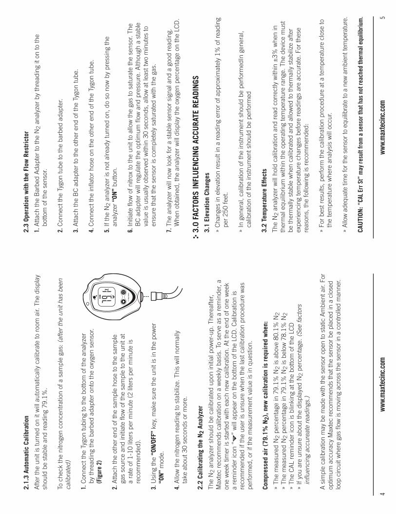
4ww
w.m
axte
cinc
.com
5ww
w.m
axte
cinc
.com
2.1.
3 Au
tom
atic
Cal
ibra
tion
Afte
r th
e un
it is
turn
ed o
n it
will
aut
omat
ical
ly c
alib
rate
to r
oom
air.
The
dis
play
sh
ould
be
stab
le a
nd r
eadi
ng 7
9.1%
.
To c
heck
the
nitr
ogen
con
cent
ratio
n of
a s
ampl
e ga
s: (
afte
r th
e un
it ha
s be
en
calib
rate
d)
1. C
onne
ct th
e Ty
gon
tubi
ng to
the
botto
m o
f the
ana
lyze
r by
thre
adin
g th
e ba
rbed
ada
pter
ont
o th
e ox
ygen
sen
sor.
(Fig
ure
2)
2. A
ttach
the
othe
r en
d of
the
sam
ple
hose
to th
e sa
mpl
e ga
s so
urce
and
initi
ate
flow
of t
he s
ampl
e to
the
unit
at
a ra
te o
f 1-1
0 lit
ers
per
min
ute
(2 li
ters
per
min
ute
is
reco
mm
ende
d).
3. U
sing
the
“ON
/OFF
” ke
y, m
ake
sure
the
unit
is in
the
pow
er
“ON
” m
ode.
4. A
llow
the
nitr
ogen
rea
ding
to s
tabi
lize.
Thi
s w
ill n
orm
ally
ta
ke a
bout
30
seco
nds
or m
ore.
2.2
Calib
ratin
g th
e N
2 An
alyz
er
The
N2
anal
yzer
sho
uld
be c
alib
rate
d up
on in
itial
pow
er-u
p. T
here
afte
r, M
axte
c re
com
men
ds c
alib
ratio
n on
a w
eekl
y ba
sis.
To
serv
e as
a r
emin
der,
a on
e w
eek
timer
is s
tart
ed w
ith e
ach
new
cal
ibra
tion.
At t
he e
nd o
f one
wee
k a
rem
inde
r ic
on “
” w
ill a
ppea
r on
the
botto
m o
f the
LC
D. C
alib
ratio
n is
re
com
men
ded
if th
e us
er is
uns
ure
whe
n th
e la
st c
alib
ratio
n pr
oced
ure
was
pe
rfor
med
, or
if th
e m
easu
rem
ent v
alue
is in
que
stio
n.
Com
pres
sed
air
(79.
1% N
2), n
ew c
alib
ratio
n is
req
uire
d w
hen:
» Th
e m
easu
red
N2
perc
enta
ge in
79.
1% N
2 is
abo
ve 8
0.1%
N2
» Th
e m
easu
red
N2
perc
enta
ge in
79.
1% N
2 is
bel
ow 7
8.1%
N2
» Th
e C
AL
rem
inde
r ic
on is
blin
king
at t
he b
otto
m o
f the
LC
D»
If yo
u ar
e un
sure
abo
ut th
e di
spla
yed
N2
perc
enta
ge. (
See
fact
ors
influ
enci
ng a
ccur
eate
rea
ding
s.)
A s
impl
e ca
libra
tion
may
be
mad
e w
ith th
e se
nsor
ope
n to
sta
tic A
mbi
ent a
ir. F
or
optim
um a
ccur
acy
Max
tec
reco
mm
ends
that
the
sens
or b
e pl
aced
in a
clo
sed
loop
circ
uit w
here
gas
flow
is m
ovin
g ac
ross
the
sens
or in
a c
ontr
olle
d m
anne
r.
2.3
Oper
atio
n w
ith th
e Fl
ow R
estr
icto
r
1. A
ttach
the
Bar
bed
Ada
pter
to th
e N
2 an
alyz
er b
y th
read
ing
it on
to th
e bo
ttom
of t
he s
enso
r.
2. C
onne
ct th
e Ty
gon
tube
to th
e ba
rbed
ada
pter
.
3. A
ttach
the
BC
ada
pter
to th
e ot
her
end
of th
e Ty
gon
tube
.
4. C
onne
ct th
e in
flato
r ho
se o
n th
e ot
her
end
of th
e Ty
gon
tube
.
5. If
the
N2
anal
yzer
is n
ot a
lread
y tu
rned
on,
do
so n
ow b
y pr
essi
ng th
e an
alyz
er “
ON”
butto
n.
6. In
itiat
e flo
w o
f nitr
ox to
the
unit
to a
llow
the
gas
to s
atur
ate
the
sens
or. T
he
BC
ada
pter
will
reg
ulat
e th
e op
timum
flow
and
pre
ssur
e. A
lthou
gh a
sta
ble
valu
e is
usu
ally
obs
erve
d w
ithin
30
seco
nds,
allo
w a
t lea
st tw
o m
inut
es to
en
sure
that
the
sens
or is
com
plet
ely
satu
rate
d w
ith th
e ga
s.
7. T
he a
naly
zer
will
now
look
for
a st
able
sen
sor
sign
al a
nd a
goo
d re
adin
g.
Whe
n ob
tain
ed, t
he a
naly
zer
will
dis
play
the
oxyg
en p
erce
ntag
e on
the
LCD
.
3.0
FAC
TORS
INFL
UEN
CIN
G AC
CURA
TE R
EADI
NGS
3.1
Elev
atio
n Ch
ange
s
» C
hang
es in
ele
vatio
n re
sult
in a
rea
ding
err
or o
f app
roxi
mat
ely
1% o
f rea
ding
pe
r 25
0 fe
et.
» In
gen
eral
, cal
ibra
tion
of th
e in
stru
men
t sho
uld
be p
erfo
rmed
In g
ener
al,
calib
ratio
n of
the
inst
rum
ent s
houl
d be
per
form
ed
3.2
Tem
pera
ture
Effe
cts
The
N2
anal
yzer
will
hol
d ca
libra
tion
and
read
cor
rect
ly w
ithin
±3%
whe
n in
th
erm
al e
quili
briu
m w
ithin
the
oper
atin
g te
mpe
ratu
re r
ange
. The
dev
ice
mus
t be
ther
mal
ly s
tabl
e w
hen
calib
rate
d an
d al
low
ed to
ther
mal
ly s
tabi
lize
afte
r ex
perie
ncin
g te
mpe
ratu
re c
hang
es b
efor
e re
adin
gs a
re a
ccur
ate.
For
thes
e re
ason
s, th
e fo
llow
ing
is r
ecom
men
ded:
» Fo
r be
st r
esul
ts, p
erfo
rm th
e ca
libra
tion
proc
edur
e at
a te
mpe
ratu
re c
lose
to
the
tem
pera
ture
whe
re a
naly
sis
will
occ
ur.
» A
llow
ade
quat
e tim
e fo
r th
e se
nsor
to e
quili
brat
e to
a n
ew a
mbi
ent t
empe
ratu
re.
CAU
TION
: “CA
L Er
r St”
may
resu
lt fr
om a
sen
sor t
hat h
as n
ot re
ache
d th
erm
al e
quili
briu
m.
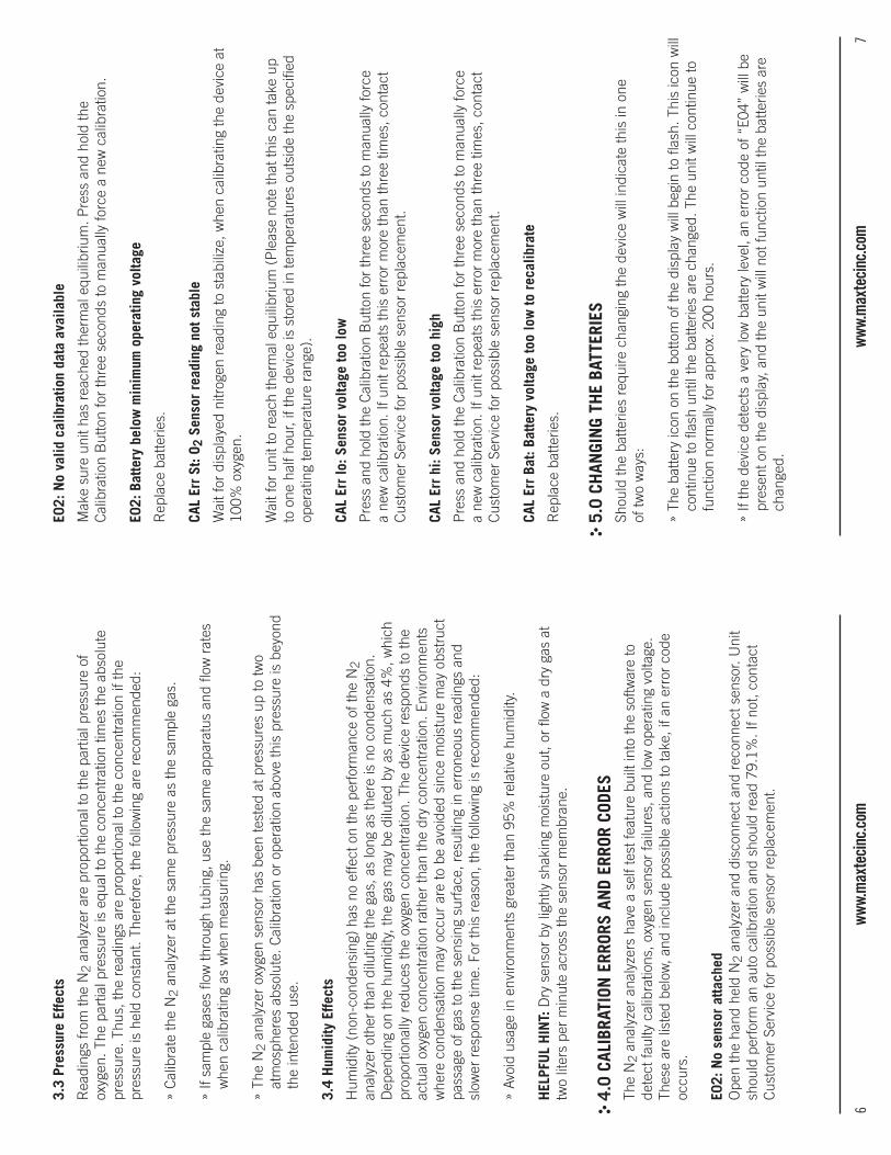
6ww
w.m
axte
cinc
.com
7ww
w.m
axte
cinc
.com
3.3
Pres
sure
Effe
cts
Rea
ding
s fr
om th
e N
2 an
alyz
er a
re p
ropo
rtio
nal t
o th
e pa
rtia
l pre
ssur
e of
ox
ygen
. The
par
tial p
ress
ure
is e
qual
to th
e co
ncen
trat
ion
times
the
abso
lute
pr
essu
re. T
hus,
the
read
ings
are
pro
port
iona
l to
the
conc
entr
atio
n if
the
pres
sure
is h
eld
cons
tant
. The
refo
re, t
he fo
llow
ing
are
reco
mm
ende
d:
» C
alib
rate
the
N2
anal
yzer
at t
he s
ame
pres
sure
as
the
sam
ple
gas.
» If
sam
ple
gase
s flo
w th
roug
h tu
bing
, use
the
sam
e ap
para
tus
and
flow
rat
es
whe
n ca
libra
ting
as w
hen
mea
surin
g.
» Th
e N
2 an
alyz
er o
xyge
n se
nsor
has
bee
n te
sted
at p
ress
ures
up
to tw
o at
mos
pher
es a
bsol
ute.
Cal
ibra
tion
or o
pera
tion
abov
e th
is p
ress
ure
is b
eyon
d th
e in
tend
ed u
se.
3.4
Hum
idity
Effe
cts
Hum
idity
(no
n-co
nden
sing
) ha
s no
effe
ct o
n th
e pe
rfor
man
ce o
f the
N2
anal
yzer
oth
er th
an d
ilutin
g th
e ga
s, a
s lo
ng a
s th
ere
is n
o co
nden
satio
n.
Dep
endi
ng o
n th
e hu
mid
ity, t
he g
as m
ay b
e di
lute
d by
as
muc
h as
4%
, whi
ch
prop
ortio
nally
red
uces
the
oxyg
en c
once
ntra
tion.
The
dev
ice
resp
onds
to th
e ac
tual
oxy
gen
conc
entr
atio
n ra
ther
than
the
dry
conc
entr
atio
n. E
nviro
nmen
ts
whe
re c
onde
nsat
ion
may
occ
ur a
re to
be
avoi
ded
sinc
e m
oist
ure
may
obs
truc
t pa
ssag
e of
gas
to th
e se
nsin
g su
rfac
e, r
esul
ting
in e
rron
eous
rea
ding
s an
d sl
ower
res
pons
e tim
e. F
or th
is r
easo
n, th
e fo
llow
ing
is r
ecom
men
ded:
» Av
oid
usag
e in
env
ironm
ents
gre
ater
than
95%
rel
ativ
e hu
mid
ity.
HEL
PFU
L H
INT:
Dry
sen
sor
by li
ghtly
sha
king
moi
stur
e ou
t, or
flow
a d
ry g
as a
t tw
o lit
ers
per
min
ute
acro
ss th
e se
nsor
mem
bran
e.
4.0
CAL
IBRA
TION
ERR
ORS
AND
ERRO
R CO
DES
The
N2
anal
yzer
ana
lyze
rs h
ave
a se
lf te
st fe
atur
e bu
ilt in
to th
e so
ftwar
e to
de
tect
faul
ty c
alib
ratio
ns, o
xyge
n se
nsor
failu
res,
and
low
ope
ratin
g vo
ltage
. Th
ese
are
liste
d be
low
, and
incl
ude
poss
ible
act
ions
to ta
ke, i
f an
erro
r co
de
occu
rs.
E02:
No
sens
or a
ttach
edO
pen
the
hand
hel
d N
2 an
alyz
er a
nd d
isco
nnec
t and
rec
onne
ct s
enso
r. U
nit
shou
ld p
erfo
rm a
n au
to c
alib
ratio
n an
d sh
ould
rea
d 79
.1%
. If n
ot, c
onta
ct
Cus
tom
er S
ervi
ce fo
r po
ssib
le s
enso
r re
plac
emen
t.
E02:
No
valid
cal
ibra
tion
data
ava
ilabl
e
Mak
e su
re u
nit h
as r
each
ed th
erm
al e
quili
briu
m. P
ress
and
hol
d th
e C
alib
ratio
n B
utto
n fo
r th
ree
seco
nds
to m
anua
lly fo
rce
a ne
w c
alib
ratio
n.
E02:
Bat
tery
bel
ow m
inim
um o
pera
ting
volta
ge
Rep
lace
bat
terie
s.
CAL
Err
St: O
2 Se
nsor
rea
ding
not
sta
ble
Wai
t for
dis
play
ed n
itrog
en r
eadi
ng to
sta
biliz
e, w
hen
calib
ratin
g th
e de
vice
at
100%
oxy
gen.
Wai
t for
uni
t to
reac
h th
erm
al e
quili
briu
m (
Ple
ase
note
that
this
can
take
up
to o
ne h
alf h
our,
if th
e de
vice
is s
tore
d in
tem
pera
ture
s ou
tsid
e th
e sp
ecifi
ed
oper
atin
g te
mpe
ratu
re r
ange
).
CAL
Err
lo: S
enso
r vo
ltage
too
low
Pre
ss a
nd h
old
the
Cal
ibra
tion
But
ton
for
thre
e se
cond
s to
man
ually
forc
e a
new
cal
ibra
tion.
If u
nit r
epea
ts th
is e
rror
mor
e th
an th
ree
times
, con
tact
C
usto
mer
Ser
vice
for
poss
ible
sen
sor
repl
acem
ent.
CAL
Err
hi: S
enso
r vo
ltage
too
high
Pre
ss a
nd h
old
the
Cal
ibra
tion
But
ton
for
thre
e se
cond
s to
man
ually
forc
e a
new
cal
ibra
tion.
If u
nit r
epea
ts th
is e
rror
mor
e th
an th
ree
times
, con
tact
C
usto
mer
Ser
vice
for
poss
ible
sen
sor
repl
acem
ent.
CAL
Err
Bat:
Batte
ry v
olta
ge to
o lo
w to
rec
alib
rate
Rep
lace
bat
terie
s.
5.0
CH
ANGI
NG
THE
BATT
ERIE
SSh
ould
the
batte
ries
requ
ire c
hang
ing
the
devi
ce w
ill in
dica
te th
is in
one
of
two
way
s:
» Th
e ba
ttery
icon
on
the
botto
m o
f the
dis
play
will
beg
in to
flas
h. T
his
icon
will
co
ntin
ue to
flas
h un
til th
e ba
tterie
s ar
e ch
ange
d. T
he u
nit w
ill c
ontin
ue to
fu
nctio
n no
rmal
ly fo
r ap
prox
. 200
hou
rs.
» If
the
devi
ce d
etec
ts a
ver
y lo
w b
atte
ry le
vel,
an e
rror
cod
e of
“E0
4” w
ill b
e pr
esen
t on
the
disp
lay,
and
the
unit
will
not
func
tion
until
the
batte
ries
are
chan
ged.
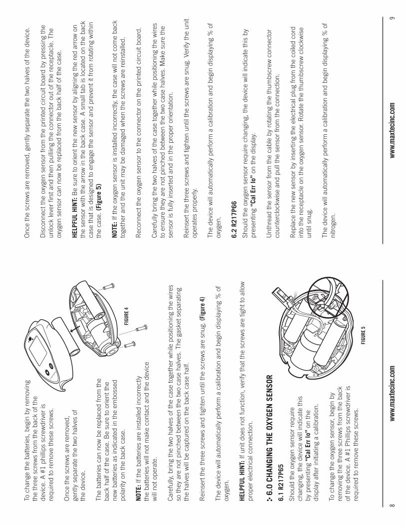
8ww
w.m
axte
cinc
.com
9ww
w.m
axte
cinc
.com
To c
hang
e th
e ba
tterie
s, b
egin
by
rem
ovin
g
the
thre
e sc
rew
s fr
om th
e ba
ck o
f the
de
vice
. A #
1 ph
illip
s sc
rew
driv
er is
re
quire
d to
rem
ove
thes
e sc
rew
s.
Onc
e th
e sc
rew
s ar
e re
mov
ed,
gent
ly s
epar
ate
the
two
halv
es o
f th
e de
vice
.
The
batte
ries
can
now
be
repl
aced
from
the
ba
ck h
alf o
f the
cas
e. B
e su
re to
orie
nt th
e
new
bat
terie
s as
indi
cate
d in
the
embo
ssed
po
larit
y on
the
back
cas
e.
NOT
E: If
the
batte
ries
are
inst
alle
d in
corr
ectly
th
e ba
tterie
s w
ill n
ot m
ake
cont
act a
nd th
e de
vice
w
ill n
ot o
pera
te.
Car
eful
ly, b
ring
the
two
halv
es o
f the
cas
e to
geth
er w
hile
pos
ition
ing
the
wire
s so
they
are
not
pin
ched
bet
wee
n th
e tw
o ca
se h
alve
s. T
he g
aske
t sep
arat
ing
th
e ha
lves
will
be
capt
ured
on
the
back
cas
e ha
lf.
Rei
nser
t the
thre
e sc
rew
s an
d tig
hten
unt
il th
e sc
rew
s ar
e sn
ug. (
Figu
re 4
)
The
devi
ce w
ill a
utom
atic
ally
per
form
a c
alib
ratio
n an
d be
gin
disp
layi
ng %
of
oxyg
en.
HEL
PFU
L H
INT:
If u
nit d
oes
not f
unct
ion,
ver
ify th
at th
e sc
rew
s ar
e tig
ht to
allo
w
prop
er e
lect
rical
con
nect
ion.
6.0
CH
ANGI
NG
THE
OXYG
EN S
ENSO
R6.
1 R2
17P6
5
Shou
ld th
e ox
ygen
sen
sor
requ
ire
chan
ging
, the
dev
ice
will
indi
cate
this
by
pre
sent
ing
“Cal
Err
lo”
on th
e
disp
lay
afte
r in
itiat
ing
a ca
libra
tion.
To c
hang
e th
e ox
ygen
sen
sor,
begi
n by
re
mov
ing
the
thre
e sc
rew
s fr
om th
e ba
ck
of th
e de
vice
. A #
1 P
hilli
ps s
crew
driv
er is
re
quire
d to
rem
ove
thes
e sc
rew
s.
Onc
e th
e sc
rew
s ar
e re
mov
ed, g
ently
sep
arat
e th
e tw
o ha
lves
of t
he d
evic
e.
Dis
conn
ect t
he o
xyge
n se
nsor
from
the
prin
ted
circ
uit b
oard
by
pres
sing
the
unlo
ck le
ver
first
and
then
pul
liing
the
conn
ecto
r ou
t of t
he r
ecep
tacl
e. T
he
oxyg
en s
enso
r ca
n no
w b
e re
plac
ed fr
om th
e ba
ck h
alf o
f the
cas
e.
HEL
PFU
L H
INT:
Be
sure
to o
rient
the
new
sen
sor
by a
ligni
ng th
e re
d ar
row
on
the
sens
or w
ith th
e ar
row
in th
e ba
ck c
ase.
A s
mal
l tab
is lo
cate
d on
the
back
ca
se th
at is
des
igne
d to
eng
age
the
sens
or a
nd p
reve
nt it
from
rot
atin
g w
ithin
th
e ca
se. (
Figu
re 5
)
NOT
E: If
the
oxyg
en s
enso
r is
inst
alle
d in
corr
ectly
, the
cas
e w
ill n
ot c
ome
back
to
geth
er a
nd th
e un
it m
ay b
e da
mag
ed w
hen
the
scre
ws
are
rein
stal
led.
Rec
onne
ct th
e ox
ygen
sen
sor
to th
e co
nnec
tor
on th
e pr
inte
d ci
rcui
t boa
rd.
Car
eful
ly b
ring
the
two
halv
es o
f the
cas
e to
geth
er w
hile
pos
ition
ing
the
wire
s to
ens
ure
they
are
not
pin
ched
bet
wee
n th
e tw
o ca
se h
alve
s. M
ake
sure
the
sens
or is
fully
inse
rted
and
in th
e pr
oper
orie
ntat
ion.
Rei
nser
t the
thre
e sc
rew
s an
d tig
hten
unt
il th
e sc
rew
s ar
e sn
ug. V
erify
the
unit
oper
ates
pro
perly
.
The
devi
ce w
ill a
utom
atic
ally
per
form
a c
alib
ratio
n an
d be
gin
disp
layi
ng %
of
oxyg
en.
6.2
R217
P66
Shou
ld th
e ox
ygen
sen
sor
requ
ire c
hang
ing,
the
devi
ce w
ill in
dica
te th
is b
y pr
esen
ting
“Cal
Err
lo”
on th
e di
spla
y.
Unt
hrea
d th
e se
nsor
from
the
cabl
e by
rot
atin
g th
e th
umbs
crew
con
nect
or
coun
terc
lock
wis
e an
d pu
ll th
e se
nsor
from
the
conn
ectio
n.
Rep
lace
the
new
sen
sor
by in
sert
ing
the
elec
tric
al p
lug
from
the
coile
d co
rd
into
the
rece
ptac
le o
n th
e ox
ygen
sen
sor.
Rot
ate
the
thum
bscr
ew c
lock
wis
e un
til s
nug.
The
devi
ce w
ill a
utom
atic
ally
per
form
a c
alib
ratio
n an
d be
gin
disp
layi
ng %
of
nitr
ogen
.
FIGU
RE 4
FIGU
RE 5
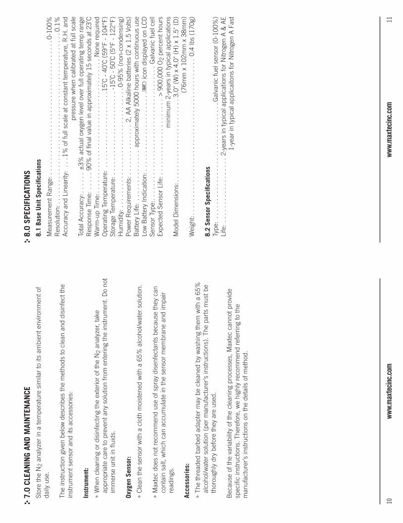
10ww
w.m
axte
cinc
.com
11ww
w.m
axte
cinc
.com
7.0
CLE
ANIN
G AN
D M
AIN
TEN
ANCE
Stor
e th
e N
2 an
alyz
er in
a te
mpe
ratu
re s
imila
r to
its
ambi
ent e
nviro
nmen
t of
daily
use
.
The
inst
ruct
ion
give
n be
low
des
crib
es th
e m
etho
ds to
cle
an a
nd d
isin
fect
the
inst
rum
ent s
enso
r an
d its
acc
esso
ries:
Inst
rum
ent:
» W
hen
clea
ning
or
disi
nfec
ting
the
exte
rior
of th
e N
2 an
alyz
er, t
ake
appr
opria
te c
are
to p
reve
nt a
ny s
olut
ion
from
ent
erin
g th
e in
stru
men
t. D
o no
t im
mer
se u
nit i
n flu
ids.
Oxyg
en S
enso
r:
» C
lean
the
sens
or w
ith a
clo
th m
oist
ened
with
a 6
5% a
lcoh
ol/w
ater
sol
utio
n.
» M
axte
c do
es n
ot r
ecom
men
d us
e of
spr
ay d
isen
fect
ants
bec
ause
they
can
co
ntai
n sa
lt, w
hich
can
acc
umul
ate
in th
e se
nsor
mem
bran
e an
d im
pair
read
ings
.
Acce
ssor
ies:
» Th
e th
read
ed b
arbe
d ad
apte
r m
ay b
e cl
eane
d by
was
hing
them
with
a 6
5%
alco
hol/w
ater
sol
utio
n (p
er m
anuf
actu
rer’s
inst
ruct
ions
). T
he p
arts
mus
t be
thor
ough
ly d
ry b
efor
e th
ey a
re u
sed.
Bec
ause
of t
he v
aria
bilit
y of
the
clea
ning
pro
cess
es, M
axte
c ca
nnot
pro
vide
sp
ecifi
c in
stru
ctio
ns. T
here
fore
, we
high
ly r
ecom
men
d re
ferr
ing
to th
e m
anuf
actu
rer’s
inst
ruct
ions
on
the
deta
ils o
f met
hod.
8.0
SPE
CIFI
CATI
ONS
8.1
Base
Uni
t Spe
cific
atio
ns
Mea
sure
men
t Ran
ge: .
. . .
. . .
. . .
. . .
. . .
. . .
. . .
. . .
. . .
. . .
. . .
. . .
0-10
0%R
esol
utio
n:..
....
....
....
....
....
....
....
....
....
....
....
.0.1
%A
ccur
acy
and
Line
arity
: . .
.1%
of f
ull s
cale
at c
onst
ant t
empe
ratu
re, R
.H. a
nd
pres
sure
whe
n ca
libra
ted
at fu
ll sc
ale
Tota
l Acc
urac
y:..
....
±3%
act
ual o
xyge
n le
vel o
ver
full
oper
atin
g te
mp
rang
eR
espo
nse
Tim
e: .
....
90%
of fi
nal v
alue
in a
ppro
xim
atel
y 15
sec
onds
at 2
3˚C
War
m-u
p Ti
me:
....
....
....
....
....
....
....
....
....
.Non
e re
quire
dO
pera
ting
Tem
pera
ture
: ..
....
....
....
....
...1
5˚C
- 4
0˚C
(59
°F -
104
°F)
Stor
age
Tem
pera
ture
: ..
....
....
....
....
....
.-1
5˚C
- 5
0˚C
(5°
F -
122°
F)H
umid
ity: .
. . .
. . .
. . .
. . .
. . .
. . .
. . .
. . .
. . .
. . .
. .0
-95%
(no
n-co
nden
sing
) P
ower
Req
uire
men
ts: .
. . .
. . .
. . .
. . .
. 2,
AA
Alk
alin
e ba
tterie
s (2
x 1
.5 V
olts
)B
atte
ry L
ife:
....
....
....
..ap
prox
imat
ely
5000
hou
rs w
ith c
ontin
uous
use
Low
Bat
tery
Indi
catio
n: .
. . .
. . .
. . .
. . .
. . .
. . .
. . .
BAT
icon
dis
play
ed o
n LC
DSe
nsor
Typ
e:..
....
....
....
....
....
....
....
....
...
Gal
vani
c fu
el c
ell
Expe
cted
Sen
sor
Life
: . .
. . .
. . .
. . .
. . .
. . .
. . .
. >
900
,000
O2
perc
ent h
ours
m
inim
um 2
-yea
rs in
typi
cal a
pplic
atio
nsM
odel
Dim
ensi
ons:
....
....
....
....
....
...3
.0"
(W)
x 4.
0" (
H)
x 1.
5" (
D)
(7
6mm
x 1
02m
m x
38m
m)
Wei
ght:
....
....
....
....
....
....
....
....
....
....
...
0.4
lbs
(170
g)
8.2
Sens
or S
peci
ficat
ions
Type
: ..
....
....
....
....
....
....
....
..G
alva
nic
fuel
sen
sor
(0-1
00%
)Li
fe:
....
....
....
....
..2-
year
s in
typi
cal a
pplic
atio
ns fo
r N
itrog
en A
& A
E
1-ye
ar in
typi
cal a
pplic
aito
ns fo
r N
itrog
en A
Fas
t
12ww
w.m
axte
cinc
.com
13ww
w.m
axte
cinc
.com
9.0
WAR
RAN
TYTh
e N
2 an
alyz
er is
des
igne
d fo
r ni
trog
en d
eliv
ery
equi
pmen
t and
sys
tem
s.
Und
er n
orm
al o
pera
ting
cond
ition
s, M
axte
c w
arra
nts
the
N2
anal
yzer
to
be fr
ee fr
om d
efec
ts o
f wor
kman
ship
or
mat
eria
ls fo
r a
perio
d of
2-y
ears
fr
om th
e da
te o
f shi
pmen
t fro
m M
axte
c, p
rovi
ded
that
the
unit
is p
rope
rly
oper
ated
and
mai
ntai
ned
in a
ccor
danc
e w
ith M
axte
c’s
oper
atin
g in
stru
ctio
ns.
Bas
ed o
n M
axte
c’s
prod
uct e
valu
atio
n, M
axte
c's
sole
obl
igat
ion
unde
r th
e fo
rego
ing
war
rant
y is
lim
ited
to m
akin
g re
plac
emen
ts, r
epai
rs, o
r is
suin
g cr
edit
for
equi
pmen
t fou
nd to
be
defe
ctiv
e. T
his
war
rant
y ex
tend
s on
ly to
the
buye
r pu
rcha
sing
the
equi
pmen
t dire
ctly
. Max
tec'
s so
le o
blig
atio
n un
der
the
fore
goin
g w
arra
nty
is li
mite
d to
mak
ing
repl
acem
ents
, rep
airs
, or
issu
ing
cred
it fo
r eq
uipm
ent f
ound
to b
e de
fect
ive.
Thi
s w
arra
nty
exte
nds
only
to th
e bu
yer
purc
hasi
ng th
e eq
uipm
ent d
irect
ly fr
om M
axte
c th
roug
h M
axte
c's
desi
gned
di
strib
utor
s an
d ag
ents
as
new
equ
ipm
ent.
Max
tec
war
rant
s th
e ox
ygen
sen
sor
in th
e N
2 an
alyz
er to
be
free
from
def
ects
in
mat
eria
l and
wor
kman
ship
for
a pe
riod
of 2
-yea
rs fo
r N
itrog
en A
& A
E an
d 1-
year
for
Nitr
ogen
A F
ast f
rom
Max
tec'
s da
te o
f shi
pmen
t in
a N
2 an
alyz
er.
Shou
ld a
sen
sor
fail
prem
atur
ely,
the
repl
acem
ent s
enso
r is
war
rant
ed fo
r th
e re
mai
nder
of t
he o
rigin
al s
enso
r w
arra
nty
perio
d.
Rou
tine
mai
nten
ance
item
s, s
uch
as b
atte
ries,
are
exc
lude
d fr
om w
arra
nty.
M
axte
c an
d an
y ot
her
subs
idia
ries
shal
l not
be
liabl
e to
the
purc
hase
r or
oth
er
pers
ons
for
inci
dent
al o
r co
nseq
uent
ial d
amag
es o
r eq
uipm
ent t
hat h
as b
een
subj
ect t
o ab
use,
mis
use,
mis
-app
licat
ion,
alte
ratio
n, n
eglig
ence
or
acci
dent
.
Thes
e w
arra
ntie
s ar
e ex
clus
ive
and
in li
eu o
f all
othe
r w
arra
ntie
s, e
xpre
ssed
or
impl
ied,
incl
udin
g w
arra
nty
of m
erch
anta
bilit
y an
d fit
ness
for
a pa
rtic
ular
pu
rpos
e.
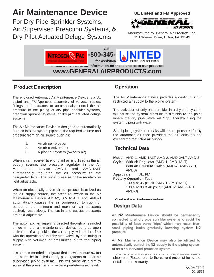
Air Maintenance DeviceFor Dry Pipe Sprinkler Systems,Air Supervised Preaction Systems, &Dry Pilot Actuated Deluge Systems
UL Listed and FM Approved
Manufactured by: General Air Products, Inc.118 Summit Drive, Exton, PA 19341
Product Description
The enclosed Automatic Air Maintenance Device is a ULListed and FM Approved assembly of valves, nipples,fittings, and actuators to automatically control the airpressure in the piping of dry pipe sprinkler systems,preaction sprinkler systems, or dry pilot actuated delugesystems.
The Air Maintenance Device is designed to automaticallyfeed air into the system piping at the required volume andpressure from an air source such as:
1. An air compressor2. An air receiver tank3. A plant air system (owner's air)
When an air receiver tank or plant air is utilized as the airsupply source, the pressure regulator in the AirMaintenance Device AMD-1 and AMD-1ALTautomatically regulates the air pressure to thedesignated level. The outlet pressure of the regulator isfield adjustable.
When an electrically-driven air compressor is utilized asthe air supply source, the pressure switch in the AirMaintenance Device AMD-2, AMD-2ALT and AMD-3automatically causes the air compressor to cut-in orcut-out at the minimum and maximum air pressuresdesired, respectively. The cut-in and cut-out pressuresare field adjustable.
The automatic air supply is directed through a restrictedorifice in the air maintenance device so that uponactivation of a sprinkler, the air supply will not interferewith the operation of the dry pipe valve, by continuing tosupply high volumes of pressurized air to the pipingsystem.
It is a recommended safeguard that a low pressure switchand alarm be installed on dry pipe systems or other airsupervised piping systems. This will cause an alarm tosound if the pressure falls below a predetermined level.
Operation
The Air Maintenance Device provides a continuous butrestricted air supply to the piping system.
The activation of only one sprinkler in a dry pipe system,will cause the system pressure to diminish to the pointwhere the dry pipe valve will “trip”, thereby filling thesystem piping with water.
Small piping system air leaks will be compensated for bythe automatic air feed provided the air leaks do notexceed the restricted air supply.
Technical Data
Model: AMD-1, AMD-1ALT; AMD-2, AMD-2ALT; AMD-3Style: With Air Regulator (AMD-1, AMD-1ALT)
With Air Pressure Switch (AMD-2, AMD-2ALT, AMD3)
Approvals: UL, FMFactory Operation Test:
100% at 35 psi air (AMD-1, AMD-1ALT)100% at 30 & 40 psi air (AMD-2, AMD-2ALT, AMD-3)
Ordering Information
Mfgr. Source: General Air Products, Inc.Weight: 7 lbs. (AMD-1, AMD-1ALT)
11 lbs. (AMD-2, AMD-2ALT, AMD-3)When placing an order, indicate the full product name.Please specify the quantity, model and style.
Guarantee
General Air Products, Inc. will repair and/or replace anyproducts found to be defective in material orworkmanship within a period of one year from the date ofshipment. Please refer to the current price list for furtherdetails of the warranty.
Call
1-800-345-8207for assistance
or visit our website for information on these and all of our products
www.GENERALAIRPRODUCTS.com
AMDMSTR.301/16/13
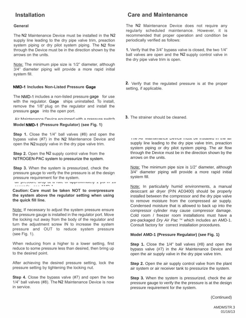
Design Data
An Air Maintenance Device should be permanentlyconnected to all dry pipe sprinkler systems to avoid thepossibility of false valve “trips” which may result fromsmall piping leaks gradually lowering system airpressure.
An Air Maintenance Device may also be utilized toautomatically control the air supply to the piping systemof an air supervised preaction system or to the pilot linesof a dry pilot actuated deluge valve.
There are several methods of providing a constant andcontrolled supply of air to a sprinkler system as follows:
Air Compressor and Air Maintenance Device Model(AMD-2)
The air compressor is connected electrically andmechanically to the trim of the dry pipe valve, through anAir Maintenance Device equipped with a pressure switch.The air pressure switch continuously senses the airpressure in the piping system and turns the compressoron if the pressure drops below the cut-in setting and turnsthe compressor off if the pressure rises above the cut-outsetting. The cut-in pressure is usually set at the designair pressure for maintaining the dry pipe valve in theclosed position. The cut-out pressure should be setapproximately 10 psi above the cut-in pressure.
Note: If the dry pipe valve is equipped with anaccelerator, this method of air maintenance is notrecommended. The accelerator is sensitive to a 3 to 5 psiair pressure drop at a rate of approximately 1 psi in 10seconds - see AMD-1.
Air Compressor with Air Receiver Tank and AirMaintenance Device (Model AMD-1)
The compressor-tank unit is equipped with an integralpressure switch that controls the pressure in the tank,maintaining the tank pressure at a level 10 to 15 psiabove the designed air pressure demand of any dry pipesystem supplied by the air compressor tank unit. Thecompressor-tank unit is mechanically connected to thetrim of the dry pipe valve, through an Air MaintenanceDevice equipped with an air pressure regulator. Thepressure regulator continuously regulates the incomingair (from the air receiver tank) and maintains the outgoingair pressure at the pressure setting of the regulator,usually within an accuracy of 1 psi. The outgoing airpressure setting is field adjustable from 5 to 75 psi. If thedry pipe valve is equipped with an accelerator, thismethod of air-maintenance is recommended.
AMD-1 Includes Non-Listed Pressure Gauge
The AMD-1 includes a non-listed pressure guage for usewith the regulator. Gauge ships uninstalled. To install,remove the 1/8” plug on the regulator and install thepressure gauge into the open port.
Plant Air Supply and Air Maintenance Device (AMD-1)
The plant air supply is mechanically connected to the trimof the dry pipe valve through an Air Maintenance Deviceequipped with an air pressure regulator. The pressureregulator continuously regulates the incoming air andmaintains the outgoing air pressure at the pressuresetting of the regulator, usually within and accuracy of 1psi. The outgoing air pressure setting is field adjustablefrom 5 to 75 psi. The minimum pressure in the plant airsupply must be greater than the design air pressurerequired by the dry pipe system since the air pressureregulator will only regulate pressure downward.
Installation
General
The Air Maintenance Device must be installed in the airsupply line leading to the dry pipe valve trim, preactionsystem piping or dry pilot system piping. The air flowthrough the Device must be in the direction shown by thearrows on the units.
Note: The minimum pipe size is 1/2” diameter, although3/4” diameter piping will provide a more rapid initialsystem fill.
Note: In particularly humid environments, a manualdesiccant air dryer (P/N AD3400) should be properlyinstalled between the compressor and the dry pipe valveto remove moisture from the compressed air supply.Condensed moisture that is allowed to back up into thecompressor cylinder may cause compressor damage.Cold room / freezer room installations must have apre-packaged Dry Air Pac TM which includes an AMD-1.Consult factory for correct installation procedures.
Model AMD-1 (Pressure Regulator) (see Fig. 1)
Step 1. Close the 1/4” ball valves (#8) and open thebypass valve (#7) in the Air Maintenance Device andopen the air supply valve in the dry pipe valve trim.
Step 2. Open the air supply control valve from the plantair system or air receiver tank to pressurize the system.
Step 3. When the system is pressurized, check the airpressure gauge to verify the the pressure is at the designpressure requirement for the system.
(Continued)
AMDMSTR.301/16/13
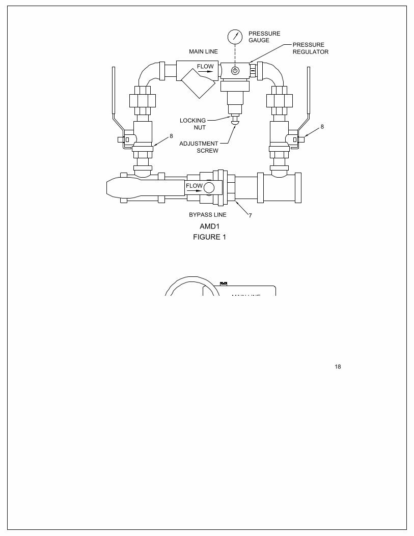
AMD1
FLOW
FLOW
MAIN LINE
BYPASS LINE
88
7
18
MAIN LINE
AMD2
BYPASS LINE
FLOW
18
FLOW
17
PRESSUREGAUGE
PRESSUREREGULATOR
LOCKINGNUT
ADJUSTMENTSCREW
FIGURE 1
FIGURE 2


MODEL SSS-100
DESIGN, INSTALLATION, OPERATION, AND MAINTENANCE MANUAL
Serial Number _______________________________________________ Date of Installation ____________Date of Commissioning ___________
UNITED Fire Systems Division of UNITED Fire Protection Corporation
1 Mark Road Kenilworth, NJ USA 07033 Manual Part Number 10-540001-001 908-688-0300 Revision 2.00 www.unitedfiresystems.net January 2015