Embed Size (px)
Citation preview

0 to 60: A Milestone Update in the Development of a Holistic Corrosion Prevention & Control Program NICHOLAS D’ANGELO, E.I.
ASSOCIATE CORROSION ENGINEER

Introduction
• B.S. in Corrosion Engineering, 2018
• NACE Certified CP Level II (#71600)
• Corrosion Prevention & Control Program Engineer• Responsible for revamping CWD’s cathodic
protection approach

Overview
Program Updates
ECCR Project
Design Manual DevelopmentDocument OverviewDesign GuidelinesDecision Matrix
Continuing Work

Program Updates
• Program Management
• Specification Development
• Common Design Guidelines
• Standard Operating Procedures
• Water Main Design Review
• Failure Analysis (FA)
• Corrosion Education
• Utility Coordination
Corrosion Prevention & Control (CPC)
July 2018
2019
2020
2021
Baseline Assessments
Program Development
Program Implementation
Program Implementation Cont.
Inventory & Pre-Assessments 2018 ICCP BASELINE ASSESSMENT REPORT
Record Drawings Digitization Project GIS Integration, Equipment Procurement, Soil Sampling, ICCP Tank Rehabilitation NACE IMPACT Plus Assessment
Unmanned Aerial System (UAS) Facility InspectionsExternal Corrosion Control Design Manual Draft SOP Development & RefinementFailure Analysis
External Corrosion Control Design Manual Finalization ECCR Construction + RMU UpgradeContinued Equipment ProcurementExpanding CP Consultant Pool

Asset Overview Cleveland Water has an extensive network of impressed current cathodic protection assets, working to mitigate corrosion on nearly 24 miles of transmission mains and over 80 million gallons of potable water
Transmission Mains (5 ICCP Lines)CWD currently has approximately 24 miles of ICCP transmission mains.
Within the distribution network, five individual ICCP systems protect five separate mains:
• Brookpark 36” Main
• Lake Ave. 36” Main
• North Park 48” Main
• South Belvoir 48” Main
• Twin 60s 2-60” & 1-48” Mains
Tanks & Towers (24 Sites)CWD currently has 24 tanks with ICCP systems providing automatically controlled cathodic prevention. ICCP systems protect:
• 12 towers
• Three surge tanks
• Four wash tanks
• Five ground tanks

Rectifiers
Currently operate 50 rectifiers across five transmission mains:• Brookpark: 4• Lake Avenue: 7• North Park: 5 • South Belvoir: 7• Twin 60s: 25• Miscellaneous: 2
Currently operate 24 rectifiers on tanks and towers:• Towers: 12• Surge Tanks: 3• Ground Tanks: 5• Wash Tanks: 4
Tanks/TowerTransmission

LIVE POLL QUESTION #1
Does your organization currently utilize cathodic protection design guidelines in water main installation projects?
a) Yes, generally across all water main projectsb) Yes, however only on an ad-hoc basisc) No, cathodic protection design is often neglected
EXTERNAL CORROSION CONTROL REHABILITATION

Impressed Current Cathodic Protection (ICCP): Transmission Mains
• Advantages• Reliable performance in high soil resistivity
environments• Satisfies high current demands• Variable current controls
• Disadvantages• Stray current concerns• High operating & maintenance costs
ICCP Systems• Principles of Operation:
• Same as GACP• External power supply is used to drive current
demands
• System is monitored via a network of test stations, with direct electrical connections to the main
Junction Box
Protected Pipe (Cathode)
Rectifier
Deep Well Anode Bed
Test Station
Continuity Bond

ICCP Baseline Assessment
Conducted across August and September 2018, the purpose was to identify, quantify, and organize CWD’s cathodic protection assets to determine their operational effectiveness
Assessment Goals• Determine system performance
• Data collection
• Design verification
Outcomes• Identified operational issues
• CIP expenditure justification
• Upper-management engagement

ECCR ProjectThe goal of the External Corrosion Control Rehabilitation CIP is to modernize and replace inoperable transmission main external corrosion control systems
Project Overview
• Project Planning• Historical Review• Field Testing and Verification• Hydraulic and Advanced Planning Review
• Design Methodology: Redesign• Limited Historical Data• Field Testing and Verification• Qualified Cathodic Protection Firm• Technology Integration(s)
• Anticipated Challenges• Original Water Main Design • Electrical Continuity Issues• Test Station Integrity

ECCR Project Cont.
Project Design
• Deep Well Anode Beds Replacements
• Cathodic Protection Test Station Installation
• RMU Upgrades
Field Work
• Comprehensive Process• Soil Analysis• Stray Current Testing• Electrical Continuity Testing
• Test Stations Checks• Pipeline Current Mapping
This project encompassed updating and/or replacing 50 rectifier sites across distribution.

EXTERNAL CORROSION CONTROL DESIGN MANUAL (ECCDM)

Guidance
The development of the External Corrosion Control Design Manual incorporates guidance from numerous sources, including:
• Washington Suburban Sanitary Commission Water Main Design Guidelines
• M27 External Corrosion Control for Infrastructure Sustainability
• WRF Project #4618: Retrofit and Management of Metallic Pipe with Cathodic Protection
• External Corrosion and Corrosion Control of Buried Water Mains. Report. AWWARF #90987.
• Answers to Challenging Infrastructure Management Questions. Report. AWWARF #4367
• 2019 NACE IMPACT Plus Corrosion Management Assessment • 2018 Impressed Current Cathodic Protection Baseline
Assessment
Industry Standards
Internal Assessments

DOCUMENT OVERVIEW
The goal of this manual is to provide information for Cleveland Water (CWD) managers, operators, consultants, and contractors to select the best materials and practices for corrosion control.
• Corrosion Prevention Theory
• Corrosion Control Design Guidelines
• Asset Management Practices
• CP Specifications
• Standard Details
• Appendices• Submittal Overview• Design References
Document Breakdown
Design Guidelines Overview
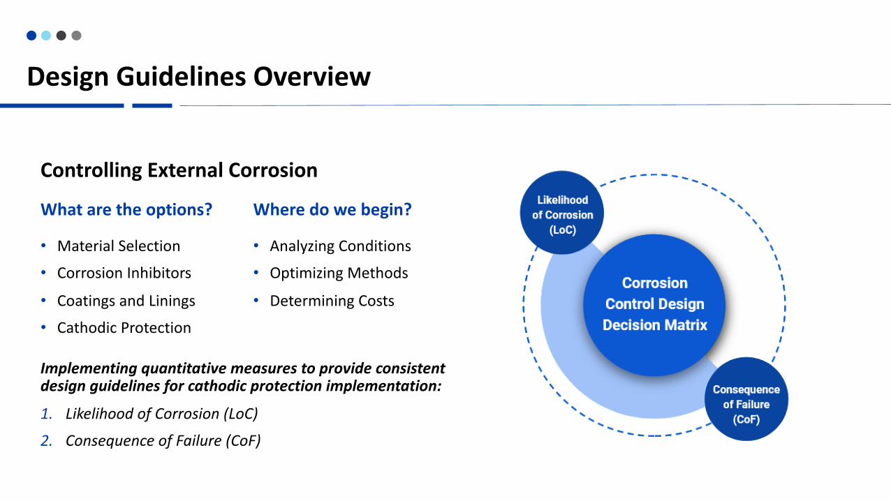
Controlling External Corrosion
• Material Selection
• Corrosion Inhibitors
• Coatings and Linings
• Cathodic Protection
What are the options?
• Analyzing Conditions
• Optimizing Methods
• Determining Costs
Where do we begin?
Implementing quantitative measures to provide consistent design guidelines for cathodic protection implementation:
1. Likelihood of Corrosion (LoC)
2. Consequence of Failure (CoF)

Likelihood of Corrosion Factors (LoC)
• Point-rated scales for each parameter with total available points ranging 0-50
• Provides framework for uniform soil sampling and analysis
• ASTM Standardization is required for uniform analysis
• Stray Current Analysis complements this process• Severe • Moderate• No Exposure
Soil Corrosivity Rating

Required Field Data
• pH (ASTM G51)• Measurements shall be collected by jar sampling nearest the
proposed pipe depth
• Soil Resistivity (ASTM G57, ASTM G187)• Soil borings shall be collected nearest the proposed pipe depth
• Redox Potential (ASTM D1498)• Measurements shall be collected by jar sampling nearest the
proposed pipe depth
• Soil Type • Soil classification(s) and groundwater level shall be determined
nearest the proposed pipe depth and alignment
• Chloride Content (ASTM D512)• Water soluble chloride content shall be determined by chloride
ion extraction using acceptable industry methodology prior to testing.
Soil Condition Analysis

CONSEQUENCE OF FAILURE
Consequences of Failure (CoF) are critical factors relating to operational reliability, maintainability, and subsequent effects on the distribution system
Four Critical ParametersPoint-rated scales for each parameter with total available points ranging 4-50
I. Pipe Diameter
II. Storage and/or Redundancy
III. Reparability
IV. Consequence to Distribution
Defining Subjective Ranges
• The overarching goal of this effort is to create objective scoring criteria• Reparability Definitions• Consequence to Distribution
(CtD)
PARAMETER RANGE VALUE
36" to 60" 10
28" to 32" 6
16" to 24" 4
4" to 12" 2
No Redundancy 5
No Storage 3
Yes 0
Prohibitive 20Difficult 12
Moderate 5Routine 0
Severe 5
Moderate 3
Appreciable 0
Stor
age
and/
or
Redu
ndan
cy
Cons
eque
nce
to
Dist
ribut
iuon
Repa
riabi
lity
Pipe
Ser
vice

Corrosion Control Decision Matrix
• A risk scoring matrix adapted from The Design Decision Model [Corrpro & DIPRA]. (2018)
• This tool outlines the standard design guidelines unless more stringent requirements are necessitated based on a qualified corrosion professional’s analysis
1 2 3 4 5 6 7 8 9 # # # # # # # # # # # # # # # # # # # # # # # # # # # # # # # # # # # # # # # # #
Cons
eque
nce
of F
ailu
re (C
oF)
Likelihood of Corrosion501 10 20 30 40
50
10
1
20
30
40Design Guidelines
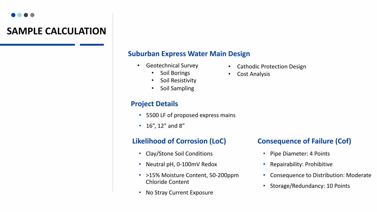
SAMPLE CALCULATION
Suburban Express Water Main Design
• 5500 LF of proposed express mains
• 16”, 12” and 8”
• Geotechnical Survey• Soil Borings• Soil Resistivity• Soil Sampling
Project Details
Likelihood of Corrosion (LoC)• Clay/Stone Soil Conditions
• Neutral pH, 0-100mV Redox
• >15% Moisture Content, 50-200ppm Chloride Content
• No Stray Current Exposure
Consequence of Failure (Cof)• Pipe Diameter: 4 Points
• Repairability: Prohibitive
• Consequence to Distribution: Moderate
• Storage/Redundancy: 10 Points
• Cathodic Protection Design• Cost Analysis

Sample Calculations
Likelihood of Corrosion (LoC) & Consequence of Failure (Cof) Analysis
• LoC: 26 Points
• CoF: 39 Points
1 2 3 4 5 6 7 8 9 # # # # # # # # # # # # # # # # # # # # # # # # # # # # # # # # # # # # # # # # #
Cons
eque
nce
of F
ailu
re (C
oF)
Likelihood of Corrosion501 10 20 30 40
50
10
1
20
30
40
Calibrating Expectations
• Establishing Proof-of-Concept
• Maximizing ROI

Design Submittal Process
Submittal I Submittal IIStray Current Submittal(1) All pipe sizes, submit the completed
Cathodic Protection Submittal I form along with:
i. Preliminary plans showing the pipeline alignment
ii. Proposed soil boring locations
(1) All pipe sizes, submit plans and specifications with corrosion control and stray current control measures.
(1) All pipe sizes, submit the completed Cathodic Protection Submittal II form including:
i. Soil Condition Analysis
ii. Stray Current Analysis
iii. Existing Pipe Analysis
iv. External Corrosion Control Requirements

LIVE POLL QUESTION #2
What challenge does your organization primarily experience in addressing corrosion control methods?
a) Identifying appropriate methods of corrosion controlb) Developing design guidelines for implementing corrosion
control methodsc) Identifying corrosion prone areas prior to failured) Securing stakeholder and upper management approval for
integration of corrosion control methodse) All of the above

CONTINUING WORK

CONTINUING WORKI. Capital ProjectsExternal Corrosion Control Rehabilitation
Bidding and Field ConstructionICCP Tank Upgrades
Inclusion of CP Design from Project Inception
II. Specification Development
III. Technology Improvements
External Corrosion Control Design ManualUnified Specifications and DetailsCorrosion Control Decision Framework
Continued Adoption of Industry Best Practices
Unmanned Aerial System (UAS) Facility InspectionsRemote Monitoring Unit (RMU) UpgradesCorrosion Field Testing