Embed Size (px)
Citation preview
Research Report 1400
0CO) Training Program Development000 for the M249 Bipod-Mounted
'Squad Automatic Weapon (SAW))
James E. FushaMellonics Systems Development Division
Litton Systems, Inc.
Thomas J. ThompsonArmy Research Institute
ARI Field Unit at Fort Benning, GeorgiaTraining Research Laboratory
IT.. IELECTE
1~. ~]jj~J.MAY 13 1987k E
U. S. Army
Research Institute for the Behavioral and Social Sciences
February 1985
Approvitd for public release: distribution unlimited.
87 5 30 064
UNCLASSIFIEDSECURITY CLASSIFICATION OF THIS PAGE ("en Dt. Entered)
R DREAD INSTRUCTIONSREPORT DOCUMENTATION PAGE I BEFORE COMPLETING FORM
1. REPORT NUMBER 2. GOVT ACCESSION NO. 3. CIPIENT'S CATALOG NUMBER
-ARI Research Report 1400 AIT ~4. TITLE (end Subtitle) S. TYPE OF REPORT & PERIOD COVERED
Final Report
TRAINING PROGRAM DEVELOPMENT FOR THE M249 June 1983 - June 1984
BIPOD MOUNTED SQUAD AUTOMATIC WEAPON (SAW) 6. PERFORMING ORG. REPORT NUMBER
7. AUTHOR(&) S. CONTRACT OR GRANT NUMBER(-)
James E. Fusha (Litton) and MDA 903-80-C-0545
Thomas J. Thompson (ARI)
9. PERFORMING ORGANIZATION NAME AND ADDRESS 10. PROGRAM ELEMENT. PROJFtT. TASKLitton .c AREA & WORK UNIT NUMBqS
to Me2lonics 2Q263743A794
P.O. Box 2498 3231 102Fort Benning, GA 31905 5710
I1. CONTROLLING OFFICE NAME AND ADDRESS 12. REPORT DATE
U.S. Army Research Institute for the Behavioral February 1985and Social Sciences 13. NUMBER OF PAGES
5001 Eisenhower Avenue, Alexandria, VA 22333-5600 98
14. MONITORING AGENCY NAME & AODRESS(IU dliferent from Controlllng OffIce) IS. SECURITY CLASS. (of this repott)
ARI Field Unit UnclassifiedP.O. Box 2086 1s. OECLASSIFICATION/DOWNGRADING
Fort Benning, GA 31905 SCHEDULE
16. DISTRIBUlTION STATEMENT (of this Report)
Approved for public release; distribution unlimited
17. DISTRIBUTION STATEMENT (of the abstract entered In Block 20, If diffetent from Repott)
18. SUPPLEMENTARY NOTES
Seward Smith, Contracting Officer's Representative
19. KEY WORDS (Continue on reverse aIde It necesoary and Identify by block number)Familiarization firing Zeroing procedures Shot group dispersionSquad automatic weapon Target engagement High/low gas setting
Test firing Range configurations Trajectory
Qualification standards Burst fire Qualification firing
20. ABSTR ACT (Coatfoue a revere. ed It n "eaesl and IdentIfy by block number)
) "-.- -Research was conducted to develop a program of instruction {P0.IY)that
includes both familiarization and qualification courses of fire for ":he squadautomatic weapon (SAW). An extensive analysis of test fire data, firing tech-
"niques and procedures, weapon characteristics and training requirements was
performed. Major findings were: (1) successful engagement of targets at
ranges greater than 400 meters is limited by system design deficiencies,
(2) the most effective beaten zone is created by firing rapid two to three
round bursts with short intervals between bursts for reacquiring (Continued)
DD I AN ,3 1473 EDITION OF I HOV 65 IS OBSOLETE UNCLASSIFIED
i SECURITY CLASSIFICATION OF THIS PAGE ("on D1-l Entered)
UNCLASSIFIED
'CUITY CLAS$iiICATION or T $ II"A0.(Wh . D.t. K.-.-..)
ARI Research Report 1400
19. (Continued)
AmmunitionBallisticsTraining development (interim)FC 23-10
20. (Continued)
, b and relaying on the target, (3) the M856 tracer round is impossible to ob-KI serve from behind the sights, (4) the most effective position for firing
the SAW is the M60 posiLion published in FM 23-67 (1964), (5) the SAW shouldbe zeroed using single shot fire at a range of 10 meters with a 500 meterrange setting on the sight, (6) SAW transition firing can be conducted on arecord fire range (TRAINFIRE Qualification), a rifle field fire range, or amachinegun transition range, (7) both M855 and M193 ammunition are suitablefor SAW training; however, ballistic variances preclude mixing of trainingammunition and limit use of M193 ammunition to ranges of 300 meters andless.
Accession For
DTIC TABUnannounced F]Justificatio
Distribution/ QUALITY
I__Availability CodesAva il and/or
Dist Special
AU S
UNCLASSIFIEDS] rCUPRITY CLASSIrICATIO. Or THIS PAGC(W?%on DO(& Cn,.,.d)
Research Report 1400
Training Program Developmentfor the M249 Bipod-Mounted
Squad Automatic Weapon (SAW)
James E. FushaMellonics Systems Development Division
Litton Systems, Inc.
Thomas J. ThompsonArmy Research Institute
Submitted bySeward Smith, Chief
ARI Field Unit at Fort Benning, Georgia
Approved as technically adequateand submitted for publication byDonald F. Haggard, Acting DirectorTraining Research Laboratory
U.S. ARMY RESEARCH INSTITUTE FOR THE BEHAVIORAL AND SOCIAL SCIENCES
5001 Eisenhower Avenue, Alexandria, Virginia 22333
Office, Deputy Chief of Staff for PersonnelDepartment of the Army
r IFebruary 1985
Army Project Number Education and Training20263743A794
Approved for public roleaso disltrbution unhimlod.
JIii
ARI Research Reports and Technical Reports are intended for sponsors ofR&D tasks and for other research and military ,gencies. Any findings readyfor implementation at the time of publication are presented in the last partof the Brief. Upon completion of a major phase of the task, formal recom-mendations for official action normally are conveyed to appropriate militaryagencies by briefing or Disposition Form.
iv
11 "'. r K
FOREWORD
The Squad Automatic Weapon (SAW) is a new lightweight, one-man portableautomatic weapon that is capable of delivering a large volume of sustained,and lethal fire on a target. It provides the infantry squad with improvedsuppressive fire and a high volume of close and continuous assault firenecessary to better accomplish its mission. Beginning in 1984, the SAWis being fielded to replace the MI6Al rifles carried by the two members ofthe infantry squad who are designated as automatic riflemen. In support ofthe USAIS, the U.S. Army Research Institute has initiated training developmentresearch for the SAW weapon system. One of the purposes of the ARI researchis to develop a Program of Instruction (POI) that includes courses of firefor both familiarization and qualification.
EDGAR M. JOHNSON* Technical Director
N
v
JA 7t '
F
TRAINING PROGRAM DEVELOPMENT FOR THE M249BIPOD MOUNTED SQUAD AUTOMATIC WEAPON (SAW)
EXECUTIVE SUMMARY
Requirement:
Beginning in 1984, the SAW is being fielded to replace the M16Al riflescarried by the two members of the infantry rifle squad who are designated asautomatic riflemen. Accordingly, the US Army Infantry School (USAIS) hasinitiated research to develop training materials and programs of instruction(POI) to accompany the fielding of the SAW. In support of the USAIS, the USArmy Reoearch Institute (ARI) has conducted research to determine firingcharacteristics and weapon system performance as part of the interim trainingprogram development. The primary purpose of the ARI research to date has beento identify effective training procedures to meet the Army requirements andSAW capabilities in order to field a program compatible with training facilitiesand the capabilities of the SAW.
Procedure:
A series of test firings by skilled marksmen was conducted to determineweapon characteristics, fire dispersion patterns, ammunition performancedifferences, and overall system performances. The tests were conducted from arigid bench rest mount at ranges out to 300 meters, at the 10-meter zeroingrange, and from the bipod mount at anticipated operational ranges out to900 meters. Experiments were conducted to determine proper holding techniques,optimum burst size, bullet trajectory, variances between ammunition types,automatic fire beaten zone capabilities, and probability of target hit undertypical user conditions. Finally, an evaluation of SAW performance capabilitieswas undertaken to prepare trainers for its introduction and to determinewhether the weapon could meet the standards set for it based on developmentaltesting criteria. Major objectives were to:
o Develop a Program of Instructiono Develop Familiarization Course of Fireo Develop Qualification Course of Fire
Findings:
Familiarization and qualification marksmanship instructional programswere developed. As part of the program implementation process, a varietyof range configurations, targets, and training materials were evaluated.Procedures and materials in the area of instruction and performance criteriawere developed. Further, constraints that hinder performance and the imple-mentation process were identified, together with areas of future researchhaving the potential to partially overcome the effects of these constraints.
o - Utilization of Findings:
The interim programs for basic marksmanship training with the bipodmounted squad automatic weapon reported herein have been approved for adoptionArmy-wide by the U.S. Army Infantry School (as proponent). Refinements to theweapon system and process of implementation/evaluation are currently beingaddressed.
vii
TRAINING PROGRAM DEVELOPMENT FOR THE M249BIPOD MOUNTED SQUAD AUTOMATIC WEAPON (SAW)
CONTENTSPage
INTRODUCTION ...... .... ............................. 1
Background..... .... .. ........ . . . . . 1Purpose ....... .. ........................... . . . . 1Objectives. .. .... . ..... . ...... . .... . . 2
METHODS ........ ...... .............................. 3
Results ....... .... ............................. . 4
DISCUSSION .... .............................. 26
Historical ...... ....... ....... ....... 26Weapon Considerations .. . .......................... 28Range Considerations ....... .... ...................... 31Current Interim Training Development ..... .............. .. 32Accuracy ...... .... ............................ . 35Training Program Development ...... .................. ... 40Constraints in Program Development ....... ............... 43
CONCLUSIONS AND RECOMMENDATIONS ...... .................. ... 48
Conclusions ....... ... .......................... . 48Recommendations ....... ... ......................... . 49Potential Areas for Further Study ..... ................ ... 50
REFERENCES ...... ....... ............................ 53
APPENDIX A. SAW TEST FIRE PLAN ....... .................. A-1B. SAW TEST FIRE TABLES B-1 THROUGH B-11 .... ......... B-1C. ARMY MARKSMANSHIP UNIT SAW FIRING TEST - COMMENTS . . . C-1
LIST OF TABLES
Table 1. SAW 300 Meter Bench Rest Firing for Field Zero .... 4
2. SAW 10 Meter Bench Rest Firing for Point-of-Aim/
Point-of-Impact Determination ...... ............. 5
3. SAW 10 Meter Bench Rest Firing for Point-of-Aim/Point-of-Impact Determination of Ammunition Differences
4. 100 Meter Bench Rest Group Dispersion .... ......... 7
5. 100 Meter Bench Rest Mean Group Dispersion ... ...... 7
6. 300 Meter Single Shot Groups SAW vs. Mann Barrel . . . 8
7. SAW Bench Rest Firing SS109 Ammunition Normal vs.
High Gas Setting ...... ....................... 9
ix
CONTENTS (Continued)Page
8. SAW 10 Meter Zeroing Performance ........... 10
9. SAW 10 Meter Bipod Holding Techniques M60 and Two-Hand Hold on Grip ..... ................... 11
10. SAW 10 Meter Bipod Pressure Single Shot, Five Shot
Group ....... ..................... . . . . 12
11. M193 Ammunition and SS109 Ammunition Five Round Burst 16
12. SS109 Ammunition 10 Round Burst .... ............ ... 19
13. SAW 700, 800, 900 Meter Firing . ........... 20
14. Summary of SAW Burst Fire ............... 21
15. Ml6AI Riflt Record Fire Range .... ............. ... 25
16. SAW Training Tasks ..... .................. 33
17. Table of Contents of Field Circular 23-10 ....... 44
LIST OF FIGURES
Figure 1. 15 shot group centers at 300 meters ..... .......... 6
2. Test Fire Target - Ranges 100 - 900 Meters . ...... . 13
3. Test Fire Target - Ranges 100 - 900 Meters ... ....... 14
4. Scaled Test Fire Target ..... ................ ... 15
5. Rounds Captured 6" x 6" Target .... ............ ... 17
6. Silhouette Target Hits ...... ................ ... 18
7. MI6AI Rifle Record Fire Range Firing Tables ........ ... 23
8. SS109 Ball Trajectory ...... ................ ... 36
9. SAW Trajectory - SS109 Ball .... ............... 37
10. A ballistic comparison of M193 and XM855/XM856(SS109/LIIO) ammunition ........ ................ 38
11. Burst Fire Performance Rounds Captured on 6' x 6" Panel 41
12. Burst Fire Performance Silhouette flits .. ........ ... 42
13. SAW Qualification & Familiarization Training ProgramsOverview ... .. ...................... 46
INTRODUCTION
Background
Development of the Squad Automatic Weapon (SAW) began in 1971 with amateriel need document which was subsequently accepted by the Department ofthe Army in 1973 (Niewenhous, 1982). Developmental testing of candidateweapons began in 1974 at the US Army Aberdeen Proving Ground and continuedthrough the 1970s. In May of 1980, the XM249, in 5.56mm caliber was selectedas the US Army's SAW. At the same time, the Belgian SS109 ball and LifOtracer cartridges, which were later designated XM855/XM856 respectively, wereselected for use in the weapon instead of the standard M193/M196 ball andtracer combination available in the inventory. The newer ammunition wasdesigned to be compatible with the I in 7 inch twist barrel of the SAW and theM16A2 rifle as well, which is to be fielded as a replacement for the currentstandard Ml6Al. The ammunition and barrel combination was designed to providea greater effective range for these weapons.
APurpose
Beginning in 1984, the SAW is being fielded to replace the Ml6Al riflescarried by the two members of the infantry rifle squad who are designated asautomatic riflemen. Accordingly, the US Army Infantry School (USAIS) hasinitiated research to develop training materials and programs of instruction(POI) to accompany the fielding of the SAW. In support of the USAIS, the USArmy Research Institute (ARI) has conducted research to determine firingcharacteristics and weapon system performance as part of the interim trainingprogram development. The primary purpose of the ARI research to date has beento identify effective training procedures to meet the Army requirements andSAW capabilities in order to field a program compatible with training facilitiesand the capabilities of the SAW.
The Mellonics Systems Development Division of Litton Systems, Inc.,under contract to ARI, has been conducting research supported by USAIS throughthe Fort Benning ARI Field Unit. This research has involved test firing, datacollection, and the determination of optimum firing techniques and procedures,as well as identification of SAW peculiar characteristics and trainingrequirements. This report presents research findings which resulted fromfield experimentation and discusses their implications for time and costeffective marksmanship training with the SAW. The product of this research isFC 23-10, Basic Marksmanship Training Bipod Mounted Squad Automatic Weapon(SAW), dated March 1984.
The process of developing the SAW marksmanship training programs involvedmuch more than simply test firing the M249 SAW to determine weapon capabilitiesin order to provide new programs of instruction for training personnel.
Results of research include outlined efforts that supported the development/implementation process. For clarity of presentation, these interrelatedefforts are detailed within the areas of equipment, ammunition, and rangeconfiguration.
objectives
Specific objectives of this research include:
- Development of a Program of Instruction (POI) for the Squad AutomaticWeapon.
- Development of a course of fire for familiarization for the SquadAutomatic Weapon.
- Development of a course of fire for qualification for the SquadAutomatic Weapon.
In order to pursue these objectives, engineering and service tests of theSAW were reviewed to better understand its characteristics, capabilities, andexpected performance. In addition, liaison with the Fire Control and SmallCaliber Weapon Systems Laboratory, U.S. Army Research and Development Commandproduced on-site visits and working conferences with engineers and personnelresponsible for SAW system quality control and acceptance.
N
I,
2
~~~N NC .
METHODS
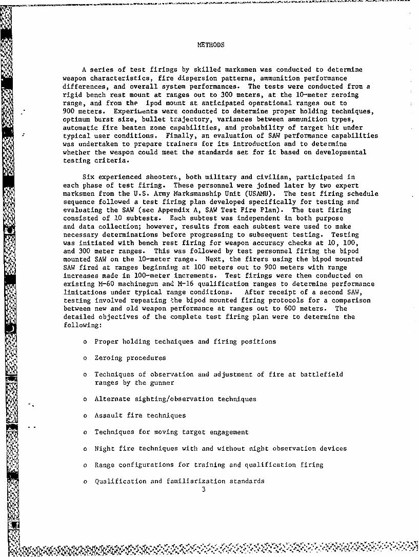
A series of test firings by skilled marksmen was conducted to determineweapon characteristics, fire dispersion patterns, ammunition performancedifferences, and overall system performances. The tests were conducted from arigid bench rest mount at ranges out to 300 meters, at the 10-meter zeroingrange, and from the ipod mount at anticipated operational ranges out to900 meters. ExperiLuents were conducted to determine proper holding techniques,optimum burst size, bullet trajectory, variances between ammunition types,automatic fire beaten zone capabilities, and probability of target hit undertypical user conditions. Finally, an evaluation of SAW performance capabilitieswas undertaken to prepare trainers for its introduction and to determinewhether the weapon could meet the standards set for it based on developmentaltesting criteria.
Six experienced shooter&., both military and civilian, participated ineach phase of test firing. These personnel were joined later by two expertmarksmen from the U.S. Army Marksmanship Unit (USAMU). The test firing schedulesequence followed a test firing plan developed specifically for testing andevaluating the SAW (see Appendix A, SAW Test Fire Plan). The test firingconsisted of 10 subtests. Each subtest was independent in both purposeand data collection; however, results from each subtest were used to makenecessary determinations before progressing to subsequent testing. Testingwas initiated with bench rest firing for weapon accuracy checks at 10, 100,and 300 meter ranges. This was followed by test personnel firing the bipodmounted SAW on the 10-meter range. Next, the firers using the bipod mountedSAW fired at ranges beginning at 100 meters out to 900 meters with rangeincreases made in 100-meter increments. Test firings were then conducted on
n existing M-60 machinegun and M-16 qualification ranges to determine performancelimitations under typical range conditions. After receipt of a second SAW,testing involved repeating the bipod mounted firing protocols for a comparisonbetween new and old weapon performance at ranges out to 600 meters. Thedetailed objectives of the complete test firing plan were to determine thefollowing:
o Proper holding techniques and firing positions
o Zeroing procedures
" Techniques of observation and adjustment of fire at battlefieldranges by the gunner
o Alternate sighting/observation techniques
o Assault fire techniques
o Techniques for moving target engagement
o Night fire techniques with and without night observation devices
o Range configurations for training and qualification firing
o Qualification and familiarization standards3
r W
Results
The SAW test firing that took place at targets at ranges of 10 meters
and 100 meters from a stabilized bench rest (rigid mount) was conducted to
determine SAW performance under conditions that would allow near optimum
holding and stability. This firing condition has typically shown the maximum
capabilities of the weapon without the firer's intervention. Test firingincluded single shot group development and burst fire at 10, 100, and 300-meter
ranges. The tests were conducted to determine firing characteristics,differences in single shot firing versus burst fire techniques, ammunitioncharacteristics (SS109, LIIO, M193, and M196), and weapon performance at highand low gas settings.
Initial firing began with single shot, five round groups from a benchiest mount at a known distance range of 300 meters. The purpose of this
firing was to establish a field zero for the squad automatic weapon. Thesighting system is designed to allow range increases in one hundred meter
increments between 300 and 1000 meters. The minimum range setting availablewas selected. It was also the maximum distance available on the firing range
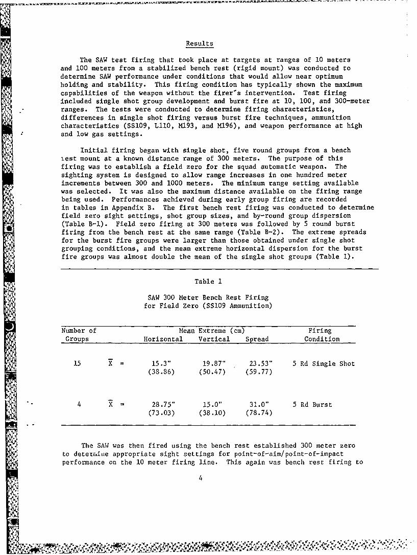
being used. Performances achieved during early group firing are recordedin tables in Appendix B. The first bench rest firing was conducted to determinefield zero sight settings, shot group sizes, and by-round group dispersion(Table B-l). Field zero firing at 300 meters was followed by 5 round burstfiring from the bench rest at the same range (Table B-2). The extreme spreadsfor the burst fire groups were larger than those obtained under single shotgrouping conditions, and the mean extreme horizontal dispersion for the burst
fire groups was almost double the mean of the single shot groups (Table 1).
Table 1
SAW 300 Meter Bench Rest Firing
for Field Zero (SS109 Ammunition)
Number of Mean Extreme (cm) Firing
Groups Horizontal Vertical Spread Condition
15 X 15.3" 19.87" 23.53" 5 Rd Single Shot
(38.86) (50.47) (59.77)
4 4 X 28,75" 15.0" 31.0" 5 Rd Burst(73.03) (38.10) (78.74)
The SAW was then fired using the bench rest established 300 meter zeroto detetriie appropriate sight settings for point-of-aim/point-of-impactperformance on the 10 meter firing line. This again was bench rest firing to
4
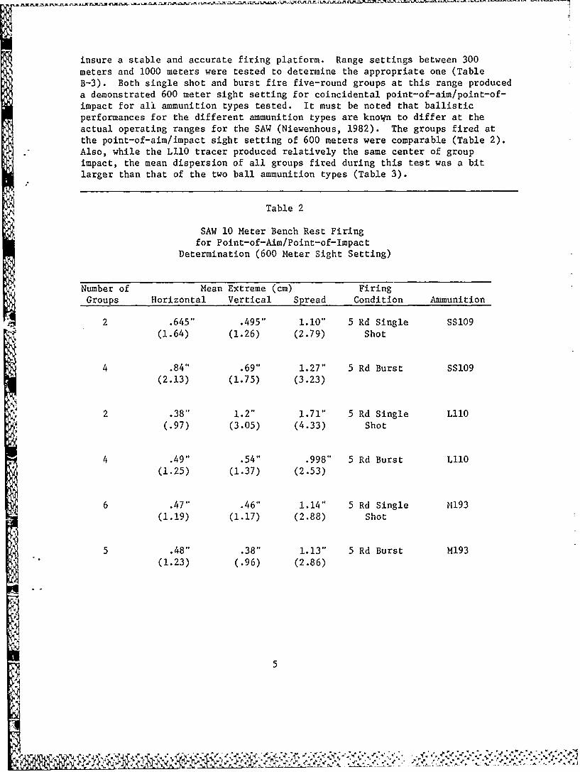
insure a stable and accurate firing platform. Range settings between 300meters and 1000 meters were tested to determine the appropriate one (TableB-3). Both single shot and burst fire five-round groups at this range produceda demonstrated 600 meter sight setting for coincidental point-of-aim/point-of-impact for all ammunition types tested. It must be noted that ballisticperformances for the different ammunition types are known to differ at theactual operating ranges for the SAW (Niewenhous, 1982). The groups fired atthe point-of-aim/impact sight setting of 600 meters were comparable (Table 2).Also, while the LllO tracer produced relatively the same center of groupimpact, the mean dispersion of all groups fired during this test was a bitlarger than that of the two ball ammunition types (Table 3).
Table 2
SAW 10 Meter Bench Rest Firingfor Point-of-Aim/Point-of-Impact
Determination (600 Meter Sight Setting)
Number of Mean Extreme (cm) FiringGroups Horizontal Vertical Spread Condition Ammunition
2 .645" .495" 1.10" 5 Rd Single SS109(1.64) (1.26) (2.79) Shot
4 .84" .69" 1.27" 5 Rd Burst SS109(2.13) (1.75) (3.23)
2 .38" 1.2" 1.71" 5 Rd Single Lll0(.97) (3.05) (4.33) Shot
4 .49" .54" .998" 5 Rd Burst L11O
(1.25) (1.37) (2.53)
6 .47" .46" 1.14" 5 Rd Single M193(1.19) (1.17) (2.88) Shot
5 .48" .38" 1.13" 5 Rd Burst M193(1.23) (.96) (2.86)
5
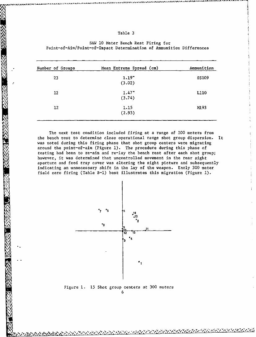
Table 3
SAW 10 Meter Bench Rest Firing forPoint-of-Aim/Point-of-Impact Determination of Ammunition Differences
Number of Groups Mean Extreme Spread (cm) Ammunition
23 1.19" SS109
(3.02)
12 1.47" LIO
(3.74)
12 1.15 M193(2.93)
The next test condition included firing at a range of 100 meters fromthe bench rest to determine close operational range shot group dispersion. Itwas noted during this firing phase that shot group centers were migratingaround the point-of-aim (Figure 1). The procedure during this phase oftesting had been to re-aim and re-lay the bench rest after each shot group;however, it was determined that uncontrolled movement in the rear sightaperture and feed tray cover was altering the sight picture and subsequentlyindicating an unnecessary shift in the lay of the weapon. Early 300 meterfield zero firing (Table B-l) best illustrates this migration (Figure 1).
4
Figure 1. 15 Shot group centers at 300 meters
6
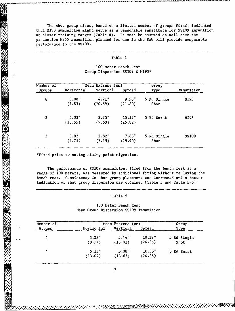
The shot group sizes, based on a limited number of groups fired, indicatedthat M193 ammunition might serve as a reasonable substitute for SS109 ammunitionat closer training ranges (Table 4). It must be assumed as well that the
production M855 ammunition planned for use in the SAW will provide comparableperformance to the SS109.
Table 4
100 Meter Bench RestGroup Dispersion SS109 & M193*
Number of Mean Extreme (cm) GroupGroups Horizontal Vertical Spread Type Ammunition
6 3.08" 4.21" 8.58" 5 Rd Single M193(7.83) (10.69) (21.80) Shot
3 5.33" 3.75" 10.17" 5 Rd Burst M193(13.55) (9.53) (25.82)
3 3.83" 2.82" 7.83" 5 Rd Single SS109(9.74) (7.15) (19.90) Shot
*Fired prior to noting aiming point migration.
The performance of SS109 ammunition, fired from the bench rest at arange of 100 meters, was measured by additional firing without re-laying thebench rest. Consistency in shot group placement was increased and a betterindication of shot group dispersion was obtained (Table 5 and Table B-5).
Table 5
100 Meter Bench RestMean Group Dispersion SS109 Ammunition
Number of Mean Extreme (cm) GroupGroups Horizontal Vertical Spread Type
4 3.38" 5.44" 10.38" 5 Rd Single(8.57) (13.81) (26.35) Shot
4 5.13" 5.38" 10.38" 5 Rd Burst(13.02) (13.65) (26.35)
44 7
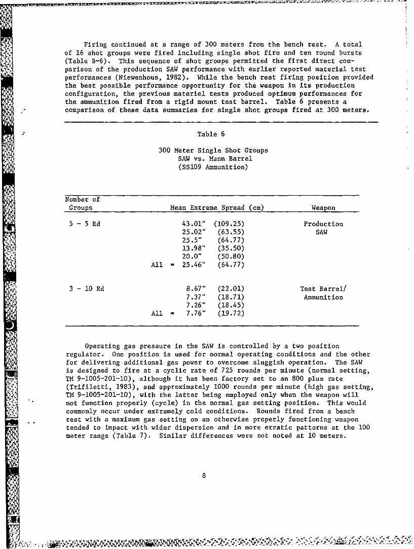
Firing continued at a range of 300 meters from the bench rest. A totalof 16 shot groups were fired including single shot fire and ten round bursts(Table B-6). This sequence of shot groups permitted the first direct com-parison of the production SAW performance with earlier reported materiel testperformances (Niewenhous, 1982). While the bench rest firing position providedthe best possible performance opportunity for the weapon in its productionconfiguration, the previous materiel tests produced optimum performances forthe ammunition fired from a rigid mount test barrel. Table 6 presents acomparison of these data summaries for single shot groups fired at 300 meters.
Table 6
300 Meter Single Shot GroupsSAW vs. Mann Barrel(SSl09 Ammunition)
Number ofGroups Mean Extreme Spread (cm) Weapon
5 - 5 Rd 43.01" (109.25) Production25.02" (63.55) SAW25.5" (64.77)13.98" (35.50)20.0" (50.80)
All = 25.46" (64.77)
3 - 10 Rd 8.67" (22.01) Test Barrel/7.37" (18.71) Ammunition7.26" (18.45)
All = 7.76" (19.72)
"I
Operating gas pressure in the SAW is controlled by a two positionregulator. One position is used for normal operating conditions and the otherfor delivering additional gas power to overcome sluggish operation. The SAWis designed to fire at a cyclic rate of 725 rounds per minute (normal setting,TM 9-1005-201-10), although it has been factory set to an 800 plus rate(Trifiletti, 1983), and approximately 1000 rounds per minute (high gas setting,TM 9-1005-201-10), with the latter being employed only when the weapon willnot function properly (cycle) in the normal gas setting position. This would
A' commonly occur under extremely cold conditions. Rounds fired from a benchrest with a maximum gas setting on an otherwise properly functioning weapontended to impact with wider dispersion and in more erratic patterns at the 100meter range (Table 7). Similar differences were not noted at 10 meters.
8
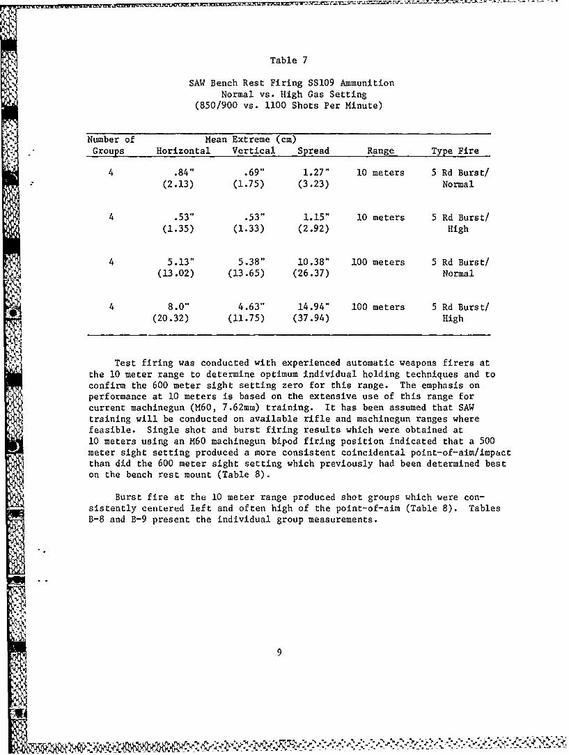
Table 7
SAW Bench Rest Firing SS109 AmmunitionNormal vs. High Gas Setting
(850/900 vs. 1100 Shots Per Minute)
Number of Mean Extreme (cm)Groups Horizontal Vertical Spread Range Type Fire
4 .84" .69" 1.27" 10 meters 5 Rd Burst/(2.13) (1.75) (3.23) Normal
4 .53" .53" 1.15" 10 meters 5 Rd Burst/(1.35) (1.33) (2.92) High
4 5.13" 5.38" 10.38" 100 meters 5 Rd Burst/(13.02) (13.65) (26.37) Normal
4 8.0" 4.63" 14.94" 100 meters 5 Rd Burst/(20.32) (11.75) (37.94) High
Test firing was conducted with experienced automatic weapons firers atthe 10 meter range to determine optimum individual holding techniques and toconfirm the 600 meter sight setting zero for this range. The emphasis onperformance at 10 meters is based on the extensive use of this range forcurrent machinegun (M60, 7.62mm) training. It has been assumed that SAWtraining will be conducted on available rifle and machinegun ranges wherefeasible. Single shot and burst firing results which were obtained at10 meters using an M60 machinegun bipod firing position indicated that a 500meter sight setting produced a more consistent coincidental point-of-aim/impactthan did the 600 meter sight setting which previously had been determined beston the bench rest mount (Table 8).
Burst fire at the 10 meter range produced shot groups which were con-sistently centered left and often high of the point-of-aim (Table 8). TablesB-8 and B-9 present the individual group measurements.
* 9
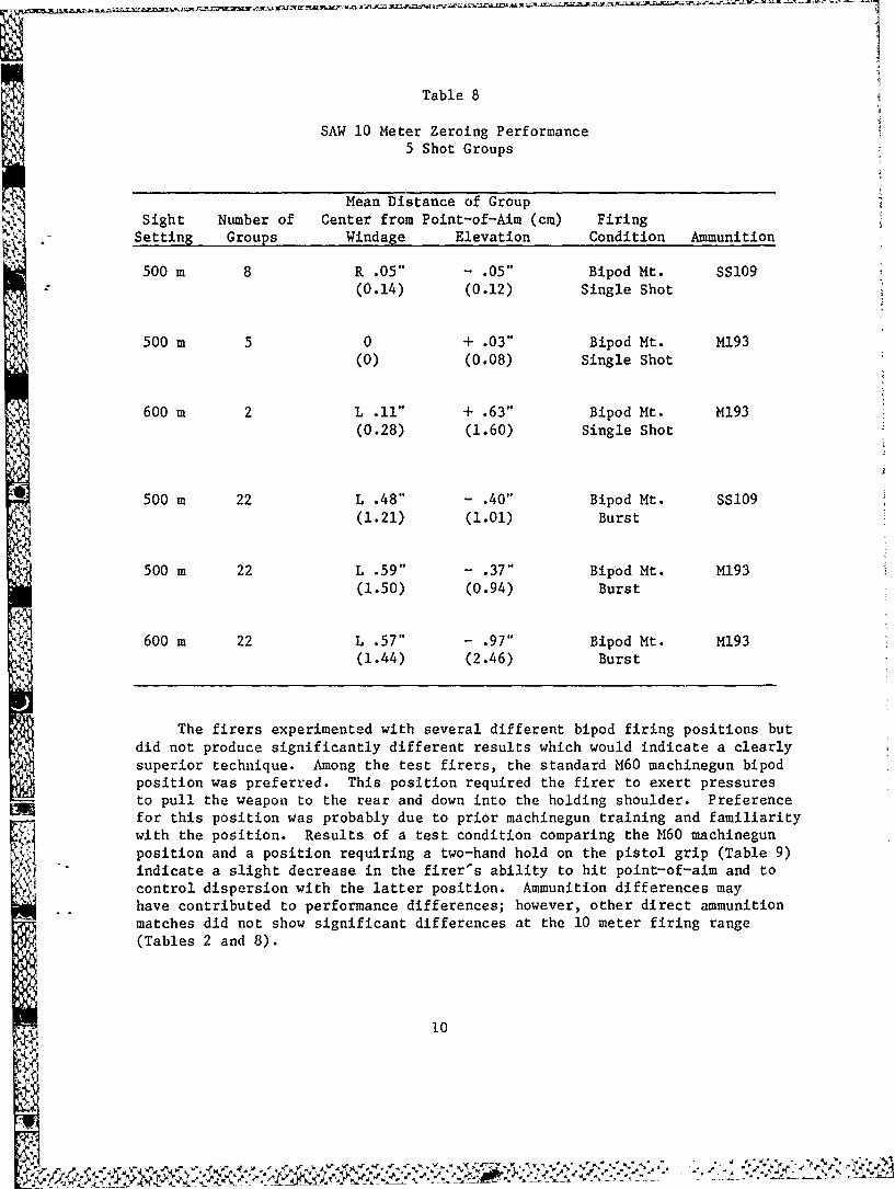
Table 8
SAW 10 Meter Zeroing Performance
5 Shot Groups
Mean Distance of GroupSight Number of Center from Point-of-Aim (cm) FiringSetting Groups Windage Elevation Condition Ammunition
500 m 8 R .05" - .05" Bipod Mt. SS109
(0.14) (0.12) Single Shot
500 m 5 0 + .03" Bipod Mt. M193
(0) (0.08) Single Shot
600 m 2 L .11" + .63" Bipod Mt. M193(0.28) (1.60) Single Shot
500 m 22 L .48" - .40" Bipod Mt. SS109(1.21) (1.01) Burst
500 m 22 L .59" - .37" Bipod Mt. M193(1.50) (0.94) Burst
600 m 22 L .57" - .97" Bipod Mt. M193(1.44) (2.46) Burst
The firers experimented with several different bipod firing positions butdid not produce significantly different results which would indicate a clearlysuperior technique. Among the test firers, the standard M60 machinegun bipodposition was preferred. This position required the firer to exert pressuresto pull the weapon to the rear and down into the holding shoulder. Preferencefor this position was probably due to prior machinegun training and familiaritywith the position. Results of a test condition comparing the M60 machinegunposition and a position requiring a two-hand hold on the pistol grip (Table 9)indicate a slight decrease in the firer's ability to hit point-of-aim and tocontrol dispersion with the latter position. Ammunition differences mayhave contributed to performance differences; however, other direct ammunitionmatches did not show significant differences at the 10 meter firing range(Tables 2 and 8).
10
4
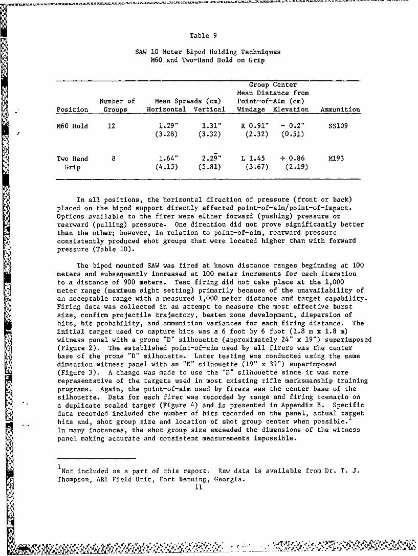
Table 9
SAW 10 Meter Bipod Holding TechniquesM60 and Two-Hand Hold on Grip
Group CenterMean Distance from
Number of Mean Spreads (cm) Point-of-Aim (cm)Position Groups Horizontal Vertical Windage Elevation Ammunition
M60 Hold 12 1.29" 1.31" R 0.91" - 0.2" SS109(3.28) (3.32) (2.32) (0.51)
Two Hand 8 1.64" 2.29" L 1.45 + 0.86 M193
Grip (4.15) (5.81) (3.67) (2.19)
In all positions, the horizontal direction of pressure (front or back)placed on the bipod support directly affected point-of-aim/point-of-impact.Options available to the firer were either forward (pushing) pressure orrearward (pulling) pressure. One direction did not prove significantly betterthan the other; however, in relation to point-of-aim, rearward pressureconsistently produced shot groups that were located higher than with forwardpressure (Table 10).
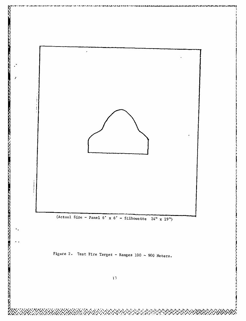
The bipod mounted SAW was fired at known distance ranges beginning at 100meters and subsequently increased at 100 meter increments for each iterationto a distance of 900 meters. Test firing did not take place at the 1,000meter range (maximum sight setting) primarily because of the unavailability ofan acceptable range with a measured 1,000 meter distance and target capability.Firing data was collected in an attempt to measure the most effective burstsize, confirm projectile trajectory, beaten zone development, dispersion ofhits, hit probability, and ammunition variances for each firing distance. Theinitial target used to capture hits was a 6 foot by 6 foot (1.8 m x 1.8 m)
-witness panel with a prone "D" silhouette (approximately 24" x 19") superimposed(Figure 2). The established point-of-aim used by all firers was the centerbase of the prone "D" silhouette. Later testing was conducted using the samedimension witness panel with an "E" silhouette (19" x 39") superimposed(Figure 3). A change was made to use the "E" silhouette since it was morerepresentative of the targets used in most existing rifle marksmanship trainingprograms. Again, the point-of-aim used by firers was the center base of the
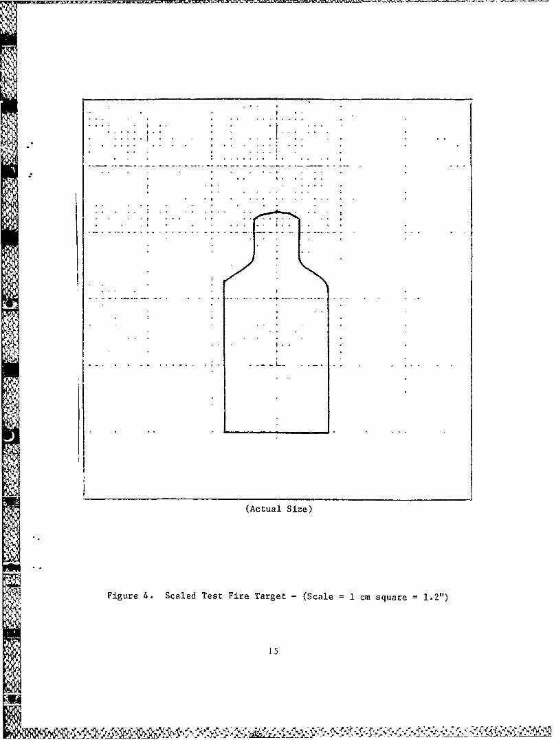
silhouette. Data for each firer was recorded by range and firing scenario ona duplicate scaled target (Figure 4) and is presented in Appendix B. Specificdata recorded included the number of hits recorded on the panel, actual tafget
hits and, shot group size and location of shot group center when possible.In many instances, the shot group size exceeded the dimensions of the witnesspanel making accurate and consistent measurements impossible.
iI
INot included as a part of this report. Raw data is available from Dr. T. J.Thompson, ARI Field Unit, Fort Benning, Georgia.
ii.
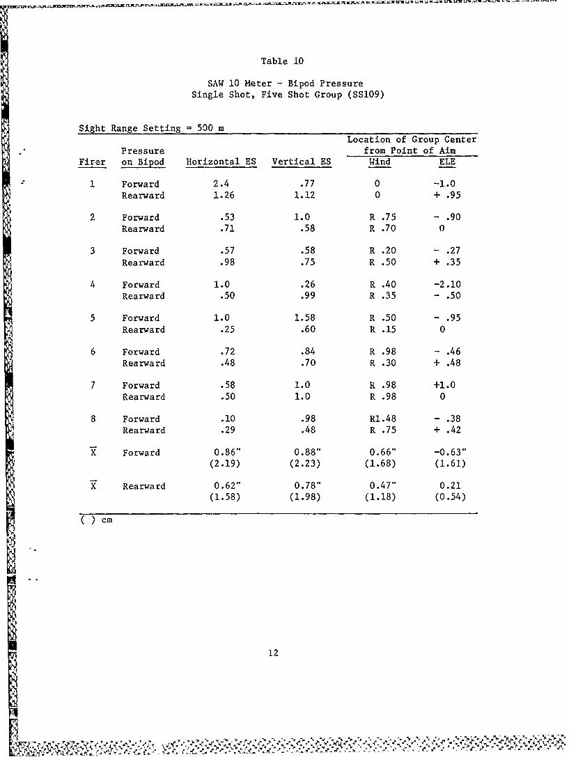
Table 10
SAW 10 Meter - Bipod PressureSingle Shot, Five Shot Group (SS109)
Sight Range Setting = 500 mLocation of Group Center
Pressure from Point of AimFirer on Bipod Horizontal ES Vertical ES Wind ELE
1 Forward 2.4 .77 0 -1.0Rearward 1.26 1.12 0 + .95
2 Forward .53 1.0 R .75 - .90Rearward .71 .58 R .70 0
3 Forward .57 .58 R .20 - .27
Rearward .98 .75 R .50 + .35
4 Forward 1.0 .26 R .40 -2.10
Rearward .50 .99 R .35 - .50
5 Forward 1.0 1.58 R .50 - .95
Rearward .25 .60 R .15 0
6 Forward .72 .84 R .98 - .46Rearward .48 .70 R .30 + .48
7 Forward .58 1.0 R .98 +1.0Rearward .50 1.0 R .98 0
8 Forward .10 .98 R1.48 - .38Rearward .29 .48 R .75 + .42
X Forward 0.86" 0.88" 0.66" -0.63"(2.19) (2.23) (1.68) (1.61)
X Rearward 0.62" 0.78" 0.47" 0.21(1.58) (1.98) (1.18) (0.54)
( ) cm
I-o
12
A%
II
(Actual Size - Panel 6' x 6' - Silhouette 24" x 19")
I..Figure 2. Test Fire Target - Ranges 100 - 900 Meters.
13
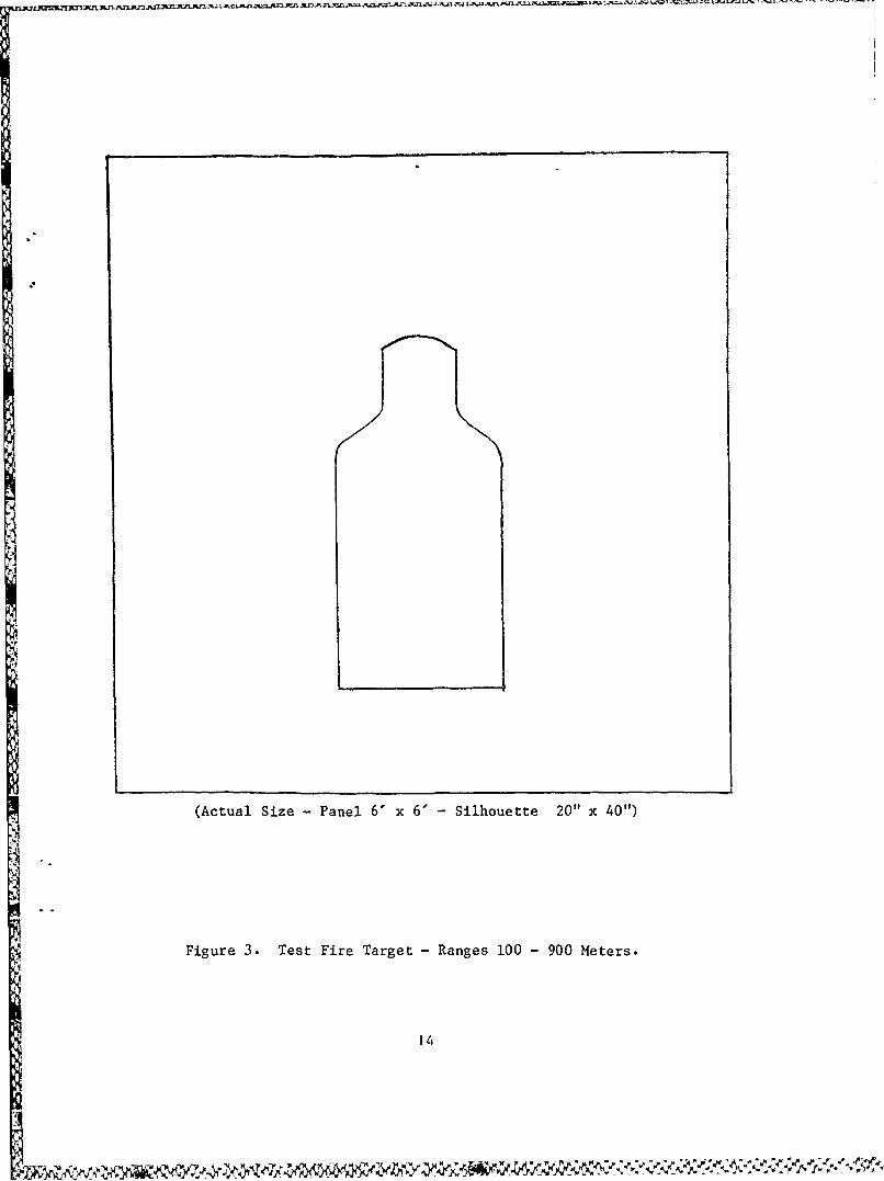
(Actual Size- Panel 6' x 6' - Silhouette 20" x 40")
Figure 3. Test Fire Target - Ranges 100 - 900 Meters.
14
* . I
K .. . . . . . .
II
Fiue4. SaedTs ire Tage - (Sal . msur ."
A
15
Initial test firing was conducted at ranges from 100 meters through 600meters. Firing scenarios included five round bursts and ten round burstsusing both SS109 and M193 ammunition for comparison. The number of rounds onwitness paper and target hit performance of the SS109 ammunition was marginallybetter than the MJ93 ammunition (Table 11 and Figures 5 and 6) at all rangesin this limited test. As firing distances increased, shot group sizes anddispersion rapidly enlarged to a point where many rounds in the burst from 5to 10 had a negative effect in relation to number of hits captured by thepanels as well as target silhouettes actually hit (Tables 11 and 12).
Table 11
M193 Ammunition5 rd Burst
Shot (W x 6')Range/Rounds Groups/Captured Hits Recorded Silhouette Hits
100 m/20 rds 4/4 20 (100%) 14 (70.0%)200 m/40 rds 8/8 40 (100%) 7 (17.5%)300 m/40 rds 8/3 28 (70.0%) 2 (5.0%)400 m/60 rds 12/2 23 (38.3%) 3 (5.0%)500 m/40 rds 8/2 12 (30.0%) 2 (5.0%)600 m/40 rds 8/0 3 (7.5%) 0 (0%)
SS109 Ammunition5 rd Burst
Shot (6' x 6')Range/Rounds Groups/Captured Hits Recorded Silhouette Hits
100 m/60 rds 12/12 60 (100%) 38 (63.3%)200 m/80 rds 16/13 60 (80.0%) 30 (37.5%)300 m/100 rds 20/13 61 (61.0%) 18 (18.0%)400 m/120 rds 24/12 62 (51.6%) 13 (10.8%)
500 m/40 rds 8/2 16 (40.0%) 2 (5.0%)600 m/40 rds 8/0 7 (17.5%) 2 (5.0%)
16
1001. M193SS1O9
90
80.
70
60
44 500
0
Co 4a)
tt
C.)
p 40
30
20
10
6 I0 1 26
Range (100 meter increments)
Figure 5. Rounds Captured - 6' x 6' Target
17
100- M193SS109
90
80
70
60
4j
40
20
40
30.\
20-
0 1
Range (100 meter increments)
Figure 6 Silhouette Target flits
18
Il
Table 12
SS109 Ammunition10 rd Burst
(6' x 6')Range/Rounds Rounds Captured Silhouette Hits
200 m/30 rds 24 (80.0%) 4 (13.2%)
300 m/30 rds 10 (33.3%) 3 (10.0%)
400 m/30 rds 5 (16.6%) 0 (0%)
500 m/20 rds 3 (15.0%) 0 (0%)
600 m/80 rds 19 (23.75%) 3 (3.75%)
Note: M193 ammunition was too scarce to replicate the 10 rd burst firing,given the poor results obtained with the SS109.
The next phase of testing involved firing at 700, 800, and 900 meterranges; however, due to the limited availability of M193 ammunition as well asits lack of stability at these greater ranges (Niewenhous, 1982), only SS109was fired. In an effort to better control the action of the weapon and theresulting dispersion of rounds caused by the high cyclic rate of operation,burst size for this phase was reduced from 5 round bursts to 2-3 round bursts.The test scenario required each of five firers to fire 30 rounds at a target(6 x 6' panel) at each range using a 2-3 round burst. After each burst, thefirer had to quickly re-lay on target, re-acquire his sight picture, and fireanother 2-3 round burst as he would have when providing suppressive fire.This process was repeated until all 30 rounds were expended. All five testfirers reported experiencing extreme difficulty in maintaining a target sight
picture during the firing sequence. Firers also reported that observation oftracers and/or impacting rounds in the target area was not possible. At theseranges, hits captured on witness paper and target hits could be best describedas random rather than as recognizable groups (Table 13).
-* ,
19
r~ '0
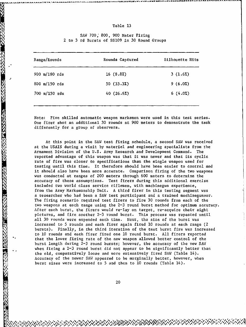
Table 13
SAW 700 800, 900 Meter Firing2 to 3 rd Bursts of SS109 in 30 Round Groups
Range/Rounds Rounds Captured Silhouette Hits
900 m/180 rds 16 (8.8%) 3 (1.6%)
800 m/150 rds 50 (33.3%) 9 (6.0%)
700 m/150 rds 40 (26.6%) 6 (4.0%)
Note: Five skilled automatic weapon marksmen were used in this test series.One firer shot an additional 30 rounds at 900 meters to demonstrate the taskdifferently for a group of observers.
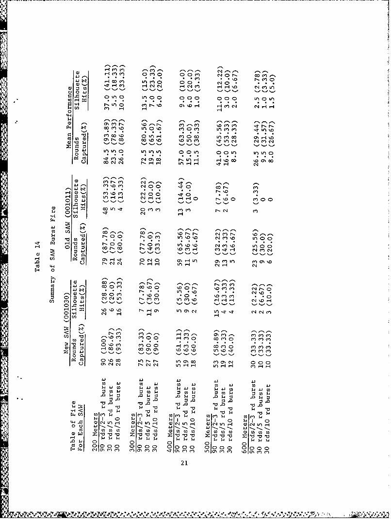
At this point in the SAW test firing schedule, a second SAW was receivedat the USAIS during a visit by materiel and engineering specialists from the
*Armament Division of the U.S. Army Research and Development Command. Thereported advantage of this weapon was that it was newer and that its cyclicrate of fire was closer to specifications than the single weapon used fortesting until this time. It therefore should have been easier to control andit should also have been more accurate. Comparison firing of the two weaponswas conducted at ranges of 200 meters through 600 meters to determine theaccuracy of these assumptions. Test firers during this additional exerciseincluded two world class service riflemen, with machinegun experience,from the Army Marksmanship Unit. A third firer in this testing segment wasa researcher who had been a SAW test participant and a trained machinegunner.The firing scenario required test firers to fire 30 rounds from each of thetwo weapons at each range using the 2-3 round burst method for optimum accuracy.After each burst, the firers would re-lay on target, re-acquire their sightpictures, and fire another 2-3 round burst. This process was repeated untilall 30 rounds were expended each time. Next, the size of the burst wasincreased to 5 rounds and each firer again fired 10 rounds at each range (2bursts). Finally, in the third iteration of the test burst fire was increasedto 10 rounds and each firer fired one 10 round burst. All firers reportedthat the lower firing rate of the new weapon allowed better control of theburst length during 2-3 round bursts; however, the accuracy of the new SAWwhen firing a 2-3 round burst did not appear to be significantly better than
the old, comparatively loose and more extensively fired SAW (Table 14).Accuracy of the newer SAW appeared to be marginally better, however, whenburst sizes were increased to 5 and then to 10 rounds (Table 14).
20
N-%4 * *.-0 t
HC4C' 0c) C9 o 00c~ '4f- ON~
41 r-I.A) 00. cJ0 *nC)0 0C C C
ci 0 4.1r4 'a L 0 0 000 000 IALffI
c4, 9- a,4 H 1 4C 4 C0
4-4
m ~ r"~) %0 e, r. ce) C) 'jo M ca,-* 0 CY) 100V) C 0CY) L l C)L)%
c4 ; f i c;~c t0' c4 0
0 a V) 0 Ln ) 0 00U VO)r uLr(n0
ece)c r-.r" M C14c
00
H A - t o H H
14 H C'4 H- c
to C00 '-N oo-., 00 - xor.r coc'r-.Ia a -0 rOo f0 C) V)% C14 c'n %D W 00H to 0 C *- C* *n *4 *4 *; *
-~~ ~ H'01 fl.00 m-~ 'cx j0:34 1r-4 m-i-" 'TO~~ H C4 M0 -5-- 5 -05, "- 5- .S -, %.'-, 1-0 5-' %-
H- W/ co c 0 14 0 a. Hi f'aal)L cn (7% %.0 u c 1 -H H
H0
p 0~s C) 00O \DNr C'JI-M.0eco 4j 0 ~ 0 c) 00I' 00 M M C-4' * 0
C) 0 4.4 .- 8. c4 '..-., "- 8 .- -'5- - 5
OH C'4 - H0C/
Q)Pq00 C7% 00a ( ON "rCl COCIO)
0.co 0uD'0 ) r, r' tr) a% 0 Clcea% 0001%CN Csi r C14 C14 tn )-4H -1 AH lH IHHr r
4.1 4.1 4.1 4-1 4.1to 4 .1 o 4 .1 to $ 4 .1 to 4 .1 p to 4.I-4.to 14.to W -4-t $-4 5-tow
Q0 a 10, .0~*w- w~ 11-a at w- 10 s-4 V,
P 1l 0 w-a 1 ' $a1 0 w1- 0 w-'1 0a)ar 0'L rf () qL 0C'J ),- Ocq u') - (~u 4 n HI Q OC,4 )ca 41)toto to W to foto a)oot U) tototo Otot to
0 0 a~a~ 10-a- 0-Ia- s-.s- 0 5ooal-as-a) o 0
7K Ca LU
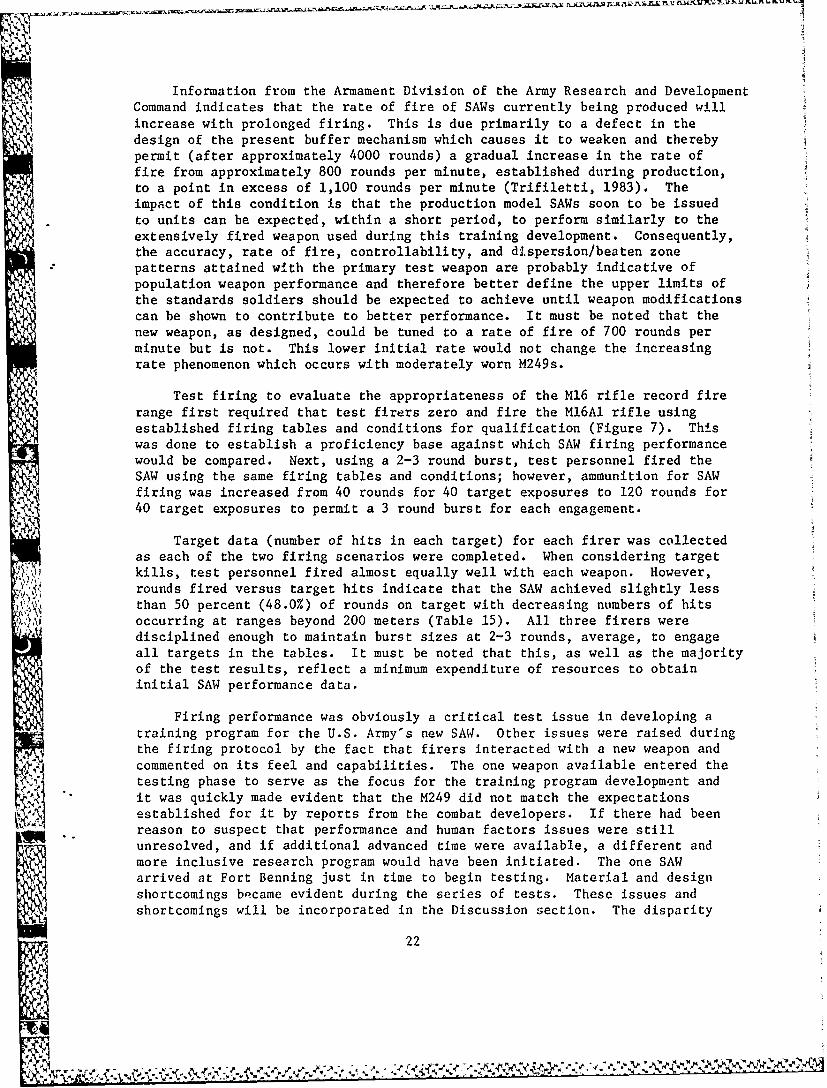
Information from the Armament Division of the Army Research and DevelopmentCommand indicates that the rate of fire of SAWs currently being produced willincrease with prolonged firing. This is due primarily to a defect in thedesign of the present buffer mechanism which causes it to weaken and therebypermit (after approximately 4000 rounds) a gradual increase in the rate offire from approximately 800 rounds per minute, established during production,to a point in excess of 1,100 rounds per minute (Trifiletti, 1983). Theimpact of this condition is that the production model SAWs soon to be issuedto units can be expected, within a short period, to perform similarly to theextensively fired weapon used during this training development. Consequently,the accuracy, rate of fire, controllability, and dispersion/beaten zonepatterns attained with the primary test weapon are probably indicative ofpopulation weapon performance and therefore better define the upper limits ofthe standards soldiers should be expected to achieve until weapon modificationscan be shown to contribute to better performance. It must be noted that thenew weapon, as designed, could be tuned to a rate of fire of 700 rounds perminute but is not. This lower initial rate would not change the increasingrate phenomenon which occurs with moderately worn M249s.
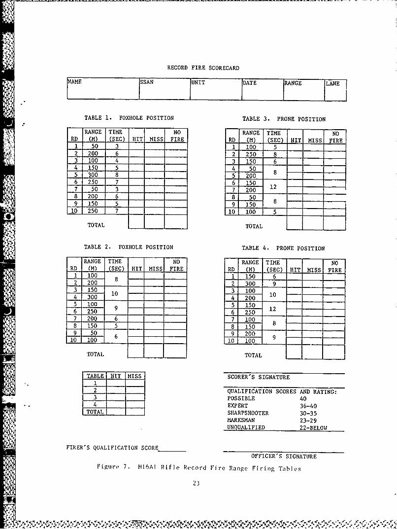
Test firing to evaluate the appropriateness of the M16 rifle record firerange first required that test firers zero and fire the M16AI rifle usingestablished firing tables and conditions for qualification (Figure 7). Thiswas done to establish a proficiency base against which SAW firing performancewould be compared. Next, using a 2-3 round burst, test personnel fired the
SAW using the same firing tables and conditions; however, ammunition for SAWfiring was increased from 40 rounds for 40 target exposures to 120 rounds for40 target exposures to permit a 3 round burst for each engagement.
Target data (number of hits in each target) for each firer was collectedas each of the two firing scenarios were completed. When considering targetkills, test personnel fired almost equally well with each weapon. However,rounds fired versus target hits indicate that the SAW achieved slightly lessthan 50 percent (48.0%) of rounds on target with decreasing numbers of hits
occurring at ranges beyond 200 meters (Table 15). All three firers weredisciplined enough to maintain burst sizes at 2-3 rounds, average, to engageall targets in the tables. It must be noted that this, as well as the majorityof the test results, reflect a minimum expenditure of resources to obtaininitial SAW performance data.
Firing performance was obviously a critical test issue in developing atraining program for the U.S. Army's new SAW. Other issues were raised duringthe firing protocol by the fact that firers interacted with a new weapon andcommented on its feel and capabilities. The one weapon available entered thetesting phase to serve as the focus for the training program development andit was quickly made evident that the M249 did not match the expectationsestablished for it by reports from the combat developers. If there had beenreason to suspect that performance and human factors issues were still
unresolved, and if additional advanced time were available, a different andmore inclusive research program would have been initiated. The one SAW
arrived at Fort Benning just in time to begin testing. Material and designshortcomings became evident during the series of tests. These issues andshortcomings will be incorporated in the Discussion section. The disparity
22
RECORD FIRE SCORECARD
NM SSAN UNIT DATE RANGE LANE
TABLE 1. FOXHOLE POSITION TABLE 3. PRONE POSITION
RANGE TIME NO RANGE TIME NORD (M) (SEC) HIT MISS FIRE RD (M) -(SEC) HIT MISS FIRE1 50 3 1 100 52 200 6 2 250 83 100 4 3 150 64 150 5 4 505 300 8 5 200 8
6 250 7 6 1507 50 3 7 200 12 -
8 200 6 8 509 150 5 9 150 8
10 250 7 10 100 5
TOTAL TOTAL
TABLE 2. FOXHOLE POSITION TABLE 4. PRONE POSITION
JRANGE TIME NO RANGE TIME NORD (M) (SEC) HIT MISS FIRE RD (M) (SEC) HIT MISS FIRES1 00 8 1 150 62 200 8 2 300 93 150 3 1004 300 i0 1 4 200 105 100 9 5 1506 250 9 6 250 127 200 6 7 1008 150 5 8 150 8
9 50 6_9 20010 100
0 i00
TOTAL TOTAL
TABLE HIT MISS SCORER'S SIGNATURE
2 QUALIFICATION SCORES AND RATING:3 POSSIBLE 404 EXPERT 36-40
TOTAL, SHARPSHOOTER 30-35MARKSMAN 23-29
UNQUALIFIED 22-BELOW
FIRER'S QUALIFICATION SCOREOFFICER'S SIGNATURE
Figure 7. NI6AI Rifle Record Fire Range Firing Tables
23
between the anticipated and the actual capabilities of the SAW caused a moreintensive inquiry into past developmental test results. The findings fromthese inquiries open the report Discussion section.
_11
24?V
0~ r- ko C14 boH -V) V
H 1 N m0 Ne p C i NcH
E-4 4J E-40
CY) p
*r-I 0 0ol
Ln LnH
UP to) C 4CCto
H L)oH 0 4 'n co44 co .0l 0C o 4Js 0H 0--1-
4 0 1 "- 0 1 H H
00 -H 41H 0 -r
H4 04 1 CO 04I ~0 0~~HH Q) N4 C141 -? 4
LA a% w. .- ~ ~ -
0) 0* 0 0
0! 001 IA 'A LA %0- LA!
C)) co54~~7 H C i )-JLj C)
C))- 0
25 c
DISCUSSION
Historical
An examination of historical test data which addressed development,
comparative evaluations of the candidate weapons, and eventual acceptance of
the M249 had been made earlier. Access to the results of the Operational Test
(OT-lA, 1979) which had been conducted by the U.S. Army Infantry Board, at
Fort Benning, Georgia, December 1979, had been difficult to obtain. Incontrast, developmental test data had been readily available (Niewenhous,1982). The OTIA (1979) used test soldiers selected from a tenant unit as
- being representative of typical users. The test soldiers fired scenarios
which matched four candidate SAWs with the Ml6A1 rifle (automatic mode), usedto provide comparative baseline performance for the OTlA. Criteria for OTIA
came from a draft version of the Joint Services Operational Requirement (JSOR)which initiated the SAW development and acquisition process. Unclassified
versions of a test criteria for individual live fire exercises required the
successful SAW candidate to:
(1) Provide a 30 percent probability of hitting a standing man-sized
target (identified as a point target) at least once at ranges up to 600 meterswithin 4 seconds from the prone, bipod supported firing position.
(2) Engage four standing man-sized targets (area target) appearingsimultaneously (spaced 10 meters apart to either flank of the base target), at
ranges up to 600 meters within 22 seconds with a 30 percent probability of atleast one hit in each of the four targets from the prone, bipod supported
firing position.
(3) Provide a 30 percent probability of hitting each of three targets
appearing simultaneously, at least once, (consisting of E type targets spaced20 meters apart) at ranges up to 100 meters within 9 seconds from the standing,shoulder supported firing position.
In addition, all candidate systems were to be test fired at the following
range bands:
(1) 0 - 150 meters
(2) 150 - 300 meters(3) 300 - 450 meters(4) 450 - 600 meters(5) 600 - 800 meters
(6) 800 - 1000 meters
In an independent evaluation of Operational Test 1A (March 1980), the
U.S. Army Operational Test and Evaluation Agency (OTEA) determined that none
of the three performance criteria were met by any of the candidate systems or
by the baseline M16. However, performance data did reveal that the M16 (AR)Nperformed significantly better in all test categories than any of the other
systems. A breakdown of performance data by range band clearly indicated that
the probability of hit was high (45% to 65%) only at the lowest range band 0 -
26
150 meters. Beyond that point, hit probability quickly dropped to 20 percentand below. Test firing from the present research effort supports this finding(Table 14).
OTEA also conducted analyses which considered data from various targetranges, the firing positions used, and the types of targets engaged (point
stationary, point moving, etc.). The scenario included three firing positions(prone, standing, and foxhole), point stationary and point moving targets, thethree range bands from 0 to 450 meters, with the baseline M16AI and all fourcompeting weapons. Significant variable interactions were found to include:position with target, position with range, and target with range. Resultsindicated significant differences among weapons, ranges, and firing positions.Under this scenario the M16AI (AR) was the most effective weapon, prone firingwas shown to be the most effective firing position (while standing was clearly
the worst), and it was much easier to fire at targets located between 0 and150 meters than beyond that range. A longer range scenario with targetsbetween 800 and 1000 meters resulted in hit performance that was essentiallyrandom, and that no variable--weapon, position, range, or target--proved tohave significant influence on the final results. A direct comparison ofcompeting weapons to one another, according to OTEA, revealed that whenoverall relative performance was considered, the baseline M16 (AR) was clearlythe dominate weapon.
Test personnel were trained/directed to fire in bursts of 5 to 6 roundseach. However, the burst size used was typically half the desired 6 roundsacross all weapons as was found to be beneficial with the present testing aswell. Examination of hit probability as a function of burst size indicatedrelatively little fluctuation. Hit probability of all rounds of a burst as afunction of burst size was not reported by OTEA. The highest hit probabilityachieved was with the M16AI (AR), with a burst size of 2 (38.8%). Across allweapons, hit probabilities averaged 28.1 percent with a burst of 2 rounds and24.3 percent with a burst of 3 rounds. For larger burst sizes, hit prob-abilities were reported as being lower. These performance findings have beensupported by the present research effort (Table 14).
The exact test results remain classified, however, a final conclusion ofOTEA's independent report suggested that no candidate system appeared to offera significant operational advantage over the baseline Ml6Al (AR). OTEAsuggested that the established target hit performance criteria may have been
Atoo ambitious, and that the criteria should have been reviewed for possiblechange.
In January 1982, a Department of the Army approved JSOR was published.
The performance criteria in this document differed from those in the draftJSOR. Exact criteria are classified, however, in general they were lessdemanding than those used for OTIA. One unclassified requirement was that theSAW should perform better than the M16Al (AR) at 600 meters. It should benoted that this range has been clearly considered beyond the capability of theMl6AI. Another requirement involved hit probability related to of an areatarget at 600 meters, and the last, hit probability for targets at 100 meters.Evaluation of the new criteria involved test personnel from the U.S. MarineCorps and was reported in Addendum I to the Final Report of Developmental Test
27
1W4"P
II (DT-II) of the XM249EI Squad Automatic Weapon, conducted by TECOM (Niewenhous,1982). In this report, approved JSOR criteria were claimed to have been metand that the SAW performed better than the M16Al (AR). However, when the datawere examined in terms of the draft JSOR criteria applied in OTIA and the lessdemanding criteria of DT-II, demonstrated weapon performances were not foundto be significantly different.
The test report data summarized above were not readily available to ARIresearchers until much of the experimentation and test firing of the researchprotocol had been completed. Interestingly, however, is the similarity ofresults and the fact that conclusions reached during the present testing fortraining program development tended to parallel those of both the originaloperational test results as well as those of the independent evaluation ofthat test by OTEA. In addition, conclusions reached by the Army MarksmanshipUnit during its evaluation of SAW weapon physical characteristics and marks-manship capabilities provided further support for some of the previous findings(see Appendix C).
In designing an automatic rifle marksmanship training program for theSAW, an understanding of both the positive and negative operational charac-teristics of the SAW system was essential. The most systematic and compre-hensive equipment research effort conducted to date focused on SAW developmentalaspects (Niewenhous, 1982). In addition, less formal equipment analyses havebeen conducted during the present test firing program in three specificqualities t'- determine appropriate expectations for the SAW when placed in atroop unit tor typical training and employment. These qualities are:reliability, accuracy, and design characteristics. These elements are criticalto program development in that trainers must be made aware of the performancecharacteristics of the weapon they are training.
Weapon Considerations
Reliability
During all phases of test firing and training development, observationsof weapon breakage and/or malfunctions were recorded. With the exception oftwo weapon failures relatively earlier in the test program, the SAW's firingreliability while using belted ammunition was extremely good. Several malfunc-tions occurred while firing ammunition from standard M16 magazines; however,these were determined to be magazine-related problems rather than weaponproblems. Similar problems have been recorded as part of ARI-Benning researchBwith the M16 rifle (Evans & Osborne, 1983).
After approximately 600 rounds had been fired through the weapon, theejection port dust cover separated from the weapon, allowing the spring andretaining bar to drop into the receiver, causing the weapon to fail. After a
few minutes to discover the source of the problem and to subsequently removethe loose parts from the weapon, the weapon again functioned with no apparentloss in efficiency.
28
After firing approximately 1,300 rounds in the test program, the cockinghandle exited the forward opening of the slide track on the right side of thereceiver and separated from the weapon. The retaining pin at the forward endof the cocking handle slide track had sheared at a point of 1/3 of its length,allowing the cocking handle to separate. The handle and the remaining portionof the pin were reassembled and firing continued, but after approximately 50additional rounds the cocking handle began to bind in the slide track andsevere friction was encountered at the forward position. Firing was discon-
* tinued and inspections revealed that the retaining pin dislodged during firingand a metal burr had been forged on the cocking handle by uneven pressuredistribution from impact against the damaged pin. Proper repair was accom-plished locally.
With the exception of the two minor weapon parts failures and the mal-functions while using magazines, approximately 7,000 rounds of belt-fedammunition were fired under normal range conditions without a single jam ormalfunction.
Accuracy Variables
Quick change barrel. The SAW is equipped with a quick changebarrel. When locked into position, a small amount of movement around the rota-tional axis was found. When the SAW is held in a steady position, this barrelmovement has the potential of moving the strike of a round as much as 1/2 to3/4 inches when firing at a 10-meter target. Changing barrels indicated thatthe looseness on this weapon is in the chamber recepticle of the receiver and
not in the barrel. It is not clear whether the test SAWs available aretypical and were manufactured with faulty chambers, or that the loosenessfound is a result of fair wear and tear on the alloy receiver. Only oneweapon was available for the majority of testing. A second weapon examineddid not exhibit as much looseness. Some barrel/receiver movement, controlledby the direction of pressure on the bipod legs (pull rearward/push forward),contributed to the vertical displacement of shot groups during testing.
Rear sight on cover. The rear sight is mounted on the feed traycover which has some noticeable horizontal and vertical play caused by its useof spring tension to retain it in place. Each time the rear cover is closed,the rear sights may be in a different position, causing significant horizontaland vertical changes in the placement of bullets.
Rear sight windage adjustment. The rear sight has about 4 1/2clicks of uncontrolled movement which is equivalent to a 4-1/2 mil angle.it can be pushed to the left or right or it may move easily to either left orright during firing as a result of the action of the weapon. When normalwindage adjustments were made from either the extreme right or left, the sight
typically did not move any noticeable amount for the first two clicks, itmoved a small amount on the third click, and made a complete move only on thefourth and subsequent clicks. This detracts considerably from the accuracy ofthe zeroing process and the subsequent consistent placement of bullets.Replacement of the windage adjustment screw with one milled by U.S. ArmyMarksmanship Unit gunsmiths was successful in substantially reducing theexcess lateral movement of the sight.
29
{i Rear sight (peep) aperture. Doctrine calls for the SAW to be
employed as a one-man automatic rifle, so the gunner must be able to observeand subsequently adjust his own fire. However, the very small peep apertureon the SAW (2mm) provides a very limited field of view. During the firingsequence of the SAW, gun vibration and flash from the muzzle completelyobscured the gunners' view of the target and their opportunity for theobservation of impacting rounds was minimal. A larger aperture would allowbetter viewing of the target area, and more importantly, better observationof impacting rounds. In the opinion of the test firers, the trade-off ofobservation versus sight alignment precision favors a large rear peep sight onan automatic weapon such as the SAW. Earlier comparison firings between thelightweight M60 machinegun and the standard M60, conducted by two experiencedshooters who were SAW firers in the present test, indicated that the largerpeep sight on the lightweight M60 was more usable in terms of target viewingand observation of impacting rounds. Initial indications are that a larger
aperture on the SAW would enhance both training and combat effectiveness.
Design Characteristics
Bipod. The bipod has been designed to help prevent horizontalmovement; however, because the flat spade of the feet are on the sides asopposed to front or rear, the SAW freely moves on a line with the target whensupported by firm or frozen ground. In addition, extending the bipods toraise the front of the weapon appeared to contribute to degradation in firingaccuracy during some tests. Stability of the firing platform appears to be
reduced.
Butt stock and folding shoulder rest. The butt stock and folding
shoulder rest are slick surfaced and very difficult for the firer to holdsecurely into the shoulder. The addition of a rough material on the surfaceof the butt stock appeared to improve firing performance according to firers.
4 The folding shoulder rest on the SAW is a heavy wire spring device whicheasily moved past its upper limit when relatively moderate downward pressurewas applied. This caused the weapon to slip from the firer's shoulder andwhile firing, go out of control placing the burst fired well over the top ofthe target. During test firing, this problem was overcome by the constructionof a 1/4" soft metal band (by USAMU) which when positioned on the shoulderrest near its mounting point prevented the wire spring from spreading andmoving beyond its upper limit.
The design of the weapon does not permit the firer to establish a good
stockweld and comfortable holding position. The stock appears generally to betoo short for adequate holding. The addition of a pad to the butt plateimproved the firer's ability to hold the weapon. Finally, the short distancefrom the comb of the stock to the rear sight aperture makes it impossible tosee through the sights at all the lower range settings while wearing the M17protective mask.
o7 Cyclic rate of fire. The SAW is designed to fire at a cyclic rate
of 725 rounds per minute (normal setting) and 1,000 rounds per minute (maximumsetting) with the latter being employed only when the weapon will not function
30
-W, --A.
properly in the normal position. It must be noted that the weapons are beingtuned to fire at a rate of 800 rounds per minute or more at the normal gassetting. Rounds fired at the maximum setting on an otherwise properly func-tioning weapon tend to impact with wider dispersion and in more erraticpatterns. Information from the Research and Development Command indicatesthat continued firing of the SAW in the normal mode (approximately 4,000rounds) will result in the gradual increase of the cyclic rate to a point inexcess of 1,100 rounds/minute. This is apparently due to a weakening of thebuffer mechanism. A buffer block or new assembly that will maintain thenormal low cyclic rate of fire appears critical to achieving the most con-trolled, and therefore effective, SAW performance for employment.
Ammunition. The SAW gunner should be able to depend on tracer
observation to adjust much of his fire. However, the M856 tracer round, as itpresently exists, ignites much later (140m) and burns with less brilliancethan does the M196 round. The M856 tracer is particularly difficult to see atassault ranges (out to 150m), making the tracer almost useless at close range.From the gunner's position behind this gun, it has been reported that it isalso extremely difficult to observe tracers at any range. The trajectory andmuzzle flash of the weapon, coupled with the weak illumination of the trace,make the tracer an ineffective round. A more brilliant trace will not overcomethe total scope of the problem for long-range target engagement; however, atrace which is bright and begins burning early would contribute to the gunner'sability to observe and adjust fire on close targets as well as enhance theassault fire capabilities of the weapon.
Range Considerations
Another major consideration during SAW testing and training developmentwas training range needs. It was critical, where possible, to take advantageof range facilities currently available at the various US Army installationsthat could support SAW training with few modifications. The final phase ofthe SAW Test fire plan was directed specifically at evaluating this aspect ofthe SAW training resource requirements and the relevant impact on programdevelopment and implementation along with SAW fielding. The SAW, like otherindividual weapons, can be trained initially at short distance firing ranges(10 meter, 25 meter, etc.) in order to provide closely controlled immediateshot grouping and zeroing feedback to the firer. Since the SAW's point of aimand point of impact match ballistically at 10 meters when a 500 meter sightsetting is used, and since this range configuration is frequently found onArmy installations, a need does not exist to develop a new short dista,-erange. However, the SAW in the role of an automatic rifle could benefit froma specific target configuration to support its unique role in the squad.Training at this range on a SAW specific target could better prepare thegunner to engage point and area targets as well as teach distribution of
suppressive fire. Until the SAW 10 meter targets can be developed andpublished, the standard M60 machinegun 10-meter target is certainly suitablefor all interim 10-meter training.
Transition range firing includes a series of live fire exercises whichrequires the gunner to apply all the fundamentals of marksmanship learned in
preparatory marksmanship training and 10-meter range firing. It is on the31
o IC
transition range that the SAW gunner demonstrates his proficiency in automaticweapon marksmanship by engaging the types of targets he would be expected toengage in combat. Evaluation of several possible SAW transition rangesrevealed that given ranges with appropriate limits and safety fans, most rifleand automatic weapon ranges currently available could be used or modified foruse by the SAW.
The M16 Rifle Record Fire Qualification range appears to be appropriatefor interim adaptation to SAW use. Test firers were able to exercise sufficientburst control to distribute the 120 rounds available during engagements toall 40 targets in the rifle qualification coure (see Table 15). Hit per-formances from these expert shooters were comparable to those obtained usingthe standard MI6Al rifle. It should be noted that all three firers had becomequite familiar with the SAW by this point in the testing and may have performedbetter than the typical user. The Ml6Al used was only zeroed and fired forqualification by each, not fired enough to provide peak performance thougheach was an expert shot. Given these caveats, and the limited number offirers available in the test, these performances may represent better thanaverage firing when compared to typical users.
Test firing on the M60 machinegun transition range required test firersto engage targets (single "E" silhouette) at ranges from 400 meters to 800meters. Test personnel fired approximately 600 rounds while varying the burstsize from 2-3 rounds to 20 rounds. Targets were killable single "E" silhouettesremotely controlled from the firing line. Target hits were achieved only atthe 400 meter and 500 meter ranges. Safety regulations prevented the collectionof actual hit/miss data typically accomplished by counting hits in the targetarea. Test personnel reported they could not observe their rounds at thegreater ranges and, consequently, were unable to adjust their fire. Anattempt to adjust rounds on target by an observer using binoculars was notsufficient to overcome the low brilliance and wide dispersion patterns oftracer rounds. In general, test personnel felt that this range demonstratedpotential for SAW training using its closer range targets; however, targets at
closer ranges (100, 200, and 300 meters) would be required to enhance suit-ability. The performance data obtained during this subtest, however, wasinsufficient to develop positive recommendations.
Current Interim Training Development
Implementation
The SAW individual and collective training plan currently approved by theSAW proponent, the USAIS, proposes institutioial fai. iarization training forinfantrymen with qualification training and record fire being conducted in theunit (United States Army Infantry School, 1983). Other personnel are expected
to receive only familiarization training in order to have the ability to placethe SAW into operaticn and then to apply basic marksmanship skills with verylittle practice. An approved USAIS SAW training task list is presented inTable 16.
32
jg~2~r.%
Table 16
SAW Training Tasks
Status of standards
Training task and conditions Training environment
Perform operator mainten- Established and use Institution/unitance on SAW and ammunition will validate
Load, reduce stoppage, Established and use Institution/unitand clear SAW will validate
Prepare a range card* Identical to M60 Unit, if at all
machinegun appropriate
Zero the SAW at 10 meters To be established Institution/unit
Qualify with the SAW To be established Unit
Field zero the SAW Research will validate Institution/unitproposed standards
Zero the AN/PVS-4 to the To be established UnitSAW at 25 meters
Place into operation the To be established Institution/unit
AN/PVS-4 and SAW
Mount/dismount an Established, but Institution/unitAN/PVS-4 to the SAW included in other tasks
Lay the SAW using field Established and Institution/unitexpedients complete
Fire the SAW for Established and use Institution/unitfamiliarization will validate
Perform assault fire To be established Institution/unittechniques
Fire the SAW while wearing To be established Unitprotective gear
*Since the SAW is not expected to be employed in the tripod mode, preparation
of a sector sketch should be taught in lieu of preparation of a range card.
33
.,.{
Training Issues
Many of the tasks in Table 16 require extensive firing tests to establishand validate appropriate training conditions and performance standards for theinitial entry soldier. Delays in the receipt of production weapons preventedthis phase of training development to begin until the ist Quarter FY84 (November,1983). In addition, only limited quantities of ammunition (SS109/LllO not
production M855/M856) were available at the same time. Finally, acceleration.- of the development effort to provide training materials that would accommodate
3rd Quarter FY84 fielding of the SAW required the development of a program ofinstruction for immediate implementation using minimum resources and existingranges.
Zeroing
Past research has shown that the development of an appropriate zeroingprocedure for the SAW would be a primary topic of the present research(Smith, Thompson, Evans, Osborne, Maxey, & Morey, 1980). Based upon trajectorydata, a battlesight zero distance is established which maximizes hit probabilityfor high priority targets throughout the expected range of employment. Inorder to maximize hit probability, the zero trajectory closely follows theweapon's line of sight for the greatest possible distance. This is criticalin establishing a range limit for grazing fire with machineguns as well. Oncea battlesight zero distance and its associated trajectory curve have been
selected, a procedure is developed to obtain an approximate zero at a reducedrange to save training range time and enhance immediate feedback (e.g., 10 or25 meters).
In the case of the SAW, however, the problem with and objective of,establishing a weapon zero was somewhat different. Because the sightingsystem is incremented for range, the need to establish a "battlesight zero" is
subordinate to zeroing the weapon for point of aim/point of impact. Once thefirer is assured that rounds will impact on point of aim, theoretically, theweapon is zeroed for any range increment on the sight. Test firing from arigid bench rest at a 10 meter target indicated that rounds would impact at
the point of aim with a 600 meter sight setting on the weapon. This, however,did not hold true during firing by personnel at the same 10 meter range. Itwas determined that a 500 meter sight setting provided a more accurate point
of aim/point of impact for zeroing.
After determining the proper range setting for 10 meter zeroing, the
next question concerned procedure. The SAW is to be employed using burstfire, however, attempts made to zero the SAW with various burst sizes producedgroups that were too large and erratically dispersed to determine appropriatecenters and to make subsequent corrections.
The chief problems encountered were determining the sequence of impactingrounds and maintaining a tight shot group to measure. Single shot fire atthis range, therefore, proved to be a more effective zeroing method. Once theweapon had been properly zeroed using single shot fire, creating a beaten zone
34
Je
on and around the point of aim was then more easily achieved. Single shotfire also permitted development of measurably tight groups which eased thezeroing process as well.
Determination of a "battlesight zero" or, more accurately, a rangesetting that would maximize hit probability throughout the expected range ofemployment required analysis of trajectory and maximum ordinate data. Sincetrajectory information for all ranges and ammunition has not been completed bythe appropriate ballistics laboratory, the most accurate data available isthat which is depicted in Figures 8 and 9. Infantry doctrine states that aneffective battlesight setting for automatic fire is one that will provide fire
that is approximately parallel to the ground so that the maximum ordinate doesnot exceed one meter of elevation above the ground anywhere along the trajectoryflight path (FM 101-5-1, p. 1-56). This is grazing fire and an examination ofFigure 8 reveals that a 500 meter sight setting is the maximum range thatsatisfies this criteria.
Accuracy
Ammunition
To date, MI6Al rifle marksmanship training has focused onengaging targets at 300 meters and less. One purpose in acquiring the SAW wasto extend both the range and volume of accurate fire that can be delivered by
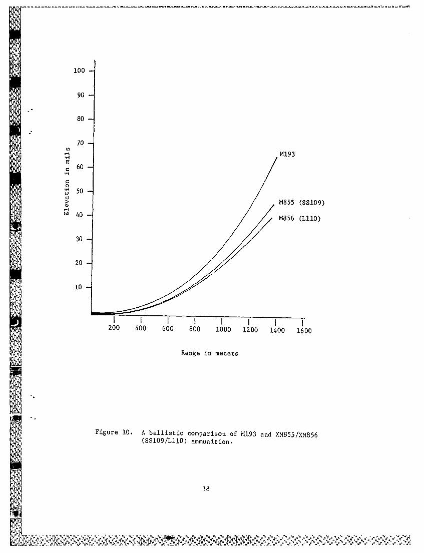
'squads in combat. However, the ammunition to be used in the SAW (M855/M856)may not be available in useful quantities in the near term. Ballistic datahave indicated that the use of M193 ball ammunition will not substantiallyalter SAW firing performance out to ranges of 600 meters (Niewenhous, 1982).Figure 10 illustrates that the theoretical ballistic difference between M193and SS109/Ll1O ammunition (which should meet production M855/M856 standards)does not exceed one milliradian of elevation difference until rounds reach 600meters, and if the maximum practical range for the squad automatic weapon and
targets is extended, this comparability of ammunition has been expected topermit consistent training procedures to 600 meters.
The current test firing of limited quantities of M193 ammunition producedcomparable performance to SS109 ammunition only out to the 300 meter range.Beyond 300 meters, M193 round performance became so erratic and widely dispersed
in burst fire that it was impossible to capture all the groups on a 6" x 6"target panel. Subsequent discussions with Ammunition Branch, U.S. ArmyResearch and Development Command (Trifiletti, 1983) indicated that performancetests have shown that variances in ballistics and projectile stability havecaused the M193 round to begin "floating" after 200 meters of flight. This"floating" action alters the trajectory of the round in such a manner that theaccuracy of fire beyond 200 meters is unpredictable and extremely difficult toachieve. Also noted during M193/SS109 test firing is the different zerorequired for each of the two rounds. The initial variances noticed during 10meter firing was thought to be caused by shooter instability, however, longerrange firing using the same zero for each round produced otherwise unexplaineddivergence between shot group locations. Field zeroing at range (100 - 300meters) and refiring at 10 meters confirmed that the M193 ammunition consistentlyrequired a sight setting difference of one and one-half milliradians of rightlateral (windage) adjustment when compared with SS109/M855 ammunition.
35
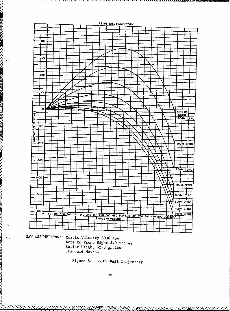
SS109 BALL TRAJECTORY
-000300R
800M0ER
70010ER
*
--AWASUPTON: Muzl-elciy306-p
500M Z00
RANG IN OFER
SIGH
3D36
- 40
400M ZERO
.. SAW ASSUMPTIONS: Muzzle Velocity 3036 fps~Bore to Front Sight 2.0 inches~Bullet Weight 62.0 grains~Standard Metro.
~Figure 8. SS109 Ball Trajectory
!3
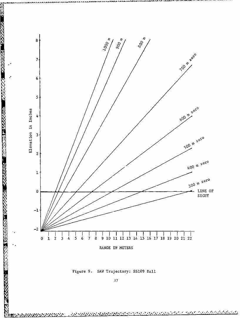
o o 0
7 -4
V 65-
0
-
o 3
10
o-4
0 LINE OFSIGHT
-2SI I I I I I I I I I I I I I I I I I I I I I
0 1 2 3 4 5 6 7 8 9 10 11 12 13 14 15 16 17 18 19 20 21 22
RANGE IN METERS
Figure 9. SAW Trajectory: SS109 Ball
37
I!!__II
100
90
80
70H M193
= 60-o
0" 50-> M855 (SS109)
40 - ,M856 (LilO)
30-
20-
10-
I I I I I I I I200 400 600 800 1000 1200 1400 1600
Range in meters
Figure 10. A ballistic comparison of M193 and XM855/XM856(SS109/L1IO) ammunition.
38
+V'+
Burst Size
One critical factor which affects SAW employment and was measured in an
extensive small arms suppression study was burst size (Combat Developments
Experimentation Command, 1976). It was found that the actual burst size had
little effect on suppression, but along with proximity to the target intervalsbetween bursts did. Other studies and tests have been conducted to determine
the optimum burst size of both automatic rifles and general purpose machineguns.In a service test conducted by the U.S. Army Infantry Board, optimum burst
sizes differed somewhat between machinegun and automatic rifles (Roberts etal., 1965). Burst sizes in excess of three rounds were relatively ineffective,even with bipod mounts, using automatic rifles (5.56mm to 7.62mm) and carbines.
Further, it was found that the M60 machinegun bursts of six rounds providedoptimum effectiveness. Although there was not a reported significant difference
in hit capability between machinegun bursts of three and six rounds, the
highest combination of hit capability, hit probability, and percentage of
actual hits was obtained with six-round machinegun bursts (Roberts et al.,
1965). Larger bursts, 10 or 15 rounds, did not provide corresponding increases
in target coverage.
Current testing to determine the optimum burst size for SAW employment
involved experimentation with 2 to 3, 5, and 10 round bursts. Figures 11 and
12 illustrate percentages of hits achieved for each range when engaging an
"E" silhouette on a 6" x 6" witness target frame. Clearly, the 2 to 3 roundburst was the most effective in terms of accuracy (rounds captured/silhouette
hits) and hit probability at range. The proximity of the burst to the target
equates to effective suppression as well. The primary problem encountered
during SAW burst fire testing was that the shooter lost control very early in
the burst (could not hold the weapon on target), perhaps after two or three
rounds which does not provide adequate target coverage. For any given firing
scenario, the SAW's high cyclic rate of operation (700 (800)-1100 rds per
minute), vibration, and muzzle blast all contribute to target obscuration orthey at least hinder target observation. Consequently, close targets (out to
ranges of 300 or 400 meters) can be hit by engaging as one would with a rifle,
but the SAW's erratic, widely dispersed fire cannot be controlled for the
extended burst to develop the beaten zone necessary to hit distant targets.
After extended practice and familiarity with the SAW, a gunner is morelikely to increase his skill at engaging greater range targets with possibly
larger size bursts. However, for the novice firer the most effective weapon
familiarization and/or qualification will be achieved using the more observable,
more easily controlled 2 to 3 round burst.
Range Firing
The SAW was developed for the primary purpose of replacing
the two MI6Als carried by the automatic riflemen in the rifle squad. Part
of the rationale in support of the SAW was that threat squads carried a light
machinegun which was effective to ranges of 800 meters. The requirements
document stated that the SAW was to be effective against point and area
targets at 600 meter ranges and area targets at the 800 meter range by
achieving a 30 percent probability of hit on each target. As reported by
39
antecedent test reports (OTIA 1979, Independent Evaluation, OTEA 1980, and
DT-II, 1982) neither the SAW nor any other candidate weapon met the establishedtest criteria. The highest probability of hit (45%) achieved by all weaponsystems was at ranges of 150 meters or less.
Based on the results of previous tests, concern arose regarding theactual maximum effective range of the SAW when employed as an individualweapon. To address this issue, the SAW was test fired using ordinary bipodsupport at ranges from 100 to 900 meters. The results illustrated in Figures11 and 12 reveal that probability of hit was less than 50 percent (41.11%) at200 meters and decreased rather quickly to less than 30 percent at 300 meters.These measures were obtained using two to three round bursts fired by threeexpert marksman while performing side-by-side gun comparisons.
Training Program Development
Based on previous test data, the emerging results of current testing, andthe anticipated further development of ammunition and weapon modifications,the SAW proponent (USAIS, Fort Benning) decided that interim training programsfor familiarization and qualification of Squad Automatic Weapon gunners wouldbe most appropriate to accompany the SAW to the field. This interim guidancewas to take the form of a Field Circular (FC 23-10, March 1984) which wouldassist commanders and their staffs in developing immediately useful unittraining programs. It was anticipated that as modifications and improvementscould be incorporated into the ammunition and weapons, revisions to thetraining programs would be made.
With this guidance, ARI/Litton Mellonics test and research personneldeveloped the field circular 23-10, Basic Marksmanship Training - Bipod-Mounted
Squad Automatic Weapon (March, 1984). Major concepts and considerationsincorporated into the field circular are outlined below:
o The maximum range for SAW familiarization and qualification firingdoes not exceed 400 meters.
o All training is to be accomplished using existing equipment, targets,
and range facilities.
o Ammunition allocations are limited to essential amounts and includeuse of either SS109, or M193 if the new ammunition is not available.
o The prescribed burst size is a 2-3 round burst.
o Initial zeroing is accomplished using single shot fire to develop
groups.
o Assault fire and night fire techniques will be developed and publishedas improved tracer ammunition becomes available.
As published, Field Circular 23-10 introduces the scope, purpose andobjectives of SAW training. This is followed by a discussion of the weapon'scharacteristics to include weapon functioning and ammunition performance.
40
-X ! .A-!- K x
100- 2-3 Rd Burst
5 Rd Burst.... 10 Rd Burst
90.
80-'0.
o 70
*0 60
41 -
~o • \
40-
30-
20.
10-
200 300 400 500 600 700 800 900
RANGE IN METERS
Note: Data presented from Tables 13 and 14.
Figure 11. Burst Fire Performance Rounds Captured on 6' X 6' Panel.
4 3
100- 2-3 Rd Burst5 Rd Burst
...10 Rd Burst
90
-80
80
6 0-44
0
50
30I
00
0)
0050U 0 0 bU /U o 0
~ 40
Next, the SAW's characteristics of fire and preparatory marksmanship trainingare presented. The final section is devoted to detailed explanations of rangefiring to include qualification and familiarization firing. The appendices ofthe circular contain the detailed training programs for both qualification andfamiliarization as guidance to using units. In addition, a dry fire performanceexamination is provided along with proposed ammunition allocations and interimfiring tables. The final appendix item is a composite record score carddepicting firing subtables, target scenarios, and time requirements. Table 17presents the table of contents of the field circular while Figure 13 presentsan overview of the interim training programs.
The circular was delivered to the proponent for the addition of graphics,formatting, and formal staffing in February and March 1984. In April 1984 itwas approved for publication and is currently being reproduced and distributedto units as they receive production weapons.
Constraints in Program Development
The development and implementation efforts described in this report have
been largely pursued with consideration for the limited existing trainingresources in the overall education system of the US Army. In a trainingenvironment with unlimited resources, it is expected that SAW marksmanshipinstruction could be greatly improved. During the process of developing SAWmarksmanship training programs the results of a system wide evaluation oftraining constraints suggest that the potential effectiveness of these programsis limited. In particular, it is believed that the following factors have orwill limit the potential effectiveness of SAW marksmanship training:
1. The SAW was scheduled for fielding in early 1984. Due in part to
the non-availability of test weapons and ammunition, the training materialswhich must precede or at least accompany the fielding of a new weapon systemhad not been developed. The training package (interim) development requiredthe accelerated testing effort and delivery of training programs to be accom-plished in a four (4) month period. This period began with the first actualobservation, by training program researchers and developers of the SAW.
2. The performance results obtained during the majority of this trainingdevelopment were based on the availability of only one M-249 SAW (Number001011). A second weapon (Number 001030), received late in the research
effort, was immediately integrated into the remaining test firing scenarios;however, this small representation of the potential weapon population can onlydetract from the potential validity of the test findings.
3. Efforts to meet early expectations for the weapon and to establishrealistic and obtainable standards at the maximum allowable engagement rangewere prevented by weapon system design deficiencies as well as by poorammunition (tracer) performance. Considerable effort was expended in theattempts to document and overcome the discrepancies between expected andachieved performance which ultimately resulted in training criteria that are
_Nsignificantly less than the weapon's earlier reported capabilities.
43
4 ~.J~*~ y~w~ ~ y.~, ~ ~dC~f.~' ::'r
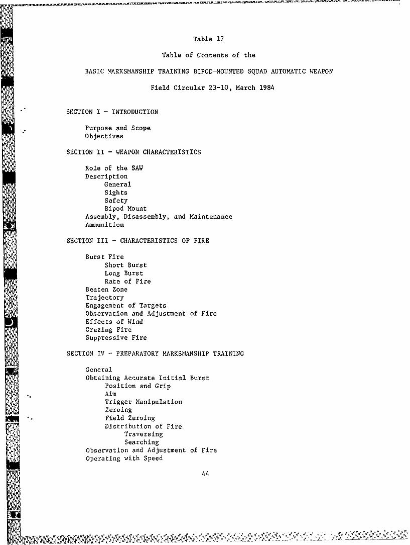
Table 17
Table of Contents of the
BASIC MVXKSMANSHIP TRAINING BIPOD-MOUNTED SQUAD AUTOMATIC WEAPON
Field Circular 23-10, March 1984
SECTION I - INTRODUCTION
Purpose and Scope
Objectives
SECTION II - WEAPON CHARACTERISTICS
Role of the SAWDescription
GeneralSightsSafetyBipod Mount
Assembly, Disassembly, and MaintenanceAmmunition
SECTION III - CHARACTERISTICS OF FIRE
Burst FireShort BurstLong BurstRate of Fire
Beaten ZoneTrajectoryEngagement of TargetsObservation and Adjustment of Fire
Effects of WindGrazing FireSuppressive Fire
SECTION IV - PREPARATORY MARKSMANSHIP TRAINING
GeneralObtaining Accurate Initial Burst
Position and GripAim
Trigger ManipulationZeroingField ZeroingDistribution of Fire
Traversing
SearchingObservation and Adjustment of FireOperating with Speed
44
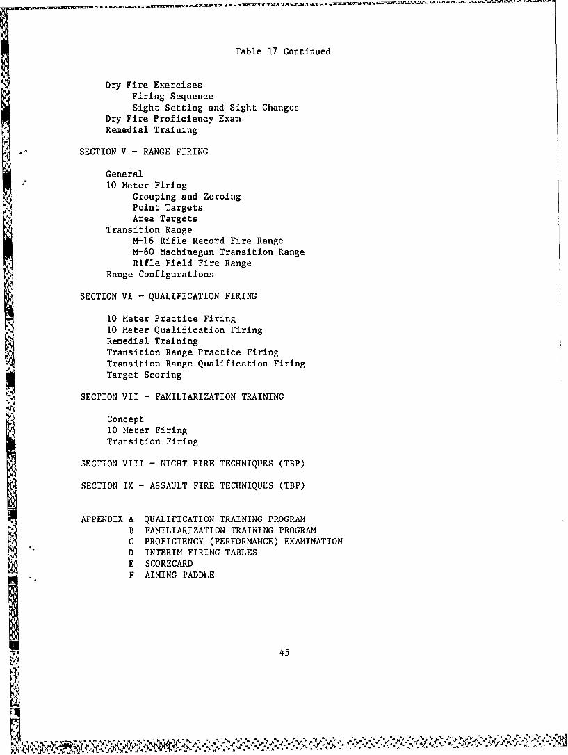
Table 17 Continued
Dry Fire ExercisesFiring SequenceSight Setting and Sight Changes
Dry Fire Proficiency ExamRemedial Training
SECTION V - RANGE FIRING
General10 Meter Firing
Grouping and ZeroingPoint TargetsArea Targets
Transition RangeM-16 Rifle Record Fire RangeM-60 Machinegun Transition RangeRifle Field Fire Range
Range Configurations
SECTION VI - QUALIFICATION FIRING
10 Meter Practice Firing10 Meter Qualification FiringRemedial TrainingTransition Range Practice FiringTransition Range Qualification FiringTarget Scoring
SECTION VII - FAMILIARIZATION TRAINING
Concept10 Meter FiringTransition Firing
3ECTION VIII - NIGHT FIRE TECHNIQUES (TBP)
SECTION IX - ASSAULT FIRE TECHNIQUES (TBP)
APPENDIX A QUALIFICATION TRAINING PROGRAMB FAMILIARIZATION TRAINING PROGRAMC PROFICIENCY (PERFORMANCE) EXAMINATIOND INTERIM FIRING TABLESE SCORECARDF AIMING PADDLE
K 45
* 4.-v
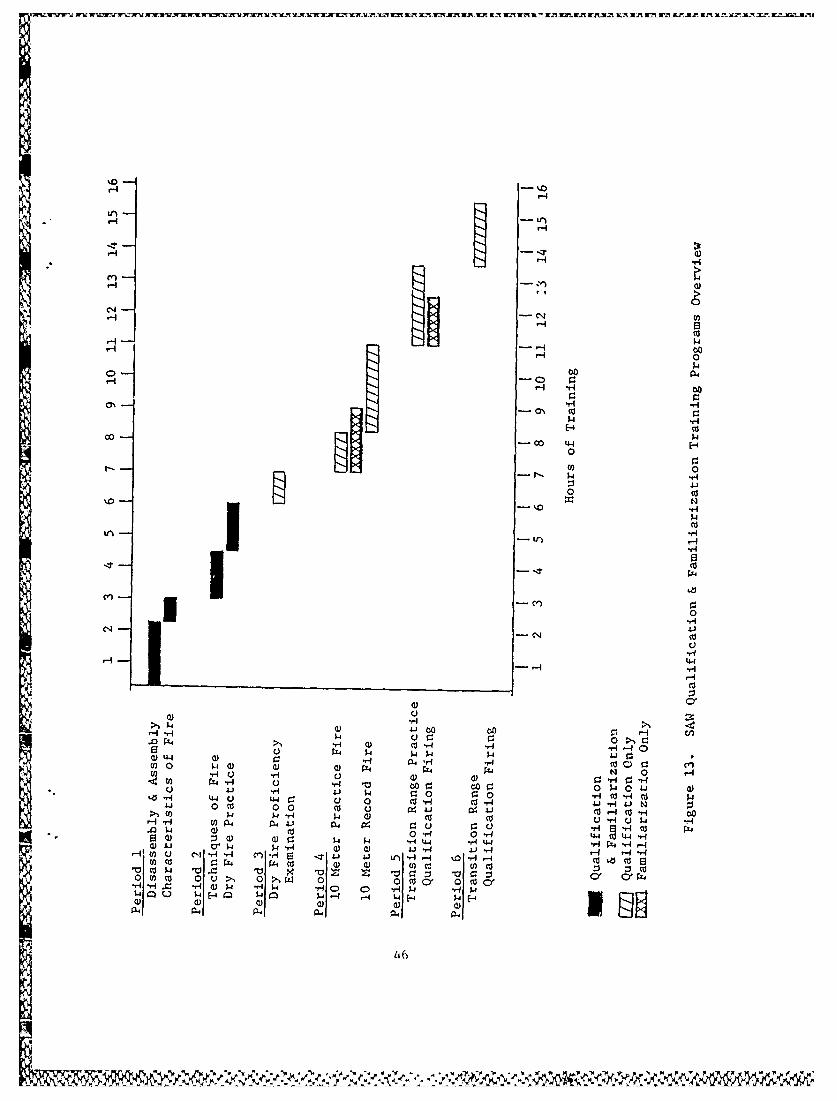
Hn -'
crH
U, 4[N3
Hw
000
Ch~ co
I91F -- w0 -
-
oc~co
0N - 41
-H4
W Ux
r I4H4 0 C:
-H Q) co .14-H 4U44 a44 r4 w2 C 0 H4
;74 H0 H 0 0 0ka -H C: 0 (o H co, c44 4 C: u 0 c -441- i.N0- 0(o 0 0 co2 u 1c
a- -i~4 04 0i ( () r U H w r HIv 0- :4 0 1 4 4El Q z Q 0 w5. U
41. 0.. -1r.-
a)46 -q 41r
-4E T 41 V H q % H -
4. Available resources for training development were limited. Whilea total of approximately 7,000 rounds of ammunition were expended for trainingdevelopment purposes, limited availability of SSI09/Ll0 ammunition preventedfurther testing and evaluation. The ammunition available may not match laterproduction M855/M856 ammunition either. In addition, while it is believedthat the proposed ammunition allocation levels are adequate for initial SAWtraining purposes, they are considered the minimum essential and reductionsbeyond these levels are likely to decrease substantially the effectivenessof SAW marksmanship programs. Nevertheless, the interlm training proceduresdeveloped for the SAW do maximize the learning opportunities obtainablthrough the systematic use of each round.
~1
i
'i
CONCLUSIONS AND RECOMMENDATIONS
Conclusions
The first and most telling general conclusion of this testing and trainingdevelopment program is that the squad automatic weapon, in its present con-figuration, does not perform to its expected capability and, therefore,
• - the average gunner will not be capable of placing accurate volumes of fire on
targets at extended ranges.
The SAW has several design deficiencies which make distant targets(greater than 400 meters) difficult to successfully engage. The SAW isdifficult to control for the extended bursts of fire which are necessary tohit more distant targets. This tends to suggest that the SAW cannot beemployed efficiently and effectively at greater ranges. In fact, however, theSAW can engage targets at greater range, but test firing has shown that theskill to successfully hit targets at long range (500 - 800 meters) withaccurate short bursts or to hit targets at 300 - 400 meters with longer burstswould take considerable practice to develop.
Automatic fire is employed in bursts so as to develop a beaten zonewith an adequate number of rounds to provide target area coverage. The sizeof the burst should logically depend on the nature of the target. However,test firing of the SAW indicates that burst sizes in excess of three rounds(5 and 10 round bursts) were relatively ineffective and did not providecorresponding increases in target coverage. With the SAW the most effectivebeaten zone is created by firing rapid two to three round bursts with shortintervals between bursts for reacquiring and relaying on the target. Theo-retically, this will provide the most effective form of suppressive fire aswell.
The XM856 tracer round in flight and the strike of all the 5.56mm pro-jectiles tested are difficult to sense and almost impossible to observe frombehind the sights. Gunners will have difficulty observing and making subsequentadjustments of fire and will therefore need some assistance when field zeroingto determine adjusted points of aim. Since the SAW is not a crew-servedweapon, this will require support from a team leader or fellow rifleman duringzeroing.
The most consistently effective position for firing the bipod-mounted SAWis the M60 machinegun position published in FM 23-67 (1964). In terms ofstability and the gunner's ability to control the action (movement) of theweapon, the M60 position provides the best body alignment, a steadier grip,and the least dispersion of rounds in a group.
The SAW should be zeroed at a range of 10 meters with a 500 meter rangesetting on the sight. During the conduct of zeroing procedures, the use ofsingle shot fire to develop groups provides the most useful diagnostic feedbackto the new gunner as well as the most accurate and reliable weapon zero.
SAW transition training can be conducted on a rifle record fire range(TRAINFIRE Qualification), a rifle field fire range, or a machinegun transition
48
range. On all ranges, close to moderate distance targets (100 - 400 meters)should be used. Targets at ranges greater than 300 meters should be "doubleE" silhouette or larger.
Both the M855 and M193 ammunition may be used while conducting trainingwith the SAW. An important consideration, however, is not to mix differenttypes of ammunition during live-fire exercises. Variances in ballistics andprojectile stability result in differences in zeroing adjustments and downrange dispersion patterns. In addition, these differences limit the traininguse of M193 ammunition to ranges of 300 meters and less.
Recommendations
In an attempt to overcome training development problems and employmentconstraints described earlier, research in the following four areas is appro-priate: training program validation (both familiarization and qualification),assault fire techniques, night fire, and testing of anticipated productimprovements.
Training Program Validation
The majority of test firing during this training development effort was
conducted by expert military and civilian automatic weapon marksmen and forsome (few) exercises, novice shooters were used briefly. Unfortunately, thiscross section of shooting experience was limited in its ability to evaluate
training developments by the fact that only one SAW was available for testfiring. In addition, extensive evaluation of the recommended training programswith initial entry soldiers prior to fielding of the weapon was prevented bytime and resource constraints. As a consequence, the tasks to be trained,instructional procedures used, and training program recommendations requirefurther evaluation and validation to determine optimum effectiveness forcombat performance.
Assault Fire Techniques
Assault fire is that fire delivered by maneuvering forces as they traversethe last 100 - 150 meters to reach the objective area. It is normally del,,eredwhile walking rapidly and firing from the underarm or hip positions. To
Aengage targets effectively using assault fire techniques, the gunner reliesprimarily on tracer rounds and, to a lesser extent, impacting rounds whenobserving and adjusting his fire. The SS109 tracer round, which was availableduring testing, ignites at a range of 140 meters or greater and burns withless brilliance than the other 5.56mm tracer round (M196). The SS109 traceris extremely difficult to see at assault ranges, making the tracer useless atclose range (less than 100 m). New tracer ammunition (M856) for the SAW whichis supposed to ignite approximately 20 meters from the weapon and burn withincreased brilliance has been developed and is in production. After theanticipated date of receipt (1st quarter FY85), evaluation is necessary todetermine the ability of the new tracer to overcome problems encountered bythe individual gunner when observing and adjusting fire and to then determineoptimum assault fire techniques.
I 49
44.4O
Night Firing
The night vision sight mount for the SAW is still in the engineeringphase of development. Consequently, night firing techniques have not beencompletely developed. It is anticipated that the SAW will initially employthe AN/PVS-4 night firing sight having the M60 machinegun sight reticle,and that zeroing and firing techniques for both guns will be similar. Althoughthis similarity is expected to facilitate learning transfer and ease thetraining ourden, night firing techniques and procedures for the SAW requiremore comprehensive evaluation.
Test Product Improvements
Discussions and working conferences with representatives of the researchand development command (ARADCOM) have resulted in the identification ofseveral areas where product improvement are appropriate. Depending on finalevaluation, many of these recommended improvements will be incorporated intolater production weapons. As improved weapons are fielded, testing andevaluation of improved systems will be required to determine their effects asthey relate to weapon capabilities and performance as well as possible revisions to current training programs. These will include:
o Sight modifications to improve tolerances,o Improved buffer assembly to control cyclic rate of fire,
o Modifications to the bipod feet to improve stability, ando Modifications to the shoulder-rest assembly.
Potential Areas for Further Study
Location of Miss and Hit Equipment (LOMAH)
Only a small portion of the current testing used LOMAH equipment which isdesigned to provide precise location information regarding bullets eitherhitting or missing a target as well as a replay of the sequence of each bulletin a burst. Further development of this type of equipment will make itfeasible to initiate systematic research on weapons training that has previouslybeen difficult, impractical, or impossible to conduct. Examples includeresearch in the areas of rifle marksmanship, automatic fire, night fire,firing with the protective mask, and moving target engagement. In addition,the improved performance feedback that could be provided to soldiers via LOMAHequipment has the potential to significantly increase the effectiveness of
J current SAW marksmanship training programs.
Low-Cost Simulation
Given the constraints of limited time, ammunition, instructors andfacilities in current marksmanship programs, the low-cost simulation of SAWmarksmanship tasks may have the potential to be used as an effective adjunctto existing training. The Multi-purpose Arcade Combat Simulator (MACS) is a
50
Q Irv . -r%
relatively inexpensive training/simulation system being developed at the FortBenning Field Unit of the U.S. Army Research Institute (Schroeder, 1982). Itslower cost in relation to other weapon simulators rests with its incorporationof less expensive technology. In the current prototype configuration of MACS,hardware features include a microcomputer, two disk drives, a video monitor,and a light pen modified with corrective lenses and attached to a dummy M16AIrifle with an electronic trigger switch. Software has been developed for boththe MI6AI rifle and M72 LAW weapon systems. Major design features of currentMACS software include automatic zeroing, realistic targets and backgrounds, anexercise incorporating the effects of wind and gravity in firing at stationarytargets, auditory and visual feedback related to the location of hits andmisses, moving target exercises, and programs to diagnose errors in marksman-ship fundamentals. Future MACS development efforts will include the establish-ment of a recommended hardware configuration, the improvement and extension of
existing software, an analysis of the applicability of the MACS concept toother weapon systems, and an evaluation of the effectiveness of MACS in riflemarksmanship training. The potential of MACS to provide voluntary opportunitiesfor practicing marksmanship skills in an entertaining and compelling mannerwill also be explored.
Videotaped Instructor Training
Videotape instruction for SAW marksmanship doctrine, unit training,qualification standards, and operator tasks to include preventive maintenanceis currently under development at the United States Army Infantry School(USAIS). A logical extensior of this teaching medium would be the developmentof videotapes for SAW mark. nship instructor training. These videotapeswould focus on the demonstration of coaching techniques for instructing
soldiers in the fundamentals of SAW marksmanship. Together with the fieldcircular (FC 23-10, 1984), these videotapes could be used as an exportabletraining package for marksmanship instructors at Army Training Centers and inArmy units.
Performance Sustainment Research
Research is needed in the area of SAW marksmanship performance sustainment,
particularly since the quantity and types of training necessary for thedevelopment and long-term retention of marksmanship skills remain unknown.Despite the inherent difficulties associated with conducting retention researchof this type (Thompson, Morey, Smith, & Osborne, 1981), the information itcould provide might enable better decisions to be made regarding such mattersas the establishment of appropriate performance standards and the optimalscheduling of SAW marksmanship training activities.
51
REFERENCES
Combat Developments Experimentation Command. (1976), August). Small arms
suppression evaluation, Vol. 1, final report (USACDEC Experiment FC029E). Fort Ord, CA: U.S. Army Combat Developments Experimentation
Command. (DTIS No. ADB 013210).
Evans, K. L., & Osborne, A. D. (1983). The Development and Implementationof Basic, Advanced, and Unit Ml6Al Rifle Marksmanship Training Programs.ARI Research Product in preparation.
Evans, K. L., & Schendel, J. D. (1984). Development of an advanced riflemarksmanship program of instruction. ARI Research Product 84-16.
Field Manual 23-8. (1974, April). M14 and Ml4Al Rifles and Rifle Marksmanship,Washington, DC: HQ, Department of the Army.
Field Manual 23-12. (1967, October). Technique of Fire of the Rifle Squadand Tactical Application. Washington, DC: HQ, Department of the Army.
Field Manual 23-15. (1961, May). Browning Automatic Rifle Cal. .30 M1918A2.Washington, DC: HQ, Department of the Army.
Field Manual 23-16. (1965, June). Automatic Rifle Marksmanship. Washington,DC: HQ, Department of the Army.
Field Manual 23-67. (1964, October). Machinegun 7.62mm, M60. Washington,DC: HQ, Department of the Army.
Lucker, H. A. (1982, May 14). SAW test firing. Unpublished raw data (availablefrom Thompson, T. J., ARI Fort Benning Field Unit, U.S. Army ResearchInstitute for the Behavioral and Social Sciences).
Niewenhous, G. B. (1982, August). Final report development test II (POT-G)of XM249E1 squad automatic weapon (SAW). (Report No. APG-MT-5693).Aberdeen Proving Ground, MD: Materiel Testing Directorate.
Roberts, E. D., Ball, R. E., Dishman, B. E., Duryea, L. C., Jr., Knauer.,W. M., & LeBada, B. G. (1965, December). Small arms weapons systems(SAWS) (USAIB Project No. 3110). Fort Benning, GA: U.S. Army Infantry
tBoard.
Schroeder, J. E. (1984). A Multipurpose Arcade Combat Simulator(ACS). U.S. Army Research Institute, Technical Report 629.
Smith, S., Thompson, T. J., Evans, K. L., Osborne, A. D., Maxey, J. L.,& Morey, J. C. (1980, June). Effects of down range feedback and the
X ARI zeroing target in rifle marksmanship training (Research Report 1251).
Alexandria, VA: U.S. Army Research Institute for the Behavioral andSocial Sciences.
53
Technical Manual 9-1005-201-10. (1983, September). Operator's Manual,Machinegun, 5.56mm, M249. Washington, DC: HQ Department of the Army.
Thompson, T. J., Evans, K. L., & Lucker, H. A. (1983). Training EffectivenessAnalysis: M60 Machinegun and Squad Automatic Weapon. ARI ResearchProduct in preparation.
Thompson, T. J., Morey, J. C., Smith, S. & Osborne, A. D. (1981).Basic Rifle Marksmanship Skill Retention: Implications for RetentionResearch (Research Report 1326). Alexandria, VA: U.S. Army ResearchInstitute for the Behavioral and Social Sciences.
Trifiletti, R. A. (1983, December). On-site visit to Fort Benning, GA,Fire Control and Small Caliber Weapon Systems Laboratory (representativeof the U.S. Army Armament Research and Development Command, Dover, NJ).
United States Army Infantry Board. (1979, December). Operational TestIA of XM249E1 Squad Automatic Weapon (SAW). Fort Benning, GA.
U.S. Army Operational Test and Evaluation Agency. (1980, March). IndependentEvaluations of the XM249E1 Squad Automatic Weapon (SAW) OperationalTest IA. Falls Church, VA.
4L
r.
""
)r.5A:
APPENDIX A
SAW TEST FIRE PLAN
SUBTEST I - Preliminary Familiarization and Preparatory Marksmanship Training
Time/Location: 2 days - Bldg 75
Purpose: To train/familiarize test firers with the overall testprogram and the mechanical characteristics of the SAW to
include its operations and functioning. Instructions will
be provided on the proper sight picture and steady holding
through burst fire. Firing positions will be analyzed in a
dry-fire mode to determine compatibility with different size
soldiers. Firing positions will also be analyzed for
stability in holding, suitability for prolonged firing,
simplicity, and compatibility with standard sights and the
AN/PVS-4 night sight. Analyze the sling carry position and
its impact on assault fire. Testing and analysis will
be conducted with combat equipment to include SAW ammunition3 pouches, MOPP, and cold weather gear.
Data Collection: Physical characteristics of each test firer. Test firer in
each position and his ability to obtain a sight picture,
stabilize the weapon, maintain the positino and ease of
operating the weapon.
SUBTEST 2 - Holding Techniques - 10-Meter Firing
Time/Location: 2 days - Farnsworth Range
Purpose: Validation of potential firing positions and holding tech-
niques identified in Subtest 1. Identify shot group and
beaten zone sizes obtainable by typical firers. Further
refine targets for instructional firing. Conduct firing on
test landscape target.
Data Collection: Collect all targets. Measure and analyze shot groups and
beaten zone for size, consistency in size and location.
SUBTEST 3 - Beaten Zone and Zeroing - 10-Meter Firing
Time/Location: 2 days - Farnsworth Range
Purpose: To determine best method of zeroing the SAW using either
single shot fire or burst fire method. Additional subtest
during this firing is to determine if mean point of impact
is the same for single shot and burst fire. Determine
criteria for effective zero. Further refine instructional
target for zeroing purposes. Determine number of rounds
required for zeroing. Determine amount movement in strike
of a round on a 10-meter target with a one click change in
either windage or elevation.
A-I
SUBTEST 3 - Continued
Data Collection: Collect all targets. Measure and analyze shots, shotgroups, and beaten zones for size, consistency in size andlocation.
SUBTEST 4 - Beaten Zone and Trajectory
. Time/Location: 2 days - Farnsworth Range
Purpose: To determine compatibility between 10-meter zero and longrange targets. To determine beaten zone sizes and hitcapability of typical test firers. Determine optimumbattlesight zero.
Data Collection: Firing conducted on Prone "D" silhouette target (6'x6') onknown distance (KD) range. Location of target hit data willbe reordered on a scaled plot sheet for measurement andanalysis.
SUBTEST 5 - M16 Record Fire Range
Time/Location: 2 days - Simpson Range
Purpose: To determine firer's ability to observe his own fire.Determine hit capability of targets at 50 to 300 meters bytypical firers. Determine suitability of a standard riflerecord fire range to be used for SAW qualification. Ifsuitable, establish qualification standards. Determinesuitability of minimum range setting (300 meters) fortargets at ranges less than 300 meters.
Data Collection: All targets will have witness paper attached. Targets willbe scored from firing line as hit or miss. The number ofhits will be recorded from witness paper. This procedurewill be followed for targets in prone position and 20targets in foxhole position.
SUBTEST 7 - Assault Fire
Time/Location: I day - Simpson Range
Purpose: Evaluate three positions (shoulder, underarm, and hip)for assault fire using two techniques (burst and cyclic) offire. Based on time to first hit and number of hits deter-mine the best position(s) and technique(s) of fire fortargets at 50 to 100 meters.
Data Collection: Fire on Double "E" targets at 50 and 100 meters. Targetswill have witness paper for recording number of hits.Times will be recorded manually.
A-2
ro.
SUBTEST 8 - Moving Targets
Time/Location: 2 days - Malone 18
Purpose: Evaluate two techniques (conventional lead with burst fireand ambush technique with long burst) of engaging movingtargets. Determine most successful technique.
Data Collection: Fire on killable moving IRETS targets at ranges of 75and 185 meters. Record hit/miss data and scorers observa-tions of size and location of beaten zone.
SUBTEST 9 - Night Fire Without Scope
Time/Location: 1 day - Malone 4
Purpose: To determine firing technique for engaging targets atnight with standard sights. Determine firer's ability toobserve his own fire. Determine suitability of 5-round
burst for night fire.
Data Collection: Fire on Malone 4 with moonglow targets. Record hit/missdata. Record scorers and firers observations as to suitabil-
ity of using conventional rifle method with the SAW engagingtargets at night. Determine suitability of altnernate
techniques.
SUBTEST 10 - Night Fire With AN/PVS-4 Scope
Time/Location: 2 days - Malone 14 and Maertens Range
Purpose: Determine zeroing procedures. Determine hit capability
at night. Determine techniques for observation and adjust-ment of fire for both close and long range when usingAN/PVS-4. Identify characteristics peculiar to the SAW whenfiring using AN/PVS-4.
Data Collection: Fire zeroing procedure on standard 25-meter zero-in target.Fire to determine if 25-meter zero is valid at full rangecapability of scope. Record hit or miss data by range.
NOTE: During all firing subtests observations of weapon breakage and/ormalfunction will be recorded.
A-3
S7
SAW TEST FIRE PLAN AMMUNITION REQUIREMENTS
ROUNDS TOTALPER ROUNDS
SUBTEST DESCRIPTION FIRER REQUIRED
I Preliminary Familiarization and Preparatory 0 0
Marksmanship Training
2 Holding Techniques (10 meters)
M60 position 30 180Russian position 30 180Alternate as may be required 30 180
3 Beaten Zone and Zeroing (10 meters)
Zeroing procedures 50 300
Landscape target 100 600
4 Beaten Zone and Trajectory
100 meters 25 150200 meters 25 150300 meters 25 150400 meters 25 150500 meters 25 150
5 Record Fire (M16 Range)
I burst of 5 rounds per exposure 200 1,200(40 exposures) [foxhole (100rounds); prone (100 rounds)]
Alternate sighting/observation 200 1,200
techniques
6 Transition Range
8 targets (2 burst of 5 rounds) 160 960[per target (fire twice)]
Alternate sighting/observation 160 960
7 Assault Fire [2 targets (50m and lO0m)]
Positions:
ShouldersUnderarmHip
Burst technique3 bursts of 10 rounds each per target 180 1,080
Cyclic technique30-round burst per target 180 1,080
A-4
SAW TEST FIRE PLAN (Continued)
ROUNDS TOTALPER ROUNDS
SUBTEST DESCRIPTION FIRER REQUIRED
8 Moving Targets [Foxhole position (2 targets)]
Lead technique10 (5-round bursts per target) 100 600
Ambush technique10 (15-round bursts per target) 150 900
9 Night Fire Without Scope 100 600
10 Night Fire With Scope
Zeroing procedures 30 300
Target engagement (2 targets) 50 300
Night Fire (Long Range)
Hit capability
Observation and adjustment of fire techniques
100 met0100 meters 50 300200 meters 50 300300 meters 50 300400 meters 50 300500 meters 50 300
TOTAL 2,125 12,750
A-5
APPENDIX BTable B-i
B' nch Rest300 Meter Field Zero - 5 Shot Groups (Fired Single Shot)
SS109 Ammunition
Location of Group Center
from Point of Aim- Group ER EV ES Wind ELE
1 9 17 18 R14 -26 (correction6 up - 3 left)
2 10 20 20 R12 + 9 (correction
2 down -2 left)
3 19 16 24 0 - 7
4 17 15 17.5 R 6 - 6
5 10 31 32 0 +16
6 16 20 21 L14 +17
7 7 16 17 L20 +17
8 24 20 31 L17 + 5
9 13 41 41 0 + 1
10 18 23 25.5 0 0
11 25 14 28 R19 0
12 13 11 16 0 0
13 18 18 21.5 R10 +11
14 24 22 25.5 R 9 +13 (correction
1 down)
15 6.5 14 15 R 8 0
MEAN = 15.3 19.87 23.53(cm) (38.86) (50.47)(59.77)
NOTE: 1. All measurements in inches2. EH = Extreme horizontal3. EV = Extreme vertical
4. ES = Extreme spread
B-I
1 l'e II W
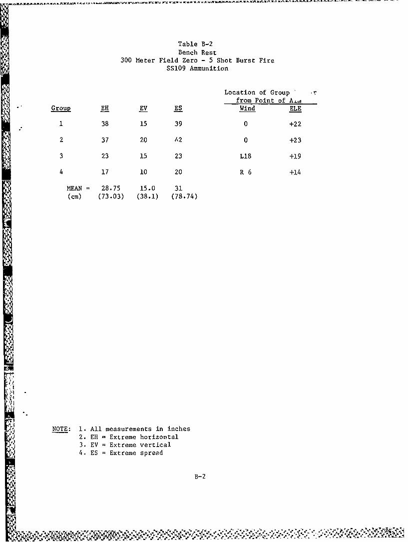
Table B-2Bench Rest
300 Meter Field Zero - 5 Shot Burst FireSS109 Ammunition
Location of Group r
from Point of A.,Group EH EV ES Wind ELE
1 38 15 39 0 +22
2 37 20 1,2 0 +23
3 23 15 23 L18 +19
4 17 10 20 R 6 +14
MEAN = 28.75 15.0 31(cm) (73.03) (38.1) (78.74)
! NOTE: 1. All measurements in inches
I 2. Ell = Extreme horizontal
3. EV = Extreme verticalS4. ES = Extreme sra
B-2
N4'N
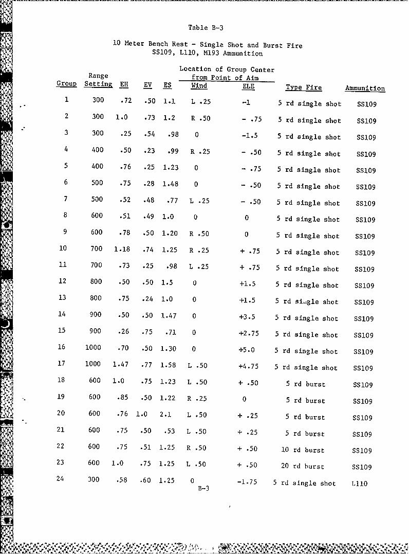
Table B-3
10 Meter Bench Rest - Single Shot and Burst FireSS109, LIl0, M193 Ammunition
Location of Group Center
G o pet nE V E Wind ELE TypFieA mun tioRange from Point of Aim
Group Setting EH EV ES Win -L Type Fire Ammunition
1 300 .72 .50 1.1 L .25 -1 5 rd single shot SS109
2 300 1.0 .73 1.2 R .50 - .75 5 rd single shot SS109
3 300 .25 .54 .98 0 -1.5 5 rd single shot SSI.09
4 400 .50 .23 .99 R .25 - .50 5 rd single shot SS109
5 400 .76 .25 1.23 0 - .75 5 rd single shot SS109
M 6 500 .75 .28 1.48 0 - .50 5 rd single shot SS109
7 500 .52 .48 .77 L .25 - .50 5 rd single shot SS109
8 600 .51 .49 1.0 0 0 5 rd single shot SS109
9 600 .78 .50 1.20 R .50 0 5 rd single shot SS109
10 700 1.18 .74 1.25 R .25 + .75 5 rd single shot SS109
11 700 .73 .25 .98 L .25 + .75 5 rd single shot SS109
12 800 .50 .50 1.5 0 +1.5 5 rd single shot SS109' 13 800 .75 .24 1.0 0 +1.5 5 rd si-igle shot SS109
14 900 .50 .50 1.47 0 +3.5 5 rd single shot SS109
15 900 .26 .75 .71 0 +2.75 5 rd single shot SS109
16 1000 .70 .50 1.30 0 +5.0 5 rd single shot SS10917 1000 1.47 .77 1.58 L .50 +4.75 5 rd single shot SS109
18 600 1.0 .75 1.23 L .50 + .50 5 rd burst SS109
19 600 .85 .50 1.22 R .25 0 5 rd burst SS109
20 600 .76 1.0 2.1 L .50 + .25 5 rd burst SS109
21 600 .75 .50 .53 L .50 + .25 5 rd burst SS109
22 600 .75 .51 1.25 R .50 + .50 10 rd burst SS109
23 600 1.0 .75 1.25 L .50 + .50 20 rd burst SS10924 300 .58 .60 1.25 0 -1.75 5 rd single shot LIO
B-3
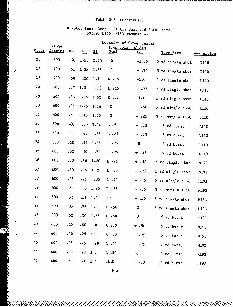
Table B-3 (Continued)
10 Meter Bench Rest - Single Shot and Burst FireSS109, LI0, M193 Ammunition
Location of Group CenterRange from Point of AimGroup Setting EH EV ES Wind ELE Type Fire Ammunition
25 300 .50 1.20 2.50 0 -1.75 5 rd single shot LII0
26 400 .51 1.23 1.75 0 - .75 5 rd single shot L110
27 400 .50 .26 1.5 R .25 -1.0 5 rd single shot LII0
28 500 .97 1.0 1.76 L .25 - .75 5 rd single shot LII0
29 500 .53 .75 1.52 R .25 -1.0 5 rd single shot L110
30 600 .26 1.25 1.76 0 + .50 5 rd single shot LIlO
31 500 .50 1.15 1.65 0 - .25 5 rd single shot LIlO
32 600 .60 .50 1.24 L .50 + .50 5 rd burst LilO
33 600 .35 .60 .75 L .25 + .50 5 rd burst L110
34 600 .50 .55 1.25 L .25 0 5 rd burst LllO
35 600 .52 .50 .75 L .25 + .25 5 rd burst LIIO
36 600 .60 .50 1.26 L .75 + .50 5 rd single shot M193
37 600 .50 .25 1.25 L .50 - .25 5 rd single shot M193
38 600 .25 .25 .85 L .50 - .25 5 rd single shot M193
39 600 .60 .50 1.35 L .25 - .55 5 rd single shot M193
40 600 .52 .51 1.0 0 - .50 5 rd single shot M193
41 600 .35 .76 1.1 L .50 0 5 rd single shot M193
. 42 600 .52 .50 1.35 L .50 0 5 rd burst M19343 600 .25 .60 1.0 L .50 + .50 5 rd burst M193
I N 44 600 .50 .25 1.1 L .50 + .25 5 rd burst M193
45 600 .85 .25 .98 L .50 + .25 5 rd burst M193
46 600 .30 .28 1.2 L .50 0 5 rd burst M193
47 600 .53 .71 1.4 L1.0 + .50 10 rd burst M193
B-4
$I
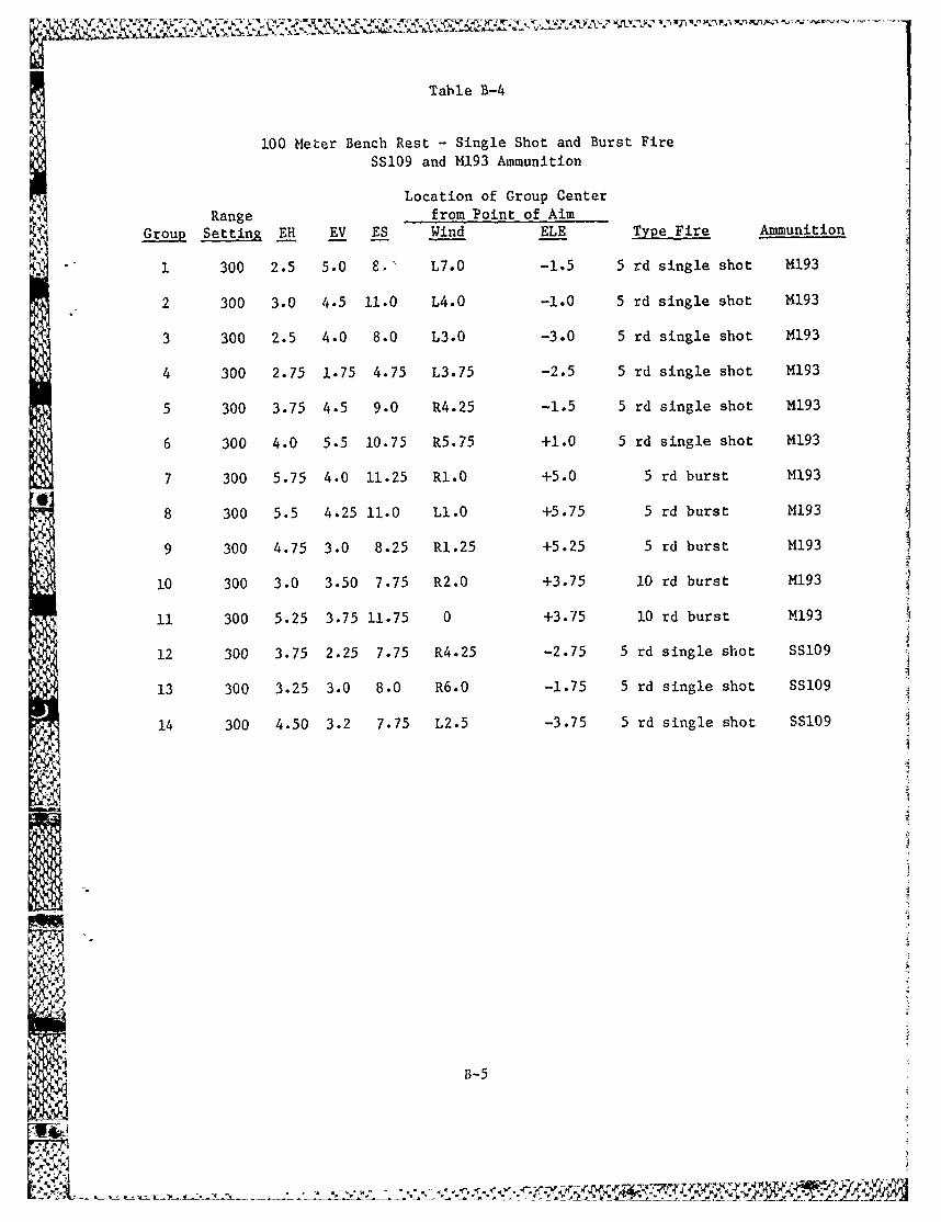
Table B-4
100 Meter Bench Rest - Single Shot and Burst Fire
SS109 and M193 Ammunition
Location of Group Center
Range from Point of AimGroup Setting EH EV ES Wind ELE Type Fire Ammunition
1 300 2.5 5.0 8, L7.0 -1.5 5 rd single shot M193
2 300 3.0 4.5 11.0 L4.0 -1.0 5 rd single shot M193
3 300 2.5 4.0 8.0 L3.0 -3.0 5 rd single shot M193
4 300 2.75 1.75 4.75 L3.75 -2.5 5 rd single shot M193
5 300 3.75 4.5 9.0 R4.25 -1.5 5 rd single shot M193
6 300 4.0 5.5 10.75 R5.75 +1.0 5 rd single shot M193
7 300 5.75 4.0 11.25 R1.0 +5.0 5 rd burst M193
8 300 5.5 4.25 11.0 LI.0 +5.75 5 rd burst M193
9 300 4.75 3.0 8.25 R1.25 +5.25 5 rd burst M193
10 300 3.0 3.50 7.75 R2.0 +3.75 10 rd burst M193
10 300 5.25 3.75 11.75 0 +3.75 10 rd burst M193
12 300 3.75 2.25 7.75 R4.25 -2.75 5 rd single shot SS109
13 300 3.25 3.0 8.0 R6.0 -1.75 5 rd single shot SS109
14 300 4.50 3.2 7.75 L2.5 -3.75 5 rd single shot SS109
B-5
%2 ~ J'. __
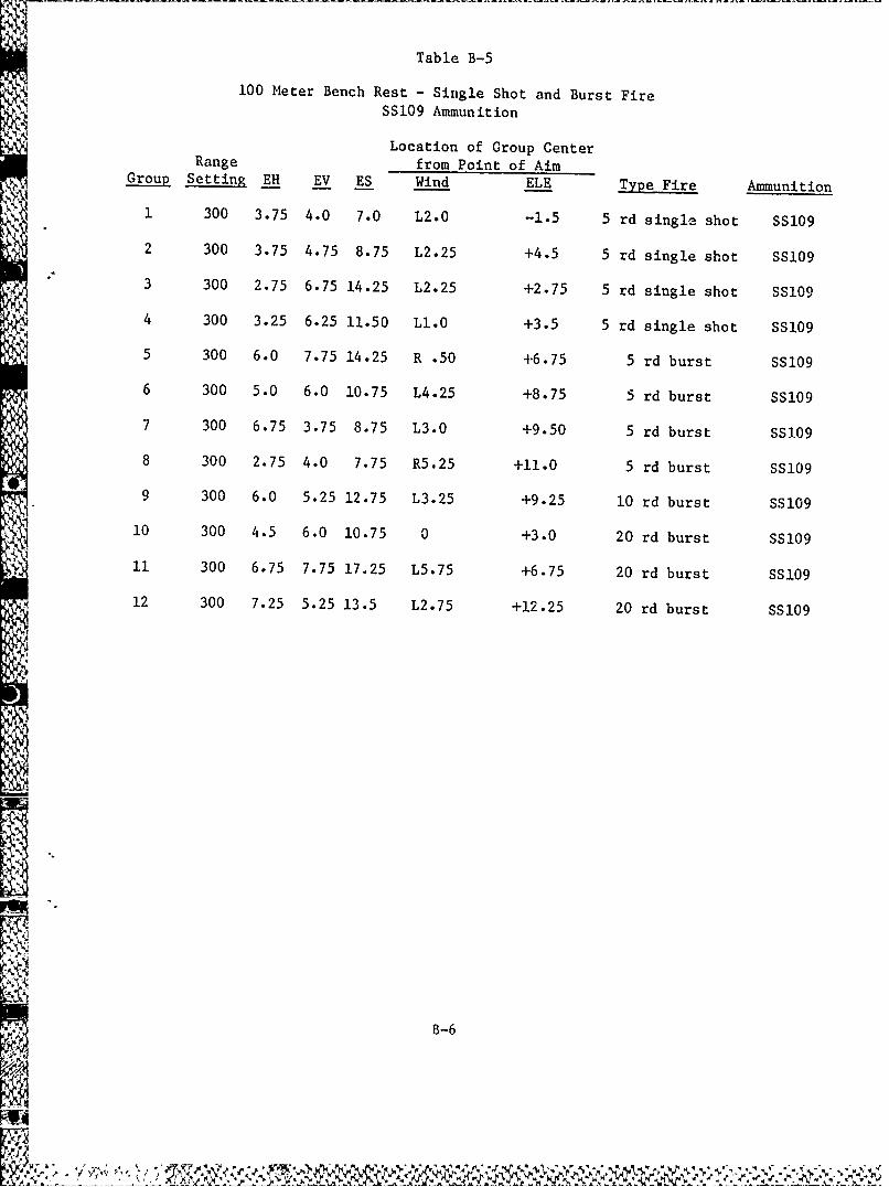
Table B-5100 Meter Bench Rest - Single Shot and Burst Fire
SS109 Ammunition
Location of Group CenterRange from Point of Aim
Group Setting EH EV ES Wind ELE Type Fire Ammunition
1 300 3.75 4.0 7.0 L2.0 -1.5 5 rd single shot SS109
2 300 3.75 4.75 8.75 L2.25 +4.5 5 rd single shot SS109
3 300 2.75 6.75 14.25 L2.25 +2.75 5 rd single shot SS109
4 300 3.25 6.25 11.50 L1.0 +3.5 5 rd single shot SS109
'' 5 300 6.0 7.75 14.25 R .50 +6.75 5 rd burst SS109
6 300 5.0 6.0 10.75 L4.25 +8.75 5 rd burst SS109
7 300 6.75 3.75 8.75 L3.0 +9.50 5 rd burst SS109
8 300 2.75 4.0 7.75 R5.25 +11.0 5 rd burst SS109
9 300 6.0 5.25 12.75 L3.25 +9.25 10 rd burst SS109
10 300 4.5 6.0 10.75 0 +3.0 20 rd burst SS109
' 11 300 6.75 7.75 17.25 L5.75 +6.75 20 rd burst SS109
12 300 7.25 5.25 13.5 L2.75 +12.25 20 rd burst SS109
B-6
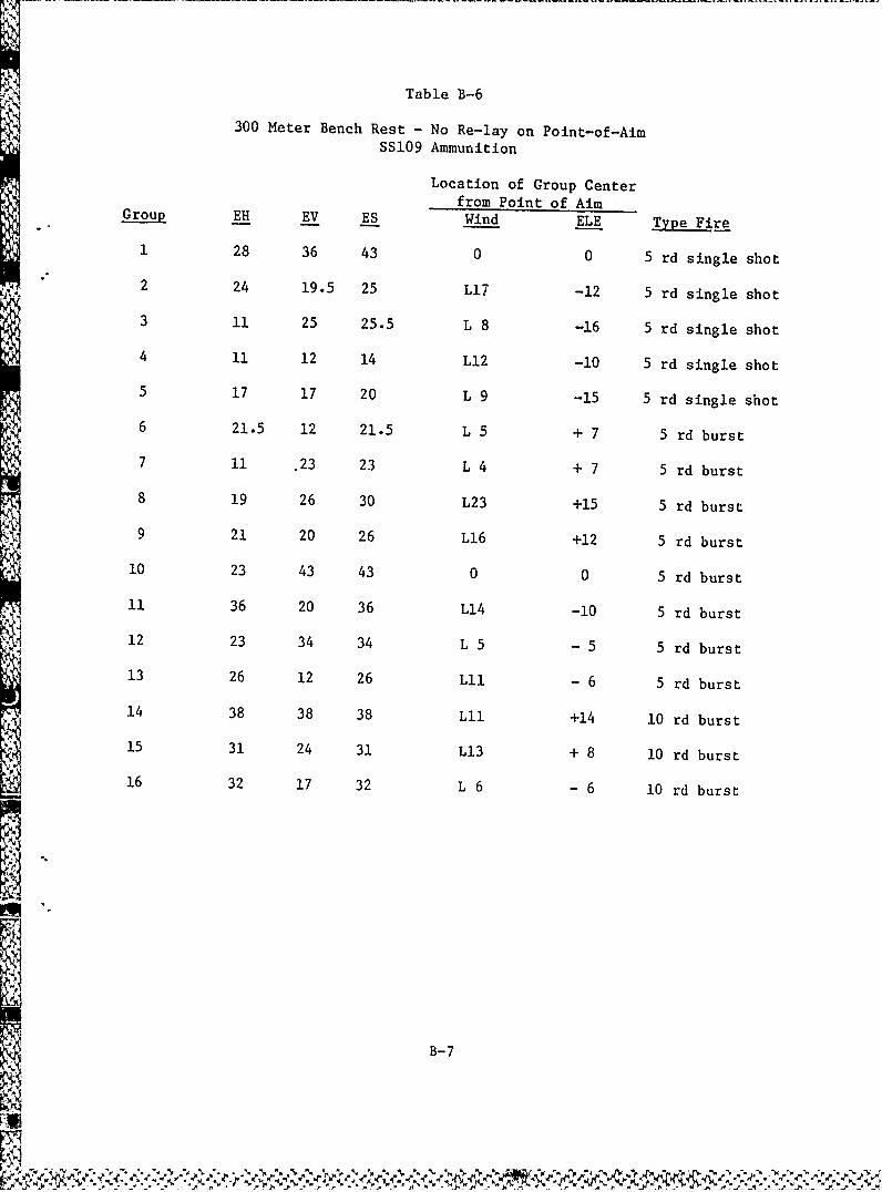
Table B-6
300 Meter Bench Rest - No Re-lay on Point-of-Aim
SSi09 Ammunition
Location of Group Center
from Point of AimGroup EH EV ES Wind ELE Type Fire
1 28 36 43 0 0 5 rd single shot
2 24 19.5 25 L17 -12 5 rd single shot
3 ii 25 25.5 L 8 -16 5 rd single shot
4 11 12 14 L12 -10 5 rd single shot
5 17 17 20 L 9 -15 5 rd single shot
6 21.5 12 21.5 L 5 + 7 5 rd burst
7 11 .23 23 L 4 + 7 5 rd burst
8 19 26 30 L23 +15 5 rd burst
9 21 20 26 L16 +12 5 rd burst
10 23 43 43 0 0 5 rd burst
11 36 20 36 Li4 -10 5 rd burst
12 23 34 34 L 5 - 5 5 rd burst
13 26 12 26 LII - 6 5 rd burst
14 38 38 38 Lii +14 l0 rd burst15 31 24 31 L13 + 8 10 rd burst16 32 17 32 L 6 -6 10 rd burst
B-7
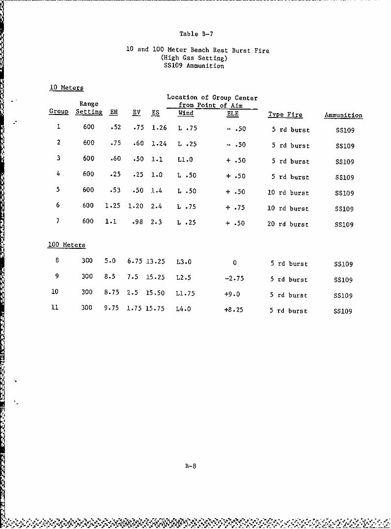
Table B-7
10 and 100 Meter Bench Rest Burst Fire(High Gas Setting)SS109 Ammunition
10 MetersLocation of Group Center
Range from Point of AimGroup Setting EH EV ES Wind ELE Type Fire Ammunition
1 600 .52 .75 1.26 L .75 - .50 5 rd burst SS109
2 600 .75 .60 1.24 L .25 .50 5 rd burst SS109
3 600 .60 .50 1.1 L1.0 + .50 5 rd burst SS109
4 600 .25 .25 1.0 L .50 + .50 5 rd burst SS109
5 600 .53 .50 1.4 L .50 + .50 10 rd burst SS109
6 600 1.25 1.20 2.4 L .75 + .75 10 rd burst SS109
7 600 1.1 .98 2.3 L .25 + .50 20 rd burst SS109
100 Meters
8 300 5.0 6.75 13.25 L3.0 0 5 rd burst SS109
9 300 8.5 7.5 15.25 L2.5 -2.75 5 rd burst SS109
10 300 8.75 2.5 15.50 Ll.75 +9.0 5 rd burst SS109
11 300 9.75 1.75 15.75 L4.0 +8.25 5 rd burst SS109
B-8
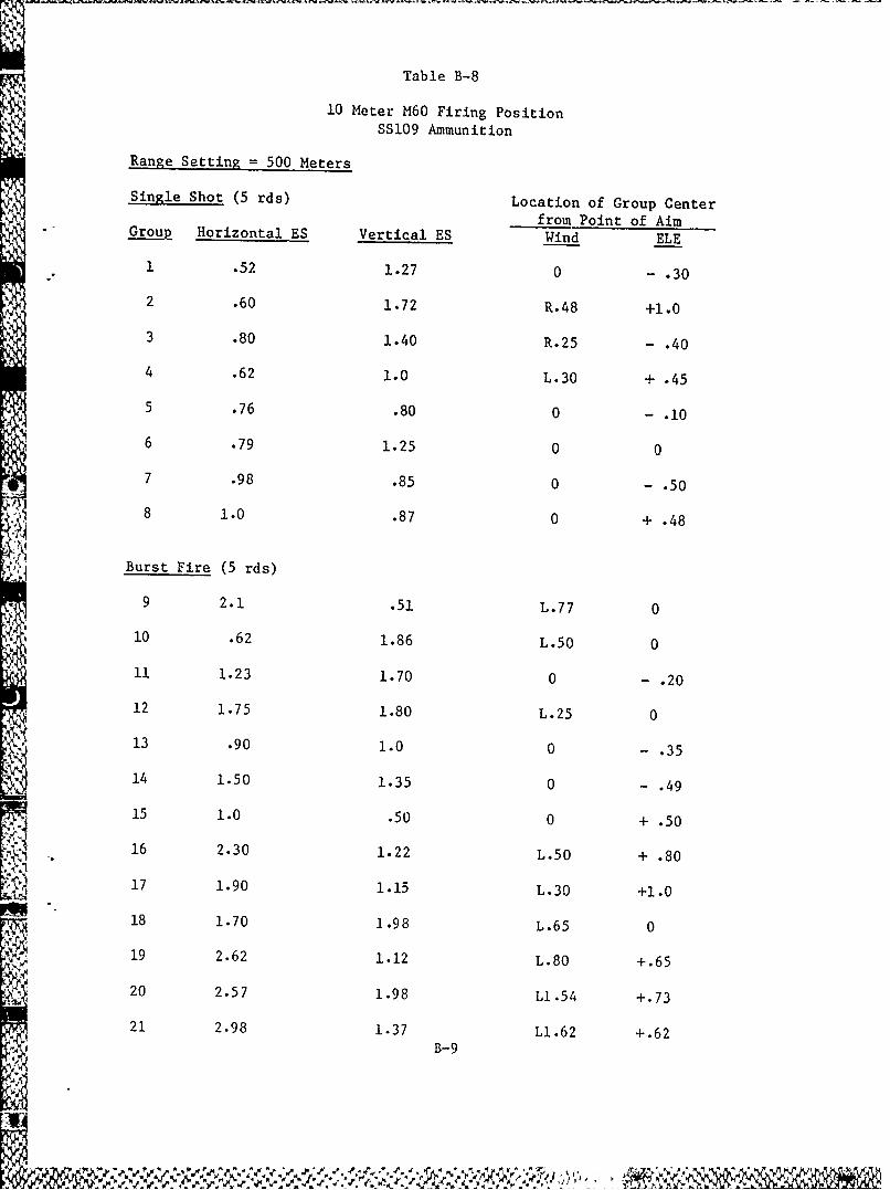
Table B-8
10 Meter M60 Firing PositionSS109 Ammunition
Range Setting = 500 Meters
Single Shot (5 rds) Location of Group Center
from Point of Aimv Group Horizontal ES Vertical ES Wind ELE
1 .52 1.27 0 - .30
2 .60 1.72 R.48 +1.0
3 .80 1.40 R.25 - .40
4 .62 1.0 L.30 + .45
5 .76 .80 0 - .10
6 .79 1.25 0 0
7 .98 .85 0 - .50
8 1.0 .87 0 + .48
Burst Fire (5 rds)
9 2.1 .51 L.77 0
10 .62 1.86 L.50 0
11 1.23 1.70 0 - .20
12 1.75 1.80 L.25 0
13 .90 1.0 0 - .35
14 1.50 1.35 0 - .49
15 1.0 .50 0 + .50
16 2.30 1.22 L.50 + .80
17 1.90 1.15 L.30 +1.0
18 1.70 1.98 L.65 0S19 2.62 1.12 L.80 +.65
i 20 2.57 1.98 Ll.54 +. 73
21 2.98 1.37 Ll-62 +.62) . . !B - 9
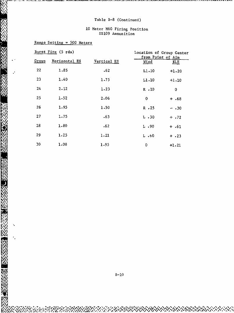
Table B-8 (Continued)
10 Meter M60 Firing PositionSS109 Ammunition
Range Setting = 500 Meters
Burst Fire (5 rds) Location of Group Centerfrom Point of Aim
Group Horizontal ES Vertical ES Wind ELE
22 1.85 .62 Ll.10 +1.20
23 1.40 1.75 L1.i0 +1.10
24 2.12 1.23 R .10 0
25 1.52 2.06 0 + .68
26 1.95 1.50 R .25 - .30
27 1.75 .63 L .30 + .72
28 1.80 .62 L .90 + .61
29 1.25 1.21 L .60 + .23
30 1.08 1.95 0 +1.21
B-10
IN

Table B-9
10 Meter M60 Firing PositionM193 Ammunition
Single Shot Location of Group CenterRange from Point of Aim
A Group Setting Horizontal ES Vertical ES Wind ELE
14) 1 600 1.2 .25 0 + .75
2 600 .75 .73 L .22 + .51
3 500 .60 .52 0 + .25
4 500 .77 .75 0 + .25
5 500 .73 .28 0 0
6 500 1.1 .85 0 - .35
7 500 .75 1.0 0 0
UBurst Fire
8 600 2.1 .75 0 + .51
9 600 .75 1.4 L .72 + .25
10 600 .60 .75 L1•0 +124
11 600 1.50 .71 Ll35 +1.25
12 600 1.52 .75 0 +1.2
13 600 1.25 .73 L .47 +1.25
14 600 1.23 .50 L .50 +1.78
15 600 .85 1.22 L .51 +1.0
16 600 1.75 .75 L .25 + .98
17 600 1.35 .98 R .23 +1.0
18 600 2.0 1.5 LI.0 +1.46
19 600 1.2 .85 L .76 + .75
20 600 .75 1.75 0 + .57
21 600 1.20 2.4 Rl.l - .2522 600 1.0 1.0 0 +1.16
B-il
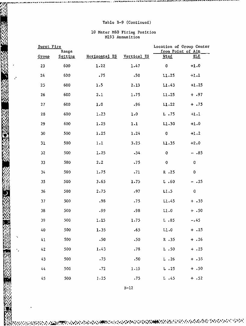
Table B-9 (Continued)
10 Meter M60 Firing PositionM193 Ammunition
Burst Fire Location of Group CenterRange from Point of Aim
Group Settin& Horizontal ES Vertical ES Wind ELE
23 600 1.22 1.47 0 +1.0
24 600 .75 .50 L.25 +1.1
25 600 1.5 2.13 L.43 +1.25
26 600 2.1 1.75 L.25 + .97
27 600 1.0 .96 L.22 + .75
28 600 1.23 1.0 L .75 +1.1
29 600 1.25 1.1 L1.30 +1.0
30 500 1.25 1.24 0 +1.2
31 500 1.1 3.25 L1.35 +2.0
32 500 1.25 .54 0 - .85
33 500 2.2 .75 0 0
34 500 1.75 .71 R .25 0
35 500 3.65 1.75 L .60 - .25
36 500 2.75 .97 L1.5 0
37 500 .98 .75 L1.45 + .35
38 500 .99 .98 L1.0 + .50
39 500 1.15 1.75 L .85 -.45
40 500 1.35 .65 L1.0 + .25
41 500 .50 .50 R .35 + .26
42 500 1.43 .78 L .50 + .25
43 500 .75 .50 L .26 + .35
44 500 .72 1.15 L .25 + .50
45 500 1.25 .75 L .45 + .52
B-12
:N%
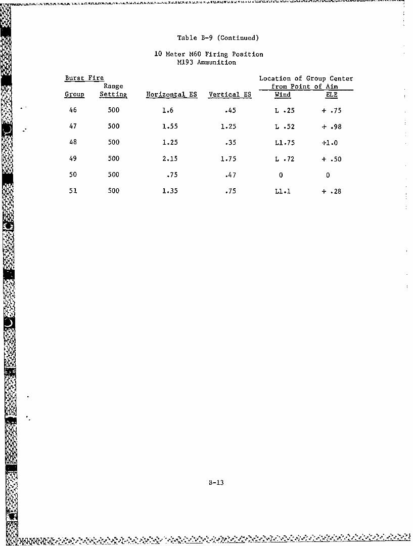
Table B-9 (Continued)
10 Meter M60 Firing PositionM193 Ammunition
Burst Fire Location of Group CenterRange from Point of Aim
Group Setting Horizontal ES Vertical ES Wind ELE
46 500 1.6 .45 L .25 + .75
47 500 1.55 1.25 L .52 + .98
48 500 1.25 .35 Ll.75 +1.0
49 500 2.15 1.75 L .72 + .50
50 500 .75 .47 0 0
51 500 1.35 .75 L1.1 + .28
B-1
I ! 1B-13
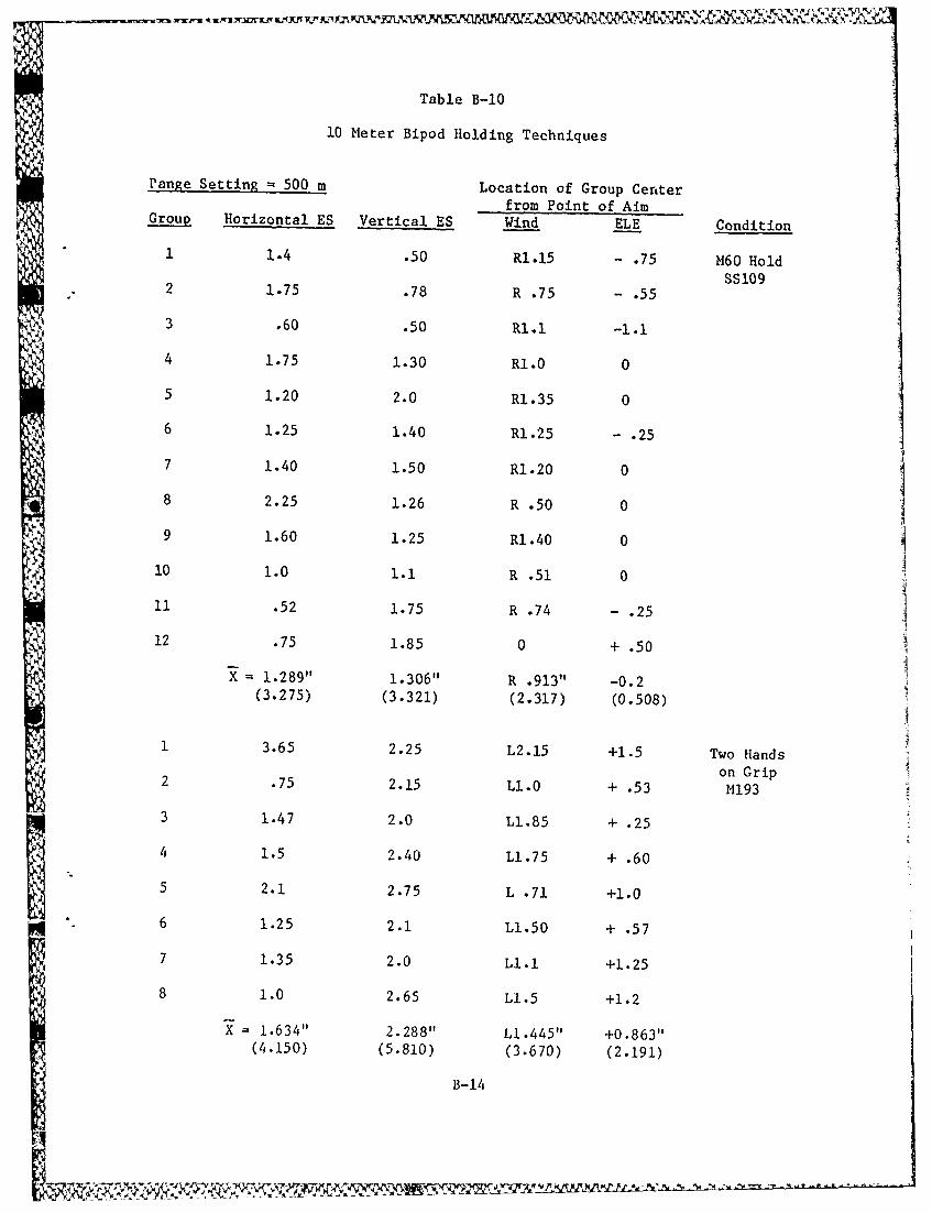
Table B-10
10 Meter Bipod Holding Techniques
Pange Setting 500 m Location of Group Center
from Point of AimGroup Horizontal ES Vertical ES Wind ELE Condition
1 1.4 .50 R1.15 - .75 M60 Hold
SS1092 1.75 .78 R .75 - .55
3 .60 .50 R1.1 -1.1
4 1.75 1.30 Rl.0 0
5 1.20 2.0 R1.35 0
6 1.25 1.40 R1.25 - .25
7 1.40 1.50 R1.20 0
8 2.25 1.26 R .50 0
9 1.60 1.25 R1.40 0
10 1.0 1.1 R .51 0
1i .52 1.75 R .74 .2512 .75 1.85 0 + .50
X=1.289" 1.306" R .913" -0.2(3.275) (3.321) (2.317) (0.508)
1 3.65 2.25 L2.15 +1.5 Two Hands
on Grip2 .75 2.15 L1.0 + .53 M193
3 1.47 2.0 Ll.85 + .25
4 1.5 2.40 Ll.75 + .60
5 2.1 2.75 L .71 +1.0
6 1.25 2.1 Ll.50 + .57
7 1.35 2.0 LI.1 +1.25
8 1.0 2.65 LI.5 +1.2
X 1.634" 2.288" LI.445" +0.863"(4.150) (5.810) (3.670) (2.191)
B-14
21I
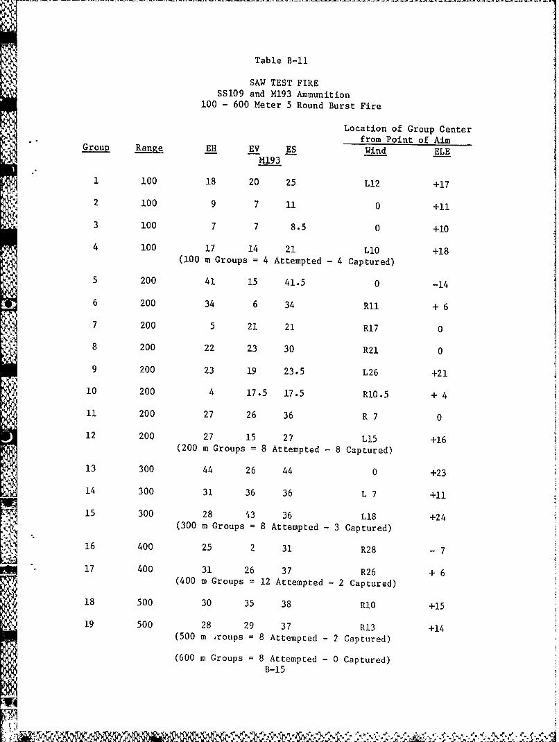
Table B-i
SAW TEST FIREI SS109 and M193 Ammunition100 - 600 Meter 5 Round Burst Fire
Location of Group Centerfrom Point of AimGroup Range EH EV ES Wind ELE
M193
1 100 18 20 25 L12 +17
2 100 9 7 11 0 +11
3 100 7 7 8.5 0 +10
4 100 17 14 21 L10 +18i (100 m Groups = 4 Attempted - 4 Captured)
5 200 41 15 41.5 0 -14
6 200 34 6 34 RII + 6
7 200 5 21 21 R17 0
8 200 22 23 30 R21 0
9 200 23 19 23.5 L26 +21
10 200 4 17.5 17.5 R10.5 + 4
11 200 27 26 36 R 7 0
12 200 27 15 27 L15 +16(200 m Groups = 8 Attempted - 8 Captured)
13 300 44 26 44 0 +23
14 300 31 36 36 L 7 +11NE 15 300 28 43 36 L18 +24
(300 m Groups 8 Attempted -3 Captured). 16 400 25 2 31 R28 7
17 400 31 26 37 R26 + 6
(400 m Groups = 12 Attempted -2 Captured)
18 500 30 35 38 RI0 +15
19 500 28 29 37 R13 +14(500 m roups = 8 Attempted - 2 Captured)
(600 m Groups 8 Attempted - 0 Captured)B-15
I -(~
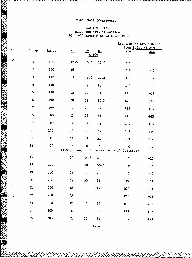
Table B-i (Continued)
SAW TEST FIRE
SS109 and M193 Ammunition100 - 600 Meter 5 Round Burst Fire
Location of Group Centerfrom Point of Aim
Group Range EH EV ES Wind ELE;i --SS109
1 100 12.5 5.5 13.5 R 4 + 9
2 100 16 13 16 R 6 + 7
3 100 15 6.5 15.5 R 7 + 7
4 100 5 9 10 L 2 +10
5 100 12 30 31 RIO +19
6 100 28 12 29.5 L20 +16
7 100 17 22 24 L12 + 9
8 100 25 22 25 LI5 +13
9 100 9 8 14 R 4 + 5
10 100 13 21 25 L 9 +14
11 100 17 7 21 R13 +4
12 100 5 0 12 0 - 2(100 m Groups = 12 Attempted - 12 Captured)
17 200 24 14.5 27 L 2 +16
18 200 35 10 35.5 0 + 8
19 200 23 13 23 L 6 + 5
20 200 44 30 55 L22 +21
21 200 18 8 19 R14 +11
22 200 25 16 29 R13 +11
23 200 12 4 22 R 8 - 3
24 200 14 16 20 R12 + 9
25 200 31 25 51 R 7 +23
B-16
>1%
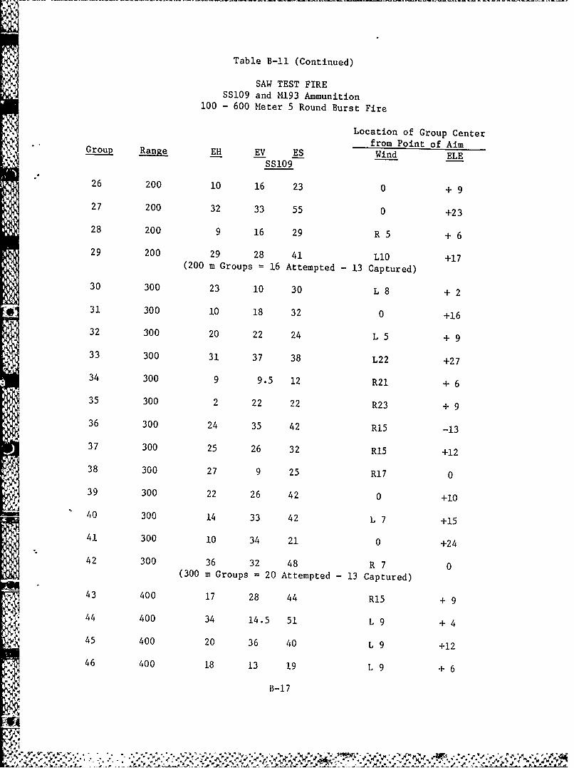
Table B-li (Continued)
SAW TEST FIRESSI09 and M193 Ammunition
100 - 600 Meter 5 Round Burst Fire
Location of Group Centerfrom Point of Aim--SS 109-Group Range EH- EV ES Wrmin ELEAi
26 200 10 16 23 0 + 9
27 200 32 33 55 0 +23
28 200 9 16 29 R 5 + 6
29 200 29 28 41 L1O +17(200 m Groups = 16 Attempted - 13 Captured)
30 300 23 10 30 L 8 + 2
31 300 10 18 32 0 +16
32 300 20 22 24 L 5 + 9
33 300 31 37 38 L22 +27
34 300 9 9.5 12 R21 + 6
35 300 2 22 22 R23 + 9
36 300 24 35 42 Ri5 -13
37 300 25 26 32 RI5 +12
38 300 27 9 25 R17 0
44 39 300 22 26 42 0 +10
'40 300 14 33 42 L 7 +15
41 300 10 34 21 0 +24
42 300 36 32 48 R 7 0(300 m Groups = 20 Attempted - 13 Captured)
43 400 17 28 44 RI5 + 9
44 400 34 14.5 51 L9 +445 400 20 36 40 L 9 +12
46 400 18 13 19 L 9 + 6
SB-17
2.,,4f - ~2-~.-
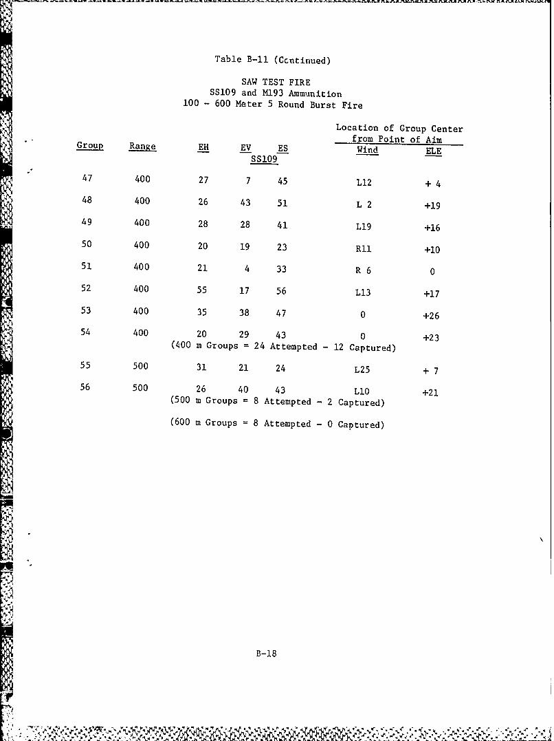
Table B-i (Ccntinued)
SAW TEST FIRESS109 and M193 Ammunition
100 - 600 Meter 5 Round Burst Fire
Location of Group Centerfrom Point of Aimp Ran EH EV ES Wind ELE
SSI09
47 400 27 7 45 L12 + 4
48 400 26 43 51 L 2 +19
49 400 28 28 41 L19 +16
50 400 20 19 23 RII +10
51 400 21 4 33 R 6 0
52 400 55 17 56 L13 +17
53 400 35 38 47 0 +26
54 400 20 29 43 0 +23(400 m Groups = 24 Attempted -12 Captured)
55 500 31 21 24 L25 + 7
56 500 26 40 43 L10 +21(500 m Groups = 8 Attempted - 2 Captured)
(600 m Groups = 8 Attempted - 0 Captured)
B-18
7'V -4* N r y
Appendix C
ARMY MARKSMANSHIP UNIT
SAW FIRING TEST--COMMENTS
1. In order to obtain best results, the weapon must be precisely zeroed by
each firer. It is also recommended that zeroes be obtained at a range of
300 meters. Zeroing to point-of-aim at 10 meters with sights at 500
meters resulted in a great variation in point of impact at actual ranges.
Accuracy of a new M249 SAW does not appear to be any better than an old,
extensively used SAW. The only difference is that the rate of fire of
the new weapon is slower and allows the firer to control he length of
burst better. This allows the firer to conserve ammunition by firing 2
to 3 rounds burst ana, therefore, fire more 2 to 3 round bursts and
obtain more hits. The rate of fire is too fast, even on new guns and the
weapon is too light to be controlled well while firing.
2. The length of burst required to hit an "E" type silhouette at ranges of
300 meters or less should not exceed 2 to 3 rounds. Firing longer bursts
wastes ammunition and does not increase hit probability. At 400 meters,
the same firing techniques should be used but. may require multiple bursts
to obtain a hit on the silhouette. At ranges exceeding 400 meters,obtaining a hit on an "E" type silhouette is largely a matter of luck and
engaging targets at these ranges is not recommended.
3. The bipod ,ms to be .oo flexible and causes difficulty in obtaining and
mintaining a good firing position. Firing from a tripod does not seem
;[ C - I
AI.to have a significant effect in improving accuracy over the bipod firing
method.
4. The tracer and ball amunition are not ballistically matched. The tracer
impacts approximately 2 to 3 feet higher than ball at 550 meters when
fired from a machine rest. The same appear to be true when fired from a
bipod or tripod. The tracer is not visible to the firer at ranges
shorter than 500 to 600 meters during daylight hours and is seldom
visible to an observer at less than 400 meters.
5. The front sight base is easily loosened and was loose on one of the
weapons fired. The hood surrrounding the front sight requires the firer
to force his head to the rear in order to prevent the hood from obscuring
the rear sight aperture and causing sight alignment problems. The hood
also greatly reduces the firer's ability to observe tracers bullet
impacts, or the immediate area around the target. It is recommended that
hoods be removed and sight guards be installed or, if this is not
possible, the stock be lengthened to reduce the possibility of sight
alignment error.
6. The rear sight aperture has approximately I to 4 mils sideplay. This
looseness should be removed as it causes great difficulty in zeroing or
obtaining consistent, first burst hits on target. The rear sight has a
loose aperture and is constructed of thin, flimsy sheet metal. Because
-f the looseness, construction, and the relatively exposed way in which
C-2
it is mounted, the rear sight is susceptible to being easily damaged.
7. The aluminum receiver is more susceptible to wear than a receiver made of
steel. This is especially true in the receiver ring area where the
barrel connects to the receiver. As barrels are changed or removed for
cleaning, this area may wear more rapidly than steel and cause looseness
between the barrel and receiver. This will further degrade accuracy and
in extreme cases may cause function problems.
8. The barrel is not constructed for long life, especially when one
considers the rate of fire. The chamber and throat areas are not
stellite lined to prevent erosion. Since double base spherical (ball)
powder is used in the cartridge, the muzzle end of the barrel will heat
up first and may wear as fast or faster than the throat area. The muzzle
end of the barrel, however, is much smaller than the chamber area and
does not dissipate heat as well. This may cause excessive wear/erosion
at the muzzle area which is the area most critical to accuracy.
9. The two-speed rate of fire is unnecessary as the rate of fire ig already
too high on slow rate. If the high rate position is there to allow
functioning in cold weather or when heavily fouled, then the action may
J be underpowered and/or may suffer from some other fundamental defect. In
any case, the rate of fire selector and target engagement techniques, as
concerns marksmanship, only serves to increase the cost of manufacture.
C-3
Nf 5
10. The weapon is constructed so it may be rapidly disassembled for cleaning
or repair, except in the case of the firing pin which is one of the most
critical parts of any weapon. The firing pin, if broken, cannot be
changed by the operator as it is held in place by a roll pin. Removal of
the roll pin requires a hammer and the appropriate sized drift pin plus a
replacement roll pin if the first pin is deformed during removal. It is
recommended that a solid steel, captive pin, like the pin which secures
the bolt carrier to the operating rod, replace roll pin, which secures
the firing pin. It is also recommended that the firing pin be modified
to a double ended (reversible) configuration as used in the Mendoze RM-2
light machinegun. This would facilitate rapid replacement by the
operator and eliminate the necessity to carry spare firing pins.
11. The weapon is basically well designed, except in the case of final
production engineering. In its current configuration, it is suitable as
a replacement for the bipod fired I-6AI squad automatic weapon, when
used at ranges not exceeding 400 meters. It is NOT, however, equal or
superior to the M60 general purpose machinegun in terms of effective
range or accuracy and probably not equal a to durability or sustained
fire capability.
SFC RECIITENWALD
USAMU, Fort Benning
c-4
--_