Embed Size (px)
Citation preview

1
DC Fan Speed Control PWM Signal Introduction
Wayne_ChenADDA RD Chief Engineer
[email protected] ext:326

2
Topical:
1. Speed Control Fan Configuration (old version)
2. What is PWM Signal ?
3. PWM Control Methods Introduction
4. PWM Fan Specification
5. PWM Fan Sample
6. Q & A

3
1. Speed Control Fan Structure (old version)
Vcc
Fan
1-1. Use ON/OFF control by Transistor1-1. Use ON/OFF control by Transistor
AdvantageAdvantage::
I.I. Easy design and control method Easy design and control method
II.II. Price cheaper.Price cheaper.
Disadvantage :Disadvantage :
I.I. Power Dissipation is a design Power Dissipation is a design issue. issue.
II.II. Not use friendly. Not use friendly.

4
2. What is PWM Signal ?• PWM(Pulse Width Modulation): It’s a fixed frequency
and pulse modulated for fan speed control. • Whenever change the duty cycle, the fan speed will be
changed by system requirement.
Figure : PWM Control Signal
Duty Cycle 20%Lowest Speed
Duty Cycle 50%Middle Speed
Duty Cycle 80%High Speed
Cycle
Duty Cycle
Duty Cycle = DT / T (%)
(DT)
The Purpose are :The Purpose are :
1. The power dissipation will be saving.1. The power dissipation will be saving.
2. And the working time will be increasing if the battery 2. And the working time will be increasing if the battery could not be charged outside. (especially NB system)could not be charged outside. (especially NB system)

5
3. PWM control Methods introduction 3-1Speed Control Fan Structure (old version)
Fan
+Vcc
DisadvantageDisadvantage::
I.I. Poor Reliability ( Transistor are Poor Reliability ( Transistor are On/OFF continuously)On/OFF continuously)
II.II. Error judgment of tachometer Error judgment of tachometer signal.signal.
AdvantageAdvantage::
I.I. Easy design and control method Easy design and control method
II.II. Price cheaper.Price cheaper.
Use ON/OFF control by TransistorUse ON/OFF control by Transistor

6
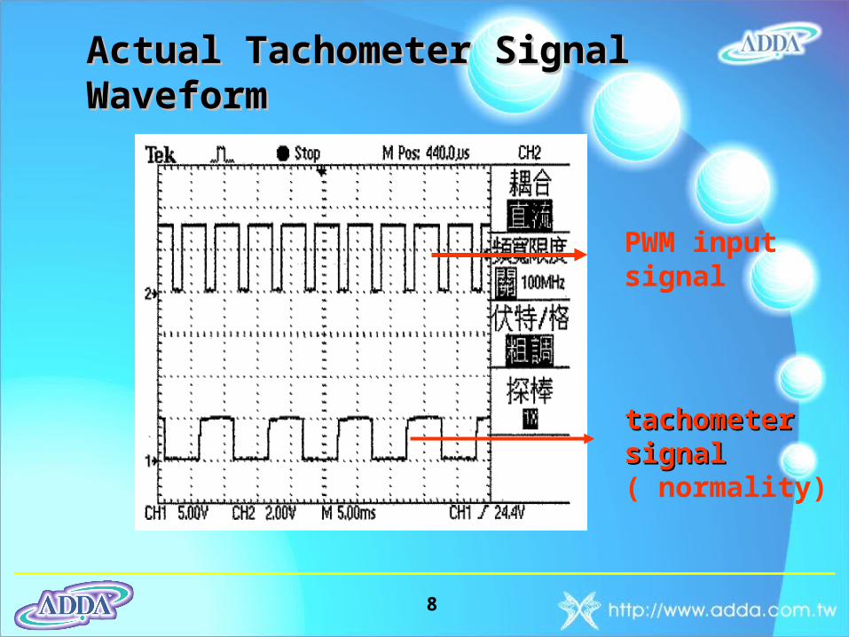
Actual Tachometer Signal Waveform
PWM input signal
Error judgment Error judgment of tachometer of tachometer signalsignal

7
AdvantageAdvantage::
I.I. The better The better Reliability Reliability
II.II. RPM StableRPM Stable
III.III. Power efficiency Power efficiency saving.saving.
DisadvantageDisadvantage::
I.I. Cost expensive. Cost expensive.
II.II. Control Circuit Control Circuit ComplexComplex
OPAIntegrationCircuit
PWMSignalInput
Vcc
Fan
3-2. Regulator Control Fan Configuration3-2. Regulator Control Fan Configuration
(Current version For Notebook <Three Wires>)(Current version For Notebook <Three Wires>)
8
PWM input signal
tachometer tachometer signalsignal ( normality)
Actual Tachometer Signal WaveformActual Tachometer Signal Waveform

9
3-3. Control PWM Fan Configuration<Four Wires>
PWM Fan
Vcc
Tachometer Output Signal
Low Speed
High SpeedPWM
Signal Input
System Motherboard
Low Speed
High Speed
Vcc
OscillatorComparator
IntegrationCircuit
PWMSignalInput
Driver DCMotorBlock
ControllerBlock
ReferenceVoltage
PWM control Configuration
System Fan

10
3-4. Next Generation Version PWM Control Fan: Type A
Type AType A
11
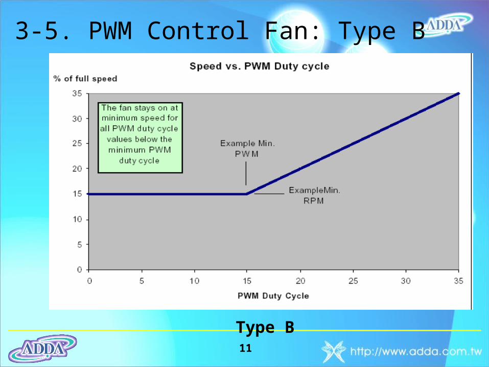
3-5. PWM Control Fan: Type B
Type B

12
4-1. PWM Input Signal Specification (from system)
• PWM Operating Frequency : 25kHz ± 5kHz
• Maximum Input Low Voltage (VIL-MAX) = 0.8V
• Minimum Input High Voltage (VIH-MIN) = 2.0V
• High Input Impedance (10K ohms at least )
(Consider Fan-In Issue, Driver Capability)
VIL-MAX=0.8V
VIH-MIN=2.0V
Frequency = 25kHz
InputImpedance

13
4-2. PWM Fan Specification• Operation Voltage : 5V or 12V ± 10% • Function: Locked Protection and Auto-restart• Apply the Open Collector or Open Drain
Tachometer Output Signal• Low Speed setting with 0~17% (or 20%) on Same
PRM level (Type B)
Open Collector Configuration
FG
Open Drain Configuration
FG
Vcc

14
5. PWM Fan sample5-1. Type A( For NB fan suggestion)
PWM Fan Duty Cycle v.s Speed6000rpm Model
0
500
1000
1500
2000
2500
3000
3500
4000
4500
5000
5500
6000
6500
0% 10% 20% 30% 40% 50% 60% 70% 80% 90% 100%
Duty Cycle
Spee
d
Fan Stop Duty Cycle
Fan Start_up Duty Cycle

15
5. PWM Fan sample5-2. Type A( All kind of fan could be used.)5-2. Type A( All kind of fan could be used.)
PWM Fan Duty Cycle v.s SpeedAD8025 Model
0
500
1000
1500
2000
2500
3000
3500
4000
0% 10% 20% 30% 40% 50% 60% 70% 80% 90% 100%
Duty Cycle
Sp
ee
d
Fan Stop Duty Cycle
Fan Start_up Duty Cycle
16
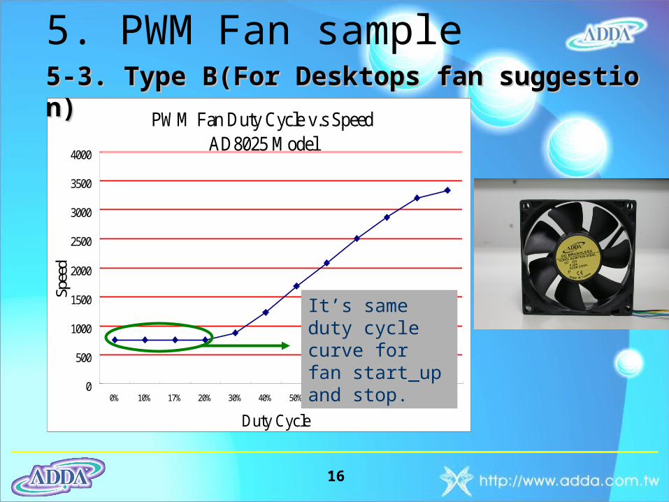
5. PWM Fan sample
PWM Fan Duty Cycle v.s SpeedAD8025 Model
0
500
1000
1500
2000
2500
3000
3500
4000
0% 10% 17% 20% 30% 40% 50% 60% 70% 80% 90% Full
Duty Cycle
Spee
d5-3. Type B(For Desktops fan suggestion)5-3. Type B(For Desktops fan suggestion)
It’s same duty cycle curve for fan start_up and stop.

17
6. Question & Answer (The End)