Embed Size (px)
Citation preview
Hager Companies139 Victor St
St Louis MO 63104Phoneensp(800) 325-9995Phoneensp(314) 772-4400
Faxensp(800) 782-0149Emailenspcustomerconnecthagercocom
Error Hyperlink reference not validThis MANU-SPECreg utilizes the Construction Specifications Institute (CSI) Project Resource Manual (PRM) including MasterFormattrade SectionFormattrade and PageFormattrade A MANU-SPEC is a manufacturer-specific proprietary product specification using the proprietary method of specifying applicable to project specifications and master guide specifications Optional text is indicated by brackets [ ] delete optional text in final copy of specification Specifier Notes precede specification text delete notes in final copy of specification Tradebrand names with appropriate product model numbers styles and types are used in Specifier Notes and in the specification text Article titled inchesAcceptable Material inches Metric conversion where used is soft metric conversion
This MANU-SPEC specifies a door hardware as manufactured by Hager Companies Revise MANU-SPEC section number and title below to suit project requirements specification practices and section content Refer to CSI MasterFormat for other section numbers and titles
SECTION 08 71 00 DOOR HARDWARE
Specifier NoteenspRevise paragraphs below to project requirements according to CSI 2004 MasterFormat and specifierrsquos practice
PART 1 GENERAL
101emspSUMMARY
AemspSection includes furnishing and installation of door hardware for doors specified in inchesHardware Sets inches and required by actual conditions Including screws bolts expansion shields electrified door hardware and other devices for proper application of hardware
Specifier NoteenspRevise Paragraph below to suit project requirements Add section numbers and titles per CSI MasterFormat and specifierrsquos practice
BemspRelated Requirements
Specifier NoteenspRevise Paragraph below to suit project requirements Add section numbers and titles per CSI MasterFormat and specifierrsquos practice
1 Section [______]2 Hardware for aluminum doors furnished under this Section but installed under Division 08 Openings3 Final replacement of cylinder cores to be installed by Owner4 Hold open wall magnets5 Electrified hardware furnished under this Section but installed by the security contractor
102emspREFERENCES
Specifier NoteenspDefine terms that are unique to this Section and are not provided elsewhere in the contract documentsInclude in this Article terms that are unique to the work result specified that may not be commonly known in the construction industry
AemspAmerican National Standards InstituteBuilders Hardware Manufacturers Association (ANSI)1 ANSIBHMA A1561 Butts amp Hinges2 ANSIBHMA A1562 Bored amp Preassembled Locks amp Latches3 ANSIBHMA A1563 Exit Devices4 ANSIBHMA A1564 Door ControlsmdashClosers5 ANSIBHMA A1565 Cylinders and Input Devices for Locks6 ANSIBHMA A1566 Architectural Door Trim
7 ANSIBHMA A1567 Template Hinge Dimensions8 ANSIBHMA A1568 Door ControlsmdashOverhead Stops and Holders9 ANSIBHMA A15610 Power Operated Pedestrian Doors10 ANSIBHMA A15612 Interconnected Locks amp Latches11 ANSIBHMA A15613 Mortise Locks amp Latches12 ANSIBHMA A15614 Sliding amp Folding Door Hardware13 ANSIBHMA A15615 Closer Holder Release Devices14 ANSIBHMA A15616 Auxiliary Hardware15 ANSIBHMA A15617 Self Closing Hinges amp Pivots16 ANSIBHMA A15618 Materials amp Finishes17 ANSIBHMA A15619 Power Assist amp Low Energy Power Operated Doors18 ANSIBHMA A15621 Thresholds19 ANSIBHMA A15622 Door Gasketing Systems20 ANSIBHMA A15623 Electromagnetic Locks21 ANSIBHMA A15624 Delayed Egress Locks22 ANSIBHMA A15625 Electrified Locks23 ANSIBHMA A15626 Continuous Hinges24 ANSIBHMA A15628 Keying Systems25 ANSIBHMA A15629 Exit Locks and Alarms26 ANSIBHMA A15630 High Security Cylinders27 ANSIBHMA A15631 Electric Strikes28 ANSIBHMA A15632 Integrated Door Assemblies29 ANSIBHMA A15636 Auxiliary Locks30 ANSIBHMA A156115 Hardware Preparation in Steel Doors and Steel Frames31 ANSIBHMA A156115W Hardware Preparation in Wood Doors with Wood or Steel Frames32 ANSIBHMA A25013 Testing and Rating of Severe Windstorm Resistant Components for Swinging Door Assemblies
BemspInternational Code CouncilAmerican National Standards Institute (ICCANSI)ADA1 ICCANSI A1171 Standards for Accessible and Usable Buildings and Facilities2 Americans with Disabilities Act Accessibility Guidelines (ADAAG)
CemspUnderwriters Laboratories Inc (UL)1 UL 10C Positive Pressure Fire Test of Door Assemblies 2 UL 1784 Air Leakage Test of Door Assemblies3 ULULC Listed
DemspDoor and Hardware Institute (DHI)1 DHI PublicationmdashKeying Systems and Nomenclature2 DHI PublicationmdashAbbreviations and Symbols3 DHI PublicationmdashInstallation Guide for Doors and Hardware4 DHI PublicationmdashSequence and Format of Hardware Schedule
EemspNational Fire Protection Agency (NFPA)1 NFPA 70 National Electrical Code2 NFPA 80 Standard for Fire Doors and Other Opening Protectives3 NFPA 101 Life Safety Code4 NFPA 105 Standard for the Installation of Smoke Door Assemblies
103emspADMINISTRATIVE REQUIREMENTS
AemspCoordinationenspCoordinate work of this Section with work of other trades for proper time and sequence to avoid construction delays Comply with Section [01 31 00 - Project Management and Coordination]
Specifier NoteenspAdd additional text to specify unusual or detailed coordination requirements affecting the work results of this Section
1 [______]
BemspPreinstallation MeetingsenspConduct preinstallation meeting [one week] prior to commencing [work of this Section] [and] [on-site installations] to verify project requirements substrate conditions and coordination with other building subtrades and to review manufacturerrsquos installation instructions and manufacturerrsquos warranty requirements Comply with Section [01 31 19 - Project Meetings]
Specifier NoteenspAdd additional text to describe requirements for meetings to coordinate products and techniques and to sequence related work for sensitive and complex items
1 [______]
CemspSequencingenspSequence work of this section in accordance with Section [01 12 16 - Work Sequence] [and manufacturerrsquos written recommendations for sequencing construction operations]
Specifier NoteenspSpecify additional text as required to describe the particular sequence of events required to coordinate work that must be done in sequence with or at the same time as work in another section
1 [______]
DemspSchedulingenspSchedule work of this Section in accordance with Section [01 32 13 - Scheduling of Work]
Specifier NoteenspSpecify additional text to include requirements for coordinating work that requires unusual scheduling with work of other sections
1 [______]
Specifier NoteenspArticle below includes submittal of relevant data to be furnished by Contractor before during or after construction Coordinate this article with Architectrsquos and Contractorrsquos duties and responsibilities in Contract Conditions and Section 01 33 00 - Submittal Procedures
104emspACTION SUBMITTALS
AemspGeneralenspSubmit listed submittals in accordance with Contract Conditions and Section [01 33 00 - Submittal Procedures]
BemspProduct DataenspSubmit specified products as followsensp1 Manufacturerrsquos product data including manufacturerrsquos SPEC-DATA product sheet 2 Manufacturerrsquos installation instructions 3 Catalog pages illustrating products to be incorporated into project 4 Material Safety Data Sheets (MSDS)
CemspShop DrawingsenspIndicate information on shop drawings as follows1 [______]
Specifier NoteenspSamples are full-size actual products intended to illustrate the products to be incorporated into the project Sample submittals are commonly necessary for such characteristics as colors textures and other appearance issues
DemspSamplesenspSubmit as follows1 [______]
Specifier NoteenspUse the following Paragraph when high value samples are submitted
2 [______] [Owner] [Architect] [Consultant] will return samples to Contractor for incorporation in work
105emspINFORMATION SUBMITTALS
Specifier NoteenspSpecify submittal of test reports or evaluation service reports intended to document required tests without repeating the test requirements specified in Division 01
AemspGeneralenspSubmit listed submittals in accordance with Contract Conditions and Section [01 33 00 - Submittal Procedures]
BemspTest and Evaluation Reports1 Certified test reports showing compliance with specified performance characteristics and physical properties
Specifier NoteenspSpecify submittals intended to document manufacturer installation storage and other instructions
CemspManufacturerrsquos InstructionsenspSubmit manufacturerrsquos [storage] [and] [______] installation instructions
DemspSource Quality ControlenspSubmit documentation verifying that components and materials specified in this Section are from single manufacturer
Specifier NoteenspCoordinate with Field Quality Control in PART 3 When manufacturerrsquos services are specified during construction operations to verify installation include following Paragraph for the submittal of instructions and reports If no field inspections are required delete the following Paragraph
EemspManufacturerrsquos ReportsenspManufacturerrsquos field reports specified
FemspQualification Statements
1 Submit letter of verification for Manufacturerrsquos Qualifications2 Submit letter of verification for Installerrsquos Qualifications
106emspCLOSEOUT SUBMITTALS
AemspGeneralenspSubmit listed submittals in accordance with Contract Conditions and Section [01 33 00 - Submittal Procedures]
BemspOperation and Maintenance Data1 Submit operation and maintenance data for installed products in accordance with Section [01 78 23 - Operation and
Maintenance Data] Include
Specifier NoteenspEdit or expand list of operation and maintenance data submittal inclusions to suit project requirements
a Manufacturerrsquos instructions detailing maintenance requirementsb Parts catalog giving showing complete list of available partsc Replacement parts with cuts and identifying numbers
CemspWarranty DocumentationenspSubmit warranty documents specified
107emspMAINTENANCE MATERIAL SUBMITTALS
Specifier NoteenspSpecify spare parts necessary for the Ownerrsquos use in facility operation and maintenance by type and quantity Specify spare part characteristics under PART 2 as part of the product specification
AemspGeneralenspSubmit listed submittals in accordance with Contract Conditions and Section [01 33 00 - Submittal Procedures]
BemspSpecify spare parts in accordance with Section [01 78 43 - Spare Parts] Deliver to Owner spare parts as follows1 Typeensp[______]2 Quantityensp[______]
Specifier NoteenspSpecify by type and quantity extra stock materials to be provided for the Ownerrsquos use in facility operation and maintenance Specify extra stock material characteristics in PART 2
CemspSpecify extra stock materials in accordance with Section [01 78 46 - Extra Stock Materials] Deliver to Owner extra materials from same production run as products installed Package products with protective covering and identify with descriptive labels Comply with Section [01 78 00 - Closeout Submittals]
Specifier NoteenspRevise this Subparagraph to specify size and percentage required for project
1 QuantityenspProvide minimum [______] of [product referenced in 101A] 2 Delivery Storage and ProtectionenspComply with Owner=s requirements for delivery and storage of extra materials
Protect as follows
Specifier NoteenspEdit or expand the following Subparagraphs to suit project requirements
a Cover exposed surfaces with pressure sensitive heavy protection paper or apply strippable plastic coating before shipping to jobsite
b Leave protective covering in place until final cleaning of building Provide instructions for removal of protective covering
c Protect in accordance with manufacturerrsquos written instructions
Specifier NoteenspSpecify tools to be provided for the Ownerrsquos use in facility operation and maintenance by type and quantity Specify tool characteristics in PART 2 under Accessories
DemspTools1 Typeensp[______]2 Quantityensp[______]
108emspQUALITY ASSURANCE
AemspQualifications1 Manufacturer
a [5] years experience manufacturing components similar to or exceeding requirements of projectb Having sufficient capacity to produce and deliver required materials without causing delay in workc Capable of providing field service representation during construction
2 Installera Acceptable to the manufacturer experienced in performing work of this section and has specialized in installation
of work similar to that required for this projectb Acceptable to manufacturer
Specifier NoteenspRetain the following Paragraph when certification related to sustainability submittals is a project requirement
BemspSustainability Standards CertificationenspProvide certification for [______] materials certified by [certification organizationrsquos name] in accordance with [certification organizations standard]
Specifier NoteenspIf a mock-up is required retain Paragraph below
CemspMock-UpenspConstruct mock-up where [indicated] [directed] by [Owner] [Architect] [Consultant] in accordance with Section [01 43 00 - Quality Assurance]1 Construct showing [section subject matter] work2 Dimensions and ProcessenspConstruct to [___ feet times ___ feet (___ times ___ m)] using proposed procedures materials
colors textures finishes and quality of work 3 PurposeenspTo judge quality of work substrate preparation operation of equipment and material application4 Locate [where directed] [where indicated]5 Do not proceed with work prior to receipt of written acceptance of mock-up6 When accepted mock-up will demonstrate minimum standard of quality required for this work [Approved mock-up may
[not] remain part of finished work] [Remove mock-up and dispose of materials when no longer required and when directed by [Owner] [Architect] [Consultant]]
109emspDELIVERY STORAGE AND HANDLING
AemspDelivery and Acceptance Requirements1 Deliver material in accordance with Section [01 61 00 - Common Product Requirements] and in accordance with
manufacturerrsquos written instructions2 Deliver materials in manufacturerrsquos original packaging with identification labels intact and in sizes to suit project
BemspB Storage and Handling Requirements1 Store materials protected from exposure to harmful weather conditions and at temperature conditions recommended by
manufacturer
CemspPackaging Waste Management
Specifier NoteenspThe disposal of packaging waste into landfill sites demonstrates an inefficient use of natural resources and consumes valuable landfill space Specifying appropriate packaging and construction waste management and disposal procedures may contribute to points required for USGBCrsquos LEEDreg construction project certification
DemspSpecifier NoteenspInclude the following Subparagraphs to specify information that will provide direction to the Contractor for the disposal of construction waste materials using environmentally responsible methodology other than landfill resources1 Separate waste materials for [reuse] [and] [recycling] in accordance with [Section 01 74 19 - Construction Waste
Management and Disposal]
Specifier NoteenspUSGBCrsquos LEEDreg certification includes credits for the diversion of construction waste from landfill Diversion can be tracked by either weight or volume but must be consistent for all materials Manufacturer may reclaim packaging and delivery materials for recycling
2 2 Remove packaging materials from site and dispose of at appropriate recycling facilities3 Collect and separate for disposal [paper] [plastic] [polystyrene] [corrugated cardboard] packaging material [in
appropriate onsite bins] for recycling4 Fold metal and plastic banding flatten and place in designated area for recycling
Specifier NoteenspAdd additional Subparagraphs to include pallets crates padding and other packing materials that are typically associated with the specified products
5 Removea Pallets from site [and return to supplier or manufacturer] b [______]
EemspProvide a clean dry and secure room for hardware delivered to Project but not yet installed
FemspFurnish hardware with each unit marked and numbered in accordance with approved finish hardware schedule Include door and item number for each type of hardware
GemspPack each item complete with necessary parts and fasteners in manufacturerrsquos original packaging
HemspDeliver permanent key cores access control credentials software and related accessories directly to Owner via registered
mail or overnight package service Instructions for delivery to Owner shall be established at inchesKeying Conference inches
IemspWaste Management and DisposalenspSeparate waste materials for reuse or recycling in accordance with Division 1
1010emspWARRANTY
AemspWarrantyenspRefer to Contract Conditions and Section [01 78 36 - Warranties] for project warranty provisions
BemspManufacturerrsquos WarrantyenspSubmit for Ownerrsquos acceptance manufacturerrsquos standard warranty document executed by authorized company official Manufacturerrsquos warranty is in addition to and does not limit other rights Owner may have under other Contract Documents1 Warranty Termensp[______] commencing on date of substantial completion
Specifier NoteenspInclude statements specific to this Section that supplement or extend warranties contained in the Contract Conditions
CemspSpecial Warranty1 Warranty Termensp[______] commencing on date of substantial completion
DemspGeneral WarrantyenspOwner may have under provisions of the Contract Documents and shall be an addition and run concurrent with other warranties made by Contractor under requirements of the Contract documents
EemspSpecial WarrantyenspWarranties specified in this article shall not deprive Owner of other rights Contractor hardware supplier and hardware installer shall be responsible for servicing hardware and keying related problems1 Ten years for manual door closers2 Five years for mortise auxiliary and bored locks3 Five years for exit devices4 Two years for electromechanical door hardware5 [______]
FemspProducts judged defective during warranty period shall be replaced or repaired in accordance with manufacturerrsquos warranty at no cost to Owner There is no warranty against defects due to improper installation abuse and failure to exercise normal maintenance
GemspMaintenance Tool and InstructionsenspFurnish a complete set of specialized tools and maintenance instructions for Ownerrsquos continued adjustment maintenance removal and replacement of door hardware
PART 2 COMPONENTS
201emspDOOR HARDWARE
AemspManufacturerenspHager Companies1 Contactensp139 Victor St St Louis MO 63104 Telephoneensp(800) 325-9995 (314) 772-4400 Faxensp(800) 782-0149
Emailenspcustomerconnecthagercocom websiteenspwwwhagercocom
Specifier Noteensp Substitution procedures must either be in the Contract Conditions or in Section 01 25 00 - Substitution Procedures Do not include substitution procedures here
2 Single Source ResponsibilityenspProvide components and materials specified in this section from a single manufacturer3 Substitution Limitations
a Substitutionsensp[In accordance with [Contract Conditions] [Section 01 25 00 - Substitution Procedures] [No substitutions permitted]
Specifier NoteenspInclude an overall description of the system assembly product or material Include required properties or characteristics that do not obviously belong under other titles ExamplesenspConfiguration size and color
202emspCOMPONENTS
AemspHager Hinges Electric Hinges and Self-closing Hinges1 StandardsenspProducts to be certified and listed by the following
a Butts and HingesenspANSIBHMA A1561b Template Hinge DimensionsenspANSIBHMA A1567c Self-Closing HingesenspANSIBHMA 15617
BemspButt Hinges1 Hinge weight and size unless otherwise indicated in hardware setsensp
a Doors up to 36 nches [914 mm] wide and up to 13frasl4 inches [44 mm] thick provide hinges with a minimum thickness
of 0134 inches [34 mm] and a minimum of 41frasl2 inches [114 mm] in height
b Doors from 36 inches [914 mm] wide up to 42 inches [1066 mm] wide and up to 13frasl4 inches [44 mm] thick provide hinges with a minimum thickness of 0145 inches [37 mm] and a minimum of 41frasl2 inches [114 mm] in height
c For doors from 42 inches [1066 mm] wide up to 48 inches [1219 mm] wide and up to 13frasl4 inches [44 mm] thick provide hinges with a minimum thickness of 0180 inches [44 mm] and a minimum of 5 inches [127 mm] in height
d Doors greater than 13frasl4 inches [44 mm] thick provide hinges with a minimum thickness of 0180 inches [44 mm] and a minimum of 5 inches [127 mm] in height
e Width of hinge is to be minimum required to clear surrounding trim2 Base material unless otherwise indicated in hardware sets
a Exterior Doorsensp[304 Stainless Steel] [Brass] [Bronze] materialb Interior DoorsenspSteel materialc Fire Rated Doorsensp[Steel] [304 Stainless Steel] material d Stainless Steel ball bearing hinges shall have stainless steel ball bearings Steel ball bearings are unacceptable
3 Quantity of hinges per door unless otherwise stated in hardware setsa Doors up to 60 inches [1524 mm] in height provide 2 hingesb Doors 60 inches [1524 mm] up to 90 inches [2286 mm] in height provide 3 hingesc Doors 90 inches [2286 mm] up to 120 inches [3048 mm] in height provide 4 hingesd Doors over 120 inches in height add 1 additional hinge per each additional 30 inches [762 mm] in heighte Dutch doors provide 4 hinges
4 Hinge design and options unless otherwise indicated in hardware setsa Hinges are to be of a square corner five-knuckle design flat button tips and have ball bearings unless otherwise
indicated in hardware sets b Out-swinging exterior and out-swinging access controlled doors shall have non-removable pins (NRP) to prevent
removal of pin while door is in closed positionc When full width of opening is required use hinges that are designed to swing door completely from opening when
door is opened to 95 degreesd Electric Through Wire (ETW) to have appropriate number of wires to transfer power through door frame to door for
proper connection of finish hardware and certified to handle an amperage rating of 35 AMPScontinuous duty with 160 AMPSintermittent duty
e Provide mortar boxes for frames that require any electrically modified hinges if not an integral part of framef When shims are necessary to correct frame or door irregularities provide metal shims only
CemspContinuous Hinges1 StandardsenspProducts to be certified and listed by the followingenspContinuous HingesenspANSIBHMA A15626 Grade 12 Continuous Geared Hinges
a Determine model number by door and frame application door thickness frequency of use and fire rating requirements according to manufacturerrsquos recommendations1) Length of hinge shall be 1 inches [254 mm] less door height unless otherwise stated in hardware sets
3 Material and Designa Base materialenspAnodized aluminum manufactured from 6063-T6 material unexposed working metal surfaces shall
be coated with TFE dry lubricantb Bearings
1) Vertical loads shall be carried on Lubriloy RL bearings for non Fire Rated doors2) Standard weight hinges shall have a minimum spacing between bearings of 51frasl8 inches [130 mm] Typical
door from 80 inches [2032 mm] to 84 inches [2133] in height to have a minimum of 16 bearings3) Heavy Weight hinges shall have a minimum spacing between bearings of 29frasl16 inches [65 mm] Typical door
from 80 inches [2032 mm] to 84 inches [2133] in height to have a minimum of 32 bearingsc Options
1) Removable Electric Through-Wire (RETW) shall have appropriate number of wires to transfer power through door frame to door for proper connection of finish hardware Provide RETW in a form that can be removed for connection servicing without removing entire hinge from door and frame and certified to handle an amperage rating of 35 AMPScontinuous duty with 160 AMPSintermittent duty
2) Hinges shall have Rounded Back Cover Channel (RBCC) Do not use with RETW3) When full width of opening is required use hinges that are designed to swing door completely from opening
when door is opened to 95 degrees4) Fire rated hinges shall carry UL certification up to and including 90-minute applications for wood doors and up
to 3-hour applications for metal doors 4 Continuous Pinned Hinges
a Determine model number by door and frame application door thickness frequency of use and fire rating requirements according to manufacturerrsquos recommendations1) Length of hinge shall be 1 inches [254] less door height unless otherwise stated in hardware sets
5 Material and Designa Base materialensp14 gauge type 304 stainless steel with a 1frasl4 inches [6 mm] diameter stainless steel non-rising pin
b Bearingsenspvertical loads shall be carried on lubricated nylon 66 bearings between each knuckle and stainless steel pin
c Options1) Electric Through Wire (ETW) to have appropriate number of wires to transfer power through door frame to
door for proper connection of finish hardware and is certified to handle an amperage rating of 35 AMPScontinuous duty with 160 AMPSintermittent duty
2) When full width of opening is required use hinges that are designed to swing door completely from opening when door is opened to 95 degrees
3) Fire rated hinges are stamped with UL fire label up to and including 90-minute applications for wood doors and up to 3-hour applications for metal doors
4) Dust free bearingsenspSelf lubricating material provides clean and quiet operation and prevents metal on metal wearing (DFB)
DemspRescue Hardware1 Standardsenspmanufacturer shall meet the requirements forenspButts and HingesenspANSIBHMA A1561 2 Material and DesignenspHead and floor pivots shall consist of stainless steel and polycarbonate top and bottom units
Provide walking type cam operated pivots for top and bottom Use with wood or hollow metal doors not exceeding 42 inches times 84 inches (1067 mm times 2134 mm) and 135 pounds Edge of doors shall be square on pivot side
3 Combination Rescue Door Stop and Double Lipped Strikea Door release allows doors to be opened in both directions without damage to frame b Strike shall be full lip and be width dimension of jamb depth
EemspFlush Bolts And Coordinators1 Standardsenspmanufacturer to be listed by the followingenspAuxiliary HardwareenspANSIBHMA A156162 Labeled openingsenspProvide automatic or constant latching flush bolts per hardware schedule for inactive leaf of pairs of
doors Provide dust proof strikes for bottom bolt3 Non-Labeled openingsenspProvide two flush bolts for inactive leaf of pairs of doors per hardware schedule Top bolt shall
not be more than 78 inches [1981 mm] centerline from floor Provide dust proof strike for bottom bolt 4 CoordinatorsenspProvide for labeled pairs of doors with automatic flush bolts or with vertical rod exit device with a
mortise-locking device per hardware schedule Provide filler piece to extend full width of stop on frame Provide mounting brackets for closers and special preparation for latches where applicable
FemspRemovable Mullions1 Standardsenspmanufacturer to be listed by the followingenspULcULWarnock Hersey for fire rated pairs of doors up to 8 times 8
[2438 mm times 3438 mm] wide opening2 Material and Design
a For use with rim exit devices on non-rated and fire rated pairs of doors Mullion 2 inches times 3 inches [50 mm times 76 mm] times 11 gage steel tube
b Top Fittingensp1) Mullion shall be locked in place without use of a key2) Deadlock on fire rated device
GemspElectric Strikes1 Provide for use with type of locks shown on hardware schedule2 Standardsenspmanufacturer shall meet the following
a ANSIBHMA A15631 Electric Strikes and Frame Mounted Actuators Grade 1b UL Tested 1500 lb static strengthc UL listed for Fire Doors and Frames where applicabled UL 1034 Burglary Resistancee UL10C3H fire rated 4 times 8 [1219 mm times 2438 mm] door
3 Material and Designa To accept up to 3frasl4 inches [19 mm] latch bolt and 1 inches [254] deadbolt
b Field reversible Fail Safe of Fail Securec Dual voltage 1224 VDCd Tamper resistant stainless steel corrosion resistance parts and cast body and keeper
4 Optionsa Latch Bolt Monitoring (LBM) Signals the door is closed and latched or unlatched and openb Door Secure Monitor (DSM) Door secure and unlocked monitoringc Deadbolt Monitoring (DBM) Signals deadbolt projected or retractedd Plug in buzzer (BUZZ) Indicates Fail Secure strike is energized and unlockede Rectifier (RECT) Converts AC to DC
HemspLocks And Latches (Grade 1 Cylindrical)1 StandardsenspProduct to be certified and listed by following
a ANSIBHMA A1562 Series 4000 Certified to Grade 1b ANSIBHMA A25013 Certified for a minimum design load of 1150 lbf (100 psf) for single out swinging doors
measuring 36 inches [914 mm] in width and 84 inches [2133 mm] in height and a minimum design load of 1150 lbf (70 psf) for out swinging single doors measuring 48 inches [1219 mm] in width and 84 inches [2133] in height
c ULcUL Labeled and listed for functions up to 3 hours for single doors up to 48 inches [1219 mm] in width and up to 96 inches [2438 mm] in height
d UL10CUBC 7-2 Positive Pressure Ratede ICCANSI A1171
2 Lock and latch function numbers and descriptions of manufactures series as listed in hardware sets3 Material and Design
a Lock and Latch chassis to be Zinc dichromate for corrosion resistanceb Keyed functions to be of a freewheeling design to help resists against vandalismc Non-handed field reversibled Thru-bolt mounting with no exposed screwse Levers shall be Zinc cast and plated to match finish designation in hardware setsf Roses shall be of [Solid Brass] [Stainless Steel] material
4 Latch and Strikea Stainless Steel latch bolt with minimum of 1frasl2 inches [13 mm] throw and deadlocking for keyed and exterior
functions Provide 3frasl4 inches [19 mm] latchbolt for pairs of fire-rated doors where required by door manufacture Standard backset to be 23frasl4 inches [70 mm] and faceplate shall be adjustable to accommodate a square edge door or a standard 1frasl8 inches [3 mm] beveled edge door
b Strike is to fit a standard ANSI A115 prep measuring 11frasl4 inches times 47frasl8 inches [32 mm times 124 mm] with proper lip length to protect surrounding trim
5 Optionsenspa Doors requiring lead line protection provide locks with 1frasl16 inches [16 mm] lead applied to lock and 1frasl16 inches [16
mm] lead wrapped around latch boltb Provide knurled levers on entry side of doors that are potentially dangerous to visually impaired persons
6 Electric Locksa Fail Safe (power locks lever) outside trim is locked when power is applied and unlocked when power is removed
Lockset will unlock in the event of a power failure (EL)b Fail Secure (power unlocks lever) outside trim is locked when there is no power and unlocked when power is
applied Lockset will be locked in the event of a power failure (EU)c Request to ExitenspMonitors inside lever rotation (RX)
IemspLocks And Latches (Grade 2 Cylindrical)1 StandardsenspProduct to be certified and listed by following
a ANSIBHMA A1562 Series 4000 Certified to Grade 2b ANSIBHMA A25013 Certified for a minimum design load of 860 lbf (80 psf) for single out swinging doors
measuring 36 inches in width and 84 inches in height and a minimum design load of 860 lbf (50 psf) for out swinging single doors measuring 48 inches [1219 mm] in width and 84 inches [2133 mm] in height
c ULcUL Labeled and listed for functions up to 3 hours for single doors up to 48 inches [1219 mm] in width and up to 96 inches [2438 mm] in height
d UL10CUBC 7-2 Positive Pressure Ratede ICCANSI A1171
2 Lock and latch function numbers and descriptions of manufactures series as listed in hardware sets
3 Material and Designa Lock and Latch chassis to be Zinc dichromate for corrosion resistanceb Keyed functions to be of a freewheeling design to help resists against vandalismc Non-handed field reversibled Thru-bolt mounting with no exposed screwse Levers shall be Zinc cast and plated to match finish designation in hardware setsf Roses shall be of [Solid Brass] [Stainless Steel] material
4 Latch and Strikea Stainless Steel latch bolt with minimum of frac12 inches [13 mm] throw and deadlocking for keyed and exterior
functions Standard backset to be 23frasl4 inches [70 mm] and faceplate shall be adjustable to accommodate a square edge door or a standard 1frasl8 inches [3 mm] beveled edge door
b Strike is to fit a standard ANSI A115 prep measuring 11frasl4 inches times 47frasl8 inches [32 mm times 124 mm] with proper lip length to protect surrounding trim
5 Optionsa Doors requiring lead line protection provide locks with 1frasl16 inches [16 mm] lead applied to lock and 1frasl16 inches [16
mm] lead wrapped around latch boltb Provide knurled levers on entry side of doors that are potentially dangerous to visually impaired persons
JemspLocks And Latches (Grade 2 Tubular)1 StandardsenspProduct to be certified and listed by following
a ANSIBHMA A1562 Series 4000 Certified to Grade 2b ULcUL Labeled and listed for functions up to 3 hours for single doors up to 48 inches [1219 mm] in width and up to
96 inches [2438 mm] in heightc UL10CUBC 7-2 Positive Pressure Ratedd ICCANSI A1171
2 Lock and latch function numbers and descriptions of manufactures series as listed in hardware sets3 Material and Design
a Zinc dichromate for corrosion resistanceb Non-handed field reversiblec Levers are to be Zinc cast and plated to match finish designation in hardware setsd Roses are to be of [Solid Brass] [Stainless Steel] material and have a minimum diameter of 3 inches [76 mm]
4 Latch and Strikea Stainless Steel latch bolt with minimum of frac12 inches [13 mm] throw and deadlocking for keyed and exterior
functions Standard backset to be adjustable from 23frasl8 inches to 23frasl4 inches [60 mm to 70 mm] and faceplate shall be adjustable to accommodate a square edge door or a standard 1frasl8 inches [31 mm] beveled edge door
b Strike is to fit a standard ANSI A115 prep measuring 11frasl4 inches times 47frasl8 inches [32 mm times 124 mm] with proper lip length to protect surrounding trim
5 Optionsa Provide knurled levers on entry side of doors that are potentially dangerous to visually impaired persons
KemspLocks And Latches (Grade 1 Mortise) 1 StandardsenspProduct to be certified and listed by following
a ANSIBHMA A15613 Series 1000 Certified to Grade 1 for Operational and Securityb ULcUL Labeled and listed up to 3 hours for single doors up to 48 inches [1219 mm] in width and up to 96 inches
[2498 mm] in heightc UL10CUBC 7-2 Positive Pressure Ratedd ICCANSI A1171
2 Lock and latch function numbers and descriptions of manufactures series as listed in hardware sets3 Material and Design
a Lock cases from fully wrapped 12 gauge steel Zinc dichromate for corrosion resistanceb Non-handed field reversible without opening lock casec Break away spindles to prevent unlocking during forced entry or vandalism d Levers are to be [Zinc Cast] [Forged Brass] [Stainless Steel] and plated to match finish designation in hardware
setse Sectional Roses are to be of [Solid Brass] [Stainless Steel] material and have a minimum diameter of 27frasl16 inches
[62 mm]
f Escutcheons are to be of [Solid Brass] [Stainless Steel] material g Armor fronts are to be self-adjusting to accommodate a square edge door or a standard 1frasl8 inches beveled edge
door4 Latch and Strike
a Stainless Steel latch bolt with minimum of 3frasl4 inches throw and deadlocking for keyed and exterior functions
b Strike is to fit a standard ANSI A115 prep measuring 11frasl4 inches times 47frasl8 inches [32 mm times 124 mm] with proper lip length to protect surrounding trim
c Deadbolts to be 13frasl4 inches [44 mm] total length with a minimum of a 1 inches [254 mm] throw and 3frasl4 inches [19 mm] internal engagement when fully extended and made of Stainless Steel material
5 Optionsa Doors requiring lead line protection provide locks with 1frasl16 inches [16 mm] lead applied to lock and 1frasl16 inches [16
mm] lead wrapped around latch boltb Provide knurled levers on entry side of doors that are potentially dangerous to visually impaired persons
6 Electric Locksa Fail Safe (power lock) outside trim is locked when power is applied and unlocked when power is removed Lockset
will unlock in the event of a power failure (EL)b Fail Secure (power unlock) outside trim is locked when therersquos no power and unlocked when power is applied
Lockset will be locked in the event of a power failure (EU)c Latchbolt monitoringenspsingle switch SPDT mounted inside lockset monitors full extension of latchbolt (LM)d Door Position Monitorenspsingle switch SPDT Reed magnetic switch mounted inside lockset monitors whether door is
fully closed (DPM) e Request to Exitenspmonitors inside lever rotation (RX)
LemspLocks And Latches (Grade 2 Interconnected)1 Standardsenspproduct to be certified and listed by following
a ANSIBHMA A15612 Series 5000 Certified to Grade 2b ULcUL Labeled and listed for functions up to 3 hours for single doors up to 48 inches [1219 mm] in width and up to
96 inches [2438 mm] in heightc UL10CUBC 7-2 Positive Pressure Ratedd ICCANSI A1171
2 Lock and latch function numbers and descriptions of manufactures series as listed in hardware sets3 Material and Design
a Lock and Latch chassis to be Zinc dichromate for corrosion resistanceb Keyed functions to be of a freewheeling design to help resists against vandalismc Non-handed field reversibled Levers are to be Zinc cast and plated to match finish designation in hardware setse Roses are to be of [Solid Brass] [Stainless Steel] material and have a minimum diameter of 21frasl2 inches [63 mm]
MemspPushPull Latch1 StandardsenspProduct shall meet the following
a ICCANSI A1171 Standards for Accessible and Usable Buildings and Facilitiesb UL listed
2 Material and Designa LatchenspStainless Steelb PushPull levers 115frasl16 inches times 41frasl2 inches [49 mm times 114 mm] escutcheon 31frasl16 inches times 5 inches [78 mm times 127
mm] and projection 25frasl8 inches [67 mm]
c Latch Bolt Throw 1frasl2 inches [13 mm] with 2 3frasl4 inches [70 mm] backset or 5 inches [127 mm] backset (optional)
d Mounts five positionsenspLevers down levers up one lever up one lever down (push) one lever up one lever down (pull) and levers point away from latch
e Engravingensp inchesPUSH inches inchesPULL inches (optional)
NemspDeadbolts (Grade 1)1 Standardsenspmanufacturer to be certified by the following
a Auxiliary LocksenspANSIBHMA A1565 Grade 1b ULcUL listed for functions up to 3 hours for inchesA inches labelc UL10CUBC 7-2 Positive Pressure Rated
2 Deadbolt function numbers and descriptions of manufactures series as listed in hardware sets3 Material and Design
a Latch bolt 1 inches throw material brass with concealed harden steel roller to prevent sawing or cuttingb Freewheeling collar design to help resists against vandalismc Non-handed field reversible
4 Standardsenspmanufacturer to be certified by the followinga Auxiliary LocksenspANSIBHMA A1565 Grade 1b ULcUL listed for functions up to 3 hours for inchesA inches labelc UL10CUBC 7-2 Positive Pressure Rated
5 Deadbolt function numbers and descriptions of manufactures series as listed in hardware sets6 Material and Design
a Latch bolt 1 inches [254 mm] throw material brass with concealed harden steel roller to prevent sawing or cutting b Freewheeling collar design to help resists against vandalismc Non-handed field reversibled Deadbolts to be 13frasl4 inches [44 mm] total length with a minimum of a 1 inches [254 mm] throw and 3frasl4 inches [19
mm] internal engagement when fully extended and made of Stainless Steel material
OemspMortise Deadbolts1 Standardsenspmanufacturer to be certified by the following
a ANSIBHMA A15613 Series 2000 Grade 1 Operational and Securityb ULcUL listed for functions up to 3 hours for inchesA inches labelc UL10CUBC 7-2 Positive Pressure Rated d ADAmdashThumbturn
2 Deadbolt function numbers and descriptions of manufactures series as listed in hardware sets3 Material and Design
a Latch bolt projection 1 inches [254 mm] throwb Case steel zinc dichromatec Armor front 59frasl16 inches [141 mm] case dimension 45frasl16 inches times 39frasl16 inches times 1 inches [110 mm times 91 mm times 254
mm]
PemspMagnetic Locks1 Standardsenspmanufacturer shall meet requirements forensp
a ANSIBHMA A15623 Grade 1 Compliant2 Designensp
a Epoxy free field upgradeable and repairableb Interlocking mounting plate to secure wiring and mounting screwsc 1200 pounds (544 kg) holding forced Surfaces plated and anodized
3 Optionsenspa Built-in field adjustable 0ndash30 seconds re-lock delay (TIME)b Indicates door open and door closed (DPS)c Indicates locked and unlocked low holding power tampering and obstruction between armature and magnetic
core (MBS)d Indicates access cover removed SPDT dry 1 amp 30 VDCe Door coordinator mounting kit (DC-1)f Spacer bracket for concrete filled and blade stop applications (UF11V)
QemspIntegrated Delayed Egress Lock1 Standardsenspmanufacturer shall meet requirements forensp
a IBCb NFPA 101c CBCd Chicago Building Code
2 Designenspa Field selectable voice message and alarm tone message selectable security or safetyb Provide visual display countdown indicates lock release and verifies if door was opened for egressc 1650pounds (748 kg) holding force
d Field selectable activation1) Door movement2) Exit device with switch kit3) Exit sense bar for non-latching doors
e Field selectable automatic or manual relock upon power up after emergency release or power lossf Integrated three position key switch provides
1) Lock and alarm reset2) Manual power up3) Sustained bypass or timed bypass adjustable for 1 5 20 or 30 seconds
g Field selectable prop alarmh Anti-tailgate featurei Single or multi-door zone control and reset capability
3 Optionsenspa Custom message language or shortened exit delay timesb Magnetic bond sensor output (MBS)c Door status sensor output (DPS)d Anti-tamper sensor output (ATS)
RemspMagnetic Shear Lock1 Design
a 2700 pounds (1225 kg) holding forceb Door static sensor ensures door is at rest and aligned before magnet is energizedc Electronic circuitry incorporates door static positioning timed re-lock sensor and voltage sensord Noise dampers to reduce noise associated with locking and unlocking
2 Optionsenspa Bond sensor indicates proper armature contact (MBS)b Indicates door open and door closed (DPS)c Herculite top rail armature adjustment bracket for leading edge adjustments (HTR)
SemspExit Devices (Grade 1)1 Shall be touch pad type finish to match balance of door hardware2 Standardsenspmanufacturer to be certified and or listed by the following
a BHMA Certified ANSI A1563 Grade 1b ULcUL Listed for up to 3 hours for inchesA inches labeled doorsc UL10CUBC 7-2 Positive Pressure Ratedd UL10B Neutral Pressure Ratede UL 305Listed for Panic Hardwaref 2007 Florida Building Code Certification NumberenspFL94811ANSIBHMA A25013 Severe Windstorm Resistant
Component3 Material and Design
a Touch pad shall extend a minimum of one half-door width Freewheeling lever design shall match design of locks levers Exit device to mount flush with door
b Latchbolts1) Rim devicemdash3frasl4 inches [19 mm] throw Pullman type with automatic dead-latching stainless steel
2) Surface vertical rod devicemdashtop 1frasl2 inches [13 mm] throw Pullman-type with automatic dead-latching stainless steel Bottom 1frasl2 inches [19 mm] throw Pullman-type held retracted during door swing stainless steel Fastenersenspwood screws machine screws and thru-bolts
4 Lock and Latch FunctionsenspFunction numbers and descriptions of manufacturerrsquos series and lever styles indicated in door hardware sets
5 Electric Modificationsa Electric Latch RetractionenspContinuous duty solenoids retract the latch bolt for momentary or maintained periods of
timeb Provide Request to Exit (REX) switches as scheduledc Electrified TrimenspOutside trim locked (EL) or unlocked (EU) by electric current d Delayed Egress with Wall Mounted Controller (4501 DE)
TemspNon-Latching Pressure Sense Push Bar
1 Designa No moving partsb Tri-Failsafe third redundant switch is automatically activated to release door if both sensors or electronics failc Minimum projection from door 17frasl8 inches [48 mm]
d Two dry contact for lock release request to exit alarm or CCTVe Activation force 5 pounds (2 kg) field adjustable to 15 pounds (7 kg)
UemspCylinders And Keying1 Standardsenspmanufacturer shall meet the following
a Auxiliary LocksenspANSIBHMA A1565 b DHI Handbook inchesKeying systems and nomenclature inches
2 Cylindersa Manufacturerrsquos standard tumbler type six pin or seven-pin IC core b Shall be furnished with camstailpieces as required for locking device that is being furnished for project
3 Keyinga Copy of Owners approved keying schedule shall be submitted to Owner and Architect with documentation of which
keying conference was held and Owners sign-offb Provide a bitting list to Owner of combinations as established and expand to twenty five percent for future use or
as directed by Ownerc Key into Ownerrsquos existing keying system if applicabled Keys to be shipped to Ownerrsquos representative individually tag per keying conferencee Provide visual key control identification on keysf Provide interchangeable cores with construction cores as required per hardware schedule
VemspPushPull Plates And Bars1 Standardsenspmanufacturer to be certified by the following
a Architectural Door TrimenspANSIBHMA A1566b Americans with Disabilities Act Accessibility Guidelines (ADAAG)
2 Push platesensp050 inches [13 mm] thick square corner and beveled edges with counter sunk screw holes Width and height as stated in hardware sets
3 Pull platesensp050 inches [13 mm] thick square corner and beveled edges Width and height as stated in hardware sets 3frasl4 inches [19 mm] diameter pull with clearance of 21frasl2 inches [64 mm] from face of door
4 Push Pull Bar Setsensp1 inches [254 mm] round bar stock with 21frasl2 inches [64 mm] clearances from face of door Offset to be 3 inch [76 mm] 90 degree standard Center to center size should be door width less 1 stile width
WemspClosers (Cast Iron Body Grade 1)1 Standardsenspmanufacturer to be certified and or listed by the following
a BHMA Certified ANSI A1564 Grade 1b ADA Compliant ANSI A1171c ULcUL Listed up to 3 hoursd UL10C Positive Pressure Ratede UL10B Neutral Pressure Rated
2 Material and Designa Provide cast iron non-handed bodies with full plastic coversb Closers shall have separate staked adjustable valve screws for latch speed sweep speed and backcheck c Provide Tri-Pack arms and brackets for regular arm top jamb and parallel arm mountingd One-piece seamless steel spring tube sealed in hydraulic fluide Double heat-treated steel tempered springsf Precision-machined heat-treated steel pistong Triple heat-treated steel spindleh Full rack and pinion operation
3 Mountinga Out swing doors shall have surface parallel arm mount closers except where noted on hardware scheduleb In swing doors shall have surface regular arm mount closers except where noted on hardware schedulec Provide brackets and shoe supports for aluminum doors and frames to mount fifth screwd Furnish drop plates where top rail conditions on door do not allow for mounting of closer and where backside of
closer is exposed through glass
4 Size closers in compliance with requirements for accessibility (ADDAG) Comply with following maximum opening force requirementsa Interior hinged openingsensp50 pounds (2 kg)b Fire rated and exterior openings shall have minimum opening force allowable by authority having jurisdiction
5 FastenersenspProvide self-reaming and self-tapping wood and machine screws and sex nuts and bolts for each closer
XemspClosers (Aluminum Body Grade 1)1 Standardsenspmanufacturer to be certified by the following
a BHMA Certified ANSI A1564 Grade 1b ADA Complaint ANSI A1171c ULcUL Listed up to 3 hoursd UL10C Positive Pressure Ratede UL10B Neutral Pressure Rated
2 Material and Designa Provide aluminum non-handed bodies with full plastic covers b Closer shall have separate staked adjustable valve screws for latch speed sweep speed and backcheck c Provide Tri-Pack arms and brackets for regular arm top jamb and parallel arm mountingd Double heat-treated steel tempered springse Precision machined heat-treated steel pistonf Triple heat-treated steel spindleg Full rack and pinion operation
3 Mountinga Out swing doors shall have surface parallel arm mount closers except where noted on hardware scheduleb In swing doors shall have surface regular arm mount closers except where noted on hardware schedulec Provide brackets and shoe supports for aluminum doors and frames to mount fifth screwd Furnish drop plates where top rail conditions on door do not allow for mounting of closer and where backside of
closer is exposed through glass4 Size closers in compliance with requirements for accessibility (ADDAG) Comply with following maximum opening force
requirementsa Interior hinged openingsensp50 pounds (2 kg)b Fire rated and exterior openings shall have minimum opening force allowable by authority having jurisdiction
5 FastenersenspProvide self-drilling and tapping wood screws machine screws and sex nuts and bolts for each closer
YemspClosers (Aluminum Body Grade 2)a BHMA Certified ANSI A1564 Grade 2b ULcUL Listed up to 3 hoursc UL10C Positive Pressure Ratedd UL10B Neutral Pressure Rated
1 Material and Designa Provide aluminum non-handed bodies with pinion cap cover b Closer shall have separate staked adjustable valve screws for latch speed sweep speed adjustable backcheck
valve optional c Provide Tri-Pack arms and brackets for regular arm top jamb and parallel arm mountingd Double heat-treated steel tempered springse Precision machined heat-treated steel pistonf Triple heat-treated steel spindle
2 MountingenspOut swing doors shall have surface parallel arm mount closers except where noted on hardware schedulea In swing doors shall have surface regular arm mount closers except where noted on hardware scheduleb Provide brackets and shoe supports for aluminum doors and frames to mount fifth screwc Furnish drop plates where top rail conditions on door do not allow for mounting of closer and where backside of
closer is exposed through glass3 Size closers in compliance with requirements for accessibility (ADDAG) Comply with following maximum opening force
requirementsa Interior hinged openingsensp50 pounds (2 kg)b Fire rated and exterior openings shall have minimum opening force allowable by authority having jurisdiction
4 Fastenersenspprovide self-reaming and tapping wood and machine screws and sex nuts and bolts for each closer
ZemspProtective Trim
1 Size of protection plateenspsingle doors size two inches less door width (LDW) on push side of door and one inch less on pull side of door For pairs of doors size one inch less door width (LDW) on push side of door and 1frasl2 inches [13 mm] on pull side of doora Kickplates 10 inches [254 mm] high or sized to door bottom rail heightb Mop Plates 4 inches [101 mm] highc Armor Plates 36 inches [914 mm] high
2 Standardsenspmanufacturer shall meet requirements fora Architectural Door TrimenspANSIBHMA A1566b ULULC listed
3 Material and Designa 0050 inches gage stainless steelb Corners shall be square Polishing lines or dominant direction of surface pattern shall run across the door width of
platec Bevel top bottom and sides uniformly leaving no sharp edges Edges shall be de-burredd Countersink holes for screws Screws holes shall be spaced equidistant eight inches CTC along a centerline not
over 1frasl2 inches [13 mm] in from edge around plate End screws shall be a maximum of 053 inches [13 mm] from corners
4 UL label stamp required on protection plates when top of plate is more than 16 inches above bottom of door on fire rated openings Verify door manufactures UL listing for maximum height and width of protection plate to be used
AAemspStops And Holders1 Wall Stopsenspprovide door stops wherever necessary to prevent door or hardware from striking an adjacent partition or
obstruction Provide wall stops when possible Door stops and holders mounted in concrete floor or masonry walls shall have stainless steel machine screws and lead expansion shields
2 Standardsenspmanufacturer shall meet requirements fora Auxiliary hardwareenspANSIBHMA A15616
3 Overhead Stops and Holdersenspprovide overhead stop and holders for doors that open against equipment casework sidelights and other objects that would make wall stopsholders and floor stopsholders inappropriate Provide sex bolt attachments for mineral core wood door applications
4 Standardsenspmanufacturer shall be certified by the followinga Overhead Stops and HoldersenspANSIBHMA A1568 Grade 1
ABemspElectromagnetic Holders1 Standardsenspmanufacturer shall meet requirements forensp
a ANSI 15615 Grade 1b ULULC listed c California State Fire Marshall listed (CSFM)d City of New York MEA approved
2 Material and Designa Provide electromagnetic holders where self-closing fire doors and smoke barrier doors are required to be held
open Electromagnetic holders to be fail safe when electrical current is interrupted doors release to close automatically Holding force shall be 25ndash40 pounds
ACemspProximityPin Reader1 Provide access up to 650 card users and shall be a HID compatible proximity reader 2 Material and Designensp
a Weather resistance two-piece enclosure stand alone access control reader b Access mode selectable proximity card only proximity card plus pin number or key in card number onlyc Key pad programmable does not need software or computerd Key pad lockout and flashing red LED activated when wrong password is entered more than five timese Lock and alarm outputs relays programmable 1ndash99 seconds or on-off latching
3 Optionsenspa HID ProxCards II 25 ea cards 2-679-0021b HID Proxcards II 100 ea cards 2-679-0022c HID ProxKey II 10 ea key fobs 2-679-0023d HID ProxKey II 100 ea key fobs 2-679-0024
ADemspKeypads1 Stand alone digital keypad control access of single entry point with up to 500 users
2 Material and Designenspa 1ndash6 digit PIN codes with 4 outputs 2 relays and solid status outputs timed or latching (onoff)b LED statusenspaccess lockoutc Tactile audible key press with selectable volumed Timed anti-pass back with keypad tamper lockoute Choice of door senserelay inhibit input functions
1) Forced EntryDoor prop alarm2) Door ajar3) Inhibit relay 1 or 24) Auto re-locks when door closes
f Choice of 2 solid status output functions1) Alarm shunt2) Forced entry3) Door ajar4) Tamper lockout5) Keypad active
AEemspKey Switches1 Material and Designensp
a Single gang wall mounted recessed mortise cylinderb Tamper resistance spanner screwsc 20 gauge stainless steel faceplate
2 Functionsa Momentary (MO)b Timed actuation (1ndash60 seconds)c Alternate action (onoff) (AA)
3 Optionsa Anti-tamper switch (ATS)b One (1) green LED (LEDG)c One (1) red LED (LEDRd One (1) green LED and one (1) red LED (2LED)
AFemspExit Switches1 Design
a 2 inches [51 mm] square button inchesPUSH TO EXIT inches b Single gang wall mounted integrated electronic timer fixed 30 secondsc Momentary SPDT
2 Standardsenspmanufacturer shall meet requirements forenspa IBC 1008134b NFPA 72162c California Fire Code
3 Optionsa One (1) green LED (LEDG)b One (1) red LED (LEDR)c One (1) green LED and one (1) red LED (2LED)
4 Designa 2 inches [51 mm] square blue illuminate button with International Symbol of Access (ISA)b Single gang wall mountedc Momentary SPDT
5 Optionsa One (1) green LED (LEDG)b One (1) red LED (LEDR)c One (1) green LED and one (1) red LED (2LED)
AGemspTouchless Exit Switches1 Design
a No touch wave to exit switch with no moving parts
b Dual LED illuminated sensor indicates statusc Sensing range up to 4 inches [102 mm]d DPDT dry contact
AHemspPiezoelectric Exit Switches1 Design
a Constructed of stainless steel with no moving partsb Bi-color status illumination selectable (Relay OFFenspred green or none) (Relay ONenspred green or none)c Adjustable timer output 1ndash30 secondsd Single gang wall mounted e SPDT dry contact
AIemspPresence Infrared Egress Sensor1 Standardsenspmanufacturer shall meet requirements forensp
a UL Listed 2942 Design
a Unlocks door automatically when persons approaching door are detected b Code compliant Fail Safe mode releases locks when power to PRI sensor is interruptedc 2 SPDT dry contacts
AJemspEmergency Break Glass Door Release1 Designensp
a Remote monitoring with CCTV or alarm activationb Built-in alarm may be used as a local door annunciationc Aluminum rod for striking glass includedd Single gang with 2-SPDT contacts
AKemspPower Transfer1 Standardsenspmanufacturer shall meet requirements forensp
a UL Listed Miscellaneous Fire Door Accessoriesb UL 10C Listed for up to 3 hours on fire rated doors and framesc Classified according to Uniform Building Code (UBC) Standard 7-2 Fire Test of Door Assemblies
2 Designenspa Stainless steel tubular wire transfer and cast housing with steel back boxes to provide weather and tamper
resistance when door is open or closedb Mortise door and frame installationc Two 18 gauge wires 5 amps 1224 VACDC
ALemspPower Supplies (For ELR Exit Devices) 1 Standardsenspmanufacturer shall meet requirements forensp
a UL Listed2 Designensp
a Use with 4500 and 4600 Series Electric Latch Retraction (ELR) exit devicesb Automatic operator interfacec 24VDC and 12VDC constant voltage outputsd Adjustable time delay
AMemspPower Supply (For Fail Safe Or Fail Secure Locking Devices1 Standardsenspmanufacturer shall meet requirements forensp
a UL Listed 2 Designensp
a Interface with building alarm controls card readers keypads and other door controlsb Filtered and regulated 24 VDC constant voltagec 2 AMP load capacityd Over voltageshort circuit protectione Surge protection for locking devicesf Interface relayg Adjustable time delay
ANemspPower Supply (For Electrified Locking devices and automatic door operator)
1 Standardsenspmanufacturer shall meet requirements forenspa UL Listed
2 Designenspa Power and control for openings with electrified locking device and automatic door operator b Filtered and regulated 24 VDC constant voltagec Voltage overloadshort circuit protectiond Surge protection for locking devicese Interface relayf Adjustable time delayg Separate inputs for activation switch on entry and egress and ingress side of openingh Relay contact output to automatic operatori Input optional emergency release switchj Auxiliary 24 VDC output and separate 24VDC outputs for Fail SAFE and FAIL SESURE electrified locking devices
AOemspPower Supply (For Modular Access Control)1 Standardsenspmanufacturer shall meet requirements forensp
a UL Listed 2 Designensp
a Use with modular access control systemsb Field selectable filtered and regulated 12 VDC or 24 VDC constant voltagec 1 AMP load capacityd Circuit breaker protected AC input voltage secondary output PTC protectede Fire alarm input provides simultaneous release of Fail Safe locks and holdersf Interface relayg LED status indicators provide information regarding AC input DC output and battery backup statush Separate inputs for activation switch on entry and egress and ingress side of openingi 5 amp hour battery backupj Input 115 VAC (230 VAC optional)k Optional dual 12 VDC or 24 VDC output
APemspDoor Gasketing And Weatherstrip1 Provide continuous weatherstrip gasketing on exterior doors and provide smoke light or sound gasketing where
indicated on hardware schedule Provide non-corrosive fasteners for exterior applicationsa Perimeter gasketingenspApply to head and jamb forming seal between door and frameb Meeting stile gasketingenspFasten to meeting stiles forming seal when doors are in closed positionc Door bottomsenspApply to bottom of door forming seal with threshold or floor when door is in closed positiond Sound GasketingenspCutting or notching for stop mounted hardware not permittede Drip GuardenspApply to exterior face of frame header Lip length to extend 4 inches [102 mm] beyond width of door
2 Standardsenspmanufacturer shall meet requirements fora Door Gasketing and Edge Seal SystemsenspANSIBHMA A15622b 721 is BHMA certified for door sweeps automatic door bottoms and adhesive applied gasketing
3 Smoke-Labeled Gasketingenspcomply with NFPA 105 listed labeled and acceptable to authorities having jurisdiction for smoke control indicateda Provide smoke labeled gasketing on 20 minute rated doors and on smoke rated doors
4 Fire-Rated Gasketingenspcomply with NFPA 80 listed labeled and acceptable to Authorities Having Jurisdiction for fire ratings indicated
5 Refer to Section 08 14 16 Wood Doors for Category A or Category B Comply with UBC 7-2 and UL10C positive pressure where frame applied intumescent seals are required Provide Hager 720 for single and 720 times 724 for a pair of doorsa Perimeter GasketingenspAdhesive Applied 721S720 times 724 Stop Applied 881Sb Sound Seal 864Sc Meeting Stile Weatherstripensp872SNd Door Bottom Sweepsensp750Se Automatic Door Bottomsensp740Sf Overhead Drip Guardensp810S
AQemspThresholds
1 Set thresholds for exterior and acoustical openings in full bed of sealant with lead expansion shields and stainless steel machine screws complying with requirements specified in Division 7 Section inchesJoint Sealants inches Notched in field to fit frame by hardware installer Refer to Drawings for special details
2 Standardsenspmanufacturer to be certified by the followinga ThresholdsenspANSIBHMA A15621b Americans with Disabilities Act Accessibility Guidelines (ADAAG)
ARemspSliding Door Hardware1 Sliding Door Hardwareenspprovide complete sets of rails hangers supports bumpers floor guides and accessories
indicated 2 Standardsenspmanufacturer shall conform to
a Sliding Door HardwareenspANSIBHMA A156143 Bypassing Sliding Door Hardwareensprated for doors weighing up to 150 pounds (68 kg)4 Pocket Sliding Door Hardwareensprated for doors weighing up to 250 pounds (113 kg)
a Provide Pocket door kit for pocket doors Kits are to include header assembly split studs hangers door hanger plates bumper guides floor plate and end bracket
ASemspFolding Door Hardware1 Folding Door HardwareenspProvide complete sets of rails hangers supports bumpers floor guides and accessories
indicated 2 Standardsenspmanufacturer shall conform to
a Folding Door HardwareenspANSIBHMA A156143 Folding Door Hardwareensprated for doors weighing up to 100 pounds (45 kg)
a Provide door hardware for interior bifolding doors when not furnished as part of door package
ATemspDoor Viewer1 Standardsenspmanufacturer shall conform to
a Auxiliary HardwareenspANSIBHMA A15616 for L0332212 Design
a Adjustable for use on doors 13frasl8 inches to 21frasl8 inches [35 mm times 54 mm] thick doors 9frasl16 inches [14 mm] hole required
b One way 200 degree viewc Tamper resistance with a privacy flapd 90 min fire rating
AUemspSilencers1 Where smoke light or weather seal are not required provide three silencers per single door frame two per double
door frame and four per Dutch door frame2 Standardsenspmanufacturer shall meet requirements for
a Auxiliary HardwareenspANSIBHMA A15616
AVemspFinishes1 Appearance of Finished Workenspvariations in appearance of abutting or adjacent pieces are acceptable if within range of
approved Samples Noticeable variations in the same piece are not acceptable Variations in appearance of other components are acceptable if they are within range of approved Samples
2 Comply with base material and finish requirements indicated by ANSIBHMA A15618 designations in hardware schedule
203emspACCESSORIES
AemspKey Cabinets1 Provide key cabinet surface mounted to wall2 Key control system
a Include two sets of key tags hooks labels and envelopesb Contain system in metal cabinet with baked enamel finishc Capacity shall be able to hold actual quantities of keys plus 25 percentd Provide tools instruction sheets and accessories required to complete installation
3 Acceptable manufacturesa Lund Equipmentb Telkey Incorporatedc Key Control
BemspSignage1 Standardsenspmanufacturer shall meet requirements for
a SignageenspANSIBHMA A15616b Grade 2 Braille Translation conforming to section 43 requirements
2 Materials and DesignenspProvide 1frasl4 inches [6 mm] thick plastic Size of sign to be 6 inches times 8 inches [152 mm times 203 mm] fastened with double-sided pressure sensitive tape
3 Acceptable manufacturerenspHager Companiesensp365MW 368U
204emspSOURCE QUALITY CONTROL
AemspElectrified door hardware shall be Listed and Labeled as defined in NFPA 70 Article 100 by a testing agency acceptable to authority having jurisdiction
BemspHardware supplier shall employ an Architectural Hardware Consultant (AHC) as certified by DHI and a member of the seal program who shall be available at reasonable times during course of work for Project hardware consultation1 Electrified Door Hardware Supplier QualificationsenspExperienced door hardware supplier who has completed projects
with electrified door hardware similar in material design and extent to that indicated for this Project whose work has resulted in construction with a record of successful in service performance
CemspDoor hardware shall conform to ICCANSI A1171enspHandles Pulls Latches Locks and operating devicesenspShape that is easy to grasp with one hand and does not require tight grasping tight pinching or twisting of the wrist
DemspFire Rated Door AssembliesenspWhere fire-rated door assemblies are indicated provide door hardware rated for use in assemblies complying with NFPA 80 that are listed and labeled by a qualified testing agency for fire-protection ratings indicated based on testing at positive pressure according to UL 10C unless otherwise indicated
PART 3 EXECUTION
301emspEXAMINATION
AemspVerification of ConditionsenspVerify that conditions of substrates previously installed under other sections or contracts are acceptable for product installation in accordance with manufacturerrsquos instructions prior to [describe product] installation1 Inform [Owner] [Architect] [Consultant] of unacceptable conditions immediately upon discovery2 Proceed with installation only after unacceptable conditions have been remedied [and after receipt of written approval
from [Owner] [Architect] [Consultant]]3 [______]
Specifier NoteenspSpecify actions required to prepare the surface area or site for incorporation of the sectionrsquos primary products Describe requirements for exposure or removal of existing assemblies components products or materials
BemspExamine doors and frames with Installer present for compliance with requirements for installation tolerances labeled fire-rated door assembly construction wall and floor construction and other conditions affecting performance
CemspExamine roughing-in for electrical power systems to verify actual locations of wiring connections before electrified door hardware installation
DemspProceed with installation only after unsatisfactory conditions have been corrected
302emspINSTALLATION
AemspCoordinate installation of [systems] [components] [products] in accordance with [01 73 19 - Installation]
BemspCoordinate [section subject matter] work with work of other trades for proper time and sequence to avoid construction delays
CemspInstall [section subject matter] plumb and level
DemspAccurately fit align securely fasten and install free from distortion or defects
EemspInstall hardware per manufacturerrsquos instructions and in compliance with1 NFPA 802 NFPA 1053 ICCANSI A11714 ANSIBHMA A156115 Hardware Preparation in Steel Doors and Steel Frames5 ANSIBHMA A156115W Hardware Preparation in Wood Doors with Wood or Steel Frames6 DHI PublicationmdashInstallation Guide for Doors and Hardware7 UL10CUBC7-2
FemspDo not install surface mounted items until finishes have been completed on substrates involved Set unit level plumb and
true to line location Adjust and reinforce attachment substrate as necessary for proper installation and operation
303emspFIELD QUALITY CONTROL
Specifier NoteenspSpecify requirements for quality control and related quality assurance for onsite activities and installed materials manufactured units equipment components and accessories
Aemsp[Field] [Site] Tests InspectionenspCoordinate [field] [site] test with Section [01 45 00 - Quality Control]1 [______]
Specifier NoteenspSpecify requirements if manufacturers are to provide field quality control with onsite personnel for instruction or supervision of product installation application erection or construction Manufacturersrsquo field reports are included under PART 1 Submittals
BemspManufacturer Services
Specifier NoteenspUse the following Subparagraphs only when manufacturerrsquos field services are provided and are required to verify the quality of the installed components Establish the number and duration of periodic site visits required by manufacturer and specify below Consult manufacturer for services required Delete if field services are not required
1 Coordinate manufacturerrsquos services with Section [01 45 00 - Quality Control] Have manufacturer review work involved in handling installationapplication protection and cleaning of product[s] and submit written reports in acceptable format to verify compliance of work with Contract
2 Manufacturerrsquos Field ServicesenspProvide manufacturerrsquos field services consisting of product use recommendations and periodic site visits for product installation inspection in accordance with manufacturerrsquos instructions
3 Schedule site visits to review work at stages listeda After delivery and storage of products and when preparatory work on which work of this Section depends is
complete but before installation beginsb [Twice] during progress of work at [25] and [60] completec Upon completion of work after cleaning is carried out
4 Obtain reports within [three] days of review and submit immediately to [Owner] [Architect] [Consultant]
Specifier NoteenspSpecify final actions required to prepare installed products to perform properly Only include the following Article when installation includes control settings or movable parts
CemspFire Door InspectionenspPrior to receiving certificate of occupancy have fire rated doors inspected by an independent certified Fire and Egress Door Assembly Inspector (FDAI) as certified by Intertek (ITS) a written report shall be submitted to Owner and Contractor Doors failing inspection shall be adjusted replaced or modified to be within appropriate code requirements Use for buildings under IBC 2009
304emspADJUSTING
AemspAdjust components and systems for correct function and operation in accordance with manufacturerrsquos written instructions Coordinate with Section [01 75 00 - Starting and Adjusting]
BemspLubricate moving parts to operate smoothly and fit accurately
Cemsp[______]
305emspCLEANING
AemspPerform cleanup in accordance with Section [01 74 00 - Cleaning and Waste Management] and Section [01 74 13 - Progress Cleaning]
BemspUpon completion remove surplus materials rubbish tools and equipment in accordance with Section [01 74 23 - Final Cleaning]
Specifier NoteenspSpecify special measures needed to minimize waste collect recyclable waste and dispose of or recycle field-generated construction waste created during demolition construction or final cleaning
CemspWaste Management1 Coordinate recycling of waste materials with [01 74 19 - Construction Waste Management and Disposal]2 Collect recyclable waste and dispose of or recycle field generated construction waste created during demolition
construction or final cleaning3 Remove recycling containers and bins from site4 [______]
Specifier NoteenspSpecify requirements for demonstrating sequence of operations general facility operation and facility maintenance
procedures and for instructing and training owner on same
306emspPROTECTION
AemspProtect installed product from damage during construction in accordance with Section [01 76 00 - Protecting Installed Construction]
BemspRepair damage to adjacent materials caused by [insert section subject matter] installation
Cemsp[______]
307emspATTACHMENTS
Specifier NoteenspSchedules are sometimes placed in the specifications rather than on the drawings Include schedules that indicate itemelementproductequipment location and other coordinating data
AemspSchedules1 [______]
END OF SECTION
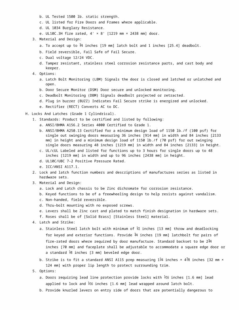
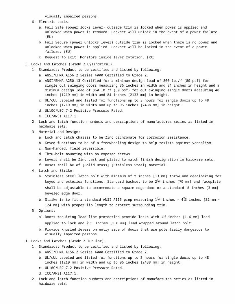
2 Deadbolt function numbers and descriptions of manufactures series as listed in hardware sets3 Material and Design
a Latch bolt 1 inches throw material brass with concealed harden steel roller to prevent sawing or cuttingb Freewheeling collar design to help resists against vandalismc Non-handed field reversible
4 Standardsenspmanufacturer to be certified by the followinga Auxiliary LocksenspANSIBHMA A1565 Grade 1b ULcUL listed for functions up to 3 hours for inchesA inches labelc UL10CUBC 7-2 Positive Pressure Rated
5 Deadbolt function numbers and descriptions of manufactures series as listed in hardware sets6 Material and Design
a Latch bolt 1 inches [254 mm] throw material brass with concealed harden steel roller to prevent sawing or cutting b Freewheeling collar design to help resists against vandalismc Non-handed field reversibled Deadbolts to be 13frasl4 inches [44 mm] total length with a minimum of a 1 inches [254 mm] throw and 3frasl4 inches [19
mm] internal engagement when fully extended and made of Stainless Steel material
OemspMortise Deadbolts1 Standardsenspmanufacturer to be certified by the following
a ANSIBHMA A15613 Series 2000 Grade 1 Operational and Securityb ULcUL listed for functions up to 3 hours for inchesA inches labelc UL10CUBC 7-2 Positive Pressure Rated d ADAmdashThumbturn
2 Deadbolt function numbers and descriptions of manufactures series as listed in hardware sets3 Material and Design
a Latch bolt projection 1 inches [254 mm] throwb Case steel zinc dichromatec Armor front 59frasl16 inches [141 mm] case dimension 45frasl16 inches times 39frasl16 inches times 1 inches [110 mm times 91 mm times 254
mm]
PemspMagnetic Locks1 Standardsenspmanufacturer shall meet requirements forensp
a ANSIBHMA A15623 Grade 1 Compliant2 Designensp
a Epoxy free field upgradeable and repairableb Interlocking mounting plate to secure wiring and mounting screwsc 1200 pounds (544 kg) holding forced Surfaces plated and anodized
3 Optionsenspa Built-in field adjustable 0ndash30 seconds re-lock delay (TIME)b Indicates door open and door closed (DPS)c Indicates locked and unlocked low holding power tampering and obstruction between armature and magnetic
core (MBS)d Indicates access cover removed SPDT dry 1 amp 30 VDCe Door coordinator mounting kit (DC-1)f Spacer bracket for concrete filled and blade stop applications (UF11V)
QemspIntegrated Delayed Egress Lock1 Standardsenspmanufacturer shall meet requirements forensp
a IBCb NFPA 101c CBCd Chicago Building Code
2 Designenspa Field selectable voice message and alarm tone message selectable security or safetyb Provide visual display countdown indicates lock release and verifies if door was opened for egressc 1650pounds (748 kg) holding force
d Field selectable activation1) Door movement2) Exit device with switch kit3) Exit sense bar for non-latching doors
e Field selectable automatic or manual relock upon power up after emergency release or power lossf Integrated three position key switch provides
1) Lock and alarm reset2) Manual power up3) Sustained bypass or timed bypass adjustable for 1 5 20 or 30 seconds
g Field selectable prop alarmh Anti-tailgate featurei Single or multi-door zone control and reset capability
3 Optionsenspa Custom message language or shortened exit delay timesb Magnetic bond sensor output (MBS)c Door status sensor output (DPS)d Anti-tamper sensor output (ATS)
RemspMagnetic Shear Lock1 Design
a 2700 pounds (1225 kg) holding forceb Door static sensor ensures door is at rest and aligned before magnet is energizedc Electronic circuitry incorporates door static positioning timed re-lock sensor and voltage sensord Noise dampers to reduce noise associated with locking and unlocking
2 Optionsenspa Bond sensor indicates proper armature contact (MBS)b Indicates door open and door closed (DPS)c Herculite top rail armature adjustment bracket for leading edge adjustments (HTR)
SemspExit Devices (Grade 1)1 Shall be touch pad type finish to match balance of door hardware2 Standardsenspmanufacturer to be certified and or listed by the following
a BHMA Certified ANSI A1563 Grade 1b ULcUL Listed for up to 3 hours for inchesA inches labeled doorsc UL10CUBC 7-2 Positive Pressure Ratedd UL10B Neutral Pressure Ratede UL 305Listed for Panic Hardwaref 2007 Florida Building Code Certification NumberenspFL94811ANSIBHMA A25013 Severe Windstorm Resistant
Component3 Material and Design
a Touch pad shall extend a minimum of one half-door width Freewheeling lever design shall match design of locks levers Exit device to mount flush with door
b Latchbolts1) Rim devicemdash3frasl4 inches [19 mm] throw Pullman type with automatic dead-latching stainless steel
2) Surface vertical rod devicemdashtop 1frasl2 inches [13 mm] throw Pullman-type with automatic dead-latching stainless steel Bottom 1frasl2 inches [19 mm] throw Pullman-type held retracted during door swing stainless steel Fastenersenspwood screws machine screws and thru-bolts
4 Lock and Latch FunctionsenspFunction numbers and descriptions of manufacturerrsquos series and lever styles indicated in door hardware sets
5 Electric Modificationsa Electric Latch RetractionenspContinuous duty solenoids retract the latch bolt for momentary or maintained periods of
timeb Provide Request to Exit (REX) switches as scheduledc Electrified TrimenspOutside trim locked (EL) or unlocked (EU) by electric current d Delayed Egress with Wall Mounted Controller (4501 DE)
TemspNon-Latching Pressure Sense Push Bar
1 Designa No moving partsb Tri-Failsafe third redundant switch is automatically activated to release door if both sensors or electronics failc Minimum projection from door 17frasl8 inches [48 mm]
d Two dry contact for lock release request to exit alarm or CCTVe Activation force 5 pounds (2 kg) field adjustable to 15 pounds (7 kg)
UemspCylinders And Keying1 Standardsenspmanufacturer shall meet the following
a Auxiliary LocksenspANSIBHMA A1565 b DHI Handbook inchesKeying systems and nomenclature inches
2 Cylindersa Manufacturerrsquos standard tumbler type six pin or seven-pin IC core b Shall be furnished with camstailpieces as required for locking device that is being furnished for project
3 Keyinga Copy of Owners approved keying schedule shall be submitted to Owner and Architect with documentation of which
keying conference was held and Owners sign-offb Provide a bitting list to Owner of combinations as established and expand to twenty five percent for future use or
as directed by Ownerc Key into Ownerrsquos existing keying system if applicabled Keys to be shipped to Ownerrsquos representative individually tag per keying conferencee Provide visual key control identification on keysf Provide interchangeable cores with construction cores as required per hardware schedule
VemspPushPull Plates And Bars1 Standardsenspmanufacturer to be certified by the following
a Architectural Door TrimenspANSIBHMA A1566b Americans with Disabilities Act Accessibility Guidelines (ADAAG)
2 Push platesensp050 inches [13 mm] thick square corner and beveled edges with counter sunk screw holes Width and height as stated in hardware sets
3 Pull platesensp050 inches [13 mm] thick square corner and beveled edges Width and height as stated in hardware sets 3frasl4 inches [19 mm] diameter pull with clearance of 21frasl2 inches [64 mm] from face of door
4 Push Pull Bar Setsensp1 inches [254 mm] round bar stock with 21frasl2 inches [64 mm] clearances from face of door Offset to be 3 inch [76 mm] 90 degree standard Center to center size should be door width less 1 stile width
WemspClosers (Cast Iron Body Grade 1)1 Standardsenspmanufacturer to be certified and or listed by the following
a BHMA Certified ANSI A1564 Grade 1b ADA Compliant ANSI A1171c ULcUL Listed up to 3 hoursd UL10C Positive Pressure Ratede UL10B Neutral Pressure Rated
2 Material and Designa Provide cast iron non-handed bodies with full plastic coversb Closers shall have separate staked adjustable valve screws for latch speed sweep speed and backcheck c Provide Tri-Pack arms and brackets for regular arm top jamb and parallel arm mountingd One-piece seamless steel spring tube sealed in hydraulic fluide Double heat-treated steel tempered springsf Precision-machined heat-treated steel pistong Triple heat-treated steel spindleh Full rack and pinion operation
3 Mountinga Out swing doors shall have surface parallel arm mount closers except where noted on hardware scheduleb In swing doors shall have surface regular arm mount closers except where noted on hardware schedulec Provide brackets and shoe supports for aluminum doors and frames to mount fifth screwd Furnish drop plates where top rail conditions on door do not allow for mounting of closer and where backside of
closer is exposed through glass
4 Size closers in compliance with requirements for accessibility (ADDAG) Comply with following maximum opening force requirementsa Interior hinged openingsensp50 pounds (2 kg)b Fire rated and exterior openings shall have minimum opening force allowable by authority having jurisdiction
5 FastenersenspProvide self-reaming and self-tapping wood and machine screws and sex nuts and bolts for each closer
XemspClosers (Aluminum Body Grade 1)1 Standardsenspmanufacturer to be certified by the following
a BHMA Certified ANSI A1564 Grade 1b ADA Complaint ANSI A1171c ULcUL Listed up to 3 hoursd UL10C Positive Pressure Ratede UL10B Neutral Pressure Rated
2 Material and Designa Provide aluminum non-handed bodies with full plastic covers b Closer shall have separate staked adjustable valve screws for latch speed sweep speed and backcheck c Provide Tri-Pack arms and brackets for regular arm top jamb and parallel arm mountingd Double heat-treated steel tempered springse Precision machined heat-treated steel pistonf Triple heat-treated steel spindleg Full rack and pinion operation
3 Mountinga Out swing doors shall have surface parallel arm mount closers except where noted on hardware scheduleb In swing doors shall have surface regular arm mount closers except where noted on hardware schedulec Provide brackets and shoe supports for aluminum doors and frames to mount fifth screwd Furnish drop plates where top rail conditions on door do not allow for mounting of closer and where backside of
closer is exposed through glass4 Size closers in compliance with requirements for accessibility (ADDAG) Comply with following maximum opening force
requirementsa Interior hinged openingsensp50 pounds (2 kg)b Fire rated and exterior openings shall have minimum opening force allowable by authority having jurisdiction
5 FastenersenspProvide self-drilling and tapping wood screws machine screws and sex nuts and bolts for each closer
YemspClosers (Aluminum Body Grade 2)a BHMA Certified ANSI A1564 Grade 2b ULcUL Listed up to 3 hoursc UL10C Positive Pressure Ratedd UL10B Neutral Pressure Rated
1 Material and Designa Provide aluminum non-handed bodies with pinion cap cover b Closer shall have separate staked adjustable valve screws for latch speed sweep speed adjustable backcheck
valve optional c Provide Tri-Pack arms and brackets for regular arm top jamb and parallel arm mountingd Double heat-treated steel tempered springse Precision machined heat-treated steel pistonf Triple heat-treated steel spindle
2 MountingenspOut swing doors shall have surface parallel arm mount closers except where noted on hardware schedulea In swing doors shall have surface regular arm mount closers except where noted on hardware scheduleb Provide brackets and shoe supports for aluminum doors and frames to mount fifth screwc Furnish drop plates where top rail conditions on door do not allow for mounting of closer and where backside of
closer is exposed through glass3 Size closers in compliance with requirements for accessibility (ADDAG) Comply with following maximum opening force
requirementsa Interior hinged openingsensp50 pounds (2 kg)b Fire rated and exterior openings shall have minimum opening force allowable by authority having jurisdiction
4 Fastenersenspprovide self-reaming and tapping wood and machine screws and sex nuts and bolts for each closer
ZemspProtective Trim
1 Size of protection plateenspsingle doors size two inches less door width (LDW) on push side of door and one inch less on pull side of door For pairs of doors size one inch less door width (LDW) on push side of door and 1frasl2 inches [13 mm] on pull side of doora Kickplates 10 inches [254 mm] high or sized to door bottom rail heightb Mop Plates 4 inches [101 mm] highc Armor Plates 36 inches [914 mm] high
2 Standardsenspmanufacturer shall meet requirements fora Architectural Door TrimenspANSIBHMA A1566b ULULC listed
3 Material and Designa 0050 inches gage stainless steelb Corners shall be square Polishing lines or dominant direction of surface pattern shall run across the door width of
platec Bevel top bottom and sides uniformly leaving no sharp edges Edges shall be de-burredd Countersink holes for screws Screws holes shall be spaced equidistant eight inches CTC along a centerline not
over 1frasl2 inches [13 mm] in from edge around plate End screws shall be a maximum of 053 inches [13 mm] from corners
4 UL label stamp required on protection plates when top of plate is more than 16 inches above bottom of door on fire rated openings Verify door manufactures UL listing for maximum height and width of protection plate to be used
AAemspStops And Holders1 Wall Stopsenspprovide door stops wherever necessary to prevent door or hardware from striking an adjacent partition or
obstruction Provide wall stops when possible Door stops and holders mounted in concrete floor or masonry walls shall have stainless steel machine screws and lead expansion shields
2 Standardsenspmanufacturer shall meet requirements fora Auxiliary hardwareenspANSIBHMA A15616
3 Overhead Stops and Holdersenspprovide overhead stop and holders for doors that open against equipment casework sidelights and other objects that would make wall stopsholders and floor stopsholders inappropriate Provide sex bolt attachments for mineral core wood door applications
4 Standardsenspmanufacturer shall be certified by the followinga Overhead Stops and HoldersenspANSIBHMA A1568 Grade 1
ABemspElectromagnetic Holders1 Standardsenspmanufacturer shall meet requirements forensp
a ANSI 15615 Grade 1b ULULC listed c California State Fire Marshall listed (CSFM)d City of New York MEA approved
2 Material and Designa Provide electromagnetic holders where self-closing fire doors and smoke barrier doors are required to be held
open Electromagnetic holders to be fail safe when electrical current is interrupted doors release to close automatically Holding force shall be 25ndash40 pounds
ACemspProximityPin Reader1 Provide access up to 650 card users and shall be a HID compatible proximity reader 2 Material and Designensp
a Weather resistance two-piece enclosure stand alone access control reader b Access mode selectable proximity card only proximity card plus pin number or key in card number onlyc Key pad programmable does not need software or computerd Key pad lockout and flashing red LED activated when wrong password is entered more than five timese Lock and alarm outputs relays programmable 1ndash99 seconds or on-off latching
3 Optionsenspa HID ProxCards II 25 ea cards 2-679-0021b HID Proxcards II 100 ea cards 2-679-0022c HID ProxKey II 10 ea key fobs 2-679-0023d HID ProxKey II 100 ea key fobs 2-679-0024
ADemspKeypads1 Stand alone digital keypad control access of single entry point with up to 500 users
2 Material and Designenspa 1ndash6 digit PIN codes with 4 outputs 2 relays and solid status outputs timed or latching (onoff)b LED statusenspaccess lockoutc Tactile audible key press with selectable volumed Timed anti-pass back with keypad tamper lockoute Choice of door senserelay inhibit input functions
1) Forced EntryDoor prop alarm2) Door ajar3) Inhibit relay 1 or 24) Auto re-locks when door closes
f Choice of 2 solid status output functions1) Alarm shunt2) Forced entry3) Door ajar4) Tamper lockout5) Keypad active
AEemspKey Switches1 Material and Designensp
a Single gang wall mounted recessed mortise cylinderb Tamper resistance spanner screwsc 20 gauge stainless steel faceplate
2 Functionsa Momentary (MO)b Timed actuation (1ndash60 seconds)c Alternate action (onoff) (AA)
3 Optionsa Anti-tamper switch (ATS)b One (1) green LED (LEDG)c One (1) red LED (LEDRd One (1) green LED and one (1) red LED (2LED)
AFemspExit Switches1 Design
a 2 inches [51 mm] square button inchesPUSH TO EXIT inches b Single gang wall mounted integrated electronic timer fixed 30 secondsc Momentary SPDT
2 Standardsenspmanufacturer shall meet requirements forenspa IBC 1008134b NFPA 72162c California Fire Code
3 Optionsa One (1) green LED (LEDG)b One (1) red LED (LEDR)c One (1) green LED and one (1) red LED (2LED)
4 Designa 2 inches [51 mm] square blue illuminate button with International Symbol of Access (ISA)b Single gang wall mountedc Momentary SPDT
5 Optionsa One (1) green LED (LEDG)b One (1) red LED (LEDR)c One (1) green LED and one (1) red LED (2LED)
AGemspTouchless Exit Switches1 Design
a No touch wave to exit switch with no moving parts
b Dual LED illuminated sensor indicates statusc Sensing range up to 4 inches [102 mm]d DPDT dry contact
AHemspPiezoelectric Exit Switches1 Design
a Constructed of stainless steel with no moving partsb Bi-color status illumination selectable (Relay OFFenspred green or none) (Relay ONenspred green or none)c Adjustable timer output 1ndash30 secondsd Single gang wall mounted e SPDT dry contact
AIemspPresence Infrared Egress Sensor1 Standardsenspmanufacturer shall meet requirements forensp
a UL Listed 2942 Design
a Unlocks door automatically when persons approaching door are detected b Code compliant Fail Safe mode releases locks when power to PRI sensor is interruptedc 2 SPDT dry contacts
AJemspEmergency Break Glass Door Release1 Designensp
a Remote monitoring with CCTV or alarm activationb Built-in alarm may be used as a local door annunciationc Aluminum rod for striking glass includedd Single gang with 2-SPDT contacts
AKemspPower Transfer1 Standardsenspmanufacturer shall meet requirements forensp
a UL Listed Miscellaneous Fire Door Accessoriesb UL 10C Listed for up to 3 hours on fire rated doors and framesc Classified according to Uniform Building Code (UBC) Standard 7-2 Fire Test of Door Assemblies
2 Designenspa Stainless steel tubular wire transfer and cast housing with steel back boxes to provide weather and tamper
resistance when door is open or closedb Mortise door and frame installationc Two 18 gauge wires 5 amps 1224 VACDC
ALemspPower Supplies (For ELR Exit Devices) 1 Standardsenspmanufacturer shall meet requirements forensp
a UL Listed2 Designensp
a Use with 4500 and 4600 Series Electric Latch Retraction (ELR) exit devicesb Automatic operator interfacec 24VDC and 12VDC constant voltage outputsd Adjustable time delay
AMemspPower Supply (For Fail Safe Or Fail Secure Locking Devices1 Standardsenspmanufacturer shall meet requirements forensp
a UL Listed 2 Designensp
a Interface with building alarm controls card readers keypads and other door controlsb Filtered and regulated 24 VDC constant voltagec 2 AMP load capacityd Over voltageshort circuit protectione Surge protection for locking devicesf Interface relayg Adjustable time delay
ANemspPower Supply (For Electrified Locking devices and automatic door operator)
1 Standardsenspmanufacturer shall meet requirements forenspa UL Listed
2 Designenspa Power and control for openings with electrified locking device and automatic door operator b Filtered and regulated 24 VDC constant voltagec Voltage overloadshort circuit protectiond Surge protection for locking devicese Interface relayf Adjustable time delayg Separate inputs for activation switch on entry and egress and ingress side of openingh Relay contact output to automatic operatori Input optional emergency release switchj Auxiliary 24 VDC output and separate 24VDC outputs for Fail SAFE and FAIL SESURE electrified locking devices
AOemspPower Supply (For Modular Access Control)1 Standardsenspmanufacturer shall meet requirements forensp
a UL Listed 2 Designensp
a Use with modular access control systemsb Field selectable filtered and regulated 12 VDC or 24 VDC constant voltagec 1 AMP load capacityd Circuit breaker protected AC input voltage secondary output PTC protectede Fire alarm input provides simultaneous release of Fail Safe locks and holdersf Interface relayg LED status indicators provide information regarding AC input DC output and battery backup statush Separate inputs for activation switch on entry and egress and ingress side of openingi 5 amp hour battery backupj Input 115 VAC (230 VAC optional)k Optional dual 12 VDC or 24 VDC output
APemspDoor Gasketing And Weatherstrip1 Provide continuous weatherstrip gasketing on exterior doors and provide smoke light or sound gasketing where
indicated on hardware schedule Provide non-corrosive fasteners for exterior applicationsa Perimeter gasketingenspApply to head and jamb forming seal between door and frameb Meeting stile gasketingenspFasten to meeting stiles forming seal when doors are in closed positionc Door bottomsenspApply to bottom of door forming seal with threshold or floor when door is in closed positiond Sound GasketingenspCutting or notching for stop mounted hardware not permittede Drip GuardenspApply to exterior face of frame header Lip length to extend 4 inches [102 mm] beyond width of door
2 Standardsenspmanufacturer shall meet requirements fora Door Gasketing and Edge Seal SystemsenspANSIBHMA A15622b 721 is BHMA certified for door sweeps automatic door bottoms and adhesive applied gasketing
3 Smoke-Labeled Gasketingenspcomply with NFPA 105 listed labeled and acceptable to authorities having jurisdiction for smoke control indicateda Provide smoke labeled gasketing on 20 minute rated doors and on smoke rated doors
4 Fire-Rated Gasketingenspcomply with NFPA 80 listed labeled and acceptable to Authorities Having Jurisdiction for fire ratings indicated
5 Refer to Section 08 14 16 Wood Doors for Category A or Category B Comply with UBC 7-2 and UL10C positive pressure where frame applied intumescent seals are required Provide Hager 720 for single and 720 times 724 for a pair of doorsa Perimeter GasketingenspAdhesive Applied 721S720 times 724 Stop Applied 881Sb Sound Seal 864Sc Meeting Stile Weatherstripensp872SNd Door Bottom Sweepsensp750Se Automatic Door Bottomsensp740Sf Overhead Drip Guardensp810S
AQemspThresholds
1 Set thresholds for exterior and acoustical openings in full bed of sealant with lead expansion shields and stainless steel machine screws complying with requirements specified in Division 7 Section inchesJoint Sealants inches Notched in field to fit frame by hardware installer Refer to Drawings for special details
2 Standardsenspmanufacturer to be certified by the followinga ThresholdsenspANSIBHMA A15621b Americans with Disabilities Act Accessibility Guidelines (ADAAG)
ARemspSliding Door Hardware1 Sliding Door Hardwareenspprovide complete sets of rails hangers supports bumpers floor guides and accessories
indicated 2 Standardsenspmanufacturer shall conform to
a Sliding Door HardwareenspANSIBHMA A156143 Bypassing Sliding Door Hardwareensprated for doors weighing up to 150 pounds (68 kg)4 Pocket Sliding Door Hardwareensprated for doors weighing up to 250 pounds (113 kg)
a Provide Pocket door kit for pocket doors Kits are to include header assembly split studs hangers door hanger plates bumper guides floor plate and end bracket
ASemspFolding Door Hardware1 Folding Door HardwareenspProvide complete sets of rails hangers supports bumpers floor guides and accessories
indicated 2 Standardsenspmanufacturer shall conform to
a Folding Door HardwareenspANSIBHMA A156143 Folding Door Hardwareensprated for doors weighing up to 100 pounds (45 kg)
a Provide door hardware for interior bifolding doors when not furnished as part of door package
ATemspDoor Viewer1 Standardsenspmanufacturer shall conform to
a Auxiliary HardwareenspANSIBHMA A15616 for L0332212 Design
a Adjustable for use on doors 13frasl8 inches to 21frasl8 inches [35 mm times 54 mm] thick doors 9frasl16 inches [14 mm] hole required
b One way 200 degree viewc Tamper resistance with a privacy flapd 90 min fire rating
AUemspSilencers1 Where smoke light or weather seal are not required provide three silencers per single door frame two per double
door frame and four per Dutch door frame2 Standardsenspmanufacturer shall meet requirements for
a Auxiliary HardwareenspANSIBHMA A15616
AVemspFinishes1 Appearance of Finished Workenspvariations in appearance of abutting or adjacent pieces are acceptable if within range of
approved Samples Noticeable variations in the same piece are not acceptable Variations in appearance of other components are acceptable if they are within range of approved Samples
2 Comply with base material and finish requirements indicated by ANSIBHMA A15618 designations in hardware schedule
203emspACCESSORIES
AemspKey Cabinets1 Provide key cabinet surface mounted to wall2 Key control system
a Include two sets of key tags hooks labels and envelopesb Contain system in metal cabinet with baked enamel finishc Capacity shall be able to hold actual quantities of keys plus 25 percentd Provide tools instruction sheets and accessories required to complete installation
3 Acceptable manufacturesa Lund Equipmentb Telkey Incorporatedc Key Control
BemspSignage1 Standardsenspmanufacturer shall meet requirements for
a SignageenspANSIBHMA A15616b Grade 2 Braille Translation conforming to section 43 requirements
2 Materials and DesignenspProvide 1frasl4 inches [6 mm] thick plastic Size of sign to be 6 inches times 8 inches [152 mm times 203 mm] fastened with double-sided pressure sensitive tape
3 Acceptable manufacturerenspHager Companiesensp365MW 368U
204emspSOURCE QUALITY CONTROL
AemspElectrified door hardware shall be Listed and Labeled as defined in NFPA 70 Article 100 by a testing agency acceptable to authority having jurisdiction
BemspHardware supplier shall employ an Architectural Hardware Consultant (AHC) as certified by DHI and a member of the seal program who shall be available at reasonable times during course of work for Project hardware consultation1 Electrified Door Hardware Supplier QualificationsenspExperienced door hardware supplier who has completed projects
with electrified door hardware similar in material design and extent to that indicated for this Project whose work has resulted in construction with a record of successful in service performance
CemspDoor hardware shall conform to ICCANSI A1171enspHandles Pulls Latches Locks and operating devicesenspShape that is easy to grasp with one hand and does not require tight grasping tight pinching or twisting of the wrist
DemspFire Rated Door AssembliesenspWhere fire-rated door assemblies are indicated provide door hardware rated for use in assemblies complying with NFPA 80 that are listed and labeled by a qualified testing agency for fire-protection ratings indicated based on testing at positive pressure according to UL 10C unless otherwise indicated
PART 3 EXECUTION
301emspEXAMINATION
AemspVerification of ConditionsenspVerify that conditions of substrates previously installed under other sections or contracts are acceptable for product installation in accordance with manufacturerrsquos instructions prior to [describe product] installation1 Inform [Owner] [Architect] [Consultant] of unacceptable conditions immediately upon discovery2 Proceed with installation only after unacceptable conditions have been remedied [and after receipt of written approval
from [Owner] [Architect] [Consultant]]3 [______]
Specifier NoteenspSpecify actions required to prepare the surface area or site for incorporation of the sectionrsquos primary products Describe requirements for exposure or removal of existing assemblies components products or materials
BemspExamine doors and frames with Installer present for compliance with requirements for installation tolerances labeled fire-rated door assembly construction wall and floor construction and other conditions affecting performance
CemspExamine roughing-in for electrical power systems to verify actual locations of wiring connections before electrified door hardware installation
DemspProceed with installation only after unsatisfactory conditions have been corrected
302emspINSTALLATION
AemspCoordinate installation of [systems] [components] [products] in accordance with [01 73 19 - Installation]
BemspCoordinate [section subject matter] work with work of other trades for proper time and sequence to avoid construction delays
CemspInstall [section subject matter] plumb and level
DemspAccurately fit align securely fasten and install free from distortion or defects
EemspInstall hardware per manufacturerrsquos instructions and in compliance with1 NFPA 802 NFPA 1053 ICCANSI A11714 ANSIBHMA A156115 Hardware Preparation in Steel Doors and Steel Frames5 ANSIBHMA A156115W Hardware Preparation in Wood Doors with Wood or Steel Frames6 DHI PublicationmdashInstallation Guide for Doors and Hardware7 UL10CUBC7-2
FemspDo not install surface mounted items until finishes have been completed on substrates involved Set unit level plumb and
true to line location Adjust and reinforce attachment substrate as necessary for proper installation and operation
303emspFIELD QUALITY CONTROL
Specifier NoteenspSpecify requirements for quality control and related quality assurance for onsite activities and installed materials manufactured units equipment components and accessories
Aemsp[Field] [Site] Tests InspectionenspCoordinate [field] [site] test with Section [01 45 00 - Quality Control]1 [______]
Specifier NoteenspSpecify requirements if manufacturers are to provide field quality control with onsite personnel for instruction or supervision of product installation application erection or construction Manufacturersrsquo field reports are included under PART 1 Submittals
BemspManufacturer Services
Specifier NoteenspUse the following Subparagraphs only when manufacturerrsquos field services are provided and are required to verify the quality of the installed components Establish the number and duration of periodic site visits required by manufacturer and specify below Consult manufacturer for services required Delete if field services are not required
1 Coordinate manufacturerrsquos services with Section [01 45 00 - Quality Control] Have manufacturer review work involved in handling installationapplication protection and cleaning of product[s] and submit written reports in acceptable format to verify compliance of work with Contract
2 Manufacturerrsquos Field ServicesenspProvide manufacturerrsquos field services consisting of product use recommendations and periodic site visits for product installation inspection in accordance with manufacturerrsquos instructions
3 Schedule site visits to review work at stages listeda After delivery and storage of products and when preparatory work on which work of this Section depends is
complete but before installation beginsb [Twice] during progress of work at [25] and [60] completec Upon completion of work after cleaning is carried out
4 Obtain reports within [three] days of review and submit immediately to [Owner] [Architect] [Consultant]
Specifier NoteenspSpecify final actions required to prepare installed products to perform properly Only include the following Article when installation includes control settings or movable parts
CemspFire Door InspectionenspPrior to receiving certificate of occupancy have fire rated doors inspected by an independent certified Fire and Egress Door Assembly Inspector (FDAI) as certified by Intertek (ITS) a written report shall be submitted to Owner and Contractor Doors failing inspection shall be adjusted replaced or modified to be within appropriate code requirements Use for buildings under IBC 2009
304emspADJUSTING
AemspAdjust components and systems for correct function and operation in accordance with manufacturerrsquos written instructions Coordinate with Section [01 75 00 - Starting and Adjusting]
BemspLubricate moving parts to operate smoothly and fit accurately
Cemsp[______]
305emspCLEANING
AemspPerform cleanup in accordance with Section [01 74 00 - Cleaning and Waste Management] and Section [01 74 13 - Progress Cleaning]
BemspUpon completion remove surplus materials rubbish tools and equipment in accordance with Section [01 74 23 - Final Cleaning]
Specifier NoteenspSpecify special measures needed to minimize waste collect recyclable waste and dispose of or recycle field-generated construction waste created during demolition construction or final cleaning
CemspWaste Management1 Coordinate recycling of waste materials with [01 74 19 - Construction Waste Management and Disposal]2 Collect recyclable waste and dispose of or recycle field generated construction waste created during demolition
construction or final cleaning3 Remove recycling containers and bins from site4 [______]
Specifier NoteenspSpecify requirements for demonstrating sequence of operations general facility operation and facility maintenance
procedures and for instructing and training owner on same
306emspPROTECTION
AemspProtect installed product from damage during construction in accordance with Section [01 76 00 - Protecting Installed Construction]
BemspRepair damage to adjacent materials caused by [insert section subject matter] installation
Cemsp[______]
307emspATTACHMENTS
Specifier NoteenspSchedules are sometimes placed in the specifications rather than on the drawings Include schedules that indicate itemelementproductequipment location and other coordinating data
AemspSchedules1 [______]
END OF SECTION
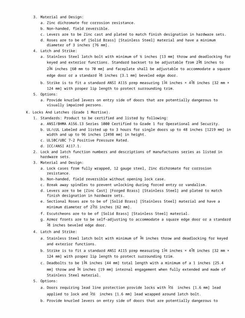
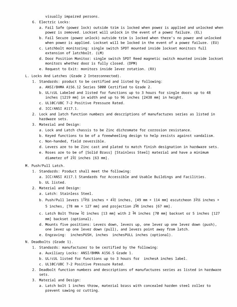