Embed Size (px)
Citation preview

COURSE TITLE: Fundamentals of Control Circuitry
DUTY TITLE: Solid State and Digital Electronics
DUTY NUMBER: 2100
TASK # 32: Solid State and Digital Functions
PURPOSE: To Understand the Concept, Control, and Troubleshooting Techniques of the Various Types of Solid State and Digital Devices.
TASKS:2101 Identify and explain electronic symbols shown on diagrams and schematics.2102 Describe and explain the function of diodes.2103 Explain the function of Zener diodes.2104 Explain the function of transistors.2105 Explain the function of power supplies.2106 Explain the function of filters.2107 Explain the function of half-wave, full wave and three-phase rectifiers.2108 Explain the function of thyristors.2109 Explain the function of single-phase and three-phase inverters.2110 Connect and operate alternating current and direct-current variable speed drives.2111 Troubleshoot alternating current and direct current variable speed drives.
NOTE: This task is not on the current Program of Study Task Listing; however this is an important task the students must learn for the Electrical trade. The P.O.S. numbers shown are from a previous task listing.
REVISION: 2016
1
Schuylkill Technology Center-
South Campus15 Maple Avenue
Marlin, Pennsylvania 17951(570) 544-4748
RESIDENTIAL & INDUSTRIAL ELECTRICITY
Level 3
NAME:
DATE:
DATE DUE:

ENGLISH LANGUAGE ARTSCC.1.2.11-12.J Acquire and use accurately general academic and domain-specific words and phrases, sufficient for reading, writing, speaking, and listening at the college and career readiness level; demonstrate independence in gathering vocabulary knowledge when considering a word or phrase important to comprehension or expressionCC.1.3.11-12.I Determine or clarify the meaning of unknown and multiple-meaning words and phrases based on grade level reading and content, choosing flexibly from a range of strategies and tools.
MATHCC.2.1.HS.F.4 Use units as a way to understand problems and to guide the solution of multi-step problems.CC.2.1.HS.F.6 Extend the knowledge of arithmetic operations and apply to complex numbers.
READING IN SCIENCE & TECHNOLOGYCC.3.5.11-12.B. Determine the central ideas or conclusions of a text; summarize complex concepts, processes, or information presented in a text by paraphrasing them in simpler but still accurate terms.CC.3.5.11-12.C. Follow precisely a complex multistep procedure when carrying out experiments, taking measurements, or performing technical tasks; analyze the specific results based on explanations in the text.
WRITING IN SCIENCE & TECHNOLOGYCC.3.6.11-12.E. Use technology, including the Internet, to produce, publish, and update individual or shared writing products in response to ongoing feedback, including new arguments or information.CC.3.6.11-12.F. Conduct short as well as more sustained research projects to answer a question (including a self generated question) or solve a problem; narrow or broaden the inquiry when appropriate; synthesize multiple sources on the subject, demonstrating understanding of the subject under investigation
2
*CORE CURRICULUM STANDARDS*

*ACADEMIC STANDARDS * READING, WRITING, SPEAKING & LISTENING
1.1.11.A Locate various texts, assigned for independent projects before reading.1.1.11.D Identify strategies that were most effective in learning1.1.11.E Establish a reading vocabulary by using new words1.1.11.F Understanding the meaning of, and apply key vocabulary across the various subject areas1.4.11.D Maintain a written record of activities1.6.11.A Listen to others, ask questions, and take notes
MATH2.2.11.A Develop and use computation concepts2.2.11.B Use estimation for problems that don’t need exact answers2.2.11.C Constructing and applying mathematical models2.2.11.D Describe and explain errors that may occur in estimates 2.2.11.E Recognize that the degree of precision need in calculating2.3.11.A Selecting and using the right units and tools to measure precise measurements2.5.11.A Using appropriate mathematical concepts for multi-step problems2.5.11.B Use symbols, terminology, mathematical rules, Etc.2.5.11.C Presenting mathematical procedures and results
SCIENCE3.1.12.A Apply concepts of systems, subsystems feedback and control to solve complex technological problems3.1.12.B Apply concepts of models as a method predict and understand science and technology3.1.12.C Assess and apply patterns in science and technology3.1.12D Analyze scale as a way of relating concepts and ideas to one another by some measure3.1.12.E Evaluate change in nature, physical systems and man-made systems3.2.12.A Evaluate the nature of scientific and technological knowledge3.2.12.B Evaluate experimental information for appropriateness3.2.12.C Apply elements of scientific inquiry to solve multi – step problems3.2.12.D Analyze the technological design process to solve problems3.4.12.A Apply concepts about the structure and properties of matter3.4.12.B Apply energy sources and conversions and their relationship to heat and temperature3.4.12.C Apply the principles of motion and force3.8.12.A Synthesize the interactions and constraints of science3.8.12.B Use of ingenuity and technological resources to solve specific societal needs and improve the quality of life3.8.12.C Evaluate the consequences and impacts of scientific and technological solutions
ECOLOGY STANDARDS4.2.10.A Explain that renewable and non-renewable resources supply energy and material.4.2.10.B Evaluate factors affecting availability of natural resources.4.2.10.C Analyze the use of renewable and non-renewable resources.4.2.12.B Analyze factors affecting the availability of renewable and non-renewable resources.4.3.10.A Describe environmental health issues.4.3.10.B Explain how multiple variables determine the effects of pollution on environmental health, natural processes and human practices.4.3.12.C Analyze the need for a healthy environment.4.8.12.A Explain how technology has influenced the sustainability of natural resources over time.
CAREER & EDUCATION13.1.11.A Relate careers to individual interest, abilities, and aptitudes13.2.11.E Demonstrate in the career acquisition process the essential knowledge needed13.3.11.A Evaluate personal attitudes that support career advancement
ASSESSMENT ANCHORSM11.A.3.1.1 Simplify expressions using the order of operationsM11.A.2.1.3 Use proportional relationships in problem solving settingsM11.A.1.2 Apply any number theory concepts to show relationships between real numbers in problem solving
3
*ACADEMIC STANDARDS*

STUDENTThe student will be able to identify, connect and control the various types of solid state and digital devices used in the electronic field.
TERMINAL PERFORMANCE OBJECTIVEGiven all the electrical tools and materials required, the student will be able to identify, connect and control the various types of solid state and digital devices used in the electronic field.
SAFETY Always wear safety glasses when working in the shop. Always check with the instructor before turning power on. Always use tools in the correct manner. Keep work area clean and free of debris. Never wire a project without the correct wiring diagram. Make sure the tip of the soldering iron/gun is directed towards a safe area.
RELATED INFORMATION1. Attend lecture by instructor.2. Obtain handout.3. Review chapters in textbook.4. Define vocabulary words.5. Complete all questions in this packet.6. Complete all projects in this packet.7. Complete K-W-L Literacy Assignment by Picking an Article From the
“Electrical Contractor” Magazine Located in the Theory Room. You can pick any article you feel is important to the electrical trade.
EQUIPMENT & SUPPLIES
1. Safety glasses 11. Small bread board
2. Soldering iron/gun 12. 9 Volt battery
3. Screw driver 13. Alligator clips
4. Solder 14. L.E.D. (light Emitting Diode)
5. Wire strippers 15. Small D.C. motor
6. Side cutters 16. Full wave bridge rectifier
7. Cable rippers 17. #22 gauge wire
8. Lineman pliers 18. Power supply
9. Needle nose pliers 19. Solder wick
10. Multimeter 20. In line meter
4

VOCABULARY
CC.1.3.11-12.I Determine or clarify the meaning of unknown and multiple-meaning words and phrases based on grade level reading and content, choosing flexibly from a range of strategies and toolCC.3.5.11-12.D. Determine the meaning of symbols, key terms, and other domain-specific words and phrases as they are used in a specific scientific or technical context relevant to grades 11–12 texts and topics.
Semi-Conductor:
Electrolytic:
Diac:
Junction Diode:
Resistor:
Varistor:
Diode:
Potentiometer:
Light Emitting Diode:
Farad:
5

Thermistor:
Transistor:
Zener Diode:
Limit Switch:
Voltaic Pile:
Metal Film Resistor:
S.C.R.
Hall Effect Device:
Carbon Film Resistor:
Hi-Pot:
Digital Device:
6

Limit Switch:
Fixed resistor:
Photosensitive Diode:
Capacitor:
Voltage Regulator:
Primary Cell:
Valence Electrons:
Unit 2Semiconductors
Objectives The student will be able to:– Discuss the atomic structure of conductors, insulators, and semiconductors– Discuss how a P-type material is produced– Discuss how an N-type material is produced Conductors
Conductors are materials with lots of free electrons. The best conductors are metals.– Examples: silver, copper, aluminum
An atom that has only one valence electron makes a great conductor.Conductors & Insulators Insulators are materials with very few free electrons.
7

Atoms with full valence shells make good insulators. Examples of good insulators:– Rubber, glass, wood, plastic, paper
Semiconductors Semiconductors are neither good conductors nor good insulators. Semiconductor materials have four valence electrons in their outer orbit. Germanium and silicon are the most common semiconductor materials. A substance with four valence electrons must be mixed with an impurity, such as indium or gallium, to make it a semiconductor.– Process is known as doping When a semiconductor material has a net positive charge, it is called a P-type material. When a semiconductor material has a net negative charge, it is called an N-type material. All solid-state devices are made up of P-type and N-type material. A diode is the simplest solid-state device. It is made by joining a P-type material with an N-type material to form a PN junction.Summary In this unit, we:– Discussed the atomic structure of conductors, insulators, and semiconductors– Examined how P-type and N-type semiconductor materials are produced
Unit 4The Zener Diode
Objectives The student will be able to:– Explain the difference between a junction diode and a zener diode.– Discuss common applications of a zener diode.– Connect a zener diode in a circuit.A Special Diode A zener diode is designed to be operated with reverse polarity. It is designed to operate safely in the zener region. In the zener region, the voltage drop across the zener diode is constant. Any device connected in parallel with the zener diode will have a constant voltage.
Voltage Drop In a zener circuit, the supply voltage must be greater than the zener voltage.– The load circuit is connected in parallel with the zener diode.
8

– Thus the voltage across the load is the same as the voltage of the zener diode.– A constant 12 volts will remain across the load.Voltage Regulator A zener diode makes a great voltage regulator.– Even if current through the load changes, the voltage across the load will remain constant.– Here is the schematic symbol for a zener diode.Summary In this unit, we:– Examined the difference between a junction diode and a zener diode– Discussed the application of a zener diode as a voltage regulator– Saw how the diode is connected in a circuit
Unit 5The Transistor
Objectives The student will be able to:– Discuss the difference between PNP and NPN Transistors– Test transistors with an ohmmeter.– Identify the leads of standard, case-style transistors– Discuss the operation of a transistor– Connect a transistor in a circuitTransistor Construction Transistors are made with three pieces of semiconductor material. Common transistors are either NPN or PNP. An NPN transistor has a positive voltage on its collector and a negative voltage on its emitter. The base is positive. A PNP transistor has a negative voltage on its collector and a positive voltage on its emitter. The base is negative.
9

Testing a Transistor with an Ohmmeter A transistor being tested with an ohmmeter will appear as back-to-back diodes. If the ohmmeter lead polarity is known, the transistor can be identified as NPN or PNP. An NPN transistor “looks” to an ohmmeter as though its two diodes have their anodes connected. A PNP transistor “looks” to an ohmmeter as though its two diodes have their cathodes connected together.Transistor Operation A transistor operates as an electric valve. A large current flows from collector to emitter when a small current flows through the base-emitter. Thus, with a transistor, a small current controls a much larger current.Transistor Applications A transistor can be operated as a digital or an analog device. As a digital device it is a fast-acting switch. Current either flows or it does not. There are only two states: on or off. As an analog device, it uses a small voltage to control a much larger one. Current can vary from zero to maximum. As an analog device, the transistor amplifies a weak incoming signal.Transistor Case Styles Transistor case styles are identified with a “TO” marking, meaning “transistor outline.” Various transistor packages are shown in the figures in the following slide.Summary In this unit, we:– Discussed the differences between NPN and PNP transistors– How to test a transistor with an ohmmeter– How to identify transistor lead configurations– Saw how a transistor operates as a digital or analog device– Examined how a transistor is connected in a circuit
Unit 7The SCR
Objectives The student will be able to:– Discuss the operation of an SCR in a DC circuit– Discuss the operation of an SCR in an AC circuit– Draw the schematic symbol for an SCR– Discuss phase shifting– Test an SCR with an ohmmeter– Connect an SCR in a circuit
10

The Multi-Layered SCR A silicon-controlled rectifier (SCR) is made up of four layers of semiconductor material. The schematic symbol for an SCR is similar to that for a diode, with the addition of gate lead.The SCR as a Controlling Device The SCR is a digital on-off device that is often used to control large amounts of power. When off, the SCR drops the full supply voltage but conducts no current. Therefore, its power dissipation is zero. When on, the SCR drops only a volt. Thus, current is limited by the load resistor.
The SCR in a DC Circuit An SCR can be thought of as a solid-state latching switch. When the SCR’s anode is positive and its cathode is negative, the SCR is in its “ready” state. It is capable of conducting current.The SCR in a DC Circuit When the SCR’s gate receives a positive charge, even for only a short period of time, the SCR will conduct current between its cathode and anode. Though the SCR has now latched on, its gate has lost control of the SCR. When the SCR’s current is reduced below the holding current value, the SCR will turn off. Turning an SCR off is usually accomplished by opening a switch in the cathode or anode circuit.The SCR in an AC Circuit The output of an SCR in an AC circuit is direct current. When the AC waveform drops to zero at the end of each half cycle, the SCR turns off. The gate must retrigger the SCR for each conduction cycle.Phase Shifting the SCR With phase shifting, the SCR can control all of the positive AC waveform. To phase shift an SCR, the gate circuit must be separated from the anode circuit. With phase shifting, the SCR is fired as early or as late during the positive half cycle as desired.Testing the SCR An SCR can be tested with an ohmmeter. The positive output lead of the meter is connected to the SCR’s anode. The negative output lead of the meter is connected to the SCR’s cathode. If the gate is now touched to the anode of the SCR, the meter will show continuity.Summary In this unit, we:– Discussed SCR operation in DC and AC circuits– Examined the SCR schematic symbol– Discussed SCR phase shifting
11

– Saw how to test an SCR with an ohmmeter– Examined an SCR in a circuit
Unit 8The Diac
Objectives The student will be able to:– Draw the schematic symbol for a diac– Discuss the operation of a diac– Connect a diac in a circuitDiac Function The diac is a special-purpose, bidirectional diode. Diac operation is similar to that of a UJT. A diac is a two-directional device. The diac, unlike a UJT, can operate in an AC circuit. The diac is used to phase shift a triac.A Voltage Sensitive Switch Voltage applied to a diac must reach a predetermined level before it will activate. When a diac fires, it displays a negative resistance. A diac will conduct at a lower voltage than the voltage needed to turn it on. The diac schematic symbol shows back to back diodes.
A Voltage Sensitive Switch The diac is a voltage sensitive AC switch.Summary In this unit, we:– Examined the diac schematic symbol– Discussed diac operation– Saw it connected in an AC circuit
Unit 16The Solid-State Relay
Objectives The student will be able to:– Discuss the difference between DC solid-state relays and AC solid-state relays– Discuss opto-isolation– Discuss magnetic isolation– Connect a solid-state relay in a circuit.Solid-State Relay Basics The solid-state relay is an all electronic device with no moving parts.
12

The key advantage of a solid-state relay is that the control input voltage is isolated from the line device the relay is intended to control.DC and AC Control Solid-state relays can be used to control both DC and AC loads. In DC circuits an opto-isolator with a power transistor is often used. The load side of the relay is optically isolated from the control side of the relay. With opto-isolation, no voltage spikes or electrical noise produced on the load side of the relay can be transmitted to the control side of the relay. Solid-state relays used in AC control use a triac instead of a power transistor on the load side. An LED and photo detector make the “connection” between the control circuit and the load circuit.Other Control Methods Some solid-state relays use a small reed-relay to control the output. A magnetic field built up around the coil causes the reed contacts to attract and close. Here a magnetic field, rather than a light beam, is used for isolation.Control Voltages Control voltages range from 3 to 32 volts. Control voltages can be DC or AC. If a triac is used, load voltage ratings of from 120 to 240 volts AC are common. With a triac, current ratings range from 5 to 25 amps.Zero Switching Many solid-state relays have a zero switching feature. With zero switching, if the relay is “told” to turn off when the AC voltage is in the middle of a cycle, it will continue to conduct until the AC voltage drops to a zero level, and will then turn off.Packaging Solid-state relays are available in many different case styles and power ratings. One of the most common uses of a solid-state relay is in the I/O track of a programmable logic controller.Summary In this unit, we:– Discussed the difference between DC and AC solid state relays– Examined opto-isolation– Discussed magnetic isolation– Saw how a solid-state relay is connected in a circuit
Unit 21Limit Switches
Objectives The student will be able to:– Explain the use of limit switches in the automatic operation of machines and machine tools
13

– Wire a simple two-wire circuit using a limit switch– Read and draw normally open (NO) and normally closed (NC) wiring symbolsLimit Switch Basics Limit switches are activated by the motion of machinery or a process. The limit switch must have high repeat accuracy, be reliable, and have an instantaneous response. When installing limit switches, one must consider size, operation force, stroke, and manner of mounting. Limit switches may be used either as control devices for regular operation or as emergency switches to prevent improper functioning of machinery. Limit switches may be momentary-contact or maintained-contact types.Micro Limit Switches Micro limit switches are much smaller than normal limit switches. With such a switch, only a small amount of travel is required to cause the contacts to close.Subminiature Micro Switches These switches operate in a similar manner to the micro switch, yet they are even smaller: approximately one-half to one-fourth the size of the basic switch. Such switches have contact ratings at from about 1 ampere to 7 amperes.Summary In this unit, we:– Examined the use of the limit switch– Studied the schematic symbol for the limit switch.
Unit 25Hall Effect Sensors
Objectives The student will be able to:– Describe the Hall effect– Discuss the principles of operation of a Hall generator– Discuss applications in which Hall generators can be usedPrinciples of Operation With a Hall Effect generator, a constant current power supply is connected to opposite sides of a piece of semiconductor material. A sensitive voltmeter is connected to the other two sides. If current flows straight through the semiconductor, no voltage is developed across the voltmeter. If a magnetic field is brought near the semiconductor material, the current will be deflected to one side, causing a voltage to appear across the other sides. Two factors determine the polarity of the voltage produced by the generator:– The direction of current flow through the semiconductor material– The polarity of the magnetic field used to deflect the current Two factors determine the amount of voltage produced by the generator:
14
– The amount of current flowing through the semiconductor material– The strength of the magnetic field used to deflect the current path The Hall generator has many advantages:– it is solid-state– it is not affected by dirt, oil, or vibrations– it comes in a convenient integrated circuit packageMotor Speed Sensor A Hall generator can be used to measure the speed of a rotating device, with a magnet mounted on a disc and a Hall sensor placed nearby. The frequency of the AC output is proportional to the number of magnetic poles on the disc and the speed of rotation. Another approach to measuring speed rotation is to use a reluctor, a ferrous metal disk used to shunt a magnetic field away from some other object. When the notch is between the sensor and the magnet, a voltage is produced. When the metal is between the sensor and the magnet, a drop in voltage occurs.
Position Sensor As a position sensor, a Hall generator operates as a digital device that senses the presence or absence of a magnetic field. In the following figure, we see a Hall generator acting as a limit switch. Such a sensor has no contact wear; it can be used over and over again, millions of times.
Hall Effect Limit Switches The type of limit switch shown at right uses a Hall generator instead of a set of contacts. Such switches are operated on DC voltages from 5 to 24 volts.Current Sensors If a Hall sensor is mounted near a coil of wire, a voltage will be produced by the generator when current flows through the wire. The generator can operate at pulse rates as high as 100,000 pulses per second.Linear Transducers A linear transducer is designed to produce an output voltage that is proportional to the strength of a magnetic field. A Hall effect linear transducer can be obtained that has two types of outputs:– A regulated output that produces voltages from 1.5 to 4.5 volts– A ratio metric output that produces an output voltage which is 25% to 75% of the input voltage
Unit 5Resistors
15

Objectives:• List the major types of fixed resistors.• Determine the resistance of a resistor using the color code.• Discuss how exceeding its power rating can cause damage to a resistor.• Discuss the use of a variable resistor as a potentiometer.
Resistors are commonly used to perform two functions in a circuit.The first use is to limit the flow of current in a circuit.
Resistors are commonly used to perform two functions in a circuit.The second use is to produce a voltage divider.
Fixed resistors have only one ohmic value, which cannot be changed or adjusted. One type of fixed resistor is the composition carbon resistor.
Carbon resistors are very popular for most applications because they are inexpensive and readily available in standard sizes and wattages.
Metal film resistors are another type of fixed resistor. These resistors are superior to carbon resistors because their ohmic value does not change with age and they have improved tolerance.
Wire-wound resistors are fixed resistors that are made by winding a piece of resistive wire around a ceramic core. These are used when a high power rating is required.
The resistor color code can be used to determine the resistor’s ohmic value and tolerance.
Exceeding the power rating causes damage to a resistor.Variable resistors can change their value over a specific range. A potentiometer is a variable resistor with three terminals. A rheostat has only two terminals.
Schematic symbols are used to represent various types of fixed resistors.Review:• Resistors are used in two main applications: as voltage dividers and to limit the flow of current in a circuit.• The value of fixed resistors cannot be changed.• There are several types of fixed resistors such as composition carbon, metal film, and wire-wound.• Carbon resistors change their resistance with age or if overheated.• Metal film resistors never change their value, but are more expensive than carbon resistors.• The advantage of wire-wound resistors is their high power ratings.
16

• Resistors often have bands of color to indicate their resistance value and tolerance.• Resistors are produced in standard values. The number of values between 0 and 100 Ω is determined by the tolerance.• Variable resistors can change their value within the limit of their full value. A potentiometer is a variable resistor used as a voltage divider.
UNIT 12Batteries and Other Sources of Electricity
KEY TERMSBattery Nickel-cadmium (nicad) cellPiezoelectricity CellPrimary cell Current capacitySecondary cell Electro-motive series of metalsSpecific gravity HydrometerThermocouple Internal resistanceVoltaic cell Voltaic pileLoad testHistory of the BatteryBriefly go over the history of the battery. Ask students to explain why the saline solution on the frog caused the frog to become a conductor of electricity.CellsExplain what a voltaic cell is and describe how easily one can be constructed. If you have the potato, the voltmeter, and the wires needed, hook up this cell for students to see. Explain that the voltage produced is quite small. After describing the cell created in Figure 12-3, ask students if they have ever licked the top of a 9-volt battery to see if itwas still good. Then, ask them if they now understand why they received a slight shock on the tongue (acid or alkali in their saliva acting as an electrolyte).Cell Voltage
17
Explain that the type of materials used to make a cell is what determines its voltage. Refer students to the charts of metals in Figure 12-5 and Figure 12-6. Explain the difference between a primary cell and a secondary cell.Primary CellsDiscuss the process taking place between the zinc and copper suspended in the conductive solution. Have students explain to you what is taking place.
The Carbon-Zinc CellDiscuss the process Leclanché came up with. Have students explain why this combination of materials worked. Be sure they know what a dry cell battery is.Alkaline CellsDescribe alkaline cells and compare them to carbon-zinc cells. Discuss the advantages and disadvantages of alkaline cells.Button CellsDiscuss various types and have students give examples of items that they use button cells in. Explain the differences between mercury-zinc button cells and silver-zinc button cells. Refer students to Figure 12-13 for an excellent view of each part of the mercury button cell.Lithium CellsDescribe the various types of lithium cells. Discuss why different types of cathode materials can be used, as well as different types of electrolyte substances. Be sure students make note of the shelf life of those using a solid electrolyte. Ask students why that might be important.Current Capacity and Cell RatingsHave students write the definition of current capacity into their notes, as well as the statement that the amount of current a particular type of cell can deliver is determined by the surface area of its plates. Hold up a size D cell next to a size AA or AAA cell to illustrate the point.Discuss the factors necessary to determine a cell’s current capacity. Explain what the milliampere (mA) is, and how it applies to rating primary cells. Go through the process of figuring watt-hours, and watt-hours per cubic inch.Internal ResistanceDiscuss that all cells have internal resistance and how this is affected as the cell is used and ages. Have students explain to you what this means in terms of real milliamperes delivered over a period of time.
12-5 Secondary Cells: Lead-Acid BatteriesExplain what a secondary cell is and ask students for examples. Define specific gravity and explain what a hydrometer is.Discharge CycleDiscuss this cycle and have students explain how the hydrometer can be used to check for the level of charge left in the battery.Charging CycleExplain this process and have students give examples of ways this can be done. Also, ask students why they think people are always warned not to smoke around a battery being charged.
18

Cautions Concerning ChargingIn addition to the warning about smoking around a charging battery, be sure students are aware of the other hazards involved with overcharging a battery.Sealed Lead-Acid BatteriesDescribe these types of batteries, referring students to Figure 12-24. Ask students why these types of batteries can be more advantageous than those using a liquid electrolyte.Ratings for Lead-Acid BatteriesDiscuss ampere-hour ratings and how the rating is determined. Also discuss cold cranking amperes for automotive batteries.Testing Lead-Acid BatteriesExplain the load test and why it might need to be used when the hydrometer reading cannot be trusted. Discuss how the test is conducted and what voltage level should be maintained for the specified amount of time.12-6 Other Secondary CellsNickel-Iron Batteries (Edison Battery)Describe these cells and discuss their advantages and disadvantages. Discuss in what circumstances they would be more useful than a lead-acid cell.
Nickel-Cadium BatteriesDescribe these cells and discuss their advantages and disadvantages. Explain the discharge-recharge memory factor of this cell. Ask students if they have used any cells like this (most camcorder batteries are this type of rechargeable battery with a memory curve).
12-7 Series and Parallel Battery ConnectionsExplain the effect of connecting batteries or cells in series. Make sure students understand that the voltages add, while the current capacities remain the same. Refer students to Figures 12-28 through 12-30. Emphasize that batteries of different voltages should never be connected in parallel. Go over how batteries can also be connected in a series parallel combination.12-8 Other Small Sources of ElectricitySolar CellsExplain what solar cells are and how P-type material and N-type material are formed. Discuss what happens when the photons of light strike the surface of the photo cell. Explain the necessity of creating connections of solar cells in series or parallel or both in order to obtain desired amounts of voltage and current.
19
UNIT 19Capacitors
KEY TERMSCapacitor JAN standard Dielectric Variable capacitorsDielectric constant Surface areaDielectric stress RC time constantElectrolytic Polarized capacitorsElectrostatic charge PlatesExponential Non-polarized capacitorsFarad Leakage current HIPOT
19-1 CapacitorsWhile holding up a capacitor or passing a few around the room, explain what a capacitor is. Be extremely firm when warning students against charging up a capacitor before
20

handing it to someone else. Go over the three things that determine a capacitor’s capacitance, or the electrical size of the capacitor.Explain what a dielectric is, and review the different types of materials that are used as dielectrics.Discuss surface area, and how that affects the capacitor and the movement of the electrons from one plate to another.Be sure students realize that once a capacitor has been charged, it stays charged until a path is introduced for the electrons to travel on. Point out the rule concerning capacitors and current flow.Explain leakage current and how it occurs. Remind students that insulators are materials with seven or eight valence electrons, and are used because they resist the flow of electricity. Explain that a dielectric is a type of insulator, but that no dielectric is a perfect insulator. The result of this is leakage current, and the possibility of the capacitor becoming a leaky capacitor.19-2 Electrostatic ChargeExplain how a capacitor stores energy and differentiate between a capacitor’s stored energy and the stored energy of an inductor.Dielectric StressExplain what dielectric stress is and how it occurs. Refer to Figure 19-7 and Figure 19-8 in the text to illustrate.Describe the potential or stored energy effect that this stress has on the capacitor.Discuss voltage as it relates to shorting out a capacitor and lowering the life span of a capacitor. Show students how to identify the voltage rating of a capacitor, and warn them, again, of the consequences of exceeding that rating.Discuss how the energy of the capacitor is stored in the dielectric as an electrostatic charge. Using the examples from the text of the camera .ash and the 0.357 cartridge, ask students if they understand why a charged capacitor should not be handed to someone. Ask about shocks students may have received after sliding across a car seat and touching the car door. Enlarge that for them, exponentially, to communicate the potential waiting to be released from the capacitor.19-3 Dielectric ConstantExplain how this number is obtained and what it means. Make sure students know that a farad is the basic unit of capacitance.19-4 Capacitor RatingsRemind students of what a coulomb is. Explain that the change of a volt across the plates of a capacitor, resulting in the movement of 1 coulomb, gives the capacitor a capacitance of 1 farad.Go over the chart of various dielectric materials, and the dielectric constant levels of those materials. Remind students that air is always the starting point. Ask students why this is the case, and see if they can relate it back to electrostatic charges.Carefully go through the steps involved in solving for capacitance of a capacitor. Make sure students understand when to plug in microfarads, nano-farads, and pico-farads to make the problem easier to work with19-5 Capacitors Connected in ParallelDiscuss connecting capacitors in parallel and why this is done. Go through the simple procedure used to determine the total capacitance of capacitors set up in parallel.
21

19-6 Capacitors Connected in SeriesDistinguish between capacitors set up in series and capacitors set up in parallel. Make sure students understand that a parallel system adds one capacitor to another, for an overall capacitance larger than any one capacitor in the parallel connection. The capacitors in series, however, are the opposite, reducing the overall capacitance when connected in series. Go over the formula used to solve for capacitance when connected in series.19-7 Capacitive Charge and Discharge RatesMake sure students understand the difference between changing exponentially versus added change. Two examples you can use are hurricanes and earthquakes. Explain that an earthquake registering a 5 on the Richter scale is not 5/6 as strong as an earthquake registering a level 6. Additionally, a category 3 hurricane is not 3/4 as strong as a category 4 hurricane. Make sure students understand the power potential that accumulates under exponential growth.Show students, on the board, how the charging pattern occurs in a capacitor at a level of 63.2% of whatever the required charge is, over and over, until the maximum required charge has been reached. Explain that this is also true in reverse for discharging a capacitor.19-8 RC Time ConstantsExplain how to determine the amount of time needed to charge a capacitor that is connected in a circuit with a resistor. Go through the formula and make sure students can use the formula correctly by giving them a couple of practice problems.
19-9 Applications for CapacitorsProvide actual examples or pictures to show students real life applications. Give a general summary of the various everyday uses of capacitors.19-10 Non-polarized CapacitorsDescribe what a non-polarized capacitor is and what it consists of. Discuss its uses and advantages over polarized capacitors.Explain how oil-filled capacitors are marked, what this indicates, and how students should use this information when connecting the capacitor. Make sure students understand why the way in which the capacitor is connected can either lead to or prevent damage to the item the capacitor is connected to.19-11 Polarized CapacitorsDistinguish between these capacitors and non-polarized capacitors in their uses and limitations of use. Make sure students realize, however, the difference in capacitance available in a smaller polarized capacitor.Discuss both the wet and dry types of electrolytic capacitors, and how they are used.AC Electrolytic CapacitorsExplain the process of shorting out and reforming with this type of wet electrolytic capacitor. Describe when, where, and why this type of capacitor would be needed.Dry-Type Electrolytic CapacitorsDistinguish it from a wet-type capacitor and describe the gauze makeup of this type of capacitor. Ask students why this internal makeup might be advantageous in a capacitor.19-12 Variable Capacitors
22

Compare these capacitors to those with dielectric constants. Explain how the movable plates are used in conjunction with the stationary plates to change the capacitance value.19-13 Capacitor MarkingsAgain, show some capacitors and resistors together. It is important for students to feel comfortable distinguishing between the two. Refer back to Figure 5-9 of the text to compare the different color codes of resistors and capacitors.Discuss the various ways that capacitors are marked, and why these markings vary. Practice on the sample capacitors to see if students can identify the capacitor’s voltage, tolerance, and so on.Review the EIA standard and the JAN standard with students. Make sure students understand the difference, and know to look for the identifying white dot that indicates the EIA standard being used.
19-14 Temperature CoefficientsShow students where to find this marking on a capacitor. Make sure they know what positive and negative temperature coefficient markings mean.19-15 Ceramic CapacitorsIf you have samples of these, pass them around and compare them to the other samples. Point out the wide color band, indicating the temperature coefficient.19-16 Dipped Tantalum CapacitorsProvide samples, if possible, to help identify the different shape of this capacitor. Point out how to use the color bands and dots to determine the various values.19-17 Film CapacitorsDiscuss how these capacitors are different, and how their markings are interpreted.19-18 Testing CapacitorsDiscuss the various ways of testing capacitors. Explain how and why some capacitors need to be tested for both capacitance value and the strength of the dielectric.Review a few testing procedures. Remind students that some capacitors also need to be tested for leakage.Explain how the dielectric strength test is done and why it is necessary.Unit Round UpReview the key terms and go over the summary in class. Have students do the review at home, and then go over it together during your next class. If you have the materials, this would be a great time for the students to gain some hands-on experience. If you do this, warn students, again about the potential energy stored in a capacitor, and why it is not wise (or funny) to give a charged capacitor to anyone.Be sure to have students fill in the RC time constants chart at the end of the review section. You may want to reproduce this on the board and have students come up, one by one, and show how they solved for the missing values.
23

REFERENCE PAGES
24

Electronics
25

Surface mount electronics
Electronics is the study of the flow of charge through various materials and devices such as semiconductors, resistors, inductors, capacitors, nano-structures and vacuum tubes. Although considered to be a theoretical branch of physics, the design and construction of electronic circuits to solve practical problems is an essential technique in the fields of electronic engineering and computer engineering.
The study of new semiconductor devices and surrounding technology is sometimes considered a branch of physics. This article focuses on engineering aspects of electronics.
Overview of electronic systems and circuits
26

Commercial digital voltmeter checking a prototype.
Electronic systems are used to perform a wide variety of tasks. The main uses of electronic circuits are:
1. The controlling and processing of data.
2. The conversion to/from and distribution of electric power.
Both these applications involve the creation and/or detection of electromagnetic fields and electric currents. While electrical energy had been used for some time prior to the late 19th century to transmit data over telegraph and telephone lines, development in electronics grew exponentially after the advent of radio.
One way of looking at an electronic system is to divide it into 3 parts:
Inputs – Electronic or mechanical sensors (or transducers). These devices take signals/information from external sources in the physical world (such as antennas or technology networks) and convert those signals/information into current/voltage or digital (high/low) signals within the system.
Signal processors – These circuits serve to manipulate, interpret and transform inputted signals in order to make them useful for a desired application. Recently, complex signal processing has been accomplished with the use of Digital Signal Processors.
Outputs – Actuators or other devices (such as transducers) that transform current/voltage signals back into useful physical form (e.g., by accomplishing a physical task such as rotating an electric motor).
For example, a television set contains these 3 parts. The television's input transforms a broadcast signal (received by an antenna or fed in through a cable) into a
27

current/voltage signal that can be used by the device. Signal processing circuits inside the television extract information from this signal that dictates brightness, color and sound level. Output devices then convert this information back into physical form. A cathode ray tube transforms electronic signals into a visible image on the screen. Magnet-driven speakers convert signals into audible sound.
Electronic devices and componentsAn electronic component is any physical entity in an electronic system whose intention is to affect the electrons or their associated fields in a desired manner consistent with the intended function of the electronic system. Components are generally intended to be in mutual electromechanical contact, usually by being soldered to a printed circuit board (PCB), to create an electronic circuit with a particular function (for example an amplifier, radio receiver, or oscillator). Components may be packaged singly or in more or less complex groups as integrated circuits.
Types of circuits
Analog circuits
28

Hitachi J100 adjustable frequency drive chassis.Most analog electronic appliances, such as radio receivers, are constructed from combinations of a few types of basic circuits. Analog circuits use a continuous range of voltage as opposed to discrete levels as in digital circuits. The number of different analog circuits so far devised is huge, especially because a 'circuit' can be defined as anything from a single component, to systems containing thousands of components.
Analog circuits are sometimes called linear circuits although many non-linear effects are used in analog circuits such as mixers, modulators, etc. Good examples of analog circuits include vacuum tube and transistor amplifiers, operational amplifiers and oscillators.
Some analog circuitry these days may use digital or even microprocessor techniques to improve upon the basic performance of the circuit. This type of circuit is usually called "mixed signal."
Sometimes it may be difficult to differentiate between analog and digital circuits as they have elements of both linear and non-linear operation. An example is the comparator which takes in a continuous range of voltage but puts out only one of two levels as in a digital circuit. Similarly, an overdriven transistor amplifier can take on the characteristics of a controlled switch having essentially two levels of output.Digital circuits
Digital circuits are electric circuits based on a number of discrete voltage levels. Digital circuits are the most common physical representation of Boolean algebra and are the basis of all digital computers. To most engineers, the terms "digital circuit", "digital system" and "logic" are interchangeable in the context of digital circuits. In most cases the number of different states of a node is two, represented by two voltage levels
29

labeled "Low"(0) and "High"(1). Often "Low" will be near zero volts and "High" will be at a higher level depending on the supply voltage in use.
Computers, electronic clocks, and programmable logic controllers (used to control industrial processes) are constructed of digital circuits. Digital Signal Processors are another example.
Building-blocks:
Logic gates Schmitt triggers
Adders Multiplexers
Binary Multipliers Registers
Flip-Flops Counters
Highly integrated devices:
Microprocessors Field-programmable gate array (FPGA)
Microcontrollers Digital signal processor (DSP)
Application-specific integrated circuit(ASIC)
Mixed-signal circuitsMixed-signal circuits refers to integrated circuits (ICs) which have both analog circuits and digital circuits combined on a single semiconductor die or on the same circuit board. Mixed-signal circuits are becoming increasingly common. Mixed circuits are usually used to control an analog device using digital logic, for example the speed of a motor. Analog to digital converters and digital to analog converters are the primary examples. Other examples are transmission gates and buffers.
Heat dissipation and thermal managementHeat generated by electronic circuitry must be dissipated to prevent immediate failure and improve long term reliability. Techniques for heat dissipation can include heat sinks
30

and fans for air cooling, and other forms of computer cooling such as water cooling. These techniques use convection, conduction, & radiation of heat energy.
NoiseNoise is associated with all electronic circuits. Noise is defined [1] as unwanted disturbances superposed on a useful signal that tend to obscure its information content. Noise is not the same as signal distortion caused by a circuit.
Electronics theoryMathematical methods are integral to the study of electronics. To become proficient in electronics it is also necessary to become proficient in the mathematics of circuit analysis.
Circuit analysis is the study of methods of solving generally linear systems for unknown variables such as the voltage at a certain node or the current though a certain branch of a network. A common analytical tool for this is the SPICE circuit simulator.
Also important to electronics is the study and understanding of electromagnetic field theory.
Electronic test equipmentElectronic test equipment is used to create stimulus signals and capture responses from electronic Devices Under Test (DUTs). In this way, the proper operation of the DUT can be proven or faults in the device can be traced and repaired.
Practical electronics engineering and assembly requires the use of many different kinds of electronic test equipment ranging from the very simple and inexpensive (such as a test light consisting of just a light bulb and a test lead) to extremely complex and sophisticated such as Automatic Test Equipment.
Computer aided designToday's electronics engineers have the ability to design circuits using pre-manufactured building blocks such as power supplies, semiconductors (such as transistors), and integrated circuits. Electronic design automation software programs include schematic capture programs and printed circuit board design programs. Popular names in the EDA software world are NI Multisim, Cadence (ORCAD), Eagle PCB and Schematic, Mentor (PADS PCB and LOGIC Schematic), Altium (Protel), LabCentre Electronics (Proteus) and many others.
Construction methodsMany different methods of connecting components have been used over the years. For instance, early electronics often used point to point wiring with components attached to
31

wooden breadboards to construct circuits. Cordwood construction and wire wraps were other methods used. Most modern day electronics now use printed circuit boards (made of FR4), and highly integrated circuits. Health and environmental concerns associated with electronics assembly have gained increased attention in recent years, especially for products destined to the European Union, with its Restriction of Hazardous Substances Directive (RoHS) and Waste Electrical and Electronic Equipment Directive (WEEE), which went into force in July 20
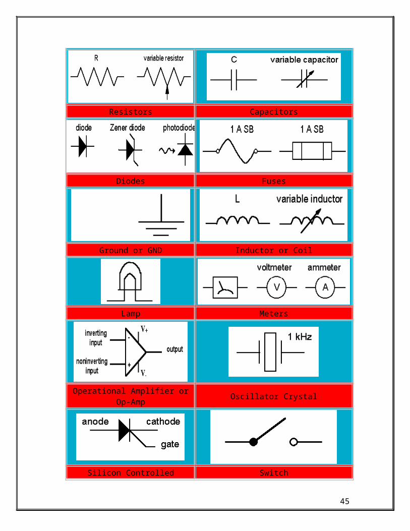
Basic Analog Electronic SymbolsElectronic Symbols
Resistors Capacitors
Diodes Fuses
Ground or GND Inductor or Coil
Lamp Meters
32

Operational Amplifier or Op-Amp Oscillator Crystal
Silicon Controlled Rectifier or SCR Switch
Iron Core Transformer Bi-Polar Transistors
33

ELECTRONIC SYMBOLS CONTINUED
COMPONENT SYMBOL ALTERNATE
Ammeter
And Gate
Antenna, Balanced
Antenna, General
Antenna, Loop, Shielded
Antenna, Loop, Unshielded
Antenna, Unbalanced
Attenuator, Fixed
Attenuator, Variable
Battery
Capacitor, Feedthrough
Capacitor, Fixed, Nonpolarized
Capacitor, Fixed, Polarized
Capacitor, Ganged, Variable
Capacitor, General
Capacitor, Variable, Single
Capacitor, Variable, Split-Stator
Cathode, Cold
Cathode, Directly Heated
Cathode, Indirectly Heated
34
Cavity Resonator
Cell
Circuit Breaker
Coaxial Cable
Crystal, Piezoelectric
Delay Line
Diode, General
Diode, Gunn
Diode, Light-Emitting
Diode, Photosensitive
Diode, Photovoltaic
Diode, Pin
Diode, Varactor
Diode, Zener
Directional Coupler
Exclusive-Or Gate
Female Contact, General
Ferrite Bead
Fuse
Galvanometer
Ground, Chassis
Ground, Earth
35

Handset
Headphone, Double
Headphone, Single
Inductor, Air-Core
Inductor, Bifilar
Inductor, Iron-Core
Inductor, Tapped
Inductor, Variable
Integrated Circuit
Inverter
Jack, Coaxial
Jack, Phone, 2-Conductor
Jack, Phone, 2-Conductor Interrupting
Jack, Phone, 3-Conductor
Jack, Phono
Key, Telegraph
Lamp, Incandescent
Lamp, Neon
Male Contact, General
Microphone
Nand Gate
Negative Voltage Connection
36

Nor Gate
Operational Amplifier
Or Gate
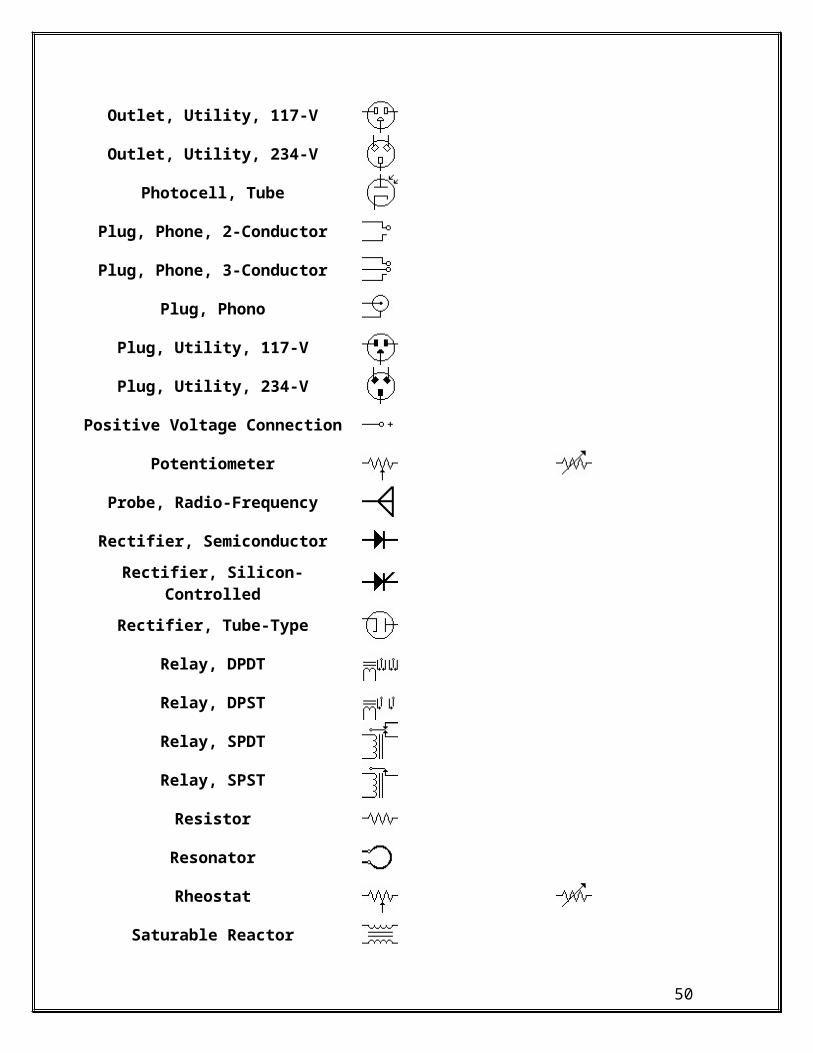
Outlet, Utility, 117-V
Outlet, Utility, 234-V
Photocell, Tube
Plug, Phone, 2-Conductor
Plug, Phone, 3-Conductor
Plug, Phono
Plug, Utility, 117-V
Plug, Utility, 234-V
Positive Voltage Connection
Potentiometer
Probe, Radio-Frequency
Rectifier, Semiconductor
Rectifier, Silicon-Controlled
Rectifier, Tube-Type
Relay, DPDT
Relay, DPST
Relay, SPDT
Relay, SPST
Resistor
37

Resonator
Rheostat
Saturable Reactor
Shielding
Signal Generator
Speaker
Switch, DPDT
Switch, DPST
Switch, Momentary-Contact
Switch, Rotary
Switch, SPDT
Switch, SPST
Terminals, General, Balanced
Terminals, General, Unbalanced
Test Point
Thermocouple
Thyristor
Transformer, Air-Core
Transformer, Iron-Core
Transformer, Tapped Primary
Transformer, Tapped Secondary
Transistor, Bipolar, npn
38
Transistor, Bipolar, pnp
Transistor, Field-Effect, N-Channel
Transistor, Field-Effect, P-Channel
Transistor, Metal-Oxide, Dual-Gate
Transistor, Metal-Oxide, Single-Gate
Transistor, Photosensitive
Transistor, Unijunction
Tube, Diode
Tube, Pentode
Tube, Photomultiplier
Tube, Tetrode
Tube, Triode
Unspecified Component
Voltmeter
Wattmeter
Wires
Wires, Connected, Crossing
Wires, Not Connected, Crossing
39

40

Capacitor Operation
41

Inside View of Electrolytic Capacitor
42

Voltaic Pile
43
Mercury Button Cell
44
NAME: LEVEL: DATE:
CHECK LIST FOR SOLID STATE & DIGITAL ELECTRONICS PACKET
STEPS/TASKS MEETS NEEDS STANDARDS IMPROVEMENT
1) THE STUDENT COMPLETED ALL VOCABULARY TO 100% ACCURACY.2) THE STUDENT COMPLETED ALL WRITTEN WORK TO 100% ACCURACY.3) THE STUDENT COMPLETED THE WRITTEN ASSESSMENT TO 80% ACCURACY.4) THE STUDENT COMPLETED PERFRMANCE SECTION TO 100% ACCURACY.
* ALL STEPS/TASKS MUST MEET THE STANDARDS IN ORDER TO ACHIEVE MASTERY.*
COMMENTS:
INSTRUCTOR SIGNATURE: DATE:
45

Projects
1. Record the color combinations for the following resistors: (I.E: 300 ohm = Orange, Black, Brown).
100 Ohm:
2.2 K Ohm:
50 Ohm:
10 ohm:
5K Ohm:
10K Ohm:
24 Ohm:
99 Ohm:
75 Ohm:
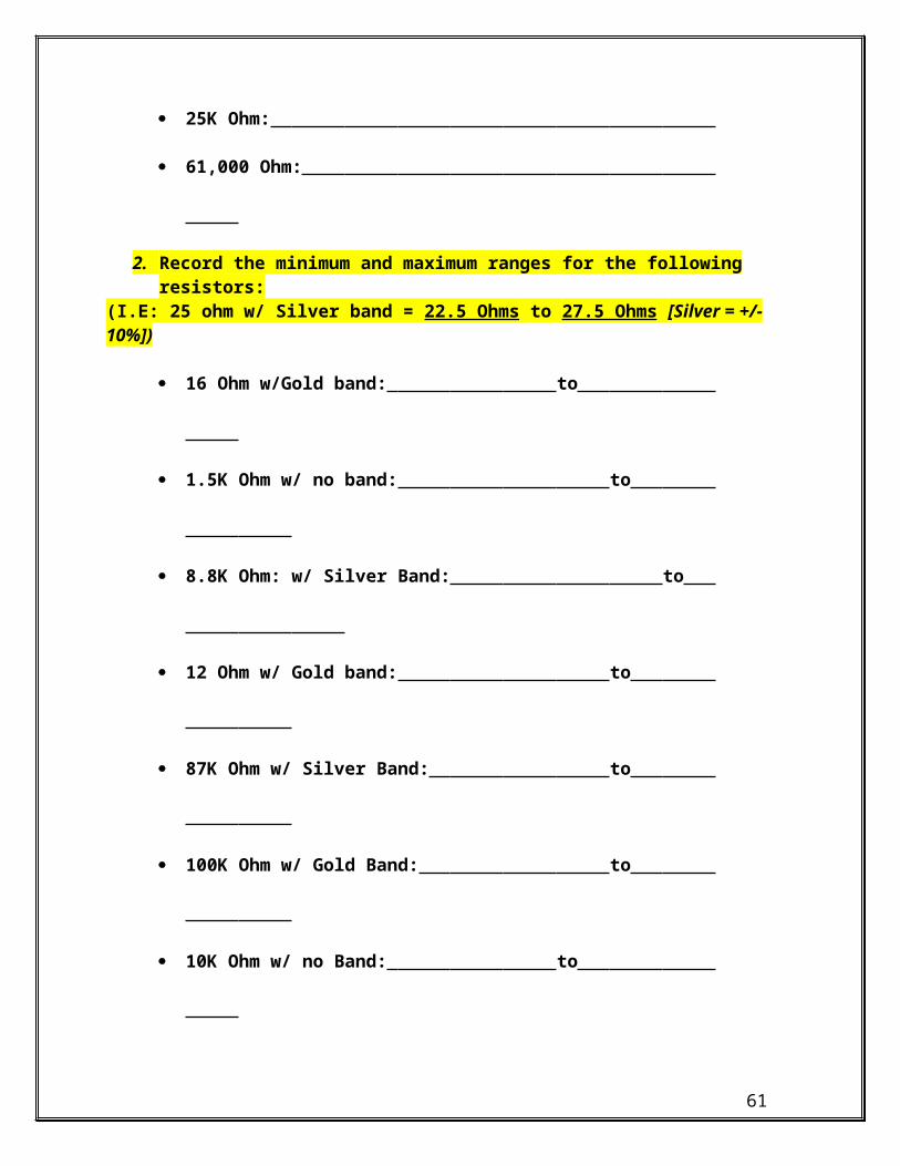
25K Ohm:
61,000 Ohm:
2. Record the minimum and maximum ranges for the following resistors: (I.E: 25 ohm w/ Silver band = 22.5 Ohms to 27.5 Ohms [Silver = +/- 10%])
16 Ohm w/Gold band: to
1.5K Ohm w/ no band: to
8.8K Ohm: w/ Silver Band: to
46

12 Ohm w/ Gold band: to
87K Ohm w/ Silver Band: to
100K Ohm w/ Gold Band: to
10K Ohm w/ no Band: to
50K ohm w/ Gold Band: to
3. The student will calculate and build a series/parallel circuit. Student will get the N.O.C.T.I. Kit from cabinet #2.
The student will arrange three resistors’ (100 ohm, 2.2k ohm, and 1k ohm) onto the bread board. The 100 ohm resistor will be in series with the 2.2k ohm and the 1k ohm that are connected in parallel.
The student will solder all connections together using supplied jumpers.
The student will then solder in the connector for the 9 volt battery.
[****Polarization is a must when working with D.C. voltage****]
The student will connect the 9 volt power supply to the circuit.
The student will then record the following readings:
o Total battery voltage:
o Total resistance of circuit:
o Current between R1 (100 ohm) & R2/R3 2.2k & 1k ohm resistors):
o Total current in circuit:
o Total wattage of circuit:
47

4. The student will then calculate the same circuit using the exact readings of the components. You are going to calculate how it comes out using perfect numbers and compare the readings to the ones you recorded. (Perfect Numbers vs. Actual Readings)
o Total battery voltage:
o Total resistance of circuit:
o Current between R1 (100 ohm) & R2/R3 2.2k & 1k ohm resistors):
o Total current in circuit:
o Total wattage of circuit:
5. Explain why the exact readings differed from the actual readings (Be specific):
Name: Date:
SOLID STATE AND DIGITAL FUNCTIONS POST TEST
Multiple ChoiceIdentify the choice that best completes the statement or answers the question.
____ 1. Solid-state devices are often calleda. conductors c. semi-insulatorsb. semiconductors d. insulators
____ 2. Valence electrons are electrons in thea. inner orbit of an atom c. nucleus of an atomb. outer orbit of an atom d. center of an atom
____ 3. Conductors are generally made from materials that havea. large atoms c. charged atomsb. small atoms d. neutral atoms
____ 4. Insulators are generally made from materials that havea. large atoms c. charged atomsb. small atoms d. neutral atoms
____ 5. Materials that are neither good conductors nor good insulators are known as
48

a. valence conductors c. lattice conductorsb. valence insulators d. semiconductors
____ 6. Semiconductors are made from materials that have how many valence electrons in their outer orbits?a. One c. Fourb. Two d. Eight
____ 7. Silicon is considered a gooda. conductor c. insulatorb. semiconductor d. none of the above
____ 8. To make a semiconductor material useful in the production of solid-state components, it is mixed with a (an)a. insulator c. another semiconductorb. conductor d. impurity
____ 9. Electronsa. have a negative charge c. are neutralb. have a positive charge d. are made of holes
____ 10. A material with a positive charge is called a (an)a. N-type material c. neutral materialb. P-type material d. semiconductor
____ 11. A material with a negative charge is called a (an)a. N-type material c. neutral materialb. P-type material d. semiconductor
____ 12. A device made by joining a piece of P-type material and a piece of N-type material is aa. resistor c. diodeb. transistor d. triode
____ 13. The voltage drop across a zener diodea. varies directly with currentb. varies indirectly with currentc. is a function of the load resistor valued. is constant
____ 14. In a zener circuit the supply voltagea. must be greater than the zener voltageb. must be less than the zener voltagec. must be equal to the zener voltaged. is a function of load current
49
____ 15. Referring to the figure above, if the supply voltage is 25 volts, the current through R1 isa. 80 mA c. 130 mAb. 100 mA d. 200 mA
____ 16. Referring to the figure above, if R2 was changed to 300 ohms, the maximum current that can flow through the load circuit isa. 20 mA c. 60 mAb. 40 mA d. 100 mA
____ 17. The purpose of a zener diode is toa. regulate current c. regulate wattageb. regulate voltage d. regulate load resistance
____ 18. A transistor is made by connectinga. two pieces of semiconductor materialb. three pieces of semiconductor materialc. four pieces of semiconductor materiald. six pieces of semiconductor material
____ 19. A forward biased NPN transistor must have aa. positive voltage on its collector, a negative voltage on its emitter, and a negative voltage
on its baseb. negative voltage on its collector, a positive voltage on its emitter, and a positive voltage on
its basec. negative voltage on its collector, a positive voltage on its emitter, and a negative voltage
on its based. positive voltage on its collector, a negative voltage on its emitter, and a positive voltage on
its base____ 20. A forward biased PNP transistor must have a
a. positive voltage on its emitter, a negative voltage on its collector, and a negative voltage
50

on its baseb. positive voltage on its emitter, a negative voltage on its collector, and a positive voltage on
its basec. negative voltage on its emitter, a positive voltage on its collector, and a negative voltage
on its based. negative voltage on its emitter, a positive voltage on its collector, and a positive voltage on
its base____ 21. In an NPN transistor, the arrow on the emitter points in the direction of
a. electron current flow c. conventional current flowb. the higher voltage point d. collector voltage
____ 22. An NPN transistor will appear to an ohmmeter to bea. two diodes with one anode and one cathode connected togetherb. two diodes completely isolated from each otherc. two diodes with their cathodes connectedd. two diodes with their anodes connected
____ 23. In a transistor, the base-emitter currenta. is the same as the collector-emitter currentb. is less than the collector-emitter currentc. is greater than the collector-emitter currentd. flows in the opposite direction of the collector-emitter current
____ 24. If a transistor, operating as a linear device with a gain of 100, has 3 mA of current flowing through its base-emitter junction,a. 3 mA flows through its collector-emitter junctionb. 300 mA flows through its collector-emitter junctionc. 0.03 mA flows through its collector-emitter junctiond. 0.3 mA flows through its collector-emitter junction
____ 25. A transistor can be operated asa. a digital device only c. a digital or an analog deviceb. an analog device only d. neither a digital or an analog device
____ 26. With a T05 transistor case style, the metal tab on the case isa. closest to the emitterb. closest to the basec. closest to the collectord. of no significants in identifying the emitter, base, or collector leads
____ 27. With a T03 transistor case style, the case itself isa. the emitter c. the collectorb. the base d. none of the above
____ 28. A digital device hasa. one state c. four statesb. two states d. an infinite number of states
____ 29. An SCR is made up ofa. two layers of semiconductor materialb. three layers of semiconductor materialc. four layers of semiconductor materiald. five layers of semiconductor material
____ 30. An SCR consists of a (an)
51

a. anode, cathode, base c. base, emitter, cathodeb. anode, cathode, emitter d. cathode, anode, gate
____ 31. Referring to the figure above, if the load resistor was changed to 50 ohms, the SCR would conducta. 1 ampere when turned on c. 3 amperes when turned onb. 2 amperes when turned on d. 4 amperes when turned on
____ 32. When an SCR conducts, the voltage drop across its anode and cathode is approximatelya. 1 volt c. 3 voltsb. 2 volts d. 200 volts
____ 33. If an SCR has a 4 volt drop with 2 amperes of current flowing through it, the SCR is dissipatinga. 2 watts c. 6 wattsb. 4 watts d. 8 watts
____ 34. To turn an SCR on, itsa. anode must be positive, its cathode negative, and its gate must receive a positive chargeb. anode must be negative, its cathode positive, and its gate must receive a positive chargec. anode must be positive, its cathode negative, and its gate must receive a negative charged. anode must be negative, its cathode positive, and its gate must receive a negative charge
____ 35. The amount of current required to keep an SCR turned on is called thea. trigger current c. holding currentb. threshold current d. break down current
____ 36. When an SCR fires, current flows througha. the gate to the anode c. the anode-cathode sectionb. the gate to the cathode d. none of the above
____ 37. When an SCR fires, itsa. anode-gate section becomes a short circuitb. anode-cathode section becomes a short circuitc. cathode-gate section becomes a short circuitd. anode-cathode section becomes an open circuit
____ 38. With a typical SCR, thea. gate current and holding current are equalb. gate current is greater than the holding currentc. gate current is less than the holding currentd. gate current is at least 20 times greater than the holding current
____ 39. When an SCR is connected in an ac circuit, the output isa. alternating current c. zero currentb. direct current d. alternating voltage
____ 40. To fire an SCR in an ac circuit, it must be
52

a. forward biased while its gate receives a positive chargeb. reverse biased while its gate receives a positive chargec. forward biased while its gate receives a negative charged. reversed biased while its gate receives a negative charge
____ 41. Referring to the figure below, the voltage across the load can be adjusted from
a. 0 to half the applied voltageb. 0 to the full applied voltagec. half the applied voltage to the full applied voltaged. 0 to one-fourth the applied voltage
____ 42. The diac is a special-purposea. unidirectional diode c. bidirectional transistorb. bidirectional diode d. bidirectional SCR
____ 43. The primary function of a diac is to phase shifta. a UJT c. an SCRb. a diode d. a triac
____ 44. A diac is similar to a (an)a. common transistor c. triacb. SCR d. UJT
____ 45. When a diac fires, it displays aa. positive resistance c. zero resistanceb. negative resistance d. infinite resistance
____ 46. A diac conducts ata. a lower voltage than that needed to turn it onb. a higher voltage than that needed to turn it onc. the same voltage needed to turn it ond. twice the voltage needed to turn it on
____ 47. A diac conductsa. on only one side of an ac cycle c. in a dc circuit onlyb. on either side of an ac cycle d. in a 60 Hz ac circuit only
____ 48. A diac is aa. current sensitive dc switch c. voltage sensitive dc switchb. current sensitive ac switch d. voltage sensitive ac switch
____ 49. A triac operates as a back to backa. diode c. diacb. unijunction transistor d. silicon-controlled rectifier
53

____ 50. When a triac is connected in a circuit, the output voltage results in a (an)a. pulsating direct current c. alternating currentb. pulsating alternating current d. direct current
____ 51. A triac operates in a manner similar to twoa. SCRs with a common anode c. SCRs with a common gateb. SCRs with a common cathode d. UJTs with a common base
____ 52. A triac requiresa. a holding current but no gate currentb. a gate current but no holding currentc. both a holding current and a gate currentd. neither a holding current or a gate current
____ 53. A triac hasa. one state of operation c. three states of operationb. two states of operation d. four states of operation
____ 54. When a triac is turned on, it dropsa. zero volts with circuit current limited by the gate resistanceb. zero volts with circuit current limited by the load resistancec. about 1 volt with circuit current limited by the gate resistanced. about 1 volt with circuit current limited by the load resistance
____ 55. A triac works well in industrial circuits as a (an)a. dc switch c. pulsating switchb. ac switch d. holding switch
____ 56. If a triac is fired when the ac waveform reaches its peak value,a. half the ac voltage is dropped across the triac and half across the loadb. none of the ac voltage is dropped across the triac and all the voltage is dropped across the
loadc. all the ac voltage is dropped across the triac and none is dropped across the loadd. none of the ac voltage is dropped across the triac and none across the load
____ 57. Referring to the figure above, aa. resistor is used to phase shift the triacb. diode is used to phase shift the triacc. diac is used to phase shift the triacd. capacitor is used to phase shift the triac
54

____ 58. Referring to the figure above, when the triac turns on,a. capacitor C1 charges through the gate of the triacb. capacitor C1 discharges through the gate of the triacc. capacitor C1 charges through the MT1 terminal of the triacd. capacitor C1 discharges through the MT1 terminal of the triac
____ 59. Which is not true of a solid-state relay?a. It has no moving partsb. It is sealed against dirtc. It is resistant to shock and vibrationd. It requires a relatively high operating voltage
____ 60. With an opto-isolator, coupling from the control circuit to the load circuit is accomplished witha. heat c. electrical pulsesb. light d. electromagnetism
____ 61. Solid-state relays designed for use as ac controllers use a (an)a. diac in the load circuit c. power transistor in the load circuitb. triac in the load circuit d. SCR in the load circuit
____ 62. With a reed switch, coupling from the control circuit to the load circuit is accomplished witha. heat c. electrical pulsesb. light d. electromagnetism
____ 63. Zero switching is used primarily witha. resistive loads c. inductive loadsb. capacitive loads d. pulsed loads
____ 64. Which is not an important factor in the installation of limit switches?a. Operating force c. Sizeb. Stroke d. Power distribution
____ 65. The best material for use in a Hall generator isa. gold c. a semiconductorb. silver d. an insulator
____ 66. In a Hall effect, aa. constant current flows through a semiconductor materialb. constant voltage is placed across a semiconductor materialc. constant current flows through a conducting materiald. constant voltage is placed across a conducting material
____ 67. With a Hall generator, an externala. electrical field is brought near the Hall sensorb. heating element is brought near the Hall sensorc. magnetic field is brought near the Hall sensord. none of the above
____ 68. The amount of voltage produced by a Hall generator is determined bya. the amount of current flowing through its semiconductor materialb. the strength of the magnetic field used to deflect the current pathc. a and bd. neither a or b
____ 69. A Hall generator is constructed as a (an)a. coiled device c. capacitive deviceb. vacuum device d. integrated circuit
55

____ 70. If a disk with magnetic poles around its circumference is attached to a rotating shaft, and a Hall sensor is mounted near the disk, a (an)a. steady dc voltage will be producedb. pulsating dc voltage will be producedc. ac voltage will be producedd. all of the above
____ 71. A sensor used to shunt a magnetic field away from some other object is known as aa. detector c. pulserb. reactor d. reluctor
____ 72. A reluctor circuit will produce a (an)a. dc voltage c. ac voltageb. pulsating dc voltage d. zero voltage
____ 73. A Hall generator can be used in a manner similar to aa. limit switch c. hydraulic switchb. pressure switch d. all of the above
____ 74. A Hall effect limit switch usesa. a magnetic plunger c. normally open contactsb. rotating contacts d. normally closed contacts
____ 75. A Hall generator can operate at pulse rates as high asa. 1000 pulses per second c. 100,000 pulses per secondb. 10,000 pulses per second d. 1,000,000 pulses per second
Residential & Industrial ElectricityK-W-L WORKSHEET
NAME: LEVEL: DATE:
ARTICLE TITLE:
TIME START: TIME FINISH:
K What do I already KNOW about this topic?
56

W What do I WANT to know about this topic?
L What did I LEARN after reading ABOUT this topic?
I checked the following before reading: Headlines and Subheadings Italic, Bold, and Underlined words Pictures, Tables, and Graphs Questions or other key information
I made predictions AFTER previewing the article.
Comments:
Instructor Signature:
Instructional Aide Signature:
Name: Date:
SOLID STATE AND DIGITAL FUNCTIONS PRE TEST
Multiple ChoiceIdentify the choice that best completes the statement or answers the question.
____ 1. Solid-state devices are often calleda. conductors c. semi-insulatorsb. semiconductors d. insulators
____ 2. Valence electrons are electrons in thea. inner orbit of an atom c. nucleus of an atomb. outer orbit of an atom d. center of an atom
57

____ 3. Conductors are generally made from materials that havea. large atoms c. charged atomsb. small atoms d. neutral atoms
____ 4. Insulators are generally made from materials that havea. large atoms c. charged atomsb. small atoms d. neutral atoms
____ 5. Materials that are neither good conductors nor good insulators are known asa. valence conductors c. lattice conductorsb. valence insulators d. semiconductors
____ 6. Semiconductors are made from materials that have how many valence electrons in their outer orbits?a. One c. Fourb. Two d. Eight
____ 7. Silicon is considered a gooda. conductor c. insulatorb. semiconductor d. none of the above
____ 8. To make a semiconductor material useful in the production of solid-state components, it is mixed with a (an)a. insulator c. another semiconductorb. conductor d. impurity
____ 9. Electronsa. have a negative charge c. are neutralb. have a positive charge d. are made of holes
____ 10. A material with a positive charge is called a (an)a. N-type material c. neutral materialb. P-type material d. semiconductor
____ 11. A material with a negative charge is called a (an)a. N-type material c. neutral materialb. P-type material d. semiconductor
____ 12. A device made by joining a piece of P-type material and a piece of N-type material is aa. resistor c. diodeb. transistor d. triode
____ 13. The voltage drop across a zener diodea. varies directly with currentb. varies indirectly with currentc. is a function of the load resistor valued. is constant
____ 14. In a zener circuit the supply voltagea. must be greater than the zener voltageb. must be less than the zener voltagec. must be equal to the zener voltaged. is a function of load current
58

____ 15. Referring to the figure above, if the supply voltage is 25 volts, the current through R1 isa. 80 mA c. 130 mAb. 100 mA d. 200 mA
____ 16. Referring to the figure above, if R2 was changed to 300 ohms, the maximum current that can flow through the load circuit isa. 20 mA c. 60 mAb. 40 mA d. 100 mA
____ 17. The purpose of a zener diode is toa. regulate current c. regulate wattageb. regulate voltage d. regulate load resistance
____ 18. A transistor is made by connectinga. two pieces of semiconductor materialb. three pieces of semiconductor materialc. four pieces of semiconductor materiald. six pieces of semiconductor material
____ 19. A forward biased NPN transistor must have aa. positive voltage on its collector, a negative voltage on its emitter, and a negative voltage
on its baseb. negative voltage on its collector, a positive voltage on its emitter, and a positive voltage on
its basec. negative voltage on its collector, a positive voltage on its emitter, and a negative voltage
on its based. positive voltage on its collector, a negative voltage on its emitter, and a positive voltage on
its base____ 20. A forward biased PNP transistor must have a
a. positive voltage on its emitter, a negative voltage on its collector, and a negative voltage
59

on its baseb. positive voltage on its emitter, a negative voltage on its collector, and a positive voltage on
its basec. negative voltage on its emitter, a positive voltage on its collector, and a negative voltage
on its based. negative voltage on its emitter, a positive voltage on its collector, and a positive voltage on
its base____ 21. In an NPN transistor, the arrow on the emitter points in the direction of
a. electron current flow c. conventional current flowb. the higher voltage point d. collector voltage
____ 22. An NPN transistor will appear to an ohmmeter to bea. two diodes with one anode and one cathode connected togetherb. two diodes completely isolated from each otherc. two diodes with their cathodes connectedd. two diodes with their anodes connected
____ 23. In a transistor, the base-emitter currenta. is the same as the collector-emitter currentb. is less than the collector-emitter currentc. is greater than the collector-emitter currentd. flows in the opposite direction of the collector-emitter current
____ 24. If a transistor, operating as a linear device with a gain of 100, has 3 mA of current flowing through its base-emitter junction,a. 3 mA flows through its collector-emitter junctionb. 300 mA flows through its collector-emitter junctionc. 0.03 mA flows through its collector-emitter junctiond. 0.3 mA flows through its collector-emitter junction
____ 25. A transistor can be operated asa. a digital device only c. a digital or an analog deviceb. an analog device only d. neither a digital or an analog device
____ 26. With a T05 transistor case style, the metal tab on the case isa. closest to the emitterb. closest to the basec. closest to the collectord. of no significants in identifying the emitter, base, or collector leads
____ 27. With a T03 transistor case style, the case itself isa. the emitter c. the collectorb. the base d. none of the above
____ 28. A digital device hasa. one state c. four statesb. two states d. an infinite number of states
____ 29. An SCR is made up ofa. two layers of semiconductor materialb. three layers of semiconductor materialc. four layers of semiconductor materiald. five layers of semiconductor material
____ 30. An SCR consists of a (an)
60
a. anode, cathode, base c. base, emitter, cathodeb. anode, cathode, emitter d. cathode, anode, gate
____ 31. Referring to the figure above, if the load resistor was changed to 50 ohms, the SCR would conducta. 1 ampere when turned on c. 3 amperes when turned onb. 2 amperes when turned on d. 4 amperes when turned on
____ 32. When an SCR conducts, the voltage drop across its anode and cathode is approximatelya. 1 volt c. 3 voltsb. 2 volts d. 200 volts
____ 33. If an SCR has a 4 volt drop with 2 amperes of current flowing through it, the SCR is dissipatinga. 2 watts c. 6 wattsb. 4 watts d. 8 watts
____ 34. To turn an SCR on, itsa. anode must be positive, its cathode negative, and its gate must receive a positive chargeb. anode must be negative, its cathode positive, and its gate must receive a positive chargec. anode must be positive, its cathode negative, and its gate must receive a negative charged. anode must be negative, its cathode positive, and its gate must receive a negative charge
____ 35. The amount of current required to keep an SCR turned on is called thea. trigger current c. holding currentb. threshold current d. break down current
____ 36. When an SCR fires, current flows througha. the gate to the anode c. the anode-cathode sectionb. the gate to the cathode d. none of the above
____ 37. When an SCR fires, itsa. anode-gate section becomes a short circuitb. anode-cathode section becomes a short circuitc. cathode-gate section becomes a short circuitd. anode-cathode section becomes an open circuit
____ 38. With a typical SCR, thea. gate current and holding current are equalb. gate current is greater than the holding currentc. gate current is less than the holding currentd. gate current is at least 20 times greater than the holding current
____ 39. When an SCR is connected in an ac circuit, the output isa. alternating current c. zero currentb. direct current d. alternating voltage
____ 40. To fire an SCR in an ac circuit, it must be
61

a. forward biased while its gate receives a positive chargeb. reverse biased while its gate receives a positive chargec. forward biased while its gate receives a negative charged. reversed biased while its gate receives a negative charge
____ 41. Referring to the figure below, the voltage across the load can be adjusted from
a. 0 to half the applied voltageb. 0 to the full applied voltagec. half the applied voltage to the full applied voltaged. 0 to one-fourth the applied voltage
____ 42. The diac is a special-purposea. unidirectional diode c. bidirectional transistorb. bidirectional diode d. bidirectional SCR
____ 43. The primary function of a diac is to phase shifta. a UJT c. an SCRb. a diode d. a triac
____ 44. A diac is similar to a (an)a. common transistor c. triacb. SCR d. UJT
____ 45. When a diac fires, it displays aa. positive resistance c. zero resistanceb. negative resistance d. infinite resistance
____ 46. A diac conducts ata. a lower voltage than that needed to turn it onb. a higher voltage than that needed to turn it onc. the same voltage needed to turn it ond. twice the voltage needed to turn it on
____ 47. A diac conductsa. on only one side of an ac cycle c. in a dc circuit onlyb. on either side of an ac cycle d. in a 60 Hz ac circuit only
____ 48. A diac is aa. current sensitive dc switch c. voltage sensitive dc switchb. current sensitive ac switch d. voltage sensitive ac switch
____ 49. A triac operates as a back to backa. diode c. diacb. unijunction transistor d. silicon-controlled rectifier
62

____ 50. When a triac is connected in a circuit, the output voltage results in a (an)a. pulsating direct current c. alternating currentb. pulsating alternating current d. direct current
____ 51. A triac operates in a manner similar to twoa. SCRs with a common anode c. SCRs with a common gateb. SCRs with a common cathode d. UJTs with a common base
____ 52. A triac requiresa. a holding current but no gate currentb. a gate current but no holding currentc. both a holding current and a gate currentd. neither a holding current or a gate current
____ 53. A triac hasa. one state of operation c. three states of operationb. two states of operation d. four states of operation
____ 54. When a triac is turned on, it dropsa. zero volts with circuit current limited by the gate resistanceb. zero volts with circuit current limited by the load resistancec. about 1 volt with circuit current limited by the gate resistanced. about 1 volt with circuit current limited by the load resistance
____ 55. A triac works well in industrial circuits as a (an)a. dc switch c. pulsating switchb. ac switch d. holding switch
____ 56. If a triac is fired when the ac waveform reaches its peak value,a. half the ac voltage is dropped across the triac and half across the loadb. none of the ac voltage is dropped across the triac and all the voltage is dropped across the
loadc. all the ac voltage is dropped across the triac and none is dropped across the loadd. none of the ac voltage is dropped across the triac and none across the load
____ 57. Referring to the figure above, aa. resistor is used to phase shift the triacb. diode is used to phase shift the triacc. diac is used to phase shift the triacd. capacitor is used to phase shift the triac
____ 58. Referring to the figure above, when the triac turns on,a. capacitor C1 charges through the gate of the triac
63

b. capacitor C1 discharges through the gate of the triacc. capacitor C1 charges through the MT1 terminal of the triacd. capacitor C1 discharges through the MT1 terminal of the triac
____ 59. Which is not true of a solid-state relay?a. It has no moving partsb. It is sealed against dirtc. It is resistant to shock and vibrationd. It requires a relatively high operating voltage
____ 60. With an opto-isolator, coupling from the control circuit to the load circuit is accomplished witha. heat c. electrical pulsesb. light d. electromagnetism
____ 61. Solid-state relays designed for use as ac controllers use a (an)a. diac in the load circuit c. power transistor in the load circuitb. triac in the load circuit d. SCR in the load circuit
____ 62. With a reed switch, coupling from the control circuit to the load circuit is accomplished witha. heat c. electrical pulsesb. light d. electromagnetism
____ 63. Zero switching is used primarily witha. resistive loads c. inductive loadsb. capacitive loads d. pulsed loads
____ 64. Which is not an important factor in the installation of limit switches?a. Operating force c. Sizeb. Stroke d. Power distribution
____ 65. The best material for use in a Hall generator isa. gold c. a semiconductorb. silver d. an insulator
____ 66. In a Hall effect, aa. constant current flows through a semiconductor materialb. constant voltage is placed across a semiconductor materialc. constant current flows through a conducting materiald. constant voltage is placed across a conducting material
____ 67. With a Hall generator, an externala. electrical field is brought near the Hall sensorb. heating element is brought near the Hall sensorc. magnetic field is brought near the Hall sensord. none of the above
____ 68. The amount of voltage produced by a Hall generator is determined bya. the amount of current flowing through its semiconductor materialb. the strength of the magnetic field used to deflect the current pathc. a and bd. neither a or b
____ 69. A Hall generator is constructed as a (an)a. coiled device c. capacitive deviceb. vacuum device d. integrated circuit
64
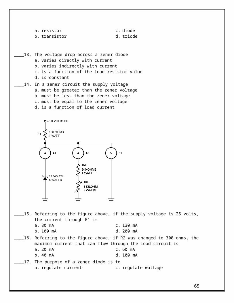
____ 70. If a disk with magnetic poles around its circumference is attached to a rotating shaft, and a Hall sensor is mounted near the disk, a (an)a. steady dc voltage will be producedb. pulsating dc voltage will be producedc. ac voltage will be producedd. all of the above
____ 71. A sensor used to shunt a magnetic field away from some other object is known as aa. detector c. pulserb. reactor d. reluctor
____ 72. A reluctor circuit will produce a (an)a. dc voltage c. ac voltageb. pulsating dc voltage d. zero voltage
____ 73. A Hall generator can be used in a manner similar to aa. limit switch c. hydraulic switchb. pressure switch d. all of the above
____ 74. A Hall effect limit switch usesa. a magnetic plunger c. normally open contactsb. rotating contacts d. normally closed contacts
____ 75. A Hall generator can operate at pulse rates as high asa. 1000 pulses per second c. 100,000 pulses per secondb. 10,000 pulses per second d. 1,000,000 pulses per second
65