Embed Size (px)
Citation preview

Forces
P P I • p p i 2 p a s s . c o m
Second floor to third floor
The column supports the floor live load from the thirdand fourth floor. The influence area is the sum of theinfluence areas at the third and fourth floors.
A K A2
(2)(4)(900†ft )
7200†ft
400†ft [IBC†Eq.†16-23†is†applicable]
I LL T2
2
2
=
=
=>
The reduced live load at the third floor is
L LK A
L
0.2515
50†lbf
ft0.25
15
7200†ft
21.34†lbf/ft
0.4
[satisfactory]
[minimum†for†member†supporting†two†floors]
oLL T
o
2 2
2
= +
= +
=>
In accordance with IBC Sec. 1607.5, an additional15 lbf/ft2 must be added to allow for the nonreducibleweight of moveable partitions. Hence, the total live loadintensity is
L 21.34†lbf
ft15†
lbf
ft
36.34†lbf/ft
2 2
2
= +
=
The live load is
W LA36.34†
lbf
ft(900†ft )
1000†lbfkip
32.71†kips
T
22
= =
=
The total live load above the second floor is
W W W 32.71†kips 36†kips
68.71†kips2 3= + = +
=
First floor to second floorThe column supports the floor live load from the second,third, and fourth floor. From IBC Table 1607.1, the dis-tributed live load on the second floor may not bereduced, and
L L 100†lbf/fto2= =
Since L is greater than 80 lbf/ft2, the partition load of15 lbf/ft2 is not added to the floor load in accordancewith IBC Sec. 1607.5.
The additional load applied to the column by the secondfloor distributed live load is
W LA100†
lbf
ft(900†ft )
1000†lbfkip
90†kips
T
22
= =
=
The total live load above the first floor is
W W W 90†kips 68.71†kips
158.71†kips1 2= + = +
=
Distribution of Floor LoadsFor continuous floor members, IBC Sec. 1607.11requires that the design force on a member be deter-mined using the most adverse distribution of the liveload. For continuous beams, this requires analysis of theloading arrangements shown in Fig. 1.8 using skip orcheckerboard loading to determine maximum span andsupport moments.
Figure 1.8 Partial Loading Conditions
max. positivemoment
(a) alternate spans
max. negativemoment
1 2 3 4 5 6 7 8
max.reaction
(b) two adjacent spans
max. negativemoment
1 2 3 4 5 6 7 8
In Fig. 1.8(a), alternate spans are loaded. This producesmaximum positive moments at the center of the loadedspans 12, 34, 56, and 78. This also produces maximumnegative moments at the center of the unloaded spans23, 45, and 67.
In Fig. 1.8(b), two adjacent spans are loaded with alter-nate spans loaded beyond these. This produces maximumnegative moment and maximum shear at support 4.
To simplify the procedure, ACI Sec. 6.4.2 allows consid-eration of the following modified arrangements.
1-13V E R T I C A L , I N C I D E N T A L L A T E R A L , A N D O T H E R V A R I A B L E F O R C E S 1-13
Forces
P P I • p p i 2 p a s s . c o m
The maximum active pressure at the bottom of the heel is
p K h
(0.27) 120†lbf
ft(15†ft)
486†lbf/ft
A A S
3
2
=
=
=
For a 1 ft length of wall, the total horizontal force on theretaining wall is
Hp h2
486†lbf
ft(15†ft)
(2) 1000†lbfkip
3.65†kips/ft
AA
2
=
=
=
Passive Pressure
For the retaining wall shown in Fig. 1.35(c), which isconstructed on a soil with a density of γS and an angle ofinternal friction of φ, the passive earth pressure that canbe developed in front of the key at a depth z belowground surface is given by Rankine’s theory as
p K zP P S=
In this equation, KP is the Rankine coefficient of passiveearth pressure and is
K1 sin
1 sinP =+
The maximum passive pressure occurs at the bottom ofthe key and is
p K hP P S K=
In this equation, hK is the height of the key. The totalhorizontal force on the key due to passive pressure is
Hp h K h
2 2PP K P S K
2
= =
The line of action of the total horizontal force is located(h + hK)/3 above the bottom of the key (see Fig. 1.35(c)).
Example 1.25
The retaining wall shown in Fig. 1.35(c) is constructedon a soil with a density of 120 lbf/ft3 and an angle ofinternal friction of 35°. The total height of the key is5 ft. Determine the total horizontal force per foot of walldue to passive pressure on the key.
Solution
The Rankine coefficient of passive earth pressure is
K1 sin
1 sin
1 sin 351 sin 353.69
P =+
=+ °
°=
The maximum passive pressure that can be developedat the bottom of the key is
p K h
(3.69) 120†lbf
ft(5†ft)
2214†lbf/ft
P P S K
3
2
=
=
=
For a 1 ft length of wall, the total force due to passivepressure that can be developed on the key is
Hp h
2
2214†lbf
ft(5†ft)
(2) 1000†lbfkip
5.54†kips/ft
PP K
2
=
=
=
Hydrostatic Pressure and Soil Lateral Pressure
A retaining wall is usually provided with a drainage sys-tem behind the wall. Where this is not possible andadjacent soil is below the free-water table, design mustinclude the effects of submerged soil pressure plushydrostatic pressure as shown in Fig. 1.36.
For the retaining wall shown in Fig. 1.36, which has asoil backfill with a dry density of γS, the active earthpressure behind the wall at a depth of hdry below the fillsurface is given by Rankine’s theory as
p K hA A S dry=
1-47V E R T I C A L , I N C I D E N T A L L A T E R A L , A N D O T H E R V A R I A B L E F O R C E S 1-47

Reinforced
Concrete
P P I • p p i 2 p a s s . c o m
The development length for a grade 60, no. 8 bar, with2.5 in side cover and 2 in end cover and with a standard90° hook, is given by ACI Sec. 25.4.3.1 as
=
=
=>
ld
f
l
(0.7) 1200†lbf
in
(0.7) 1200†lbf
in(1†in)
4500†lbf
in12.5†in
[Anchorage†length†is†inadequate.]
dh
b
c
a
2
2
2
Use an end plate to anchor the bars.
8. CORBELS........................................................................................................................
A corbel is a cantilever bracket supporting a load-bearing member. As shown in Fig. 2.14 and specified inACI Sec. 16.5.1.1, the shear span-to-depth ratio, av/d,and the ratio of horizontal tensile force to vertical force,Nuc/Vu, are limited to a maximum value of unity. Thedepth of the corbel at the outside edge of bearing areamust not be less than d/2.
At the face of the support, the forces acting on the cor-bel are a shear force, Vu, a moment (Vuav+Nuc(h− d)),and a tensile force, Nuc. These require reinforcementareas of Avf, Af, and An, respectively. The shear frictionreinforcement area is derived from ACI Eq. 22.9.4.2 as
µ=A
Vfvfu
y
Also, from ACI Table 22.9.4.4, the factored shear forceon the section is
µ
+
=
=
V f b d
f b d
b d
0.2
(480 0.08 )
1600
coefficient†of†friction†at†face†of†support,
as†given†by†ACI†22.9.4.2
1.4 [for†concrete†placed†monolithically]
u c w
c w
w
The correction factor related to the unit weight of con-crete is defined by ACI Sec. 19.2.4.2 as
==
1.0
0.75
[for†normal†weight†concrete]
[for†all†lightweight†concrete]
In accordance with ACI Sec. 16.5.3.5, the tensile forceNuc may not be less than 0.2Vu, and the correspondingarea of reinforcement required is
=AN
fnuc
y
The required area of primary tension reinforcement isgiven by ACI Sec. 16.5.5.1 as the greater of
= +
=
A A A
Abd
ff
0.04
sc f n
sc c
y
The minimum required area of closed ties distributedover a depth of 2d/3 is given by ACI Sec. 16.5.5.2 as
=AA A
2hsc n
ACI Table 21.2.1 gives the value of the strength reduc-tion factor for corbels as = 0.75.
Example 2.12
The reinforced concrete corbel shown has a width of15 in, is reinforced with grade 60 bars, and has a
2-27R E I N F O R C E D C O N C R E T E D E S I G N 2-27
Figure 2.14 Corbel Details
anchor bar
framing barto anchorstirrups
dh
Nuc ≤ Vu
Asc (primaryreinforcement)
bearingplate
Vu
av
d23
Ah(closedstirrups)
mind2

Rein
forced
Concrete
P P I • p p i 2 p a s s . c o m
concrete compressive strength of 3000 lbf/in2. Deter-mine whether the corbel is adequate for the applied fac-tored loads indicated.
Nuc = 40 kips
2 in
4 in
20 in
12 in
3–No. 7
3–No. 3(closedstirrups)
anchor bar
Vu = 100 kips
Solution
f b d
V
f b d
Vb d
V
0.2 (0.2)(0.75) 3†kips
in(15†in)(20†in)
135†kips
(480 0.08 ) (0.72)(0.75)(15†in)(20†in)
162†kips
1.6 (1.6)(0.75)(15†in)(20†in)
360†kips
c w
u
c w
u
w
u
2=
=>
+ ==>==>
The corbel conforms to ACI Table 22.9.4.4.
The shear friction reinforcement area is given by ACISec. 22.9.9.2 as
AVf
100†kips
(0.75) 60†kips
in(1.4)
1.59†in
vfu
y2
2
µ= =
=
The tension reinforcement area required is
AN
f40†kips
(0.75) 60†kips
in
0.889†in
nuc
y2
2
= =
=
The factored moment acting on the corbel is
M V a N h d( )
(100†kips)(4†in) (40†kips)(2†in)
480†in-kips
u u v uc= += +=
The area of flexural reinforcement required for φ= 0.75for corbels as given by ACI Sec. R21.2.1 for corbels is
A
bdfM
b d f
f
0.85 1 10.319
0.545†in
f
cu
w c
y
2
2
=
=
The primary reinforcement area required is given byACI Sec. 16.5.5.1 as
A A A
0.545†in 0.889†in
1.434†in
sc f n
2 2
2
= +
= +=
Three no. 7 bars are provided, giving an area of
A 1.80†in
1.434†in [satisfactory]
s2
2
=
>
Also, from ACI Sec. 16.5.5.1, the area of primary rein-forcement must not be less than
AA
A
2
3
(2)(1.59†in )
30.889†in
1.95†in
[unsatisfactory]
vfn
s
22
2
+ = +
=>
The area of closed stirrups required is given by ACISec. 16.5.5.2 as
AA A
2
1.95†in 0.889†in2
0.53†in
hsc n
2 2
2
=
=
=
Three no. 3 closed stirrups are provided, giving an area of
A 0.66†in
0.53†in [satisfactory]
h2
2
=
>
2-282-28 S E S T R U C T U R A L E N G I N E E R I N G R E F E R E N C E M A N U A L
Reinforced
Concrete
P P I • p p i 2 p a s s . c o m
To ensure that allowable bond stresses are not exceeded,ACI Sec. 9.7.3.8.3 requires a bar diameter to be chosensuch that its development length, in the case where theend of the reinforcement is not confined by a compres-sive reaction, is given by
lMV
ldn
ua+
Mn is the nominal strength assuming all reinforcement isstressed to the specified yield stress, fy, Vu is the fac-tored shear force at the section, and la is the embedmentlength beyond the center of the support.Alternatively, if the end of the reinforcement is confinedby a compressive reaction, ACI Sec. 9.7.3.8.3 requires abar diameter to be chosen such that its developmentlength is given by
lMV
l1.3dn
ua+
At a point of inflection, ACI Sec. 9.7.3.8.3 limits theembedment length beyond the point of inflection to thegreater of d or 12db.Alternatively, at a simple support, ACI Sec. 9.7.3.8.3specifies that the reinforcement may terminate in astandard hook or a mechanical anchorage beyond thecenterline of the support.
Example 2.24
Assume that the reinforced concrete beam for Ex. 2.23,which is shown in Fig. 2.20, has a factored end reactionof 30 kips and that the beam frames into concrete gird-ers at each end. Determine whether the two no. 9 barsat the support satisfy the requirements for local bond.
Solution
The development length for the no. 9 bars was given inEx. 2.23 as
l d55 62†ind b= =
The nominal flexural strength at the support is given byACI Sec. 22.2 as
M A f dA f
b df1
0.59
(2†in ) 60†kips
in(16†in)
1
(0.59)(2†in ) 60†kips
in
(12†in)(16†in) 3†kips
in
1684†in-kips
n s ys y
w c
22
22
2
=
=
×
=
For a beam framing into a concrete girder, the appropriatefactors given by ACI Sec. 9.7.3.8.3 are
MV
l
l
1.3†(1.3)(1684†in-kips)
30†kips6†in 79†inn
ua
d
+ = + =
>
Local bond requirements are satisfied.
Development of Negative MomentReinforcementTo allow for variation in the applied loads, ACISec. 9.7.3.8.4 requires a minimum of one-third of thenegative reinforcement at a support to extend past thepoint of inflection at least the greatest of effective depthof the beam, 12 times the bar diameter, or one-sixteenthof the clear span. This is shown in Fig. 2.22.
Figure 2.22 Negative Moment Reinforcement
ln = clear span
PI
⩾ 12db ⩾
⩾ 0.33As As
ln16
⩾ d
Example 2.25
The reinforced concrete continuous beam shown has aneffective depth of 16 in, is reinforced with grade 60 bars,and has a concrete compressive strength of 3000 lbf/in2.Determine the minimum length, x, at which the barsindicated may terminate.
ln = 24 ft
6 ft
x
PI
2–No. 9
2-45R E I N F O R C E D C O N C R E T E D E S I G N 2-45
Steel
P P I • p p i 2 p a s s . c o m
Eleven stress categories are defined in AISC 360Table A-3.1. For stress categories A, B, B′, C, D, E, andE′, the design stress range in the member must notexceed the value given by AISC 360 Eq. A-3-1 as
=FC
n
F
SRf
SR
TH
0.333
For stress category F, the design stress range in themember must not exceed the value given by AISC 360Eq. A-3-2.
=FC
n
F
SRf
SR
TH
0.167
Example 5.34
A tie member in a steel truss consists of a pair of gradeA36 5 in × 5 in × 3
8 in angles fillet welded to a gussetplate. The force in the member, due to dead load only, is90 kips tension. The additional force in the member, dueto live load only, varies from a compression of 7 kips to atension of 50 kips. During the design life of the struc-ture, the live load may be applied 600,000 times. Deter-mine whether fatigue effects are a concern.
Solution
From AISC 360 Table A-3.1, the loading condition ofSec. 4.1 is applicable and the relevant factors are
==
= =××
=
EF
C
n
stress†categoryallowable†stress†range
11 10
6 10
12.21†kips/in
SR
f
SR
0.333 8
5
0.333
2
The area of the tie is
=A 7.22†ins2
The actual stress range is
= =
=<
fT T
A
F
50†kips ( 7†kips)
7.22†in
7.9†kips/in F[exceeds† ]
SRs
TH
SR
max min2
2
This is within the allowable stress range, so fatigueeffects need not be considered.
8. DESIGN OF BOLTED CONNECTIONS........................................................................................................................
Nomenclature
Ab nominal unthreaded body area of bolt in2
C coefficient for eccentrically loaded bolt andweld groups
–
d nominal bolt diameter indm moment arm between resultant tensile and
compressive forces due to an eccentric forcein
dn nominal hole diameter –Du a multiplier that reflects the ratio of the
mean installed bolt tension to the specifiedminimum bolt pretension
–
frv required shear stress kips/in2
fv computed shear stress kips/in2
Fnt nominal tensile stress of bolt kips/in2
Fntnominal tensile stress of a bolt subjected tocombined shear and tension
kips/in2
Fnv nominal shear stress of bolt kips/in2
Fu specified minimum tensile strength kips/in2
hsc modification factor for type of hole –ks slip-critical combined tension and shear
coefficient–
lc clear distance, in the direction of force,between the edge of the hole and the edge ofthe adjacent hole or edge of the material
in
Le edge distance between the bolt center andthe edge of the connected part
in
n number of bolts in a connection –n number of bolts above the neutral axis (in
tension)–
nb number of bolts carrying strength leveltension Tu
–
ns number of slip planes –Pr load on connection kips
Rn nominal strength kipss center-to-center pitch of two consecutive
boltsin
t thickness of connected part in
Ta applied tensile force (ASD) kips
Tb minimum pre-tension force kips
Tu applied tensile force (LRFD) kips
Symbols
μ mean slip coefficient for the applicablesurface
–
φ resistance factor –
5-53S T R U C T U R A L S T E E L D E S I G N 5-53

Steel
P P I • p p i 2 p a s s . c o m
Types of BoltsThere are two categories of bolts: common bolts andhigh-strength bolts. High-strength bolts are additionallygrouped by strength levels into two categories: group Abolts (A325, F1852, A354 grade BC, and A449) andgroup B bolts (A490, F2280, and A354 grade BD).
Common bolts of grade A307 with a nominal tensilestrength of 45 kips/in2 are used in snug-tight (bearing-type) connections only.
High-strength bolts in group A with a nominal tensilestrength of 90 kips/in2, or group B with a nominal ten-sile strength of 113 kips/in2, are used in bearing-type,pretensioned, and slip-critical connections.
Bolts are installed in the following three types ofconnections.
1. Bearing-type or snug-tight connections requirethe bolts to be tightened sufficiently to bring theplies into firm contact. Levels of installed tensionare not specified. Transfer of the load from oneconnected part to another depends on the bearingof the bolts against the side of the holes. Thistype may be used when pretensioned or slip-critical connections are not required.
2. Pretensioned connections require the bolts to bepretensioned to a minimum value of 70% of thebolt’s minimum tensile strength and the fayingsurfaces may be uncoated, coated, or galvanizedregardless of the slip coefficient. Transfer of theload from one connected part to another dependson the bearing of the bolts against the side of theholes. Pretensioned connections are requiredwhen bearing-type connections are used in
• column splices in buildings over 125 ft inheight
• bracing members in buildings over 125 ft inheight
• structures carrying cranes of over 5 toncapacity
• supports of machinery causing impact orstress reversal
3. Slip-critical connections require the bolts to bepretensioned to a minimum value of 70% of thebolt’s tensile strength, and the faying surfacesmust be prepared to produce a specific value ofthe slip coefficient. Transfer of the load from oneconnected part to another depends on the frictioninduced between the parts. Slip-critical connec-tions are required where
• fatigue load occurs
• bolts are used in oversize holes or slotted holesparallel to the direction of load
• slip at the faying surfaces will affect the per-formance of the structure
• bolts are used in conjunction with welds
Bearing-Type Bolts in ShearThe minimum permissible distance and the preferreddistance between the centers of holes is given byAISC 360 Sec. J3.3 as
==
s ds d
2.67
3.0min
pref
The nominal shear strength is based on the nominalunthreaded cross-sectional area of the bolt, Ab, and thenominal shear strength, Fnv. Nominal shear strength offasteners and threaded parts is given inAISC 360 Table J3.2, and for high-strength bolts areduced nominal strength is applicable when threads arenot excluded from the shear planes. No reduction ismade for A307 bolts. For connections longer than 38 in,the nominal strength is reduced. The bolt’s availableshear capacity is obtained from AISC 360 Eq. J3-1.
==
=
=
R F AF A
R F A
F A
0.75
2.00
[LRFD]
[ASD]
n nv b
nv b
n nv b
nv b
Bearing-Type Bolts in Tension and CombinedShear and TensionThe available strength in tension is given by AISC 360Sec. J3.6 as
==
=
=
R F AF A
R F A
F A
0.75
2.00
[LRFD]
[ASD]
n nt b
nt b
n nt b
nt b
Values of the nominal tensile stress Fnt are given inAISC 360 Table J3.2 for all types of bolts. Values of φRnand Rn/Ω are given in AISC Manual Table 7-2.
When a bearing-type bolt is subjected to combinedshear and tension, the available strength in shear isunaffected, and the available strength in tension isreduced in accordance with AISC 360 Sec. J3.7.
5-545-54 S E S T R U C T U R A L E N G I N E E R I N G R E F E R E N C E M A N U A L

Wood
P P I • p p i 2 p a s s . c o m
Table 6.4 Time-Effect Factor, λ
load combination λ1.4D 0.61.2D+ 1.6(L+H) + 0.5(Lr or S or R)
0.7 when L is fromstorage
0.8 when L is fromoccupancy
1.25 when L is fromimpact
1.2D+ 1.6(Lr or S or R) + 1.6H+(f1L or 0.5W)
0.8
1.2D+ 1.0W+ f1L+ 1.6H + 0.5(Lr or S or R)
1.0
1.2D+ 1.0E+ f1L+ 0.2S+ 1.6H 1.0
0.9D+ 1.0W+ 1.6H 1.00.9D+ 1.0E+ 1.6H 1.0Note:Where the effect of H resists the primary variable load effect, a loadfactor of 0.9 must be included with H where H is permanent. H mustbe set to zero for all other conditions.Replace f1L with 1.0L for garages, places of public assembly, andareas where L> 100 lbf/ft2. Use f1L = 0.5L for all other live loads.Replace 0.2S with 0.7S for roof configurations that do not shed snow.j
Load Duration Factor, CD (ASD Method)
The load duration factor, CD, is applicable to all refer-ence design values with the exception of compressionperpendicular to the grain and modulus of elasticity.Values of the load duration factor are given in Table 6.5.
Table 6.5 Load Duration Factors
design loadj CDj
dead load 0.90lj
occupancy live load 1.00lj
snow load 1.15lj
construction load 1.25lj
wind or earthquake load 1.60lj
impact load 2.00lj
In a combination of loads, the load duration factor forthe shortest duration load applies for that combination.
Wet Service Factor, CM
When the moisture content of sawn lumber exceeds19%, the adjustment factors given in NDS Supp.Table 4A and Table 4B are applicable to visually gradeddimension lumber; in NDS Supp. Table 4C to machine-graded dimension lumber; in NDS Supp. Table 4D tovisually graded timbers; in NDS Supp. Table 4E todecking; and in NDS Supp. Table 4F to non-NorthAmerican visually graded dimension lumber. When the
moisture content of glued laminated members exceeds16%, the adjustment factors given in NDS Supp.Table 5A through Table 5D are applicable.
The applicability of the wet service factor to the refer-ence design values for sawn lumber and glued laminatedtimber is summarized in Table 6.6.
Table 6.6Wet Service Factor, CM
classification Fb Ft Fv Fc⊥ Fc E Eminsawn lumber <5 ×member
0.85a 1.00 0.97 0.67 0.8b 0.90 0.90
sawn lumber≥5 ×member
1.00 1.00 1.00 0.67 0.91 1.00 1.00
decking 0.85a – – 0.67 – 0.90 0.90
glued laminatedmember
0.80 0.80 0.875 0.53 0.73 0.833 0.833
aWhen FbCP ≤ 1150 lbf/in2, CM= 1.00.bWhen FbCP ≤ 750 lbf/in2, CM= 1.00.
For sawn lumber, CM is applicable when the moisturecontent exceeds 19%. For glued laminated members, CMis applicable when the moisture content exceeds 16%.
Example 6.1
A 2× 10 visually graded, select structural, southernpine, sawn lumber member’s moisture content exceeds19%. The governing load combination is the sum of thedead load, the live load, and the wind load. Determinethe allowable shear capacity (ASD) and the factoredshear capacity (LRFD) of the member.
Solution
The reference design value for shear stress from NDSSupp. Table 4B is
F 175†lbf/inv2=
The applicable wet service factor for shear stress fromTable 6.6 is
C 0.97M =
The temperature factor and the incising factor are
CC
1.0
1.0t
i
==
ASD Method
The applicable load duration factor for a load combina-tion including the wind load from Table 6.5 is
C 1.60D =
6-66-6 S E S T R U C T U R A L E N G I N E E R I N G R E F E R E N C E M A N U A L

Wood
P P I • p p i 2 p a s s . c o m
Figure 6.7 Staggered Fasteners
consider asingle row of4 fastenersconsider a single row of4 fasteners
s
a < s4
Geometry Factor, CΔ
The geometry factor applies to bolts, lag screws, splitrings, and shear plates. The factor is applied, in accord-ance with NDS Sec. 12.5.1 and Sec. 13.3.2, when end oredge distances or spacing are less than the specifiedminimum.
The geometry factor and group action factor are notapplied to nails or screws. NDS Comm. Table C12.1.5.7provides recommended spacing requirements for screws.NDS Comm. Table C12.1.6.6 provides recommendedspacing requirements for nails.
Penetration Depth Factor, Cd
The penetration depth factor applies to lag screws, splitrings, shear plates, screws, and nails. The factor isapplied in accordance with NDS Table 13.2.3 and foot-notes to NDS Table 12J through Table 11R when thepenetration is less than the minimum specified.
End Grain Factor, Ceg
The end grain factor applies to lag screws, screws, andnails. The factor is applied in accordance with NDSSec. 12.5.2 when the fastener is inserted in the end grainof a member.
Ceg is 0.75 for lag screws loaded in withdrawal. Ceg is0.67 for laterally loaded dowel-type fasteners. Spacingand edge distance requirements for laterally loaded fas-teners in the narrow edge of cross-laminated timber aregiven in NDS Table 12.5.1G and NDS Fig. 12I. For lagscrews installed in cross-laminated timber end grain orside grain and loaded laterally, Ceg = 0.67.
Wood screws and nails must not be loaded in with-drawal from the end grain of wood or cross-laminatedtimber.
Metal Side Plate Factor, Cst
The metal side plate factor is applicable to split ringsand shear plates. The factor is applied in accordancewith NDS Sec. 13.2.4 when metal side plates are usedinstead of wood side members.
The effect of metal side plates on the lateral design val-ues of bolts, lag screws, wood screws, and nails areincorporated into the appropriate tables of referencedesign values.
Diaphragm Factor, Cdi
The diaphragm factor applies to nails and spikes. Thefactor is applied in accordance with NDS Sec. 12.5.3when the fasteners are used in diaphragm constructionand Cdi= 1.1.
6-35W O O D D E S I G N 6-35
Table 6.11 Adjustment Factors for Connections*
adjustment factorj boltsjlag
screwsjsplit rings andshear platesj screwsj nailsj
design valuej Zj Wj Zj Pj Qj Wj Zj Wj Zj
CD load duration factor √ √ √ √ √ √ √ √ √
CM wet service factor √ √ √ √ √ √ √ √ √
Ct temperature factor √ √ √ √ √ √ √ √ √
Cg group action factor √ – √ √ √ – – – –
CΔ geometry factor √ – √ √ √ – – – –
Cd penetration depth factor – – √ √ √ – √ – √
Ceg end grain factor – √ √ – – – √ – √
Cstmetal side plate factor – – – √ – – – – –
Cdi diaphragm factor – – – – – – – – √
Ctn toe-nail factor – – – – – – – √ √*Z= lateral design value;W=withdrawal design value; P=parallel to grain design value; Q=perpendicular to grain design value
Rein
forced
Maso
nry
P P I • p p i 2 p a s s . c o m
Example 7.8
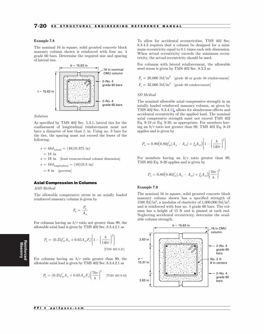
The nominal 16 in square, solid grouted concrete blockmasonry column shown is reinforced with four no. 4grade 60 bars. Determine the required size and spacingof lateral ties.
2–No. 4grade 60 bars
2–No. 4grade 60 bars
16 in nominalCMU column
b = 15.63 in
t = 15.63 in
Solution
As specified by TMS 402 Sec. 5.3.1, lateral ties for theconfinement of longitudinal reinforcement must nothave a diameter of less than 1
4 in. Using no. 3 bars forthe ties, the spacing must not exceed the lesser of thefollowing.
s d
ss d
48 (48)(0.375†in)
18†in16†in
16 (16)(0.5†in)
8†in
[least cross-sectional column dimension]
[governs]
lateral
longitudinal
= ==== =
=
Axial Compression in ColumnsASD Method
The allowable compressive stress in an axially loadedreinforced masonry column is given by
FPAa
a
n=
For columns having an h/r ratio not greater than 99, theallowable axial load is given by TMS 402 Sec. 8.3.4.2.1 as
P f A A Fh
r(0.25 0.65 ) 1
140
[TMS†402†8-21]
a m n st s
2
= +
For columns having an h/r ratio greater than 99, theallowable axial load is given by TMS 402 Sec. 8.3.4.2.1 as
P f A A Fr
h(0.25 0.65 )
70[TMS†402†8-22]a m n st s
2
= +
To allow for accidental eccentricities, TMS 402 Sec.8.3.4.3 requires that a column be designed for a mini-mum eccentricity equal to 0.1 times each side dimension.When actual eccentricity exceeds the minimum eccen-tricity, the actual eccentricity should be used.
For columns with lateral reinforcement, the allowablesteel stress is given by TMS 402 Sec. 8.3.3 as
F
F
20,000†lbf/in
32,000†lbf/in
[grade 40 or grade 50 reinforcement]
[grade 60 reinforcement]
s
s
2
2
=
=
SD Method
The nominal allowable axial compressive strength in anaxially loaded reinforced masonry column, as given byTMS 402 Sec. 9.3.4.11, allows for slenderness effects andaccidental eccentricity of the applied load. The nominalaxial compressive strength must not exceed TMS 402Eq. 9-19 or Eq. 9-20, as appropriate. For members hav-ing an h/r ratio not greater than 99, TMS 402 Eq. 9-19applies and is given by
( )P f A A f Ah
r0.80 0.80 ( ) 1
140n m n st y st
2
= +
For members having an h/r ratio greater than 99,TMS 402 Eq. 9-20 applies and is given by
( )P f A A f Ar
h0.80 0.80 ( )
70n m n st y st
2
= +
Example 7.9
The nominal 16 in square, solid grouted concrete blockmasonry column shown has a specified strength of1500 lbf/in2, a modulus of elasticity of 1,000,000 lbf/in2,and is reinforced with four no. 4 grade 60 bars. The col-umn has a height of 15 ft and is pinned at each end.Neglecting accidental eccentricity, determine the avail-able column strength.
b = 15.63 in16 in CMUcolumn
No. 3 @8 in centers
2.63 in
a =10.37 in
2.63 in
2–No. 4grade 60bars
2–No. 4grade 60 bars
7-207-20 S E S T R U C T U R A L E N G I N E E R I N G R E F E R E N C E M A N U A L

Rein
forced
Maso
nry
P P I • p p i 2 p a s s . c o m
Figure 7.6 Column Dimensions
A A
4b < h ≤ 99rmin
8 in ≤ t ≤ 3b
b ≥ 8 in
section A-A
in diameter minimum
2 bars minimum
2 bars minimum
s ≤ 16 × longitudinal bar diameter ≤ 48 × lateral tie diameter ≤ b
14
s2
s2
slab reinforcement
0.0025An ≤ As ≤ 0.04An∑
The design column strength is
P (0.9)(250†kips)
225†kipsn =
=
Combined Compression and FlexureASD Method
The allowable compressive stress in masonry due tocombined axial load and flexure is given by TMS 402Sec. 8.3.4.2.1 as
F f0.45b m=
In addition, the calculated compressive stress due to theaxial load cannot exceed the allowable values given inTMS 402 Sec. 8.2.4.1. For columns having an h/r rationot greater than 99, this is
F fh
r(0.25 ) 1.0
140[TMS†402†8-16]a m
2
=
For columns having an h/r ratio greater than 99, theallowable value is
F fr
h(0.25 )
70[TMS†402†8-17]a m
2
=
When the axial load on the column causes a compressivestress larger than the tensile stress produced by theapplied bending moment, the section is uncracked andstresses may be calculated by using the transformed sec-tion properties.3 To allow for creep in the masonry,6 thetransformed reinforcement area is taken as As(2n − 1),and the resultant stresses at the extreme fibers of thesection, as shown in Fig. 7.7, are given by
f f fPA
MS
m a b
t t
= ±
= ±
Stress in the reinforcement is equal to 2n times thestress in the adjacent masonry.
7-227-22 S E S T R U C T U R A L E N G I N E E R I N G R E F E R E N C E M A N U A L
Figure 7.7 Uncracked Section Properties
As
As(2n − 1) As(2n − 1)
applied forces
column section
transformedreinforcementarea
stress due toaxial load
stress due tobending moment
combined stress
As
P
M
PAt
+MSt
−MSt
− MSt
PAt
+ MSt
PAt

Rein
forced
Maso
nry
P P I • p p i 2 p a s s . c o m
The maximum flexural reinforcement ratio for specialreinforced masonry shear walls with M/(Vdv) ≥ 1.0 andwithP f A0.05 m n> is given by TMS 402 Eq. 8-23 as
nf
f nf
f2
m
yy
m
max =
+
SD Method
When flexural reinforcement is concentrated at the endsof a shear wall and axial loads are comparatively light,the shear wall may be designed in the same manner as abeam in bending. When these conditions are not valid,it is necessary to analyze the wall using basic principles.
To prevent brittle failure of a lightly reinforced shearwall, TMS 402 Sec. 9.3.4.2.2.2 requires the nominalflexural strength of the shear wall to be greater than 1.3times the nominal cracking moment strength. Therequired nominal moment is
M M1.3 cr
In order to provide adequate ductile response in a shearwall, TMS 402 Sec. 9.3.3.5.1 through TMS 402 Sec.9.3.3.5.4 limit the maximum reinforcement ratio inaccordance with a prescribed strain distribution. Themasonry compressive strain is defined as 0.0025 for con-crete masonry. The tensile strain, in the extreme tensionreinforcement, depends on the seismic design category,the shear wall type, the response modification factor, R,and the value of Mu/(Vdv). The tensile strain is limitedto the following values.
• 1.5s y= for R ≥ 1.5 andMu/(Vudv) ≤ 1.0
• s is not limited for R ≤ 1.5 andMu/(Vudv) ≤ 1.0
• 3.0s y= for an intermediate reinforced masonrywall withMu/(Vudv) ≥ 1.0
• 4.0s y= for a special reinforced masonry wall withMu/(Vudv) ≥ 1.0
The response modification factor, R, is defined inASCE/SEI75 Table 12.2-1. For masonry shear wallsused in bearing wall structural systems, the values of Rare given in Table 7.1.
The limit on maximum tensile reinforcement ratio forshear walls is waived if special boundary elements areprovided to the shear wall in compliance with TMS 402Sec. 9.3.6.5. Special boundary elements need not be pro-vided in shear walls meeting the following conditions.
The factored axial load does not exceed the valueP A f0.10u g m for geometrically symmetrical wall sec-
tions, or P A f0.05u g m for geometrically unsymmet-rical wall sections. In addition, one of the followingconditions must apply.
MV d
V A f
1.0
3M
V dwhen† 3.0
u
u v
u n mu
u v
Table 7.1 Response Modification Factor
masonry shear wall type R
special reinforced 5.0
intermediate reinforced 3.5special reinforced 5.0
ordinary reinforced 2.0
detailed plain 2.0
ordinary plain 1.5
Example 7.12
The nominal 8 in solid grouted concrete block masonryshear wall shown in the illustration has a specifiedstrength of 1500 lbf/in2 and a modulus of elasticity of1,000,000 lbf/in2. An in-plane wind load of 32 kips actsat the top of the wall, as shown, and this is the govern-ing shear load. The wall is located in a structureassigned to seismic design category C and is laid in run-ning bond. Determine the reinforcement required in thewall. Axial load may be neglected.
W = 32 kips
h = 15 ft
dv = 15 ft
Solution
ASD Method
The wall is located in seismic design category C. Anordinary reinforced masonry wall may be used sinceh 160†ft< .
7-307-30 S E S T R U C T U R A L E N G I N E E R I N G R E F E R E N C E M A N U A L
Reinforced
Masonry
P P I • p p i 2 p a s s . c o m
The allowable stresses, in accordance with TMS 402Sec. 8.3.3 and Sec. 8.3.4.2.2, are
F f
F
0.45
(0.45) 1500†lbf
in
675†lbf/in
32,000†lbf/in
b m
s
2
2
2
=
=
=
=
Using IBC Eq. 16-15, the factored load is
V W0.6(0.6)(32†kips)
19.2†kips
===
The bending moment, produced by the wind load, atthe base of the wall is
M Vh(19.2†kips)(15†ft)
288†ft-kips
===
Use Mu/(Vdv) = 1.0 per TMS 402 Comm. Sec. 8.3.5.1.2.Assuming that two no. 6 reinforcing bars are located4 in from each end of the wall, the relevant parametersof the wall are
( )b
d
A
nEE
Abd
n
7.63†in
(15†ft) 12†inft
4†in 176†in
(2)(0.44†in ) 0.88†in
29,000,000†lbf
in
1,000,000†lbf
in29
0.88†in(7.63†in)(176†in)
0.000655(0.000655)(29)
0.0190
s
s
m
s
2 2
2
2
2
=
= =
= =
=
=
=
=
=
===
From App. 2.B, the wall stresses caused by the windload, in accordance with TMS 402 Sec. 7.3.2, are
( )
k n n n
jk
fM
jkbd
2 ( )
(2)(0.0190) (0.0190) 0.0190
0.177
13
10.177
30.9412
(2)(288†ft-kips) 12†inft
1000†lbfkip
(0.941)(0.177)(7.63†in)(176†in)
176†lbf/in
675†lbf/in [satisfactory]
b
2
2
2
2
2
2
= +
= +
=
=
=
=
=
=
=
<
( )
fM
jdA
(288†ft-kips) 12†inft
1000†lbfkip
(0.941)(176†in)(0.88†in )
23,713†lbf/in
32,000†lbf/in [satisfactory]
ss
2
2
2
=
=
=
<
The flexural reinforcement provided is adequate.
The shear stress in the masonry wall is given byTMS 402 Eq. 8-24 as
( )f
VA
(19.2†kips) 1000†lbfkip
(7.63†in)(15†ft) 12†inft
14†lbf/in
vnv
2
= =
=
The allowable stress is obtained by applying TMS 402Sec. 8.3.5.1.3.
7-31R E I N F O R C E D M A S O N R Y D E S I G N 7-31
Rein
forced
Maso
nry
P P I • p p i 2 p a s s . c o m
The allowable shear stress in an ordinary reinforcedshear wall without shear reinforcement is given byTMS 402 Eq. 8-29 as
( )
FMVd
fPA
f
4.0 1.75 0.25
12
4.0 (1.75)(1.0) 1500†lbf
in0†
lbf
in
43.6†lbf/in
14†lbf/in [satisfactory]
vm mn
v
1
2
2 2
2
2
= +
= +
=
> =
Masonry takes all the shear force, and nominal rein-forcement is required as described in TMS 402Sec. 7.3.8.1.
SD Method
The structure is assigned to seismic design category Cand an ordinary reinforced masonry wall may be usedsince h < 100 ft.
Using IBC Eq. 16-6, the factored load is
V W1.0
(1.0)(32†kips)
32†kips
u ===
The bending moment produced by the wind load at thebase of the wall is
M V h(32†kips)(15†ft)
480†kips-ft
u u===
Assuming two no. 6 reinforcing bars are located 4 infrom each end of the wall, the relevant parameters of thewall are
( )b
d
A
7.63†in
(15†ft) 12†inft
4†in 176†in
(2)(0.44†in ) 0.88†ins2 2
=
= =
= =
The stress block depth is
aA f
bf0.80
(0.88†in ) 60†kips
in1000†
lbfkip
(0.80)(7.63†in) 1500†lbf
in5.77†in
s y
m
22
2
=
=
=
The nominal strength is
( )M A f da2
(0.88†in ) 60†kips
in176†in
5.77†in2
12†inft
762†ft-kips
n s y
22
=
=
=
The design strength is
M
M
(0.9)(762†ft-kips)
686†ft-kips[satisfactory]
n
u
==>
The flexural reinforcement provided is adequate.
TMS 402 Comm. Sec. 9.3.4.1.2 permits the adoption ofMu/Vudv= 1.0. The nominal shear strength of a shearwall without shear reinforcement is given by TMS 402Eq. 9-24. Since Pu= 0 lbf,
( )( )
VM
V dA f P
V
V
4.0 1.75 0.25
4.0 (1.75)(1.0) (7.63†in)(15†ft)
1500†lbf
in12†
inft
0†lbf
1000†lbfkip
120†kips
(0.8)(120†kips)
96†kips32†kips [satisfactory]
nmu
u vnv m u
nm
u
2
= +
=× +
===> =
The masonry takes all the shear force, and nominal rein-forcement is required as detailed in TMS 402Sec. 7.3.8.1.
8. DESIGN OF SLENDERWALLS........................................................................................................................
Nomenclature
a depth of equivalent rectangular stress block in
Ag gross cross-sectional area of member in2
Amax maximum area of reinforcement that willsatisfy TMS 402 Sec. 9.3.3.5.1
in2
An net cross-sectional area of member in2
As cross-sectional area of reinforcing steel in2
Ase equivalent area of reinforcing steel in2
b width of section in
7-327-32 S E S T R U C T U R A L E N G I N E E R I N G R E F E R E N C E M A N U A L
Reinforced
Masonry
P P I • p p i 2 p a s s . c o m
The applied strength level moment at midheight of thewall is given by TMS 402 Eq. 9-30 as
( )
Mw h P e
P
MM
8 2
†
0.03†kip
ft(20†ft)
8
(0.36†kip)(7.5†in)
(2) 12†inft
†(1.04†kips)(0.20†in)
12†inft
† 1.63†ft-kips†
†
[satisfactory]
[TMS†402 Eq. 9-30 applies]
uu uf u
u u
n
cr
1
2
1
2
= + +
= +
+
=<<
The deflection corresponding to the factored moment isdetermined in accordance with TMS 402 Sec. 9.3.5.4.2.The moment of inertia of the net wall section is
( )I
bt12
†(1†ft)(7.63†in) 12†
inft
12† 444†in
n
3
3
4
=
=
=
The modulus of elasticity of reinforcement is given byTMS 402 Sec. 4.2.2.1 as
E 29,000†kips/ins2=
The modulus of elasticity of concrete masonry is givenby TMS 402 Sec. 4.2.2.2.1 as
E f900
† (900)1500†
lbf
in
1000†lbfkip
† 1350†kips/in
m m
2
2
=
=
=
The modular ratio is
nEE
29,000†kips
in
1350†kips
in21.5
s
m
2
2
= =
=
The distance from the extreme compression fiber to theneutral axis is given by TMS 402 Eq. 9-35 as
cA f P
f b0.64
(0.15†in ) 60†kips
in1.04†kips 1000†
lbfkip
(0.64) 1500†lbf
in(12†in)
0.87†in
s y u
m
22
2
=+
=
+
=
Allowing for the axial load, the moment of inertia of thecracked transformed section about the neutral axis isgiven by TMS 402 Eq. 9-34 as
( )
Ibc
n APf
d c3
( )
†(1†ft)(0.87†in) 12†
inft
3
† (21.5) 0.15†in1.04†kips
60†kips
in
†7.63†in
20.87†in
† 33.8†in
cr su
y
32
3
2
2
2
4
= + +
=
+ +
×
=
Since M Mu cr1 < , the midheight deflection correspond-ing to the factored moment is derived from TMS 402Eq. 9-29 as
( ) ( )
M hE I
5
48
†
(5)(1.69†ft-kips) 12†inft
(20†ft) 12†inft
(48) 1350†kips
in(444†in )
† 0.203†in
†This is approximately equal to
the assumed deflection; further
iterations are unnecessary.
ucr
m n
2
2
24
=
=
=
So,
MM
1.63†ft-kips
[satisfactory]u
n
=<
The flexural capacity is adequate.
7-39R E I N F O R C E D M A S O N R Y D E S I G N 7-39

Reinforced
Masonry
P P I • p p i 2 p a s s . c o m
Example 7.19
As given in Ex. 7.17, a glulam crosstie between dia-phragm chords is supported at one end in a steel beambucket. The bucket is attached to a solid grouted con-crete block masonry wall with a masonry compressivestrength of 1500 lbf/in2. The four headed anchor boltsare †in3
4 diameter ASTM A 307 type C, with a mini-mum specified yield strength of 36 kips/in2 and an effec-tive cross-sectional area of 0.334 in2. The effectiveembedment length of the anchor bolts is 6 in, and thethreaded portion of the bolts is not located within theshear plane. The ASD governing load combination givesa tension force on the beam bucket of T = 13 kips and ashear force ofV 1.5†kips= . The SD governing load com-bination gives a tension force of T 21.7†kipsu = and ashear force ofV 2.25†kipsu = . Determine if the bolts areadequate for the combined tension and shear forces.
Solution
The applied tension force on one bolt is
bT413†kips
43.25†kips
a =
=
=
The applied shear force on one bolt is
bV41.5†kips
40.38†kip
v =
=
=
For combined tension and shear, TMS 402 Eq. 8-10must be satisfied.
bB
bB
1
3.25†kips
5.25†kips
0.38†kip
1.66†kips0.85
† 1 [satisfactory]
a
a
v
v+
+ =
<
SD Method
The factored tension force on one bolt is
bT421.7†kips
45.43†kips
afu=
=
=
The factored shear force on one bolt is
bV42.25†kips
40.56†kips
vfu=
=
=
For combined tension and shear, anchor bolts must com-ply with TMS 402 Eq. 9-10, which is
b
B
b
B1
5.43†kips
8.41†kips
0.56†kip
2.48†kips0.87
1 [satisfactory]
af
an
vf
vn+
+ =
<
10. DESIGN OF PRESTRESSEDMASONRY........................................................................................................................
Nomenclature
An net cross-sectional area of masonry in2
Aps area of prestressing steel in2
As area of nonprestressed reinforcement in2
b width of section inCm force in masonry stress block lbf
d distance from extreme compression fiberto centroid of prestressing tendon orreinforcement
in
D dead load or related internal moments orforces
lbf
e eccentricity of axial load in
Em modulus of elasticity of masonry lbf/in2
Emi modulus of elasticity of masonry attransfer
lbf/in2
Eps modulus of elasticity of prestressing steel lbf/in2
fa calculated compressive stress in masonrydue to axial load
lbf/in2
fai calculated compressive stress in masonryat transfer due to axial load
lbf/in2
fb calculated compressive stress in masonrydue to flexure
lbf/in2
fbi calculated compressive stress in masonryat transfer due to flexure
lbf/in2
fmspecified compressive strength of masonry lbf/in2
fmispecified compressive strength of masonryat time of prestress transfer
lbf/in2
fpj stress in prestressing tendon due tojacking force
lbf/in2
fps stress in prestressing tendon at nominalstrength
lbf/in2
fpsi initial stress in prestressing tendon lbf/in2
7-49R E I N F O R C E D M A S O N R Y D E S I G N 7-49
Rein
forced
Maso
nry
P P I • p p i 2 p a s s . c o m
For a centrally located, laterally restrained or unre-strained, unbonded prestressing tendon, the stress inthe tendon at nominal load has been determined empiri-cally, and it is given by TMS 402 Eq. 10-3 as
f fE d
l
A fP
f bd
ff
0.03 1 1.56
†
†
ps seps
p
ps psu
m
se
py
= ++
The force in the prestressing tendon at nominal load is
P f Aps ps ps=
A rectangular compression stress block is assumed inthe face shell on the compression face of the wall with amagnitude of f0.80 m and a depth of a. The compressionforce on the stress block acts at mid-depth of the stressblock and is given by
C abf0.80m m=
Stress in the face shell on the tension face of the wall isignored. Allowing for the factored axial load, Pu, on thewall, the depth of the stress block is obtained by equat-ing forces on the section to give
af A
P
f b0.80
ps psu
m
=+
When the wall also contains concentrically placed,bonded, nonprestressed reinforcement in grouted cores,the depth of the stress block is given by TMS 402Eq. 10-1 as
af A f A
P
f b0.80
ps ps y su
m
=+ +
The nominal flexural capacity of the section is obtainedby taking moments about the line of action of the com-pression force to give TMS 402 Eq. 10-2 which is
( )M f A f AP
da2n ps ps y s
u= + +
The design flexural capacity is given by TMS 402Sec. 10.4.3.3 as
M M0.8n n=
To ensure a ductile failure in concrete block walls sub-ject to out-of-plane loading, TMS 402 Sec. 10.4.3.6 spec-ifies a maximum depth for the stress block of
a d0.36=
In addition, the depth of the stress block may not exceedthe thickness of the face shell.
Example 7.22
The nominal 8 in ungrouted concrete block masonry walldescribed in Ex. 7.20 has face-shell mortar bedding oftype S portland cement/lime mortar, a specified strengthof f 2500†lbf/inm
2= at 28 days, and a specified strength
of fmi = 2000 lbf/in2 at transfer. The wall is post-tensionedwith †in7
16 diameter steel rods at 16 in centers placed cen-trally in the wall, and the rods are laterally restrained.The wall has an effective height of h = 20 ft and is simplysupported at the top and bottom. The roof live load is200 lbf/ft, and the roof dead load is 400 lbf/ft applied tothe wall without eccentricity. The masonry wall has aweight of γw = 37 lbf/in2. The properties of the steel rodare Eps = 29,000 kips/in2, Aps = 0.142 in2, fpy = 100 kips/in2, fpu = 122 kips/in2. Wind load governs and has a valueof w = 25 lbf/ft2. Assume the loss of prestress at transfer is5% and the final loss of prestress is 30%. Determine if thewall design flexural capacity is adequate. Ignore P-deltaeffects.
Solution
The following calculations are based on a 1 ft length ofwall and on information obtained from Ex. 7.20 andEx. 7.21.
The weight of the wall above midheight plus the roofdead load is
P 770†lbf=
In determining the moment demand on the wall, thegoverning load combination is IBC Eq. 16-6, which is
Q D W0.9 1.0u = +
The factored axial load on the wall is
P P0.9 (0.9)(770†lbf) 693†lbfu = = =
7-587-58 S E S T R U C T U R A L E N G I N E E R I N G R E F E R E N C E M A N U A L
LateralF
orces
P P I • p p i 2 p a s s . c o m
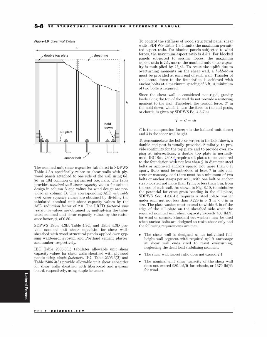
Figure 8.9 Shear Wall Details
sheathing
hold-down
sill plate
anchor bolt
L
h
double top plate
The nominal unit shear capacities tabulated in SDPWSTable 4.3A specifically relate to shear walls with ply-wood panels attached to one side of the wall using 6d,8d, or 10d common or galvanized box nails. The tableprovides nominal unit shear capacity values for seismicdesign in column A and values for wind design are pro-vided in column B. The corresponding ASD allowableunit shear capacity values are obtained by dividing thetabulated nominal unit shear capacity values by theASD reduction factor of 2.0. The LRFD factored unitresistance values are obtained by multiplying the tabu-lated nominal unit shear capacity values by the resist-ance factor, φ, of 0.80.
SDPWS Table 4.3B, Table 4.3C, and Table 4.3D pro-vide nominal unit shear capacities for shear wallssheathed with wood structural panels applied over gyp-sum wallboard; gypsum and Portland cement plaster;and lumber, respectively.
IBC Table 2306.3(1) tabulates allowable unit shearcapacity values for shear walls sheathed with plywoodpanels using staple fasteners. IBC Table 2306.3(2) andTable 2306.3(3) provide allowable unit shear capacitiesfor shear walls sheathed with fiberboard and gypsumboard, respectively, using staple fasteners.
To control the stiffness of wood structural panel shearwalls, SDPWS Table 4.3.4 limits the maximum permit-ted aspect ratio. For blocked panels subjected to windforces, the maximum aspect ratio is 3.5:1. For blockedpanels subjected to seismic forces, the maximumaspect ratio is 2:1, unless the nominal unit shear capac-ity is multiplied by b h2 /s . To resist the uplift due tooverturning moments on the shear wall, a hold-downmust be provided at each end of each wall. Transfer ofthe lateral force to the foundation is achieved withanchor bolts at a maximum spacing of 6 ft. A minimumof two bolts is required.
Since the shear wall is considered non-rigid, gravityloads along the top of the wall do not provide a restoringmoment to the wall. Therefore, the tension force, T, inthe hold-down, which is also the force in the end posts,or chords, is given by SDPWS Eq. 4.3-7 as
T C vh= =
C is the compression force; v is the induced unit shear;and h is the shear wall height.
To accommodate the bolts or screws in the hold-down, adouble end post is usually provided. Similarly, to pro-vide continuity for the top plate and to provide overlap-ping at intersections, a double top plate is normallyused. IBC Sec. 2308.6 requires sill plates to be anchoredto the foundation with not less than 1
2 in diameter steelbolts or approved anchors spaced not more than 6 ftapart. Bolts must be embedded at least 7 in into con-crete or masonry, and there must be a minimum of twobolts or anchor straps per wall, with one bolt or anchorstrap located not more than 12 in, or less than 4 in, fromthe end of each wall. As shown in Fig. 8.10, to minimizethe potential for cross grain bending in the sill plate,SDPWS Sec. 4.3.6.4.3 requires a steel plate washerunder each nut not less than 0.229 in × 3 in × 3 in insize. The plate washer must extend to within 1
2 in of theedge of the sill plate on the sheathed side when therequired nominal unit shear capacity exceeds 400 lbf/ftfor wind or seismic. Standard cut washers may be usedwhen anchor bolts are designed to resist shear only andthe following requirements are met.
• The shear wall is designed as an individual full-height wall segment with required uplift anchorageat shear wall ends sized to resist overturning,neglecting the dead load stabilizing moment.
• The shear wall aspect ratio does not exceed 2:1.
• The nominal unit shear capacity of the shear walldoes not exceed 980 lbf/ft for seismic, or 1370 lbf/ftfor wind.
8-88-8 S E S T R U C T U R A L E N G I N E E R I N G R E F E R E N C E M A N U A L

LateralF
orces
P P I • p p i 2 p a s s . c o m
L = 8 ft
h = 8 ft
V = 11,600 lbf
C
T
4.25 in 4.5 ina = 7.25 ft
SDPWS Eq. 4.3-7 may be used to obtain the hold-downforce. This ignores the vertical load on the wall and thedistance of the hold-down anchor rod from the end ofthe wall. SDPWS Eq. 4.3-7 gives the hold-down force as
T v h 870†lbfft
(8†ft) 6960†lbf= = =
The allowable parallel-to-grain load,Z , on a 58 in diam-
eter bolt in the 212 in thick Douglas fir-larch sill plate is
obtained from NDS16 Table 11E as
Z 1180†lbf=
The load duration factor,CD, for wind load is given byNDS Table 2.3.2 as
C 1.6D =
Therefore, the number, N, of 58 in diameter anchor bolts
required is
NV
C Z0.6 (0.6)(11,600†lbf)
(1.6)(1180†lbf)
† 3.69 [use 4 bolts]
D= =
=
Shear Walls with OpeningsA shear wall with openings has been designed tradition-ally by considering each full height segment of the wallas an individual shear wall. As shown in Fig. 8.11, thisresults in a wall with a single opening being designed astwo separate shear walls requiring a total of four hold-downs, one at either end of the two shear walls. Sheath-ing above and below the opening is not considered tocontribute to the overall shear capacity of the wall, andthe shear capacity of the wall is calculated as the sum ofthe capacities of the individual segments.
Figure 8.11 Segmented Shear Wall
shear wallsegment opening
V
An alternative design method is the perforated shearwall method.17 The shear capacity of a perforated shearwall is calculated as a percentage of the capacity of thewall without openings, and the method is specified inSDPWS Sec. 4.3.3.5. As shown in Fig. 8.12, the advant-age of the method is that only two hold-downs are neces-sary, one at either end of the wall. Sheathed areas aboveand below openings are not designed for force transferand are considered to provide only local restraint attheir ends. The shear capacity of a perforated walldepends on the maximum opening height and on thepercentage of full height sheathing.
Figure 8.12 Perforated Shear Wall
V
Lo
hho
L
SDPWS Sec. 4.3.5.3 requires the following for perfo-rated walls.
• A segment without openings must be located at eachend of the perforated shear wall.
• The aspect ratio limitations of SDPWS Sec. 4.3.4.1apply.
• The required nominal unit shear capacity for a singlesided wall is limited to a maximum of 1740 lbf/ft forseismic or 2435 lbf/ft for wind.
• Where out-of-plane offsets occur, portions of the wallon each side of the offset must be considered separateperforated shear walls.
• Collectors for shear transfer must be providedthrough the full length of the wall.
• A perforated shear wall must have uniform top-of-wall and bottom-of-wall elevations.
• The height must not exceed 20 ft.
8-108-10 S E S T R U C T U R A L E N G I N E E R I N G R E F E R E N C E M A N U A L

LateralForces
P P I • p p i 2 p a s s . c o m
The design shear capacity, V, of a perforated shear wall is
V vC Lo i=
The variables are defined as
v = allowable unit shear capacity in a segmentedshear wall (lbf/ft)
Co = shear capacity adjustment factor given inSDPWS Table 4.3.3.5
Li = sum of perforated shear wall segment lengths(ft)
Values ofCo are given in Table 8.1.
Table 8.1 Capacity Adjustment Factors
wall height, hj
maximum opening heightj
h/3j h/2j 2h/3j 5h/6j hj
8 -0 wall 2 -8 4 -0 5 -4 6 -8 8 -0
10 -0 wall 3 -4 5 -0 6 -8 8 -4 10 -0full-height sheathing
(%) shear capacity adjustment factorj10 1.00 0.69 0.53 0.43 0.3620 1.00 0.71 0.56 0.45 0.3840 1.00 0.77 0.63 0.53 0.4560 1.00 0.83 0.71 0.63 0.5680 1.00 0.91 0.83 0.77 0.71100 1.00 1.00 1.00 1.00 1.00
Adapted with permission from Special Design Provisions for Windand Seismic with Commentary, copyright © 2015, by the AmericanWood Council.
The force in a hold-down, which is also the force in theend posts, is given by SDPWS Eq. 4.3-8 as
T CVh
C Lo i
=
=
The unit shear force in a perforated shear wall is givenby SDPWS Eq. 4.3-9 as
vV
C Lo imax =
Anchor bolts, in addition to resisting the horizontalshear force v Limax , must also resist a uniformly dis-tributed uplift force. This force is given by SDPWSSec. 4.3.6.4.2.1 as
t vmax=
Example 8.4
The perforated shear wall shown in Fig. 8.12 has anoverall length, L, of 24 ft and a height, h, of 8 ft. Thesheathing is 15
32 in Structural I and the stud spacing is16 in. The centrally placed opening has dimensions ofL 8†fto = and h 4†fto = . The dead load on the wall fromthe roof diaphragm is w 80†lbf/ft= , and the strengthlevel wind load transmitted by the diaphragm isV 11.6†kips= . Determine the nailing requirements forthe shear wall, the force in the hold-downs, and thenumber of 5
8 in diameter anchor bolts required in the4 in × 3 in Douglas fir-larch sill plate. Neglect the self-weight of the shear wall.
Solution
The aspect ratio of each segment is
aL L
h224†ft 8†ft(2)(8†ft)
1.0 [complies with SDPWS Table 4.3.4]
o=
=
=
The percentage of full height sheathing is
LL
8†ft 8†ft24
100%
67%
i =+
×
=
The maximum opening height ratio is
hh
4†ft8†ft0.5
o =
=
From SDPWS Table 4.3.3.5, the shear capacity adjust-ment factor is
C 0.86o =
The strength level unit shear acting on the shear wall is
vV
L L
(11.6†kips) 1000†lbfkip
24†ft 8†ft725†lbf/ft
o=
=
=
8-11L A T E R A L F O R C E S 8-11
LateralF
orces
P P I • p p i 2 p a s s . c o m
Allowing for the shear capacity adjustment factor, theequivalent unit shear for a perforated shear wall is
vvC
725†lbfft
0.86843†lbf/ft
o=
=
=
The required spacing of 10d common nails with 112 in
penetration is obtained from SDPWS Table 4.3A as
all panel edges 4 in
intermediate framingmembers
12 in
capacity provided (0.8)(1430 lbf/ft) = 1144 lbf/ft
capacity required 843 lbf/ft [satisfactory]
The allowable parallel-to-grain load on a 58 in diameter
bolt in the 212 in thick Douglas fir-larch sill plate is
obtained from NDS Table 11E as
Z 1180†lbf|| =
The load duration factor for wind load is given by NDSTable 2.3.2 as
C 1.6D =
Converting to service level values using IBC Eq. 16-15,the number of 5
8 in diameter bolts required is
NV
C Z0.6
(0.6)(11.6†kips) 1000†lbfkip
(1.6)(1180†lbf)
3.7 †[use†4 bolts]
D=
=
=
Two bolts in each segment must be provided. Thestrength level shear force on each bolt is
PV4
(11.6†kips) 1000†lbfkip
4†bolts2900†lbf/bolt
v =
=
=
The available strength level shear force on a 58 in diame-
ter A307 bolt is given by AISC Manual18 Table 7-1 as
rP6230†lbf
[satisfactory]n
v
=>
The uniformly distributed design uplift anchorage forceon the sill plate of each full height, perforated shear wallsegment is given by SDPWS Sec. 4.3.6.4.2.1 as
t vV
C L
(11.6†kips) 1000†lbfkip
(0.86)(8†ft 8†ft)
843†lbf/ft
o i
max=
=
=+
=
The net uplift on the shear wall is given by IBCEq. 16-6 as
u w t0.9
(0.9) 80†lbfft
843†lbfft
771†lbf/ft
= +
= +
=
The strength level tensile force in each bolt is
Pu L4†bolts
771†lbfft
(8†ft 8†ft)
4†bolts3084†lbf/bolt
ti= =
+
=
The available strength tensile force on a 58 in diameter
A307 bolt is given by AISC Manual Table 7-2 as
rP10,400†lbf
[satisfactory]n
t
=>
The anchor bolts provided are adequate for both shearand uplift. The force in a hold-down is given by SDPWSEq. 4.3-8 as
T CVh
C Lv h
843†lbfft
(8†ft)
6744†lbf
4046†lbf
[at strength level]
[at service level]
o i
max
=
=
=
=
==
8-128-12 S E S T R U C T U R A L E N G I N E E R I N G R E F E R E N C E M A N U A L
LateralForces
P P I • p p i 2 p a s s . c o m
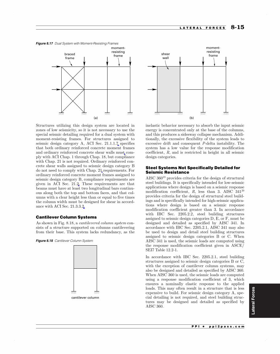
Structures utilizing this design system are located inzones of low seismicity, so it is not necessary to use thespecial seismic detailing required for a dual system withmoment-resisting frames. For structures assigned toseismic design category A, ACI Sec. 21.1.1.7 specifiesthat both ordinary reinforced concrete moment framesand ordinary reinforced concrete shear walls must com-ply with ACI Chap. 1 through Chap. 18, but compliancewith Chap. 21 is not required. Ordinary reinforced con-crete shear walls assigned to seismic design category Bdo not need to comply with Chap. 21 requirements. Forordinary reinforced concrete moment frames assigned toseismic design category B, compliance requirements aregiven in ACI Sec. 21.2. These requirements are thatbeams must have at least two longitudinal bars continu-ous along both the top and bottom faces, and that col-umns with a clear height less than or equal to five timesthe column width must be designed for shear in accord-ance with ACI Sec. 21.3.3.2.
Cantilever Column SystemsAs shown in Fig. 8.18, a cantilevered column system con-sists of a structure supported on columns cantileveringfrom their base. This system lacks redundancy, as the
Figure 8.18 Cantilever Column System
cantilever column
inelastic behavior necessary to absorb the input seismicenergy is concentrated only at the base of the columns,and this produces a sidesway collapse mechanism. Addi-tionally, the excessive flexibility of the system leads toexcessive drift and consequent P-delta instability. Thesystem has a low value for the response modificationcoefficient, R, and is restricted in height in all seismicdesign categories.
Steel Systems Not Specifically Detailed forSeismic ResistanceAISC 36019 provides criteria for the design of structuralsteel buildings. It is specifically intended for low-seismicapplications where design is based on a seismic responsemodification coefficient, R, less than 3. AISC 34120
provides criteria for the design of structural steel build-ings and is specifically intended for high-seismic applica-tions where design is based on a seismic responsemodification coefficient greater than 3. In accordancewith IBC Sec. 2205.2.2, steel building structuresassigned to seismic design categories D, E, or F, must bedesigned and detailed as specified by AISC 341. Inaccordance with IBC Sec. 2205.2.1, AISC 341 may alsobe used to design and detail steel building structuresassigned to seismic design categories B or C. WhenAISC 341 is used, the seismic loads are computed usingthe response modification coefficient given in ASCE/SEI7 Table 12.2-1.
In accordance with IBC Sec. 2205.2.1, steel buildingstructures assigned to seismic design categories B or C,with the exception of cantilever column systems, mayalso be designed and detailed as specified by AISC 360.When AISC 360 is used, the seismic loads are computedusing a response modification coefficient of 3, whichensures a nominally elastic response to the appliedloads. This may often result in a structure that is lessexpensive to build. For seismic design category A, spe-cial detailing is not required, and steel building struc-tures may be designed and detailed as specified byAISC 360.
8-15L A T E R A L F O R C E S 8-15
Figure 8.17 Dual System with Moment-Resisting Frames
bracedframe
(a) (b)
moment-resistingframe shear
wall
moment-resistingframe

LateralF
orces
P P I • p p i 2 p a s s . c o m
Table 8.8 Maximum Allowable Story Drift, Δa
j risk categoryj
building typej I or IIj IIIj IVj
one-story buildings withfittings designed toaccomodate driftj no limitj no limitj no limitj
buildings other thanmasonry buildings offour stories or less withfittings designed toaccommodate driftj 0.025hsxj 0.020hsxj 0.015hsxj
masonry cantilevershear wall buildingsj 0.010hsxj 0.010hsxj 0.010hsxj
other masonry shearwall buildingsj 0.007hsxj 0.007hsxj 0.007hsxj
all other buildingsj 0.020hsxj 0.015hsxj 0.010hsxj
To allow for inelastic deformations, drift is determinedby using the deflection amplification factor Cd definedin Table 8.6. The amplified deflection at level x is givenby ASCE/SEI7 Eq. 12.8-15 as
CIxd xe
e=
The term δxe represents the horizontal deflection at levelx, determined by an elastic analysis using the code-pre-scribed design level forces. In accordance with ASCE/SEI7 Sec. 12.8.7, P-delta effects need not be included inthe calculation of drift when the stability coefficient θdoes not exceed 0.10.
Using the nomenclature from Fig. 8.24, the elastic lat-eral displacement in the bottom story is
F F F Fse
n1
3 2 1
1=
+ + +
The elastic lateral displacement in the second story is
F F Fse
ne2
3 2
21=
+ ++
The elastic lateral displacement in the third story is
F Fse
ne3
3
32=
++
The elastic lateral displacement in the top story is
Fsne
n
ne3= +
The drift in the bottom story is
CId e
e1
1=
The drift in the second story is
CI
( )d e e
e2
2 1=
The drift in the third story is
CI
( )d e e
e3
3 2=
The drift in the top story is
CI
( )n
d ne e
e
3=
For the calculation of drift, in accordance with ASCE/SEI7 Sec. 12.8.6.2, the full value of T, the fundamentalperiod determined by using the Rayleigh procedure,may be used to determine the seismic base shear.
Example 8.17
Determine the drift in the bottom story of the two-story, reinforced concrete, moment-resisting frame ofEx. 8.15, which is used as a residential building. The rel-evant details are shown. Fittings are designed to accom-modate drift.
W2 = 400 kipsF2 =79 kips
s2 = 400 kips/in
W1 = 1100 kipsF1 =109 kips
s1 = 500 kips/in
188 kips
hs2 = 15 ft
hs1 = 15 ft
Solution
From Ex. 8.12, the fundamental period obtained byusing the Rayleigh procedure is
T 0.567†sec=
8-348-34 S E S T R U C T U R A L E N G I N E E R I N G R E F E R E N C E M A N U A L

LateralForces
P P I • p p i 2 p a s s . c o m
Example 8.21
Determine the vertical force distribution by using thesimplified procedure for the two-story, reinforced con-crete, bearing wall structure of Ex. 8.20.
Solution
From Ex. 8.20, the following values are obtained.
VW
98.6†kips400†kips
==
The forces at each level are determined from ASCE/SEI7 Eq. 12.14-12 as
Fw VWw
w
(98.6†kips)
400†kips0.25
xx
x
x
=
=
=
The values of Fx are given in the following table.
leveljWx
(kips)jFx
(kips)j
2 150 37.01 250 61.6total 400 98.6
Simplified Determination of DriftIn accordance with ASCE/SEI7 Sec. 12.14.8.5, whenthe simplified procedure is used to determine the seismicbase shear, the design story drift in any story must betaken as
h0.01x sx=
Example 8.22
Using the simplified procedure, determine the drift inthe bottom story of the two-story, reinforced concrete,bearing wall structure of Ex. 8.20.
Solution
The design story drift in the bottom story is given by
( )h0.01
(0.01)(15†ft) 12†inft
1.80†in
s1 1=
=
=
11. SEISMIC LOAD ON AN ELEMENT OF ASTRUCTURE........................................................................................................................
The seismic load, E, is a function of both horizontal andvertical earthquake-induced forces and is given byASCE/SEI7 Sec. 12.4.2 as
E Q S D0.2E DS= +
The term QE is the lateral force produced by the calcu-lated base shear V. The term 0.2SDSD is the verticalforce due to the effects of vertical acceleration. Theredundancy factor, ρ, is a factor that penalizes struc-tures with relatively few lateral load-resisting elementsand is defined by ASCE/SEI7 Sec. 12.3.4.
The seismic performance of a structure is enhanced byproviding multiple lateral load-resisting elements.Therefore, the yield of one element will not result in anunstable condition that may lead to collapse of thestructure. For this situation, the value of the redun-dancy factor is ρ= 1.0. When the yield of an elementwill result in an unstable condition, the value of theredundancy factor is ρ= 1.3.
In accordance with ASCE/SEI7 Sec. 12.3.4.1, the valueof the redundancy factor is equal to 1.0 for thefollowing.
• structures assigned to seismic design categories Band C
• drift calculations and P-delta effects
• design of nonstructural components
• design of nonbuilding structures that are not similarto buildings
• design of collector elements, splices, and their con-nections for which load combinations with over-strength factors are used
• design of members and connections for which load-combinations with overstrength factors are required
• diaphragm loads that are determined using ASCE/SEI7 Eq. 12.10-1
• structures with damping systems designed in accord-ance with ASCE/SEI7 Chap. 18
For structures assigned to seismic design categories D,E, and F, 1.3= unless the requirements of ASCE/SEI7 Sec. 12.3.4.2a or Sec. 12.3.4.2b are met.
In accordance with ASCE/SEI7 Sec. 12.3.4.2a, thevalue of the redundancy factor may be taken equal to1.0, provided that each story resisting more than 35% ofthe base shear complies with the following.
• For a braced frame, the removal of an individualbrace, or connection thereto, does not result in morethan a 33% reduction in story strength, nor create an
8-41L A T E R A L F O R C E S 8-41
LateralForces
P P I • p p i 2 p a s s . c o m
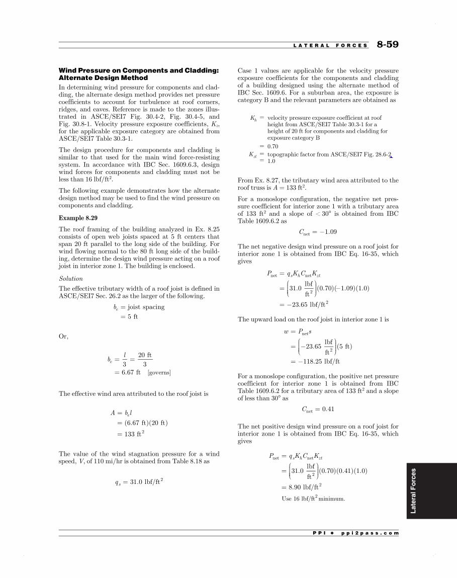
Wind Pressure on Components and Cladding:Alternate Design MethodIn determining wind pressure for components and clad-ding, the alternate design method provides net pressurecoefficients to account for turbulence at roof corners,ridges, and eaves. Reference is made to the zones illus-trated in ASCE/SEI7 Fig. 30.4-2, Fig. 30.4-5, andFig. 30.8-1. Velocity pressure exposure coefficients, Kz,for the applicable exposure category are obtained fromASCE/SEI7 Table 30.3-1.
The design procedure for components and cladding issimilar to that used for the main wind force-resistingsystem. In accordance with IBC Sec. 1609.6.3, designwind forces for components and cladding must not beless than 16 lbf/ft2.
The following example demonstrates how the alternatedesign method may be used to find the wind pressure oncomponents and cladding.
Example 8.29
The roof framing of the building analyzed in Ex. 8.25consists of open web joists spaced at 5 ft centers thatspan 20 ft parallel to the long side of the building. Forwind flowing normal to the 80 ft long side of the build-ing, determine the design wind pressure acting on a roofjoist in interior zone 1. The building is enclosed.
Solution
The effective tributary width of a roof joist is defined inASCE/SEI7 Sec. 26.2 as the larger of the following.
b joist spacing
† 5†fte =
=
Or,
bl3
20†ft3
6.67†ft [governs]
e = =
=
The effective wind area attributed to the roof joist is
A b l† (6.67†ft)(20†ft)
† 133†ft
e
2
==
=
The value of the wind stagnation pressure for a windspeed, V, of 110 mi/hr is obtained from Table 8.18 as
q 31.0†lbf/fts2=
Case 1 values are applicable for the velocity pressureexposure coefficients for the components and claddingof a building designed using the alternate method ofIBC Sec. 1609.6. For a suburban area, the exposure iscategory B and the relevant parameters are obtained as
Kh = velocity pressure exposure coefficient at roofheight from ASCE/SEI7 Table 30.3-1 for aheight of 20 ft for components and cladding forexposure category B
= 0.70Kzt =
=topographic factor from ASCE/SEI7 Fig. 28.6-21.0
From Ex. 8.27, the tributary wind area attributed to theroof truss is A = 133 ft2.
For a monoslope configuration, the negative net pres-sure coefficient for interior zone 1 with a tributary areaof 133 ft2 and a slope of < 30° is obtained from IBCTable 1609.6.2 as
C 1.09net =
The net negative design wind pressure on a roof joist forinterior zone 1 is obtained from IBC Eq. 16-35, whichgives
P q K C K
† 31.0†lbf
ft(0.70)( 1.09)(1.0)
† 23.65†lbf/ft
s h ztnet net
2
2
=
=
=
The upward load on the roof joist in interior zone 1 is
w P s
† 23.65†lbf
ft(5†ft)
† 118.25†lbf/ft
net
2
=
=
=
For a monoslope configuration, the positive net pressurecoefficient for interior zone 1 is obtained from IBCTable 1609.6.2 for a tributary area of 133 ft2 and a slopeof less than 30° as
C 0.41net =
The net positive design wind pressure on a roof joist forinterior zone 1 is obtained from IBC Eq. 16-35, whichgives
P q K C K
† 31.0†lbf
ft(0.70)(0.41)(1.0)
† 8.90†lbf/ft
Use 16 lbf/ft minimum.
s h ztnet net
2
2
2
=
=
=
8-59L A T E R A L F O R C E S 8-59

LateralF
orces
P P I • p p i 2 p a s s . c o m
The downward load on the roof joist in interior zone 1 is
=
=
=
w P s
16†lbf
ft(5†ft)
† 80†lbf/ft
net
2
The wind loading acting on the roof joist is shown.
upward load
20 ft
−118.25 lbf/ft
80 lbf/ft
downward load
20 ft
17. REFERENCES........................................................................................................................
1. International Code Council. 2015 InternationalBuilding Code. Falls Church, VA: InternationalCode Council, 2015.
2. American Society of Civil Engineers.MinimumDesign Loads for Buildings and Other Structures.Reston, VA: American Society of Civil Engineers,2010.
3. Building Seismic Safety Council of the NationalInstitute of Building Sciences. NEHRP Recom-mended Seismic Provisions for New Buildingsand Other Structures. Washington, DC: BuildingSeismic Safety Council, 2009.
4. Barbera, Jerry and Donald R. Scott. “SimplifyingWind Provisions.” Civil + Structural Engineer(November 2007).
5. Huston, Edwin. “SEAW’s Handbook of a RapidSolutions Methodology for Wind Design.” Struc-ture Magazine (November 2007).
6. National Council of Structural Engineers Associ-ations. Guide to the Design of Diaphragms,Chords and Collectors. Chicago, IL: NationalCouncil of Structural Engineers Associations,2006.
7. Steel Deck Institute. Diaphragm Design Manual.Fox River Grove, IL: SDI, 2004.
8. APA–The Engineered Wood Association. Dia-phragms and Shear Walls: Design/ConstructionGuide. Tacoma, WA: APA–The EngineeredWood Association, 2007.
9. American Institute of Steel Construction. Prequa-lified Connections for Special and IntermediateSteel Moment Frames for Seismic Applications.Chicago, IL: American Institute of Steel Con-struction, 2010.
10. Hamburger, Ronald O. et al. Seismic Design ofSteel Special Moment Frames: A Guide for Prac-ticing Engineers, NEHRP Seismic Design Techni-cal Brief no. 2, vol. 6. Gaithersburg, MD:National Institute of Standards and Technology,2009.
11. American Concrete Institute. Building CodeRequirements for Structural Concrete and Com-mentary. Farmington Hills, MI: American Con-crete Institute, 2014.
12. Moehle, Jack P., John D. Hooper, and Chris D.Lubke. Seismic Design of Reinforced ConcreteSpecial Moment Frames: A Guide for PracticingEngineers. NEHRP Seismic Design TechnicalBrief no. 1, vol. 8. Gaithersburg, MD: NationalInstitute of Standards and Technology, 2008.
13. Grinter, Linton E. Theory of Modern Steel Struc-tures, Vol. 1, Statically Determinate Structures.New York, NY: Macmillan, 1949.
14. Williams, Alan. Structural Analysis in Theoryand Practice. Burlington, MA: Elsevier/Interna-tional Codes Council, 2009.
15. American Wood Council. Special Design Provi-sions for Wind and Seismic. Leesburg, VA. Amer-ican Wood Council, 2015.
16. American Wood Council. National Design Speci-fication for Wood Construction ASD/LRFD.Leesburg, VA. American Wood Council, 2015.
17. Line, P. Perforated Shear Wall Design. Washing-ton, DC: American Wood Council, 2002.
18. American Institute of Steel Construction. SteelConstruction Manual, Fourteenth ed. Chicago,IL: American Institute of Steel Construction,2011.
19. American Institute of Steel Construction. Specifi-cation for Structural Steel Buildings. Chicago, IL:American Institute of Steel Construction, 2010.
20. American Institute of Steel Construction. SeismicProvisions for Structural Steel Buildings. Chi-cago, IL: American Institute of Steel Construc-tion, 2010.
21. American Institute of Steel Construction. SeismicDesign Manual, Second ed. Chicago, IL: Ameri-can Institute of Steel Construction, 2012.
22. Lawson, J. Tilt-Up Panel SubdiaphragmExample. Structural Engineers Association ofCalifornia Design Seminar, 1992.
8-608-60 S E S T R U C T U R A L E N G I N E E R I N G R E F E R E N C E M A N U A L

LateralForces
P P I • p p i 2 p a s s . c o m
Vx total shear force at level x lbf or kipsVS design base shear –VY base shear at formation of the collapse
mechanism–
wi seismic dead load located at level i lbf or kipswx seismic dead load located at level x lbf or kips
W wind load applied to a structuralelement
lbf or kips
W effective seismic weight defined inASCE/SEI7 Sec. 12.7.2
lbf or kips
Fi total shear force at level i lbf or kips
wi total seismic dead load at level i andabove
lbf or kips
Symbols
β ratio of shear demand to shear capacityfor the story between levels x and x-1 asdefined in ASCE/SEI7 Sec. 12.8.7
–
δx amplified horizontal deflection at levelx, defined in ASCE/SEI7 Sec. 12.8.6
in
δxe horizontal deflection at level x,determined by an elastic analysis, asdefined in ASCE/SEI7 Sec. 12.8.6
in
Δ design story drift, occurringsimultaneously with the story shear Vx,defined in ASCE/SEI7 Sec. 12.8.6, andcalculated using the amplification factorCd
in
Δa allowable story drift, defined in ASCE/SEI7 Table 12.12-1
in
Ω0 overstrength factor tabulated in ASCE/SEI7 Table 12.2-1
–
θ stability coefficient defined in ASCE/SEI7 Sec. 12.8.7
–
5. EQUIVALENT LATERAL FORCEPROCEDURE........................................................................................................................
Determination of the seismic response of a structuredepends on several factors, including ground motionparameters, site classification, site coefficient, adjustedresponse acceleration, design spectral response accelera-tion, importance factor, seismic design category, classifi-cation of the structural system, response modificationcoefficient, deflection amplification factor, overstrengthfactor, effective seismic weight, fundamental period ofvibration, and seismic response coefficient. A summaryof these factors follows.
Ground Motion ParametersGround motion parameters defined in ASCE/SEI7Sec. 11.4.1 are values of the maximum consideredground acceleration that may be experienced at a spe-cific location. As defined in ASCE/SEI7 Sec. 11.2, theseare the most severe earthquake effects considered by the
code. The parameters are risk-adjusted to provide a uni-form risk with a 1% probability of collapse in 50 years.Two values of the ground acceleration are required, andthese are designated SS and S1. SS represents the 5%damped, maximum considered earthquake spectralresponse acceleration for a period of 0.2 sec for struc-tures founded on rock (site classification B) and is appli-cable to short-period structures. S1 represents the 5%damped, maximum considered earthquake spectralresponse acceleration for a period of 1 sec for structuresfounded on rock and is applicable to structures with lon-ger periods. Values of the ground accelerations SS and S1are mapped in ASCE/SEI7 Fig. 22-1 through Fig. 22-17. The parameters are given as a percentage of theacceleration due to gravity.
Site Classification CharacteristicsSite classification is defined in ASCE/SEI7 Sec. 11.4.2and ASCE/SEI7 Table 20.3-1. Six different soil typesare specified and range from site class A, which consistsof hard rock, through site class F, which consists ofpeat, highly plastic clay, or collapsible soil. The soil pro-file may be determined on site from the average shearwave velocity in the top 100 ft of material. Alternatively,for site classification types C, D, or E, the classificationmay be made by measuring the standard penetrationresistance or undrained shear strength of the material.An abbreviated listing of the site classifications is pro-vided in Table 8.2.
Table 8.2 Site Classification Definitions
siteclassificationj
soil profilenamej
shear wavevelocity (ft/sec)j
A hard rock > 5000B rock 2500 to 5000C soft rock 1200 to 2500D stiff soil 600 to 1200E soft soil < 600F – –
Soil classification type A has the effect of reducing theground response by 20%. Soil classification type E isdefined as soft soil and has the effect of increasing thelong period ground response by up to 350%. When soilparameters are unknown, in accordance with ASCE/SEI7 Sec. 11.4.2, soil classification type D may beassumed unless the building official determines thatsoil classification types E or F are likely to be presentat the site.
Site CoefficientsSite coefficients are amplification factors applied to themaximum considered ground acceleration and are afunction of the site classification. Fa is the short-periodor acceleration-based amplification factor and is tabu-lated in ASCE/SEI7 Table 11.4-1. Fv is the long-periodor velocity-based amplification factor and is tabulated
8-23L A T E R A L F O R C E S 8-23
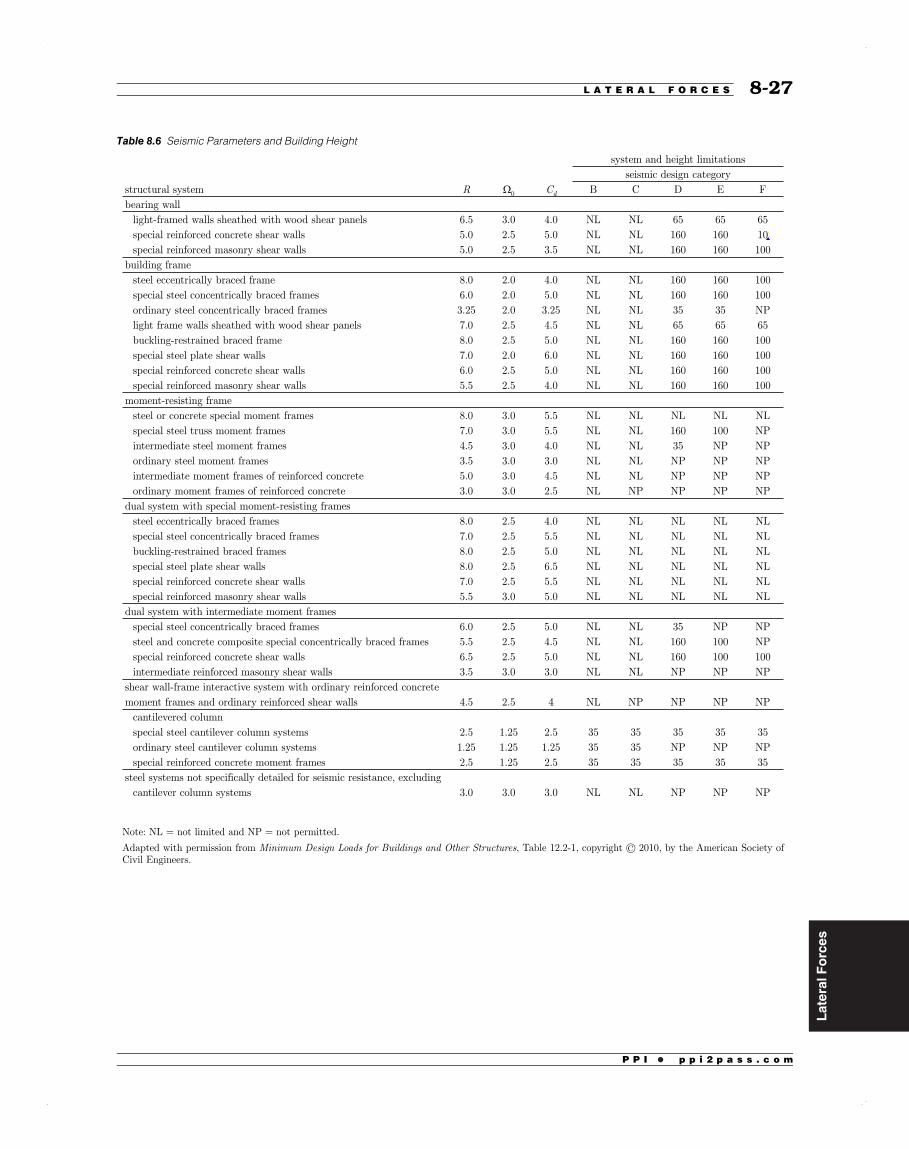
LateralForces
P P I • p p i 2 p a s s . c o m
8-27L A T E R A L F O R C E S 8-27
Table 8.6 Seismic Parameters and Building Height
Note: NL = not limited and NP = not permitted.
Adapted with permission from Minimum Design Loads for Buildings and Other Structures, Table 12.2-1, copyright © 2010, by the American Society of Civil Engineers.
system and height limitationsseismic design category
structural system R Ω0 Cd B C D E Fbearing wall
light-framed walls sheathed with wood shear panels 6.5 3.0 4.0 NL NL 65 65 65special reinforced concrete shear walls 5.0 2.5 5.0 NL NL 160 160 10special reinforced masonry shear walls 5.0 2.5 3.5 NL NL 160 160 100
building framesteel eccentrically braced frame 8.0 2.0 4.0 NL NL 160 160 100special steel concentrically braced frames 6.0 2.0 5.0 NL NL 160 160 100ordinary steel concentrically braced frames 3.25 2.0 3.25 NL NL 35 35 NPlight frame walls sheathed with wood shear panels 7.0 2.5 4.5 NL NL 65 65 65buckling-restrained braced frame 8.0 2.5 5.0 NL NL 160 160 100special steel plate shear walls 7.0 2.0 6.0 NL NL 160 160 100special reinforced concrete shear walls 6.0 2.5 5.0 NL NL 160 160 100special reinforced masonry shear walls 5.5 2.5 4.0 NL NL 160 160 100
moment-resisting framesteel or concrete special moment frames 8.0 3.0 5.5 NL NL NL NL NLspecial steel truss moment frames 7.0 3.0 5.5 NL NL 160 100 NPintermediate steel moment frames 4.5 3.0 4.0 NL NL 35 NP NPordinary steel moment frames 3.5 3.0 3.0 NL NL NP NP NPintermediate moment frames of reinforced concrete 5.0 3.0 4.5 NL NL NP NP NPordinary moment frames of reinforced concrete 3.0 3.0 2.5 NL NP NP NP NP
dual system with special moment-resisting framessteel eccentrically braced frames 8.0 2.5 4.0 NL NL NL NL NLspecial steel concentrically braced frames 7.0 2.5 5.5 NL NL NL NL NLbuckling-restrained braced frames 8.0 2.5 5.0 NL NL NL NL NLspecial steel plate shear walls 8.0 2.5 6.5 NL NL NL NL NLspecial reinforced concrete shear walls 7.0 2.5 5.5 NL NL NL NL NLspecial reinforced masonry shear walls 5.5 3.0 5.0 NL NL NL NL NL
dual system with intermediate moment framesspecial steel concentrically braced frames 6.0 2.5 5.0 NL NL 35 NP NPsteel and concrete composite special concentrically braced frames 5.5 2.5 4.5 NL NL 160 100 NPspecial reinforced concrete shear walls 6.5 2.5 5.0 NL NL 160 100 100intermediate reinforced masonry shear walls 3.5 3.0 3.0 NL NL NP NP NP
shear wall-frame interactive system with ordinary reinforced concretemoment frames and ordinary reinforced shear walls 4.5 2.5 4 NL NP NP NP NP
cantilevered columnspecial steel cantilever column systems 2.5 1.25 2.5 35 35 35 35 35ordinary steel cantilever column systems 1.25 1.25 1.25 35 35 NP NP NPspecial reinforced concrete moment frames 2.5 1.25 2.5 35 35 35 35 35
steel systems not specifically detailed for seismic resistance, excludingcantilever column systems 3.0 3.0 3.0 NL NL NP NP NP

LateralForces
P P I • p p i 2 p a s s . c o m
This latter expression controls for shorter periods up toapproximately 1 sec. For longer periods, the expressionprovides conservative values.
In accordance with ASCE/SEI7 Eq. 12.8-5, the value ofthe seismic response coefficient must not be taken less than
C S I0.044 0.01s DS e=
For those structures for which the 1 sec spectralresponse value is S1 ≥ 0.6g, the minimum value of theseismic response coefficient is given by ASCE/SEI7 Eq.12.8-6 as
CS IR
0.5s
e1=
Example 8.13
The two-story, reinforced concrete, special moment-resisting frame of Ex. 8.12 is used for a residential build-ing. Calculate the seismic response coefficient by usingthe alternative value for the fundamental period deter-mined in Ex. 8.12.
Solution
From previous examples, the relevant parameters are
S gS gITT
1.0
0.7
1.00
0.479†sec0.70†sec
DS
D
e
S
1
=====
The value of the response modification coefficient for aspecial moment-resisting frame is obtained fromTable 8.6 as
R 8.0=
The seismic response coefficient is given in ASCE/SEI7Sec. 12.8.1.1 as
CS IRT
(0.7)(1.00)
(8.0)(0.479†sec)
0.183
sD e1=
=
=
The maximum value of the seismic response coefficient is
CS I
R(1.0)(1.00)
8.00.125 [governs]
sDS e=
=
=
This follows since T<TS and the response of themoment-resisting frame lies in the flat topped segmentof the response curve.
Seismic Base ShearASCE/SEI7 Eq. 12.8-1 specifies the seismic base shear as
V C Ws=
Example 8.14
Calculate the seismic base shear for the two-story, rein-forced concrete, moment-resisting frame of Ex. 8.13.
Solution
The value of the effective seismic weight was derived inTable 8.6 as
W 1500†kips=
The value of the seismic response coefficient was derivedin Ex. 8.13 as
C 0.125s =
The base shear is given by ASCE/SEI7 Eq. 12.8-1 as
V C W(0.125)(1500†kips)
188†kips
s===
Building Configuration RequirementsThe static lateral force procedure is applicable to structuresthat satisfy prescribed conditions of regularity, occupancy,location, and height. A regular structure has mass, stiffness,and strength uniformly distributed over the height of thestructure and is without irregular features that will producestress concentrations. Vertical irregularities are defined inASCE/SEI7 Table 12.3-2 and horizontal irregularities inASCE/SEI7 Table 12.3-1. As defined in ASCE/SEI7Table 12.6-1, the equivalent lateral force method may beused in the design of a structure when a structure isassigned to seismic design category B or C. Additionally,the equivalent lateral force method may be used when astructure is assigned to seismic design category D, E, or Fand conforms to one of the following conditions.
• light-frame construction
• a risk category of I or II and does not exceed two sto-ries in height
• height not exceeding 160 ft and is a regular building
• height not exceeding 160 ft and has neither horizon-tal irregularities 1a (torsional) or 1b (extreme tor-sional), nor vertical irregularities 1a (soft story), 1b(extreme soft story), 2 (mass), or 3 (geometric)
8-31L A T E R A L F O R C E S 8-31

BridgeDesign
P P I • p p i 2 p a s s . c o m
The dynamic factor is not applied to
• the design lane load
• pedestrian loads
• centrifugal forces and braking forces
• retaining walls not subject to vertical loads from thesuperstructure
• foundation components that are entirely belowground level
• wood structures
The dynamic load allowance for culverts and otherburied structures is given by AASHTO Eq. 3.6.2.2-1 as
IM D33(1.0 0.125 )
0%E=
DE, the minimum depth of earth cover over the struc-ture, is in ft.
Example 9.3
For the four-span bridge of Ex. 9.2, determine the maxi-mum moment at support 2 produced by loading onedesign lane with the design lane load combined with thedesign truck. Include the effect of the dynamic loadallowance.
Solution
The dynamic load allowance for the support moment isgiven by AASHTO Table 3.6.2.1-1 as
IM 33%=
The dynamic factor is derived as
IIM
1100
133100
1.33
= +
= +
=
The static moment at support 2 caused by the twodesign trucks is given by Ex. 9.2 as
M 218†ft-kips2 =
The moment at support 2 caused by the two designtrucks, including the dynamic load allowance, is
M (1.33)(218†ft-kips)
290†ft-kips2 =
=
The combined moment produced by the design laneload and the two standard trucks, including thedynamic load allowance, is
M 106†ft-kips 290†ft-kips
396†ft-kips2 = +
=
The final design moment is given by AASHTOSec. 3.6.1.3.1 as
M (0.9)(396†ft-kips)
356†ft-kips2 =
=
Lateral Distribution of LoadsIn accordance with AASHTO Sec. 4.6.2.2.1 in the calcu-lation of bending moments for T-beam bridges, perma-nent loads of and on the deck may be distributeduniformly to all beams.
The distribution of live load depends on the torsionalstiffness of the bridge deck system and, if necessary,may be determined by several6,7,8,9 analytical methods.In accordance with AASHTO Sec. 4.6.2.2, however, thedistribution of live load may be calculated by empiricalexpressions, depending on the superstructure type andthe stringer spacing.
The types of superstructure for which the distributionfactor method may be used are illustrated in AASHTOTable 4.6.2.2.1-1. The method may be applied providedthat the following conditions are met.
• A single lane of live loading is analyzed.
• Multiple lanes of live loading producing approxi-mately the same force effect per lane are analyzed.
• The deck width is constant.
• The number of beams is not less than four (withsome exceptions).
• Beams are parallel and have approximately the samestiffness.
• The roadway part of the overhang does not exceed3 ft (with some exceptions).
• The curvature of the superstructure is less than thelimit specified in AASHTO Sec. 4.4.
Additional requirements are specified for each specificsuperstructure illustrated in AASHTO Table 4.6.2.2.1-1,and these are listed in AASHTO Table 4.6.2.2.2b-1.
A monolithic T-beam superstructure is listed as case (e)in AASHTO Table 4.6.2.2.1-1. For this type of bridge,the limitation on the beam spacing is
S3.5†ft 16.0†ft
9-5B R I D G E D E S I G N 9-5

BridgeDesign
P P I • p p i 2 p a s s . c o m
The previous expression is also applicable to a flangedsection with the neutral axis within the flange.
As specified in AASHTO Sec. 5.7.2.1 for grade 60 rein-forcement, fy may replace fs when, using fy in the calcula-tion, the resulting ratio c/ds does not exceed 0.6. If c/dsexceeds 0.6, strain compatibility should be used to deter-mine the stress in the mild steel tension reinforcement. Forgrade 100 reinforcement, the limiting ratio, c/ds, is 0.43.The limiting ratio, c/ds, for other grades of reinforcementmay be determined by linear interpolation.
The depth of the equivalent rectangular stress block isgiven by AASHTO Sec. 5.7.2.2 as
a c1=
The nominal flexural strength of a rectangular section,without nonprestressed compression reinforcement, isgiven by AASHTO Eq. 5.7.3.2.2-1 as
( ) ( )M A f da
A f da
2 2n ps ps p s s s= +
The factored flexural resistance is given by AASHTOEq. 5.7.3.2.1-1 as
M Mr n=
The resistance factor for a tension-controlled pre-stressed concrete section is given by AASHTOSec. 5.5.4.2.1 as
1.0=
Example 9.20
The area of the low-relaxation strand in the post-ten-sioned girder of Ex. 9.19 is 5.36 in2, and the strand has aspecified tensile strength of 270 kips/in2. The 28-daycompressive strength of the deck slab is 3 kips/in2.Determine the maximum factored moment at midspanand the design flexural capacity of the compositesection.
Solution
From Ex. 9.19, the total dead load moment on the com-posite section is
M M M M12,500†in-kips 12,000†in-kips
3000†in-kips27,500†in-kips
D g S DC= + +
= ++
=
The live load moment plus impact is
M 16,250†in-kipsL =
The strength I limit state moment is given by AASHTOEq. 3.4.1-1 as
M M M
(1.25)(27,500†in-kips)
(1.75)(16,250†in-kips)
62,813†in-kips
u p D LL IM L= +
=+
=
+
The effective prestress in the tendons after all losses isobtained from Ex. 9.19 as
fP
A
f
800†kips
5.36†in
149†kips/in
0.5
pee
ps
pu
2
2
=
=
=>
Therefore, AASHTO Sec. 5.7.3.1 is applicable.
The compression zone factor for 3 kips/in2 concrete is
0.851 =
The prestressing steel factor is given by AASHTOTable 5.7.3.1.1-1 as
k 0.28 [for†low-relaxation†strand]=
Assuming that the neutral axis lies within the flange, fora section without nonprestressed tension reinforcement,the distance from the extreme compression fiber to theneutral axis is given by AASHTO Eq. 5.7.3.1.1-4 as
cA f
f bkA f
d0.85
(5.36†in ) 270†kips
in
(0.85) 3†kips
in(0.85)(96†in)
(0.28)(5.36†in ) 270†kips
in78†in
6.79†in8†in
ps pu
cps pu
p1
22
2
22
=
+
=
+
=<
Therefore, the neutral axis does lie within the flange.
9-27B R I D G E D E S I G N 9-27
Brid
geDesig
n
P P I • p p i 2 p a s s . c o m
The depth of the equivalent rectangular stress block isgiven by AASHTO Sec. 5.7.2.2 as
= ==
a c (0.85)(6.79†in)
5.8†in1
The stress in bonded tendons at ultimate load is givenby AASHTO Eq. 5.7.3.1.1-1 as
=
=
=
f fkcd
1
270†kips
in1
(0.28)(6.79†in)
78†in
263.42†kips/in
ps pup
2
2
The nominal flexural strength of the section is given byAASHTO Eq. 5.7.3.2.2-1 as
=
=
=
( )M A f da2
(5.36†in ) 263.42†kips
in78†in
5.8†in2
106,036†in-kips
n ps ps p
22
The strain in the prestressing tendons at the nominalflexural strength is
=
=
=>
d c
c
(0.003)78†in 6.79†in
6.79†in0.0310.005
t cup
Therefore, from AASHTO Sec. 5.7.2.1, the section istension controlled and the resistance factor is given byAASHTO Sec. 5.5.4.2.1 as
= 1.0
The factored flexural resistance is
= ==>>
M M
MM
(1.0)(106,036†in-kips)
106,036†in-kips
1.33
[satisfactory]
[satisfies AASHTO Sec. 5.7.3.3.2]
r n
u
u
Cracking Moment
The cracking moment is the external moment that,when applied to the member after all losses haveoccurred, will cause cracking in the bottom fiber. This
cracking occurs when the stress in the bottom fiberexceeds the modulus of rupture, which is defined inAASHTO Sec. 5.4.2.6 for normal weight concrete as
=f f0.24r c
For a composite section, the cracking moment is definedin AASHTO Eq. 5.7.3.3.2-1 as
= +M S f f MSS
S f
( ) 1cr c cpe r dncc
nc
c r
3 2 1
The applicable factors for the cracking moment are asfollows.
=======
===
flexural cracking variability factor
1.2
1.6
prestress variability factor
1.1
1.0
ratio of specified minimum yield strength to
ultimate tensile strength of the reinforcement0.67
0.75
1.00
[precast segmental structures]
[other concrete structures]
[bonded tendons]
[unbonded tendons]
[A615, grade 60 reinforcement]
[A706, grade 60 reinforcement]
[prestressed†concrete†structures]
1
2
3
For noncomposite beams, Snc is substituted for Sc in theprevious expression. To prevent sudden tensile failure,AASHTO Sec. 5.7.3.3.2 requires that a beam have amoment capacity at least equal to the lesser of
==
M MM M1.33
n cr
n u
Example 9.21
Determine the cracking moment of the composite sec-tion of Ex. 9.19.
Solution
From Ex. 9.19, the bottom fiber stress due only to theeffective prestressing force after allowance for all pre-stress losses is
=f 2.579†kips/incpe2
In addition, the bending moment due to the noncompositedead load acting on the precast section is given by
= + = +
=
M M M 12,500†in-kips 12,000†in-kips
24,500†in-kipsdnc g S
9-289-28 S E S T R U C T U R A L E N G I N E E R I N G R E F E R E N C E M A N U A L
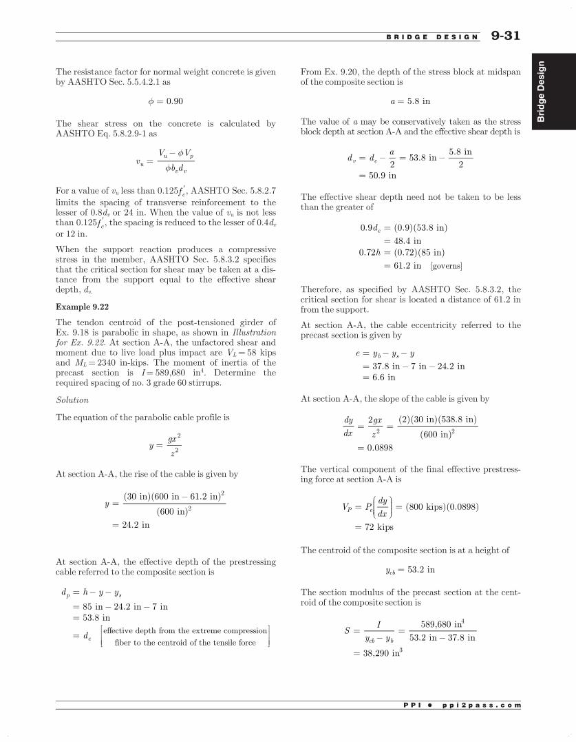
BridgeDesign
P P I • p p i 2 p a s s . c o m
The resistance factor for normal weight concrete is givenby AASHTO Sec. 5.5.4.2.1 as
= 0.90
The shear stress on the concrete is calculated byAASHTO Eq. 5.8.2.9-1 as
=vV V
b duu p
v v
For a value of vu less than 0.125fc, AASHTO Sec. 5.8.2.7limits the spacing of transverse reinforcement to thelesser of 0.8dv or 24 in. When the value of vu is not lessthan 0.125fc, the spacing is reduced to the lesser of 0.4dvor 12 in.
When the support reaction produces a compressivestress in the member, AASHTO Sec. 5.8.3.2 specifiesthat the critical section for shear may be taken at a dis-tance from the support equal to the effective sheardepth, dv.
Example 9.22
The tendon centroid of the post-tensioned girder ofEx. 9.18 is parabolic in shape, as shown in Illustrationfor Ex. 9.22. At section A-A, the unfactored shear andmoment due to live load plus impact are VL= 58 kipsand ML= 2340 in-kips. The moment of inertia of theprecast section is I= 589,680 in4. Determine therequired spacing of no. 3 grade 60 stirrups.
Solution
The equation of the parabolic cable profile is
=ygxz
2
2
At section A-A, the rise of the cable is given by
=
=
y(30†in)(600†in 61.2†in)
(600†in)
24.2†in
2
2
At section A-A, the effective depth of the prestressingcable referred to the composite section is
=
==
=
d h y y
d
85†in 24.2†in 7†in53.8†in
effective†depth†from†the†extreme†compression
fiber†to†the†centroid†of†the†tensile†force
p s
e
From Ex. 9.20, the depth of the stress block at midspanof the composite section is
=a 5.8†in
The value of a may be conservatively taken as the stressblock depth at section A-A and the effective shear depth is
= =
=
d da2
53.8†in5.8†in
250.9†in
v e
The effective shear depth need not be taken to be lessthan the greater of
====
d
h
0.9 (0.9)(53.8†in)
48.4†in0.72 (0.72)(85†in)
61.2†in [governs]
e
Therefore, as specified by AASHTO Sec. 5.8.3.2, thecritical section for shear is located a distance of 61.2 infrom the support.
At section A-A, the cable eccentricity referred to theprecast section is given by
===
e y y y37.8†in 7†in 24.2†in6.6†in
b s
At section A-A, the slope of the cable is given by
= =
=
dydx
gxz
2 (2)(30†in)(538.8†in)
(600†in)
0.0898
2 2
The vertical component of the final effective prestress-ing force at section A-A is
= =
=
V Pdydx
(800†kips)(0.0898)
72†kips
P e
The centroid of the composite section is at a height of
=y 53.2†incb
The section modulus of the precast section at the cent-roid of the composite section is
= =
=
SI
y y589,680†in
53.2†in 37.8†in
38,290†in
cb b
4
3
9-31B R I D G E D E S I G N 9-31
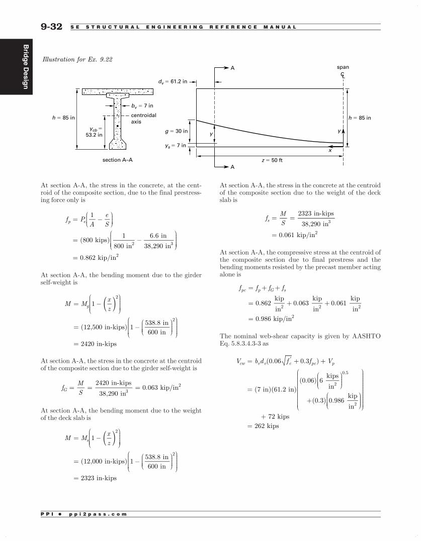
Brid
geDesig
n
P P I • p p i 2 p a s s . c o m
At section A-A, the stress in the concrete, at the cent-roid of the composite section, due to the final prestress-ing force only is
=
=
=
f PA
eS
1
(800†kips)1
800†in
6.6†in
38,290†in
0.862†kip/in
p e
2 3
2
At section A-A, the bending moment due to the girderself-weight is
=
=
=
( )M Mxz
1
(12,500†in-kips) 1538.8†in600†in
2420†in-kips
g
2
2
At section A-A, the stress in the concrete at the centroidof the composite section due to the girder self-weight is
= = =fMS
2420†in-kips
38,290†in0.063†kip/inG 3
2
At section A-A, the bending moment due to the weightof the deck slab is
=
=
=
( )M Mxz
1
(12,000†in-kips) 1538.8†in600†in
2323†in-kips
s
2
2
At section A-A, the stress in the concrete at the centroidof the composite section due to the weight of the deckslab is
= =
=
fMS
2323†in-kips
38,290†in
0.061†kip/in
s 3
2
At section A-A, the compressive stress at the centroid ofthe composite section due to final prestress and thebending moments resisted by the precast member actingalone is
= + +
= + +
=
f f f f
0.862†kip
in0.063†
kip
in0.061†
kip
†in
0.986†kip/in
pc p G s
2 2 2
2
The nominal web-shear capacity is given by AASHTOEq. 5.8.3.4.3-3 as
= + +
=
+
+=
V b d f f V(0.06 0.3 )
(7†in)(61.2†in)(0.06) 6†
kips
in
(0.3) 0.986†kip
in
72†kips262†kips
cw v v c pc p
2
0.5
2
9-329-32 S E S T R U C T U R A L E N G I N E E R I N G R E F E R E N C E M A N U A L
h = 85 in
bv = 7 in
h = 85 in
z = 50 ft
ycb = 53.2 in
ys = 7 in
g = 30 in
dv = 61.2 in
centroidalaxis
CL
y y
x
A
A span
section A–A
Illustration for Ex. 9.22
BridgeDesign
P P I • p p i 2 p a s s . c o m
The compressive stress in the bottom fiber of the pre-cast member at section A-A due to the final prestressingforce is
= +
= +
=
f PA
eS
1
(800†kips)1
800†in
6.6†in
15,600†in
1.338†kips/in
cpe enc
2 3
2
At section A-A, the stress in the concrete at the bottomfiber due to the dead load imposed on the precast sec-tion is, from Ex. 9.19,
=
=
=
+ ( )f fxz
1
1.570†kips
in1
538.8†in600†in
0.304†kip/in [tension]
d Gb Sb
2
2
2
2
The moment causing flexural cracking at the sectiondue to externally applied loads is given by AASHTOEq. 5.8.3.4.3-2 as
= +
=+
=
>
M S f f f( )
(21,200†in )0.20 6†
kips
in1.338†
kips
in
0.304†kip
in32,307†in-kips
2340†in-kips the†given†unfactored†applied
moment†at†section†A-A
cre c r cpe d
32 2
2
Hence, flexural-shear cracking does not occur at sectionA-A; the web-shear capacity controls with the nominalshear strength given by
==
V V262†kips
c cw
The design shear capacity is
==
V (0.9)(262†kips)
236†kipsc
From Ex. 9.18, the cross-sectional area of the girder is=A 800†inG
2. At section A-A, the shear force due to thegirder self-weight is
= =
=
=
( )
V w x A x
0.150†kip
ft
800†in
12†inft
(538.8†in)
12†inft
37.4†kips
G G c G
3
2
2
The cross-sectional area of the slab is =AF
=(8†in)(96†in) 768†in2. At section A-A, the shear forcedue to the self-weight of the slab is
= =
=
=
( )
V w x A x
0.150†kip
ft
768†in
12†inft
(538.8†in)
12†inft
36.0†kips
S S c F
3
2
2
At section A-A, the shear force due to the dead loadimposed on the composite section is
= =
=
V w x0.20†
kip
ft(538.8†in)
12†inft
9.0†kips
DC DC
At section A-A, the total dead load shear force on thecomposite section is
= + += + +=
V V V V37.4†kips 36.0†kips 9.0†kips82.4†kips
D G S DC
The live load shear plus impact is given as
=V 58†kipsL
9-33B R I D G E D E S I G N 9-33

Brid
geDesig
n
P P I • p p i 2 p a s s . c o m
The strength I limit state shear force is given byAASHTO Eq. 3.4.1-1 as
V V V
V
(1.25)(82.4†kips) (1.75)(58†kips)
205†kips
u p D LL IM L
c
= +
= +=<
+
Hence, a minimum area of shear reinforcement isrequired and is given by AASHTO Eq. 5.8.2.5-1 as
As
f bf
0.0316
(0.0316)
6†kips
in(7†in)
60†kips
in
0.0090†in /in
v c v
y
2
2
2
=
=
=
The shear stress on the concrete is calculated byAASHTO Eq. 5.8.2.9-1 as
vV V
b d
f
203†kips (0.9)(72†kips)
(0.9)(7†in)(61.2†in)
0.358†kip/in
0.125 (0.75†kip/in )
uu p
v v
c
2
2
=
=
=
<
Therefore, AASHTO Sec. 5.8.2.7 limits the spacing oftransverse reinforcement to the lesser of
s d
s
0.8
(0.8)(61.2†in)
49†in24†in [governs]
v====
Providing no. 3 stirrups at the maximum permittedspacing of 24 in gives a value of
As
0.22†in24†in
0.0092†in /in
0.0090†in /in
[satisfactory]
v2
2
2
=
=
>
Prestress Losses
Nomenclature
Ag gross area of section in2
Aps area of prestressing steel in2
Eci modulus of elasticity of concrete at timeof initial prestress
kips/in2
Ep modulus of elasticity of prestressing steel kips/in2
fcgp compressive stress at centroid of pre-stressing steel due to prestress and self-weight of girder at transfer
kips/in2
fpj stress in the prestressing steel at jacking kips/in2
g drape of prestressing steel in
Ig moment of inertia of precast girder in4
K wobble friction coefficient per foot ofprestressing tendon
–
lpx distance from free end of cable to sectionunder consideration
ft
Mg bending moment due to self-weight ofprecast member
in-kips
ni modular ratio at transfer –N number of identical prestressing tendons –PES loss of prestress force due to elastic
shorteningkips
Pi force in prestressing steel immediatelyafter transfer
kips
Po force in prestressing steel at anchorage kips
R radius of curvature of tendon profile ft
Symbols
α angular change of tendon profile fromjacking end to any point x
radians
ΔfpES loss of prestress due to elastic shortening kips/in2
ΔfpF prestress loss due to friction kips/in2
ΔfpLT long-term prestress loss due to creep andshrinkage of concrete and relaxation ofsteel
kips/in2
μ curvature friction coefficient –
Friction Losses
AASHTO Sec. 5.9.5.2.2 determines friction losses fromthe equation
( )f f e1pF pjKx( )= µ+
Values of the wobble and curvature friction coefficientsare given in AASHTO Table 5.9.5.2.2b-1 and for pre-stressing strand are
K 0.00020.15†to†0.25µ
==
9-349-34 S E S T R U C T U R A L E N G I N E E R I N G R E F E R E N C E M A N U A L


![· 178 w2~uz− 179 w2~− 182 w2¶a 183 w2,v0 185 w2fl 186 w2,´‡ 187 w2,^M 188 w2,â 190 w2,˛− 195 w2,ðg− 196 w2,ðg! 198 w2,ð¾ 200 w2,ð−a 201 w2,ðgG Ž ]* Z˜ ß9ü](https://img.pdfslide.us/doc/110x75/5ec4169f9cf111271f3cdc4b/178-w2uza-179-w2a-182-w2a-183-w2v0-185-w2i-186-w2a-187-w2m-188.jpg)