Embed Size (px)
Citation preview
Course: Agricultural technology
Subject: Tractor and its power units year/semester: III/V
Q.code: 306
Part-A Answer any 5 questions. Question 8 is compulsory. 5 x 2 = 10 marks
1. What are the different types of piston rings? Compression ring and oil ring.
2. Where do the cam shaft get its drive from? How? Cam shaft gets its drive from crankshaft through timing gears or chains.
3. What is the function of a fuel injection pump? The function of the fuel injection pump is to meter the correct quantity of fuel to the correct cylinder at the correct time with respect to the load and speed.
4. What are the different types of air cleaners? i. Oil wetted mesh type ii. Dry type and iii. Wet or oil bath type.
5. What is the function of a thermostat valve? It is a kind of a check valve which opens and closes with the effect of temperature. Only when the working temperature is reached, the thermostat valve is opened and will allow the water to pass through the radiator.
6. What is the function of a battery? Battery is a device that converts chemical energy into electrical energy. In automobile it is used to store electrical energy and used to supply current for starting motor, lighting and other purposes when generator is not running.
7. What is the purpose of a differential lock? The purpose of this is to join both the half axles so that even if one wheel is under less resistance, the tractor comes out of the mud as both wheels move with the same speed and apply equal traction.
8. What are the different controls of a tractor hydraulic system? i. Implement control
ii. Position control iii. Draft control
Part-B Answer any 5 questions. Question 16 is compulsory. 5 x 3 = 15 marks
9. List the main components of an IC engine. Engine block, cylinder head, gasket, piston, piston ring, piston pin, connecting rod, crank shaft, cam shaft, bearings, valves and valve assemblies, fly wheel.
10. State and explain Boyle’s law. If the temperature of a gas is kept constant, the volume of a specific mass (m) of a gas is
inversely proportional to the pressure.
i.e., V α 1/P - (1)
P V = C where c is the proportionality constant.
If V1 is the volume of a gas at pressure P1 and V2 represents the volume of the same gas at
pressure P2, then we have P1 V1 = P2 V2 = C.
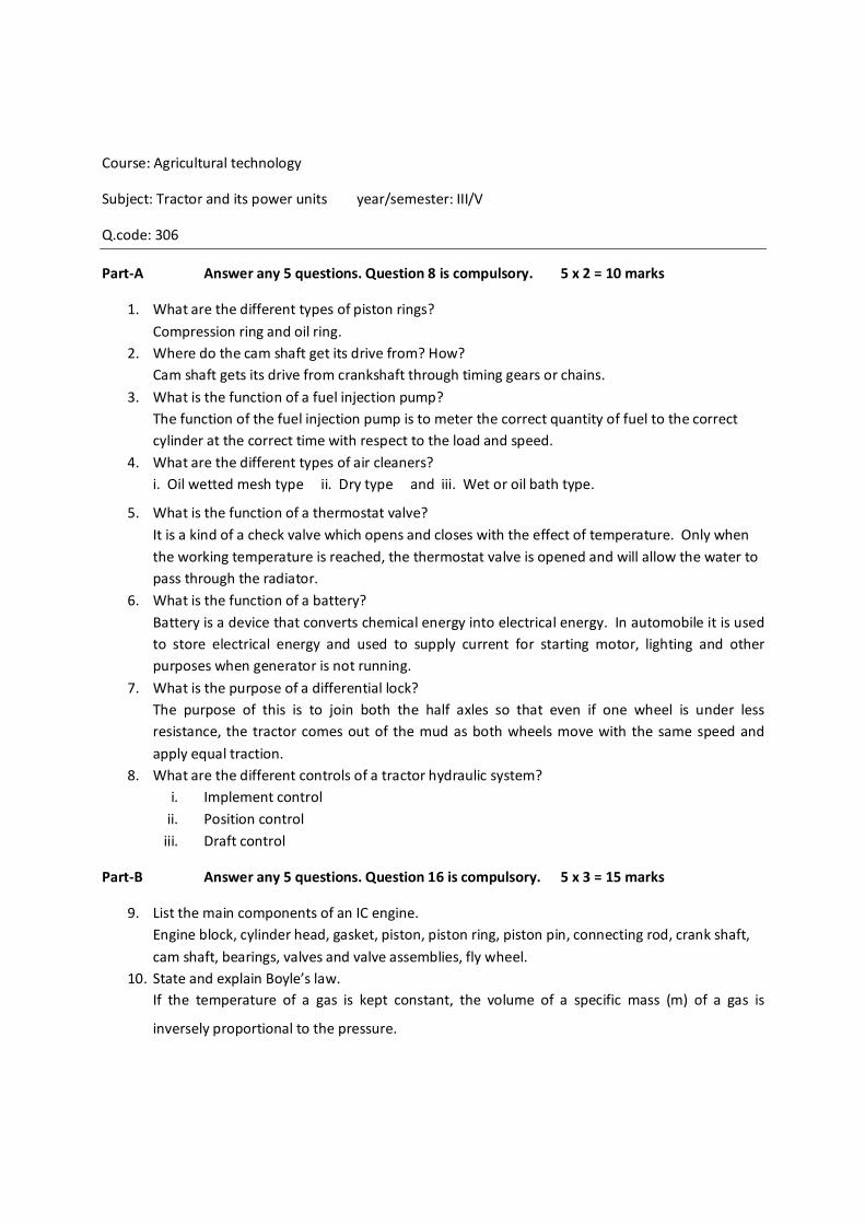
11. What are the different types of nozzles? Explain any one.
1. Single hole 2. Multi hole 3. Pintle and 4. Pintaux.
Single hole nozzle consists of a single hole at the center of the nozzle which is closed by the nozzle
valve. The size of the hole is about .2mm. If the hole is made at an angle then it is called conical end
type.
Multi-hole nozzle consists of two or more holes bored in the side of the valve seating. The number
of holes may be up to seven. The number and the size depend on the requirement of the engine.
The hole angle may be from 20º.
In Pintle nozzle the stem of the nozzle valve is extended to form a pin or pintle which protrudes
through the mouth of the nozzle. The size and shape of the pintle can be varied according to the
requirement. The spray cone in this is generally 60º.
Pintax nozzle is an improvement of pintle nozzle. This type of nozzles are suitable for starting
the engine from cold condition. Due to the typical shape of the valve, at starting speed it gets lifted
sufficiently for permitting the fuel to be injected through the auxiliary hole. With the start of the
engine, the fuel lifts the needle fully and discharges the fuel through the main orifice.
12. What are the major components of a diesel fuel system? a. 1. Fuel tank 2. Fuel filter 3. Feed pump
b. 4. Fuel injection pump 5. Nozzle 6. Fuel gauge
c. 7. Lines for connection 13. What is the need of a cooling system? a) The temperature inside the cylinder reaches up to 1500 to 2000ºC which is above the melting
point of the material of the cylinder body. Therefore if the heat is not dissipated, the engine will collapse.
b) Due to the high temperature, the film of the lubricating oil will get oxidized resulting in piston seizure.
c) Over heating will lead to distortion of engine parts. d) High temperature will lower the volumetric efficiency.
14. What are the main objectives of a lubrication system? Objectives:
To reduce friction between moving parts.
To reduce wear of the moving parts.
To act as a cooling medium for removing heat.
To keep the engine parts clean.
To absorb shock between bearings and other engine parts, thus reducing noise.
To form good seal between piston rings and cylinder walls.
To prevent deposition of carbon inside cylinder.
To prevent oxidation which cause sludge.
15. What are the functions of a differential?
a) On straight travel, it allows both rear wheels of tractor to get equal power and speed. b) On turn, the differential allows the inner side wheel to move slower than that of the outer
wheel. 16. Give the classification of brakes.
Classification of brakes: 1. Based on braking contact:
a. Internal expanding shoe. b. External contracting type.
2. Based on construction: a. Drum brake. b. Disc brake.
3. Based on purpose: a. service brake b. parking brake.
4. Based on location: a. Transmission brake b. wheel brake. 5. Based on actuation: a. Mechanical brake b. hydraulic brake
b. air brake. d. air assisted hydraulic brake e. electric brake f. vacuum brake.
Part – C Answer all the questions. 5 x 10 = 50 marks
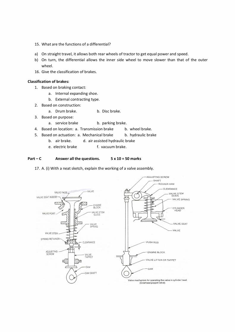
17. A. (i) With a neat sketch, explain the working of a valve assembly.
The valve stem moves up and down, inside the passage called guide, which is fitted in the engine
block. The heads of the valves, called valve face is generally ground to have a 45º angle so as to
fit properly on the valve seat in the block and prevent leakage. The valve springs provides
return of the valve after operation. When the cam rotates the tappet is lifted, thereby lifting the
valve open. In the closed position of the valve, a slight clearance is necessary between the valve
tappet and the stem. This clearance is allowed for expansion of the parts due to heat created in
the engine. This can be adjusted with the help of the tappet screws. Timing of the valve
opening and closing can also be varied by adjusting this.
As the exhaust valve is exposed to the hot gas, more clearance is given to it. Valve seats and
inserts are pressed into the block to reduce the wear and prevent leakage in the valves.
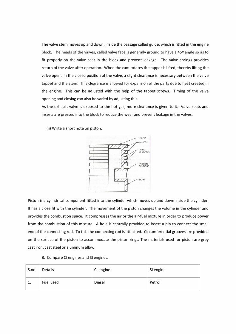
(ii) Write a short note on piston.
Piston is a cylindrical component fitted into the cylinder which moves up and down inside the cylinder.
It has a close fit with the cylinder. The movement of the piston changes the volume in the cylinder and
provides the combustion space. It compresses the air or the air-fuel mixture in order to produce power
from the combustion of this mixture. A hole is centrally provided to insert a pin to connect the small
end of the connecting rod. To this the connecting rod is attached. Circumferential grooves are provided
on the surface of the piston to accommodate the piston rings. The materials used for piston are grey
cast iron, cast steel or aluminum alloy.
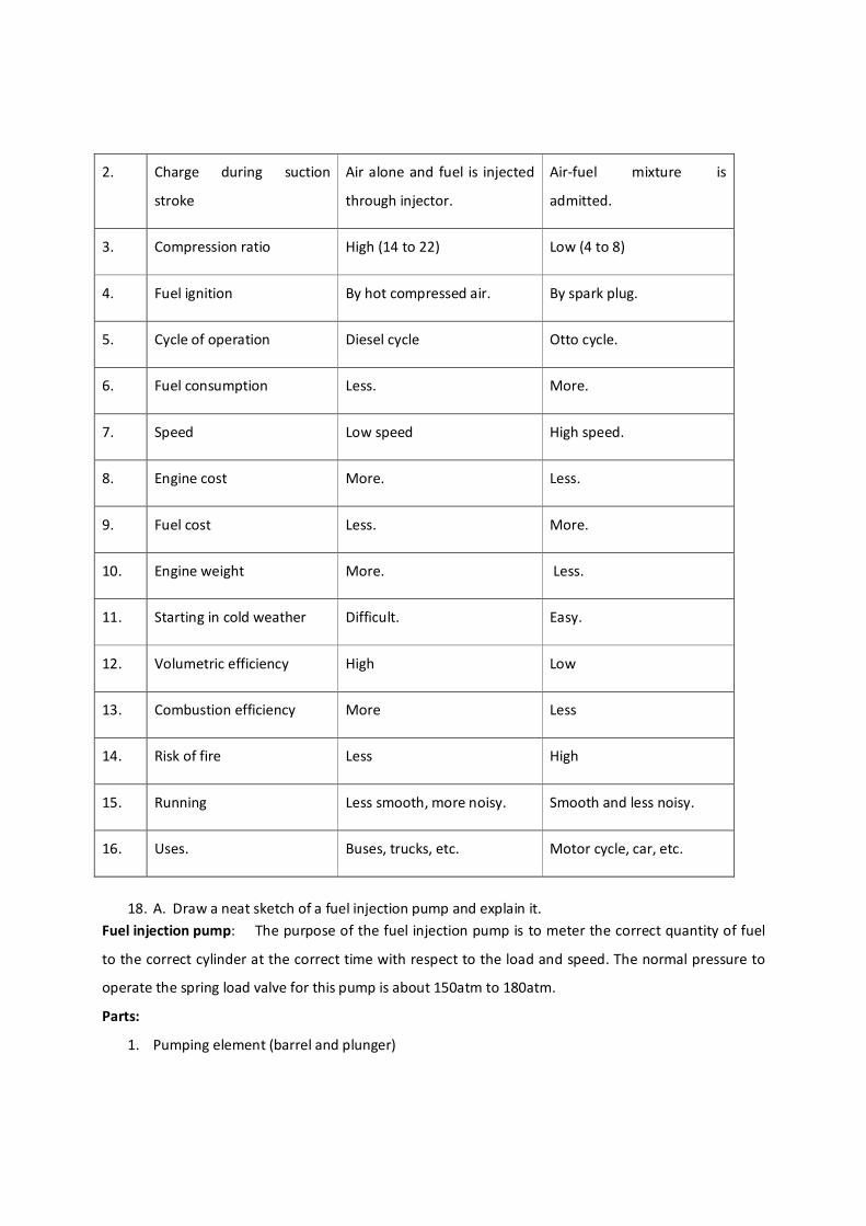
B. Compare CI engines and SI engines.
S.no Details CI engine SI engine
1. Fuel used Diesel Petrol
2. Charge during suction
stroke
Air alone and fuel is injected
through injector.
Air-fuel mixture is
admitted.
3. Compression ratio High (14 to 22) Low (4 to 8)
4. Fuel ignition By hot compressed air. By spark plug.
5. Cycle of operation Diesel cycle Otto cycle.
6. Fuel consumption Less. More.
7. Speed Low speed High speed.
8. Engine cost More. Less.
9. Fuel cost Less. More.
10. Engine weight More. Less.
11. Starting in cold weather Difficult. Easy.
12. Volumetric efficiency High Low
13. Combustion efficiency More Less
14. Risk of fire Less High
15. Running Less smooth, more noisy. Smooth and less noisy.
16. Uses. Buses, trucks, etc. Motor cycle, car, etc.
18. A. Draw a neat sketch of a fuel injection pump and explain it.
Fuel injection pump: The purpose of the fuel injection pump is to meter the correct quantity of fuel
to the correct cylinder at the correct time with respect to the load and speed. The normal pressure to
operate the spring load valve for this pump is about 150atm to 180atm.
Parts:
1. Pumping element (barrel and plunger)
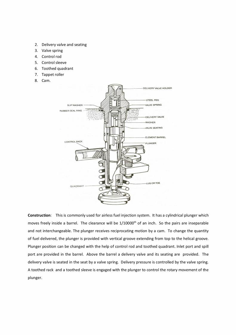
2. Delivery valve and seating 3. Valve spring 4. Control rod 5. Control sleeve 6. Toothed quadrant 7. Tappet roller 8. Cam.
Construction: This is commonly used for airless fuel injection system. It has a cylindrical plunger which
moves freely inside a barrel. The clearance will be 1/10000th of an inch. So the pairs are inseparable
and not interchangeable. The plunger receives reciprocating motion by a cam. To change the quantity
of fuel delivered, the plunger is provided with vertical groove extending from top to the helical groove.
Plunger position can be changed with the help of control rod and toothed quadrant. Inlet port and spill
port are provided in the barrel. Above the barrel a delivery valve and its seating are provided. The
delivery valve is seated in the seat by a valve spring. Delivery pressure is controlled by the valve spring.
A toothed rack and a toothed sleeve is engaged with the plunger to control the rotary movement of the
plunger.
Working:
When the plunger is at BDC, fuel enters through inlet port from feed pump. In a primed system, barrel
and pipes to the injector are full of fuel. When the cam rotates, the plunger rises closing both the barrel
ports and cuts the fuel supply. The fuel is trapped and the only way out is through the delivery valve
which is mounted above the barrel. Rising plunger increases the pressure of fuel causing the valve to
open against the spring tension. Now the fuel enters into the injector. As the injector is full of fuel, this
fuel pressure lifts the nozzle needle thereby spraying the fuel inside the cylinder.
Fuel supply to the injector is continued till the helical groove reaches the spillway port. At this stage,
the spill port connects the space above the plunger through the vertical slot and allows the fuel to
return through the spill port. This releases the pressure on the spring and the valve return back to its
seat. Thus the fuel supply to the injector is stopped.
The position of the helical groove controls the quantity of fuel being supplied. When the vertical slot is
in-line with the spill port, there will be no supply of fuel to the injector, called zero delivery. By rotating
the plunger the position of the helical groove and the vertical slot is changed which in turn controls the
quantity of fuel supplied to the nozzle.
With the control rack pulled out, the vertical groove will be in line with the spill port and all the fuel will
flow into the spill port and no fuel will go the injector. This position is called no injection position. In the
idling position, vertical groove is near the spill port and the helical groove opens the spill port with little
rise in the plunger there by allowing small amount of fuel. When the vertical groove is near the inlet
port, the helical groove will have its maximum stroke length and so full injection takes place. When the
vertical groove is in the middle, partial flow will take place.
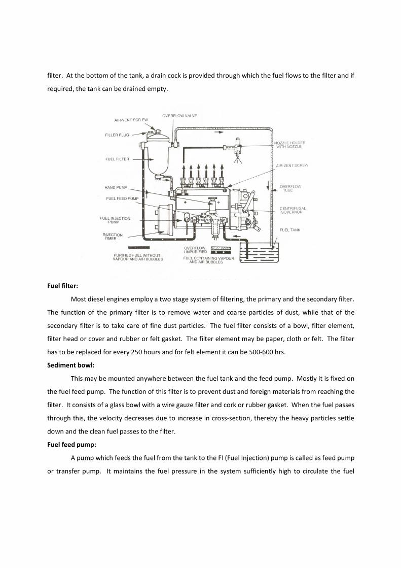
B. Draw a simple sketch of a diesel fuel system and explain its components. Fuel is pumped from the fuel tank by a transfer or feed pump through strainers and filters (primary
and secondary filter). From there it is taken to the fuel injection pump. Injection pump delivers the
fuel at high pressure to the nozzle. Through the nozzle, fuel is injected into the individual cylinder.
The excess fuel returns to the tank.
Fuel tank:
This is the reservoir of fuel which is made of MS sheet of sufficient capacity to store the fuel for
about 10 hours of working. Inside the tank there are two or three baffle plates provided to give more
rigidity and to prevent the diesel from surging from side to side. The tank cap is provided with a pin hole
to maintain atmospheric pressure inside the tank. If the hole gets chocked, the fuel will not flow to the
filter. At the bottom of the tank, a drain cock is provided through which the fuel flows to the filter and if
required, the tank can be drained empty.
Fuel filter:
Most diesel engines employ a two stage system of filtering, the primary and the secondary filter.
The function of the primary filter is to remove water and coarse particles of dust, while that of the
secondary filter is to take care of fine dust particles. The fuel filter consists of a bowl, filter element,
filter head or cover and rubber or felt gasket. The filter element may be paper, cloth or felt. The filter
has to be replaced for every 250 hours and for felt element it can be 500-600 hrs.
Sediment bowl:
This may be mounted anywhere between the fuel tank and the feed pump. Mostly it is fixed on
the fuel feed pump. The function of this filter is to prevent dust and foreign materials from reaching the
filter. It consists of a glass bowl with a wire gauze filter and cork or rubber gasket. When the fuel passes
through this, the velocity decreases due to increase in cross-section, thereby the heavy particles settle
down and the clean fuel passes to the filter.
Fuel feed pump:
A pump which feeds the fuel from the tank to the FI (Fuel Injection) pump is called as feed pump
or transfer pump. It maintains the fuel pressure in the system sufficiently high to circulate the fuel
through the filters. There are mainly two types, a. Mechanical feed pump (plunger type and
diaphragm type) and b. Electrical pump.
Hand priming pump:
The function of this pump is to feed the fuel from the tank to the filter or FI pump before
starting the engine or to bleed the air of the system. It is fitted on the supply side of the feed pump. It
consists of a pump body, single acting plunger pump rod and knurled knob. In order to operate this, the
knurled knob is screwed out until the plunger can be pulled upward. This opens the valve and allows
the fuel to flow into the suction chamber. When the plunger is pressed down, the inlet valve closes and
the outlet valve opens. The fuel then passes from the feed pump to FI pump. After use it is essential to
screw the knob tightly again. The quantity delivered per stroke is about 6ml.
Fuel injection pump: The purpose of the fuel injection pump is to meter the correct quantity of fuel
to the correct cylinder at the correct time with respect to the load and speed. The normal pressure to
operate the spring load valve for this pump is about 150atm to 180atm.
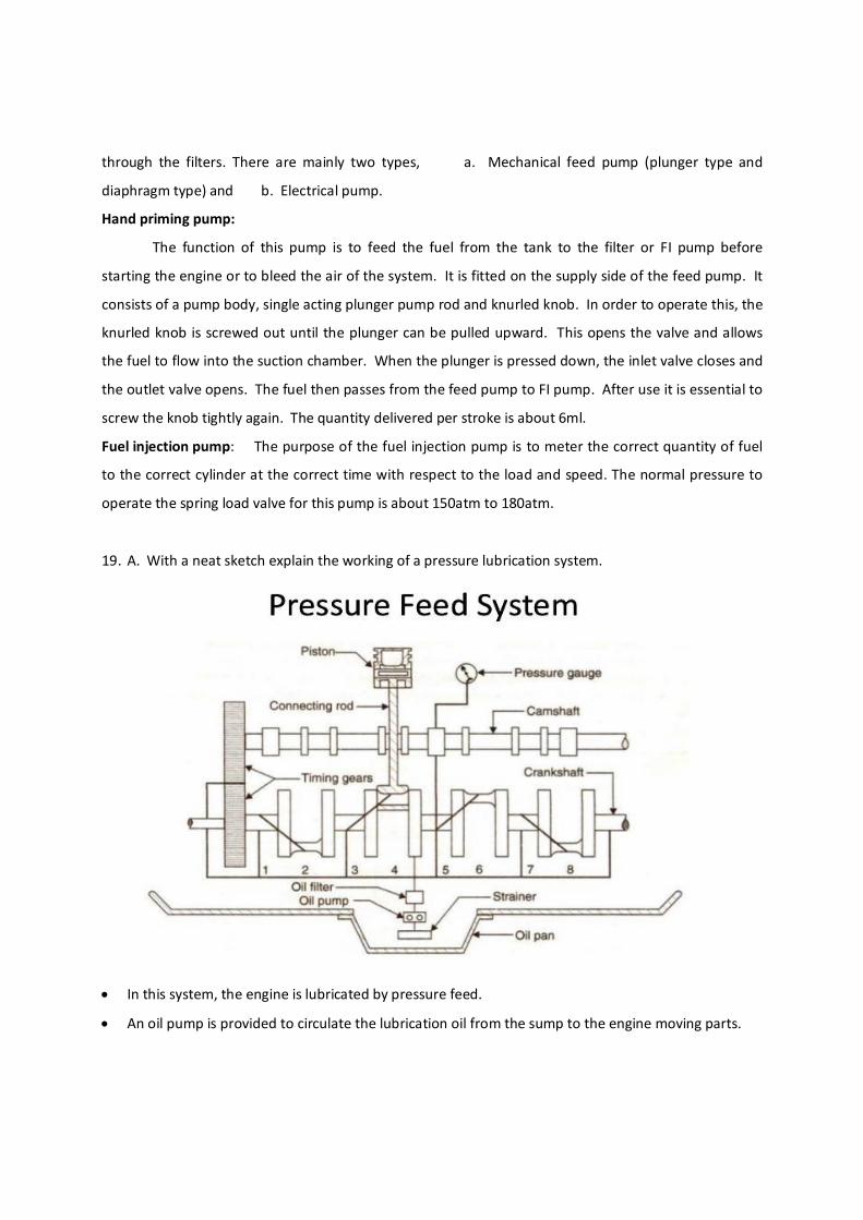
19. A. With a neat sketch explain the working of a pressure lubrication system.
In this system, the engine is lubricated by pressure feed.
An oil pump is provided to circulate the lubrication oil from the sump to the engine moving parts.
The oil pump takes the oil from the sump through the strainer and delivers to the main gallery
through filters at a pressure of 2 to 4 kg/cm2.
It passes through drilled holes to the main bearings, camshaft bearings and partially to the
connecting rod bearings.
Some engines may have passages in the rods to supply the oil to the piston pins from big end.
The liner is lubricated by the oil thrown off from the connecting rod and piston pin bearings.
Separate lines will be provided to lubricate cam shaft and timing gears.
Valve mechanisms will be lubricated by oil gallery leading through them.
Oil pressure gauge will be fitted to the system to monitor the flow of the lubricating oil.
Oil strainer and filters clean the oil.
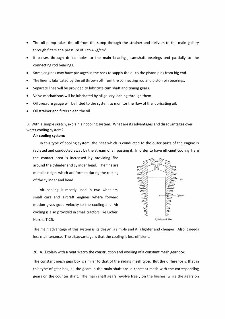
B. With a simple sketch, explain air cooling system. What are its advantages and disadvantages over water cooling system?
Air cooling system:
In this type of cooling system, the heat which is conducted to the outer parts of the engine is
radiated and conducted away by the stream of air passing it. In order to have efficient cooling, here
the contact area is increased by providing fins
around the cylinder and cylinder head. The fins are
metallic ridges which are formed during the casting
of the cylinder and head.
Air cooling is mostly used in two wheelers,
small cars and aircraft engines where forward
motion gives good velocity to the cooling air. Air
cooling is also provided in small tractors like Eicher,
Harsha T-25.
The main advantage of this system is its design is simple and it is lighter and cheaper. Also it needs
less maintenance. The disadvantage is that the cooling is less efficient.
20. A. Explain with a neat sketch the construction and working of a constant mesh gear box.
The constant mesh gear box is similar to that of the sliding mesh type. But the difference is that in
this type of gear box, all the gears in the main shaft are in constant mesh with the corresponding
gears on the counter shaft. The main shaft gears revolve freely on the bushes, while the gears on
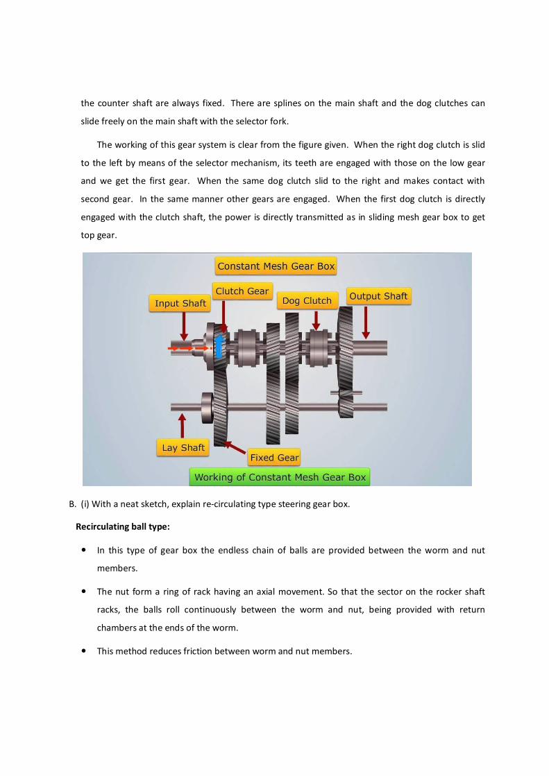
the counter shaft are always fixed. There are splines on the main shaft and the dog clutches can
slide freely on the main shaft with the selector fork.
The working of this gear system is clear from the figure given. When the right dog clutch is slid
to the left by means of the selector mechanism, its teeth are engaged with those on the low gear
and we get the first gear. When the same dog clutch slid to the right and makes contact with
second gear. In the same manner other gears are engaged. When the first dog clutch is directly
engaged with the clutch shaft, the power is directly transmitted as in sliding mesh gear box to get
top gear.
B. (i) With a neat sketch, explain re-circulating type steering gear box.
Recirculating ball type:
In this type of gear box the endless chain of balls are provided between the worm and nut
members.
The nut form a ring of rack having an axial movement. So that the sector on the rocker shaft
racks, the balls roll continuously between the worm and nut, being provided with return
chambers at the ends of the worm.
This method reduces friction between worm and nut members.
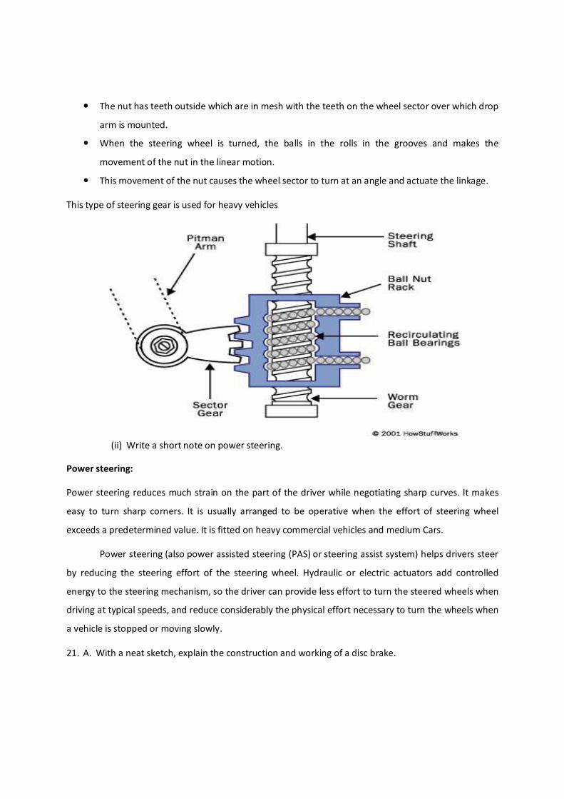
The nut has teeth outside which are in mesh with the teeth on the wheel sector over which drop
arm is mounted.
When the steering wheel is turned, the balls in the rolls in the grooves and makes the
movement of the nut in the linear motion.
This movement of the nut causes the wheel sector to turn at an angle and actuate the linkage.
This type of steering gear is used for heavy vehicles
(ii) Write a short note on power steering.
Power steering:
Power steering reduces much strain on the part of the driver while negotiating sharp curves. It makes
easy to turn sharp corners. It is usually arranged to be operative when the effort of steering wheel
exceeds a predetermined value. It is fitted on heavy commercial vehicles and medium Cars.
Power steering (also power assisted steering (PAS) or steering assist system) helps drivers steer
by reducing the steering effort of the steering wheel. Hydraulic or electric actuators add controlled
energy to the steering mechanism, so the driver can provide less effort to turn the steered wheels when
driving at typical speeds, and reduce considerably the physical effort necessary to turn the wheels when
a vehicle is stopped or moving slowly.
21. A. With a neat sketch, explain the construction and working of a disc brake.
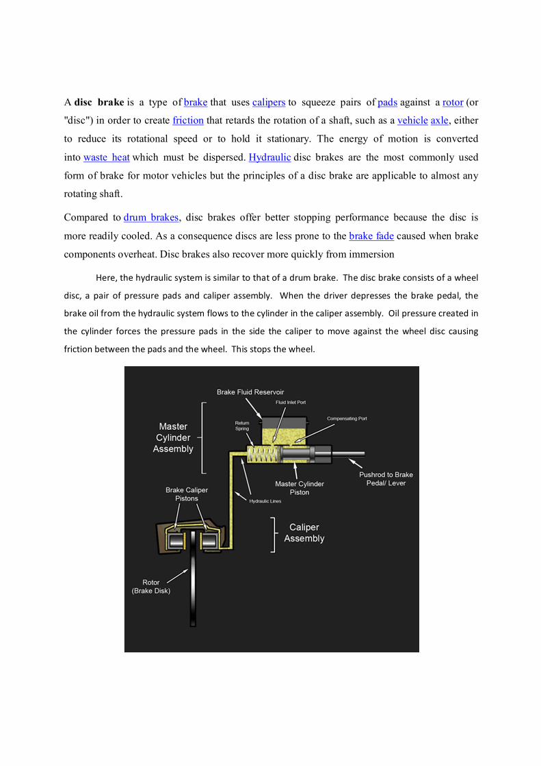
A disc brake is a type of brake that uses calipers to squeeze pairs of pads against a rotor (or
"disc") in order to create friction that retards the rotation of a shaft, such as a vehicle axle, either
to reduce its rotational speed or to hold it stationary. The energy of motion is converted
into waste heat which must be dispersed. Hydraulic disc brakes are the most commonly used
form of brake for motor vehicles but the principles of a disc brake are applicable to almost any
rotating shaft.
Compared to drum brakes, disc brakes offer better stopping performance because the disc is
more readily cooled. As a consequence discs are less prone to the brake fade caused when brake
components overheat. Disc brakes also recover more quickly from immersion
Here, the hydraulic system is similar to that of a drum brake. The disc brake consists of a wheel
disc, a pair of pressure pads and caliper assembly. When the driver depresses the brake pedal, the
brake oil from the hydraulic system flows to the cylinder in the caliper assembly. Oil pressure created in
the cylinder forces the pressure pads in the side the caliper to move against the wheel disc causing
friction between the pads and the wheel. This stops the wheel.
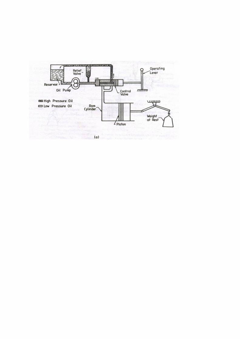
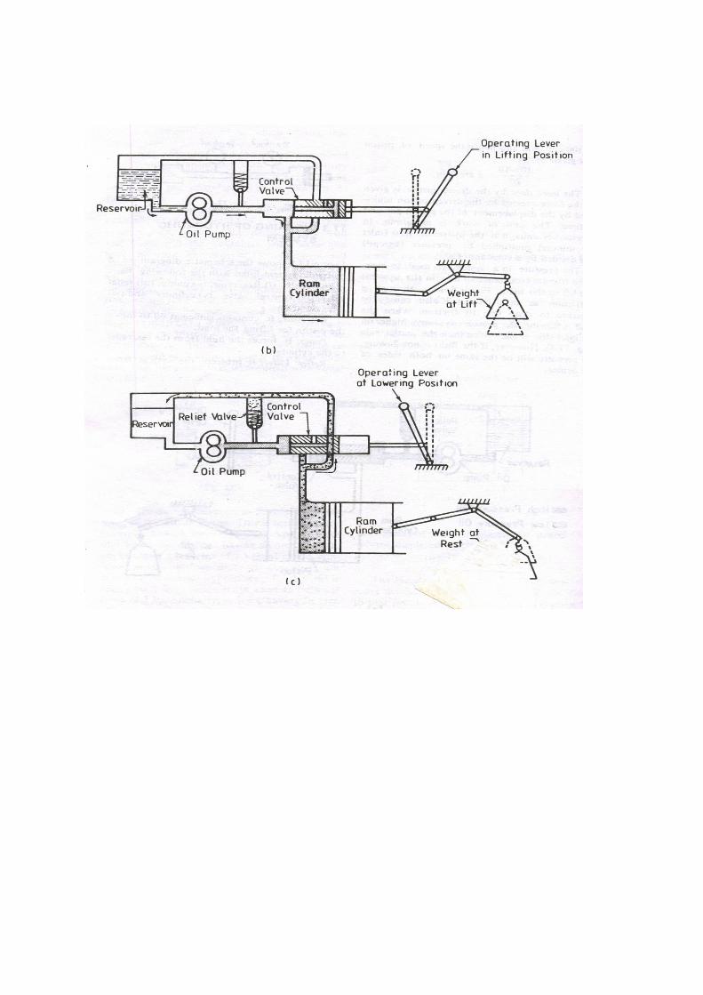
B. Explain the hydraulic system of a ttractor.
Hydraulic system of a tractor is considered to be a unit responsible for lifting and lowering the
agricultural implements. It also does many other important jobs.
In hydraulic system, the fluid is confined inside the cylinder and pipe lines. When pressure is
applied at any point, the force is transferred by the fluid throughout the system which is utilized to lift
the implements and do other works.
Working of Hydraulic system:
In the figure the schematic diagram of the hydraulic system with its basic components are
shown. Reservoir, pump, relief valve, control valve, cylinder and filter or strainer are the main
components.
Reservoir: It stores sufficient oil to move the piston inside the cylinder for lifting and lowering of
the implements and other loads.
Pump: It forces the fluid from the reservoir to the cylinder. It produces the required pressure
for the operations of the tractor. Usually rotor pumps like gear pump or other positive displacement
pumps are used for this purpose.
It protects the system from high pressure. The valve is set marginally higher than the maximum
working pressure. If the pressure increases above this point, the relief valve opens allowing the oil to
pass on to the reservoir. Also when the piston reaches the extreme position the relief valve opens and
by-passes the oil to the reservoir.
Control valve: The control valve is used to allow the operator to direct the flow of the oil either
from the pump to the cylinder or from the cylinder to the reservoir.
Control lever: The operational control lever for position control is fitted on the right hand side
of the driver. The tractor has four positions viz. lift, stop, lower and TCV. Apart from this separate
levers will be provided for draft control. The implement is connected to the tractor by hydraulic through
three point linkage, one top link and two bottom links. Bottom links are connected to the lift arms and
are directly mounted on a rock shaft which is further connected to the piston rod.
Any movement of the piston is transferred to the bottom links. The top link is used for
connecting the third hitch point of the implement and is adjustable for maintaining the implement lever
and suction angle.


![OPTICAL PROPERTIES · Piezoelectric 2(s E or E s) d α 10 – 103 pm/V [3 pm/V in quartz] actuators, sensors, transducers, motors, MEMS, energy harvesters Pyroelectric (DT 3E) p α](https://img.pdfslide.us/doc/110x75/607ab373621b70758013cea0/optical-properties-piezoelectric-2s-e-or-e-s-d-10-a-103-pmv-3-pmv-in-quartz.jpg)