Embed Size (px)
Citation preview

© 2014 WILEY-VCH Verlag GmbH & Co. KGaA, Weinheim 1193wileyonlinelibrary.com
FULL P
APER
Twisted Focusing of Optical Vortices with Broadband Flat Spiral Zone Plates
Hong Liu , Muhammad Q. Mehmood , Kun Huang , Lin Ke , Huapeng Ye , Patrice Genevet , Mingsheng Zhang , Aaron Danner , Swee Ping Yeo , Cheng-Wei Qiu ,* and Jinghua Teng*
H. Liu, L. Ke, J. Teng Institute of Materials Research and Engineering Agency for Science Technology and Research (A*STAR) 3 Research Link , Singapore 117602 E-mail: [email protected] M. Q. Mehmood, K. Huang, H. Ye, A. Danner, S. P. Yeo, C.-W. Qiu Department of Electrical and Computer Engineering National University of Singapore 4 Engineering Drive 3 , Singapore 117576 E-mail: [email protected] P. Genevet School of Engineering and Applied Sciences Harvard University Cambridge , MA 02138 , USA M. Zhang Data Storage Institute Agency for Science Technology and Research (A*STAR), DSI Building 5 Engineering Drive 1 , Singapore 117608
DOI: 10.1002/adom.201400315
1. Introduction
Intensive developments have shown that light’s orbital angular momentum (OAM) can be harnessed for a diver-sity of emerging applications, [ 1,2 ] which recently have been extended to optical communications. [ 3,4 ] From a fundamental perspective, optical vortex beams, e.g., the Lagurerre-Gaussian (LG) beam or Bessel beam, has annular transverse intensity
Recent developments have shown that light’s orbital angular momentum (OAM) can be harnessed for a diversity of emerging applications and generated by miniaturized OAM generators. Nanostructured fl at logarithmic-spiral zone plates (LSZPs) are proposed to produce as well as focus optical vortices with a long focal depth in the broadband visible range. Topologically breaking the in-plane symmetry, this nanoengineered LSZP continuously modulates both amplitude and phase in the diffraction fi eld to shape twisted focusing of the optical vortex beam, which is microscopically confi ned and spatially spiraling with variant crescent-shaped transverse intensity profi les. Owing to its rich structural degree of freedom upon aperiodic and continuously variant features, the LSZP provides a compact solution to generate and control optical vortices carrying scalable OAM and highly concentrated photons with a high transmis-sion effi ciency of ∼22%. This can offer new opportunities for 3D light shaping, optical manipulation, fl at optics, and photonics miniaturization and integration.
profi les and possesses an azimuthal phase dependence of exp �i ϕ( ) carrying a well-defi ned OAM of � −h per photon (where � is the topological charge indicating the winding number of helical wavefront, −h is the reduced Planck’s constant and ϕ is the azimuthal coordinate). [ 5 ] Naturally OAM relates to spatial fi eld distribution but is independent of the polarization states, which is an intriguing property to spur huge efforts to generate various optical vortices with well-developed and novel OAM generators for scrutination. For example, spatial light modulators, [ 3,4 ] holograms [ 6,7 ] and spiral phase plates [ 8,9 ] traditionally produce a typical case of LG beam, where in principle OAM can be boundlessly generated by these complex or bulky optical vortex generators. Recent achievements on plasmonic spiral vortex
lens, [ 10,11 ] annular-grating vortex emitter [ 12 ] and discrete devices such as metasurfaces [ 13,14 ] as well as topological nanoslits [ 15 ] have routed research trend to downsize structure to achieve controllable OAM at a small scale. From a technological point of view, all these miniaturized devices are polarization-sensitive due to their subwavelength-scale features. In contrast, spiral zone plates (SZP) as a polarization-insensitive vortex generator has been traditionally proposed to produce integral and frac-tional OAM carried by either isotropic optical vortices [ 16,17 ] or anisotropic vortex beams, [ 18 ] respectively. However, it is intrinsi-cally limited by its wavelength-dependent property. In context of light-matter interactions, spirals engineered at nanoscale, a typical class of deterministic aperiodic nanostructures, recently have stood out thanks to their structural complexity and vari-ability in comparison with periodical matters. [ 19 ] Therefore, undertaking exploration of miniaturized novel SZP has been motivated to reach for exceptional performance.
2. Results and Discussion
Here, we propose nanostructured logarithmic-spiral zone plates (LSZP) to generate as well as focus anisotropic optical vortices with long focal depth carrying scalable OAM, which is polarization insensitive in visible range through its amplitude modulation. Figure 1 schematically illustrates a single-armed LSZP (left-handed), a mirror image of its right-handed partner which can be mathematically interpreted in polar ( r , ϕ ) coordi-nates: ,r aeb= ϕ , where the radial coordinate is denoted by r and
Adv. Optical Mater. 2014, 2, 1193–1198
www.MaterialsViews.comwww.advopticalmat.de

1194 wileyonlinelibrary.com © 2014 WILEY-VCH Verlag GmbH & Co. KGaA, Weinheim
FULL
PAPER
FULL
PAPER
FULL
PAPER
the angular coordinate by ϕ . The radial factor a determines the initial radius whereas the azimuthal factor b controls the growth rate of rotation. Together, they govern the overall struc-tural compactness. In this case, the LSZP can be considered as a binary-amplitude mask which has negligible near-fi eld effects upon light passing through. [ 20 ] For an incident beam of elec-tric fi eld E ( r , ϕ ,0), the electric fi eld immediately after the LSZP can be interpreted as , ,0 ,E r T rϕ ϕ( ) ( )⋅ , where T ( r , ϕ ) denotes the transmission function of the structure. ρ is the radial dis-tance between a viewing point ( ρ , θ,z ) after the structure and the optical axis at the observation plane while θ is its azimuthal angle and z is the distance between the aperture plane and the observation plane; in addition, R denotes the distance between two points. To calculate the light propagation in free space, Rayleigh-Sommerfeld diffraction is applied to approximate the meso-fi eld (within several tens of wavelengths from the struc-ture surface). [ 21 ] For the case of multi-armed LSZP, its meso-fi eld diffraction can be attained by coherent superposition of diffractions from individual arms. The electric fi eld of light is given by:
, ,
12
, ,0exp
1
20
3
1
4
1
2
E z
E rz iknR
R
iknR
rdrd
r
r
m m
m
∫∫∑ρ θ
πϕ
ϕ
( )( )= −
⋅⎛⎝⎜
−⎛⎝⎜
⎞⎠⎟
⎞⎠⎟
π
=
(1)
where 2 cos2 2 2 2R z r rρ ρ ϕ θ( )= + + − − , m is the arm number ascending from inner to outer), r m1 = [( m -1) t 0 +( m -1) g 0 + a ]e bϕ and r m2 = [ mt 0 +( m -1) g 0 + a ]e bϕ ; t 0 and g 0 denote the arm width and separation at ϕ = 0, respectively; k is the wave vector of elec-tric fi eld and n is the refractive index of the meso-regime (with n = 1 in this case). Therefore, the diffraction fi eld inclusive of spatial intensity and phase profi les of transmitted light can be acquired from Equation ( 1) .
Unlike Bessel and LG beams, the diffractive beam in this case is a non-paraxial beam carrying OAM per photon and top-ological charge with different values. To reveal the vortex phase
in the diffraction fi eld E ( ρ , θ,z ), the topolog-ical charge L is defi ned as. [ 22 ]
12 �L d
C∫πχ=
(2)
where C refers to a closed curve (its radius is 1 um in this case) and the phase item χ = arg < E ( ρ , θ,z )>. For simplifi cation and miniaturization, only the integer topological charges ( L = 1∼4 from P 1 to P 4 ) will be exam-pled for further study. Plotted in Figure 2 a are the diffracting fi elds of corresponding LSZPs. Their phase profi les explicitly show the respective integer values of topological charges, theoretically manifesting the exist-ence of optical vortex beam produced by the LSZP. Since topological charge addressing is demonstrated merely with a single arm, the
beam tends to diverge as � rises (and even splits in half at P 4 ) based on the resulted transverse intensity profi les. It indicates that single-armed LSZP fails to effectively retain the focusing during long-range propagation.
In order to enhance the focusing performance, multiple-armed ( m = 4) LSZP at P 4 has been theoretically modeled to gain physical insight into its diffraction fi eld by probing the correlation between the geometries of structure and transmission. Depicted in Figure 2 b are the schematics of the single- and 4-armed LSZPs and their intensity profi les produced at the selected distances ( z = 6.25 µm, 15 µm, and 21 µm). With the same structural factors ( a , b, t ), the 4-armed spiral exhibits much superior focusing ability to its single-armed opponent in terms of photon confi nement along long-range propagation. It validates that more arms strengthen the constructive interference to enhance focusing perfor-mance of the LSZP, which is similar to Fresnel lens and zone plates.
Upon a normal incident illumination (λ = 632.8 nm) from the backside, the spatial intensity distributions of the 4-armed LSZP are analytically plotted in Figure 3 . Centered on the optical axis, oblique transmission rays are visualized along the x−z plane as shown in Figure 3 a. In contrast, zero intensity (dark center) has been attained along the beam-axis. To fur-ther demonstrate the spatial intensity distribution, a summary of pseudo-color intensity maps over selected x − y transverse planes at different heights along the propagation direction ( z ) are depicted in Figure 3 b. As diffracted light propagates, foci of crescent transverse profi les are anisotropically formed as well as confi ned in a microscopic circular area of a diameter less than ≈3 µm from the initialization at z ≈ 4 µm (≈6.3λ) till a distance of about 32 µm, beyond which a continual decay of photon density and gradually decreased confi nement of trans-verse intensity profi le are observed. A relatively long depth of focus approximates 44λ along which the transverse radii of foci gradually rise with a common feature of dark center. Up to this point, an interesting scenario intuitively comes about where the LSZP produces and focuses an optical beam with left-handed twisting around its beam-center in a conical trajectory when travelling in free space.
Adv. Optical Mater. 2014, 2, 1193–1198
www.MaterialsViews.comwww.advopticalmat.de
Figure 1. Schematic illustration of the LSZP and a cylindrical coordinate setup for the meso-fi eld calculation to derive an analytical model. The inset shows its initial arm width t = 350 nm ( ϕ = 0) with 3π rotation angle.

1195wileyonlinelibrary.com© 2014 WILEY-VCH Verlag GmbH & Co. KGaA, Weinheim
FULL P
APER
FULL P
APER
FULL P
APER
The spatial intensity distribution is explicitly visualized by the FDTD-generated three-dimensional normalized maximum intensity | E max | 2 depicted in Figure 4 a. It shows the generated beam continuously twists around its beam-axis and alters its intensity during propagation. Its projection onto the trans-verse plane describes a logarithmic-spiral path, indicating that actually a spiraling optical beam is shaped due to the twisted
focusing of the LSZP. Figure 4 b plots the computed Poynting vector S corresponding to the maximum intensity, showing that the resultant Poynting vectors are directed tangentially compel-ling a conically spiraling energy fl ow around the beam axis, which is due to the contributions from the azimuthal compo-nent S θ and the longitudinal component S z . Hence, the pro-duced beam theoretically satisfi es the fundamental criteria of
Adv. Optical Mater. 2014, 2, 1193–1198
www.MaterialsViews.comwww.advopticalmat.de
Figure 2. Scaling of topological charge carried by the optical beam. (a) A summary of different LSZPs constructed by the scaling factors of four exam-ples and their corresponding phase and intensity profi les ( z = 10 µm). The scaling factors were exampled as follows: P 1 ( a = 4.2 µm, b = 0.04); P 2 ( a = 4.31 µm, b = 0.053); P 3 ( a = 4.45 µm, b = 0.07); P 4 ( a = 4.59 µm, b = 0.0875). (b) FDTD analysis and comparison of arm number effect on focusing performance at the meso-fi eld between the single- and 4-armed LSZP structures (P 4 ).
Figure 3. The analytical pseudo-color intensity maps of spatial transmission along the optical axis above the 4-armed LSZP structure. The initial sepa-ration ( g 0 ) between the arms is 350 nm (equal to t 0 ). (a) The intensity profi les of x−z plane across the spiral center (16 × 35 µm 2 ). The bottom panel shows the intensity image (16 × 16 µm 2 ) at the surface ( z = 0). (b) A summary of the x−y plane intensity profi les over an area of 4 × 4 µm 2 at selected heights. The color scale in each image is normalized to its respective maximum intensity in order to facilitate distinct visualization.

1196 wileyonlinelibrary.com © 2014 WILEY-VCH Verlag GmbH & Co. KGaA, Weinheim
FULL
PAPER
FULL
PAPER
FULL
PAPER
an OAM-carried vortex beam, which is signifi ed by its central dark region and spiraling S around its axis. [ 23 ]
Figure 5 a schematically depicts the optical characterization using a photon scanning tunneling microscope (PSTM: Alpha 300S, WITec GmbH) illuminated by a linearly polarized (LP) continuous wave He-Ne laser. The scanning electron micro-scopy (SEM) image (the inset) shows the LSZP specimen embedded in a 100-nm thick chromium fi lm on a quartz sub-strate via electron beam lithography. A summary of the meas-ured pseudo-color intensity maps depicted in Figures 5 b & 5 c demonstrate good agreement with the theoretical descriptions. Based on the above studies, the origin of focusing cum twisting can be qualitatively elaborated as following. Upon illumination, light passing through the spiral will be imposed by the geo-metrical phase of each individual arm. The optical path length of each diffractive beam is uniquely modulated by the variant geometry of the LSZP leading to phase aberration. Such phase aberration accumulates along propagation, which is eventually accountable for exponential-angular-dependent constructive interference to consecutively form twisted focusing as well as vary intensity in free space. Simultaneously, the propagation vectors
�k( ) of diffracted beams spatially superimpose at cor-
responding locations, which governs the twisting of the beam around the z -axis following a conical trajectory. Hence, the focusing-cum-twisting phenomenon can be qualitatively attrib-uted to the in-plane symmetry breaking intrinsically deter-mined by the logarithmic-spiral algorithm. A detailed anal-ysis given in the Supporting Information (SI) shows that this phenomenon is wavelength-dependent due to the broadband behavior of the device. Note this LSZP exponentially grows its features (widths and separations) with the angle over a scale from sub- (≈0.55λ) to slightly above one-wavelength (≈1.27λ). Within such a scale, the subwavelength control of wavefronts
via metasurfaces has been demonstrated in a rather broad range of wavelength upon acquiring new degree of freedom. [ 24 ] Therefore, it is understandable that this LSZP is also operate-able under broadband illumination from a supercontinuum laser source (Fianium, FemtoPower 1060, wavelength ranges approximately from 420 nm∼2 µm), as shown in the Supple-mentary Movies.
To measure the phase profi le, a Mach-Zehnder interfer-ometer was set up to interfer the spiraling beam with a co-propagating Gaussian beam. Figure 6 a presents the FDTD-generated results for the helical phase profi le of optical vortex beam with the topological charge of L = +4 and phase shift ranging from 0 to 8π (with an incremental step of 2π). Under spherical wave interference, spiral wavefront of this vortex beam was manifested by four anti-clockwise twisted fringes as shown in Figure 6 b, indicating a topological charge of L = +4. The simulated intensity distribution of the interference pat-tern with a close-up visualization at the interference center completely reconstructs the spiral optical wavefronts as shown in Figure 6 c. Intensity discrepancy of those 4 spiral fringes between Figures 6 b and 6c can be observed. It can be attrib-uted to the limited degree of coherence of light source and narrow tuning range of the optical path for both the sample and reference beams due to the optical setup with the PSTM system, which makes it very challenging to achieve a perfectly matched experimental image.
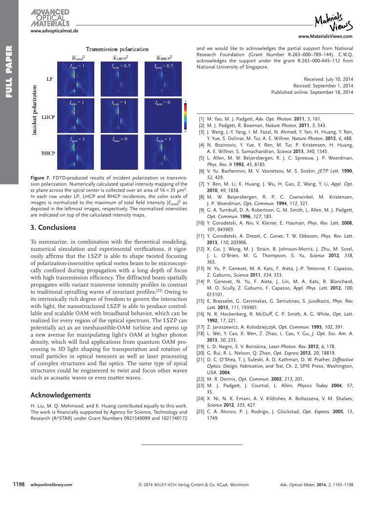
In addition, polarization dependence of twisted focusing via this LSZP was also scrutinized under LP, left- & right-handed circularly polarized (LHCP and RHCP) incidences, respectively. Figure 7 shows the FDTD results, which is in good agreement with experimental results. Under either LHCP or RHCP incidences, the transmission always exhibits the same polarization state; i.e., LHCP incidence yields LHCP
Adv. Optical Mater. 2014, 2, 1193–1198
www.MaterialsViews.comwww.advopticalmat.de
Figure 4. FDTD analysis of spatial profi le of the maximum intensity | E max | 2 and the corresponding transmitted energy fl ux (Poynting vector). (a) Numeri-cally calculated three-dimensional ( xyz ) spatial profi le of | E max | 2 above the structure surface. The bottom panel shows its projection onto the xy plane. The color scale is normalized to its respective maximum intensity. (b) Numerically calculated Poynting vectors of the diffracted optical beam are directed along a conical trajectory. Its projection onto the xy plane showing the transverse part ( x & y components) is depicted in the bottom panel.

1197wileyonlinelibrary.com© 2014 WILEY-VCH Verlag GmbH & Co. KGaA, Weinheim
FULL P
APER
FULL P
APER
FULL P
APER
Adv. Optical Mater. 2014, 2, 1193–1198
www.MaterialsViews.comwww.advopticalmat.de
transmission while RHCP incidence produces RHCP trans-mission with equal intensities measured in both cases. In contrast, under LP incidence, the transmitted beam simulta-neously comprises LHCP and RHCP beams with intensities equal to the half of | E total | 2 . It can be explained that this LSZP varies its arm width from subwavelength (inner) to above-one-wavelength scale (outer). The transmission from subwave-length features is polarization sensitive, which has been well verifi ed by quite a few reported studies. However, in this case,
the transmitted beam from the features of above-one-wave-length scale is insensitive to polarization states, which domi-nates the diffraction fi eld. Therefore, the overall transmission of this LSZP exhibits polarization-insensitivity, which is domi-nated by the diffraction from large feature (above-wavelength scale) over than that from small feature (sub-wavelength scale). A high transmission effi ciency of about 22% has been experimentally measured, which is identical to the analytical result as detailed in the SI.
Figure 5. Characterization of the twisted focusing of optical vortex beam produced by the 4-armed LSZP. (a) Experimental setup and the SEM image of the fabricated specimen (the inset). (b) The intensity mapping of x−z plane measured across the spiral center via a depth scan (16 × 35 µm 2 ). The inset (bottom panel) shows the intensity image (16 × 16 µm 2 ) at the surface, which is taken at the image plane of the objective lens ( z = 0). (c) A summary of the x−y plane intensity maps measured over an area of 3 × 3 µm 2 at selected heights above the surface. The color scale in each image is normalized to its respective maximum intensity in order to facilitate distinct visualization.
Figure 6. Computational and experimental phase profi les reveal by interference. (a) FDTD-produced helical phase profi le at the center of the optical vortex beam in a circular area of 3-µm diameter with a topological charge L = +4. (b) Measured 4-spiral pattern with a topological charge L = +4. In contrast to the bright fringes, the core region exhibits a much lower intensity and becomes undetectable by the CCD camera. (c) FDTD-produced 4-spiral pattern under spherical wave interference at the center of a circular area with a diameter of about 4 µm, which is well reconstructed with reference to experiment.
1198 wileyonlinelibrary.com © 2014 WILEY-VCH Verlag GmbH & Co. KGaA, Weinheim
FULL
PAPER
FULL
PAPER
FULL
PAPER
Adv. Optical Mater. 2014, 2, 1193–1198
www.MaterialsViews.comwww.advopticalmat.de
3. Conclusions
To summarize, in combination with the theoretical modeling, numerical simulation and experimental verifi cations, it rigor-ously affi rms that the LSZP is able to shape twisted focusing of polarization-insensitive optical vortex beam to be microscopi-cally confi ned during propagation with a long depth of focus with high transmission effi ciency. The diffracted beam spatially propagates with variant transverse intensity profi les in contrast to traditional spiralling waves of invariant profi les. [ 25 ] Owing to its intrinsically rich degree of freedom to govern the interaction with light, the nanostructured LSZP is able to produce control-lable and scalable OAM with broadband behavior, which can be realized for every region of the optical spectrum. The LSZP can potentially act as an inexhaustible-OAM turbine and opens up a new avenue for manipulating light’s OAM at higher photon density, which will fi nd applications from quantum OAM pro-cessing to 3D light shaping for transportation and rotation of small particles in optical tweezers as well as laser processing of complex structures and fl at optics. The same type of spiral structures could be engineered to twist and focus other waves such as acoustic waves or even matter waves.
Acknowledgements H. Liu, M. Q. Mehmood, and K. Huang contributed equally to this work. The work is fi nancially supported by Agency for Science, Technology and Research (A*STAR) under Grant Numbers 0921540099 and 1021740172
and we would like to acknowledges the partial support from National Research Foundation (Grant Number R-263–000–789–144). C.W.Q. acknowledges the support under the grant R-263–000-A45–112 from National University of Singapore.
Received: July 10, 2014 Revised: September 1, 2014
Published online: September 18, 2014
[1] M. Yao , M. J. Padgett , Adv. Opt. Photon. 2011 , 3 , 161 . [2] M. J. Padgett , R. Bowman , Nature Photon. 2011 , 5 , 343 . [3] J. Wang , J.-Y. Yang , I. M. Fazal , N. Ahmed , Y. Yan , H. Huang , Y. Ren ,
Y. Yue , S. Dolinar , M. Tur , A. E. Willner , Nature Photon. 2012 , 6 , 488 . [4] N. Bozinovic , Y. Yue , Y. Ren , M. Tur , P. Kristensen , H. Huang ,
A. E. Willner , S. Samachandran , Science 2013 , 340 , 1545 . [5] L. Allen , M. W. Beijersbergen , R. J. C. Spreeuw , J. P. Woerdman ,
Phys. Rev. A 1992 , 45 , 8185 . [6] V. Yu. Bazhennov , M. V. Vasnetsov , M. S. Soskin , JETP Lett. 1990 ,
52 , 429 . [7] Y. Ren , M. Li , K. Huang , J. Wu , H. Gao , Z. Wang , Y. Li , Appl. Opt.
2010 , 49 , 1838 . [8] M. W. Beijersbergen , R. P. C. Coerwinkel , M. Kristensen ,
J. P. Woerdman , Opt. Commun. 1994 , 112 , 321 . [9] G. A. Turnbull , D. A. Robertson , G. M. Smith , L. Allen , M. J. Padgett ,
Opt. Commun. 1996 , 127 , 183 . [10] Y. Gorodetski , A. Niv , V. Kleiner , E. Hasman , Phys. Rev. Lett. 2008 ,
101 , 043903 . [11] Y. Gorodetski , A. Drezel , C. Genet , T. W. Ebbesen , Phys. Rev. Lett.
2013 , 110 , 203906 . [12] X. Cai , J. Wang , M. J. Strain , B. Johnson-Morris , J. Zhu , M. Sorel ,
J. L. O’Brien , M. G. Thompson , S. Yu , Science 2012 , 338 , 363 .
[13] N. Yu , P. Genevet , M. A. Kats , F. Aieta , J.-P. Tetienne , F. Capasso , Z. Gaburro , Science 2011 , 334 , 333 .
[14] P. Genevet , N. Yu , F. Aieta , J. Lin , M. A. Kats , R. Blanchard , M. O. Scully , Z. Gaburro , F. Capasso , Appl. Phys. Lett. 2012 , 100 , 013101 .
[15] E. Brasselet , G. Gervinskas , G. Seniutinas , S. Juodkazis , Phys. Rev. Lett. 2013 , 111 , 193901 .
[16] N. R. Heckenberg , R. McDuff , C. P. Smith , A. G. White , Opt. Lett. 1992 , 17 , 221 .
[17] Z. Jaroszewicz , A. Kolodziejczyk , Opt. Commun. 1993 , 102 , 391 . [18] L. Wei , Y. Cao , X. Wen , Z. Zhao , L. Cao , Y. Gu , J. Opt. Soc. Am. A.
2013 , 30 , 233 . [19] L. D. Negro , S. V. Boriskina , Laser Photon. Rev. 2012 , 6 , 178 . [20] G. Rui , R. L. Nelson , Q. Zhan , Opt. Express 2012 , 20 , 18819 . [21] D. C. O’Shea , T. J. Suleski , A. D. Kathman , D. W. Prather , Diffractive
Optics: Design, Fabrication, and Test , Ch. 2, SPIE Press , Washington, USA 2004 .
[22] M. R. Dennis , Opt. Commun. 2002 , 213 , 201 . [23] M. J. Padgett , J. Courtial , L. Allen , Physics Today 2004 , 57 ,
35 . [24] X. Ni , N. K. Emani , A. V. Kildishev , A. Boltasseva , V. M. Shalaev ,
Science 2012 , 335 , 427 . [25] C. A. Alonzo , P. J. Rodrigo , J. Glückstad , Opt. Express. 2005 , 13 ,
1749 .
Figure 7. FDTD-produced results of incident polarization vs transmis-sion polarization. Numerically calculated spatial intensity mapping of the xz plane across the spiral center is collected over an area of 16 × 35 µm 2 . In each row under LP, LHCP and RHCP incidences, the color scale of images is normalized to the maximum of total fi eld intensity | E total | 2 as depicted in the leftmost images, respectively. The normalized intensities are indicated on top of the calculated intensity maps.