Embed Size (px)
Citation preview
Engineered cooling solutions for all applications
Email:
Website:
Website:
Motivair TM
www.chilleddoor.com
www.motivaircorp.com
INSTALLATION <> OPERATION <> MAINTENANCE GUIDE
Cooling Distribution Unit
Model: MCDU‐75‐6‐60
Motivair Corporation85 Woodridge Drive Amherst, NY 14228 716‐691‐9222 (Ph) 716‐691‐9229 (fax)
CDU IOM Rev1.0
Product Standards and ComplianceAll products conform to industry standards and ratings; contact Motivair for a complete list
and certificates for specific models.
The manufacturer shall not be liable for any damages resulting from misapplication or misuse
of its products.
ATTENTION
Read this page before proceeding
ABOUT THIS DOCUMENT
Cooling Distribution Unit
This document may be updated without notice at any time. Motivair reserves the right to
update and or change product specifications and performance without notice as design
improvements occur. Please contact the factory to ensure that your version is the most up to
date.
Disclaimer
Page 2
Section 1 SAFETY INSTRUCTIONS
General Safety 5
Owners Responsibility 5
Installation / Handling 5
Application 5
Electrical Warning 5
Section 2 GENERAL DESCRIPTIONGeneral Product Description 6
Technical Data 6
Section 3 TECHNICAL DATAElectrical Data 7
Design Capacities 7
Dimensional Drawings 8
P&ID 9Primary Loop 10
Secondary Loop 10
Section 4 INSTALLATIONReceiving and Uncrating 11Floor Preparation 11
Locating and Positioning 12
Electrical 12Piping Connections 12‐15
Cleaning and Flushing 15
Water Quality 16Filling and Venting 17
Section 5 COMMISSIONINGPre‐commissioning Checks 18
Commissioning 19
Description/Sequence of Operation 19‐20
Section 6 OPERATIONPLC Controller HMI Introduction 21PLC Controller Parameter Screens 22
Set Points and Operation 23‐25
Alarm Acknowledgement 26
CDU IOM Rev1.0
CONTENTS
Cooling Distribution Unit
Page 3
Section 7 TROUBLESHOOTING
General 27
Non‐Alarms 27Alarms 28
Section 8 MAINTENANCEScheduled Maintenance 29
Section 9 SPARE PARTSParts List 30‐31
Section 10 DOCUMENTS AND TABLESBMS Table 32‐34
Electrical Schematics 35‐37
Section 11 SUPPORT AND WARRANTYFactory Support Contact Info 38
Notes 39
Section 12 APPENDIX Start Up Report A1‐A2
CDU IOM Rev1.0
Cooling Distribution Unit
Page 4
Section 1
CDU IOM Rev1.0
Cooling Distribution Unit
This unit must only be used in the application for which it was designed. Do not use this
product in any hazardous environment.
Application
Electrical
WARNING – This unit is powered by HIGH VOLTAGE. Serious injury or death can occur. Power
being supplied to the unit must be isolated with an electrical disconnect. Any and all
electrical connections or procedures should only be performed by a certified electrician. All
electrical work or procedures should be in accordance with local, state and national electrical
codes and regulations. NEVER make any electrical connections to this unit unless the power
supply is OFF at the power supply disconnect switch.
This equipment must be installed, maintained and operated by a person or persons qualified
for this equipment. This system contains water circulation equipment and electrical
components. The person most suited to perform any operations or service on this equipment
is a qualified industrial technician and or electrician with experience and qualifications to
work with water systems and electrical systems.
Owner's Responsibility
Installation and operation should always be conducted in compliance with local, state and
national codes and industry best practices. When moving or installing the unit, CAUTION
must be observed at all times to ensure the safety and well being of personnel. Follow all
local, State and national codes for moving equipment. Only appropriate and approved
moving equipment should be used.
Installation
Operation of this equipment involves potentially lethal dangers (HIGH VOLTAGE POWER and
High water Pressures.) Therefore, ALL safety precautions and warnings described in this
manual must be precisely observed. Failure to follow these precautions and warnings can
result in severe or fatal injury
WARNING
Temperature control equipment, pump stations and electrical devices contained in this
system present various electrical, mechanical, sound and vibration hazards. For this reason,
operation and service procedures should only ever be performed by qualified, fully trained
and technically competent personnel.
This equipment contains:
• High pressure water generated by the system
• Electrically energized components
• Hot pipes and heat exchangers
• Rotating parts such as pump impellers, wheels and valves.
General Safety
SAFETY INSTRUCTIONS
Page 5
Section 2
CDU IOM Rev1.0
GENERAL DESCRIPTION
Cooling Distribution Unit
General Product Description
Technical Data
Technical Data such as pump curves, electrical loads and sound data for any specific CDU that
is not included in this general manual may be obtained on the CDU nameplate or from the
product specification or submittal. Consult Motivair with any questions or document requests
The Cooling Distribution Unit (CDU) is designed for use with Motivair Chilled Doors and other
approved distribution systems and equipment in a data center environment. The CDU
includes a plate heat exchanger that creates a divide between customer supplied cold water
(Primary Loop) and a separate cooling loop that feeds Chilled Doors (Secondary Loop). The
Secondary Loop flow and pressure is created by the CDU pumps and valve assemblies. The
Secondary Loop is always controlled to operate above room dew point to avoid condensation
on the Chilled Door coils.
The Primary Loop water system should always have a micron filtration level of less than 500
microns. The water supply can be from various sources such as a chiller plant. Clean and
filtered water and or glycol is the sole responsibility of the user. Large amounts of debris or
particulate can reduce efficiency or plug the CDU heat exchanger.
Heat extracted from the Chilled Doors is transferred to the CDU heat exchanger where the
heat is exchanged to the Primary Loop and removed.
Various set points and alarms can be monitored and controlled within the CDU. These can be
adjusted by the operator via an integrated PLC.
Cooling Distribution Units can be built in various configurations. Make sure to check specific
product specifications and design criteria for each specific CDU. Consult Motivair with any
questions.
Page 6
Section 3
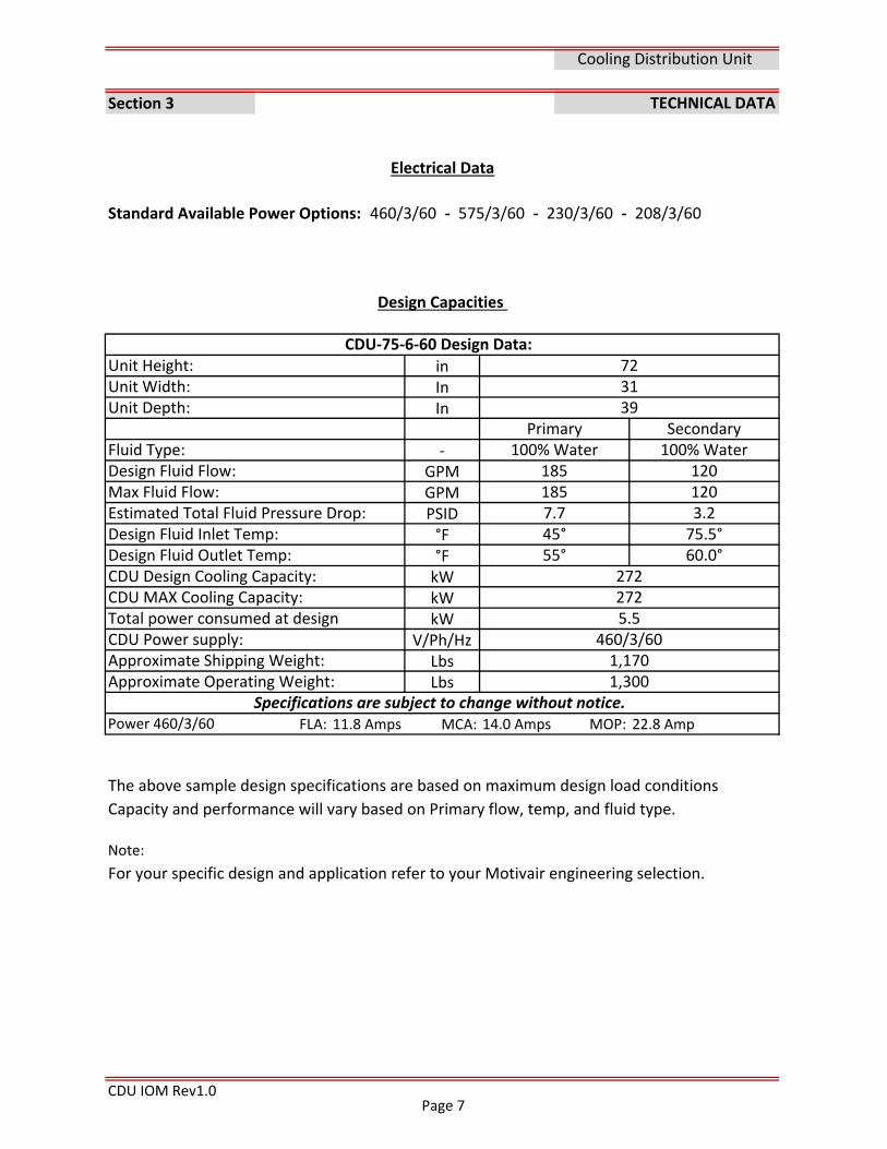
Standard Available Power Options: 460/3/60 ‐ 575/3/60 ‐ 230/3/60 ‐ 208/3/60
inInIn
‐GPMGPMPSID°F°FkWkWkW
V/Ph/HzLbsLbs
FLA: 11.8 Amps MCA: 14.0 Amps MOP: 22.8 Amp
The above sample design specifications are based on maximum design load conditions
Capacity and performance will vary based on Primary flow, temp, and fluid type.
Note:
For your specific design and application refer to your Motivair engineering selection.
CDU IOM Rev1.0
TECHNICAL DATA
CDU‐75‐6‐60 Design Data:
Primary
Estimated Total Fluid Pressure Drop:
72
CDU MAX Cooling Capacity:
185
Unit Height:Unit Width:
39
100% Water
Specifications are subject to change without notice.
Unit Depth:
Fluid Type:Design Fluid Flow:Max Fluid Flow:
Design Fluid Inlet Temp:Design Fluid Outlet Temp:
272272
Approximate Operating Weight:
CDU Design Cooling Capacity:
Secondary
Cooling Distribution Unit
Electrical Data
Total power consumed at design CDU Power supply:Approximate Shipping Weight: 1,170
Power 460/3/60
Design Capacities
7.745°55°
100% Water1201203.275.5°60.0°
31
185
5.5460/3/60
1,300
Page 7
CDU IOM Rev1.0
Cooling Distribution Unit
Page 8
CDU IOM Rev1.0
Cooling Distribution Unit
Page 9
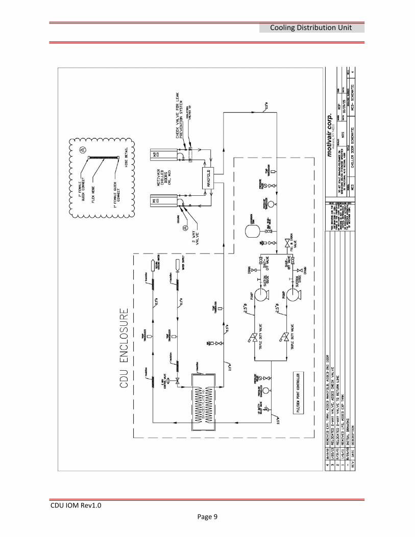
Primary Loop
Secondary Loop
CDU IOM Rev1.0
The Secondary Loop connections are made on the underside of the CDU (bottom connections
for raised floor installation). These connections can be either NPT or sweat connections and
can be specified at the time of order. These Secondary In and Secondary Out connections
typically run to and from a “supply and return header” that can be mounted under the raised
floor by the installer. Connections between the CDU and the “Supply and return header” are
made by the installer. This piping should be self supporting as the CDU is not designed for
any external pipe loads.
The Secondary Loop should be filled with clean softened water. Consult Chilled Door
specification for water details.
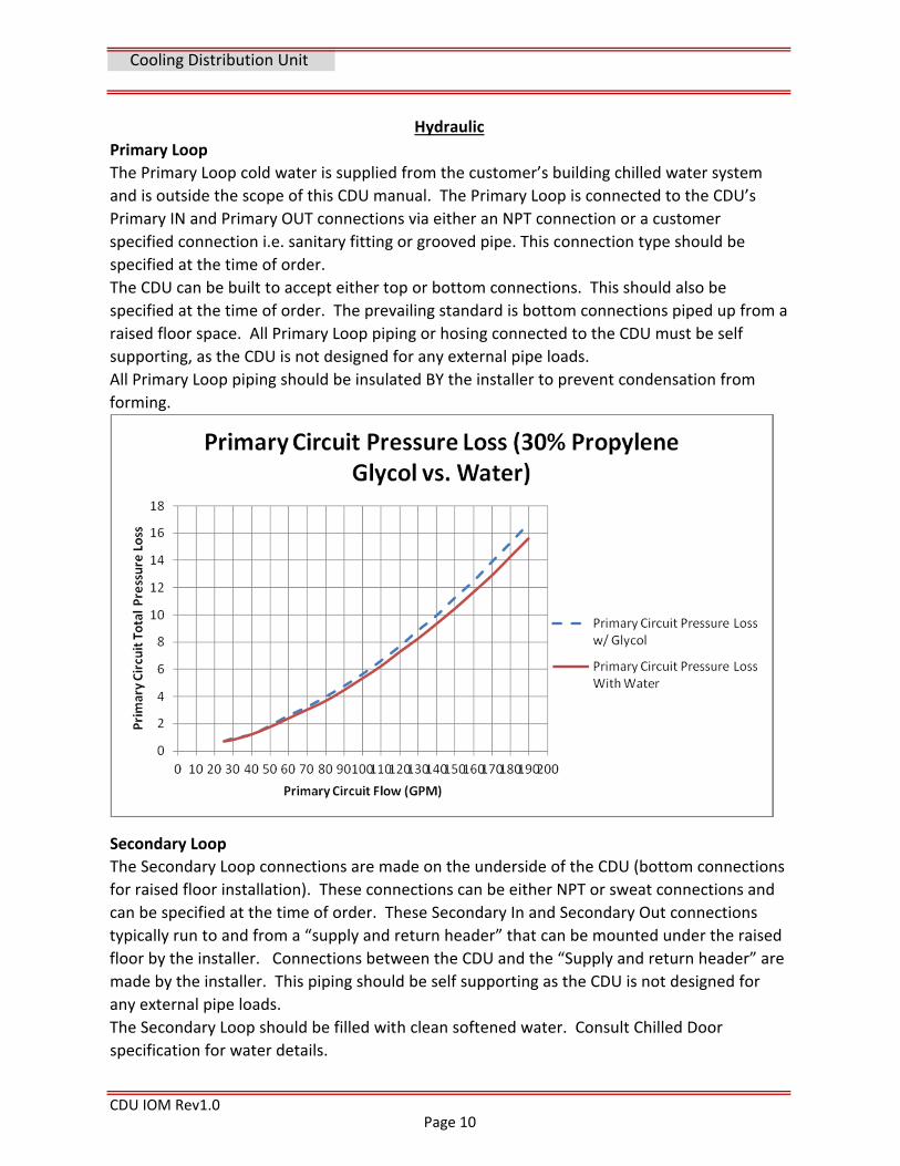
Hydraulic
The Primary Loop cold water is supplied from the customer’s building chilled water system
and is outside the scope of this CDU manual. The Primary Loop is connected to the CDU’s
Primary IN and Primary OUT connections via either an NPT connection or a customer
specified connection i.e. sanitary fitting or grooved pipe. This connection type should be
specified at the time of order.
The CDU can be built to accept either top or bottom connections. This should also be
specified at the time of order. The prevailing standard is bottom connections piped up from a
raised floor space. All Primary Loop piping or hosing connected to the CDU must be self
supporting, as the CDU is not designed for any external pipe loads.
All Primary Loop piping should be insulated BY the installer to prevent condensation from
forming.
Cooling Distribution Unit
Page 10
Section 4
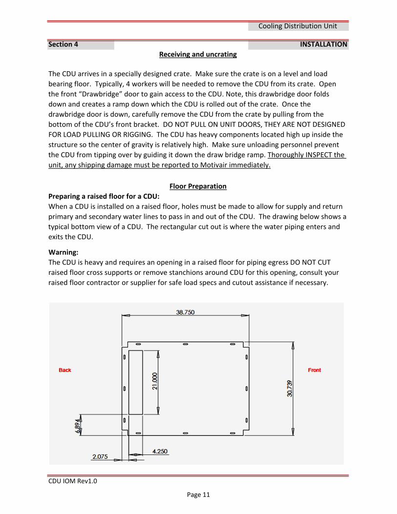
Warning:
CDU IOM Rev1.0
INSTALLATION
Cooling Distribution Unit
Receiving and uncrating
The CDU is heavy and requires an opening in a raised floor for piping egress DO NOT CUT
raised floor cross supports or remove stanchions around CDU for this opening, consult your
raised floor contractor or supplier for safe load specs and cutout assistance if necessary.
Floor Preparation
Preparing a raised floor for a CDU:
When a CDU is installed on a raised floor, holes must be made to allow for supply and return
primary and secondary water lines to pass in and out of the CDU. The drawing below shows a
typical bottom view of a CDU. The rectangular cut out is where the water piping enters and
exits the CDU.
The CDU arrives in a specially designed crate. Make sure the crate is on a level and load
bearing floor. Typically, 4 workers will be needed to remove the CDU from its crate. Open
the front “Drawbridge” door to gain access to the CDU. Note, this drawbridge door folds
down and creates a ramp down which the CDU is rolled out of the crate. Once the
drawbridge door is down, carefully remove the CDU from the crate by pulling from the
bottom of the CDU’s front bracket. DO NOT PULL ON UNIT DOORS, THEY ARE NOT DESIGNED
FOR LOAD PULLING OR RIGGING. The CDU has heavy components located high up inside the
structure so the center of gravity is relatively high. Make sure unloading personnel prevent
the CDU from tipping over by guiding it down the draw bridge ramp. Thoroughly INSPECT the
unit, any shipping damage must be reported to Motivair immediately.
Page 11
CDU IOM Rev1.0
Control wiring: The RH% ‐ dew point sensor located below the control panel can be relocated
(wall mount) if CDU is not installed in the conditioned space. Relocating will require
extending a 4 conductor 18ga wire to the space. BMS wiring is also required per options
installed either IP network cable or shielded 3 wire.
Cooling Distribution Unit
Locating and positioning
Position the CDU on a smooth level floor (top Feed units). Bottom feed units typically will
need to be installed on 12” raised floor or higher to allow for pipe connections to be made to
the underside of the CDU. Once in position, there are leveling feet that MUST be adjusted to
ensure a stable, level operating platform. DO NOT LEAVE ON WHEELS. There are openings in
the bottom of the CDU to allow for IN/OUT Primary piping Connections and IN/OUT
secondary piping connections, the floor cutout should be aligned with CDU opening.
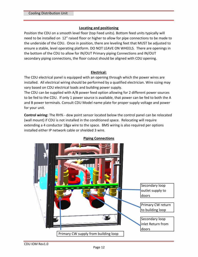
Primary CW supply from building loop
Primary CW return
to building loop
Secondary loop
outlet supply to
doors
Electrical:
The CDU electrical panel is equipped with an opening through which the power wires are
installed. All electrical wiring should be performed by a qualified electrician. Wire sizing may
vary based on CDU electrical loads and building power supply.
The CDU can be supplied with A/B power feed option allowing for 2 different power sources
to be fed to the CDU. If only 1 power source is available, that power can be fed to both the A
and B power terminals. Consult CDU Model name plate for proper supply voltage and power
for your unit.
Piping Connections
Secondary loop
inlet Return from
doors
Page 12
CDU IOM Rev1.0
Cooling Distribution Unit
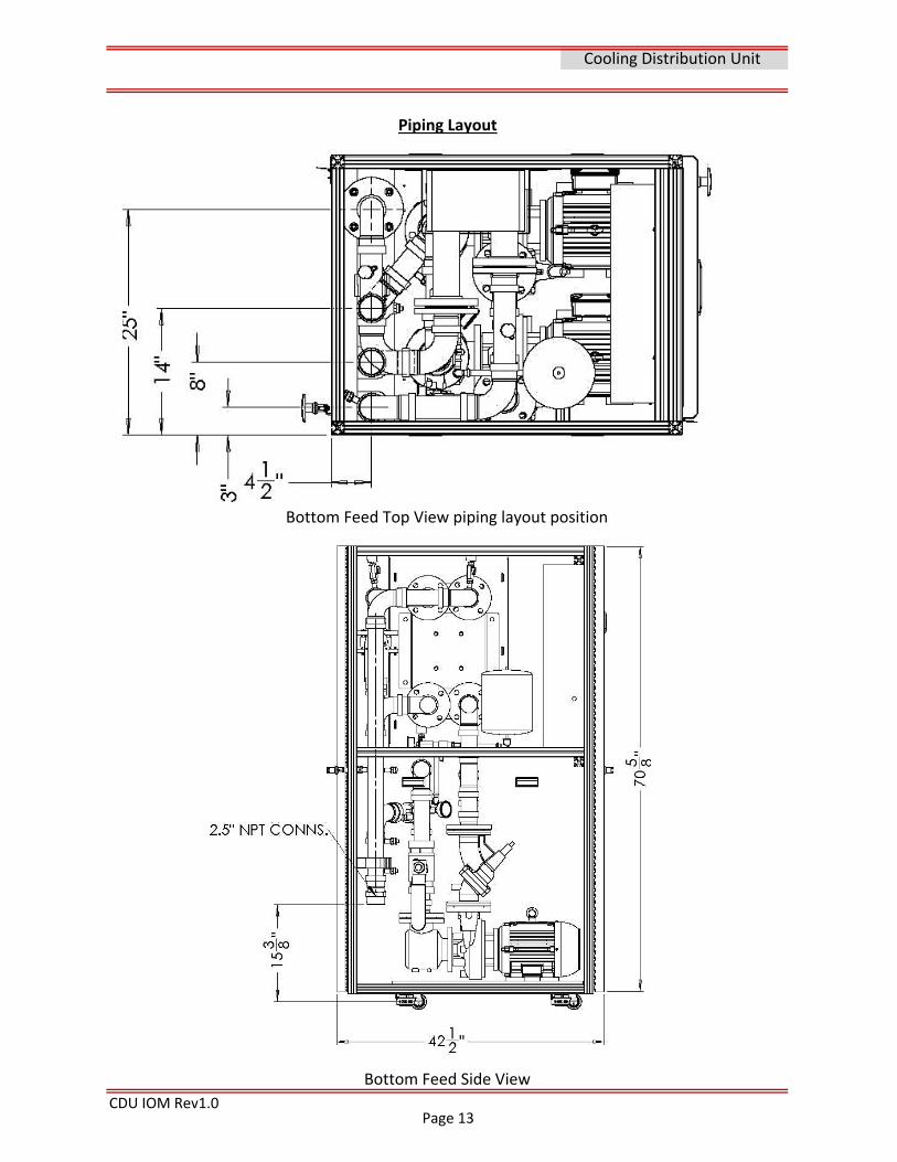
Bottom Feed Top View piping layout position
Bottom Feed Side View
Piping Layout
Page 13
CDU IOM Rev1.0
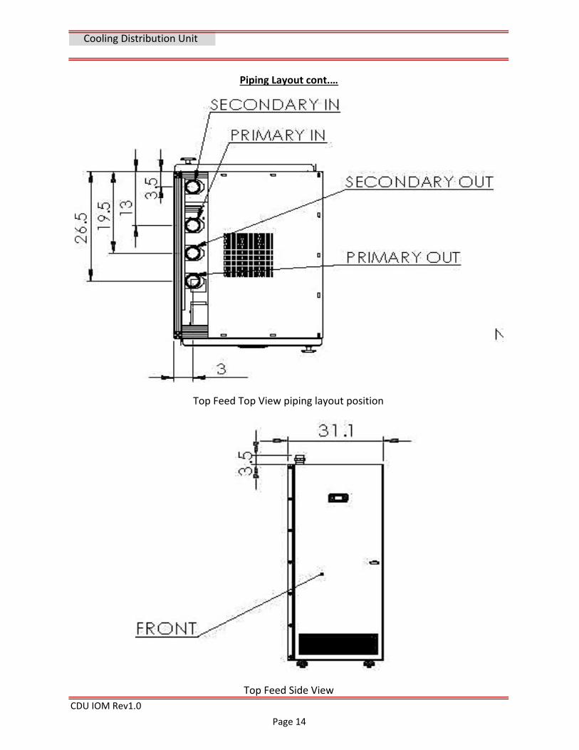
Piping Layout cont.…
Top Feed Top View piping layout position
Top Feed Side View
Cooling Distribution Unit
Page 14
CDU IOM Rev1.0
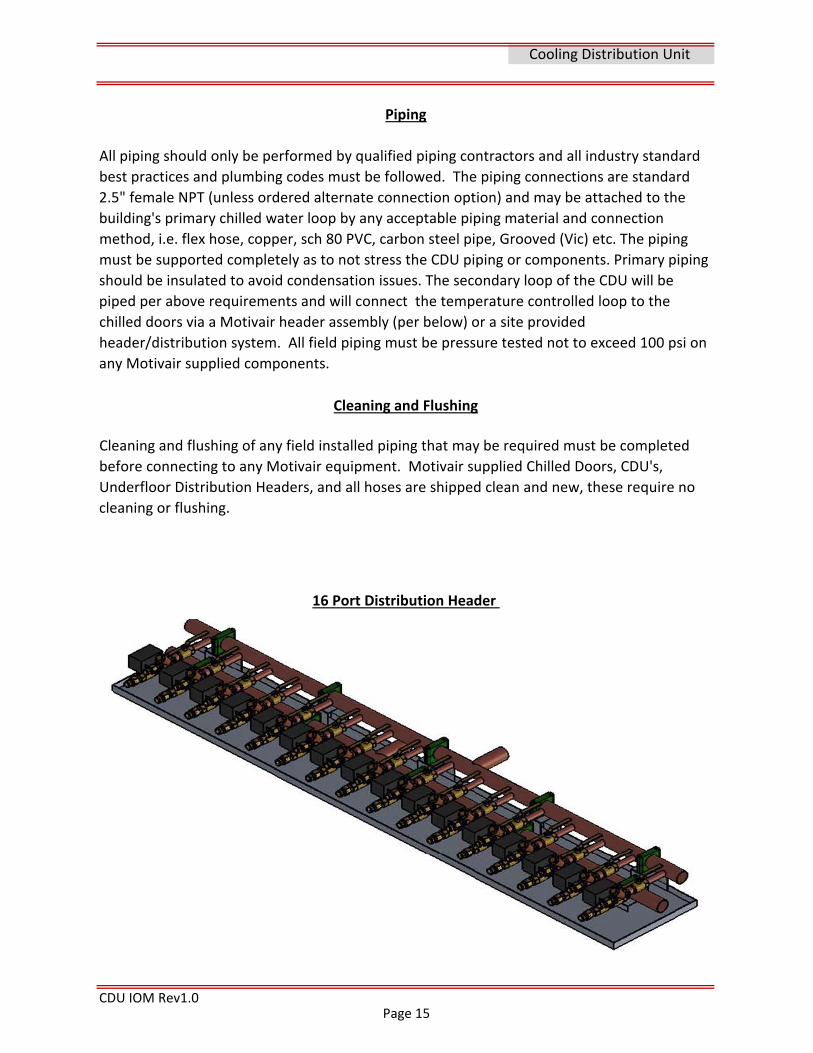
16 Port Distribution Header
All piping should only be performed by qualified piping contractors and all industry standard
best practices and plumbing codes must be followed. The piping connections are standard
2.5" female NPT (unless ordered alternate connection option) and may be attached to the
building's primary chilled water loop by any acceptable piping material and connection
method, i.e. flex hose, copper, sch 80 PVC, carbon steel pipe, Grooved (Vic) etc. The piping
must be supported completely as to not stress the CDU piping or components. Primary piping
should be insulated to avoid condensation issues. The secondary loop of the CDU will be
piped per above requirements and will connect the temperature controlled loop to the
chilled doors via a Motivair header assembly (per below) or a site provided
header/distribution system. All field piping must be pressure tested not to exceed 100 psi on
any Motivair supplied components.
Cleaning and Flushing
Cleaning and flushing of any field installed piping that may be required must be completed
before connecting to any Motivair equipment. Motivair supplied Chilled Doors, CDU's,
Underfloor Distribution Headers, and all hoses are shipped clean and new, these require no
cleaning or flushing.
Cooling Distribution Unit
Piping
Page 15
CDU IOM Rev1.0
To insure long term reliability and operation of the sealing components of the Motivair CDU
and coolant loop distribution components clean water with a low to no suspended solids level
is required for closed loop systems.
Suspended Particles can damage O‐rings, mechanical pump seals and cartridge valve seals
and operation. Excessive suspended solids will leave deposits in system piping, including
critical sealing and heat transfer surfaces. The following recommendations are a minimum for
and closed loop distribution system utilizing the Motivair Chilled door, CDU or header
distribution system.
Cooling Distribution Unit
Cleaning and Flushing
Good installation practice must include Initial system flushing
Cleaning and flushing of any field installed piping that may be required must be completed
before connecting to any Motivair equipment. Motivair supplied ChilledDoor®, CDU's,
Underfloor Distribution Headers, and all hoses are shipped clean and new, these require no
cleaning or flushing.
Minimum Water Quality Standard for Motivair Equipment
A water treatment professional should be consulted regarding the testing and proper
chemical treatment for a closed loop system’s composition and fluid requirements. Proper
levels of all loop and makeup water must be maintained per industry standards and best
practices. Proper levels of pH, Alkalinity, Chlorides, Nitrite, and Conductivity, along with other
chemicals and metals in the system must be tested for and monitored. A treatment program
should be implemented at the time of initial system commissioning to provide long term
system reliability. This testing is outside this documents scope.
Water testing and filtration must employed to ensure a system is filtered to <50 microns
(High limit of a closed loop system per industry standards) The recommendation by Motivair
is to utilize a 5 micron or less bag/cartage type filter in the closed loop or other suitable
method of removing suspended solids to a minimum 5 microns or less. Iron levels less than
<2.0 ppm ‐ Copper levels less than <0.1 ppm ‐ Suspended solids <1 mg/L.
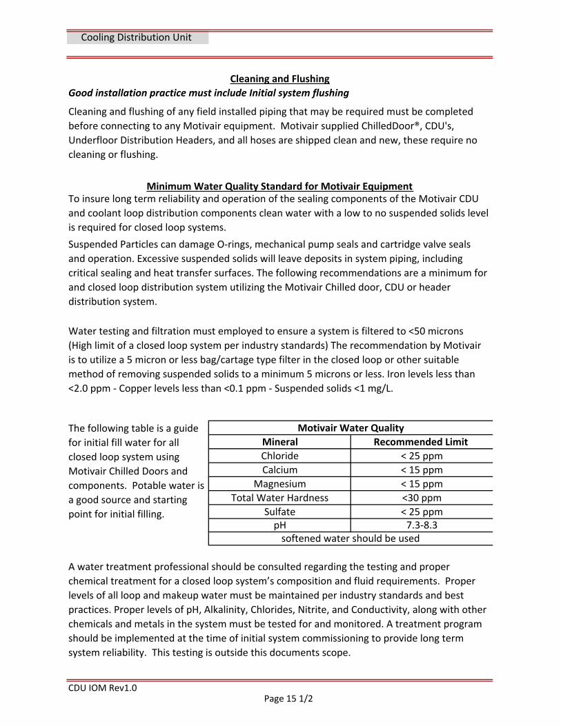
The following table is a guide
for initial fill water for all
closed loop system using
Motivair Chilled Doors and
components. Potable water is
a good source and starting
point for initial filling.
Motivair Water Quality
Mineral Recommended Limit
Chloride < 25 ppm
Calcium < 15 ppm
Magnesium < 15 ppm
Total Water Hardness <30 ppm
Sulfate < 25 ppmpH 7.3‐8.3softened water should be used
Page 15 1/2
CDU IOM Rev1.0
Water Quality cont…
The CDU Primary Loop should be supplied with clean, particulate free water or glycol. Note
that increased glycol concentrations reduce CDU efficiency and cooling capacity. It is the
responsibility of the owner to ensure that the Primary Loop supply has less than 500 microns
of particulate.
TIP: The flow path for purging air is from the fill in CDU pump return pipe through the pump
and exchanger to the header supply and zone valves through the chilled door coil and back to
the header check valve inlet. Removing the quick connect hose at the header check valve and
purging into a suitable container will force the air out at the low point. Final purging is done
at the chilled door coil air vents and CDU auto vents.
The CDU Secondary Loop should be filled with clean, particulate‐free, softened water with
suitable corrosion inhibitors and biocides. Consult a water treatment service provider if you
need assistance.
Cooling Distribution Unit
The secondary loop should be filled slowly using a hose and transfer pump or suitable
municipal water supply at the drain and fill valve located on the suction inlet piping of the
CDU pumps. The Bottom feed CDU has auto vents at the high points to purge the air from
both the primary and secondary water loops. The auto vents are to be open during filling,
venting, and start‐up. The auto vent manual isolation valves should be closed following the
completion of the commissioning process. Top feed CDUs may be filled in the same manner,
but air venting and purging must be provided at the highest point of elevation in the building
piping system.
A CDU connected to a Motivair under floor distribution header and to Chilled Doors will
require venting at both the CDU per above and at the chilled door coil vent ports. (refer to
the Chilled Door Manual for installation and venting information). The under floor
distribution header contains manual isolation valves, actuator valves, and one way check
valves. These valves/circuits should be open and purged one at a time to ensure all air is
removed.
Fill & Vent Note: The flow path is stopped at the check valves on the header.
Filling and Venting
Warning: Do not use deionized water (DIW) in chilled door closed loop systems as
DIW is corrosive to certain metals.
The use of Propylene and Ethylene glycol mixtures and water treatment additives that are
compatible with the piping and wetted materials used in the coolant distribution system are
acceptable. A qualified water treatment contractor should be consulted for
recommendations and water analysis testing that meet your specific requirements.
Page 16
Section 5
CDU IOM Rev1.0
COMMISSIONING
Cooling Distribution Unit
7. Check secondary loop pressure gauges on CDU have a minimum pressure to start.
components, controls, valves, pipes, vents, auto bleeders and heat exchangers before beginning commissioning. Safety is no accident.
Commissioning
Pre‐commissioning checks
1. Visual inspection of unit to confirm all components and panels are in place.
2. Check all water piping to CDU and system are properly supported and insulated
3. Check primary loop water supply is open and within pressure limit of CDU.
4. Check all electrical connection's tightness and proper routing.
5. Check site electrical supply power matches nameplate voltage on CDU 6. Confirm the fuse or circuit breaker and wire size are correct for the unit
The CDU will alarm on low pressure below 5 psi operating pressure after 90 seconds 8. "Know the system". Take another look at the complete hydronic loop and all
2. Apply power to the CDU by closing the A/B disconnects on the front panel. The HMI
display will be visible in about 30 seconds and will display the main screen showing pump
pressures and "Off by Keyboard" message.
3. Check the display screen and note the pump supply and return static pressures. The initial
static charge should be between 15 ‐ 30 psi. Do not operate pumps "dry".
4. Navigate the PLC to command the unit “ON” via the user interface. (See controls section
for description and navigation of screens). Open the front door of the CDU and locate the
operating pump and check that rotation matches the directional arrow on pump. The CDU's
are factory wired and phased ABC for proper rotation. If rotation is reversed, stop unit, open
disconnects and correct phasing.
5. The Pumps will operate at a speed to maintain a differential pressure as per set point
(default = 25 psi). The auto vent air bleeders should remain open to remove any entrained
air in the system. The minimum pump return pressure operating at 60 hz is 10 psi. Add fluid
as necessary to maintain pressure.
1. If Motivair or one of its agents was not contracted for commissioning assistance, please
notify Motivair before commencing start up
6. Navigate to pump rotation screen, switch lead pump and continue above checks.
7. Navigate to the Temperature I/O screen and note the Primary and secondary loop temps.
The HXP In temp should be below 60°F and the HXS Out temp should be at set point (default
= 65°F). The "Main Outputs" screen will display the signal (0‐10v) output to the temperature
control actuator valve and the pump VFD. Check all HX temperatures are reading as
expected.
Page 17
Section 6
CDU IOM Rev1.0
1. The PLC set to "ON" and sensing the leaving secondary loop temperature, sends a 0‐10 volt
output signal to the motorized actuator valve on the inlet building supply. The valve
modulates to maintain secondary loop temperature to the Chilled Doors at set point.
2. The PLC set to "ON" and monitoring the lead pump supply and return pressure differential
sends a 0‐10 volt output signal to the VFD to maintain secondary loop flow volume at set
point per the current system demand.
3. Secondary loop pump pressures and outlet temperature are displayed on the HMI home
screen.
4. Entering & leaving primary & secondary loop temperatures are displayed on the
Temperature I/O screen.
5. Chilled doors (CDU heat load) are fitted with their own load‐based modulating control
valves. Therefore secondary pump pressure will vary based on the number of Chilled Doors
in service and/or the actual heat load applied to the Chilled Doors. Secondary pump pressure
is monitored by a pressure transducer in the pump discharge header and constant design
pump pressure is maintained by the VFD connected to the operating pump.
6. Triple duty valves on the discharge of each pump provide:
A. Final adjustment of operating pump head pressure, if needed, to balance pumps on full
load to design head pressure.
B. Check valve to prevent backflow for automatic pump changeover.
C. Isolation of pump for removal.
Description/Sequence of Operation
Commissioning Cont.
8. Following a suitable period of time to be sure all air has been removed from the closed
loops, close the auto vent safety caps and valves to prevent accidental leaks.
10. Record all measurements and readings and complete the "Start up Report" located in
the documents section of this manual.
9. The Optional leak detection system sensor should be located in the lowest appropriate
area (floor level or under floor) to detect moisture present. Make sure water detection LED
(green) is lit on WDS module, test alarm with water on sensor.
Cooling Distribution Unit
OPERATION
Page 18
CDU IOM Rev1.0
Description/Sequence of Operation cont.
7. Closed diaphragm expansion tank allows for hydraulic expansion of water in closed loop
during temperature changes that may occur between filling time, operation and shut‐down.
8. The relative humidity sensor monitors data center humidity to ensure secondary water
loop temperature remains above the dew point. This is necessary to prevent condensation
on the coils inside the Chilled doors. In the event the data center humidity reaches a dew
point within 3°F of the leaving secondary water loop temperature, the dew point warning is
activated and the PLC throttles the primary water control valve to reduce the cooling effect
on the secondary loop. The CDU will automatically adjust outlet secondary water
temperature to stay 3°F above room dew point.
9. Check communication of all selected PLC points to master control or BMS via BacNet, LON
or Modbus.
10. CDU is set‐up to accept A/B power supply check/test switch over (if option is connected)
by opening A disconnect switch.
Cooling Distribution Unit
Page 19
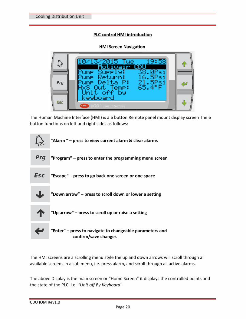
“Alarm “ – press to view current alarm & clear alarms
“Program” – press to enter the programming menu screen
“Escape” – press to go back one screen or one space
“Down arrow” – press to scroll down or lower a setting
“Up arrow” – press to scroll up or raise a setting
CDU IOM Rev1.0
The above Display is the main screen or “Home Screen” it displays the controlled points and
the state of the PLC i.e. "Unit off By Keyboard"
HMI Screen Navigation
The Human Machine Interface (HMI) is a 6 button Remote panel mount display screen The 6
button functions on left and right sides as follows:
The HMI screens are a scrolling menu style the up and down arrows will scroll through all
available screens in a sub menu, i.e. press alarm, and scroll through all active alarms.
“Enter” – press to navigate to changeable parameters and confirm/save changes
PLC control HMI introduction
Cooling Distribution Unit
Page 20
CDU IOM Rev1.0
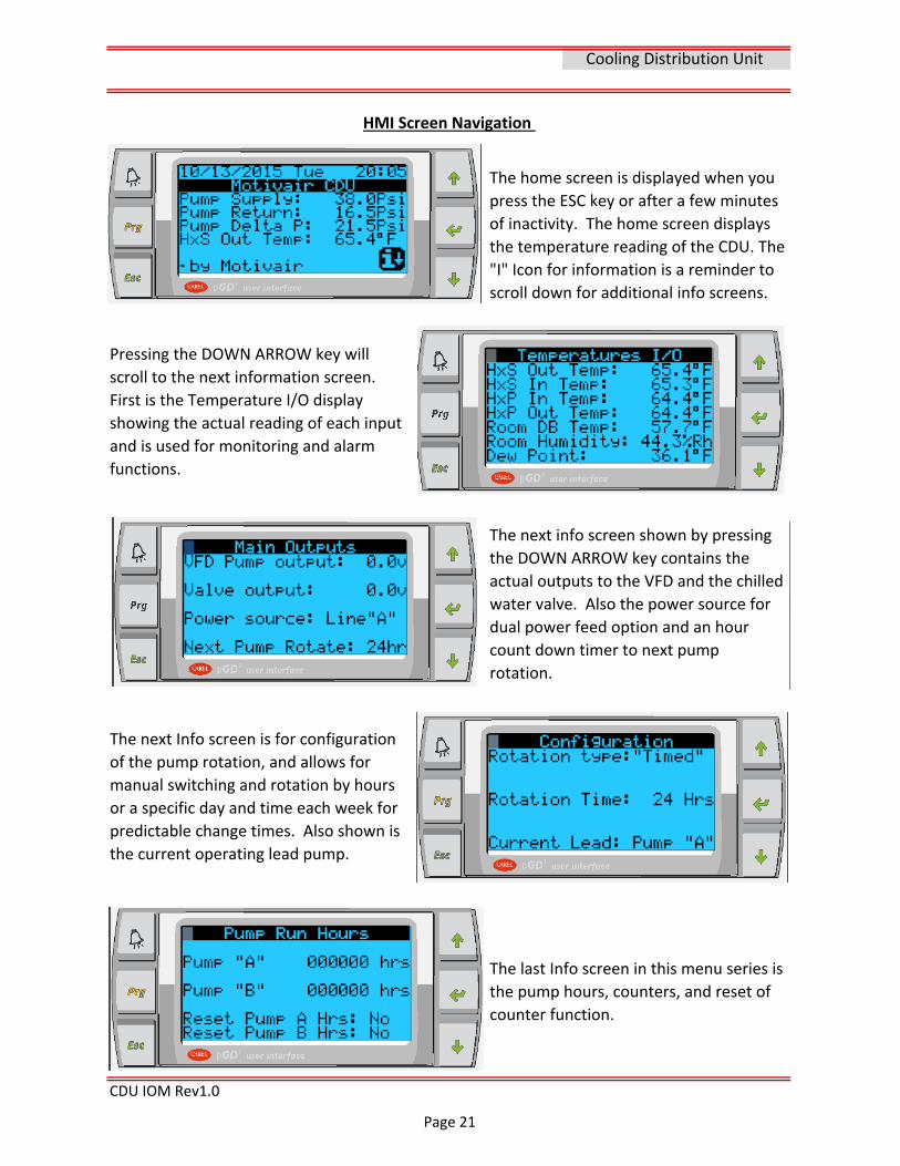
HMI Screen Navigation
The home screen is displayed when you
press the ESC key or after a few minutes
of inactivity. The home screen displays
the temperature reading of the CDU. The
"I" Icon for information is a reminder to
scroll down for additional info screens.
Pressing the DOWN ARROW key will
scroll to the next information screen.
First is the Temperature I/O display
showing the actual reading of each input
and is used for monitoring and alarm
functions.
The next info screen shown by pressing
the DOWN ARROW key contains the
actual outputs to the VFD and the chilled
water valve. Also the power source for
dual power feed option and an hour
count down timer to next pump
rotation.
The next Info screen is for configuration
of the pump rotation, and allows for
manual switching and rotation by hours
or a specific day and time each week for
predictable change times. Also shown is
the current operating lead pump.
The last Info screen in this menu series is
the pump hours, counters, and reset of
counter function.
Cooling Distribution Unit
Page 21
CDU IOM Rev1.0
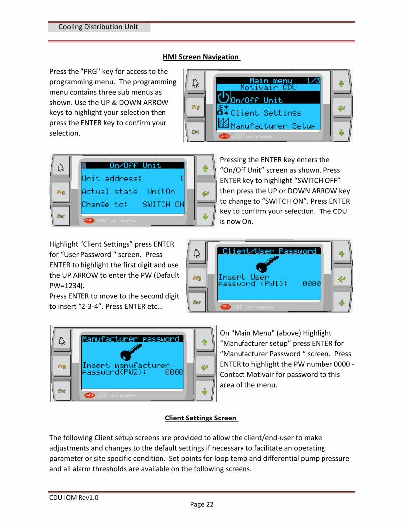
Highlight “Client Settings” press ENTER
for “User Password “ screen. Press
ENTER to highlight the first digit and use
the UP ARROW to enter the PW (Default
PW=1234).
Press ENTER to move to the second digit
to insert “2‐3‐4”. Press ENTER etc…
HMI Screen Navigation
Press the "PRG" key for access to the
programming menu. The programming
menu contains three sub menus as
shown. Use the UP & DOWN ARROW
keys to highlight your selection then
press the ENTER key to confirm your
selection.
Pressing the ENTER key enters the
“On/Off Unit” screen as shown. Press
ENTER key to highlight “SWITCH OFF”
then press the UP or DOWN ARROW key
to change to “SWITCH ON”. Press ENTER
key to confirm your selection. The CDU
is now On.
On "Main Menu" (above) Highlight
“Manufacturer setup” press ENTER for
“Manufacturer Password “ screen. Press
ENTER to highlight the PW number 0000 ‐
Contact Motivair for password to this
area of the menu.
Cooling Distribution Unit
Client Settings Screen
The following Client setup screens are provided to allow the client/end‐user to make
adjustments and changes to the default settings if necessary to facilitate an operating
parameter or site specific condition. Set points for loop temp and differential pump pressure
and all alarm thresholds are available on the following screens.
Page 22
CDU IOM Rev1.0
Cooling Distribution Unit
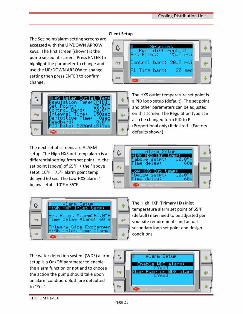
Client Setup The Set‐point/alarm setting screens are
accessed with the UP/DOWN ARROW
keys. The first screen (shown) is the
pump set‐point screen. Press ENTER to
highlight the parameter to change and
use the UP/DOWN ARROW to change
setting then press ENTER to confirm
change.
The HXS outlet temperature set point is
a PID loop setup (default). The set point
and other parameters can be adjusted
on this screen. The Regulation type can
also be changed form PID to P
(Proportional only) if desired. (Factory
defaults shown)
The next set of screens are ALARM
setup. The High HXS out temp alarm is a
differential setting from set point i.e. the
set point (above) of 65°F + the ° above
setpt 10°F = 75°F alarm point temp
delayed 60 sec. The Low HXS alarm °
below setpt ‐ 10°F = 55°F
The High HXP (Primary HX) Inlet
temperature alarm set point of 65°F
(default) may need to be adjusted per
your site requirements and actual
secondary loop set point and design
conditions.
The water detection system (WDS) alarm
setup is a On/Off parameter to enable
the alarm function or not and to choose
the action the pump should take upon
an alarm condition. Both are defaulted
to "Yes".
Page 23
CDU IOM Rev1.0
Cooling Distribution Unit
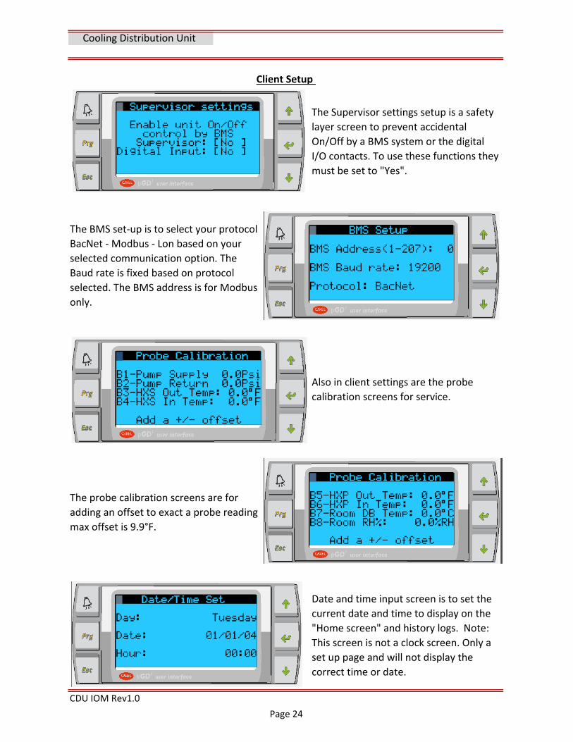
Client Setup
The Supervisor settings setup is a safety
layer screen to prevent accidental
On/Off by a BMS system or the digital
I/O contacts. To use these functions they
must be set to "Yes".
The BMS set‐up is to select your protocol
BacNet ‐ Modbus ‐ Lon based on your
selected communication option. The
Baud rate is fixed based on protocol
selected. The BMS address is for Modbus
only.
Also in client settings are the probe
calibration screens for service.
The probe calibration screens are for
adding an offset to exact a probe reading
max offset is 9.9°F.
Date and time input screen is to set the
current date and time to display on the
"Home screen" and history logs. Note:
This screen is not a clock screen. Only a
set up page and will not display the
correct time or date.
Page 24
CDU IOM Rev1.0
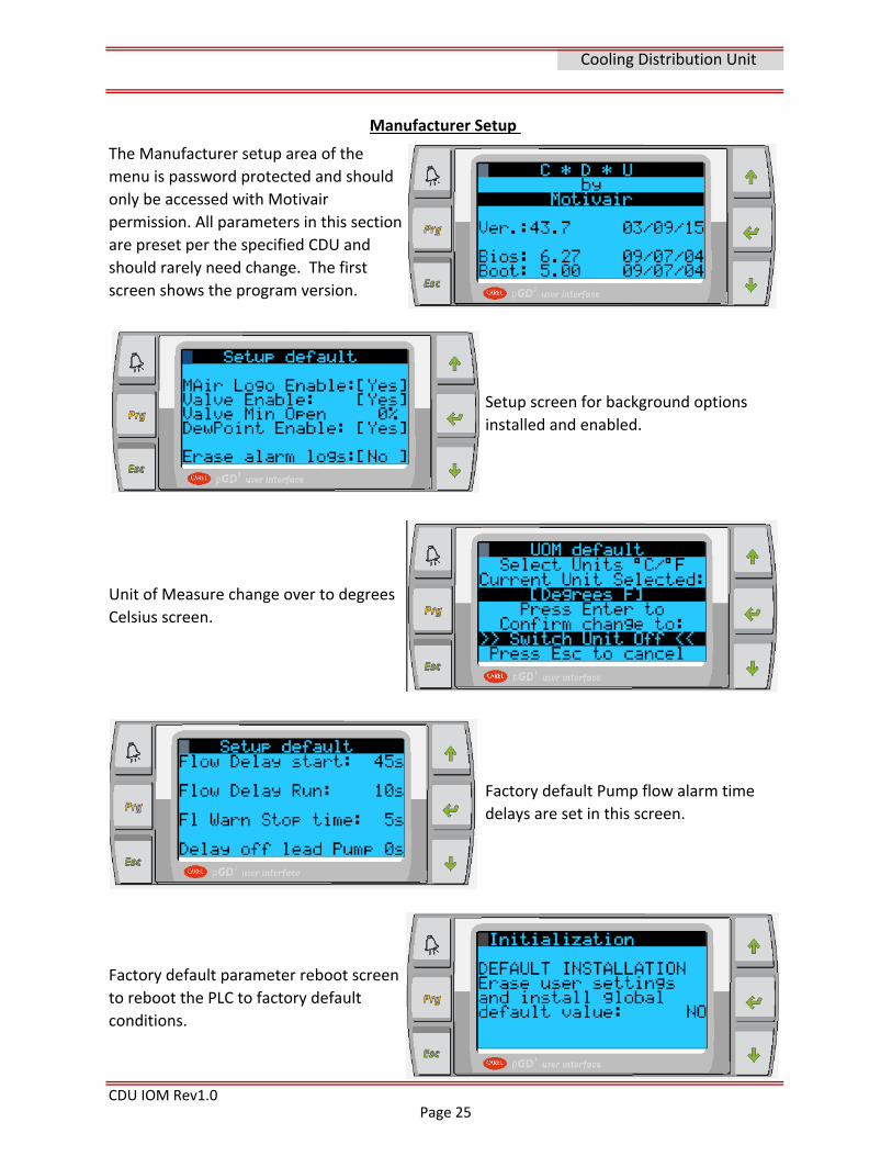
The Manufacturer setup area of the
menu is password protected and should
only be accessed with Motivair
permission. All parameters in this section
are preset per the specified CDU and
should rarely need change. The first
screen shows the program version.
Setup screen for background options
installed and enabled.
Cooling Distribution Unit
Manufacturer Setup
Unit of Measure change over to degrees
Celsius screen.
Factory default Pump flow alarm time
delays are set in this screen.
Factory default parameter reboot screen
to reboot the PLC to factory default
conditions.
Page 25
CDU IOM Rev1.0
Cooling Distribution Unit
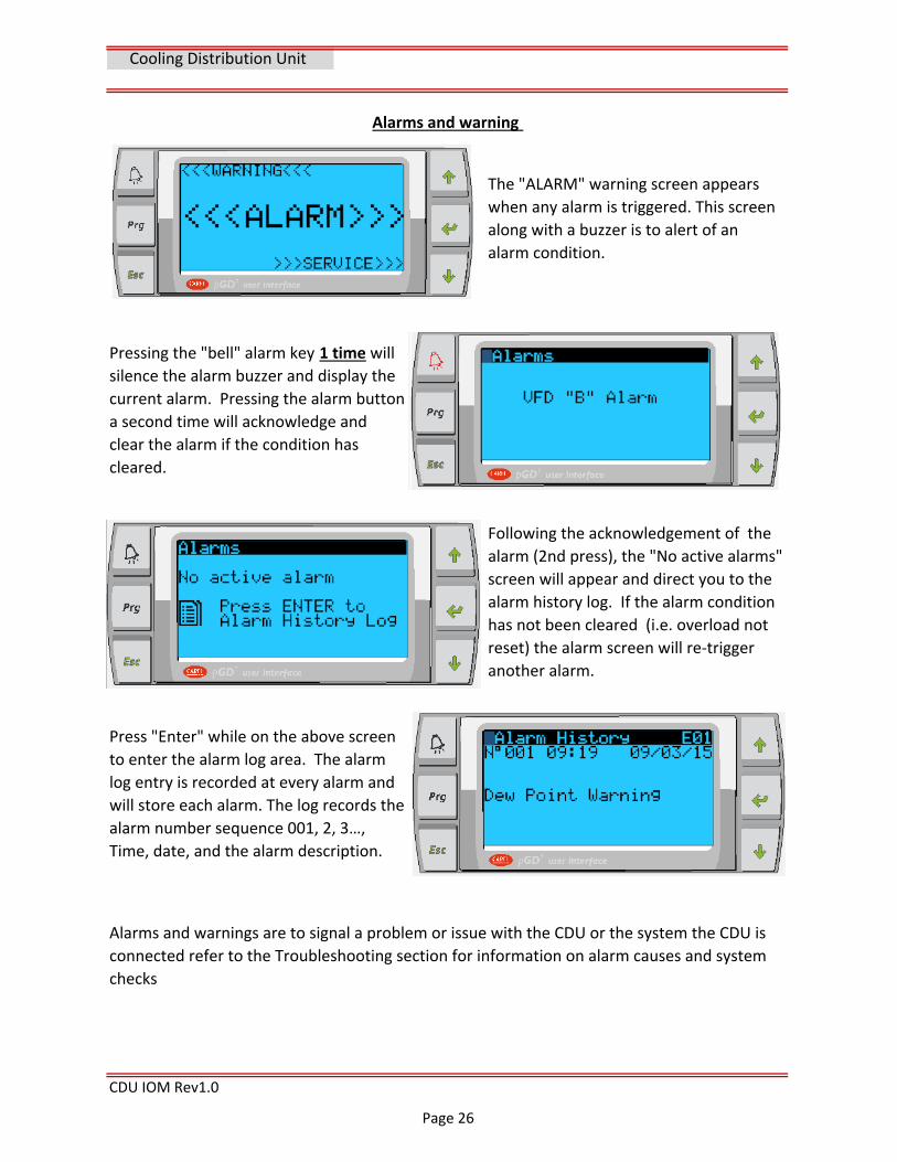
Alarms and warning
The "ALARM" warning screen appears
when any alarm is triggered. This screen
along with a buzzer is to alert of an
alarm condition.
Pressing the "bell" alarm key 1 time will
silence the alarm buzzer and display the
current alarm. Pressing the alarm button
a second time will acknowledge and
clear the alarm if the condition has
cleared.
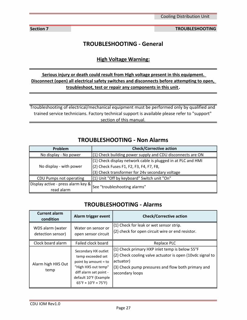
Following the acknowledgement of the
alarm (2nd press), the "No active alarms"
screen will appear and direct you to the
alarm history log. If the alarm condition
has not been cleared (i.e. overload not
reset) the alarm screen will re‐trigger
another alarm.
Press "Enter" while on the above screen
to enter the alarm log area. The alarm
log entry is recorded at every alarm and
will store each alarm. The log records the
alarm number sequence 001, 2, 3…,
Time, date, and the alarm description.
Alarms and warnings are to signal a problem or issue with the CDU or the system the CDU is
connected refer to the Troubleshooting section for information on alarm causes and system
checks
Page 26
Section 7
CDU IOM Rev1.0
Display active ‐ press alarm key &
read alarmSee "troubleshooting alarms"
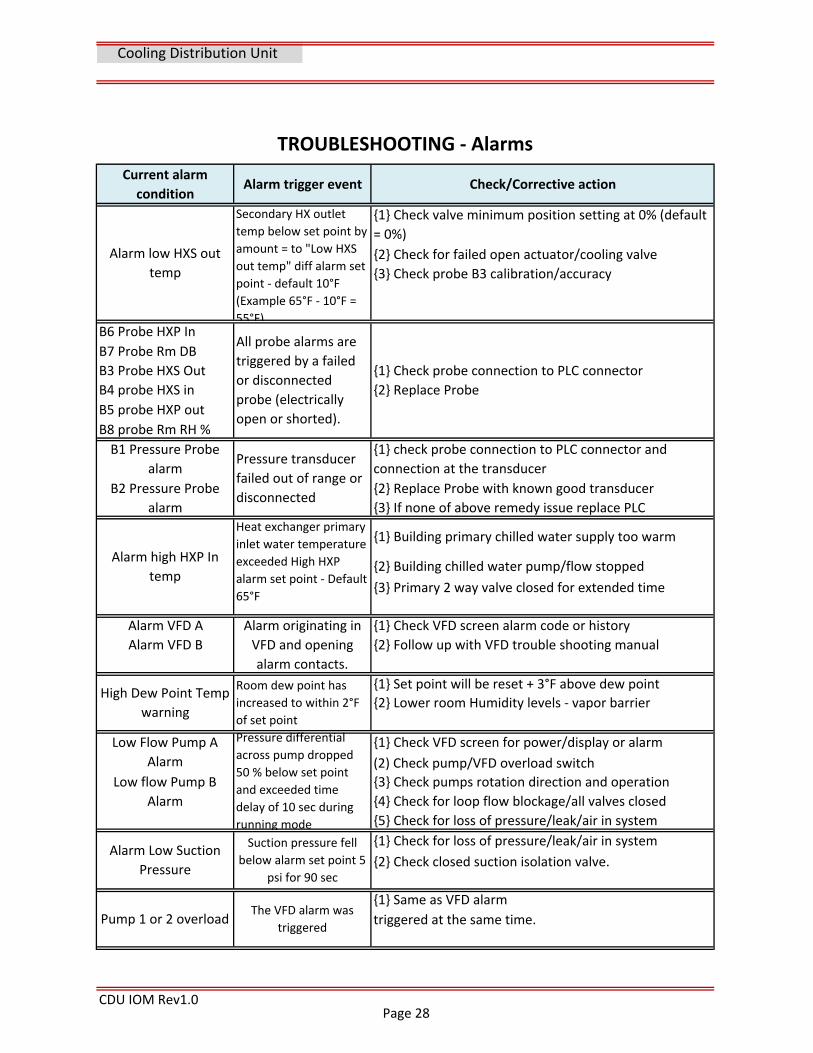
Alarm high HXS Out
temp
Secondary HX outlet
temp exceeded set
point by amount = to
"High HXS out temp"
diff alarm set point ‐
default 10°F (Example
65°F + 10°F = 75°F)
{3} Check pump pressures and flow both primary and
secondary loops
TROUBLESHOOTING
No display ‐ No power
TROUBLESHOOTING ‐ Alarms
Current alarm
conditionAlarm trigger event Check/Corrective action
WDS alarm (water
detection sensor)
Water on sensor or
open sensor circuit
{1} Check for leak or wet sensor strip.
{2} check for open circuit wire or end resistor.
Clock board alarm Failed clock board
{1} Check building power supply and CDU disconnects are ON
No display ‐ with power
{1} Check display network cable is plugged in at PLC and HMI
{2} Check Fuses F1, F2, F3, F4, F7, F8,
{3} Check transformer for 24v secondary voltage
Check/Corrective action
CDU Pumps not operating {1} Unit "Off by keyboard" Switch unit "On"
Cooling Distribution Unit
TROUBLESHOOTING ‐ General
High Voltage Warning:
Serious injury or death could result from High voltage present in this equipment.
Disconnect (open) all electrical safety switches and disconnects before attempting to open,
troubleshoot, test or repair any components in this unit .
Troubleshooting of electrical/mechanical equipment must be performed only by qualified and
trained service technicians. Factory technical support is available please refer to "support"
section of this manual.
TROUBLESHOOTING ‐ Non Alarms
Problem
Replace PLC
{1} Check primary HXP inlet temp is below 55°F
{2} Check cooling valve actuator is open (10vdc signal to
actuator)
Page 27
{2} Building chilled water pump/flow stopped
{3} Primary 2 way valve closed for extended time
CDU IOM Rev1.0
Alarm high HXP In
temp
Heat exchanger primary
inlet water temperature
exceeded High HXP
alarm set point ‐ Default
65°F
Alarm VFD A Alarm originating in
VFD and opening
alarm contacts.
{1} Check VFD screen alarm code or history
Alarm VFD B
{3} Check probe B3 calibration/accuracy
Alarm low HXS out
temp
Secondary HX outlet
temp below set point by
amount = to "Low HXS
out temp" diff alarm set
point ‐ default 10°F
(Example 65°F ‐ 10°F =
55°F)
Pump 1 or 2 overload The VFD alarm was
triggered
{1} Same as VFD alarm
triggered at the same time.
{2} Check for failed open actuator/cooling valve
B6 Probe HXP InAll probe alarms are
triggered by a failed
or disconnected
probe (electrically
open or shorted).
B7 Probe Rm DB
B3 Probe HXS Out {1} Check probe connection to PLC connector
B4 probe HXS in
{2} Follow up with VFD trouble shooting manual
Cooling Distribution Unit
Pressure differential
across pump dropped
50 % below set point
and exceeded time
delay of 10 sec during
running mode
{1} Check VFD screen for power/display or alarm
Low flow Pump B
Alarm
{1} Check valve minimum position setting at 0% (default
= 0%)
{3} If none of above remedy issue replace PLC
{1} Check for loss of pressure/leak/air in system Alarm Low Suction
Pressure
Suction pressure fell
below alarm set point 5
psi for 90 sec {2} Check closed suction isolation valve.
(2) Check pump/VFD overload switch
{3} Check pumps rotation direction and operation
{4} Check for loop flow blockage/all valves closed
{5} Check for loss of pressure/leak/air in system
High Dew Point Temp
warning
{1} Building primary chilled water supply too warm
Current alarm
conditionAlarm trigger event
TROUBLESHOOTING ‐ Alarms
Check/Corrective action
Room dew point has
increased to within 2°F
of set point
{1} Set point will be reset + 3°F above dew point
{2} Lower room Humidity levels ‐ vapor barrier
Low Flow Pump A
Alarm
{2} Replace Probe
B5 probe HXP out
B8 probe Rm RH %
B1 Pressure Probe
alarmPressure transducer
failed out of range or
disconnected
{1} check probe connection to PLC connector and
connection at the transducer
B2 Pressure Probe
alarm
{2} Replace Probe with known good transducer
Page 28
Section 8
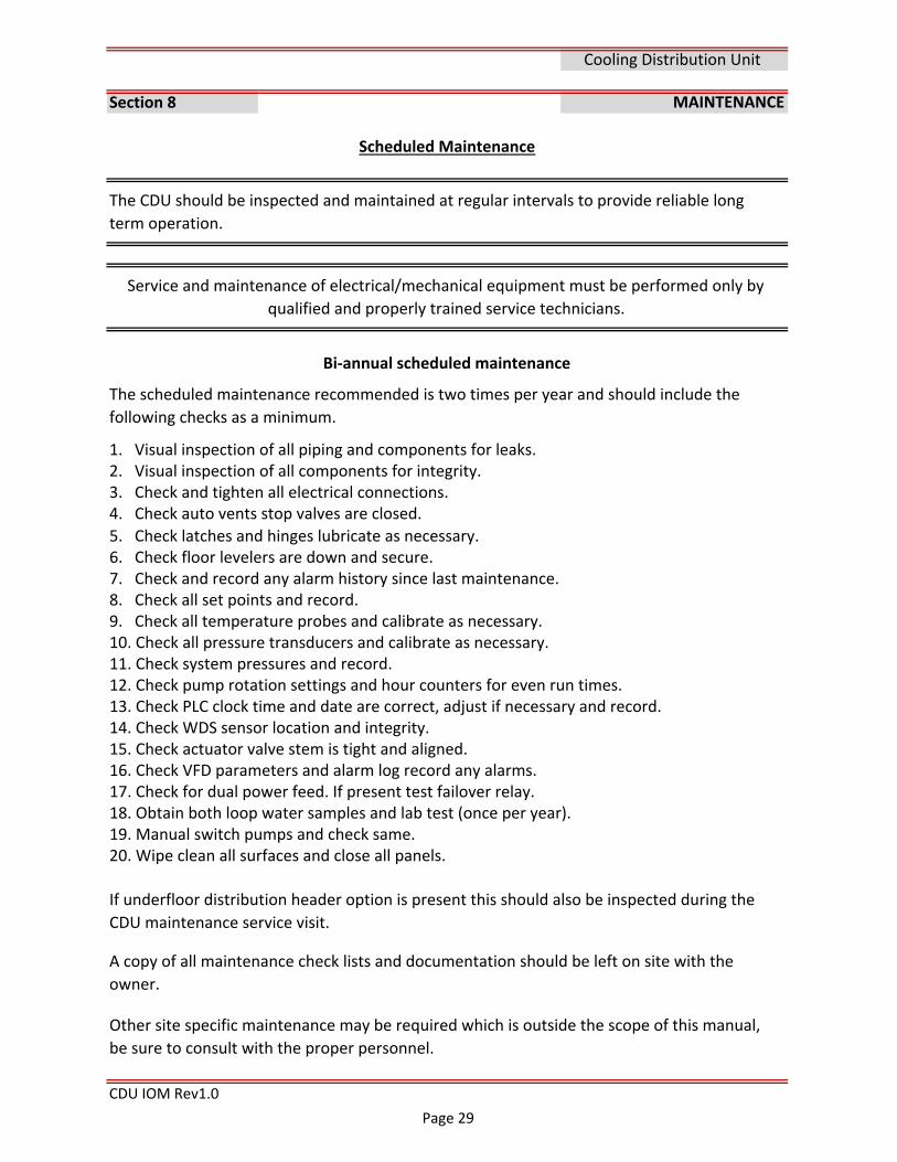
1. Visual inspection of all piping and components for leaks.2. Visual inspection of all components for integrity. 3. Check and tighten all electrical connections.4. Check auto vents stop valves are closed.
5. Check latches and hinges lubricate as necessary.6. Check floor levelers are down and secure.7. Check and record any alarm history since last maintenance.8. Check all set points and record.9. Check all temperature probes and calibrate as necessary.10. Check all pressure transducers and calibrate as necessary.11. Check system pressures and record.12. Check pump rotation settings and hour counters for even run times.13. Check PLC clock time and date are correct, adjust if necessary and record.14. Check WDS sensor location and integrity.15. Check actuator valve stem is tight and aligned.16. Check VFD parameters and alarm log record any alarms. 17. Check for dual power feed. If present test failover relay. 18. Obtain both loop water samples and lab test (once per year).19. Manual switch pumps and check same.20. Wipe clean all surfaces and close all panels.
CDU IOM Rev1.0
MAINTENANCE
If underfloor distribution header option is present this should also be inspected during the
CDU maintenance service visit.
A copy of all maintenance check lists and documentation should be left on site with the
owner.
Other site specific maintenance may be required which is outside the scope of this manual,
be sure to consult with the proper personnel.
Cooling Distribution Unit
Bi‐annual scheduled maintenance
The scheduled maintenance recommended is two times per year and should include the
following checks as a minimum.
Scheduled Maintenance
The CDU should be inspected and maintained at regular intervals to provide reliable long
term operation.
Service and maintenance of electrical/mechanical equipment must be performed only by
qualified and properly trained service technicians.
Page 29
Section 9
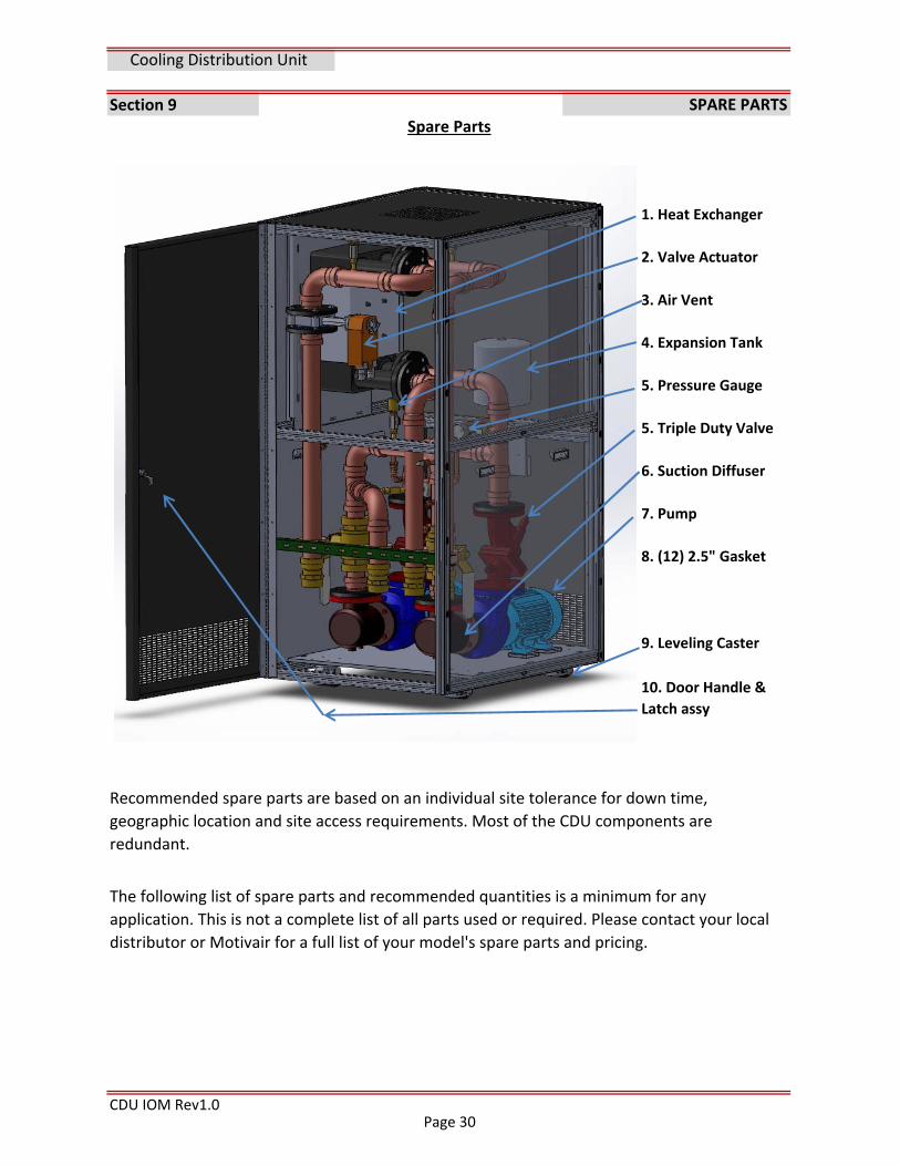
2. Valve Actuator
3. Air Vent
4. Expansion Tank
5. Pressure Gauge
5. Triple Duty Valve
6. Suction Diffuser
7. Pump
8. (12) 2.5" Gasket
9. Leveling Caster
CDU IOM Rev1.0
SPARE PARTS
Cooling Distribution Unit
10. Door Handle &
Latch assy
Recommended spare parts are based on an individual site tolerance for down time,
geographic location and site access requirements. Most of the CDU components are
redundant.
The following list of spare parts and recommended quantities is a minimum for any
application. This is not a complete list of all parts used or required. Please contact your local
distributor or Motivair for a full list of your model's spare parts and pricing.
Spare Parts
1. Heat Exchanger
Page 30
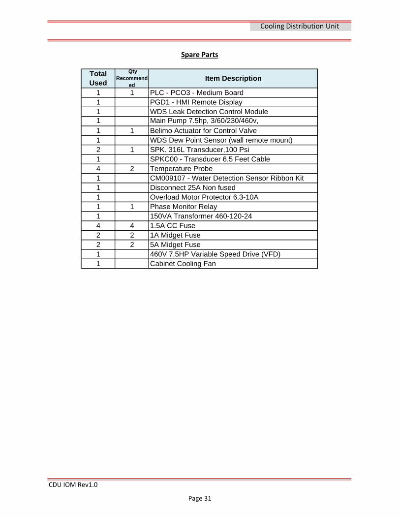
1 1 PLC - PCO3 - Medium Board1 PGD1 - HMI Remote Display1 WDS Leak Detection Control Module1 Main Pump 7.5hp, 3/60/230/460v,1 1 Belimo Actuator for Control Valve1 WDS Dew Point Sensor (wall remote mount)2 1 SPK. 316L Transducer,100 Psi1 SPKC00 - Transducer 6.5 Feet Cable4 2 Temperature Probe1 CM009107 - Water Detection Sensor Ribbon Kit1 Disconnect 25A Non fused1 Overload Motor Protector 6.3-10A1 1 Phase Monitor Relay1 150VA Transformer 460-120-244 4 1.5A CC Fuse2 2 1A Midget Fuse2 2 5A Midget Fuse1 460V 7.5HP Variable Speed Drive (VFD)1 Cabinet Cooling Fan
CDU IOM Rev1.0
Item DescriptionTotal Used
Qty Recommend
ed
Cooling Distribution Unit
Spare Parts
Page 31
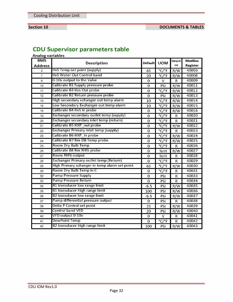
Section 10
CDU IOM Rev1.0
Cooling Distribution Unit
DOCUMENTS & TABLES
Page 32
CDU IOM Rev1.0
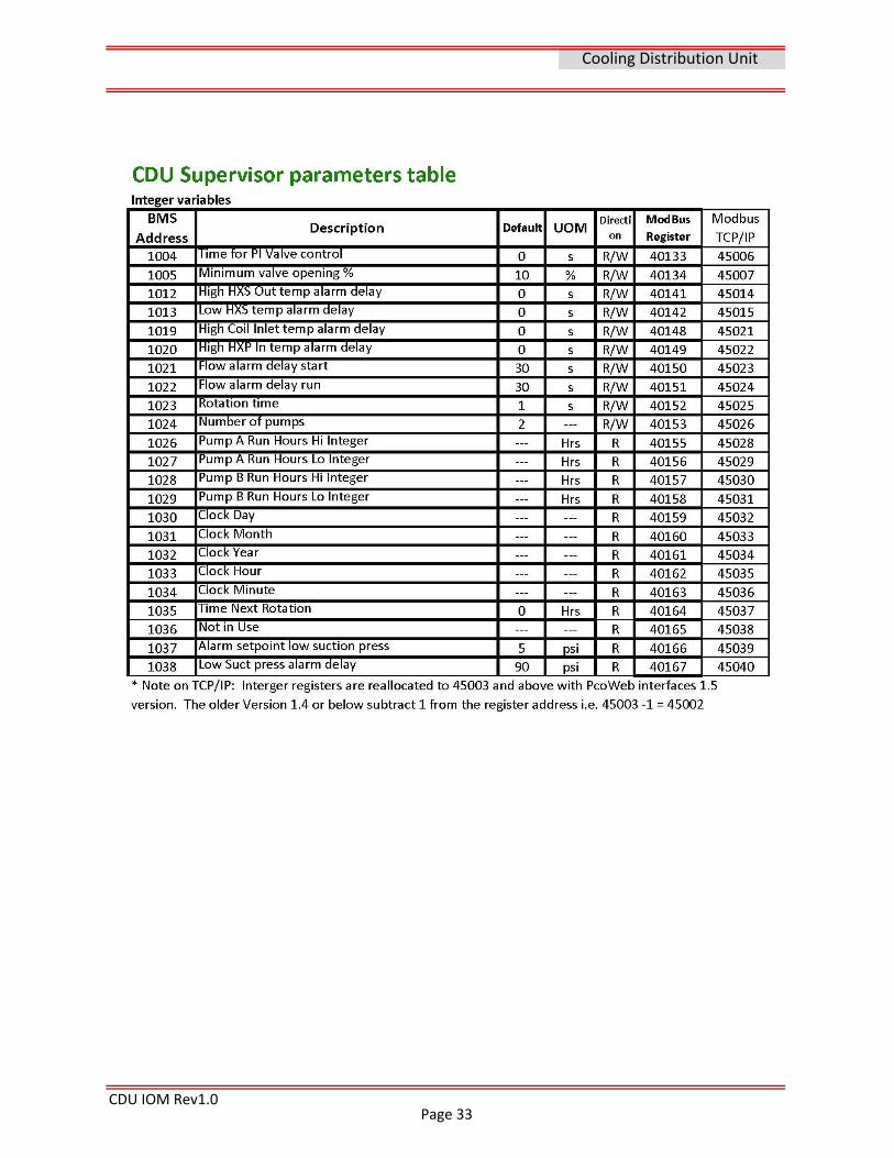
Cooling Distribution Unit
Page 33
CDU IOM Rev1.0
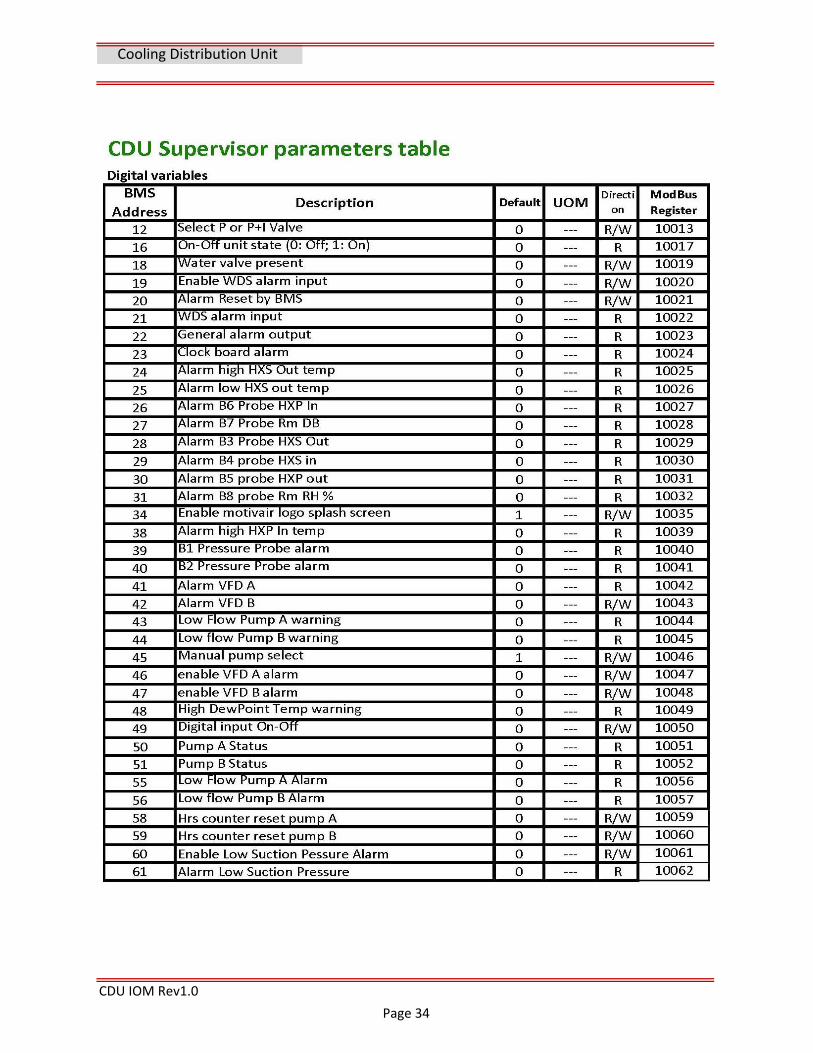
Cooling Distribution Unit
Page 34
CDU IOM Rev1.0
Cooling Distribution Unit
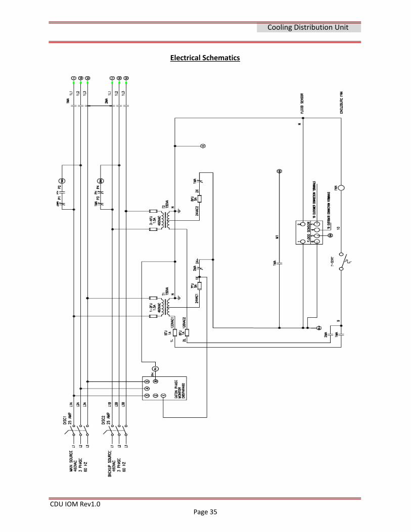
Electrical Schematics
Page 35
CDU IOM Rev1.0
Cooling Distribution Unit
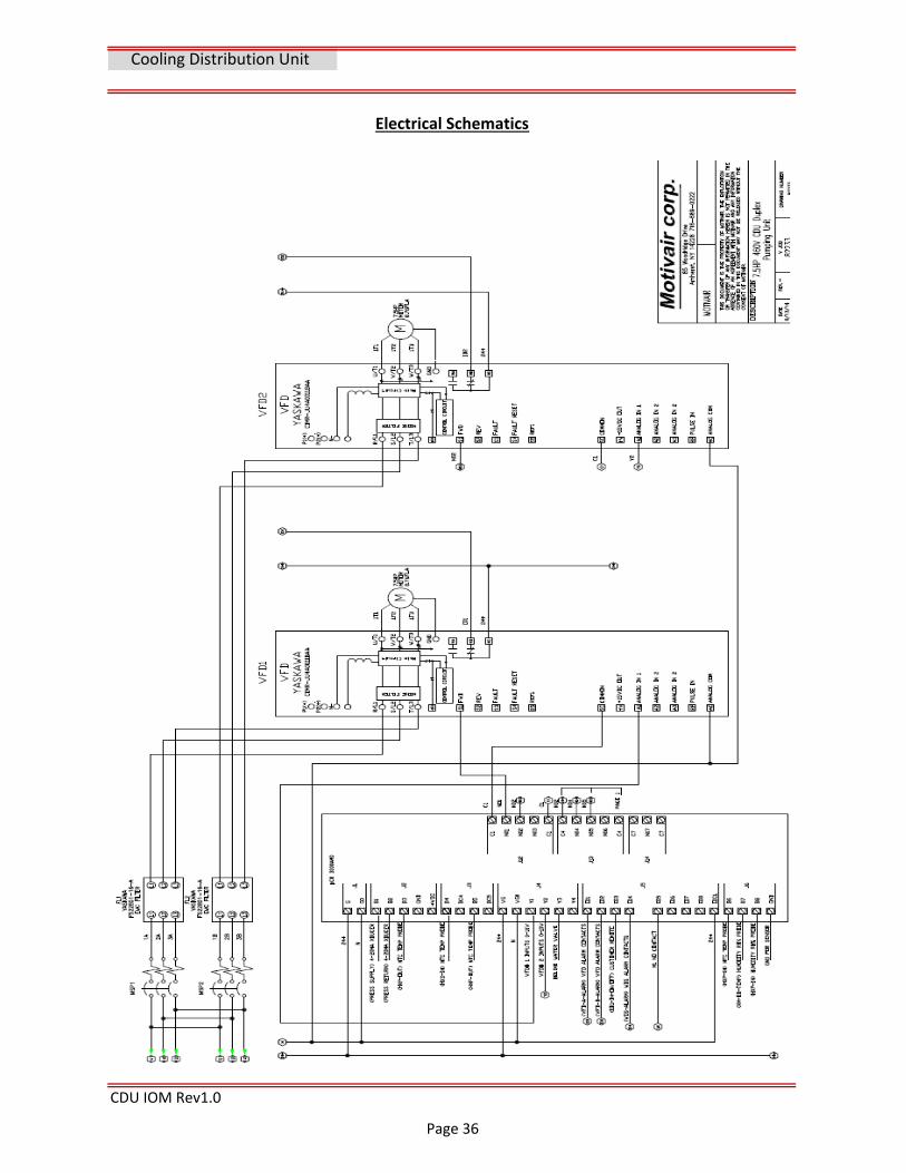
Electrical Schematics
Page 36
CDU IOM Rev1.0
Cooling Distribution Unit
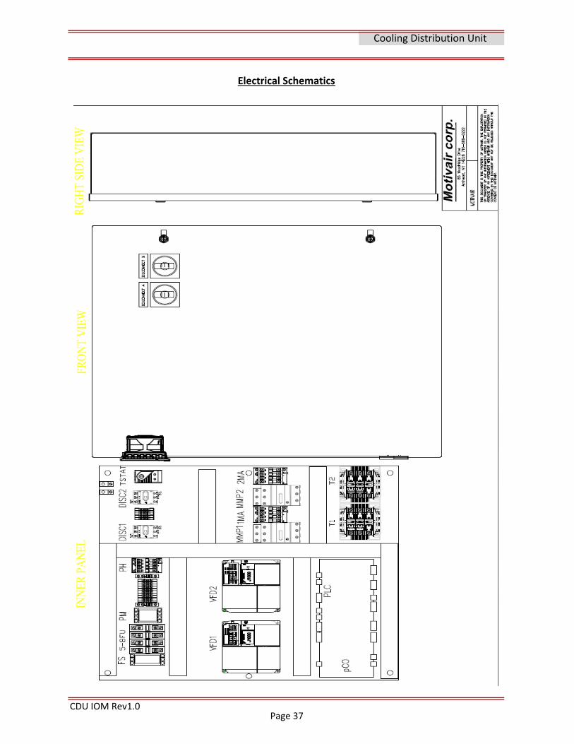
Electrical Schematics
Page 37
Section 11
CDU IOM Rev1.0
Cooling Distribution Unit
SUPPORT & WARRANTY
Support <> Contact <> Warranty Information
Factory Service & Support:
www.motivaircorp.com
Additional information on this product may be found at
www.chilleddoor.com
Motivair Corporation
85 Woodridge Drive
Amherst, New York, 14228
716‐691‐9222 Phone
716‐691‐9229 Fax
Parts <> Service <> Technical support Email
www.motivaircorp.supportsystem.com also available through our web site link at
www.motivaircorp.com/service‐support
https://motivaircorp.supportsystem.com/account.php?do=create to create an account.
Once an account is created you can create support tickets from your email account using
A service support portal is available at the following link
Visit the Motivair service portal at
WARRANTY: This product carries a 1‐year Parts Only Warranty. A copy of this warranty is
shipped with your Cooling Distribution Unit. An additional copy of your warranty can be
obtained by contacting Motivair at the address listed on this document. The manufacturer
shall not be liable for any damages resulting from the misapplication or misuse of its
products. THIS EXPRESS WARRANTY IS GIVEN IN LIEU OF ALL OTHER WARRANTIES, EXPRESS,
OR IMPLIED, OR STATUTORY, INCLUDING THE IMPLIED WARRANTIES OF MERCHANTABILITY
AND FITNESS FOR A PARTICULAR PURPOSE, WHICH ARE HEREBY EXCLUDED. MOTIVAIR SHALL
NOT BE LIABLE FOR SPECIAL, INCIDENTAL, OR CONSEQUENTIAL DAMAGES OR LOSSES FROM
ANY CAUSE WHATSOEVER, INCLUDING, WITHOUT LIMITATION, LOSS OF USE, COMMERCIAL
PROFITS, OR CUSTOMER GOODWILL, AND ANY OTHER CLAIMS BASED ON CONTRACT OR
TORT, WHETHER OR NOT ARISING FROM MOTIVAIR’S NEGLIGENCE.
Page 38
Section 12
CDU IOM Rev1.0
Cooling Distribution Unit
APPENDIX
NOTES:
Page 39

CDU IOM Rev1.0
To insure long term reliability and operation of the sealing components of the Motivair CDU
and coolant loop distribution components clean water with a low to no suspended solids level
is required for closed loop systems.
Suspended Particles can damage O‐rings, mechanical pump seals and cartridge valve seals
and operation. Excessive suspended solids will leave deposits in system piping, including
critical sealing and heat transfer surfaces. The following recommendations are a minimum for
and closed loop distribution system utilizing the Motivair Chilled door, CDU or header
distribution system.
Cooling Distribution Unit
Cleaning and Flushing
Good installation practice must include Initial system flushing
Cleaning and flushing of any field installed piping that may be required must be completed
before connecting to any Motivair equipment. Motivair supplied ChilledDoor®, CDU's,
Underfloor Distribution Headers, and all hoses are shipped clean and new, these require no
cleaning or flushing.
Minimum Water Quality Standard for Motivair Equipment
A water treatment professional should be consulted regarding the testing and proper
chemical treatment for a closed loop system’s composition and fluid requirements. Proper
levels of all loop and makeup water must be maintained per industry standards and best
practices. Proper levels of pH, Alkalinity, Chlorides, Nitrite, and Conductivity, along with other
chemicals and metals in the system must be tested for and monitored. A treatment program
should be implemented at the time of initial system commissioning to provide long term
system reliability. This testing is outside this documents scope.
Water testing and filtration must employed to ensure a system is filtered to <50 microns
(High limit of a closed loop system per industry standards) The recommendation by Motivair
is to utilize a 5 micron or less bag/cartage type filter in the closed loop or other suitable
method of removing suspended solids to a minimum 5 microns or less. Iron levels less than
<2.0 ppm ‐ Copper levels less than <0.1 ppm ‐ Suspended solids <1 mg/L.
The following table is a guide
for initial fill water for all
closed loop system using
Motivair Chilled Doors and
components. Potable water is
a good source and starting
point for initial filling.
Motivair Water Quality
Mineral Recommended Limit
Chloride < 25 ppm
Calcium < 15 ppm
Magnesium < 15 ppm
Total Water Hardness <30 ppm
Sulfate < 25 ppmpH 7.3‐8.3softened water should be used
Page 40
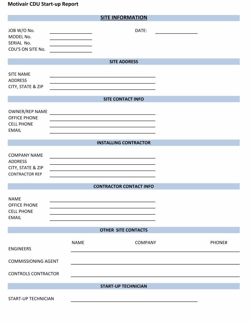
Motivair CDU Start‐up Report
DATE:
NAME
NAME COMPANY
SITE NAME
CONTRACTOR REP
CONTRACTOR CONTACT INFO
SERIAL No.
CDU'S ON SITE No.
SITE ADDRESS
SITE INFORMATION
JOB W/O No.
MODEL No.
OWNER/REP NAME
ADDRESS
CITY, STATE & ZIP
SITE CONTACT INFO
OFFICE PHONE
COMPANY NAME
ADDRESS
CITY, STATE & ZIP
OFFICE PHONE
CELL PHONE
INSTALLING CONTRACTOR
CELL PHONE
OTHER SITE CONTACTS
PHONE#
ENGINEERS
COMMISSIONING AGENT
CONTROLS CONTRACTOR
START‐UP TECHNICIAN
START‐UP TECHNICIAN
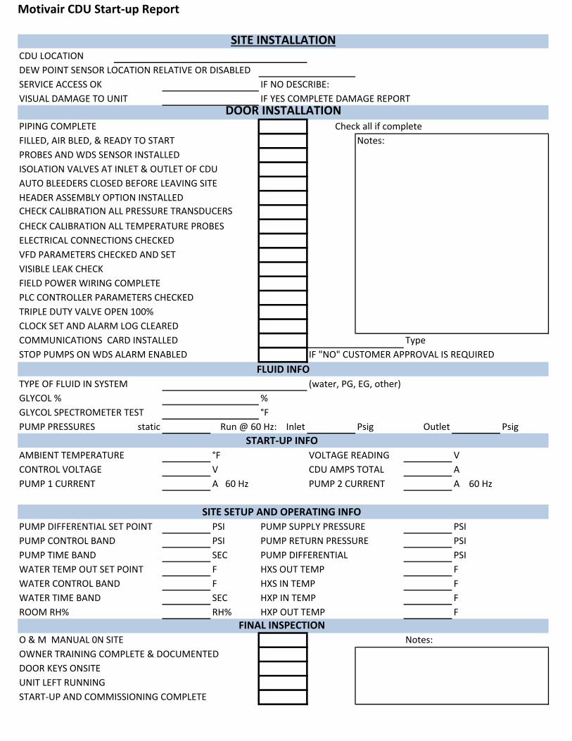
Motivair CDU Start‐up Report
CDU LOCATION
DEW POINT SENSOR LOCATION RELATIVE OR DISABLED
SERVICE ACCESS OK IF NO DESCRIBE:
PIPING COMPLETE Check all if complete
FILLED, AIR BLED, & READY TO START Notes:
PROBES AND WDS SENSOR INSTALLED
ISOLATION VALVES AT INLET & OUTLET OF CDU
AUTO BLEEDERS CLOSED BEFORE LEAVING SITE
HEADER ASSEMBLY OPTION INSTALLED
CHECK CALIBRATION ALL PRESSURE TRANSDUCERS
CHECK CALIBRATION ALL TEMPERATURE PROBES
ELECTRICAL CONNECTIONS CHECKED
VFD PARAMETERS CHECKED AND SET
VISIBLE LEAK CHECK
FIELD POWER WIRING COMPLETE
PLC CONTROLLER PARAMETERS CHECKED
Type
IF "NO" CUSTOMER APPROVAL IS REQUIRED
(water, PG, EG, other)
GLYCOL % %
GLYCOL SPECTROMETER TEST °F
static Psig Outlet Psig
AMBIENT TEMPERATURE °F VOLTAGE READING V
CONTROL VOLTAGE V CDU AMPS TOTAL A
PUMP 1 CURRENT A 60 Hz PUMP 2 CURRENT A 60 Hz
PUMP DIFFERENTIAL SET POINT PSI PUMP SUPPLY PRESSURE PSI
PSI PUMP RETURN PRESSURE PSI
SEC PUMP DIFFERENTIAL PSI
WATER TEMP OUT SET POINT F HXS OUT TEMP F
WATER CONTROL BAND F HXS IN TEMP F
SEC HXP IN TEMP F
RH% HXP OUT TEMP F
Notes:
OWNER TRAINING COMPLETE & DOCUMENTED
VISUAL DAMAGE TO UNIT IF YES COMPLETE DAMAGE REPORTDOOR INSTALLATION
SITE INSTALLATION
PUMP PRESSURES
TRIPLE DUTY VALVE OPEN 100%
CLOCK SET AND ALARM LOG CLEARED
Run @ 60 Hz: Inlet
STOP PUMPS ON WDS ALARM ENABLED
DOOR KEYS ONSITE
UNIT LEFT RUNNING
FINAL INSPECTION
O & M MANUAL 0N SITE
COMMUNICATIONS CARD INSTALLED
WATER TIME BAND
ROOM RH%
PUMP TIME BAND
PUMP CONTROL BAND
START‐UP INFO
SITE SETUP AND OPERATING INFO
FLUID INFO
TYPE OF FLUID IN SYSTEM
START‐UP AND COMMISSIONING COMPLETE
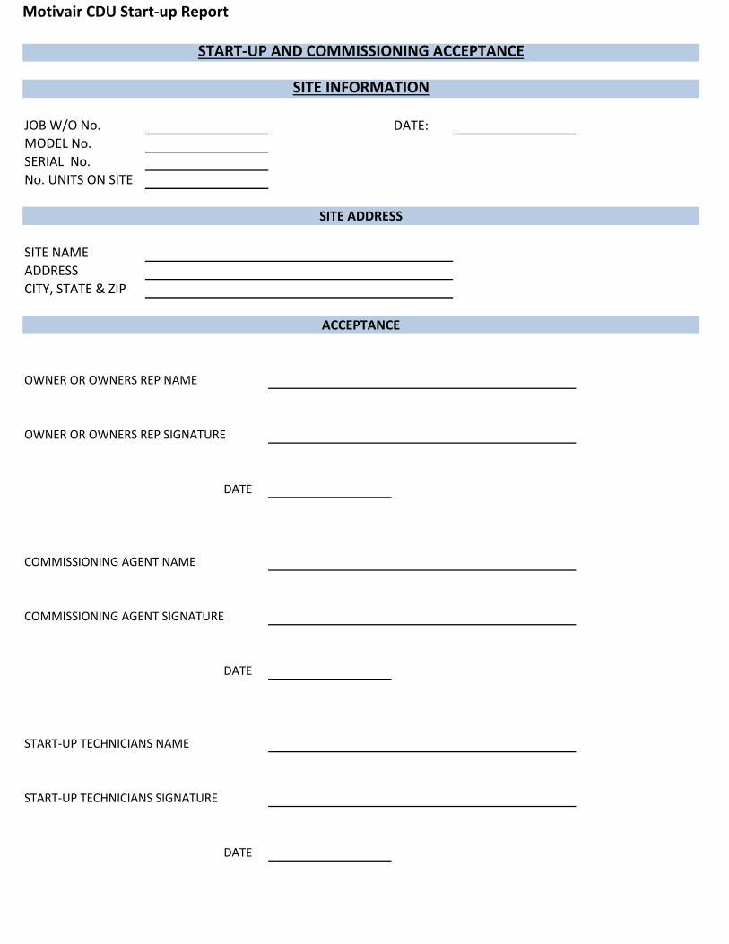
Motivair CDU Start‐up Report
DATE:
OWNER OR OWNERS REP NAME
OWNER OR OWNERS REP SIGNATURE
DATE
COMMISSIONING AGENT NAME
COMMISSIONING AGENT SIGNATURE
DATE
START‐UP TECHNICIANS NAME
START‐UP TECHNICIANS SIGNATURE
DATE
SITE ADDRESS
SITE NAME
START‐UP AND COMMISSIONING ACCEPTANCE
SITE INFORMATION
JOB W/O No.
MODEL No.
SERIAL No.
No. UNITS ON SITE
ADDRESS
CITY, STATE & ZIP
ACCEPTANCE